EP3637596A1 - Drive device-integrated rotary electric machine and electric power steering device using same - Google Patents
Drive device-integrated rotary electric machine and electric power steering device using same Download PDFInfo
- Publication number
- EP3637596A1 EP3637596A1 EP17912922.6A EP17912922A EP3637596A1 EP 3637596 A1 EP3637596 A1 EP 3637596A1 EP 17912922 A EP17912922 A EP 17912922A EP 3637596 A1 EP3637596 A1 EP 3637596A1
- Authority
- EP
- European Patent Office
- Prior art keywords
- power supply
- electric machine
- rotary electric
- drive device
- inverter unit
- Prior art date
- Legal status (The legal status is an assumption and is not a legal conclusion. Google has not performed a legal analysis and makes no representation as to the accuracy of the status listed.)
- Granted
Links
Images




Classifications
-
- H—ELECTRICITY
- H02—GENERATION; CONVERSION OR DISTRIBUTION OF ELECTRIC POWER
- H02P—CONTROL OR REGULATION OF ELECTRIC MOTORS, ELECTRIC GENERATORS OR DYNAMO-ELECTRIC CONVERTERS; CONTROLLING TRANSFORMERS, REACTORS OR CHOKE COILS
- H02P29/00—Arrangements for regulating or controlling electric motors, appropriate for both AC and DC motors
- H02P29/02—Providing protection against overload without automatic interruption of supply
- H02P29/024—Detecting a fault condition, e.g. short circuit, locked rotor, open circuit or loss of load
- H02P29/028—Detecting a fault condition, e.g. short circuit, locked rotor, open circuit or loss of load the motor continuing operation despite the fault condition, e.g. eliminating, compensating for or remedying the fault
-
- H—ELECTRICITY
- H02—GENERATION; CONVERSION OR DISTRIBUTION OF ELECTRIC POWER
- H02K—DYNAMO-ELECTRIC MACHINES
- H02K5/00—Casings; Enclosures; Supports
- H02K5/04—Casings or enclosures characterised by the shape, form or construction thereof
- H02K5/22—Auxiliary parts of casings not covered by groups H02K5/06-H02K5/20, e.g. shaped to form connection boxes or terminal boxes
- H02K5/225—Terminal boxes or connection arrangements
-
- B—PERFORMING OPERATIONS; TRANSPORTING
- B62—LAND VEHICLES FOR TRAVELLING OTHERWISE THAN ON RAILS
- B62D—MOTOR VEHICLES; TRAILERS
- B62D5/00—Power-assisted or power-driven steering
- B62D5/04—Power-assisted or power-driven steering electrical, e.g. using an electric servo-motor connected to, or forming part of, the steering gear
- B62D5/0403—Power-assisted or power-driven steering electrical, e.g. using an electric servo-motor connected to, or forming part of, the steering gear characterised by constructional features, e.g. common housing for motor and gear box
-
- B—PERFORMING OPERATIONS; TRANSPORTING
- B62—LAND VEHICLES FOR TRAVELLING OTHERWISE THAN ON RAILS
- B62D—MOTOR VEHICLES; TRAILERS
- B62D5/00—Power-assisted or power-driven steering
- B62D5/04—Power-assisted or power-driven steering electrical, e.g. using an electric servo-motor connected to, or forming part of, the steering gear
- B62D5/0421—Electric motor acting on or near steering gear
-
- H—ELECTRICITY
- H02—GENERATION; CONVERSION OR DISTRIBUTION OF ELECTRIC POWER
- H02K—DYNAMO-ELECTRIC MACHINES
- H02K11/00—Structural association of dynamo-electric machines with electric components or with devices for shielding, monitoring or protection
- H02K11/30—Structural association with control circuits or drive circuits
- H02K11/33—Drive circuits, e.g. power electronics
-
- H—ELECTRICITY
- H02—GENERATION; CONVERSION OR DISTRIBUTION OF ELECTRIC POWER
- H02P—CONTROL OR REGULATION OF ELECTRIC MOTORS, ELECTRIC GENERATORS OR DYNAMO-ELECTRIC CONVERTERS; CONTROLLING TRANSFORMERS, REACTORS OR CHOKE COILS
- H02P27/00—Arrangements or methods for the control of AC motors characterised by the kind of supply voltage
- H02P27/04—Arrangements or methods for the control of AC motors characterised by the kind of supply voltage using variable-frequency supply voltage, e.g. inverter or converter supply voltage
- H02P27/06—Arrangements or methods for the control of AC motors characterised by the kind of supply voltage using variable-frequency supply voltage, e.g. inverter or converter supply voltage using DC to AC converters or inverters
- H02P27/08—Arrangements or methods for the control of AC motors characterised by the kind of supply voltage using variable-frequency supply voltage, e.g. inverter or converter supply voltage using DC to AC converters or inverters with pulse width modulation
-
- B—PERFORMING OPERATIONS; TRANSPORTING
- B62—LAND VEHICLES FOR TRAVELLING OTHERWISE THAN ON RAILS
- B62D—MOTOR VEHICLES; TRAILERS
- B62D3/00—Steering gears
- B62D3/02—Steering gears mechanical
- B62D3/12—Steering gears mechanical of rack-and-pinion type
-
- B—PERFORMING OPERATIONS; TRANSPORTING
- B62—LAND VEHICLES FOR TRAVELLING OTHERWISE THAN ON RAILS
- B62D—MOTOR VEHICLES; TRAILERS
- B62D5/00—Power-assisted or power-driven steering
- B62D5/04—Power-assisted or power-driven steering electrical, e.g. using an electric servo-motor connected to, or forming part of, the steering gear
- B62D5/0421—Electric motor acting on or near steering gear
- B62D5/0424—Electric motor acting on or near steering gear the axes of motor and final driven element of steering gear, e.g. rack, being parallel
-
- H—ELECTRICITY
- H02—GENERATION; CONVERSION OR DISTRIBUTION OF ELECTRIC POWER
- H02P—CONTROL OR REGULATION OF ELECTRIC MOTORS, ELECTRIC GENERATORS OR DYNAMO-ELECTRIC CONVERTERS; CONTROLLING TRANSFORMERS, REACTORS OR CHOKE COILS
- H02P25/00—Arrangements or methods for the control of AC motors characterised by the kind of AC motor or by structural details
- H02P25/16—Arrangements or methods for the control of AC motors characterised by the kind of AC motor or by structural details characterised by the circuit arrangement or by the kind of wiring
- H02P25/22—Multiple windings; Windings for more than three phases
Definitions
- the present invention relates to a drive device-integrated rotary electric machine used as, for example, a vehicle-use rotary electric machine, and to an electric power steering device in which the drive device-integrated rotary electric machine is used.
- a double inverter type drive device-integrated rotary electric machine that has two sets of each of a power supply connector, an inverter, and a three-phase winding in order to enable restriction of a fluctuation in a power supply to another vehicle-mounted device while creating sufficient redundancy in a supply of power to an electric power steering device, and in which two sets of power supply connectors of the same current capacity are provided, has been disclosed to date in, for example, JP-A-2016-32977 (Patent Document 1) as this kind of drive device-integrated rotary electric machine.
- Patent Document 1 JP-A-2016-32977 ( Fig. 2 )
- the drive device-integrated rotary electric machine disclosed in Patent Document 1 is such that when there is an abnormality in one power supply line, a supply of power to a controller can be continued using another power supply line, because of which there is an advantage in that sufficient redundancy can be created in a supply of power to the electric power steering device.
- the size of the device increases in order to secure space in which to install the two sets of power supply connectors, and space for inserting and removing the connectors.
- the invention having been contrived in order to resolve such a problem, has an object of obtaining a drive device-integrated rotary electric machine, and an electric power steering device in which the drive device-integrated rotary electric machine is used, such that two sets of power supply connectors can be provided without increasing the size of the device.
- a drive device-integrated rotary electric machine is a drive device-integrated rotary electric machine including a rotary electric machine having a first three-phase winding and a second three-phase winding, a first inverter unit that supplies a drive current to the first three-phase winding, a second inverter unit that supplies a drive current to the second three-phase winding, a first power supply connector that connects the first inverter unit to a first vehicle power supply, and a second power supply connector that connects the second inverter unit to a second vehicle power supply, wherein a voltage of the first vehicle power supply is higher than a voltage of the second vehicle power supply, and a current capacity of the first power supply connector is smaller than a current capacity of the second power supply connector.
- two sets of power supply connectors can be provided without increasing the size of a device, because of which a drive device-integrated rotary electric machine with good ease of mounting and assembly workability can be obtained.
- Fig. 1 is a side view of a drive device-integrated rotary electric machine according to a first embodiment of the invention
- Fig. 2 shows an end view of a non-output shaft side of the drive device-integrated rotary electric machine
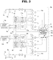
- Fig. 3 is a circuit block diagram of the drive device-integrated rotary electric machine.
- a rotary electric machine 1 is a permanent magnet synchronized motor, wherein two sets of three-phase windings are wound around an unshown stator, forming a three-phase duplex motor.
- a coupling mechanism 2, such as a coupling or a pulley, to be coupled to a vehicle steering mechanism is attached to an output shaft side end portion of the rotary electric machine 1.
- a drive device 3 is coaxially and integrally attached to an end portion of the rotary electric machine 1 on a side opposite to that of the coupling mechanism 2, configuring a drive device-integrated rotary electric machine 4a.
- a first power supply connector 5a, a second power supply connector 5b, a first signal connector 6a, and a second signal connector 6b are provided on an end portion of the drive device 3.
- the first power supply connector 5a is connected to a first vehicle power supply 7a, as shown in Fig. 3
- the second power supply connector 5b is connected to a second vehicle power supply 7b whose power supply voltage is lower than that of the first vehicle power supply 7a.
- the drive device 3 has two sets formed of a first power supply circuit 8a, a second power supply circuit 8b, a first input circuit 9a, a second input circuit 9b, a first CPU 10a, a second CPU 10b, a first FET drive circuit 11a, a second FET drive circuit 11b, a first inverter unit 12a configured of power elements such as power MOSFETs, wherein three phases' worth configure one set, and a second inverter unit 12b configured in the same way as the first inverter unit 12a.
- the first power supply circuit 8a, the second power supply circuit 8b, the first input circuit 9a, the second input circuit 9b, the first CPU 10a, the second CPU 10b, the first FET drive circuit 11a, and the second FET drive circuit 11b configure a control circuit of the drive device 3.
- a signal from a second steering sensor 13b configuring a steering mechanism, and a vehicle signal such as vehicle speed are input via the second signal connector 6b into the second input circuit 9b, and furthermore, a signal from a second rotation sensor 14b, which detects the angle of rotation of the unshown rotor of the rotary electric machine 1 using wiring in the device interior, is input.
- the first inverter unit 12a and the second inverter unit 12b are connected to the first vehicle power supply 7a and the second vehicle power supply 7b respectively via the first power supply connector 5a and the second power supply connector 5b.
- Three-phase outputs of the first inverter unit 12a and the second inverter unit 12b are connected by wiring in the device interior to a first three-phase winding 15a and a second three-phase winding 15b respectively of the rotary electric machine 1, thereby supplying a drive current.
- a current capacity of the first power supply connector 5a is smaller than a current capacity of the second power supply connector 5b.
- a current capacity being small means that a size of a connector terminal (mainly a terminal width) is small, that is, a current capacity being small means that an actual size of a power supply connector is small. Because of this, it is sufficient that a space in which the power supply connector is installed is small, whereby an increase in size of a device is prevented.
- a connector current capacity is a value of an allowed current with which a connector can be energized, and is set to be a value such that, for example, a value of a temperature rise of the connector when energizing continuously with a constant current comes within an allowed range, with consideration to a connector terminal material, a connector housing material, a usage environment, and the like.
- the current capacities of the two sets of power supply connectors are set so that products of a power supply voltage and the current capacities of the two sets are practically equal values. For example, when the power supply voltage of the first vehicle power supply 7a on a high voltage side is four times the power supply voltage of the second vehicle power supply 7b on a low voltage side, the current capacity of the first power supply connector 5a connected to the first vehicle power supply 7a is one-fourth of the current capacity of the second power supply connector 5b connected to the second vehicle power supply 7b.
- outputs of the rotary electric machine 1 generated by the two sets of three-phase windings that is, the first three-phase winding 15a and the second three-phase winding 15b, are designed so as to be equal, and means that powers, that is, products of voltage and current, that need to be supplied to the two sets of drive circuits, that is, the first FET drive circuit 11a and the second FET drive circuit 11b, are equal. Therefore, the current capacity of the first power supply connector 5a on the high voltage side can be reduced by an amount by which the voltage increases.
- a modulation rate of the first inverter unit 12a on the high voltage side is reduced with respect to a modulation rate of the second inverter unit 12b on the low voltage side by a power supply voltage ratio (the power supply voltage of the second vehicle power supply 7b / the power supply voltage of the first vehicle power supply 7a), an induced voltage constant of the first three-phase winding 15a on the high voltage side is increased with respect to an induced voltage constant of the second three-phase winding 15b on the low voltage side by a power supply voltage ratio (the power supply voltage of the first vehicle power supply 7a / the power supply voltage of the second vehicle power supply 7b), or the like.
- a reason two sets of power supply voltages with differing vehicle power supplies are prepared is, in addition to securing redundancy by duplicating the power supplies, to cause the configurations of the two power supplies to differ, thereby avoiding failures occurring simultaneously due to the same cause.
- vehicles in which a high voltage battery is mounted such as an electric vehicle, a plug-in hybrid vehicle, and a hybrid vehicle, have been increasing, and preparing a 12V power supply from an existing lead battery, and a power supply stepped down from the high voltage batteries, a 48V power supply for example, can be carried out comparatively easily.
- the drive device-integrated rotary electric machine 4a includes connectors, power supply circuits, input circuits, CPUs, FET drive circuits, inverter units, three-phase windings, and rotation sensors, and forms a complete dual system wherein all components controlling a drive of the rotary electric machine 1 are configured in duplicate, meaning that even when one system fails, the other system can continue to drive unaffected, whereby reliability increases considerably.
- FIG. 4 is a configuration drawing of an electric power steering device wherein the drive device-integrated rotary electric machine according to the first embodiment is mounted in a vehicle.
- a steering shaft 41 is coupled to a steering wheel 40 operated by a driver.
- the first steering sensor 13a and the second steering sensor 13b which detect a steering angle or a steering torque of the driver, are attached to the steering shaft 41.
- Tie rods 44a and 44b coupled to a rack shaft 43 are connected to knuckle arms 42a and 42b of front wheels 41a and 41b, which are steered wheels, and movement of the rack shaft 43 is transmitted to the front wheels 41a and 41b via the tie rods 44a and 44b and the knuckle arms 42a and 42b. Because of this, the front wheels 41a and 41b are steered.
- the drive device-integrated rotary electric machine 4a which is a steering motor, is attached to the rack shaft 43, and an output of the drive device-integrated rotary electric machine 4a forms power that causes the rack shaft 43 to move.
- An electric power steering device 45 wherein steering in accordance with an operation by a driver is performed is formed by the drive device 3 appropriately controlling the rotary electric machine 1 based on input signals from the first steering sensor 13a and the second steering sensor 13b, and on a vehicle signal such as vehicle speed.
- the first power supply connector 5a, the second power supply connector 5b, the first signal connector 6a, and the second signal connector 6b are led out to the non-output shaft side from an axial direction end face of the drive device 3, but a lead-out direction of the connectors not being limited to this, the connectors may be led out in a radial direction. Also, a radial direction protruding portion may be provided on the drive device 3, and each connector may be led out to an output shaft side from the radial direction protruding portion. Furthermore, not being limited to a configuration wherein each connector is led out in the same direction, the connectors may be led out in different directions as appropriate in accordance with a layout of a vehicle.
- the drive device-integrated rotary electric machine 4a configured in this way is such that the two sets of power supply voltages differ, and the size of the first power supply connector 5a on the high voltage side is reduced, because of which an external form of the device is small even though the connectors, the control circuits, the inverters, and the three-phase windings are duplicated, and ease of mounting in a vehicle, and ease of inserting and removing the connectors, are good. Also, manufacturing cost can be reduced.
- the drive device-integrated rotary electric machine 4a having these kinds of characteristic is such that high reliability and redundancy can be balanced with size reduction and weight reduction, because of which the drive device-integrated rotary electric machine 4a is particularly suitable as a device used in the vehicle electric power steering device 45.
- FIG. 5 is a circuit block diagram showing a drive device-integrated rotary electric machine 4b according to the second embodiment.
- a configuration has a power supply switching device 50, which is switching means that switches between the first vehicle power supply 7a input via the first power supply connector 5a and the second vehicle power supply 7b input via the second power supply connector 5b, and connects only either one thereof to the first power supply circuit 8a, the first inverter unit 12a, the second power supply circuit 8b, and the second inverter unit 12b.
- Other configurations are the same as in the first embodiment, and a redundant description is omitted by allotting the same reference signs.
- the drive device-integrated rotary electric machine 4b according to the second embodiment is such that even when one vehicle power supply fails, power can be supplied normally to the two sets of control circuits, inverters, and three-phase windings of the device, because of which the device can generate the same output as at a normal time.
- induced voltage constants of the first three-phase winding 15a and the second three-phase winding 15b are configured so as to be equal.
- the drive device-integrated rotary electric machine 4b configured in this way is such that, in the same way as the drive device-integrated rotary electric machine 4a according to the first embodiment, the two sets of power supply voltages differ, and the size of the first power supply connector 5a on the high voltage side is reduced, because of which the external form of the device is small even though the connectors, the control circuits, the inverters, and the three-phase windings are duplicated, and ease of mounting in a vehicle, and ease of inserting and removing the connectors, are good. Furthermore, even when one of the first vehicle power supply 7a and the second vehicle power supply 7b fails, the device can be caused to operate normally, with no decrease in performance, by the power supply switching device 50 being switched to the vehicle power supply on the normal side.
- the drive device-integrated rotary electric machine 4b having this kind of characteristic is such that high reliability and redundancy can be balanced with size reduction and weight reduction, because of which, in the same way as the drive device-integrated rotary electric machine 4a according to the first embodiment, the drive device-integrated rotary electric machine 4b is particularly suitable for use in the vehicle electric power steering.
Landscapes
- Engineering & Computer Science (AREA)
- Power Engineering (AREA)
- Chemical & Material Sciences (AREA)
- Combustion & Propulsion (AREA)
- Transportation (AREA)
- Mechanical Engineering (AREA)
- Microelectronics & Electronic Packaging (AREA)
- Power Steering Mechanism (AREA)
- Steering Control In Accordance With Driving Conditions (AREA)
- Control Of Ac Motors In General (AREA)
- Motor Or Generator Frames (AREA)
Abstract
Description
- The present invention relates to a drive device-integrated rotary electric machine used as, for example, a vehicle-use rotary electric machine, and to an electric power steering device in which the drive device-integrated rotary electric machine is used.
- A double inverter type drive device-integrated rotary electric machine that has two sets of each of a power supply connector, an inverter, and a three-phase winding in order to enable restriction of a fluctuation in a power supply to another vehicle-mounted device while creating sufficient redundancy in a supply of power to an electric power steering device, and in which two sets of power supply connectors of the same current capacity are provided, has been disclosed to date in, for example,
JP-A-2016-32977 - Patent Document 1:
JP-A-2016-32977 Fig. 2 ) - The drive device-integrated rotary electric machine disclosed in
Patent Document 1 is such that when there is an abnormality in one power supply line, a supply of power to a controller can be continued using another power supply line, because of which there is an advantage in that sufficient redundancy can be created in a supply of power to the electric power steering device. However, there is a problem with the drive device-integrated rotary electric machine in that the size of the device increases in order to secure space in which to install the two sets of power supply connectors, and space for inserting and removing the connectors. - The invention, having been contrived in order to resolve such a problem, has an object of obtaining a drive device-integrated rotary electric machine, and an electric power steering device in which the drive device-integrated rotary electric machine is used, such that two sets of power supply connectors can be provided without increasing the size of the device.
- A drive device-integrated rotary electric machine according to the invention is a drive device-integrated rotary electric machine including a rotary electric machine having a first three-phase winding and a second three-phase winding, a first inverter unit that supplies a drive current to the first three-phase winding, a second inverter unit that supplies a drive current to the second three-phase winding, a first power supply connector that connects the first inverter unit to a first vehicle power supply, and a second power supply connector that connects the second inverter unit to a second vehicle power supply, wherein a voltage of the first vehicle power supply is higher than a voltage of the second vehicle power supply, and a current capacity of the first power supply connector is smaller than a current capacity of the second power supply connector.
- According to the invention, two sets of power supply connectors can be provided without increasing the size of a device, because of which a drive device-integrated rotary electric machine with good ease of mounting and assembly workability can be obtained.
- Objects, characteristics, aspects, and advantages of the invention other than those heretofore described will become more apparent from the following detailed description of the invention, which refers to the drawings.
-
- [
Fig. 1] Fig. 1 is a side view of a drive device-integrated rotary electric machine according to a first embodiment of the invention. - [
Fig. 2] Fig. 2 is an end view of a non-output shaft side of the drive device-integrated rotary electric machine according to the first embodiment of the invention. - [
Fig. 3] Fig. 3 is a circuit block diagram of the drive device-integrated rotary electric machine according to the first embodiment of the invention. - [
Fig. 4] Fig. 4 is a configuration drawing of an electric power steering device wherein the drive device-integrated rotary electric machine according to the first embodiment of the invention is mounted in a vehicle. - [
Fig. 5] Fig. 5 is a circuit block diagram of a drive device-integrated rotary electric machine according to a second embodiment of the invention. - Hereafter, preferred embodiments of a drive device-integrated rotary electric machine according to the invention, and an electric power steering device in which the drive device-integrated rotary electric machine is used, will be described in detail, with reference to the drawings.
-
Fig. 1 is a side view of a drive device-integrated rotary electric machine according to a first embodiment of the invention,Fig. 2 shows an end view of a non-output shaft side of the drive device-integrated rotary electric machine, andFig. 3 is a circuit block diagram of the drive device-integrated rotary electric machine. - In
Fig. 1 to Fig. 3 , a rotaryelectric machine 1 is a permanent magnet synchronized motor, wherein two sets of three-phase windings are wound around an unshown stator, forming a three-phase duplex motor. Acoupling mechanism 2, such as a coupling or a pulley, to be coupled to a vehicle steering mechanism is attached to an output shaft side end portion of the rotaryelectric machine 1. Also, adrive device 3 is coaxially and integrally attached to an end portion of the rotaryelectric machine 1 on a side opposite to that of thecoupling mechanism 2, configuring a drive device-integrated rotaryelectric machine 4a. - A first
power supply connector 5a, a secondpower supply connector 5b, afirst signal connector 6a, and asecond signal connector 6b are provided on an end portion of thedrive device 3. The firstpower supply connector 5a is connected to a firstvehicle power supply 7a, as shown inFig. 3 , and the secondpower supply connector 5b is connected to a secondvehicle power supply 7b whose power supply voltage is lower than that of the firstvehicle power supply 7a. - The
drive device 3 has two sets formed of a firstpower supply circuit 8a, a secondpower supply circuit 8b, afirst input circuit 9a, asecond input circuit 9b, afirst CPU 10a, asecond CPU 10b, a firstFET drive circuit 11a, a secondFET drive circuit 11b, afirst inverter unit 12a configured of power elements such as power MOSFETs, wherein three phases' worth configure one set, and asecond inverter unit 12b configured in the same way as thefirst inverter unit 12a. The firstpower supply circuit 8a, the secondpower supply circuit 8b, thefirst input circuit 9a, thesecond input circuit 9b, thefirst CPU 10a, thesecond CPU 10b, the firstFET drive circuit 11a, and the secondFET drive circuit 11b configure a control circuit of thedrive device 3. - A signal from a
first steering sensor 13a configuring a steering mechanism, and a vehicle signal such as vehicle speed, are input via thefirst signal connector 6a into thefirst input circuit 9a, and furthermore, a signal from afirst rotation sensor 14a, which detects an angle of rotation of an unshown rotor of the rotaryelectric machine 1 using wiring in a device interior, is input. In the same way, a signal from asecond steering sensor 13b configuring a steering mechanism, and a vehicle signal such as vehicle speed, are input via thesecond signal connector 6b into thesecond input circuit 9b, and furthermore, a signal from asecond rotation sensor 14b, which detects the angle of rotation of the unshown rotor of the rotaryelectric machine 1 using wiring in the device interior, is input. Thefirst inverter unit 12a and thesecond inverter unit 12b are connected to the firstvehicle power supply 7a and the secondvehicle power supply 7b respectively via the firstpower supply connector 5a and the secondpower supply connector 5b. Three-phase outputs of thefirst inverter unit 12a and thesecond inverter unit 12b are connected by wiring in the device interior to a first three-phase winding 15a and a second three-phase winding 15b respectively of the rotaryelectric machine 1, thereby supplying a drive current. - A current capacity of the first
power supply connector 5a is smaller than a current capacity of the secondpower supply connector 5b. A current capacity being small means that a size of a connector terminal (mainly a terminal width) is small, that is, a current capacity being small means that an actual size of a power supply connector is small. Because of this, it is sufficient that a space in which the power supply connector is installed is small, whereby an increase in size of a device is prevented. It not being sufficient that a connector with the external dimensions thereof can be physically disposed, it is necessary to secure a space in which to insert and remove the connector in a state mounted in a vehicle, so when reducing the size of the connector, an advantage more than equivalent to an amount by which the size of the connector itself is reduced is obtained in reducing the size of the device. Herein, a connector current capacity is a value of an allowed current with which a connector can be energized, and is set to be a value such that, for example, a value of a temperature rise of the connector when energizing continuously with a constant current comes within an allowed range, with consideration to a connector terminal material, a connector housing material, a usage environment, and the like. - The current capacities of the two sets of power supply connectors, those being the first
power supply connector 5a and the secondpower supply connector 5b, are set so that products of a power supply voltage and the current capacities of the two sets are practically equal values. For example, when the power supply voltage of the firstvehicle power supply 7a on a high voltage side is four times the power supply voltage of the secondvehicle power supply 7b on a low voltage side, the current capacity of the firstpower supply connector 5a connected to the firstvehicle power supply 7a is one-fourth of the current capacity of the secondpower supply connector 5b connected to the secondvehicle power supply 7b. This is because outputs of the rotaryelectric machine 1 generated by the two sets of three-phase windings, that is, the first three-phase winding 15a and the second three-phase winding 15b, are designed so as to be equal, and means that powers, that is, products of voltage and current, that need to be supplied to the two sets of drive circuits, that is, the firstFET drive circuit 11a and the secondFET drive circuit 11b, are equal. Therefore, the current capacity of the firstpower supply connector 5a on the high voltage side can be reduced by an amount by which the voltage increases. - As a method of arranging so that the outputs of the rotary
electric machine 1 generated by the two sets of three-phase windings, those being the first three-phase winding 15a and the second three-phase winding 15b, are equal, a modulation rate of thefirst inverter unit 12a on the high voltage side is reduced with respect to a modulation rate of thesecond inverter unit 12b on the low voltage side by a power supply voltage ratio (the power supply voltage of the secondvehicle power supply 7b / the power supply voltage of the firstvehicle power supply 7a), an induced voltage constant of the first three-phase winding 15a on the high voltage side is increased with respect to an induced voltage constant of the second three-phase winding 15b on the low voltage side by a power supply voltage ratio (the power supply voltage of the firstvehicle power supply 7a / the power supply voltage of the secondvehicle power supply 7b), or the like. - A reason two sets of power supply voltages with differing vehicle power supplies are prepared is, in addition to securing redundancy by duplicating the power supplies, to cause the configurations of the two power supplies to differ, thereby avoiding failures occurring simultaneously due to the same cause. In recent years, vehicles in which a high voltage battery is mounted, such as an electric vehicle, a plug-in hybrid vehicle, and a hybrid vehicle, have been increasing, and preparing a 12V power supply from an existing lead battery, and a power supply stepped down from the high voltage batteries, a 48V power supply for example, can be carried out comparatively easily.
- As heretofore described, the drive device-integrated rotary
electric machine 4a includes connectors, power supply circuits, input circuits, CPUs, FET drive circuits, inverter units, three-phase windings, and rotation sensors, and forms a complete dual system wherein all components controlling a drive of the rotaryelectric machine 1 are configured in duplicate, meaning that even when one system fails, the other system can continue to drive unaffected, whereby reliability increases considerably. - Next, a description will be given of an electric power steering device of a vehicle in which the drive device-integrated rotary
electric machine 4a according to the embodiment is mounted.Fig. 4 is a configuration drawing of an electric power steering device wherein the drive device-integrated rotary electric machine according to the first embodiment is mounted in a vehicle. - In
Fig. 4 , asteering shaft 41 is coupled to asteering wheel 40 operated by a driver. Thefirst steering sensor 13a and thesecond steering sensor 13b, which detect a steering angle or a steering torque of the driver, are attached to thesteering shaft 41.Tie rods rack shaft 43 are connected toknuckle arms front wheels rack shaft 43 is transmitted to thefront wheels tie rods knuckle arms front wheels electric machine 4a, which is a steering motor, is attached to therack shaft 43, and an output of the drive device-integrated rotaryelectric machine 4a forms power that causes therack shaft 43 to move. An electricpower steering device 45 wherein steering in accordance with an operation by a driver is performed is formed by thedrive device 3 appropriately controlling the rotaryelectric machine 1 based on input signals from thefirst steering sensor 13a and thesecond steering sensor 13b, and on a vehicle signal such as vehicle speed. - In the embodiment, the first
power supply connector 5a, the secondpower supply connector 5b, thefirst signal connector 6a, and thesecond signal connector 6b are led out to the non-output shaft side from an axial direction end face of thedrive device 3, but a lead-out direction of the connectors not being limited to this, the connectors may be led out in a radial direction. Also, a radial direction protruding portion may be provided on thedrive device 3, and each connector may be led out to an output shaft side from the radial direction protruding portion. Furthermore, not being limited to a configuration wherein each connector is led out in the same direction, the connectors may be led out in different directions as appropriate in accordance with a layout of a vehicle. - The drive device-integrated rotary
electric machine 4a configured in this way is such that the two sets of power supply voltages differ, and the size of the firstpower supply connector 5a on the high voltage side is reduced, because of which an external form of the device is small even though the connectors, the control circuits, the inverters, and the three-phase windings are duplicated, and ease of mounting in a vehicle, and ease of inserting and removing the connectors, are good. Also, manufacturing cost can be reduced. The drive device-integrated rotaryelectric machine 4a having these kinds of characteristic is such that high reliability and redundancy can be balanced with size reduction and weight reduction, because of which the drive device-integrated rotaryelectric machine 4a is particularly suitable as a device used in the vehicle electricpower steering device 45. - Next, a drive device-integrated rotary electric machine according to a second embodiment of the invention will be described.
Fig. 5 is a circuit block diagram showing a drive device-integrated rotaryelectric machine 4b according to the second embodiment. In the second embodiment, a configuration has a powersupply switching device 50, which is switching means that switches between the firstvehicle power supply 7a input via the firstpower supply connector 5a and the secondvehicle power supply 7b input via the secondpower supply connector 5b, and connects only either one thereof to the firstpower supply circuit 8a, thefirst inverter unit 12a, the secondpower supply circuit 8b, and thesecond inverter unit 12b. Other configurations are the same as in the first embodiment, and a redundant description is omitted by allotting the same reference signs. - The drive device-integrated rotary
electric machine 4b according to the second embodiment is such that even when one vehicle power supply fails, power can be supplied normally to the two sets of control circuits, inverters, and three-phase windings of the device, because of which the device can generate the same output as at a normal time. In the embodiment, induced voltage constants of the first three-phase winding 15a and the second three-phase winding 15b are configured so as to be equal. - The drive device-integrated rotary
electric machine 4b configured in this way is such that, in the same way as the drive device-integrated rotaryelectric machine 4a according to the first embodiment, the two sets of power supply voltages differ, and the size of the firstpower supply connector 5a on the high voltage side is reduced, because of which the external form of the device is small even though the connectors, the control circuits, the inverters, and the three-phase windings are duplicated, and ease of mounting in a vehicle, and ease of inserting and removing the connectors, are good. Furthermore, even when one of the firstvehicle power supply 7a and the secondvehicle power supply 7b fails, the device can be caused to operate normally, with no decrease in performance, by the powersupply switching device 50 being switched to the vehicle power supply on the normal side. The drive device-integrated rotaryelectric machine 4b having this kind of characteristic is such that high reliability and redundancy can be balanced with size reduction and weight reduction, because of which, in the same way as the drive device-integrated rotaryelectric machine 4a according to the first embodiment, the drive device-integrated rotaryelectric machine 4b is particularly suitable for use in the vehicle electric power steering. - The embodiments can be freely combined, and each embodiment can be modified or abbreviated as appropriate, without departing from the scope of the invention. Reference Signs List
- 1 rotary electric machine, 2 coupling mechanism, 3 drive device, 4a, 4b drive device-integrated rotary electric machine, 5a first power supply connector, 5b second power supply connector, 6a first signal connector, 6b second signal connector, 7a first vehicle power supply, 7b second vehicle power supply, 8a first power supply circuit, 8b second power supply circuit, 9a first input circuit, 9b second input circuit, 10a first CPU, 10b second CPU, 11a first FET drive circuit, 11b second FET drive circuit, 12a first inverter unit, 12b second inverter unit, 13a first steering sensor, 13b second steering sensor, 14a first rotation sensor, 14b second rotation sensor, 15a first three-phase winding, 15b second three-phase winding, 40 steering wheel, 41 steering shaft, 41a, 41b front wheel, 42a, 42b knuckle arm, 43 rack shaft, 44a, 44b tie rod, 45 electric power steering device, 50 power supply switching device.
Claims (7)
- A drive device-integrated rotary electric machine, comprising:a rotary electric machine having a first three-phase winding and a second three-phase winding;a first inverter unit that supplies a drive current to the first three-phase winding;a second inverter unit that supplies a drive current to the second three-phase winding;a first power supply connector that connects the first inverter unit to a first vehicle power supply; anda second power supply connector that connects the second inverter unit to a second vehicle power supply, whereina voltage of the first vehicle power supply is higher than a voltage of the second vehicle power supply, and a current capacity of the first power supply connector is smaller than a current capacity of the second power supply connector.
- The drive device-integrated rotary electric machine according to claim 1, wherein a product of the voltage of the first vehicle power supply and the current capacity of a first power supply connector and a product of the voltage of the second vehicle power supply and the current capacity of a second power supply connector are equal.
- The drive device-integrated rotary electric machine according to claim 1, wherein a modulation rate of the first inverter unit is smaller than a modulation rate of the second inverter unit.
- The drive device-integrated rotary electric machine according to claim 1, wherein an induced voltage constant of the first three-phase winding is greater than an induced voltage constant of the second three-phase winding.
- The drive device-integrated rotary electric machine according to any one of claims 1 to 4, wherein the first power supply connector and the second power supply connector are each provided independently from the first inverter unit or the second inverter unit.
- The drive device-integrated rotary electric machine according to claim 1 or 2, wherein the first power supply connector and the second power supply connector are provided in common to the first inverter unit and the second inverter unit, the rotary electric machine comprising switching means that can select either one of the first power supply connector and the second power supply connector, and connect the selected connector to the first inverter unit or the second inverter unit.
- An electric power steering device, comprising:a steering shaft coupled to a steering wheel operated by a driver;a first steering sensor and a second steering sensor, attached to the steering shaft, that detect a steering angle or a steering torque of the driver;a rack shaft coupled to the steering shaft; anda drive device-integrated rotary electric machine attached to the rack shaft, whereinthe drive device-integrated rotary electric machine is the drive device-integrated rotary electric machine according to any one of claims 1 to 6.
Applications Claiming Priority (1)
| Application Number | Priority Date | Filing Date | Title |
|---|---|---|---|
| PCT/JP2017/020798 WO2018225123A1 (en) | 2017-06-05 | 2017-06-05 | Drive device-integrated rotary electric machine and electric power steering device using same |
Publications (3)
| Publication Number | Publication Date |
|---|---|
| EP3637596A1 true EP3637596A1 (en) | 2020-04-15 |
| EP3637596A4 EP3637596A4 (en) | 2020-04-29 |
| EP3637596B1 EP3637596B1 (en) | 2021-11-17 |
Family
ID=64566062
Family Applications (1)
| Application Number | Title | Priority Date | Filing Date |
|---|---|---|---|
| EP17912922.6A Active EP3637596B1 (en) | 2017-06-05 | 2017-06-05 | Drive device-integrated rotary electric machine and electric power steering device using same |
Country Status (5)
| Country | Link |
|---|---|
| US (1) | US11533015B2 (en) |
| EP (1) | EP3637596B1 (en) |
| JP (1) | JP6721267B2 (en) |
| CN (1) | CN110679067B (en) |
| WO (1) | WO2018225123A1 (en) |
Cited By (1)
| Publication number | Priority date | Publication date | Assignee | Title |
|---|---|---|---|---|
| EP4237271A1 (en) * | 2020-12-22 | 2023-09-06 | Siemens Aktiengesellschaft | Connection connector for drive units |
Families Citing this family (6)
| Publication number | Priority date | Publication date | Assignee | Title |
|---|---|---|---|---|
| JP6907991B2 (en) * | 2018-04-10 | 2021-07-21 | 株式会社デンソー | Drive device |
| JP7472745B2 (en) * | 2020-09-30 | 2024-04-23 | 株式会社デンソー | Motor Drive System |
| JP7405055B2 (en) * | 2020-10-06 | 2023-12-26 | 株式会社デンソー | Rotating electric machine drive device |
| WO2022097325A1 (en) * | 2020-11-06 | 2022-05-12 | 日立Astemo株式会社 | Electric motor drive control device |
| DE102022111881A1 (en) * | 2022-05-12 | 2023-11-16 | Dr. Ing. H.C. F. Porsche Aktiengesellschaft | Method for operating an electric drive system with multiple energy storage devices |
| TWI814509B (en) * | 2022-08-01 | 2023-09-01 | 城市學校財團法人臺北城市科技大學 | Permanent magnet synchronous motor system with multistage driving capability via distributed electric batteries |
Family Cites Families (15)
| Publication number | Priority date | Publication date | Assignee | Title |
|---|---|---|---|---|
| JPH08168292A (en) * | 1994-12-15 | 1996-06-25 | Hitachi Ltd | Induction motor and electric vehicle using the same |
| JP2000264048A (en) * | 1999-03-16 | 2000-09-26 | Matsushita Electric Ind Co Ltd | Air conditioner |
| US7956563B2 (en) * | 2007-07-30 | 2011-06-07 | GM Global Technology Operations LLC | System for using a multi-phase motor with a double-ended inverter system |
| US20090033253A1 (en) * | 2007-07-30 | 2009-02-05 | Gm Global Technology Operations, Inc. | Electric traction system for a vehicle having a dual winding ac traction motor |
| CN102414043B (en) * | 2009-04-23 | 2014-03-19 | 丰田自动车株式会社 | Power supply system of electric vehicle and control method thereof |
| JP5995877B2 (en) * | 2012-01-11 | 2016-09-21 | 三菱電機株式会社 | Electric power steering device |
| JP5594312B2 (en) * | 2012-04-02 | 2014-09-24 | 株式会社デンソー | Motor drive device |
| US8928264B2 (en) * | 2012-04-05 | 2015-01-06 | Denso Corporation | Control device for rotating electrical machine |
| JP5784553B2 (en) * | 2012-07-10 | 2015-09-24 | 株式会社日本自動車部品総合研究所 | Power converter |
| JP5614661B2 (en) | 2012-10-09 | 2014-10-29 | 株式会社デンソー | Rotating electrical machine control device and electric power steering device using the same |
| JP5725055B2 (en) * | 2013-02-12 | 2015-05-27 | 株式会社デンソー | Electronic control unit |
| JP5846151B2 (en) * | 2013-04-05 | 2016-01-20 | 株式会社日本自動車部品総合研究所 | Power converter |
| US9634589B2 (en) * | 2013-07-23 | 2017-04-25 | Aisin Aw Co., Ltd. | Drive device |
| CN103684196B (en) * | 2013-11-19 | 2016-02-17 | 南京航空航天大学 | A kind of PMSM Drive System of changeable winding |
| JP2016032977A (en) | 2014-07-31 | 2016-03-10 | 株式会社デンソー | Electric power steering system and vehicle control system |
-
2017
- 2017-06-05 WO PCT/JP2017/020798 patent/WO2018225123A1/en not_active Ceased
- 2017-06-05 JP JP2019523218A patent/JP6721267B2/en active Active
- 2017-06-05 US US16/496,722 patent/US11533015B2/en active Active
- 2017-06-05 CN CN201780091119.6A patent/CN110679067B/en active Active
- 2017-06-05 EP EP17912922.6A patent/EP3637596B1/en active Active
Cited By (3)
| Publication number | Priority date | Publication date | Assignee | Title |
|---|---|---|---|---|
| EP4237271A1 (en) * | 2020-12-22 | 2023-09-06 | Siemens Aktiengesellschaft | Connection connector for drive units |
| EP4237271B1 (en) * | 2020-12-22 | 2026-03-11 | Siemens Aktiengesellschaft | Connector for drive units |
| US12594837B2 (en) | 2020-12-22 | 2026-04-07 | Siemens Aktiengesellschaft | Connection connector for drive units |
Also Published As
| Publication number | Publication date |
|---|---|
| JP6721267B2 (en) | 2020-07-08 |
| WO2018225123A1 (en) | 2018-12-13 |
| JPWO2018225123A1 (en) | 2019-11-21 |
| EP3637596A4 (en) | 2020-04-29 |
| US11533015B2 (en) | 2022-12-20 |
| EP3637596B1 (en) | 2021-11-17 |
| CN110679067A (en) | 2020-01-10 |
| CN110679067B (en) | 2021-07-02 |
| US20210111659A1 (en) | 2021-04-15 |
Similar Documents
| Publication | Publication Date | Title |
|---|---|---|
| US11533015B2 (en) | Drive device-integrated rotary electric machine and electric power steering device using same | |
| EP3403904B1 (en) | Electrical power steering device | |
| US12155276B2 (en) | Electric power steering apparatus | |
| JP7205352B2 (en) | Rotating electric machine control device and electric power steering device using the same | |
| US11870378B2 (en) | Rotary electric machine control apparatus | |
| CN104015787B (en) | Vehicle electric electronic-controlled power steering control system | |
| US11370373B2 (en) | Power source system | |
| US20140358375A1 (en) | Actuator control apparatus | |
| JP2016032977A (en) | Electric power steering system and vehicle control system | |
| US11760284B2 (en) | Electronic control unit and power supply system | |
| EP3624326B1 (en) | Electric power steering device | |
| US20210001919A1 (en) | Detection device, calculation device, control device, and electric power steering device using the same | |
| CN107251411A (en) | Electric driving device and control method thereof | |
| CN112236935B (en) | Electric power steering | |
| JP6439631B2 (en) | Electric power steering device | |
| JP2017047778A (en) | Electric power steering apparatus | |
| JP2025150895A (en) | Drive system | |
| CN112805915A (en) | Motor control system, motor, and electric power steering device |
Legal Events
| Date | Code | Title | Description |
|---|---|---|---|
| STAA | Information on the status of an ep patent application or granted ep patent |
Free format text: STATUS: THE INTERNATIONAL PUBLICATION HAS BEEN MADE |
|
| PUAI | Public reference made under article 153(3) epc to a published international application that has entered the european phase |
Free format text: ORIGINAL CODE: 0009012 |
|
| STAA | Information on the status of an ep patent application or granted ep patent |
Free format text: STATUS: REQUEST FOR EXAMINATION WAS MADE |
|
| 17P | Request for examination filed |
Effective date: 20190902 |
|
| AK | Designated contracting states |
Kind code of ref document: A1 Designated state(s): AL AT BE BG CH CY CZ DE DK EE ES FI FR GB GR HR HU IE IS IT LI LT LU LV MC MK MT NL NO PL PT RO RS SE SI SK SM TR |
|
| AX | Request for extension of the european patent |
Extension state: BA ME |
|
| A4 | Supplementary search report drawn up and despatched |
Effective date: 20200330 |
|
| RIC1 | Information provided on ipc code assigned before grant |
Ipc: H02K 11/33 20160101ALI20200324BHEP Ipc: B62D 5/04 20060101ALI20200324BHEP Ipc: H02K 5/22 20060101AFI20200324BHEP Ipc: H02P 25/22 20060101ALI20200324BHEP |
|
| DAV | Request for validation of the european patent (deleted) | ||
| DAX | Request for extension of the european patent (deleted) | ||
| RIC1 | Information provided on ipc code assigned before grant |
Ipc: H02K 5/22 20060101AFI20210722BHEP Ipc: B62D 5/04 20060101ALI20210722BHEP Ipc: H02K 11/33 20160101ALI20210722BHEP Ipc: H02P 25/22 20060101ALI20210722BHEP |
|
| GRAP | Despatch of communication of intention to grant a patent |
Free format text: ORIGINAL CODE: EPIDOSNIGR1 |
|
| STAA | Information on the status of an ep patent application or granted ep patent |
Free format text: STATUS: GRANT OF PATENT IS INTENDED |
|
| INTG | Intention to grant announced |
Effective date: 20210907 |
|
| GRAS | Grant fee paid |
Free format text: ORIGINAL CODE: EPIDOSNIGR3 |
|
| GRAA | (expected) grant |
Free format text: ORIGINAL CODE: 0009210 |
|
| STAA | Information on the status of an ep patent application or granted ep patent |
Free format text: STATUS: THE PATENT HAS BEEN GRANTED |
|
| AK | Designated contracting states |
Kind code of ref document: B1 Designated state(s): AL AT BE BG CH CY CZ DE DK EE ES FI FR GB GR HR HU IE IS IT LI LT LU LV MC MK MT NL NO PL PT RO RS SE SI SK SM TR |
|
| REG | Reference to a national code |
Ref country code: GB Ref legal event code: FG4D |
|
| REG | Reference to a national code |
Ref country code: IE Ref legal event code: FG4D |
|
| REG | Reference to a national code |
Ref country code: DE Ref legal event code: R096 Ref document number: 602017049651 Country of ref document: DE |
|
| REG | Reference to a national code |
Ref country code: AT Ref legal event code: REF Ref document number: 1448859 Country of ref document: AT Kind code of ref document: T Effective date: 20211215 |
|
| REG | Reference to a national code |
Ref country code: LT Ref legal event code: MG9D |
|
| REG | Reference to a national code |
Ref country code: NL Ref legal event code: MP Effective date: 20211117 |
|
| REG | Reference to a national code |
Ref country code: AT Ref legal event code: MK05 Ref document number: 1448859 Country of ref document: AT Kind code of ref document: T Effective date: 20211117 |
|
| PG25 | Lapsed in a contracting state [announced via postgrant information from national office to epo] |
Ref country code: RS Free format text: LAPSE BECAUSE OF FAILURE TO SUBMIT A TRANSLATION OF THE DESCRIPTION OR TO PAY THE FEE WITHIN THE PRESCRIBED TIME-LIMIT Effective date: 20211117 Ref country code: LT Free format text: LAPSE BECAUSE OF FAILURE TO SUBMIT A TRANSLATION OF THE DESCRIPTION OR TO PAY THE FEE WITHIN THE PRESCRIBED TIME-LIMIT Effective date: 20211117 Ref country code: FI Free format text: LAPSE BECAUSE OF FAILURE TO SUBMIT A TRANSLATION OF THE DESCRIPTION OR TO PAY THE FEE WITHIN THE PRESCRIBED TIME-LIMIT Effective date: 20211117 Ref country code: BG Free format text: LAPSE BECAUSE OF FAILURE TO SUBMIT A TRANSLATION OF THE DESCRIPTION OR TO PAY THE FEE WITHIN THE PRESCRIBED TIME-LIMIT Effective date: 20220217 Ref country code: AT Free format text: LAPSE BECAUSE OF FAILURE TO SUBMIT A TRANSLATION OF THE DESCRIPTION OR TO PAY THE FEE WITHIN THE PRESCRIBED TIME-LIMIT Effective date: 20211117 |
|
| PG25 | Lapsed in a contracting state [announced via postgrant information from national office to epo] |
Ref country code: IS Free format text: LAPSE BECAUSE OF FAILURE TO SUBMIT A TRANSLATION OF THE DESCRIPTION OR TO PAY THE FEE WITHIN THE PRESCRIBED TIME-LIMIT Effective date: 20220317 Ref country code: SE Free format text: LAPSE BECAUSE OF FAILURE TO SUBMIT A TRANSLATION OF THE DESCRIPTION OR TO PAY THE FEE WITHIN THE PRESCRIBED TIME-LIMIT Effective date: 20211117 Ref country code: PT Free format text: LAPSE BECAUSE OF FAILURE TO SUBMIT A TRANSLATION OF THE DESCRIPTION OR TO PAY THE FEE WITHIN THE PRESCRIBED TIME-LIMIT Effective date: 20220317 Ref country code: PL Free format text: LAPSE BECAUSE OF FAILURE TO SUBMIT A TRANSLATION OF THE DESCRIPTION OR TO PAY THE FEE WITHIN THE PRESCRIBED TIME-LIMIT Effective date: 20211117 Ref country code: NO Free format text: LAPSE BECAUSE OF FAILURE TO SUBMIT A TRANSLATION OF THE DESCRIPTION OR TO PAY THE FEE WITHIN THE PRESCRIBED TIME-LIMIT Effective date: 20220217 Ref country code: NL Free format text: LAPSE BECAUSE OF FAILURE TO SUBMIT A TRANSLATION OF THE DESCRIPTION OR TO PAY THE FEE WITHIN THE PRESCRIBED TIME-LIMIT Effective date: 20211117 Ref country code: LV Free format text: LAPSE BECAUSE OF FAILURE TO SUBMIT A TRANSLATION OF THE DESCRIPTION OR TO PAY THE FEE WITHIN THE PRESCRIBED TIME-LIMIT Effective date: 20211117 Ref country code: HR Free format text: LAPSE BECAUSE OF FAILURE TO SUBMIT A TRANSLATION OF THE DESCRIPTION OR TO PAY THE FEE WITHIN THE PRESCRIBED TIME-LIMIT Effective date: 20211117 Ref country code: GR Free format text: LAPSE BECAUSE OF FAILURE TO SUBMIT A TRANSLATION OF THE DESCRIPTION OR TO PAY THE FEE WITHIN THE PRESCRIBED TIME-LIMIT Effective date: 20220218 Ref country code: ES Free format text: LAPSE BECAUSE OF FAILURE TO SUBMIT A TRANSLATION OF THE DESCRIPTION OR TO PAY THE FEE WITHIN THE PRESCRIBED TIME-LIMIT Effective date: 20211117 |
|
| PG25 | Lapsed in a contracting state [announced via postgrant information from national office to epo] |
Ref country code: SM Free format text: LAPSE BECAUSE OF FAILURE TO SUBMIT A TRANSLATION OF THE DESCRIPTION OR TO PAY THE FEE WITHIN THE PRESCRIBED TIME-LIMIT Effective date: 20211117 Ref country code: SK Free format text: LAPSE BECAUSE OF FAILURE TO SUBMIT A TRANSLATION OF THE DESCRIPTION OR TO PAY THE FEE WITHIN THE PRESCRIBED TIME-LIMIT Effective date: 20211117 Ref country code: RO Free format text: LAPSE BECAUSE OF FAILURE TO SUBMIT A TRANSLATION OF THE DESCRIPTION OR TO PAY THE FEE WITHIN THE PRESCRIBED TIME-LIMIT Effective date: 20211117 Ref country code: EE Free format text: LAPSE BECAUSE OF FAILURE TO SUBMIT A TRANSLATION OF THE DESCRIPTION OR TO PAY THE FEE WITHIN THE PRESCRIBED TIME-LIMIT Effective date: 20211117 Ref country code: DK Free format text: LAPSE BECAUSE OF FAILURE TO SUBMIT A TRANSLATION OF THE DESCRIPTION OR TO PAY THE FEE WITHIN THE PRESCRIBED TIME-LIMIT Effective date: 20211117 Ref country code: CZ Free format text: LAPSE BECAUSE OF FAILURE TO SUBMIT A TRANSLATION OF THE DESCRIPTION OR TO PAY THE FEE WITHIN THE PRESCRIBED TIME-LIMIT Effective date: 20211117 |
|
| REG | Reference to a national code |
Ref country code: DE Ref legal event code: R097 Ref document number: 602017049651 Country of ref document: DE |
|
| PLBE | No opposition filed within time limit |
Free format text: ORIGINAL CODE: 0009261 |
|
| STAA | Information on the status of an ep patent application or granted ep patent |
Free format text: STATUS: NO OPPOSITION FILED WITHIN TIME LIMIT |
|
| 26N | No opposition filed |
Effective date: 20220818 |
|
| PG25 | Lapsed in a contracting state [announced via postgrant information from national office to epo] |
Ref country code: AL Free format text: LAPSE BECAUSE OF FAILURE TO SUBMIT A TRANSLATION OF THE DESCRIPTION OR TO PAY THE FEE WITHIN THE PRESCRIBED TIME-LIMIT Effective date: 20211117 |
|
| PG25 | Lapsed in a contracting state [announced via postgrant information from national office to epo] |
Ref country code: SI Free format text: LAPSE BECAUSE OF FAILURE TO SUBMIT A TRANSLATION OF THE DESCRIPTION OR TO PAY THE FEE WITHIN THE PRESCRIBED TIME-LIMIT Effective date: 20211117 |
|
| PG25 | Lapsed in a contracting state [announced via postgrant information from national office to epo] |
Ref country code: MC Free format text: LAPSE BECAUSE OF FAILURE TO SUBMIT A TRANSLATION OF THE DESCRIPTION OR TO PAY THE FEE WITHIN THE PRESCRIBED TIME-LIMIT Effective date: 20211117 |
|
| REG | Reference to a national code |
Ref country code: CH Ref legal event code: PL |
|
| REG | Reference to a national code |
Ref country code: BE Ref legal event code: MM Effective date: 20220630 |
|
| GBPC | Gb: european patent ceased through non-payment of renewal fee |
Effective date: 20220605 |
|
| PG25 | Lapsed in a contracting state [announced via postgrant information from national office to epo] |
Ref country code: LU Free format text: LAPSE BECAUSE OF NON-PAYMENT OF DUE FEES Effective date: 20220605 Ref country code: LI Free format text: LAPSE BECAUSE OF NON-PAYMENT OF DUE FEES Effective date: 20220630 Ref country code: IE Free format text: LAPSE BECAUSE OF NON-PAYMENT OF DUE FEES Effective date: 20220605 Ref country code: CH Free format text: LAPSE BECAUSE OF NON-PAYMENT OF DUE FEES Effective date: 20220630 |
|
| PG25 | Lapsed in a contracting state [announced via postgrant information from national office to epo] |
Ref country code: IT Free format text: LAPSE BECAUSE OF FAILURE TO SUBMIT A TRANSLATION OF THE DESCRIPTION OR TO PAY THE FEE WITHIN THE PRESCRIBED TIME-LIMIT Effective date: 20211117 Ref country code: GB Free format text: LAPSE BECAUSE OF NON-PAYMENT OF DUE FEES Effective date: 20220605 Ref country code: BE Free format text: LAPSE BECAUSE OF NON-PAYMENT OF DUE FEES Effective date: 20220630 |
|
| P01 | Opt-out of the competence of the unified patent court (upc) registered |
Effective date: 20230512 |
|
| REG | Reference to a national code |
Ref country code: DE Ref legal event code: R084 Ref document number: 602017049651 Country of ref document: DE |
|
| PG25 | Lapsed in a contracting state [announced via postgrant information from national office to epo] |
Ref country code: MK Free format text: LAPSE BECAUSE OF FAILURE TO SUBMIT A TRANSLATION OF THE DESCRIPTION OR TO PAY THE FEE WITHIN THE PRESCRIBED TIME-LIMIT Effective date: 20211117 Ref country code: CY Free format text: LAPSE BECAUSE OF FAILURE TO SUBMIT A TRANSLATION OF THE DESCRIPTION OR TO PAY THE FEE WITHIN THE PRESCRIBED TIME-LIMIT Effective date: 20211117 |
|
| PG25 | Lapsed in a contracting state [announced via postgrant information from national office to epo] |
Ref country code: HU Free format text: LAPSE BECAUSE OF FAILURE TO SUBMIT A TRANSLATION OF THE DESCRIPTION OR TO PAY THE FEE WITHIN THE PRESCRIBED TIME-LIMIT; INVALID AB INITIO Effective date: 20170605 |
|
| PG25 | Lapsed in a contracting state [announced via postgrant information from national office to epo] |
Ref country code: TR Free format text: LAPSE BECAUSE OF FAILURE TO SUBMIT A TRANSLATION OF THE DESCRIPTION OR TO PAY THE FEE WITHIN THE PRESCRIBED TIME-LIMIT Effective date: 20211117 |
|
| PG25 | Lapsed in a contracting state [announced via postgrant information from national office to epo] |
Ref country code: MT Free format text: LAPSE BECAUSE OF FAILURE TO SUBMIT A TRANSLATION OF THE DESCRIPTION OR TO PAY THE FEE WITHIN THE PRESCRIBED TIME-LIMIT Effective date: 20211117 |
|
| REG | Reference to a national code |
Ref country code: DE Ref legal event code: R081 Ref document number: 602017049651 Country of ref document: DE Owner name: MITSUBISHI ELECTRIC MOBILITY CORPORATION, JP Free format text: FORMER OWNER: MITSUBISHI ELECTRIC CORPORATION, TOKYO, JP |
|
| PGFP | Annual fee paid to national office [announced via postgrant information from national office to epo] |
Ref country code: DE Payment date: 20250429 Year of fee payment: 9 |
|
| PGFP | Annual fee paid to national office [announced via postgrant information from national office to epo] |
Ref country code: FR Payment date: 20250508 Year of fee payment: 9 |