EP3637539A1 - Battery pack - Google Patents
Battery pack Download PDFInfo
- Publication number
- EP3637539A1 EP3637539A1 EP18814005.7A EP18814005A EP3637539A1 EP 3637539 A1 EP3637539 A1 EP 3637539A1 EP 18814005 A EP18814005 A EP 18814005A EP 3637539 A1 EP3637539 A1 EP 3637539A1
- Authority
- EP
- European Patent Office
- Prior art keywords
- sub
- inflow
- tubes
- outflow
- heat transfer
- Prior art date
- Legal status (The legal status is an assumption and is not a legal conclusion. Google has not performed a legal analysis and makes no representation as to the accuracy of the status listed.)
- Pending
Links
Images




Classifications
-
- H—ELECTRICITY
- H01—ELECTRIC ELEMENTS
- H01M—PROCESSES OR MEANS, e.g. BATTERIES, FOR THE DIRECT CONVERSION OF CHEMICAL ENERGY INTO ELECTRICAL ENERGY
- H01M10/00—Secondary cells; Manufacture thereof
- H01M10/60—Heating or cooling; Temperature control
- H01M10/65—Means for temperature control structurally associated with the cells
- H01M10/655—Solid structures for heat exchange or heat conduction
- H01M10/6556—Solid parts with flow channel passages or pipes for heat exchange
- H01M10/6557—Solid parts with flow channel passages or pipes for heat exchange arranged between the cells
-
- H—ELECTRICITY
- H01—ELECTRIC ELEMENTS
- H01M—PROCESSES OR MEANS, e.g. BATTERIES, FOR THE DIRECT CONVERSION OF CHEMICAL ENERGY INTO ELECTRICAL ENERGY
- H01M10/00—Secondary cells; Manufacture thereof
- H01M10/60—Heating or cooling; Temperature control
- H01M10/61—Types of temperature control
- H01M10/613—Cooling or keeping cold
-
- H—ELECTRICITY
- H01—ELECTRIC ELEMENTS
- H01M—PROCESSES OR MEANS, e.g. BATTERIES, FOR THE DIRECT CONVERSION OF CHEMICAL ENERGY INTO ELECTRICAL ENERGY
- H01M10/00—Secondary cells; Manufacture thereof
- H01M10/60—Heating or cooling; Temperature control
- H01M10/61—Types of temperature control
- H01M10/617—Types of temperature control for achieving uniformity or desired distribution of temperature
-
- H—ELECTRICITY
- H01—ELECTRIC ELEMENTS
- H01M—PROCESSES OR MEANS, e.g. BATTERIES, FOR THE DIRECT CONVERSION OF CHEMICAL ENERGY INTO ELECTRICAL ENERGY
- H01M10/00—Secondary cells; Manufacture thereof
- H01M10/60—Heating or cooling; Temperature control
- H01M10/62—Heating or cooling; Temperature control specially adapted for specific applications
- H01M10/625—Vehicles
-
- H—ELECTRICITY
- H01—ELECTRIC ELEMENTS
- H01M—PROCESSES OR MEANS, e.g. BATTERIES, FOR THE DIRECT CONVERSION OF CHEMICAL ENERGY INTO ELECTRICAL ENERGY
- H01M10/00—Secondary cells; Manufacture thereof
- H01M10/60—Heating or cooling; Temperature control
- H01M10/64—Heating or cooling; Temperature control characterised by the shape of the cells
- H01M10/647—Prismatic or flat cells, e.g. pouch cells
-
- H—ELECTRICITY
- H01—ELECTRIC ELEMENTS
- H01M—PROCESSES OR MEANS, e.g. BATTERIES, FOR THE DIRECT CONVERSION OF CHEMICAL ENERGY INTO ELECTRICAL ENERGY
- H01M10/00—Secondary cells; Manufacture thereof
- H01M10/60—Heating or cooling; Temperature control
- H01M10/65—Means for temperature control structurally associated with the cells
- H01M10/655—Solid structures for heat exchange or heat conduction
- H01M10/6552—Closed pipes transferring heat by thermal conductivity or phase transition, e.g. heat pipes
-
- H—ELECTRICITY
- H01—ELECTRIC ELEMENTS
- H01M—PROCESSES OR MEANS, e.g. BATTERIES, FOR THE DIRECT CONVERSION OF CHEMICAL ENERGY INTO ELECTRICAL ENERGY
- H01M10/00—Secondary cells; Manufacture thereof
- H01M10/60—Heating or cooling; Temperature control
- H01M10/65—Means for temperature control structurally associated with the cells
- H01M10/655—Solid structures for heat exchange or heat conduction
- H01M10/6554—Rods or plates
-
- H—ELECTRICITY
- H01—ELECTRIC ELEMENTS
- H01M—PROCESSES OR MEANS, e.g. BATTERIES, FOR THE DIRECT CONVERSION OF CHEMICAL ENERGY INTO ELECTRICAL ENERGY
- H01M10/00—Secondary cells; Manufacture thereof
- H01M10/60—Heating or cooling; Temperature control
- H01M10/65—Means for temperature control structurally associated with the cells
- H01M10/655—Solid structures for heat exchange or heat conduction
- H01M10/6556—Solid parts with flow channel passages or pipes for heat exchange
-
- H—ELECTRICITY
- H01—ELECTRIC ELEMENTS
- H01M—PROCESSES OR MEANS, e.g. BATTERIES, FOR THE DIRECT CONVERSION OF CHEMICAL ENERGY INTO ELECTRICAL ENERGY
- H01M10/00—Secondary cells; Manufacture thereof
- H01M10/60—Heating or cooling; Temperature control
- H01M10/65—Means for temperature control structurally associated with the cells
- H01M10/656—Means for temperature control structurally associated with the cells characterised by the type of heat-exchange fluid
- H01M10/6569—Fluids undergoing a liquid-gas phase change or transition, e.g. evaporation or condensation
-
- H—ELECTRICITY
- H01—ELECTRIC ELEMENTS
- H01M—PROCESSES OR MEANS, e.g. BATTERIES, FOR THE DIRECT CONVERSION OF CHEMICAL ENERGY INTO ELECTRICAL ENERGY
- H01M50/00—Constructional details or processes of manufacture of the non-active parts of electrochemical cells other than fuel cells, e.g. hybrid cells
- H01M50/20—Mountings; Secondary casings or frames; Racks, modules or packs; Suspension devices; Shock absorbers; Transport or carrying devices; Holders
- H01M50/204—Racks, modules or packs for multiple batteries or multiple cells
-
- H—ELECTRICITY
- H01—ELECTRIC ELEMENTS
- H01M—PROCESSES OR MEANS, e.g. BATTERIES, FOR THE DIRECT CONVERSION OF CHEMICAL ENERGY INTO ELECTRICAL ENERGY
- H01M50/00—Constructional details or processes of manufacture of the non-active parts of electrochemical cells other than fuel cells, e.g. hybrid cells
- H01M50/20—Mountings; Secondary casings or frames; Racks, modules or packs; Suspension devices; Shock absorbers; Transport or carrying devices; Holders
- H01M50/258—Modular batteries; Casings provided with means for assembling
-
- H—ELECTRICITY
- H01—ELECTRIC ELEMENTS
- H01M—PROCESSES OR MEANS, e.g. BATTERIES, FOR THE DIRECT CONVERSION OF CHEMICAL ENERGY INTO ELECTRICAL ENERGY
- H01M10/00—Secondary cells; Manufacture thereof
- H01M10/60—Heating or cooling; Temperature control
- H01M10/65—Means for temperature control structurally associated with the cells
- H01M10/653—Means for temperature control structurally associated with the cells characterised by electrically insulating or thermally conductive materials
-
- H—ELECTRICITY
- H01—ELECTRIC ELEMENTS
- H01M—PROCESSES OR MEANS, e.g. BATTERIES, FOR THE DIRECT CONVERSION OF CHEMICAL ENERGY INTO ELECTRICAL ENERGY
- H01M2220/00—Batteries for particular applications
- H01M2220/20—Batteries in motive systems, e.g. vehicle, ship, plane
-
- Y—GENERAL TAGGING OF NEW TECHNOLOGICAL DEVELOPMENTS; GENERAL TAGGING OF CROSS-SECTIONAL TECHNOLOGIES SPANNING OVER SEVERAL SECTIONS OF THE IPC; TECHNICAL SUBJECTS COVERED BY FORMER USPC CROSS-REFERENCE ART COLLECTIONS [XRACs] AND DIGESTS
- Y02—TECHNOLOGIES OR APPLICATIONS FOR MITIGATION OR ADAPTATION AGAINST CLIMATE CHANGE
- Y02E—REDUCTION OF GREENHOUSE GAS [GHG] EMISSIONS, RELATED TO ENERGY GENERATION, TRANSMISSION OR DISTRIBUTION
- Y02E60/00—Enabling technologies; Technologies with a potential or indirect contribution to GHG emissions mitigation
- Y02E60/10—Energy storage using batteries
Definitions
- Embodiments of the present disclosure relate to a battery pack, and more particularly, to a battery pack having improved heat exchange efficiency.
- battery cells are used as energy sources for mobile devices, electric vehicles, hybrid vehicles, or other electric devices, and such battery cells may be modified according to the types of devices to which the battery cells are applied.
- small mobile devices such as cellular phones may be operated for a certain period of time by using the power and capacity of only one battery cell.
- high-capacity battery modules each formed by electrically connecting battery cells to increase power and capacity may be used for devices such as electric vehicles or hybrid vehicles consuming large amounts of power, having long operating times, and requiring high-power driving.
- the output power or current of such a battery module may be adjusted by varying the number of battery cells of the battery module.
- such battery modules may be electrically connected to each other to form a battery pack.
- battery cells provide energy to external electronic devices while undergoing an electrochemical reaction.
- the battery cells generate heat during the electrochemical reaction, and when such heat accumulates, the battery cells may deteriorate and may, in severe cases, cause problems with battery pack safety. Therefore, various studies have been conducted to control the temperature of battery cells.
- Embodiments of the present disclosure provide a battery pack configured to uniformly cool the entire area of battery modules.
- embodiments of the present disclosure provide a battery pack configured to improve the efficiency of a compressor which compresses a heat transfer medium used to cool battery modules of the battery pack.
- An embodiment of the present disclosure provides a battery pack including: a plurality of battery modules each including a plurality of battery cells; and a cooling passage arranged adjacent to the plurality of battery modules and configured to cool the plurality of battery modules using a heat transfer medium flowing in the cooling passage, wherein the plurality of battery modules are arranged side by side in a first direction, and the cooling passage includes: a plurality of inflow tubes arranged adjacent to an imaginary line passing through centers of the plurality of battery modules in the first direction and providing paths into which the heat transfer medium is introduced; and a plurality of outflow tubes connected to furthest downstream sides of the plurality of inflow tubes and arranged adjacent to lateral sides of the plurality of battery modules based on the first direction, the plurality of outflow tubes providing paths through which the heat transfer medium is discharged.
- a portion of the cooling passage in which the heat transfer medium is superheated is arranged at low-temperature portions of the battery modules, and thus the entire area of the battery modules may be uniformly cooled.
- the cooling passage has a parallel arrangement, and thus the overall length of the cooling passage may be reduced to maintain the difference between the inflow pressure and outflow pressure of the heat transfer medium at a low value, and thus to improve the efficiency of a compressor used to compress the heat transfer medium.
- An embodiment of the present disclosure provides a battery pack including: a plurality of battery modules each including a plurality of battery cells; and a cooling passage arranged adjacent to the plurality of battery modules and configured to cool the plurality of battery modules using a heat transfer medium flowing in the cooling passage, wherein the plurality of battery modules are arranged side by side in a first direction, and the cooling passage includes: a plurality of inflow tubes arranged adjacent to an imaginary line passing through centers of the plurality of battery modules in the first direction and providing paths into which the heat transfer medium is introduced; and a plurality of outflow tubes connected to furthest downstream sides of the plurality of inflow tubes and arranged adjacent to lateral sides of the plurality of battery modules based on the first direction, the plurality of outflow tubes providing paths through which the heat transfer medium is discharged.
- the heat transfer medium may sequentially cool the plurality of battery modules in the first direction while flowing along the plurality of inflow tubes, and may then be guided from the plurality of inflow tubes to the plurality of outflow tubes and may sequentially cool the plurality of battery modules in a second direction opposite to the first direction while flowing along the plurality of outflow tubes.
- the cooling passage may include: a hub member including an inlet through which the heat transfer medium is introduced and an outlet through which the heat transfer medium is discharged; a hub passage including an inflow passage configured to guide the heat transfer medium introduced through the inlet toward the plurality of inflow tubes, and an outflow passage configured to guide the heat transfer medium from the plurality of outflow tubes toward the outlet; and a turning passage connecting the furthest downstream sides of the plurality of inflow tubes to furthest upstream sides of the plurality of outflow tubes while separating streams of the heat transfer medium flowing in the plurality of inflow tubes adjacent to the imaginary line from each other.
- the hub passage may further include a first barrier wall provided in the hub passage to isolate the inflow passage and the outflow passage from each other for preventing a stream of the heat transfer medium flowing in the inflow passage and a stream of the heat transfer medium flowing in the outflow passage from mixing with each other.
- the turning passage may include: a first sub-turning passage connecting a first sub-inflow tube among the plurality of inflow tubes, the first sub-inflow tube being arranged at a side of the imaginary line, to a first sub-outflow tube among the plurality of outflow tubes, the first sub-outflow tube being arranged at the side of the imaginary line; and a second sub-turning passage connecting a second sub-inflow tube among the plurality of inflow tubes, the second sub-inflow tube being arranged at an opposite side of the imaginary line, to a second sub-outflow tube among the plurality of outflow tubes, the second sub-outflow tube being arranged at the opposite side of the imaginary line.
- the turning passage may be provided in one piece in a third direction crossing the first direction and a second direction opposite to the first direction, and the turning passage may further include a second barrier wall provided in the turning passage and configured to isolate a first sub-inflow tube that is is one of the plurality of inflow tubes arranged at a side of the imaginary line, from a second sub-inflow tube that is one of the plurality of inflow tubes arranged at an opposite side of the imaginary line, to prevent a stream of the heat transfer medium flowing in the first sub-inflow tube from mixing with a stream of the heat transfer medium flowing in the second sub-inflow tube.
- the plurality of inflow tubes and the plurality of outflow tubes may be symmetrical with respect to the imaginary line.
- a gap between a first sub-inflow tube among the plurality of inflow tubes, the first sub-inflow tube being arranged at a side of the imaginary line, and a second sub-inflow tube among the plurality of inflow tubes, the second sub-inflow tube being arranged at an opposite side of the imaginary line may be less than a gap between the first sub-inflow tube and a first sub-outflow tube among the plurality of outflow tubes, the first sub-outflow tube being arranged at the side of the imaginary line and a gap between the second sub-inflow tube and a second sub-outflow tube among the plurality of outflow tubes, the second sub-outflow tube being arranged at the opposite side of the imaginary line.
- the battery pack may further include a support member configured to support the plurality of battery modules and the cooling passage and including a recessed portion to receive the cooling passage.
- the battery pack may further include an elastic member provided on the recessed portion between the cooling passage and the support member and elastically supporting the cooling passage.
- the battery pack may further include a thermally conductive plate arranged between the cooling passage and the plurality of battery modules and transferring heat generated in the plurality of battery modules to the cooling passage.
- the battery pack may further include a buffer pad arranged between the thermally conductive plate and the plurality of battery modules to buffer and support sides of the plurality of battery modules.
- the cooling passage may further include a rib extending in the cooling passage in the first direction and dividing a path of the heat transfer medium into a plurality of channels.
- the heat transfer medium may be a refrigerant capable of undergoing a phase change at room temperature.
- FIG. 1 is a perspective view illustrating a battery pack according to an embodiment of the present disclosure
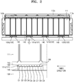
- FIG. 2 is a cross-sectional view taken along line A-A of FIG. 1
- FIG. 3 is an exploded perspective view illustrating elements of the battery pack shown in FIG. 1
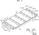
- FIG. 4 is a partial perspective view illustrating an assembled state of some elements of the battery pack shown in FIG. 3
- FIG. 5 is a plan view illustrating flows of a heat transfer medium in a cooling passage
- FIG. 6 is a plan view illustrating flows of a heat transfer medium in a cooling passage according to another embodiment of the cooling passage shown in FIG. 5 .
- the battery pack of the embodiment of the present disclosure may include a battery module 110, a cooling passage 120, a support member 130, elastic members 140, a thermally conductive plate 160, and a buffer pad 150.
- the battery module 110 may be a high-voltage, high-capacity battery module including a plurality of battery cells 111 electrically connected to each other.
- the battery cells 111 included in the battery module 110 may be arranged side by side in a third direction.
- embodiments of the present disclosure are not limited thereto. That is, the battery cells 111 may be arranged side by side in a first direction.
- the structure in which the battery cells 111 are arranged in the third direction will be mainly described.
- a plurality of battery modules 110 may be provided, and in this case, the battery modules 110 may be arranged side by side in the first direction (or a second direction).
- the first direction is a direction in which the heat transfer medium mainly flows in the cooling passage 120 (as described later, the heat transfer medium may also flow in the third direction through a turning passage 125 in addition to flowing in the first direction).
- FIG. 1 illustrates four battery modules 110 arranged in the first direction
- embodiments of the present disclosure are not limited to the illustrated number of battery modules 110. That is, a plurality of battery modules 110 may be provided.
- each of the battery modules 110 may further include a housing 112 that covers and seals the battery cells 111.
- the housing 112 may include opening holes 112h to open portions of lateral and front sides of the battery cells 111 such that heat generated in the battery cells 111 may be dissipated to the outside.
- the opening holes 112h shown in the drawings have a rectangular shape with curved corners, but embodiments of the present disclosure are not limited thereto.
- the opening holes 112h are for smoothly dissipating heat generated in the battery cells 111 to the outside, and to this end, the opening holes 112h may be formed in any shapes at any positions of the housing 112. For example, although not shown in the drawings, opening holes 112h may also be formed in an upper side of the housing 112.
- the housing 112 may include: a pair of end housings 112e facing wide sides of the battery cells 111; a pair of side housings 112s connected to the end housings 112e and facing lateral sides of the battery cells 111; and a cover housing 112c facing an upper side of the battery cells 111.
- the end housings 112e, the side housings 112s, and the cover housing 112c are for fixing the battery cells 111 to form the battery module 110, and may be variously shaped according to the design of the battery module 110.
- Each of the battery cells 111 may have a general structure including an electrode assembly (not shown) in which a positive electrode plate (not shown) and a negative electrode plate (not shown) are arranged at both sides of a separator (not shown), and may be charged with a preset amount of electricity and may be discharged.
- a first terminal (not shown) and a second terminal (not shown) may protrude from a side of each of the battery cells 111 at a given distance therebetween.
- the first terminal and the second terminal of a battery cell 111 may be electrically connected to the first terminal and the second terminal of an adjacent battery cell 111 via a bus bar (not shown).
- the first terminal and the second terminal may have a positive polarity and a negative polarity, respectively.
- the first terminals and the second terminals electrically connected through bus bars as described above may be configured as a positive terminal 113 or a negative terminal 114 of the battery module 110 as shown in the drawings and may be exposed to the outside of the housing 112. Although not shown in the drawings, the positive and negative terminals 113 and 114 of the battery modules 110 may be electrically connected to each other through bus bars that connect the battery modules 110.
- the cooling passage 120 may include a plurality of inflow tubes 121, a plurality of outflow tubes 122, a hub member 123, a hub passage 124, a turning passage 125, and ribs 126.
- the cooling passage 120 may be arranged adjacent to the battery modules 110 to cool the battery modules 110 using the heat transfer medium flowing in the cooling passage 120.
- the heat transfer medium may be a refrigerant capable of undergoing a phase change at room temperature and may include, for example, a CFC-based refrigerant such as R134a and R1234YF, and Novec. Any refrigerant, which is considered as being optimal for cooling the battery modules 110 in terms of physical factors such as the capacity and size of the battery pack and thermodynamic factors such as heat generated in the battery pack, may be selected as the heat transfer medium.
- FIG. 1 illustrates that the cooling passage 120 is provided on lower sides of the battery modules 110
- cooling passages 120 may also be provided on lateral sides and upper sides of the battery modules 110 based on the directions shown in the drawings.
- the housings 112, the positive terminals 113, the negative terminals 114, and the bus bars (not shown), which are main components when joining the battery cells 111 to each other, may be distant from the cooling passage 120 as shown in FIG. 1 .
- the following description will be given based on the structure in which the cooling passage 120 is provided on the lower sides of the battery modules 110 as shown in FIG. 1 .
- the inflow tubes 121 may be arranged adjacent to an imaginary line VL passing through the centers of the battery modules 110 in the first direction and may provide paths through which the heat transfer medium flows is introduced.
- the outflow tubes 122 may be arranged adjacent to the lateral sides of the battery modules 110 based on the first direction and may provide paths through which the heat transfer medium flows outward.
- the inflow tubes 121 may be provided as a pair, and the outflow tubes 122 may also be provided as a pair.
- an inflow tube 121 a provided on a side of the imaginary line VL and the other inflow tube 121b provided on the opposite side of the imaginary line VL may be arranged to be symmetrical to each other.
- an outflow tube 122a provided on a side of the imaginary line VL and the other outflow tube 122b provided on the opposite side of the imaginary line VL may be arranged to be symmetrical to each other.
- the inflow tubes 121 may be adjacent to the imaginary line VL than the outflow tubes 122 are to the imaginary line VL, and the outflow tubes 122 may be more distant from the imaginary line VL than the inflow tubes 121 are from the imaginary line VL, that is, closer to the lateral sides of the battery modules 110.
- the inflow tube 121a and the outflow tube 122a provided on the side of the imaginary line VL will be referred to as a first sub-inflow tube 121a and a first sub-outflow tube 122a, respectively, and the other inflow tube 121b and the other outflow tube 122b provided on the opposite side of the imaginary line VL will be referred to as a second sub-inflow tube 121b and a second sub-outflow tube 122b, respectively.
- the gap (not shown) between the first sub-inflow tube 121a and the first sub-outflow tube 122a, the gap (not shown) between the first sub-inflow tube 121a and the second sub-inflow tube 121b, and the gap (not shown) between the second sub-inflow tube 121b and the second sub-outflow tube 122b may correspond to each other. That is, the inflow tubes 121 and the outflow tubes 122 may be arranged at regular intervals.
- FIG. 6 is a view illustrating another embodiment of the inflow tubes 121 and the outflow tubes 122 shown in FIG. 5 .
- the gap (a) between a first sub-inflow tube 221a and a second sub-inflow tube 221b may be less than the gap (b) between the first sub-inflow tube 221a and a first sub-outflow tube 222a and the gap (b) between the second sub-inflow tube 221b and a second sub-outflow tube 222b.
- the gap (a) between the first sub-inflow tube 221a and the second sub-inflow tube 221b may be adjusted to be less than the gap (b) between the first sub-inflow tube 221a and the first sub-outflow tube 222a and the gap (b) between the second sub-inflow tube 221b and the second sub-outflow tube 222b because center portions of the battery modules 110 adjacent to the imaginary line VL generally have a higher temperature than the lateral sides of the battery modules 110.
- the effect obtainable when the inflow tubes 121 and 221 and the outflow tubes 122 and 222 shown in FIGS. 5 and 6 have such a structure will be described later in detail with reference to FIG. 7 .
- the heat transfer medium flows as follows. As shown in FIG. 5 , the heat transfer medium introduced into the cooling passage 120 may cool the battery modules 110 sequentially in the first direction (in the order of battery modules 110-1, 110-2, 110-3, and 110-4) while flowing along the inflow tubes 121. In detail, the heat transfer medium may flow in the first direction along the first sub-inflow tube 121a and the second sub-inflow tube 121b adjacent to the imaginary line VL.
- the heat transfer medium may be guided from the inflow tubes 121 to the outflow tubes 122, and then, while flowing along the outflow tubes 122 in the second direction opposite to the first direction, the heat transfer medium may sequentially cool the battery modules 110 (in the order of battery modules 110-4, 110-3, 110-2, and 110-1).
- the cooling passage 120 may further include the hub member 123 including an inlet 123a through which the heat transfer medium is introduced and an outlet 123b through which the heat transfer medium is discharged.
- the cooling passage 120 may correspond to the evaporator.
- the inlet 123a may be connected downstream of the expansion valve through a heat transfer medium tube (not shown), and the outlet 123b may be connected upstream of the compressor through a heat transfer medium tube (not shown).
- the heat transfer medium may be introduced into the cooling passage 120 through the inlet 123a in a low-temperature, low-pressure liquid state after passing through the expansion valve, and may then evaporate by absorbing heat from the battery modules 110 while flowing along the cooling passage 120.
- the flow characteristics of the heat transfer medium will be described in detail with reference to FIG. 7 .
- the hub member 123 may serve as a passage for delivering the heat transfer medium to the cooling passage 120, and specifically, the hub member 123 may also control the flow rate of the heat transfer medium flowing into the cooling passage 120. That is, although not shown in the drawings, the hub member 123 may be electrically connected to a controller (not shown) that includes hardware having a microprocessor and an electric circuit and software for driving the hardware, and the controller may control the opening and closing of the inlet 123a and the outlet 123b and the degree of opening of the inlet 123a and the outlet 123b.
- cooling passage 120 may further include a hub passage 124, and the hub passage 124 may include an inflow passage 124a configured to guide the heat transfer medium from the inlet 123a toward the inflow tubes 121 and an outflow passage 124b configured to guide the heat transfer medium from the outflow tubes 122 toward the outlet 123b.
- the hub passage 124 may further include first barrier walls 124c provided therein to isolate the inflow passage 124a and the outflow passage 124b from each other for preventing streams of the heat transfer medium flowing in the inflow passage 124a and streams of the heat transfer medium flowing in the outflow passage 124b from mixing with each other. That is, the first barrier walls 124c may physically isolate inner spaces of the inflow passage 124a and the outflow passage 124b from each other to prevent streams of the heat transfer medium introduced into the furthest upstream sides of the inflow tubes 121 from mixing with streams of the heat transfer medium flowing through the furthest downstream sides of the outflow tubes 122.
- cooling passage 120 may further include the turning passage 125 configured to connect the furthest downstream sides of the inflow tubes 121 and the furthest upstream sides of the outflow tubes 122 to each other while preventing the heat transfer medium from flowing between the inflow tubes 121 that are adjacent to the imaginary line VL.
- the turning passage 125 may include: a first sub-turning passage 125a through which the first sub-inflow tube 121a of the inflow tubes 121 arranged at a side of the imaginary line VL is connected to the first sub-outflow tube 122a of the outflow tubes 122 arranged at the side of the imaginary line VL; and a second sub-turning passage 125b through which the second sub-inflow tube 121b of the inflow tubes 121 arranged at the other side (opposite side) of the imaginary line VL is connected to the second sub-outflow tube 122b of the outflow tubes 122 arranged at the other side of the imaginary line VL.
- the first sub-turning passage 125a and the second sub-turning passage 125b may be formed in one piece.
- embodiments of the present disclosure are not limited thereto.
- the first sub-turning passage 125a and the second sub-turning passage 125b may be separate from each other as independent elements respectively connecting the first sub-inflow tube 121a to the first sub-outflow tube 122a, and the second sub-inflow tube 121b to the second sub-outflow tube 122b.
- the first sub-turning passage 125a and the second sub-turning passage 125b of the turning passage 125 may be formed in one piece in the third direction crossing the first and second directions.
- the turning passage 125 may further include a second barrier wall 125c provided therein to isolate the first sub-inflow tube 121a and the second sub-inflow tube 121b from each other such that a stream of the heat transfer medium flowing along the first sub-inflow tube 121a and reaching the furthest downstream side of the first sub-inflow tube 121a may not mix with a stream of the heat transfer medium flowing along the second sub-inflow tube 121b and reaching the furthest downstream side of the second sub-inflow tube 121b.
- a second barrier wall 125c provided therein to isolate the first sub-inflow tube 121a and the second sub-inflow tube 121b from each other such that a stream of the heat transfer medium flowing along the first sub-inflow tube 121a and reaching the furthest downstream side of the first sub-inflow tube 121a may not mix with a stream of the heat transfer medium flowing along the second sub-inflow tube 121b and reaching the furthest downstream side of the second sub-inflow tube 121b.
- the second barrier wall 125c is provided in the turning passage 125, the heat transfer medium passing through the furthest downstream side of the first sub-inflow tube 121a may turn toward the furthest upstream side of the first sub-outflow tube 122a along the first sub-turning passage 125a.
- the second barrier wall 125c is provided in the turning passage 125 formed in one-piece, the heat transfer medium passing through the furthest downstream side of the second sub-inflow tube 121b may turn toward the furthest upstream side of the second sub-outflow tube 122b along the second sub-turning passage 125b.
- the cooling passage 120 may further include the ribs 126 which extend in the cooling passage 120 in the first direction to divide the path of the heat transfer medium into a plurality of channels C1 to C9.
- the ribs 126 may be formed in the inflow tubes 121 and the outflow tubes 122 in the first direction in which the inflow tubes 121 and the outflow tubes 122 extend, to divide the inside of each of the inflow tubes 121 and the outflow tubes 122 into the plurality of channels C1 to C9.
- the support member 130 may support the battery modules 110 and the cooling passage 120 and may include a recessed portion 131 for receiving the cooling passage 120. That is, as shown in the drawings, the support member 130 is a basic skeleton that supports all components of the battery pack.
- the recessed portion 131 is formed by recessing, at predetermined intervals, a contact surface of the support member 130 with the cooling passage 120, and the elastic members 140 may be provided in the recessed portion 131.
- the elastic members 140 may be arranged between the cooling passage 120 and the support member 130 to elastically support the cooling passage 120.
- the elastic members 140 are for improving contact between the cooling passage 120 and the support member 130, and may have the same width as the cooling passage 120 such that the cooling passage 120 may be stably arranged at the support member 130.
- Buffer pads 150 may be arranged between the battery modules 110 and thermally conductive plates 160 to buffer and support sides of the battery modules 110, that is, the lower sides of the battery cells 111 as shown in FIG. 2 .
- the buffer pads 150 may be formed of a silicone-based material to minimize a tolerance between the battery modules 110 and the thermally conductive plates 160.
- the thermally conductive plates 160 may be arranged between the battery modules 110 and the cooling passage 120 to transfer heat generated from the battery modules 110 to the cooling passage 120. That is, the thermally conductive plates 160 may prevent direct contact between the battery modules 110 and the cooling passage 120 to protect the opposing surfaces of the battery modules 110 and the cooling passage 120. In detail, the thermally conductive plates 160 may be arranged between the cooling passage 120 and the buffer pads 150 supporting the battery modules 110 to mechanically connect the cooling passage 120 and the buffer pads 150 to each other.
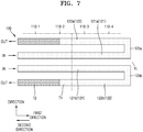
- FIG. 7 is a schematic view illustrating variations in the temperature of the heat transfer medium flowing in the cooling passage 120.
- the heat transfer medium introduced into the inflow tubes 121 may cool the center portions of the battery modules 110 adjacent to the imaginary line VL while flowing in the first direction along the first sub-inflow tube 121a and the second sub-inflow tube 121b, and may then flow to the outflow tubes 122 through the turning passage 125. After flowing from the turning passage 125 to the outflow tubes 122, the heat transfer medium may cool the lateral sides of the battery modules 110 while flowing in the second direction along the first sub-outflow tube 122a and the second sub-outflow tube 122b.
- the heat transfer medium may absorb heat generated in the battery modules 110 while flowing through the cooling passage 120, and may thus undergo a phase change at a certain temperature. After the evaporation of the heat transfer medium fully occurs, the heat transfer medium may be superheated while the temperature of the heat transfer medium is rapidly increased. Referring to the temperature distribution of the heat transfer medium shown in FIG. 7 by considering the above-described characteristics, when the temperature of the heat transfer medium introduced into the inflow tubes 121 is defined as T1, and the temperature of the heat transfer medium flowing out of the outflow tubes 122 is defined as T2, T2 may be higher than T1.
- the heat transfer medium introduced into the cooling passage 120 may initially undergo a phase change at the constant temperature T1, and may sufficiently evaporate at a position adjacent to the outlet 123b (refer to FIG. 5 ) and may then be superheated while the temperature of the heat transfer medium is rapidly increased to the temperature T2 higher than the temperature T1.
- the temperature of the battery modules 110 may be highest at the center portions of the battery modules 110 and lowest at the lateral sides of the battery modules 110.
- the reason for this is as follows. Central battery cells 111 exchange heat with adjacent battery cells 111, and each lateral battery cell 111 is in not contact with another battery cell 111 at one side thereof. Thus, heat may not be smoothly dissipated from the central battery cells 111 to the outside while the central battery cells 111 exchange heat with each other, but heat may be naturally dissipated from the lateral battery cells 111 to the outside by natural convection because the lateral battery cells 111 are exposed to the outside through the opening holes 112h formed in the housings 112.
- the temperature of the battery modules 110 each including the battery cells 111 is structurally higher at the center portions of the battery modules 110 than at the lateral sides of the battery modules 110. Therefore, in the embodiments of the present disclosure, the first sub-inflow tube 121a and the second sub-inflow tube 121b are arranged at positions adjacent to the imaginary line VL passing through the centers of the battery modules 110 in the first direction, and the first sub-outflow tube 122a and the second sub-outflow tube 122b are arranged at positions adjacent to the lateral sides of the battery modules 110.
- the center portions of the battery modules 110 having a relatively high temperature may be cooled by the heat transfer medium having the relatively low temperature T1
- the lateral sides of the battery modules 110 having a relatively low temperature may be cooled by the heat transfer medium having the relatively high temperature T2. Therefore, the effect of uniformly cooling the entire regions of the battery modules 110 may be maximized.
- the cooling passage 120 has a parallel structure including two inflow tubes 121 and two outflow tubes 122.
- the overall length of the cooling passage 120 may be reduced compared to the case in which the cooling passage 120 has a series structure. According to this structure, the difference between the pressure of the heat transfer medium when the heat transfer medium is introduced into the cooling passage 120 and the pressure of the heat transfer medium when the heat transfer medium is discharge from the cooling passage 120 may be maintained at a low value, and thus the efficiency of the compressor that compresses the heat transfer medium may be improved.
- the entire area of the battery modules of the battery pack may be uniformly cooled according to the embodiments of the present disclosure.
Landscapes
- Chemical & Material Sciences (AREA)
- Chemical Kinetics & Catalysis (AREA)
- Electrochemistry (AREA)
- General Chemical & Material Sciences (AREA)
- Engineering & Computer Science (AREA)
- Manufacturing & Machinery (AREA)
- Secondary Cells (AREA)
- Battery Mounting, Suspending (AREA)
Abstract
Description
- Embodiments of the present disclosure relate to a battery pack, and more particularly, to a battery pack having improved heat exchange efficiency.
- In general, battery cells are used as energy sources for mobile devices, electric vehicles, hybrid vehicles, or other electric devices, and such battery cells may be modified according to the types of devices to which the battery cells are applied.
- For example, small mobile devices such as cellular phones may be operated for a certain period of time by using the power and capacity of only one battery cell. However, high-capacity battery modules each formed by electrically connecting battery cells to increase power and capacity may be used for devices such as electric vehicles or hybrid vehicles consuming large amounts of power, having long operating times, and requiring high-power driving.
- The output power or current of such a battery module may be adjusted by varying the number of battery cells of the battery module. In addition, such battery modules may be electrically connected to each other to form a battery pack.
- In general, battery cells provide energy to external electronic devices while undergoing an electrochemical reaction. The battery cells generate heat during the electrochemical reaction, and when such heat accumulates, the battery cells may deteriorate and may, in severe cases, cause problems with battery pack safety. Therefore, various studies have been conducted to control the temperature of battery cells.
- The above-described background art is technical information that the inventors had or learned when or while deriving embodiments of the present disclosure and may not have been publicly known before the filing of the present patent application.
- Embodiments of the present disclosure provide a battery pack configured to uniformly cool the entire area of battery modules.
- In addition, embodiments of the present disclosure provide a battery pack configured to improve the efficiency of a compressor which compresses a heat transfer medium used to cool battery modules of the battery pack.
- An embodiment of the present disclosure provides a battery pack including: a plurality of battery modules each including a plurality of battery cells; and a cooling passage arranged adjacent to the plurality of battery modules and configured to cool the plurality of battery modules using a heat transfer medium flowing in the cooling passage, wherein the plurality of battery modules are arranged side by side in a first direction, and the cooling passage includes: a plurality of inflow tubes arranged adjacent to an imaginary line passing through centers of the plurality of battery modules in the first direction and providing paths into which the heat transfer medium is introduced; and a plurality of outflow tubes connected to furthest downstream sides of the plurality of inflow tubes and arranged adjacent to lateral sides of the plurality of battery modules based on the first direction, the plurality of outflow tubes providing paths through which the heat transfer medium is discharged.
- According to the battery pack of the embodiments of the present disclosure, a portion of the cooling passage in which the heat transfer medium is superheated is arranged at low-temperature portions of the battery modules, and thus the entire area of the battery modules may be uniformly cooled.
- In addition, according to the battery pack of the embodiments of the present disclosure, the cooling passage has a parallel arrangement, and thus the overall length of the cooling passage may be reduced to maintain the difference between the inflow pressure and outflow pressure of the heat transfer medium at a low value, and thus to improve the efficiency of a compressor used to compress the heat transfer medium.
- However, the scope of the present disclosure is not limited to these effects.
-
-
FIG. 1 is a perspective view illustrating a battery pack according to an embodiment of the present disclosure. -
FIG. 2 is a cross-sectional view taken along line A-A ofFIG. 1 . -
FIG. 3 is an exploded perspective view illustrating elements of the battery pack shown inFIG. 1 . -
FIG. 4 is a partial perspective view illustrating an assembled state of some elements of the battery pack shown inFIG. 3 . -
FIG. 5 is a plan view illustrating flows of a heat transfer medium in a cooling passage. -
FIG. 6 is a plan view illustrating flows of a heat transfer medium in a cooling passage according to another embodiment of the cooling passage shown inFIG. 5 . -
FIG. 7 is a schematic view illustrating variations in the temperature of a heat transfer medium flowing in a cooling passage. - An embodiment of the present disclosure provides a battery pack including: a plurality of battery modules each including a plurality of battery cells; and a cooling passage arranged adjacent to the plurality of battery modules and configured to cool the plurality of battery modules using a heat transfer medium flowing in the cooling passage, wherein the plurality of battery modules are arranged side by side in a first direction, and the cooling passage includes: a plurality of inflow tubes arranged adjacent to an imaginary line passing through centers of the plurality of battery modules in the first direction and providing paths into which the heat transfer medium is introduced; and a plurality of outflow tubes connected to furthest downstream sides of the plurality of inflow tubes and arranged adjacent to lateral sides of the plurality of battery modules based on the first direction, the plurality of outflow tubes providing paths through which the heat transfer medium is discharged.
- In the embodiment, the heat transfer medium may sequentially cool the plurality of battery modules in the first direction while flowing along the plurality of inflow tubes, and may then be guided from the plurality of inflow tubes to the plurality of outflow tubes and may sequentially cool the plurality of battery modules in a second direction opposite to the first direction while flowing along the plurality of outflow tubes.
- In the embodiment, the cooling passage may include: a hub member including an inlet through which the heat transfer medium is introduced and an outlet through which the heat transfer medium is discharged; a hub passage including an inflow passage configured to guide the heat transfer medium introduced through the inlet toward the plurality of inflow tubes, and an outflow passage configured to guide the heat transfer medium from the plurality of outflow tubes toward the outlet; and a turning passage connecting the furthest downstream sides of the plurality of inflow tubes to furthest upstream sides of the plurality of outflow tubes while separating streams of the heat transfer medium flowing in the plurality of inflow tubes adjacent to the imaginary line from each other.
- In the embodiment, the hub passage may further include a first barrier wall provided in the hub passage to isolate the inflow passage and the outflow passage from each other for preventing a stream of the heat transfer medium flowing in the inflow passage and a stream of the heat transfer medium flowing in the outflow passage from mixing with each other.
- In the embodiment, the turning passage may include: a first sub-turning passage connecting a first sub-inflow tube among the plurality of inflow tubes, the first sub-inflow tube being arranged at a side of the imaginary line, to a first sub-outflow tube among the plurality of outflow tubes, the first sub-outflow tube being arranged at the side of the imaginary line; and a second sub-turning passage connecting a second sub-inflow tube among the plurality of inflow tubes, the second sub-inflow tube being arranged at an opposite side of the imaginary line, to a second sub-outflow tube among the plurality of outflow tubes, the second sub-outflow tube being arranged at the opposite side of the imaginary line.
- In the embodiment, the turning passage may be provided in one piece in a third direction crossing the first direction and a second direction opposite to the first direction, and the turning passage may further include a second barrier wall provided in the turning passage and configured to isolate a first sub-inflow tube that is is one of the plurality of inflow tubes arranged at a side of the imaginary line, from a second sub-inflow tube that is one of the plurality of inflow tubes arranged at an opposite side of the imaginary line, to prevent a stream of the heat transfer medium flowing in the first sub-inflow tube from mixing with a stream of the heat transfer medium flowing in the second sub-inflow tube.
- In the embodiment, the plurality of inflow tubes and the plurality of outflow tubes may be symmetrical with respect to the imaginary line.
- In the embodiment, a gap between a first sub-inflow tube among the plurality of inflow tubes, the first sub-inflow tube being arranged at a side of the imaginary line, and a second sub-inflow tube among the plurality of inflow tubes, the second sub-inflow tube being arranged at an opposite side of the imaginary line, may be less than a gap between the first sub-inflow tube and a first sub-outflow tube among the plurality of outflow tubes, the first sub-outflow tube being arranged at the side of the imaginary line and a gap between the second sub-inflow tube and a second sub-outflow tube among the plurality of outflow tubes, the second sub-outflow tube being arranged at the opposite side of the imaginary line.
- In the embodiment, the battery pack may further include a support member configured to support the plurality of battery modules and the cooling passage and including a recessed portion to receive the cooling passage.
- In the embodiment, the battery pack may further include an elastic member provided on the recessed portion between the cooling passage and the support member and elastically supporting the cooling passage.
- In the embodiment, the battery pack may further include a thermally conductive plate arranged between the cooling passage and the plurality of battery modules and transferring heat generated in the plurality of battery modules to the cooling passage.
- In the embodiment, the battery pack may further include a buffer pad arranged between the thermally conductive plate and the plurality of battery modules to buffer and support sides of the plurality of battery modules.
- In the embodiment, the cooling passage may further include a rib extending in the cooling passage in the first direction and dividing a path of the heat transfer medium into a plurality of channels.
- In the embodiment, the heat transfer medium may be a refrigerant capable of undergoing a phase change at room temperature.
- Other aspects, characteristics, and advantages will become apparent and more readily appreciated from the accompanying drawings, claims, and detailed description.
- The present disclosure may be variously modified, and various embodiments may be provided according to the present disclosure. Hereinafter, some embodiments will be illustrated in the accompanying drawings and described in detail. Effects and features of the present disclosure, and implementation methods thereof will be clarified through the following embodiments described in detail with reference to the accompanying drawings. However, the present disclosure is not limited to the following embodiments but may be implemented in various forms.
- In the following embodiments, it will be understood that although terms such "first" and "second," are used to describe various elements, these elements should not be limited by these terms. These terms are only used to distinguish one element from another. The terms of a singular form may include plural forms unless referred to the contrary. In addition, terms such as "include" or "comprise" specify features or the presence of stated elements, but do not exclude other features or elements.
- In the drawings, the sizes of elements may be exaggerated for clarity. For example, in the drawings, the size or thickness of each element may be arbitrarily shown for illustrative purposes, and thus the present disclosure should not be construed as being limited thereto.
- Hereinafter, embodiments of the present disclosure will be described in detail with reference to the accompanying drawings. In the following description given with reference to the accompanying drawings, the same elements or corresponding elements are denoted with the same reference numerals, and overlapping descriptions thereof will be omitted.
-
FIG. 1 is a perspective view illustrating a battery pack according to an embodiment of the present disclosure;FIG. 2 is a cross-sectional view taken along line A-A ofFIG. 1 ;FIG. 3 is an exploded perspective view illustrating elements of the battery pack shown inFIG. 1 ;FIG. 4 is a partial perspective view illustrating an assembled state of some elements of the battery pack shown inFIG. 3 ;FIG. 5 is a plan view illustrating flows of a heat transfer medium in a cooling passage; andFIG. 6 is a plan view illustrating flows of a heat transfer medium in a cooling passage according to another embodiment of the cooling passage shown inFIG. 5 . - First, referring to
FIGS. 1 to 3 , the battery pack of the embodiment of the present disclosure may include abattery module 110, acooling passage 120, asupport member 130,elastic members 140, a thermallyconductive plate 160, and abuffer pad 150. - First, the
battery module 110 may be a high-voltage, high-capacity battery module including a plurality ofbattery cells 111 electrically connected to each other. For example, as shown inFIG. 1 , thebattery cells 111 included in thebattery module 110 may be arranged side by side in a third direction. However, embodiments of the present disclosure are not limited thereto. That is, thebattery cells 111 may be arranged side by side in a first direction. However, for ease of description, the structure in which thebattery cells 111 are arranged in the third direction will be mainly described. - In addition, a plurality of
battery modules 110 may be provided, and in this case, thebattery modules 110 may be arranged side by side in the first direction (or a second direction). The first direction is a direction in which the heat transfer medium mainly flows in the cooling passage 120 (as described later, the heat transfer medium may also flow in the third direction through aturning passage 125 in addition to flowing in the first direction). For example, althoughFIG. 1 illustrates fourbattery modules 110 arranged in the first direction, embodiments of the present disclosure are not limited to the illustrated number ofbattery modules 110. That is, a plurality ofbattery modules 110 may be provided. - In addition, each of the
battery modules 110 may further include ahousing 112 that covers and seals thebattery cells 111. Here, thehousing 112 may include openingholes 112h to open portions of lateral and front sides of thebattery cells 111 such that heat generated in thebattery cells 111 may be dissipated to the outside. The opening holes 112h shown in the drawings have a rectangular shape with curved corners, but embodiments of the present disclosure are not limited thereto. As described above, the opening holes 112h are for smoothly dissipating heat generated in thebattery cells 111 to the outside, and to this end, the openingholes 112h may be formed in any shapes at any positions of thehousing 112. For example, although not shown in the drawings, openingholes 112h may also be formed in an upper side of thehousing 112. - In detail, the
housing 112 may include: a pair ofend housings 112e facing wide sides of thebattery cells 111; a pair ofside housings 112s connected to theend housings 112e and facing lateral sides of thebattery cells 111; and acover housing 112c facing an upper side of thebattery cells 111. Theend housings 112e, theside housings 112s, and thecover housing 112c are for fixing thebattery cells 111 to form thebattery module 110, and may be variously shaped according to the design of thebattery module 110. - Each of the
battery cells 111 may have a general structure including an electrode assembly (not shown) in which a positive electrode plate (not shown) and a negative electrode plate (not shown) are arranged at both sides of a separator (not shown), and may be charged with a preset amount of electricity and may be discharged. In addition, a first terminal (not shown) and a second terminal (not shown) may protrude from a side of each of thebattery cells 111 at a given distance therebetween. - The first terminal and the second terminal of a
battery cell 111 may be electrically connected to the first terminal and the second terminal of anadjacent battery cell 111 via a bus bar (not shown). Here, the first terminal and the second terminal may have a positive polarity and a negative polarity, respectively. - The first terminals and the second terminals electrically connected through bus bars as described above may be configured as a
positive terminal 113 or anegative terminal 114 of thebattery module 110 as shown in the drawings and may be exposed to the outside of thehousing 112. Although not shown in the drawings, the positive andnegative terminals battery modules 110 may be electrically connected to each other through bus bars that connect thebattery modules 110. - Next, the
cooling passage 120 may include a plurality ofinflow tubes 121, a plurality ofoutflow tubes 122, ahub member 123, ahub passage 124, aturning passage 125, andribs 126. - The
cooling passage 120 may be arranged adjacent to thebattery modules 110 to cool thebattery modules 110 using the heat transfer medium flowing in thecooling passage 120. Herein, the heat transfer medium may be a refrigerant capable of undergoing a phase change at room temperature and may include, for example, a CFC-based refrigerant such as R134a and R1234YF, and Novec. Any refrigerant, which is considered as being optimal for cooling thebattery modules 110 in terms of physical factors such as the capacity and size of the battery pack and thermodynamic factors such as heat generated in the battery pack, may be selected as the heat transfer medium. - In addition, although
FIG. 1 illustrates that thecooling passage 120 is provided on lower sides of thebattery modules 110, embodiments of the present disclosure are not limited thereto. For example, coolingpassages 120 may also be provided on lateral sides and upper sides of thebattery modules 110 based on the directions shown in the drawings. In this case, however, thehousings 112, thepositive terminals 113, thenegative terminals 114, and the bus bars (not shown), which are main components when joining thebattery cells 111 to each other, may be distant from thecooling passage 120 as shown inFIG. 1 . For ease of description, the following description will be given based on the structure in which thecooling passage 120 is provided on the lower sides of thebattery modules 110 as shown inFIG. 1 . - The
inflow tubes 121 may be arranged adjacent to an imaginary line VL passing through the centers of thebattery modules 110 in the first direction and may provide paths through which the heat transfer medium flows is introduced. In addition, theoutflow tubes 122 may be arranged adjacent to the lateral sides of thebattery modules 110 based on the first direction and may provide paths through which the heat transfer medium flows outward. - Hereinafter, the structures of the
inflow tubes 121 and theoutflow tubes 122 will be described in detail with reference toFIGS. 5 and6 . - First, Referring to
FIG. 5 , along the imaginary line VL, theinflow tubes 121 may be provided as a pair, and theoutflow tubes 122 may also be provided as a pair. In this case, aninflow tube 121 a provided on a side of the imaginary line VL and theother inflow tube 121b provided on the opposite side of the imaginary line VL may be arranged to be symmetrical to each other. In addition, anoutflow tube 122a provided on a side of the imaginary line VL and theother outflow tube 122b provided on the opposite side of the imaginary line VL may be arranged to be symmetrical to each other. In this case, theinflow tubes 121 may be adjacent to the imaginary line VL than theoutflow tubes 122 are to the imaginary line VL, and theoutflow tubes 122 may be more distant from the imaginary line VL than theinflow tubes 121 are from the imaginary line VL, that is, closer to the lateral sides of thebattery modules 110. - Hereinafter, the
inflow tube 121a and theoutflow tube 122a provided on the side of the imaginary line VL will be referred to as a firstsub-inflow tube 121a and a firstsub-outflow tube 122a, respectively, and theother inflow tube 121b and theother outflow tube 122b provided on the opposite side of the imaginary line VL will be referred to as a secondsub-inflow tube 121b and a secondsub-outflow tube 122b, respectively. - In detail, as shown in
FIG. 5 , the gap (not shown) between the firstsub-inflow tube 121a and the firstsub-outflow tube 122a, the gap (not shown) between the firstsub-inflow tube 121a and the secondsub-inflow tube 121b, and the gap (not shown) between the secondsub-inflow tube 121b and the secondsub-outflow tube 122b may correspond to each other. That is, theinflow tubes 121 and theoutflow tubes 122 may be arranged at regular intervals. - In addition,
FIG. 6 is a view illustrating another embodiment of theinflow tubes 121 and theoutflow tubes 122 shown inFIG. 5 . Referring toFIG. 6 , the gap (a) between a firstsub-inflow tube 221a and a secondsub-inflow tube 221b may be less than the gap (b) between the firstsub-inflow tube 221a and a firstsub-outflow tube 222a and the gap (b) between the secondsub-inflow tube 221b and a secondsub-outflow tube 222b. - As described above, the gap (a) between the first
sub-inflow tube 221a and the secondsub-inflow tube 221b may be adjusted to be less than the gap (b) between the firstsub-inflow tube 221a and the firstsub-outflow tube 222a and the gap (b) between the secondsub-inflow tube 221b and the secondsub-outflow tube 222b because center portions of thebattery modules 110 adjacent to the imaginary line VL generally have a higher temperature than the lateral sides of thebattery modules 110. The effect obtainable when theinflow tubes 121 and 221 and theoutflow tubes 122 and 222 shown inFIGS. 5 and6 have such a structure will be described later in detail with reference toFIG. 7 . - In addition, the heat transfer medium flows as follows. As shown in
FIG. 5 , the heat transfer medium introduced into thecooling passage 120 may cool thebattery modules 110 sequentially in the first direction (in the order of battery modules 110-1, 110-2, 110-3, and 110-4) while flowing along theinflow tubes 121. In detail, the heat transfer medium may flow in the first direction along the firstsub-inflow tube 121a and the secondsub-inflow tube 121b adjacent to the imaginary line VL. - After the heat transfer medium flows along the first
sub-inflow tube 121a and the secondsub-inflow tube 121b and reaches the furthest downstream sides of theinflow tubes 121, the heat transfer medium may be guided from theinflow tubes 121 to theoutflow tubes 122, and then, while flowing along theoutflow tubes 122 in the second direction opposite to the first direction, the heat transfer medium may sequentially cool the battery modules 110 (in the order of battery modules 110-4, 110-3, 110-2, and 110-1). - The structure of the
cooling passage 120 will now be described in more detail. - The
cooling passage 120 may further include thehub member 123 including aninlet 123a through which the heat transfer medium is introduced and anoutlet 123b through which the heat transfer medium is discharged. - In detail, among a compressor, a condenser, an expansion valve, and an evaporator forming a general refrigeration cycle, the
cooling passage 120 may correspond to the evaporator. In this case, although not shown in the drawings, theinlet 123a may be connected downstream of the expansion valve through a heat transfer medium tube (not shown), and theoutlet 123b may be connected upstream of the compressor through a heat transfer medium tube (not shown). - In this structure, the heat transfer medium may be introduced into the
cooling passage 120 through theinlet 123a in a low-temperature, low-pressure liquid state after passing through the expansion valve, and may then evaporate by absorbing heat from thebattery modules 110 while flowing along thecooling passage 120. The flow characteristics of the heat transfer medium will be described in detail with reference toFIG. 7 . - That is, the
hub member 123 may serve as a passage for delivering the heat transfer medium to thecooling passage 120, and specifically, thehub member 123 may also control the flow rate of the heat transfer medium flowing into thecooling passage 120. That is, although not shown in the drawings, thehub member 123 may be electrically connected to a controller (not shown) that includes hardware having a microprocessor and an electric circuit and software for driving the hardware, and the controller may control the opening and closing of theinlet 123a and theoutlet 123b and the degree of opening of theinlet 123a and theoutlet 123b. - In addition, the
cooling passage 120 may further include ahub passage 124, and thehub passage 124 may include aninflow passage 124a configured to guide the heat transfer medium from theinlet 123a toward theinflow tubes 121 and anoutflow passage 124b configured to guide the heat transfer medium from theoutflow tubes 122 toward theoutlet 123b. - In addition, the
hub passage 124 may further includefirst barrier walls 124c provided therein to isolate theinflow passage 124a and theoutflow passage 124b from each other for preventing streams of the heat transfer medium flowing in theinflow passage 124a and streams of the heat transfer medium flowing in theoutflow passage 124b from mixing with each other. That is, thefirst barrier walls 124c may physically isolate inner spaces of theinflow passage 124a and theoutflow passage 124b from each other to prevent streams of the heat transfer medium introduced into the furthest upstream sides of theinflow tubes 121 from mixing with streams of the heat transfer medium flowing through the furthest downstream sides of theoutflow tubes 122. - In addition, the
cooling passage 120 may further include theturning passage 125 configured to connect the furthest downstream sides of theinflow tubes 121 and the furthest upstream sides of theoutflow tubes 122 to each other while preventing the heat transfer medium from flowing between theinflow tubes 121 that are adjacent to the imaginary line VL. - In detail, the
turning passage 125 may include: a firstsub-turning passage 125a through which the firstsub-inflow tube 121a of theinflow tubes 121 arranged at a side of the imaginary line VL is connected to the firstsub-outflow tube 122a of theoutflow tubes 122 arranged at the side of the imaginary line VL; and a secondsub-turning passage 125b through which the secondsub-inflow tube 121b of theinflow tubes 121 arranged at the other side (opposite side) of the imaginary line VL is connected to the secondsub-outflow tube 122b of theoutflow tubes 122 arranged at the other side of the imaginary line VL. - Here, for example, as shown in
FIG. 5 , the firstsub-turning passage 125a and the secondsub-turning passage 125b may be formed in one piece. However, embodiments of the present disclosure are not limited thereto. For example, as schematically shown inFIG. 7 , the firstsub-turning passage 125a and the secondsub-turning passage 125b may be separate from each other as independent elements respectively connecting the firstsub-inflow tube 121a to the firstsub-outflow tube 122a, and the secondsub-inflow tube 121b to the secondsub-outflow tube 122b. - However, for ease of description, the following description will be given mainly based on the case in which the first
sub-turning passage 125a and the secondsub-turning passage 125b of theturning passage 125 are formed in one piece as shown inFIG. 5 . - As shown in
FIG. 5 , the firstsub-turning passage 125a and the secondsub-turning passage 125b of theturning passage 125 may be formed in one piece in the third direction crossing the first and second directions. - In this case, the
turning passage 125 may further include asecond barrier wall 125c provided therein to isolate the firstsub-inflow tube 121a and the secondsub-inflow tube 121b from each other such that a stream of the heat transfer medium flowing along the firstsub-inflow tube 121a and reaching the furthest downstream side of the firstsub-inflow tube 121a may not mix with a stream of the heat transfer medium flowing along the secondsub-inflow tube 121b and reaching the furthest downstream side of the secondsub-inflow tube 121b. - As described above, since the
second barrier wall 125c is provided in theturning passage 125, the heat transfer medium passing through the furthest downstream side of the firstsub-inflow tube 121a may turn toward the furthest upstream side of the firstsub-outflow tube 122a along the firstsub-turning passage 125a. Similarly, since thesecond barrier wall 125c is provided in theturning passage 125 formed in one-piece, the heat transfer medium passing through the furthest downstream side of the secondsub-inflow tube 121b may turn toward the furthest upstream side of the secondsub-outflow tube 122b along the secondsub-turning passage 125b. - Referring again to
FIG. 2 , thecooling passage 120 may further include theribs 126 which extend in thecooling passage 120 in the first direction to divide the path of the heat transfer medium into a plurality of channels C1 to C9. - That is, the
ribs 126 may be formed in theinflow tubes 121 and theoutflow tubes 122 in the first direction in which theinflow tubes 121 and theoutflow tubes 122 extend, to divide the inside of each of theinflow tubes 121 and theoutflow tubes 122 into the plurality of channels C1 to C9. - The
support member 130 may support thebattery modules 110 and thecooling passage 120 and may include a recessedportion 131 for receiving thecooling passage 120. That is, as shown in the drawings, thesupport member 130 is a basic skeleton that supports all components of the battery pack. - The recessed
portion 131 is formed by recessing, at predetermined intervals, a contact surface of thesupport member 130 with thecooling passage 120, and theelastic members 140 may be provided in the recessedportion 131. - That is, the
elastic members 140 may be arranged between thecooling passage 120 and thesupport member 130 to elastically support thecooling passage 120. In detail, theelastic members 140 are for improving contact between thecooling passage 120 and thesupport member 130, and may have the same width as thecooling passage 120 such that thecooling passage 120 may be stably arranged at thesupport member 130. -
Buffer pads 150 may be arranged between thebattery modules 110 and thermallyconductive plates 160 to buffer and support sides of thebattery modules 110, that is, the lower sides of thebattery cells 111 as shown inFIG. 2 . For example, thebuffer pads 150 may be formed of a silicone-based material to minimize a tolerance between thebattery modules 110 and the thermallyconductive plates 160. - The thermally
conductive plates 160 may be arranged between thebattery modules 110 and thecooling passage 120 to transfer heat generated from thebattery modules 110 to thecooling passage 120. That is, the thermallyconductive plates 160 may prevent direct contact between thebattery modules 110 and thecooling passage 120 to protect the opposing surfaces of thebattery modules 110 and thecooling passage 120. In detail, the thermallyconductive plates 160 may be arranged between thecooling passage 120 and thebuffer pads 150 supporting thebattery modules 110 to mechanically connect thecooling passage 120 and thebuffer pads 150 to each other. - Hereinafter, the cooling operation of the
cooling passage 120 of the battery pack described above according to the embodiments of the present disclosure will be described in more detail with reference toFIG. 7 . -
FIG. 7 is a schematic view illustrating variations in the temperature of the heat transfer medium flowing in thecooling passage 120. - Referring to
FIG. 7 , the heat transfer medium introduced into theinflow tubes 121 may cool the center portions of thebattery modules 110 adjacent to the imaginary line VL while flowing in the first direction along the firstsub-inflow tube 121a and the secondsub-inflow tube 121b, and may then flow to theoutflow tubes 122 through theturning passage 125. After flowing from theturning passage 125 to theoutflow tubes 122, the heat transfer medium may cool the lateral sides of thebattery modules 110 while flowing in the second direction along the firstsub-outflow tube 122a and the secondsub-outflow tube 122b. - As described above, the heat transfer medium may absorb heat generated in the
battery modules 110 while flowing through thecooling passage 120, and may thus undergo a phase change at a certain temperature. After the evaporation of the heat transfer medium fully occurs, the heat transfer medium may be superheated while the temperature of the heat transfer medium is rapidly increased. Referring to the temperature distribution of the heat transfer medium shown inFIG. 7 by considering the above-described characteristics, when the temperature of the heat transfer medium introduced into theinflow tubes 121 is defined as T1, and the temperature of the heat transfer medium flowing out of theoutflow tubes 122 is defined as T2, T2 may be higher than T1. That is, the heat transfer medium introduced into thecooling passage 120 may initially undergo a phase change at the constant temperature T1, and may sufficiently evaporate at a position adjacent to theoutlet 123b (refer toFIG. 5 ) and may then be superheated while the temperature of the heat transfer medium is rapidly increased to the temperature T2 higher than the temperature T1. - In addition, when the
battery cells 111 are arranged side by side in thebattery modules 110, the temperature of thebattery modules 110 may be highest at the center portions of thebattery modules 110 and lowest at the lateral sides of thebattery modules 110. The reason for this is as follows.Central battery cells 111 exchange heat withadjacent battery cells 111, and eachlateral battery cell 111 is in not contact with anotherbattery cell 111 at one side thereof. Thus, heat may not be smoothly dissipated from thecentral battery cells 111 to the outside while thecentral battery cells 111 exchange heat with each other, but heat may be naturally dissipated from thelateral battery cells 111 to the outside by natural convection because thelateral battery cells 111 are exposed to the outside through the opening holes 112h formed in thehousings 112. - As described above, the temperature of the
battery modules 110 each including thebattery cells 111 is structurally higher at the center portions of thebattery modules 110 than at the lateral sides of thebattery modules 110. Therefore, in the embodiments of the present disclosure, the firstsub-inflow tube 121a and the secondsub-inflow tube 121b are arranged at positions adjacent to the imaginary line VL passing through the centers of thebattery modules 110 in the first direction, and the firstsub-outflow tube 122a and the secondsub-outflow tube 122b are arranged at positions adjacent to the lateral sides of thebattery modules 110. Then, the center portions of thebattery modules 110 having a relatively high temperature may be cooled by the heat transfer medium having the relatively low temperature T1, and the lateral sides of thebattery modules 110 having a relatively low temperature may be cooled by the heat transfer medium having the relatively high temperature T2. Therefore, the effect of uniformly cooling the entire regions of thebattery modules 110 may be maximized. - In addition, referring to
FIG. 7 , thecooling passage 120 has a parallel structure including twoinflow tubes 121 and twooutflow tubes 122. In this case, the overall length of thecooling passage 120 may be reduced compared to the case in which thecooling passage 120 has a series structure. According to this structure, the difference between the pressure of the heat transfer medium when the heat transfer medium is introduced into thecooling passage 120 and the pressure of the heat transfer medium when the heat transfer medium is discharge from thecooling passage 120 may be maintained at a low value, and thus the efficiency of the compressor that compresses the heat transfer medium may be improved. - While embodiments of the present disclosure have been described with reference to the accompanying drawings, these embodiments are for illustrative purposes only, and it will be understood by those of ordinary skill in the art that various changes and modifications may be made therefrom. Therefore, the scope and spirit of the present disclosure should be defined by the following claims.
- As described above, the entire area of the battery modules of the battery pack may be uniformly cooled according to the embodiments of the present disclosure.
Claims (14)
- A battery pack comprising:a plurality of battery modules each comprising a plurality of battery cells; anda cooling passage arranged adjacent to the plurality of battery modules and configured to cool the plurality of battery modules using a heat transfer medium flowing in the cooling passage,wherein the plurality of battery modules are arranged side by side in a first direction, andthe cooling passage comprises:a plurality of inflow tubes arranged adjacent to an imaginary line passing through centers of the plurality of battery modules in the first direction and providing paths into which the heat transfer medium is introduced; anda plurality of outflow tubes connected to furthest downstream sides of the plurality of inflow tubes and arranged adjacent to lateral sides of the plurality of battery modules based on the first direction, the plurality of outflow tubes providing paths through which the heat transfer medium is discharged.
- The battery pack of claim 1, wherein the heat transfer medium sequentially cools the plurality of battery modules in the first direction while flowing along the plurality of inflow tubes, and is then guided from the plurality of inflow tubes to the plurality of outflow tubes and sequentially cools the plurality of battery modules in a second direction opposite to the first direction while flowing along the plurality of outflow tubes.
- The battery pack of claim 1, wherein the cooling passage comprises:a hub member comprising an inlet through which the heat transfer medium is introduced and an outlet through which the heat transfer medium is discharged;a hub passage comprising an inflow passage configured to guide the heat transfer medium introduced through the inlet toward the plurality of inflow tubes, and an outflow passage configured to guide the heat transfer medium from the plurality of outflow tubes toward the outlet; anda turning passage connecting the furthest downstream sides of the plurality of inflow tubes to furthest upstream sides of the plurality of outflow tubes while separating streams of the heat transfer medium flowing in the plurality of inflow tubes adjacent to the imaginary line from each other.
- The battery pack of claim 3, wherein the hub passage further comprises a first barrier wall provided in the hub passage to isolate the inflow passage and the outflow passage from each other for preventing a stream of the heat transfer medium flowing in the inflow passage and a stream of the heat transfer medium flowing in the outflow passage from mixing with each other.
- The battery pack of claim 3, wherein the turning passage comprises:a first sub-turning passage connecting a first sub-inflow tube among the plurality of inflow tubes, the first sub-inflow tube being arranged at a side of the imaginary line, to a first sub-outflow tube among the plurality of outflow tubes, the first sub-outflow tube being arranged at the side of the imaginary line; anda second sub-turning passage connecting a second sub-inflow tube among the plurality of inflow tubes, the second sub-inflow tube being arranged at an opposite side of the imaginary line, to a second sub-outflow tube among the plurality of outflow tubes, the second sub-outflow tube being arranged at the opposite side of the imaginary line.
- The battery pack of claim 3, wherein the turning passage is provided in one piece in a third direction crossing the first direction and a second direction opposite to the first direction, and
the turning passage comprises a second barrier wall provided in the turning passage and configured to isolate a first sub-inflow tube that is one of the plurality of inflow tubes arranged at a side of the imaginary line, from a second sub-inflow tube that is one of the plurality of inflow tubes arrange at an opposite side of the imaginary line, to prevent a stream of the heat transfer medium flowing in the first sub-inflow tube from mixing with a stream of the heat transfer medium flowing in the second sub-inflow tube. - The battery pack of claim 3, wherein the plurality of inflow tubes and the plurality of outflow tubes are symmetrical with respect to the imaginary line.
- The battery pack of claim 3, wherein a gap between a first sub-inflow tube among the plurality of inflow tubes, the first sub-inflow tube being arranged at a side of the imaginary line, and a second sub-inflow tube among the plurality of inflow tubes, the second sub-inflow tube being arranged at an opposite side of the imaginary line, is less than a gap between the first sub-inflow tube and a first sub-outflow tube among the plurality of outflow tubes, the first sub-outflow tube being arranged at the side of the imaginary line, and a gap between the second sub-inflow tube and a second sub-outflow tube among the plurality of outflow tubes, the second sub-outflow tube being arranged at the opposite side of the imaginary line.
- The battery pack of claim 1, further comprising a support member configured to support the plurality of battery modules and the cooling passage and comprising a recessed portion to receive the cooling passage.
- The battery pack of claim 9, further comprising an elastic member provided on the recessed portion between the cooling passage and the support member and elastically supporting the cooling passage.
- The battery pack of claim 1, further comprising a thermally conductive plate arranged between the cooling passage and the plurality of battery modules and transferring heat generated in the plurality of battery modules to the cooling passage.
- The battery pack of claim 11, further comprising a buffer pad arranged between the thermally conductive plate and the plurality of battery modules to buffer and support a side of the plurality of battery modules.
- The battery pack of claim 1, wherein the cooling passage further comprises a rib extending in the cooling passage in the first direction and dividing a path of the heat transfer medium into a plurality of channels.
- The battery pack of claim 1, wherein the heat transfer medium is a refrigerant capable of undergoing a phase change at room temperature.
Applications Claiming Priority (2)
| Application Number | Priority Date | Filing Date | Title |
|---|---|---|---|
| KR1020170070956A KR102378425B1 (en) | 2017-06-07 | 2017-06-07 | Battery pack |
| PCT/KR2018/000144 WO2018225919A1 (en) | 2017-06-07 | 2018-01-04 | Battery pack |
Publications (2)
| Publication Number | Publication Date |
|---|---|
| EP3637539A1 true EP3637539A1 (en) | 2020-04-15 |
| EP3637539A4 EP3637539A4 (en) | 2021-03-10 |
Family
ID=64566268
Family Applications (1)
| Application Number | Title | Priority Date | Filing Date |
|---|---|---|---|
| EP18814005.7A Pending EP3637539A4 (en) | 2017-06-07 | 2018-01-04 | BATTERY PACK |
Country Status (5)
| Country | Link |
|---|---|
| US (1) | US11476518B2 (en) |
| EP (1) | EP3637539A4 (en) |
| KR (1) | KR102378425B1 (en) |
| CN (2) | CN119181891A (en) |
| WO (1) | WO2018225919A1 (en) |
Families Citing this family (26)
| Publication number | Priority date | Publication date | Assignee | Title |
|---|---|---|---|---|
| CN111322794A (en) * | 2018-12-14 | 2020-06-23 | 丹佛斯有限公司 | Heat exchanger and air conditioning system |
| CN119289557A (en) | 2018-12-14 | 2025-01-10 | 丹佛斯有限公司 | Heat exchangers and air conditioning systems |
| KR102091698B1 (en) * | 2019-01-08 | 2020-03-20 | 한국기계연구원 | Phase change cooling device and phase change cooling method |
| DE102019220406B4 (en) * | 2019-12-20 | 2025-09-04 | Hanon Systems | Heat exchanger and heat exchanger arrangement with multiple heat exchangers |
| KR102911786B1 (en) * | 2019-12-20 | 2026-01-14 | 삼성전자주식회사 | Cooling structure and battery system comprising the same |
| CN113571796B (en) * | 2020-04-29 | 2023-10-17 | 比亚迪股份有限公司 | Temperature control assembly and battery pack |
| CN113571795B (en) * | 2020-04-29 | 2023-10-13 | 比亚迪股份有限公司 | Temperature control assembly and battery pack |
| KR20210157757A (en) | 2020-06-22 | 2021-12-29 | 주식회사 엘지에너지솔루션 | Battery pack and device including the same |
| KR102928788B1 (en) | 2020-07-01 | 2026-02-19 | 주식회사 엘지에너지솔루션 | Battery pack and device including the same |
| CN114361688B (en) * | 2020-09-27 | 2023-08-08 | 比亚迪股份有限公司 | Tray and battery pack with same |
| CN112531267A (en) * | 2020-12-02 | 2021-03-19 | 黄河交通学院 | Lightweight new energy automobile battery package |
| KR102743831B1 (en) * | 2020-12-03 | 2024-12-16 | 주식회사 엘지에너지솔루션 | Battery Pack, Electric Storage System, and Vehicle |
| EP3998669A1 (en) * | 2021-02-19 | 2022-05-18 | Lilium eAircraft GmbH | Battery module with thermal management system |
| CN115189075B (en) * | 2021-04-01 | 2023-11-03 | 宁德时代新能源科技股份有限公司 | Battery and electric equipment |
| KR20220169832A (en) * | 2021-06-21 | 2022-12-28 | 주식회사 엘지에너지솔루션 | Battery module and battery pack including the same and vehicle including the same |
| DE102021126318A1 (en) * | 2021-10-11 | 2023-04-13 | Valeo Klimasysteme Gmbh | Heat exchanger device for cooling battery cells in a vehicle |
| KR20230119556A (en) * | 2022-02-07 | 2023-08-16 | 주식회사 엘지에너지솔루션 | The battery pack and method for assembling the same |
| CN114744330A (en) * | 2022-04-06 | 2022-07-12 | 华为技术有限公司 | Heat dissipation device, hybrid vehicle and heat management method |
| JP2024154570A (en) * | 2023-04-19 | 2024-10-31 | ヴァレオ システム テルミク | Heat exchanger for cooling a heat generating body and structure for cooling a heat generating body using the same |
| KR20240173083A (en) * | 2023-06-02 | 2024-12-10 | 주식회사 엘지에너지솔루션 | Heat sink assembly |
| EP4475305A1 (en) * | 2023-06-09 | 2024-12-11 | Vaeridion GmbH | Battery assembly, wing of an aircraft, aircraft, and method for installing a battery assembly |
| KR20250014846A (en) * | 2023-07-21 | 2025-02-03 | 삼성에스디아이 주식회사 | Battery pack |
| KR20250036587A (en) * | 2023-09-07 | 2025-03-14 | 주식회사 엘지에너지솔루션 | Battery cell assembly and battery pack including the same |
| KR102912184B1 (en) * | 2024-01-11 | 2026-01-15 | 주식회사 현대케피코 | Power conversion apparatus |
| KR20260010543A (en) * | 2024-07-11 | 2026-01-21 | 주식회사 엘지에너지솔루션 | Battery device |
| CN118841675B (en) * | 2024-09-20 | 2025-01-21 | 洛阳微栎科技有限公司 | A new energy battery module high-efficiency heat dissipation device |
Family Cites Families (30)
| Publication number | Priority date | Publication date | Assignee | Title |
|---|---|---|---|---|
| JP4513815B2 (en) * | 2007-02-20 | 2010-07-28 | トヨタ自動車株式会社 | Power storage device |
| DE102007063195B4 (en) * | 2007-12-20 | 2013-08-29 | Daimler Ag | Battery with a housing and a heat conducting plate |
| DE102008032086A1 (en) * | 2008-07-08 | 2010-01-14 | Valeo Klimasysteme Gmbh | Drive battery assembly of an electric, fuel cell or hybrid vehicle |
| KR101143279B1 (en) * | 2009-08-20 | 2012-05-11 | 주식회사 엘지화학 | Battery Pack Having Novel Cooling Structure |
| JP2011175911A (en) * | 2010-02-25 | 2011-09-08 | Sanyo Electric Co Ltd | Battery cooling/heating structure and battery module |
| DE102010048015B4 (en) | 2010-10-09 | 2015-11-05 | Modine Manufacturing Co. | Plant with a heat exchanger |
| CN103283063B (en) | 2010-12-28 | 2016-02-24 | 株式会社Lg化学 | Battery module receiving device, battery module thermostat, and power storage system including the same |
| CN102544567B (en) * | 2010-12-30 | 2014-10-29 | 上海航天电源技术有限责任公司 | Power battery module with liquid cooling system |
| KR101816813B1 (en) * | 2010-12-30 | 2018-01-11 | 에스케이이노베이션 주식회사 | Case of pouched type cell |
| WO2012139338A1 (en) * | 2011-04-14 | 2012-10-18 | 智晖有限公司 | Lithium battery electric core module and design method of battery package cooling system |
| DE202012101076U1 (en) * | 2011-04-14 | 2012-04-19 | Visteon Global Technologies, Inc. | Device for cooling batteries, in particular for motor vehicles |
| US9105950B2 (en) | 2012-03-29 | 2015-08-11 | Lg Chem, Ltd. | Battery system having an evaporative cooling member with a plate portion and a method for cooling the battery system |
| US9605914B2 (en) | 2012-03-29 | 2017-03-28 | Lg Chem, Ltd. | Battery system and method of assembling the battery system |
| KR20130112117A (en) * | 2012-04-03 | 2013-10-14 | (주)인벤티오 | Method of producing apparatus for cooling battery and apparatus for cooling battery produced using the same |
| KR101987778B1 (en) | 2012-05-11 | 2019-06-11 | 에스케이이노베이션 주식회사 | Secondary battery module having through type cool channel |
| DE102012211259A1 (en) * | 2012-06-29 | 2014-01-02 | Behr Gmbh & Co. Kg | Thermoelectric temperature control unit |
| KR101371741B1 (en) * | 2012-09-07 | 2014-03-12 | 기아자동차(주) | Battery system |
| KR20140110233A (en) | 2013-03-06 | 2014-09-17 | 엘지전자 주식회사 | Battery cooling system of an Electric Vehicle |
| KR20140124064A (en) | 2013-04-15 | 2014-10-24 | 엘지전자 주식회사 | Battery cooling system of an Electric Vehicle |
| KR20140138412A (en) | 2013-05-23 | 2014-12-04 | 한국델파이주식회사 | Battery cooling apparatus in electric vehicle |
| KR101589935B1 (en) * | 2014-01-06 | 2016-01-29 | 희성정밀 주식회사 | Battery cooling apparatus for electric vehicle and manufacturing method thereof |
| JP6355347B2 (en) | 2014-01-30 | 2018-07-11 | 日立建機株式会社 | Hybrid construction machine |
| US9452683B2 (en) * | 2014-02-25 | 2016-09-27 | Ford Global Technologies, Llc | Traction battery thermal plate with longitudinal channel configuration |
| US9368845B2 (en) * | 2014-02-25 | 2016-06-14 | Ford Global Technologies, Llc | Traction battery thermal plate with multi pass channel configuration |
| KR101748360B1 (en) | 2014-12-01 | 2017-06-16 | 주식회사 엘지화학 | Battery Module |
| US9627724B2 (en) | 2014-12-04 | 2017-04-18 | Lg Chem, Ltd. | Battery pack having a cooling plate assembly |
| HUE067756T2 (en) * | 2015-07-27 | 2024-11-28 | Contemporary Amperex Technology Hong Kong Ltd | Battery module heat management assembly |
| JP6582800B2 (en) | 2015-09-24 | 2019-10-02 | 株式会社デンソー | Heat exchange system |
| WO2017154071A1 (en) | 2016-03-07 | 2017-09-14 | 株式会社東芝 | Battery device |
| US10581125B2 (en) * | 2016-11-02 | 2020-03-03 | Lg Chem, Ltd. | Battery system having a metallic end plate with thermally conductive adhesive portions thereon |
-
2017
- 2017-06-07 KR KR1020170070956A patent/KR102378425B1/en active Active
-
2018
- 2018-01-04 CN CN202411360076.5A patent/CN119181891A/en active Pending
- 2018-01-04 WO PCT/KR2018/000144 patent/WO2018225919A1/en not_active Ceased
- 2018-01-04 CN CN201880037282.9A patent/CN110710052A/en active Pending
- 2018-01-04 US US16/619,845 patent/US11476518B2/en active Active
- 2018-01-04 EP EP18814005.7A patent/EP3637539A4/en active Pending
Also Published As
| Publication number | Publication date |
|---|---|
| KR20180133728A (en) | 2018-12-17 |
| CN110710052A (en) | 2020-01-17 |
| CN119181891A (en) | 2024-12-24 |
| EP3637539A4 (en) | 2021-03-10 |
| WO2018225919A1 (en) | 2018-12-13 |
| US20200161729A1 (en) | 2020-05-21 |
| KR102378425B1 (en) | 2022-03-24 |
| US11476518B2 (en) | 2022-10-18 |
Similar Documents
| Publication | Publication Date | Title |
|---|---|---|
| EP3637539A1 (en) | Battery pack | |
| KR102391118B1 (en) | Battery pack | |
| CN104835980B (en) | Battery | |
| US20240339697A1 (en) | Battery Module | |
| EP2659543B1 (en) | Battery module, battery temperature managing system and vehicle comprising the same | |
| JP5255817B2 (en) | Battery module | |
| CN104471784B (en) | battery pack | |
| US9991569B2 (en) | Battery module | |
| CN102498610B (en) | Including novel structural heat dissipation components, battery modules and medium and large battery packs | |
| JP2012190674A (en) | Battery device | |
| JP2012190675A (en) | Battery unit | |
| KR20120105731A (en) | Battery pack | |
| CN115552696A (en) | Battery pole piece cooling | |
| KR101689220B1 (en) | Battery module having groove | |
| CN119994295B (en) | Liquid cooling battery pack and vehicle | |
| CN118231930A (en) | A battery module and a battery | |
| CN220172226U (en) | Battery pack | |
| US20250372757A1 (en) | Battery module including flow channel plate | |
| CN216436002U (en) | Thermal conditioning devices and thermal conditioning enclosures for electrical components | |
| CN120221841A (en) | Battery pack, liquid cooling system, vehicle and energy storage system | |
| CN116964831A (en) | Thermal management components, batteries and electrical devices |
Legal Events
| Date | Code | Title | Description |
|---|---|---|---|
| STAA | Information on the status of an ep patent application or granted ep patent |
Free format text: STATUS: THE INTERNATIONAL PUBLICATION HAS BEEN MADE |
|
| PUAI | Public reference made under article 153(3) epc to a published international application that has entered the european phase |
Free format text: ORIGINAL CODE: 0009012 |
|
| STAA | Information on the status of an ep patent application or granted ep patent |
Free format text: STATUS: REQUEST FOR EXAMINATION WAS MADE |
|
| 17P | Request for examination filed |
Effective date: 20191113 |
|
| AK | Designated contracting states |
Kind code of ref document: A1 Designated state(s): AL AT BE BG CH CY CZ DE DK EE ES FI FR GB GR HR HU IE IS IT LI LT LU LV MC MK MT NL NO PL PT RO RS SE SI SK SM TR |
|
| AX | Request for extension of the european patent |
Extension state: BA ME |
|
| DAV | Request for validation of the european patent (deleted) | ||
| DAX | Request for extension of the european patent (deleted) | ||
| A4 | Supplementary search report drawn up and despatched |
Effective date: 20210209 |
|
| RIC1 | Information provided on ipc code assigned before grant |
Ipc: H01M 10/6556 20140101AFI20210204BHEP Ipc: H01M 10/613 20140101ALI20210204BHEP Ipc: H01M 10/6569 20140101ALI20210204BHEP Ipc: H01M 50/20 20210101ALI20210204BHEP Ipc: H01M 10/6554 20140101ALI20210204BHEP |
|
| STAA | Information on the status of an ep patent application or granted ep patent |
Free format text: STATUS: EXAMINATION IS IN PROGRESS |
|
| 17Q | First examination report despatched |
Effective date: 20210930 |