EP3637496A1 - Secondary battery module - Google Patents
Secondary battery module Download PDFInfo
- Publication number
- EP3637496A1 EP3637496A1 EP18884910.3A EP18884910A EP3637496A1 EP 3637496 A1 EP3637496 A1 EP 3637496A1 EP 18884910 A EP18884910 A EP 18884910A EP 3637496 A1 EP3637496 A1 EP 3637496A1
- Authority
- EP
- European Patent Office
- Prior art keywords
- secondary battery
- battery module
- opening
- case
- label
- Prior art date
- Legal status (The legal status is an assumption and is not a legal conclusion. Google has not performed a legal analysis and makes no representation as to the accuracy of the status listed.)
- Granted
Links
Images




Classifications
-
- H—ELECTRICITY
- H01—ELECTRIC ELEMENTS
- H01M—PROCESSES OR MEANS, e.g. BATTERIES, FOR THE DIRECT CONVERSION OF CHEMICAL ENERGY INTO ELECTRICAL ENERGY
- H01M50/00—Constructional details or processes of manufacture of the non-active parts of electrochemical cells other than fuel cells, e.g. hybrid cells
- H01M50/20—Mountings; Secondary casings or frames; Racks, modules or packs; Suspension devices; Shock absorbers; Transport or carrying devices; Holders
- H01M50/256—Carrying devices, e.g. belts
-
- H—ELECTRICITY
- H01—ELECTRIC ELEMENTS
- H01M—PROCESSES OR MEANS, e.g. BATTERIES, FOR THE DIRECT CONVERSION OF CHEMICAL ENERGY INTO ELECTRICAL ENERGY
- H01M50/00—Constructional details or processes of manufacture of the non-active parts of electrochemical cells other than fuel cells, e.g. hybrid cells
- H01M50/20—Mountings; Secondary casings or frames; Racks, modules or packs; Suspension devices; Shock absorbers; Transport or carrying devices; Holders
-
- B—PERFORMING OPERATIONS; TRANSPORTING
- B60—VEHICLES IN GENERAL
- B60L—PROPULSION OF ELECTRICALLY-PROPELLED VEHICLES; SUPPLYING ELECTRIC POWER FOR AUXILIARY EQUIPMENT OF ELECTRICALLY-PROPELLED VEHICLES; ELECTRODYNAMIC BRAKE SYSTEMS FOR VEHICLES IN GENERAL; MAGNETIC SUSPENSION OR LEVITATION FOR VEHICLES; MONITORING OPERATING VARIABLES OF ELECTRICALLY-PROPELLED VEHICLES; ELECTRIC SAFETY DEVICES FOR ELECTRICALLY-PROPELLED VEHICLES
- B60L50/00—Electric propulsion with power supplied within the vehicle
- B60L50/50—Electric propulsion with power supplied within the vehicle using propulsion power supplied by batteries or fuel cells
- B60L50/60—Electric propulsion with power supplied within the vehicle using propulsion power supplied by batteries or fuel cells using power supplied by batteries
- B60L50/64—Constructional details of batteries specially adapted for electric vehicles
-
- H—ELECTRICITY
- H01—ELECTRIC ELEMENTS
- H01M—PROCESSES OR MEANS, e.g. BATTERIES, FOR THE DIRECT CONVERSION OF CHEMICAL ENERGY INTO ELECTRICAL ENERGY
- H01M50/00—Constructional details or processes of manufacture of the non-active parts of electrochemical cells other than fuel cells, e.g. hybrid cells
- H01M50/20—Mountings; Secondary casings or frames; Racks, modules or packs; Suspension devices; Shock absorbers; Transport or carrying devices; Holders
- H01M50/204—Racks, modules or packs for multiple batteries or multiple cells
-
- H—ELECTRICITY
- H01—ELECTRIC ELEMENTS
- H01M—PROCESSES OR MEANS, e.g. BATTERIES, FOR THE DIRECT CONVERSION OF CHEMICAL ENERGY INTO ELECTRICAL ENERGY
- H01M50/00—Constructional details or processes of manufacture of the non-active parts of electrochemical cells other than fuel cells, e.g. hybrid cells
- H01M50/20—Mountings; Secondary casings or frames; Racks, modules or packs; Suspension devices; Shock absorbers; Transport or carrying devices; Holders
- H01M50/204—Racks, modules or packs for multiple batteries or multiple cells
- H01M50/207—Racks, modules or packs for multiple batteries or multiple cells characterised by their shape
- H01M50/209—Racks, modules or packs for multiple batteries or multiple cells characterised by their shape adapted for prismatic or rectangular cells
-
- H—ELECTRICITY
- H01—ELECTRIC ELEMENTS
- H01M—PROCESSES OR MEANS, e.g. BATTERIES, FOR THE DIRECT CONVERSION OF CHEMICAL ENERGY INTO ELECTRICAL ENERGY
- H01M50/00—Constructional details or processes of manufacture of the non-active parts of electrochemical cells other than fuel cells, e.g. hybrid cells
- H01M50/20—Mountings; Secondary casings or frames; Racks, modules or packs; Suspension devices; Shock absorbers; Transport or carrying devices; Holders
- H01M50/204—Racks, modules or packs for multiple batteries or multiple cells
- H01M50/207—Racks, modules or packs for multiple batteries or multiple cells characterised by their shape
- H01M50/211—Racks, modules or packs for multiple batteries or multiple cells characterised by their shape adapted for pouch cells
-
- H—ELECTRICITY
- H01—ELECTRIC ELEMENTS
- H01M—PROCESSES OR MEANS, e.g. BATTERIES, FOR THE DIRECT CONVERSION OF CHEMICAL ENERGY INTO ELECTRICAL ENERGY
- H01M50/00—Constructional details or processes of manufacture of the non-active parts of electrochemical cells other than fuel cells, e.g. hybrid cells
- H01M50/20—Mountings; Secondary casings or frames; Racks, modules or packs; Suspension devices; Shock absorbers; Transport or carrying devices; Holders
- H01M50/204—Racks, modules or packs for multiple batteries or multiple cells
- H01M50/207—Racks, modules or packs for multiple batteries or multiple cells characterised by their shape
- H01M50/213—Racks, modules or packs for multiple batteries or multiple cells characterised by their shape adapted for cells having curved cross-section, e.g. round or elliptic
-
- H—ELECTRICITY
- H01—ELECTRIC ELEMENTS
- H01M—PROCESSES OR MEANS, e.g. BATTERIES, FOR THE DIRECT CONVERSION OF CHEMICAL ENERGY INTO ELECTRICAL ENERGY
- H01M50/00—Constructional details or processes of manufacture of the non-active parts of electrochemical cells other than fuel cells, e.g. hybrid cells
- H01M50/20—Mountings; Secondary casings or frames; Racks, modules or packs; Suspension devices; Shock absorbers; Transport or carrying devices; Holders
- H01M50/249—Mountings; Secondary casings or frames; Racks, modules or packs; Suspension devices; Shock absorbers; Transport or carrying devices; Holders specially adapted for aircraft or vehicles, e.g. cars or trains
-
- H—ELECTRICITY
- H01—ELECTRIC ELEMENTS
- H01M—PROCESSES OR MEANS, e.g. BATTERIES, FOR THE DIRECT CONVERSION OF CHEMICAL ENERGY INTO ELECTRICAL ENERGY
- H01M2220/00—Batteries for particular applications
- H01M2220/20—Batteries in motive systems, e.g. vehicle, ship, plane
-
- Y—GENERAL TAGGING OF NEW TECHNOLOGICAL DEVELOPMENTS; GENERAL TAGGING OF CROSS-SECTIONAL TECHNOLOGIES SPANNING OVER SEVERAL SECTIONS OF THE IPC; TECHNICAL SUBJECTS COVERED BY FORMER USPC CROSS-REFERENCE ART COLLECTIONS [XRACs] AND DIGESTS
- Y02—TECHNOLOGIES OR APPLICATIONS FOR MITIGATION OR ADAPTATION AGAINST CLIMATE CHANGE
- Y02E—REDUCTION OF GREENHOUSE GAS [GHG] EMISSIONS, RELATED TO ENERGY GENERATION, TRANSMISSION OR DISTRIBUTION
- Y02E60/00—Enabling technologies; Technologies with a potential or indirect contribution to GHG emissions mitigation
- Y02E60/10—Energy storage using batteries
-
- Y—GENERAL TAGGING OF NEW TECHNOLOGICAL DEVELOPMENTS; GENERAL TAGGING OF CROSS-SECTIONAL TECHNOLOGIES SPANNING OVER SEVERAL SECTIONS OF THE IPC; TECHNICAL SUBJECTS COVERED BY FORMER USPC CROSS-REFERENCE ART COLLECTIONS [XRACs] AND DIGESTS
- Y02—TECHNOLOGIES OR APPLICATIONS FOR MITIGATION OR ADAPTATION AGAINST CLIMATE CHANGE
- Y02T—CLIMATE CHANGE MITIGATION TECHNOLOGIES RELATED TO TRANSPORTATION
- Y02T10/00—Road transport of goods or passengers
- Y02T10/60—Other road transportation technologies with climate change mitigation effect
- Y02T10/70—Energy storage systems for electromobility, e.g. batteries
Definitions
- the present disclosure relates to a secondary battery module, and more particularly, to a secondary battery module that is easily exchangeable in a convenient and easy way.
- a nickel-cadmium battery or a hydrogen ion battery has been used as the secondary battery.
- a lithium secondary battery is recently widely used because charging and discharging is free due to rare memory effect in comparison with a nickel-based secondary battery, a self-discharge rate is very low, and an energy density is high.
- the lithium secondary battery mainly uses a lithium oxide and a carbonaceous material as a positive electrode active material and a negative electrode active material, respectively.
- the lithium secondary battery includes a secondary battery cell in which a positive electrode plate and a negative electrode plate, respectively coated with the positive electrode active material and the negative electrode active material, are arranged with a separator therebetween, and an outer member, that is a battery case, which seals and receives the secondary battery cell together with an electrolyte solution.
- the lithium secondary battery includes a positive electrode, a negative electrode, and a separator interposed therebetween and an electrolyte.
- the lithium secondary battery is classified into a lithium ion battery (LIB) and a polymer lithium ion battery (PLIB).
- LIB lithium ion battery
- PKIB polymer lithium ion battery
- an electrode of the lithium secondary battery is prepared by applying the positive or negative electrode active material to a current collector made of aluminum or copper sheet, mesh, film, foil, or the like and then drying the same.
- the secondary battery may be classified into cylindrical, rectangular and pouch-type secondary batteries depending on the shape of the exterior in which a secondary battery cell is accommodated.
- FIG. 1 is a perspective view showing a conventional secondary battery module.
- a conventional secondary battery module 1 includes a handle 4 attached to an upper side of a case 2, and a label 3 attached to a side surface of the case 2.
- a worker pulls the handle 4 coupled to the upper side of the case 2 to separate the secondary battery module 1 from the device or system, and then couples a new secondary battery module 1 to the device or system.
- the handle 4 coupled to the case 2 is fabricated to have a large size, the entire volume of the secondary battery module 1 is increased, and also the secondary battery module 1 is not easily installed due to the interference between the device or system and the handle 4. If the handle 4 is fabricated to have a small size, it is not easy for the worker to grip the handle 4, which makes it difficult to exchange the secondary battery module 1.
- the present disclosure is directed to providing a secondary battery module, which may be easily exchanged by a worker.
- the present disclosure is also directed to providing a secondary battery module, which may include a case whose entire volume is reduced.
- the present disclosure is also directed to providing a secondary battery module, which may include a label serving as a handle so that it is not needed to fabricate a handle separately.
- a secondary battery module comprising: a plurality of secondary battery cells; a case configured to accommodate the plurality of secondary battery cells and having an insert opening; and a label coupled to the case and inserted into the insert opening of the case.
- the case may have a placing groove in which the label is placed.
- the label may include a label body coupled to the case; and handle units respectively extending from both ends of the label body by a predetermined length to be inserted into the insert opening.
- the case may include a case body in which the plurality of secondary battery cells are accommodated; and insert openings formed at both ends of an upper side of the case body.
- the insert opening may be formed over an upper side of the case body and a side surface of the case body.
- the insert opening may include: a first opening formed at the upper side of the case body; and a second opening formed at the side surface of the case body to communicate with the first opening, wherein the case body may include a dividing unit disposed between the first opening and the second opening to divide the first opening and the second opening.
- the first opening may be formed at a side surface of the dividing unit, and the second opening may be formed at a lower side of the dividing unit.
- the handle unit may be folded to overlap with the label body.
- the handle unit may be inserted through the first opening, be discharged through the second opening, and be folded while being supported by the dividing unit.
- the secondary battery module may further comprise a bonding member configured to couple the handle unit to the label body.
- the secondary battery module may further comprise a cover coupled to the case at a position where the label is located in order to protect the label.
- a vehicle comprising the secondary battery module described above.
- the label coupled to the case may function as a handle, a worker may simply exchange the secondary battery module while gripping the label.
- the label may function as a handle, it is not needed to fabricate a handle separately, thereby allowing easy manufacturing with reduced costs.
- 'combine' or 'connect' may refer not only to a case where one member and another member are directly combined or directly connected but also a case where one member is indirectly combined with another member via a connecting member or is indirectly connected.
- FIG. 2 is an exploded perspective view showing a case and a label of a secondary battery module according to the first embodiment of the present disclosure
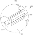
- FIG. 3 is an enlarged view showing a portion A of FIG. 2
- FIG. 4 is a perspective view showing the case and the label of the secondary battery module according to the first embodiment of the present disclosure, which are assembled
- FIG. 5 is an enlarged view showing a portion B of FIG. 4
- FIG. 6 is a cross-sectioned view of FIG. 4
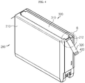
- FIG. 7 is a perspective view showing that the handle unit of FIG. 4 is bent upward
- FIG. 8 is a perspective view showing that the handle unit of FIG. 7 overlaps with the label body.
- a secondary battery module 10 includes a secondary battery cell 100, a case 200, and a label 300.
- the secondary battery cell 100 may be selected from various types of secondary battery cells.
- the secondary battery cell 100 may have a cylindrical shape, a rectangular shape, or a pouch shape.
- the secondary battery cell 100 will be mainly described as having a cylindrical shape. Even though FIG. 6 illustrates that three cylindrical secondary battery cells 100 are accommodated in the case 200, the number of secondary battery cells 100 may be changed.
- the secondary battery cell 100 includes an electrode assembly, for example a jelly-roll type electrode assembly, a cylindrical battery case accommodating an electrolyte solution together with the electrode assembly, a positive electrode terminal formed at, for example, an upper portion of the battery case, and a negative electrode terminal formed at, for example, a lower portion of the battery case.
- the electrode assembly may have a structure wound in a jelly-roll form in a state where a separator is interposed between a positive electrode and a negative electrode.
- a positive electrode lead (not shown) is attached to the positive electrode and connected to a positive electrode terminal at, for example, the upper portion of the battery case, and a negative electrode lead (not shown) is attached to the negative electrode terminal at, for example, a lower portion of the battery case.
- a cylindrical center pin (not shown) may be inserted at the center of the electrode assembly.
- the center pin (not shown) may fix and support the electrode assembly and serve as a passage for releasing gas generated by internal reactions during charge, discharge and operation.
- a safety vent (not shown) may be provided in the battery case, for example, at a lower portion of a top cap (not shown), so that the safety vent is broken by a pressure rise inside the battery case to discharge the gas.
- the plurality of secondary battery cells 100 are accommodated in the case 200 (see FIG. 6 ), and the case 200 has an insert opening 220.
- a label 300 explained later, may be inserted into the insert opening 220.
- the case 200 may include a case body 210 and an insert opening 220.
- the case body 210 and the insert opening 220 will be described.
- the plurality of secondary battery cells 100 are accommodated in the case body 210, and the case body 210 protects the secondary battery cells 100.
- the case body 210 may have various shapes corresponding to the shapes of various devices or systems at which the secondary battery module 10 is installed. Also, the case body 210 may be made of various materials with predetermined rigidity to protect the secondary battery cells 100. Referring to FIG. 2 , the case body 210 may have a placing groove 211 in which the label 300 is placed. That is, a label body 310 of the label 300, explained later, is placed in the placing groove 211 of the case body 210, and a handle unit 320 of the label 300 may be inserted into the insert opening 220.
- the insert opening 220 may be formed at both ends of an upper side of the case body 210, based on FIGS. 2 and 3 .
- the insert opening 220 may be formed over an upper side of the case body 210 and a side surface of the case body 210. That is, the insert opening 220 includes a first opening 221 and a second opening 222, and the first opening 221 is formed at the upper side of the case body 210 and the second opening 222 is formed at the side surface of the case body 210.
- the first opening 221and the second opening 222 communicate with each other.
- a dividing unit 212 is formed at the case body 210.
- the dividing unit 212 is disposed between the first opening 221 and the second opening 222 to divide the first opening 221 and the second opening 222.
- the first opening 221 may be formed at, for example, a side surface of the dividing unit 212
- the second opening 222 may be formed at, for example, a lower side of the dividing unit 212.
- the label 300 may include a label body 310 and a handle unit 320.
- the label body 310 may be coupled to the placing groove 211 formed at the case body 210, and various information regarding the secondary battery module 10 may be written on the label body 310.
- the handle unit 320 extends by a predetermined length from both ends of the label body 310 and may be inserted into the insert opening 220 through the end of the handle unit 320. Referring to FIG. 2 , the label body 310 and the handle unit 320 may be integrally fabricated, and the width d1 of the label body 310 may be larger than the width d2 of the handle unit 320.
- an end of the handle unit 320 may be firstly inserted through the first opening 221 formed at the upper side of the case body 210 and then discharged through the second opening 222 formed at the side surface of the case body 210 and communicated with the first opening 221.
- the handle unit 320 discharged through the second opening 222 communicating with the first opening 221 is lifted upward based on FIG. 7 while being supported by the dividing unit 212.
- the handle unit 320 is folded toward the label body 310 while being supported by the dividing unit 212 to overlap with the label body 310.
- a bonding member 400 may be coupled to the handle unit 320, and the handle unit 320 may be coupled to the label body 310 by the bonding member 400. That is, the bonding member 400 such as a double-sided tape is coupled to an end portion of the handle unit 320.
- the double-sided tape attaches the handle unit 320 to the label body 310.
- the handle unit 320 may be detachably fixed to the label body 310. That is, the handle unit 320 may be separated from the label body 310 by removing the double-sided tape or by applying a force over a predetermined level.
- the handle unit 320 of the label 300 provided at the secondary battery module 10 is folded while being supported by the dividing unit 212 to be attached to the label body 310 by the bonding member 400 in a state of overlapping with the label body 310.
- the secondary battery module 10 according to the first embodiment of the present disclosure may be mounted to various devices or systems in the state of FIG. 8 .
- the secondary battery module 10 of this embodiment may be mounted to an audio video navigation (AVN) system provided at a vehicle.
- the handle unit 320 is separated from the label body 310 by removing the bonding member 400 such as a double-sided tape adhered to the label body 310 to come to a state depicted in FIG.
- the secondary battery module 10 may be separated from various devices or systems. Then, a new secondary battery module 10 may be mounted to the device or system, thereby exchanging the secondary battery module 10.
- the label 300 since various information about the secondary battery module 10 is described on the label body 310 of the label 300, the label 300 may perform the function and role of a label.
- the secondary battery module 10 since the secondary battery module 10 may be separated from the device or system by the handle unit 320 of the label 300, a worker may easily exchange the secondary battery module 10.
- FIG. 9 is an exploded perspective view showing a case and a cover of a secondary battery module according to the second embodiment of the present disclosure.
- a cover 500 is coupled to the case 200, different from the first embodiment.
- the cover 500 may be coupled to the case 200 at a position where the label 300 is located in order to protect the label 300.
- the cover 500 is detachably coupled to the case 200. If the secondary battery module 10 is coupled to various devices or systems, since the cover 500 covers the label 300, the label 300 is protected from an external impact.
- the secondary battery module 10 may be separated from various devices or systems by using the handle unit 320 of the label 300 as described in the first embodiment, after the cover 500 is removed in advance.
- a vehicle (not shown) according to an embodiment of the present disclosure may include the secondary battery module 10 described above.
- the secondary battery module 10 according to each embodiment of the present disclosure may be applied to not only a vehicle using an engine but also a predetermined vehicle (not shown) using electricity like an electric vehicle or a hybrid electric vehicle.
- the present disclosure is directed to a secondary battery module and is particularly applicable to industries associated with a secondary battery.
Landscapes
- Chemical Kinetics & Catalysis (AREA)
- Electrochemistry (AREA)
- General Chemical & Material Sciences (AREA)
- Chemical & Material Sciences (AREA)
- Engineering & Computer Science (AREA)
- Sustainable Development (AREA)
- Life Sciences & Earth Sciences (AREA)
- Sustainable Energy (AREA)
- Power Engineering (AREA)
- Transportation (AREA)
- Mechanical Engineering (AREA)
- Aviation & Aerospace Engineering (AREA)
- Battery Mounting, Suspending (AREA)
Abstract
Description
- The present application claims priority to Korean Patent Application No.
10-2017-0167138 filed on December 7, 2017 - The present disclosure relates to a secondary battery module, and more particularly, to a secondary battery module that is easily exchangeable in a convenient and easy way.
- As technology development and demand for a mobile device have increased, demand for a secondary battery as an energy source has rapidly increased. Conventionally, a nickel-cadmium battery or a hydrogen ion battery has been used as the secondary battery. However, a lithium secondary battery is recently widely used because charging and discharging is free due to rare memory effect in comparison with a nickel-based secondary battery, a self-discharge rate is very low, and an energy density is high.
- The lithium secondary battery mainly uses a lithium oxide and a carbonaceous material as a positive electrode active material and a negative electrode active material, respectively. The lithium secondary battery includes a secondary battery cell in which a positive electrode plate and a negative electrode plate, respectively coated with the positive electrode active material and the negative electrode active material, are arranged with a separator therebetween, and an outer member, that is a battery case, which seals and receives the secondary battery cell together with an electrolyte solution.
- The lithium secondary battery includes a positive electrode, a negative electrode, and a separator interposed therebetween and an electrolyte. Depending on which material is used for the positive electrode active material and the negative electrode active material, the lithium secondary battery is classified into a lithium ion battery (LIB) and a polymer lithium ion battery (PLIB). Generally, an electrode of the lithium secondary battery is prepared by applying the positive or negative electrode active material to a current collector made of aluminum or copper sheet, mesh, film, foil, or the like and then drying the same.
- Generally, the secondary battery may be classified into cylindrical, rectangular and pouch-type secondary batteries depending on the shape of the exterior in which a secondary battery cell is accommodated.
-
FIG. 1 is a perspective view showing a conventional secondary battery module. - When a secondary battery module 1 is used in various devices or systems, the secondary battery module 1 may have to be exchanged since its life span expires. Referring to
FIG. 1 , a conventional secondary battery module 1 includes ahandle 4 attached to an upper side of acase 2, and alabel 3 attached to a side surface of thecase 2. A worker pulls thehandle 4 coupled to the upper side of thecase 2 to separate the secondary battery module 1 from the device or system, and then couples a new secondary battery module 1 to the device or system. Here, if thehandle 4 coupled to thecase 2 is fabricated to have a large size, the entire volume of the secondary battery module 1 is increased, and also the secondary battery module 1 is not easily installed due to the interference between the device or system and thehandle 4. If thehandle 4 is fabricated to have a small size, it is not easy for the worker to grip thehandle 4, which makes it difficult to exchange the secondary battery module 1. - The present disclosure is directed to providing a secondary battery module, which may be easily exchanged by a worker.
- The present disclosure is also directed to providing a secondary battery module, which may include a case whose entire volume is reduced.
- The present disclosure is also directed to providing a secondary battery module, which may include a label serving as a handle so that it is not needed to fabricate a handle separately.
- In one aspect of the present disclosure, there is provided a secondary battery module, comprising: a plurality of secondary battery cells; a case configured to accommodate the plurality of secondary battery cells and having an insert opening; and a label coupled to the case and inserted into the insert opening of the case.
- Also, the case may have a placing groove in which the label is placed.
- In addition, the label may include a label body coupled to the case; and handle units respectively extending from both ends of the label body by a predetermined length to be inserted into the insert opening.
- Also, the case may include a case body in which the plurality of secondary battery cells are accommodated; and insert openings formed at both ends of an upper side of the case body.
- In addition, the insert opening may be formed over an upper side of the case body and a side surface of the case body.
- Also, the insert opening may include: a first opening formed at the upper side of the case body; and a second opening formed at the side surface of the case body to communicate with the first opening, wherein the case body may include a dividing unit disposed between the first opening and the second opening to divide the first opening and the second opening.
- Also, the first opening may be formed at a side surface of the dividing unit, and the second opening may be formed at a lower side of the dividing unit.
- In addition, after being inserted into the insert opening, the handle unit may be folded to overlap with the label body.
- Also, the handle unit may be inserted through the first opening, be discharged through the second opening, and be folded while being supported by the dividing unit.
- In addition, the secondary battery module may further comprise a bonding member configured to couple the handle unit to the label body.
- Also, the secondary battery module may further comprise a cover coupled to the case at a position where the label is located in order to protect the label.
- In another aspect of the present disclosure, there is also provided a vehicle, comprising the secondary battery module described above.
- According to the embodiments of the present disclosure, since the label coupled to the case may function as a handle, a worker may simply exchange the secondary battery module while gripping the label.
- In addition, since the handle is unnecessary, the entire volume of the case may be reduced.
- Moreover, since the label may function as a handle, it is not needed to fabricate a handle separately, thereby allowing easy manufacturing with reduced costs.
-
-
FIG. 1 is a perspective view showing a conventional secondary battery module. -
FIG. 2 is an exploded perspective view showing a case and a label of a secondary battery module according to the first embodiment of the present disclosure. -
FIG. 3 is an enlarged view showing a portion A ofFIG. 2 . -
FIG. 4 is a perspective view showing the case and the label of the secondary battery module according to the first embodiment of the present disclosure, which are assembled. -
FIG. 5 is an enlarged view showing a portion B ofFIG. 4 . -
FIG. 6 is a cross-sectioned view ofFIG. 4 . -
FIG. 7 is a perspective view showing that the handle unit ofFIG. 4 is bent upward. -
FIG. 8 is a perspective view showing that the handle unit ofFIG. 7 overlaps with the label body. -
FIG. 9 is an exploded perspective view showing a case and a cover of a secondary battery module according to the second embodiment of the present disclosure. - Hereinafter, preferred embodiments of the present disclosure will be described in detail with reference to the accompanying drawings. Prior to the description, it should be understood that the terms used in the specification and the appended claims should not be construed as limited to general and dictionary meanings, but interpreted based on the meanings and concepts corresponding to technical aspects of the present disclosure on the basis of the principle that the inventor is allowed to define terms appropriately for the best explanation. Therefore, the description proposed herein is just a preferable example for the purpose of illustrations only, not intended to limit the scope of the disclosure, so it should be understood that other equivalents and modifications could be made thereto without departing from the scope of the disclosure.
- In the drawings, the size of each element or a specific part of the element may be exaggerated, omitted, or schematically illustrated for convenience and clarity of a description. Thus, the size of each element does not entirely reflect the actual size of the element. A detailed description of well-known functions or elements associated with the present disclosure will be omitted if it unnecessarily obscures the subject matter of the present disclosure.
- The term, 'combine' or 'connect' as used herein, may refer not only to a case where one member and another member are directly combined or directly connected but also a case where one member is indirectly combined with another member via a connecting member or is indirectly connected.
-
FIG. 2 is an exploded perspective view showing a case and a label of a secondary battery module according to the first embodiment of the present disclosure,FIG. 3 is an enlarged view showing a portion A ofFIG. 2 ,FIG. 4 is a perspective view showing the case and the label of the secondary battery module according to the first embodiment of the present disclosure, which are assembled,FIG. 5 is an enlarged view showing a portion B ofFIG. 4 ,FIG. 6 is a cross-sectioned view ofFIG. 4 ,FIG. 7 is a perspective view showing that the handle unit ofFIG. 4 is bent upward, andFIG. 8 is a perspective view showing that the handle unit ofFIG. 7 overlaps with the label body. - Referring to
FIGS. 2 to 8 , asecondary battery module 10 according to the first embodiment of the present disclosure includes asecondary battery cell 100, acase 200, and alabel 300. - The secondary battery cell 100 (see
FIG. 6 ) may be selected from various types of secondary battery cells. For example, thesecondary battery cell 100 may have a cylindrical shape, a rectangular shape, or a pouch shape. Hereinafter, for convenience of explanation, thesecondary battery cell 100 will be mainly described as having a cylindrical shape. Even thoughFIG. 6 illustrates that three cylindricalsecondary battery cells 100 are accommodated in thecase 200, the number ofsecondary battery cells 100 may be changed. - If the
secondary battery cell 100 has a cylindrical shape, thesecondary battery cell 100 includes an electrode assembly, for example a jelly-roll type electrode assembly, a cylindrical battery case accommodating an electrolyte solution together with the electrode assembly, a positive electrode terminal formed at, for example, an upper portion of the battery case, and a negative electrode terminal formed at, for example, a lower portion of the battery case. The electrode assembly may have a structure wound in a jelly-roll form in a state where a separator is interposed between a positive electrode and a negative electrode. A positive electrode lead (not shown) is attached to the positive electrode and connected to a positive electrode terminal at, for example, the upper portion of the battery case, and a negative electrode lead (not shown) is attached to the negative electrode terminal at, for example, a lower portion of the battery case. In addition, a cylindrical center pin (not shown) may be inserted at the center of the electrode assembly. The center pin (not shown) may fix and support the electrode assembly and serve as a passage for releasing gas generated by internal reactions during charge, discharge and operation. Meanwhile, a safety vent (not shown) may be provided in the battery case, for example, at a lower portion of a top cap (not shown), so that the safety vent is broken by a pressure rise inside the battery case to discharge the gas. - The plurality of
secondary battery cells 100 are accommodated in the case 200 (seeFIG. 6 ), and thecase 200 has aninsert opening 220. Alabel 300, explained later, may be inserted into theinsert opening 220. Thecase 200 may include acase body 210 and aninsert opening 220. Hereinafter, thecase body 210 and theinsert opening 220 will be described. - The plurality of
secondary battery cells 100 are accommodated in thecase body 210, and thecase body 210 protects thesecondary battery cells 100. Thecase body 210 may have various shapes corresponding to the shapes of various devices or systems at which thesecondary battery module 10 is installed. Also, thecase body 210 may be made of various materials with predetermined rigidity to protect thesecondary battery cells 100. Referring toFIG. 2 , thecase body 210 may have a placinggroove 211 in which thelabel 300 is placed. That is, alabel body 310 of thelabel 300, explained later, is placed in the placinggroove 211 of thecase body 210, and ahandle unit 320 of thelabel 300 may be inserted into theinsert opening 220. - Referring to
FIGS. 2 and3 , theinsert opening 220 may be formed at both ends of an upper side of thecase body 210, based onFIGS. 2 and3 . In addition, theinsert opening 220 may be formed over an upper side of thecase body 210 and a side surface of thecase body 210. That is, theinsert opening 220 includes afirst opening 221 and asecond opening 222, and thefirst opening 221 is formed at the upper side of thecase body 210 and thesecond opening 222 is formed at the side surface of thecase body 210. The first opening 221and thesecond opening 222 communicate with each other. Here, adividing unit 212 is formed at thecase body 210. The dividingunit 212 is disposed between thefirst opening 221 and thesecond opening 222 to divide thefirst opening 221 and thesecond opening 222. Referring toFIGS. 2 and3 , thefirst opening 221 may be formed at, for example, a side surface of thedividing unit 212, and thesecond opening 222 may be formed at, for example, a lower side of thedividing unit 212. - One side of the
label 300 is coupled to thecase 200, and the other side of thelabel 300 extending from one side is inserted into the insert opening 220 of thecase 200. Thelabel 300 may include alabel body 310 and ahandle unit 320. Thelabel body 310 may be coupled to the placinggroove 211 formed at thecase body 210, and various information regarding thesecondary battery module 10 may be written on thelabel body 310. Thehandle unit 320 extends by a predetermined length from both ends of thelabel body 310 and may be inserted into theinsert opening 220 through the end of thehandle unit 320. Referring toFIG. 2 , thelabel body 310 and thehandle unit 320 may be integrally fabricated, and the width d1 of thelabel body 310 may be larger than the width d2 of thehandle unit 320. - Seeing the
label 300 shown inFIGS. 4 and5 , an end of thehandle unit 320 may be firstly inserted through thefirst opening 221 formed at the upper side of thecase body 210 and then discharged through thesecond opening 222 formed at the side surface of thecase body 210 and communicated with thefirst opening 221. In addition, referring toFIG. 7 , thehandle unit 320 discharged through thesecond opening 222 communicating with thefirst opening 221 is lifted upward based onFIG. 7 while being supported by the dividingunit 212. In addition, referring toFIG. 8 , thehandle unit 320 is folded toward thelabel body 310 while being supported by the dividingunit 212 to overlap with thelabel body 310. Meanwhile, abonding member 400 may be coupled to thehandle unit 320, and thehandle unit 320 may be coupled to thelabel body 310 by thebonding member 400. That is, thebonding member 400 such as a double-sided tape is coupled to an end portion of thehandle unit 320. In this state, if thehandle unit 320 is folded to overlap with thelabel body 310, the double-sided tape attaches thehandle unit 320 to thelabel body 310. By doing so, thehandle unit 320 may be detachably fixed to thelabel body 310. That is, thehandle unit 320 may be separated from thelabel body 310 by removing the double-sided tape or by applying a force over a predetermined level. - Hereinafter, the operation and effect of the
secondary battery module 10 according to the first embodiment of the present disclosure will be described with reference to the drawings. - As in
FIG. 8 , thehandle unit 320 of thelabel 300 provided at thesecondary battery module 10 is folded while being supported by the dividingunit 212 to be attached to thelabel body 310 by thebonding member 400 in a state of overlapping with thelabel body 310. Thesecondary battery module 10 according to the first embodiment of the present disclosure may be mounted to various devices or systems in the state ofFIG. 8 . For example, thesecondary battery module 10 of this embodiment may be mounted to an audio video navigation (AVN) system provided at a vehicle. In addition, if the life span of thesecondary battery module 10 expires, thehandle unit 320 is separated from thelabel body 310 by removing thebonding member 400 such as a double-sided tape adhered to thelabel body 310 to come to a state depicted inFIG. 7 . In this state, if a worker grips and pulls twohandle units 320 depicted inFIG. 7 , thesecondary battery module 10 may be separated from various devices or systems. Then, a newsecondary battery module 10 may be mounted to the device or system, thereby exchanging thesecondary battery module 10. In other words, in thesecondary battery module 10 according to the first embodiment of the present disclosure, since various information about thesecondary battery module 10 is described on thelabel body 310 of thelabel 300, thelabel 300 may perform the function and role of a label. In addition, since thesecondary battery module 10 may be separated from the device or system by thehandle unit 320 of thelabel 300, a worker may easily exchange thesecondary battery module 10. -
FIG. 9 is an exploded perspective view showing a case and a cover of a secondary battery module according to the second embodiment of the present disclosure. - Hereinafter, the operation and effect of the
secondary battery module 10 according to the second embodiment of the present disclosure will be described with reference toFIG. 9 , and the features identical to those of thesecondary battery module 10 according to the first embodiment of the present disclosure will not be described again in detail. - In the second embodiment of the present disclosure, a
cover 500 is coupled to thecase 200, different from the first embodiment. - Referring to
FIG. 9 , thecover 500 may be coupled to thecase 200 at a position where thelabel 300 is located in order to protect thelabel 300. Here, thecover 500 is detachably coupled to thecase 200. If thesecondary battery module 10 is coupled to various devices or systems, since thecover 500 covers thelabel 300, thelabel 300 is protected from an external impact. In addition, if it is required to exchange thesecondary battery module 10, thesecondary battery module 10 may be separated from various devices or systems by using thehandle unit 320 of thelabel 300 as described in the first embodiment, after thecover 500 is removed in advance. - Meanwhile, a vehicle (not shown) according to an embodiment of the present disclosure may include the
secondary battery module 10 described above. In addition, thesecondary battery module 10 according to each embodiment of the present disclosure may be applied to not only a vehicle using an engine but also a predetermined vehicle (not shown) using electricity like an electric vehicle or a hybrid electric vehicle. - The present disclosure has been described in detail. However, it should be understood that the detailed description and specific examples, while indicating preferred embodiments of the disclosure, are given by way of illustration only, since various changes and modifications within the scope of the disclosure will become apparent to those skilled in the art from this detailed description.
- The present disclosure is directed to a secondary battery module and is particularly applicable to industries associated with a secondary battery.
Claims (12)
- A secondary battery module, comprising:a plurality of secondary battery cells;a case configured to accommodate the plurality of secondary battery cells and having an insert opening; anda label coupled to the case and inserted into the insert opening of the case.
- The secondary battery module according to claim 1,
wherein the case has a placing groove in which the label is placed. - The secondary battery module according to claim 1,
wherein the label includes:a label body coupled to the case; andhandle units respectively extending from both ends of the label body by a predetermined length to be inserted into the insert opening. - The secondary battery module according to claim 3,
wherein the case includes:a case body in which the plurality of secondary battery cells are accommodated; andinsert openings formed at both ends of an upper side of the case body. - The secondary battery module according to claim 4,
wherein the insert opening is formed over an upper side of the case body and a side surface of the case body. - The secondary battery module according to claim 5,
wherein the insert opening includes:a first opening formed at the upper side of the case body; anda second opening formed at the side surface of the case body to communicate with the first opening,wherein the case body includes a dividing unit disposed between the first opening and the second opening to divide the first opening and the second opening. - The secondary battery module according to claim 6,
wherein the first opening is formed at a side surface of the dividing unit, and the second opening is formed at a lower side of the dividing unit. - The secondary battery module according to claim 6,
wherein after being inserted into the insert opening, the handle unit is folded to overlap with the label body. - The secondary battery module according to claim 8,
wherein the handle unit is inserted through the first opening, is discharged through the second opening, and is folded while being supported by the dividing unit. - The secondary battery module according to claim 8, further comprising:
a bonding member configured to couple the handle unit to the label body. - The secondary battery module according to claim 8, further comprising:
a cover coupled to the case at a position where the label is located in order to protect the label. - A vehicle, comprising a secondary battery module according to any one of claims 1 to 11.
Applications Claiming Priority (2)
| Application Number | Priority Date | Filing Date | Title |
|---|---|---|---|
| KR1020170167138A KR102248230B1 (en) | 2017-12-07 | 2017-12-07 | Secondary battery module |
| PCT/KR2018/013486 WO2019112191A1 (en) | 2017-12-07 | 2018-11-07 | Secondary battery module |
Publications (3)
| Publication Number | Publication Date |
|---|---|
| EP3637496A1 true EP3637496A1 (en) | 2020-04-15 |
| EP3637496A4 EP3637496A4 (en) | 2020-08-19 |
| EP3637496B1 EP3637496B1 (en) | 2023-12-27 |
Family
ID=66751063
Family Applications (1)
| Application Number | Title | Priority Date | Filing Date |
|---|---|---|---|
| EP18884910.3A Active EP3637496B1 (en) | 2017-12-07 | 2018-11-07 | Secondary battery module |
Country Status (8)
| Country | Link |
|---|---|
| US (1) | US11251498B2 (en) |
| EP (1) | EP3637496B1 (en) |
| JP (1) | JP7037010B2 (en) |
| KR (1) | KR102248230B1 (en) |
| CN (1) | CN110612618B (en) |
| ES (1) | ES2970686T3 (en) |
| HU (1) | HUE065131T2 (en) |
| WO (1) | WO2019112191A1 (en) |
Families Citing this family (2)
| Publication number | Priority date | Publication date | Assignee | Title |
|---|---|---|---|---|
| KR102684808B1 (en) | 2020-03-25 | 2024-07-11 | 주식회사 엘지에너지솔루션 | Battery Pack with a handle which has a loose stopper |
| CN113844283A (en) * | 2020-06-28 | 2021-12-28 | 陕西帝亚新能源汽车有限公司 | Battery pack structure for new energy automobile |
Family Cites Families (41)
| Publication number | Priority date | Publication date | Assignee | Title |
|---|---|---|---|---|
| JPS57148771U (en) | 1981-03-13 | 1982-09-18 | ||
| JPS58187964U (en) | 1982-06-09 | 1983-12-14 | 横河電機株式会社 | battery extractor |
| IT1239843B (en) * | 1990-03-06 | 1993-11-15 | Olimpio Stocchiero | LID WITH HANDLE FOR ACCUMULATOR CONTAINERS |
| DE69131064T2 (en) | 1990-06-12 | 1999-11-18 | Hitachi Maxell, Ltd. | ORGANIC, ELECTROLYTIC BATTERY |
| JPH04101357U (en) | 1991-02-20 | 1992-09-01 | 三洋電機株式会社 | portable power supply |
| JPH0638154U (en) | 1992-10-21 | 1994-05-20 | 三洋電機株式会社 | Battery pack |
| IT1270552B (en) * | 1993-06-09 | 1997-05-06 | Olimpio Stocchiero | QUICK-CHARGE ACCUMULATOR CONTAINER WITH ELECTROLYTE DISTRIBUTION CHANNELS PRINTED ON THE COVER |
| JPH10223193A (en) * | 1997-02-07 | 1998-08-21 | Miyagawa Kasei Ind Co Ltd | Battery handle mounting structure |
| JPH10289701A (en) | 1997-04-15 | 1998-10-27 | Matsushita Electric Ind Co Ltd | Lead-acid battery |
| US6022638A (en) * | 1997-05-20 | 2000-02-08 | Gnb Technologies, Inc. | Lead-acid battery with handle |
| US6224998B1 (en) | 1999-02-04 | 2001-05-01 | Delphi Technologies, Inc. | Battery, tray and heat shield assembly |
| KR200187069Y1 (en) * | 1999-12-06 | 2000-06-15 | 강성천 | Label attached to the body of dry cell |
| KR100408633B1 (en) | 2001-06-19 | 2003-12-06 | 주식회사 델코 | Battery |
| JP4123515B2 (en) * | 2003-12-26 | 2008-07-23 | ソニー株式会社 | Battery device |
| JP4696674B2 (en) | 2005-05-11 | 2011-06-08 | 株式会社Gsユアサ | Packaging box and battery packed in this packaging box |
| KR100892047B1 (en) | 2006-09-18 | 2009-04-07 | 주식회사 엘지화학 | Battery Modules and Medium and Large Battery Packs |
| TWM314136U (en) * | 2007-01-08 | 2007-06-21 | Wus Tech Co Ltd | Improved structure for positioning battery of powered wheelchair |
| JP2008171726A (en) | 2007-01-12 | 2008-07-24 | Sanyo Electric Co Ltd | Battery pack |
| KR100864887B1 (en) * | 2007-05-25 | 2008-10-22 | 삼성에스디아이 주식회사 | Secondary battery |
| KR100878285B1 (en) | 2007-06-05 | 2009-01-12 | 삼성에스디아이 주식회사 | Battery pack |
| JP2009158182A (en) * | 2007-12-25 | 2009-07-16 | Sanyo Electric Co Ltd | Battery pack |
| US20110223447A1 (en) | 2010-03-15 | 2011-09-15 | Research In Motion Limited | Power pack removal device for a portable electronic device |
| KR200468292Y1 (en) | 2011-06-02 | 2013-08-05 | 장을호 | Structure for jacket label of battery |
| CN102364718A (en) * | 2011-11-02 | 2012-02-29 | 无锡东南车辆科技有限公司 | Handle structure for battery box cover |
| US8579425B2 (en) | 2012-01-27 | 2013-11-12 | Eastman Kodak Company | Seal and secondary film for ink tank |
| KR101908452B1 (en) | 2012-06-28 | 2018-10-17 | 에스케이이노베이션 주식회사 | Easy assembling all-in-one secondary battery module |
| JP2014022129A (en) | 2012-07-17 | 2014-02-03 | Shin Kobe Electric Mach Co Ltd | Lithium ion battery |
| US9287536B2 (en) * | 2012-08-07 | 2016-03-15 | John E. Waters | Battery module construction |
| US20150325818A1 (en) | 2012-08-27 | 2015-11-12 | Nec Energy Devices, Ltd. | Power storage device |
| KR101364096B1 (en) * | 2013-02-01 | 2014-02-20 | 삼성에스디아이 주식회사 | Battery pack assembly |
| KR101430621B1 (en) * | 2013-02-05 | 2014-08-14 | 삼성에스디아이 주식회사 | Battery Pack |
| KR200475243Y1 (en) | 2013-09-11 | 2014-11-20 | 김종석 | Goods hanger device |
| KR101520391B1 (en) | 2014-02-11 | 2015-05-14 | 삼성에스디아이 주식회사 | Battery Pack |
| KR101466804B1 (en) | 2014-02-25 | 2014-12-01 | 이학선 | The multi-bag free to change the belt |
| JP6300626B2 (en) | 2014-04-30 | 2018-03-28 | シャープ株式会社 | Portable device |
| DE102014009952A1 (en) | 2014-07-07 | 2016-01-07 | Focke & Co. (Gmbh & Co. Kg) | Pack, in particular cigarette pack |
| US20160197323A1 (en) * | 2015-01-05 | 2016-07-07 | Johnson Controls Technology Company | Battery module vent and handle configuration system and method |
| KR101844113B1 (en) | 2015-03-05 | 2018-05-14 | 주식회사 엘지화학 | Battery Pack |
| CN205159387U (en) * | 2015-10-30 | 2016-04-13 | 松下能源(无锡)有限公司 | Battery case and used battery package of this battery case |
| KR102021110B1 (en) | 2016-01-08 | 2019-09-11 | 주식회사 엘지화학 | Battery pack |
| KR20170044070A (en) * | 2017-04-07 | 2017-04-24 | 주식회사 엘지화학 | Battery Provided with Extension for Pulling |
-
2017
- 2017-12-07 KR KR1020170167138A patent/KR102248230B1/en active Active
-
2018
- 2018-11-07 EP EP18884910.3A patent/EP3637496B1/en active Active
- 2018-11-07 US US16/611,160 patent/US11251498B2/en active Active
- 2018-11-07 HU HUE18884910A patent/HUE065131T2/en unknown
- 2018-11-07 WO PCT/KR2018/013486 patent/WO2019112191A1/en not_active Ceased
- 2018-11-07 ES ES18884910T patent/ES2970686T3/en active Active
- 2018-11-07 CN CN201880029403.5A patent/CN110612618B/en active Active
- 2018-11-07 JP JP2019559027A patent/JP7037010B2/en active Active
Also Published As
| Publication number | Publication date |
|---|---|
| EP3637496B1 (en) | 2023-12-27 |
| US11251498B2 (en) | 2022-02-15 |
| KR102248230B1 (en) | 2021-05-03 |
| US20200083503A1 (en) | 2020-03-12 |
| KR20190067325A (en) | 2019-06-17 |
| JP7037010B2 (en) | 2022-03-16 |
| JP2020518955A (en) | 2020-06-25 |
| CN110612618B (en) | 2022-04-26 |
| HUE065131T2 (en) | 2024-05-28 |
| WO2019112191A1 (en) | 2019-06-13 |
| CN110612618A (en) | 2019-12-24 |
| EP3637496A4 (en) | 2020-08-19 |
| ES2970686T3 (en) | 2024-05-30 |
Similar Documents
| Publication | Publication Date | Title |
|---|---|---|
| EP3624214B1 (en) | Cylindrical secondary battery module and method for producing cylindrical secondary battery module | |
| EP3467903B1 (en) | Battery pack | |
| EP3550635B1 (en) | Battery module and battery pack including the same | |
| EP3297061B1 (en) | Battery pack | |
| EP3739666B1 (en) | Pouch-type battery cell comprising venting member and battery pack comprising the same | |
| EP3686986B1 (en) | Battery module and battery pack including the same | |
| EP3573130A1 (en) | Battery pack | |
| US10658631B2 (en) | Secondary battery | |
| EP4726864A1 (en) | Battery cell, battery, and electrical device | |
| CN215896616U (en) | Electrode assembly, battery monomer, battery and consumer | |
| EP3261152A1 (en) | Battery module, battery pack including same, and method for manufacturing casing for battery module | |
| JP7594107B2 (en) | Electrode assembly, battery cell, battery and power consuming device | |
| KR20160144325A (en) | Electrode lead and secondary battery including the same | |
| EP3675235A1 (en) | Cylindrical secondary battery module | |
| EP3637496B1 (en) | Secondary battery module | |
| EP4102607A1 (en) | Electrode assembly, battery cell, battery, and method and device for manufacturing electrode assembly | |
| EP3671892B1 (en) | Battery pack and label attaching method thereof | |
| JP7542624B2 (en) | Battery packs, electronic devices, and automobiles | |
| EP3989334A1 (en) | Battery module, and battery pack and vehicle comprising same | |
| EP4432446B1 (en) | Battery module, and battery pack and vehicle including the same | |
| KR20190069044A (en) | Battery module and battery pack including the same | |
| CN220710582U (en) | Acquisition device, battery and power utilization device | |
| CN221262602U (en) | Battery module, battery and electricity utilization device | |
| EP4564547A1 (en) | Battery cell and battery module including the same | |
| EP4184688B1 (en) | Exhaust device, battery cell, battery and electric device |
Legal Events
| Date | Code | Title | Description |
|---|---|---|---|
| STAA | Information on the status of an ep patent application or granted ep patent |
Free format text: STATUS: THE INTERNATIONAL PUBLICATION HAS BEEN MADE |
|
| PUAI | Public reference made under article 153(3) epc to a published international application that has entered the european phase |
Free format text: ORIGINAL CODE: 0009012 |
|
| STAA | Information on the status of an ep patent application or granted ep patent |
Free format text: STATUS: REQUEST FOR EXAMINATION WAS MADE |
|
| 17P | Request for examination filed |
Effective date: 20200107 |
|
| AK | Designated contracting states |
Kind code of ref document: A1 Designated state(s): AL AT BE BG CH CY CZ DE DK EE ES FI FR GB GR HR HU IE IS IT LI LT LU LV MC MK MT NL NO PL PT RO RS SE SI SK SM TR |
|
| AX | Request for extension of the european patent |
Extension state: BA ME |
|
| A4 | Supplementary search report drawn up and despatched |
Effective date: 20200721 |
|
| RIC1 | Information provided on ipc code assigned before grant |
Ipc: H01M 2/10 20060101AFI20200715BHEP Ipc: B60L 50/64 20190101ALI20200715BHEP |
|
| DAV | Request for validation of the european patent (deleted) | ||
| DAX | Request for extension of the european patent (deleted) | ||
| RAP1 | Party data changed (applicant data changed or rights of an application transferred) |
Owner name: LG ENERGY SOLUTION LTD. |
|
| RAP3 | Party data changed (applicant data changed or rights of an application transferred) |
Owner name: LG ENERGY SOLUTION, LTD. |
|
| REG | Reference to a national code |
Ref country code: DE Ref legal event code: R079 Free format text: PREVIOUS MAIN CLASS: H01M0002100000 Ipc: H01M0050209000 Ref document number: 602018063420 Country of ref document: DE |
|
| GRAP | Despatch of communication of intention to grant a patent |
Free format text: ORIGINAL CODE: EPIDOSNIGR1 |
|
| STAA | Information on the status of an ep patent application or granted ep patent |
Free format text: STATUS: GRANT OF PATENT IS INTENDED |
|
| RIC1 | Information provided on ipc code assigned before grant |
Ipc: B60L 50/64 20190101ALI20230510BHEP Ipc: H01M 50/213 20210101ALI20230510BHEP Ipc: H01M 50/211 20210101ALI20230510BHEP Ipc: H01M 50/209 20210101AFI20230510BHEP |
|
| INTG | Intention to grant announced |
Effective date: 20230613 |
|
| P01 | Opt-out of the competence of the unified patent court (upc) registered |
Effective date: 20230706 |
|
| GRAS | Grant fee paid |
Free format text: ORIGINAL CODE: EPIDOSNIGR3 |
|
| GRAA | (expected) grant |
Free format text: ORIGINAL CODE: 0009210 |
|
| STAA | Information on the status of an ep patent application or granted ep patent |
Free format text: STATUS: THE PATENT HAS BEEN GRANTED |
|
| AK | Designated contracting states |
Kind code of ref document: B1 Designated state(s): AL AT BE BG CH CY CZ DE DK EE ES FI FR GB GR HR HU IE IS IT LI LT LU LV MC MK MT NL NO PL PT RO RS SE SI SK SM TR |
|
| REG | Reference to a national code |
Ref country code: GB Ref legal event code: FG4D |
|
| REG | Reference to a national code |
Ref country code: CH Ref legal event code: EP |
|
| REG | Reference to a national code |
Ref country code: DE Ref legal event code: R096 Ref document number: 602018063420 Country of ref document: DE |
|
| REG | Reference to a national code |
Ref country code: IE Ref legal event code: FG4D |
|
| PG25 | Lapsed in a contracting state [announced via postgrant information from national office to epo] |
Ref country code: GR Free format text: LAPSE BECAUSE OF FAILURE TO SUBMIT A TRANSLATION OF THE DESCRIPTION OR TO PAY THE FEE WITHIN THE PRESCRIBED TIME-LIMIT Effective date: 20240328 |
|
| REG | Reference to a national code |
Ref country code: LT Ref legal event code: MG9D |
|
| PG25 | Lapsed in a contracting state [announced via postgrant information from national office to epo] |
Ref country code: LT Free format text: LAPSE BECAUSE OF FAILURE TO SUBMIT A TRANSLATION OF THE DESCRIPTION OR TO PAY THE FEE WITHIN THE PRESCRIBED TIME-LIMIT Effective date: 20231227 |
|
| PG25 | Lapsed in a contracting state [announced via postgrant information from national office to epo] |
Ref country code: LT Free format text: LAPSE BECAUSE OF FAILURE TO SUBMIT A TRANSLATION OF THE DESCRIPTION OR TO PAY THE FEE WITHIN THE PRESCRIBED TIME-LIMIT Effective date: 20231227 Ref country code: GR Free format text: LAPSE BECAUSE OF FAILURE TO SUBMIT A TRANSLATION OF THE DESCRIPTION OR TO PAY THE FEE WITHIN THE PRESCRIBED TIME-LIMIT Effective date: 20240328 Ref country code: FI Free format text: LAPSE BECAUSE OF FAILURE TO SUBMIT A TRANSLATION OF THE DESCRIPTION OR TO PAY THE FEE WITHIN THE PRESCRIBED TIME-LIMIT Effective date: 20231227 Ref country code: BG Free format text: LAPSE BECAUSE OF FAILURE TO SUBMIT A TRANSLATION OF THE DESCRIPTION OR TO PAY THE FEE WITHIN THE PRESCRIBED TIME-LIMIT Effective date: 20240327 |
|
| REG | Reference to a national code |
Ref country code: NL Ref legal event code: MP Effective date: 20231227 |
|
| REG | Reference to a national code |
Ref country code: AT Ref legal event code: MK05 Ref document number: 1645395 Country of ref document: AT Kind code of ref document: T Effective date: 20231227 |
|
| PG25 | Lapsed in a contracting state [announced via postgrant information from national office to epo] |
Ref country code: NL Free format text: LAPSE BECAUSE OF FAILURE TO SUBMIT A TRANSLATION OF THE DESCRIPTION OR TO PAY THE FEE WITHIN THE PRESCRIBED TIME-LIMIT Effective date: 20231227 |
|
| REG | Reference to a national code |
Ref country code: HU Ref legal event code: AG4A Ref document number: E065131 Country of ref document: HU |
|
| REG | Reference to a national code |
Ref country code: ES Ref legal event code: FG2A Ref document number: 2970686 Country of ref document: ES Kind code of ref document: T3 Effective date: 20240530 |
|
| PG25 | Lapsed in a contracting state [announced via postgrant information from national office to epo] |
Ref country code: SE Free format text: LAPSE BECAUSE OF FAILURE TO SUBMIT A TRANSLATION OF THE DESCRIPTION OR TO PAY THE FEE WITHIN THE PRESCRIBED TIME-LIMIT Effective date: 20231227 Ref country code: RS Free format text: LAPSE BECAUSE OF FAILURE TO SUBMIT A TRANSLATION OF THE DESCRIPTION OR TO PAY THE FEE WITHIN THE PRESCRIBED TIME-LIMIT Effective date: 20231227 Ref country code: NO Free format text: LAPSE BECAUSE OF FAILURE TO SUBMIT A TRANSLATION OF THE DESCRIPTION OR TO PAY THE FEE WITHIN THE PRESCRIBED TIME-LIMIT Effective date: 20240327 Ref country code: NL Free format text: LAPSE BECAUSE OF FAILURE TO SUBMIT A TRANSLATION OF THE DESCRIPTION OR TO PAY THE FEE WITHIN THE PRESCRIBED TIME-LIMIT Effective date: 20231227 Ref country code: LV Free format text: LAPSE BECAUSE OF FAILURE TO SUBMIT A TRANSLATION OF THE DESCRIPTION OR TO PAY THE FEE WITHIN THE PRESCRIBED TIME-LIMIT Effective date: 20231227 Ref country code: HR Free format text: LAPSE BECAUSE OF FAILURE TO SUBMIT A TRANSLATION OF THE DESCRIPTION OR TO PAY THE FEE WITHIN THE PRESCRIBED TIME-LIMIT Effective date: 20231227 |
|
| PG25 | Lapsed in a contracting state [announced via postgrant information from national office to epo] |
Ref country code: IS Free format text: LAPSE BECAUSE OF FAILURE TO SUBMIT A TRANSLATION OF THE DESCRIPTION OR TO PAY THE FEE WITHIN THE PRESCRIBED TIME-LIMIT Effective date: 20240427 |
|
| PG25 | Lapsed in a contracting state [announced via postgrant information from national office to epo] |
Ref country code: AT Free format text: LAPSE BECAUSE OF FAILURE TO SUBMIT A TRANSLATION OF THE DESCRIPTION OR TO PAY THE FEE WITHIN THE PRESCRIBED TIME-LIMIT Effective date: 20231227 Ref country code: CZ Free format text: LAPSE BECAUSE OF FAILURE TO SUBMIT A TRANSLATION OF THE DESCRIPTION OR TO PAY THE FEE WITHIN THE PRESCRIBED TIME-LIMIT Effective date: 20231227 |
|
| PG25 | Lapsed in a contracting state [announced via postgrant information from national office to epo] |
Ref country code: SK Free format text: LAPSE BECAUSE OF FAILURE TO SUBMIT A TRANSLATION OF THE DESCRIPTION OR TO PAY THE FEE WITHIN THE PRESCRIBED TIME-LIMIT Effective date: 20231227 |
|
| PG25 | Lapsed in a contracting state [announced via postgrant information from national office to epo] |
Ref country code: SM Free format text: LAPSE BECAUSE OF FAILURE TO SUBMIT A TRANSLATION OF THE DESCRIPTION OR TO PAY THE FEE WITHIN THE PRESCRIBED TIME-LIMIT Effective date: 20231227 Ref country code: SK Free format text: LAPSE BECAUSE OF FAILURE TO SUBMIT A TRANSLATION OF THE DESCRIPTION OR TO PAY THE FEE WITHIN THE PRESCRIBED TIME-LIMIT Effective date: 20231227 Ref country code: RO Free format text: LAPSE BECAUSE OF FAILURE TO SUBMIT A TRANSLATION OF THE DESCRIPTION OR TO PAY THE FEE WITHIN THE PRESCRIBED TIME-LIMIT Effective date: 20231227 Ref country code: IT Free format text: LAPSE BECAUSE OF FAILURE TO SUBMIT A TRANSLATION OF THE DESCRIPTION OR TO PAY THE FEE WITHIN THE PRESCRIBED TIME-LIMIT Effective date: 20231227 Ref country code: IS Free format text: LAPSE BECAUSE OF FAILURE TO SUBMIT A TRANSLATION OF THE DESCRIPTION OR TO PAY THE FEE WITHIN THE PRESCRIBED TIME-LIMIT Effective date: 20240427 Ref country code: EE Free format text: LAPSE BECAUSE OF FAILURE TO SUBMIT A TRANSLATION OF THE DESCRIPTION OR TO PAY THE FEE WITHIN THE PRESCRIBED TIME-LIMIT Effective date: 20231227 Ref country code: CZ Free format text: LAPSE BECAUSE OF FAILURE TO SUBMIT A TRANSLATION OF THE DESCRIPTION OR TO PAY THE FEE WITHIN THE PRESCRIBED TIME-LIMIT Effective date: 20231227 Ref country code: AT Free format text: LAPSE BECAUSE OF FAILURE TO SUBMIT A TRANSLATION OF THE DESCRIPTION OR TO PAY THE FEE WITHIN THE PRESCRIBED TIME-LIMIT Effective date: 20231227 |
|
| PG25 | Lapsed in a contracting state [announced via postgrant information from national office to epo] |
Ref country code: PL Free format text: LAPSE BECAUSE OF FAILURE TO SUBMIT A TRANSLATION OF THE DESCRIPTION OR TO PAY THE FEE WITHIN THE PRESCRIBED TIME-LIMIT Effective date: 20231227 Ref country code: PT Free format text: LAPSE BECAUSE OF FAILURE TO SUBMIT A TRANSLATION OF THE DESCRIPTION OR TO PAY THE FEE WITHIN THE PRESCRIBED TIME-LIMIT Effective date: 20240429 |
|
| PG25 | Lapsed in a contracting state [announced via postgrant information from national office to epo] |
Ref country code: PT Free format text: LAPSE BECAUSE OF FAILURE TO SUBMIT A TRANSLATION OF THE DESCRIPTION OR TO PAY THE FEE WITHIN THE PRESCRIBED TIME-LIMIT Effective date: 20240429 Ref country code: PL Free format text: LAPSE BECAUSE OF FAILURE TO SUBMIT A TRANSLATION OF THE DESCRIPTION OR TO PAY THE FEE WITHIN THE PRESCRIBED TIME-LIMIT Effective date: 20231227 |
|
| REG | Reference to a national code |
Ref country code: DE Ref legal event code: R097 Ref document number: 602018063420 Country of ref document: DE |
|
| PG25 | Lapsed in a contracting state [announced via postgrant information from national office to epo] |
Ref country code: DK Free format text: LAPSE BECAUSE OF FAILURE TO SUBMIT A TRANSLATION OF THE DESCRIPTION OR TO PAY THE FEE WITHIN THE PRESCRIBED TIME-LIMIT Effective date: 20231227 |
|
| PG25 | Lapsed in a contracting state [announced via postgrant information from national office to epo] |
Ref country code: DK Free format text: LAPSE BECAUSE OF FAILURE TO SUBMIT A TRANSLATION OF THE DESCRIPTION OR TO PAY THE FEE WITHIN THE PRESCRIBED TIME-LIMIT Effective date: 20231227 |
|
| PLBE | No opposition filed within time limit |
Free format text: ORIGINAL CODE: 0009261 |
|
| STAA | Information on the status of an ep patent application or granted ep patent |
Free format text: STATUS: NO OPPOSITION FILED WITHIN TIME LIMIT |
|
| 26N | No opposition filed |
Effective date: 20240930 |
|
| PG25 | Lapsed in a contracting state [announced via postgrant information from national office to epo] |
Ref country code: SI Free format text: LAPSE BECAUSE OF FAILURE TO SUBMIT A TRANSLATION OF THE DESCRIPTION OR TO PAY THE FEE WITHIN THE PRESCRIBED TIME-LIMIT Effective date: 20231227 |
|
| REG | Reference to a national code |
Ref country code: CH Ref legal event code: PL |
|
| PG25 | Lapsed in a contracting state [announced via postgrant information from national office to epo] |
Ref country code: MC Free format text: LAPSE BECAUSE OF FAILURE TO SUBMIT A TRANSLATION OF THE DESCRIPTION OR TO PAY THE FEE WITHIN THE PRESCRIBED TIME-LIMIT Effective date: 20231227 |
|
| PG25 | Lapsed in a contracting state [announced via postgrant information from national office to epo] |
Ref country code: LU Free format text: LAPSE BECAUSE OF NON-PAYMENT OF DUE FEES Effective date: 20241107 |
|
| REG | Reference to a national code |
Ref country code: CH Ref legal event code: PL |
|
| PG25 | Lapsed in a contracting state [announced via postgrant information from national office to epo] |
Ref country code: CH Free format text: LAPSE BECAUSE OF NON-PAYMENT OF DUE FEES Effective date: 20241130 |
|
| PG25 | Lapsed in a contracting state [announced via postgrant information from national office to epo] |
Ref country code: IE Free format text: LAPSE BECAUSE OF NON-PAYMENT OF DUE FEES Effective date: 20241107 |
|
| PGFP | Annual fee paid to national office [announced via postgrant information from national office to epo] |
Ref country code: HU Payment date: 20251127 Year of fee payment: 8 |
|
| PGFP | Annual fee paid to national office [announced via postgrant information from national office to epo] |
Ref country code: DE Payment date: 20251020 Year of fee payment: 8 |
|
| PGFP | Annual fee paid to national office [announced via postgrant information from national office to epo] |
Ref country code: GB Payment date: 20251023 Year of fee payment: 8 |
|
| PGFP | Annual fee paid to national office [announced via postgrant information from national office to epo] |
Ref country code: FR Payment date: 20251021 Year of fee payment: 8 |
|
| PGFP | Annual fee paid to national office [announced via postgrant information from national office to epo] |
Ref country code: BE Payment date: 20251020 Year of fee payment: 8 |
|
| PGFP | Annual fee paid to national office [announced via postgrant information from national office to epo] |
Ref country code: ES Payment date: 20251215 Year of fee payment: 8 |
|
| PG25 | Lapsed in a contracting state [announced via postgrant information from national office to epo] |
Ref country code: CY Free format text: LAPSE BECAUSE OF FAILURE TO SUBMIT A TRANSLATION OF THE DESCRIPTION OR TO PAY THE FEE WITHIN THE PRESCRIBED TIME-LIMIT; INVALID AB INITIO Effective date: 20181107 |