EP3637451A1 - Fuse device with micro-powered switch - Google Patents
Fuse device with micro-powered switch Download PDFInfo
- Publication number
- EP3637451A1 EP3637451A1 EP17912378.1A EP17912378A EP3637451A1 EP 3637451 A1 EP3637451 A1 EP 3637451A1 EP 17912378 A EP17912378 A EP 17912378A EP 3637451 A1 EP3637451 A1 EP 3637451A1
- Authority
- EP
- European Patent Office
- Prior art keywords
- fuse
- microswitch
- strike pin
- piece
- main shaft
- Prior art date
- Legal status (The legal status is an assumption and is not a legal conclusion. Google has not performed a legal analysis and makes no representation as to the accuracy of the status listed.)
- Granted
Links
Images




Classifications
-
- H—ELECTRICITY
- H01—ELECTRIC ELEMENTS
- H01H—ELECTRIC SWITCHES; RELAYS; SELECTORS; EMERGENCY PROTECTIVE DEVICES
- H01H85/00—Protective devices in which the current flows through a part of fusible material and this current is interrupted by displacement of the fusible material when this current becomes excessive
- H01H85/02—Details
- H01H85/30—Means for indicating condition of fuse structurally associated with the fuse
- H01H85/303—Movable indicating elements
- H01H85/306—Movable indicating elements acting on an auxiliary switch or contact
-
- H—ELECTRICITY
- H01—ELECTRIC ELEMENTS
- H01H—ELECTRIC SWITCHES; RELAYS; SELECTORS; EMERGENCY PROTECTIVE DEVICES
- H01H9/00—Details of switching devices, not covered by groups H01H1/00 - H01H7/00
- H01H9/10—Adaptation for built-in fuses
- H01H9/104—Adaptation for built-in fuses with interlocking mechanism between switch and fuse
Definitions
- the present disclosure generally relates to a technical field of electric power product, and specifically to the technical field of high voltage switching device.
- the present disclosure relates to the technical field of a fuse device, a fuse wire mounting interlocking device, and a transmission system of the fuse wire fused by a strike pin.
- a switching device In an electric power system, a switching device is used to control an ON/OFF operation of a protected element.
- three-phase fuse wires are configured as a short-circuit protection device.
- a closing operation of the switching device would not be allowed, and thereby a fuse wire mounting interlocking mechanism is needed to perform this function.
- the opening operation is performed for the fault current based on the characteristics of the fuse wires themselves.
- the other two or one phase of fuse wires are still conductive, resulting in phase-loss operation which may cause various damages to a user's device. Therefore, there is still a need for an interlocking device for fusing fuse wires, to trigger the switching device to complete the opening operation.
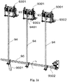
- Figs. 1A-1B illustrate a brief structural diagram of the traditional fuse wire mounting interlocking and fusing device, wherein Fig. 1A is a front stereoscope view, and Fig. 1B is a rear stereoscopic view.
- the state as shown is a state without mounting three phases of fuse wires.
- the fuse wire mounting interlocking device 93 is coupled to the three-phase fusing linkage 94.
- the fuse wire mounting piece 9301 is lifted up by the tension spring 9302, to simultaneously move the three-phase fusing linkage 94 upwardly and then overcome the resistance of the return leaf spring 9501 to rotate the rotation shaft 95 along a direction as shown by the arrow in Fig. 1A .
- the bushing 9502 on the shaft 95 is rotated to switch on the microswitch, such that the switching device performs an OPEN operation.
- the strike pin of the fuse wire When at least one phase of fuse is fused by the short-circuit current, the strike pin of the fuse wire will be triggered to be ejected out and will directly act on the crank 9303 to lift the crank 9303 up. Since the pin 9401 of the three-phase fusing linkage 94 is lap-connected to the crank 9303, the three-phase fusing linkage 94 is lifted up to rotate the rotation shaft 95 in the direction as shown by the arrow in Fig. 1 by overcoming the retention force of the return leaf spring 9501. The bushing 9502 sleeved on the rotation shaft 95 rotates along with the rotation shaft 95 to switch on the microswitch, causing the switching device OPEN and thus protecting the electric power system.
- the aforementioned fuse device incurs a complicated structure and high costs; and the complicated structure brings about labor-intensive mounting and long time for mounting.
- the present disclosure provides a fuse device with a microswitch, comprising: a microswitch, a fuse device interlocking mechanism, a fuse wire strike pin component, and a linkage, wherein the fuse wire strike pin component comprises a main shaft, a strike pin piece and a trigger piece; wherein the strike pin piece and the trigger piece are radially fixed on the main shaft, and axially movable along the main shaft; and when one or more fuse wires are not mounted, or one or more fuse wires have been fused, the fuse device interlocking mechanism cooperates with the fuse wire strike pin component, to drive the linkage to trigger the microswitch, causing the switching device not to close.
- the fuse device interlocking mechanism comprises a mounting bracket, an interlocking plate and a tension spring; and when a fuse is mounted, the interlocking plate moves in a direction in which the tension spring is extended under an action of the fuse.
- the interlocking plate comprises at least one slide rail and at least one projection for mounting the fuse.
- the fuse wire strike pin component further comprises a fuse state indicator fixed on the main shaft.
- one end of the linkage is coupled to the trigger piece, and the linkage moves vertically with a rotation of the trigger piece driven by the main shaft.
- the fuse device with the microswitch further comprises a return spring which acts on the linkage and keeps the linkage in contact with the trigger piece.
- the strike pin piece when at least one phase of fuse wires are not mounted, the strike pin piece is pushed away under an action of the interlocking plate, causing the main shaft to rotate together and simultaneously causing the trigger piece mounted thereon to rotate in a same direction, such that a link-motion of the linkage driven by the trigger piece triggers the microswitch, causing the switching device not to close.
- the link-motion of the linkage compresses the return spring.
- the strike pin piece is provided thereon with at least one protrusion which cooperates with the slide rail; when at least one phase of fuse wires are not mounted, the interlocking plate is at a position where the tension spring is reset under an action of the tension spring; when all fuse wires are mounted, the interlocking plate moves in a direction in which the tension spring is extended, and the strike pin piece drives the protrusion to rotate along the guide rail in a direction away from the main shaft under an action of the return spring.
- the interlocking plate moves in a direction in which the tension spring is reset, and the strike pin piece rotates in a direction approaching the main shaft with a movement of the protrusion along the guide rail, further causing the linkage to move.
- a strike pin of the fuse wire is ejected out and acts on the strike pin piece, causing the strike pin piece to rotate in a direction away from the fuse wire while driving the main shaft and the trigger piece to rotate in a same direction.
- the interlocking plate is mounted thereon with a fuse wire mounting indicator indicating whether a fuse wire is mounted.
- the strike pin piece and the trigger piece are coupled via a convex structure and a concave structure.
- the fuse wire mounting interlock and the strike pin system device have a simpler structure, effectively reducing production costs, and may save assembling time by the modularized assembly.
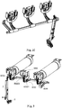
- Figs. 2A-2C are structural diagrams of an optimum embodiment of a fuse device with a microswitch of the present disclosure, wherein Fig. 2A is a schematic diagram of a stereoscope structure, Fig. 2B is a top view, and Fig. 2C is an axonometric view.
- the fuse device with a microswitch comprises a fuse device interlocking mechanism 5, a fuse wire strike pin component 6, a linkage 7 and a microswitch 2.
- the fuse device interlocking mechanism 5 cooperates with the fuse wire strike pin component 6, to drive the linkage 7 to trigger the microswitch 2, thus causing the switching device not to close.
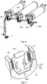
- Fig. 5 illustrates a structural diagram of a fuse device interlocking mechanism 5 of a fuse device with a microswitch according to the optimum embodiment of the present disclosure.
- the fuse device interlocking mechanism 5 comprises a mounting bracket 501, an interlocking plate 502, and a tension spring 503.
- the interlocking plate 502 is provided thereon with a first projection 5021 for mounting a British Standard (BS) fuse, and a second projection 5022 for mounting a German Standard (DIN) fuse.
- BS or DIN fuse Once the BS or DIN fuse is mounted, the interlocking plate 502 moves a certain distance toward a direction in which the tension spring is extended, i.e., the downward direction as shown in Figs. 2A-2C and Fig. 5 , under an action of the fuse.
- the interlocking plate 502 has at least one slide rail 5023. As shown, the slide rail 5023 is inclined, and the slide rail 5023 becomes closer to the fuse wires in a direction in which the tension spring 503 is extended to a reset position.
- the mounting bracket 501 is provided thereon with at least one projecting rod 5011.
- the interlocking plate 502 is provided thereon with at least one fixing hole 5024, for mounting the tension spring 503.
- the interlocking plate 502 is able to move vertically relative to the mounting bracket 501 through a guide slot 5012.
- a British Standard (BS) fuse 3 and a German Standard (DIN) fuse 4 may be mounted in the fuse device with a microswitch.
- a fixed end 301 of the BS fuse 3 and a fixed end 401 of the DIN fuse 4 are provided for being fixedly mounted to the first projection 5021 and the second projection 5022 of the fuse device, respectively.
- the fuse wire strike pin component 6 of the fuse device with a microswitch comprises a main shaft 601, a strike pin piece 602, a trigger piece 603, and a fuse state indicator 604.
- the strike pin piece 602, the trigger piece 603, and the fuse state indicator 604 are fixed radially to the main shaft 601, and are axially movable along the main shaft 601.
- linkage 7 One end of the linkage 7 is coupled to the trigger piece 603.
- the linkage 7 moves vertically as the trigger piece 603 is rotating with the main shaft 601. Under an action of a return spring 8, the linkage 7 always has a tendency to contact the trigger piece 603.
- Fig. 3 illustrates the optimum embodiment of a fuse device with a microswitch according to the present disclosure.
- the strike pin piece 602 is pushed away under an action of the interlocking plate 502, causing the main shaft 601 to rotate together in the direction toward outside of the paper.
- the main shaft 601 drives the trigger piece 603 and the fuse state indicator 604 mounted thereon to rotate in the same direction, such that the trigger piece 603 triggers a link-motion of the linkage 7, causing the return spring 8 to be compressed.
- the linkage 7 directly triggers the microswitch, causing the switching device not to close.
- the fuse state indicator 604 may provide the state of the whole switch to an observer.
- the strike pin piece 602 is provided thereon with at least one protrusion 6021.
- the interlocking plate 502 is provided thereon with at least a slide rail 5023.
- the protrusion 6021 cooperates with the slide rail 5023.
- the interlocking plate 502 is at an upper position under an action of the tension spring 503. After all fuse wires are mounted, the interlocking plate 502 will move downwardly by a certain distance.
- the protrusion 6021 of the strike pin piece 602 will, under an action of the return spring 8, rotate along the slide rail 5023 in a direction away from the main shaft 601 (i.e., the direction toward inside of the paper).
- the interlocking plate 502 will move upwardly, and the strike pin piece 602 is pushed out in the direction approaching the main shaft 601 (i.e., the direction toward outside of the paper) with the rotation of the protrusion 6021 along the slide rail 5032. In this way, the linkage 7 is driven to move and the return spring 8 is compressed.
- Fig. 4 illustrates the optimum embodiment of a fuse device with a microswitch according to the present disclosure.
- the strike pin 402 of the fuse wire will be ejected out and acts directly on the strike pin piece 602, causing the strike pin piece 602 to rotate in the direction away from the fuse wire (i.e., the direction toward outside of the paper) and simultaneously driving the main shaft 601, the fuse state indicator 604, and the trigger piece 603 to rotate in the same direction.
- the trigger piece 603 drives the linkage 7 and the return spring 8 to move, such that the microswitch coupled to the linkage 7 can be triggered to open the three-phase circuit of the switching device.
- FIGs. 6A-6B schematic diagrams of a fuse wire state indicator of a fuse device with a microswitch according to the optimum embodiment of the present disclosure, wherein Fig. 6A illustrates that fuse wires are not mounted or the fuse wires have been fused, and Fig. 6B illustrates that fuse wires are mounted.
- a fuse wire mounting indicator 9 may be mouned on the interlocking plate 502 to indicate whether a fuse wire is mounted. Compared to the case where the fuse wires are not mounted, the interlocking plate 502 moves a distance of S after the fuse wires are mounted.
- Figs. 7A-7C illustrate a schematic diagram of a fuse wire strike pin component of a fuse device with a microswitch according to the optimum embodiment of the present disclosure, wherein Fig. 7A illustrates a diagram of a stereoscopic structure, and Figs. 7B-7C illustrate diagrams of partial enlargements.
- the fuse wire strike pin component 6 comprises a main shaft 601, a strike pin piece 602, a trigger piece 603, and a fuse state indicator 604.
- the strike pin piece 602, the trigger piece 603, and the fuse state indicator 604 are fixed radially onto the main shaft 601.
- a preferred solution is that: the strike pin piece 602, the trigger piece 603, and the fuse state indicator 604 are coupled to the main shaft 601 by a convex structure 6011 and a concave structure 6022 to be fixed radially and movable axially, as shown.
- the strike pin piece 602 is provided thereon with at least one projection 6021 feature for cooperatively moving along the slide rail 5023.
- the concave feature of the strike pin piece 602 may be designed as a broad concave structure 6023 as shown in Figs. 8A-8C , increasing a space for displacement, such that the strike pin piece 602 of each phase can perform actions independently, without impacting each other. It is possible, therefore, to indicate precisely which phase of the fuse wires is not mounted or has been fused.
- Figs. 8A , 8B and 8C illustrate structural diagrams of a strike pin piece after different numbers of fuse wires have been fused and the strike pin has been ejected, respectively.
- the fuse wire mounting interlocking and the strike pin system device have a simpler structure, effectively reducing production costs, and may save assembling time by the modularized components.
Landscapes
- Fuses (AREA)
- Switch Cases, Indication, And Locking (AREA)
Abstract
Description
- The present disclosure generally relates to a technical field of electric power product, and specifically to the technical field of high voltage switching device. In particular, the present disclosure relates to the technical field of a fuse device, a fuse wire mounting interlocking device, and a transmission system of the fuse wire fused by a strike pin.
- In an electric power system, a switching device is used to control an ON/OFF operation of a protected element. Typically, three-phase fuse wires are configured as a short-circuit protection device. On one hand, in order to ensure safety, when at least one phase of fuse wires are absent, a closing operation of the switching device would not be allowed, and thereby a fuse wire mounting interlocking mechanism is needed to perform this function. On the other hand, when overcurrent or short circuit occurs in the system, the opening operation is performed for the fault current based on the characteristics of the fuse wires themselves. However, when one or two phases of fuse wires are fused by these currents, the other two or one phase of fuse wires are still conductive, resulting in phase-loss operation which may cause various damages to a user's device. Therefore, there is still a need for an interlocking device for fusing fuse wires, to trigger the switching device to complete the opening operation.
-
Figs. 1A-1B illustrate a brief structural diagram of the traditional fuse wire mounting interlocking and fusing device, whereinFig. 1A is a front stereoscope view, andFig. 1B is a rear stereoscopic view. The state as shown is a state without mounting three phases of fuse wires. The fuse wiremounting interlocking device 93 is coupled to the three-phase fusing linkage 94. When fuse wires are not mounted, the fusewire mounting piece 9301 is lifted up by thetension spring 9302, to simultaneously move the three-phase fusing linkage 94 upwardly and then overcome the resistance of thereturn leaf spring 9501 to rotate therotation shaft 95 along a direction as shown by the arrow inFig. 1A . Subsequently, thebushing 9502 on theshaft 95 is rotated to switch on the microswitch, such that the switching device performs an OPEN operation. - When a German Standard (DIN) fuse is mounted, the fuse will press down the
tongue 9312 of the fusewire mounting piece 9301; and when a British Standard (BS) fuse is mounted, the fuse will press down theprotrusion 9311 of the fusewire mounting piece 9301. In the two cases above, the fusewire mounting piece 9301 will move downwardly by a certain distance. Due to the displacement of the fusewire mounting piece 9301, the three-phase fusing linkage 94 moves downwardly accordingly. As such, therotation shaft 95 is rotated by thereturn leaf spring 9501 in a reverse direction of the rotation direction as shown by the arrow inFig. 1A . In this way, the bushing 9502 would naturally be disengaged from the microswitch. Consequently, the switching device can implement the normal CLOSE operation. - When at least one phase of fuse is fused by the short-circuit current, the strike pin of the fuse wire will be triggered to be ejected out and will directly act on the
crank 9303 to lift thecrank 9303 up. Since thepin 9401 of the three-phase fusing linkage 94 is lap-connected to thecrank 9303, the three-phase fusing linkage 94 is lifted up to rotate therotation shaft 95 in the direction as shown by the arrow inFig. 1 by overcoming the retention force of thereturn leaf spring 9501. Thebushing 9502 sleeved on therotation shaft 95 rotates along with therotation shaft 95 to switch on the microswitch, causing the switching device OPEN and thus protecting the electric power system. - However, the aforementioned fuse device incurs a complicated structure and high costs; and the complicated structure brings about labor-intensive mounting and long time for mounting.
- In order to solve the problems of the fuse device with a microswitch in the prior art, such as a complicated structure, high costs, long time for mounting, and the like, the present disclosure provides a fuse device with a microswitch, comprising: a microswitch, a fuse device interlocking mechanism, a fuse wire strike pin component, and a linkage, wherein the fuse wire strike pin component comprises a main shaft, a strike pin piece and a trigger piece; wherein the strike pin piece and the trigger piece are radially fixed on the main shaft, and axially movable along the main shaft; and when one or more fuse wires are not mounted, or one or more fuse wires have been fused, the fuse device interlocking mechanism cooperates with the fuse wire strike pin component, to drive the linkage to trigger the microswitch, causing the switching device not to close.
- According to an optimum embodiment of the present disclosure, the fuse device interlocking mechanism comprises a mounting bracket, an interlocking plate and a tension spring; and when a fuse is mounted, the interlocking plate moves in a direction in which the tension spring is extended under an action of the fuse.
- According to an optimum embodiment of the present disclosure, the interlocking plate comprises at least one slide rail and at least one projection for mounting the fuse.
- According to an optimum embodiment of the present disclosure, the fuse wire strike pin component further comprises a fuse state indicator fixed on the main shaft.
- According to an optimum embodiment of the present disclosure, one end of the linkage is coupled to the trigger piece, and the linkage moves vertically with a rotation of the trigger piece driven by the main shaft.
- According to an optimum embodiment of the present disclosure, the fuse device with the microswitch further comprises a return spring which acts on the linkage and keeps the linkage in contact with the trigger piece.
- According to an optimum embodiment of the present disclosure, when at least one phase of fuse wires are not mounted, the strike pin piece is pushed away under an action of the interlocking plate, causing the main shaft to rotate together and simultaneously causing the trigger piece mounted thereon to rotate in a same direction, such that a link-motion of the linkage driven by the trigger piece triggers the microswitch, causing the switching device not to close.
- According to an optimum embodiment of the present disclosure, the link-motion of the linkage compresses the return spring.
- According to an optimum embodiment of the present disclosure, the strike pin piece is provided thereon with at least one protrusion which cooperates with the slide rail; when at least one phase of fuse wires are not mounted, the interlocking plate is at a position where the tension spring is reset under an action of the tension spring; when all fuse wires are mounted, the interlocking plate moves in a direction in which the tension spring is extended, and the strike pin piece drives the protrusion to rotate along the guide rail in a direction away from the main shaft under an action of the return spring.
- According to an optimum embodiment of the present disclosure, when at least one phase of fuse wires is pulled out, the interlocking plate moves in a direction in which the tension spring is reset, and the strike pin piece rotates in a direction approaching the main shaft with a movement of the protrusion along the guide rail, further causing the linkage to move.
- According to an optimum embodiment of the present disclosure, when at least one fuse wire has been fused, a strike pin of the fuse wire is ejected out and acts on the strike pin piece, causing the strike pin piece to rotate in a direction away from the fuse wire while driving the main shaft and the trigger piece to rotate in a same direction.
- According to an optimum embodiment of the present disclosure, the interlocking plate is mounted thereon with a fuse wire mounting indicator indicating whether a fuse wire is mounted.
- According to an optimum embodiment of the present disclosure, the strike pin piece and the trigger piece are coupled via a convex structure and a concave structure.
- As compared to the traditional design, the fuse wire mounting interlock and the strike pin system device according to the present disclosure have a simpler structure, effectively reducing production costs, and may save assembling time by the modularized assembly.
-
-
Figs. 1A-1B illustrate structural diagrams of a fuse device with a microswitch when being located at a testing position; -
Figs. 2A-2C illustrate structural diagrams of an optimum embodiment of a fuse device with a microswitch of the present disclosure, whereinFig. 2A is a schematic diagram of a stereoscopic structure,Fig. 2B is a top view, andFig. 2C is an axonometrical drawing; -
Fig. 3 illustrates a structural diagram of the optimum embodiment of a fuse device with a microswitch of the present disclosure when at least one phase of fuse wires is not mounted; -
Fig. 4 illustrates a structural diagram of the optimum embodiment of a fuse device with a microswitch of the present disclosure when at least one phase of fuse wires has been fused; -
Fig. 5 illustrates a diagram of a fuse device interlocking mechanism according to the optimum embodiment of a fuse device with a microswitch of the present disclosure; -
Figs. 6A-6B illustrate schematic diagrams of a fuse state indicator according to the optimum embodiment of the fuse device with the microswitch of the present disclosure, whereinFig. 6A illustrates that fuse wires are not mounted or fuse wires have been fused, andFig. 6B illustrates that fuse wires have been mounted; -
Figs. 7A-7C illustrate schematic diagrams of a fuse wire strike pin component according to the optimum embodiment of the fuse device with the microswitch of the present disclosure, whereinFig. 7A illustrates a diagram of a stereoscopic structure, andFigs. 7B-7C illustrate diagrams of partial enlargements; and -
Figs. 8A-8C illustrate structural diagrams of a strike pin piece of a fuse wire strike pin component according to a further optimum embodiment of a fuse device with a microswitch of the present disclosure, whereinFigs. 8A ,8B and 8C illustrate structural diagrams of a strike pin piece after different numbers of fuse wires have been fused and the strike pin has been ejected, respectively. - Reference will be made to drawings to give detailed description of optional embodiments of the present disclosure.
-
Figs. 2A-2C are structural diagrams of an optimum embodiment of a fuse device with a microswitch of the present disclosure, whereinFig. 2A is a schematic diagram of a stereoscope structure,Fig. 2B is a top view, andFig. 2C is an axonometric view. - According to the optimum embodiment of the present disclosure, the fuse device with a microswitch comprises a fuse
device interlocking mechanism 5, a fuse wirestrike pin component 6, alinkage 7 and amicroswitch 2. - When one or more fuse wires are not mounted, or one or more fuse wires have been fused, the fuse
device interlocking mechanism 5 cooperates with the fuse wirestrike pin component 6, to drive thelinkage 7 to trigger themicroswitch 2, thus causing the switching device not to close. -
Fig. 5 illustrates a structural diagram of a fusedevice interlocking mechanism 5 of a fuse device with a microswitch according to the optimum embodiment of the present disclosure. The fusedevice interlocking mechanism 5 comprises a mountingbracket 501, an interlockingplate 502, and atension spring 503. The interlockingplate 502 is provided thereon with afirst projection 5021 for mounting a British Standard (BS) fuse, and asecond projection 5022 for mounting a German Standard (DIN) fuse. Once the BS or DIN fuse is mounted, the interlockingplate 502 moves a certain distance toward a direction in which the tension spring is extended, i.e., the downward direction as shown inFigs. 2A-2C andFig. 5 , under an action of the fuse. At this time, thetension spring 503 is extended into an energy storage state. The interlockingplate 502 has at least oneslide rail 5023. As shown, theslide rail 5023 is inclined, and theslide rail 5023 becomes closer to the fuse wires in a direction in which thetension spring 503 is extended to a reset position. - The mounting
bracket 501 is provided thereon with at least one projectingrod 5011. In the meantime, the interlockingplate 502 is provided thereon with at least onefixing hole 5024, for mounting thetension spring 503. The interlockingplate 502 is able to move vertically relative to the mountingbracket 501 through aguide slot 5012. - According to the optimum embodiment of the present disclosure, as shown in
Fig. 5 andFig. 2A , a British Standard (BS)fuse 3 and a German Standard (DIN)fuse 4 may be mounted in the fuse device with a microswitch. Afixed end 301 of theBS fuse 3 and afixed end 401 of theDIN fuse 4 are provided for being fixedly mounted to thefirst projection 5021 and thesecond projection 5022 of the fuse device, respectively. - As shown in
Figs. 2A-2C andFig. 3 , according to the optimum embodiment of the present disclosure, the fuse wirestrike pin component 6 of the fuse device with a microswitch comprises amain shaft 601, astrike pin piece 602, atrigger piece 603, and afuse state indicator 604. Thestrike pin piece 602, thetrigger piece 603, and thefuse state indicator 604 are fixed radially to themain shaft 601, and are axially movable along themain shaft 601. - One end of the
linkage 7 is coupled to thetrigger piece 603. Thelinkage 7 moves vertically as thetrigger piece 603 is rotating with themain shaft 601. Under an action of areturn spring 8, thelinkage 7 always has a tendency to contact thetrigger piece 603. -
Fig. 3 illustrates the optimum embodiment of a fuse device with a microswitch according to the present disclosure. When at least one phase of fuse wires are not mounted, thestrike pin piece 602 is pushed away under an action of the interlockingplate 502, causing themain shaft 601 to rotate together in the direction toward outside of the paper. In the meantime, themain shaft 601 drives thetrigger piece 603 and thefuse state indicator 604 mounted thereon to rotate in the same direction, such that thetrigger piece 603 triggers a link-motion of thelinkage 7, causing thereturn spring 8 to be compressed. Thelinkage 7 directly triggers the microswitch, causing the switching device not to close. Thefuse state indicator 604 may provide the state of the whole switch to an observer. - The
strike pin piece 602 is provided thereon with at least oneprotrusion 6021. The interlockingplate 502 is provided thereon with at least aslide rail 5023. Theprotrusion 6021 cooperates with theslide rail 5023. When at least one phase of fuse wires is not mounted, the interlockingplate 502 is at an upper position under an action of thetension spring 503. After all fuse wires are mounted, the interlockingplate 502 will move downwardly by a certain distance. At this time, theprotrusion 6021 of thestrike pin piece 602 will, under an action of thereturn spring 8, rotate along theslide rail 5023 in a direction away from the main shaft 601 (i.e., the direction toward inside of the paper). - Reversibly, when any phase of fuse wires is pulled out, the interlocking
plate 502 will move upwardly, and thestrike pin piece 602 is pushed out in the direction approaching the main shaft 601 (i.e., the direction toward outside of the paper) with the rotation of theprotrusion 6021 along the slide rail 5032. In this way, thelinkage 7 is driven to move and thereturn spring 8 is compressed. -
Fig. 4 illustrates the optimum embodiment of a fuse device with a microswitch according to the present disclosure. When at least one fuse wire has been fused, thestrike pin 402 of the fuse wire will be ejected out and acts directly on thestrike pin piece 602, causing thestrike pin piece 602 to rotate in the direction away from the fuse wire (i.e., the direction toward outside of the paper) and simultaneously driving themain shaft 601, thefuse state indicator 604, and thetrigger piece 603 to rotate in the same direction. In the meantime, thetrigger piece 603 drives thelinkage 7 and thereturn spring 8 to move, such that the microswitch coupled to thelinkage 7 can be triggered to open the three-phase circuit of the switching device. -
Figs. 6A-6B schematic diagrams of a fuse wire state indicator of a fuse device with a microswitch according to the optimum embodiment of the present disclosure, whereinFig. 6A illustrates that fuse wires are not mounted or the fuse wires have been fused, andFig. 6B illustrates that fuse wires are mounted. Optionally, a fusewire mounting indicator 9 may be mouned on the interlockingplate 502 to indicate whether a fuse wire is mounted. Compared to the case where the fuse wires are not mounted, the interlockingplate 502 moves a distance of S after the fuse wires are mounted. -
Figs. 7A-7C illustrate a schematic diagram of a fuse wire strike pin component of a fuse device with a microswitch according to the optimum embodiment of the present disclosure, whereinFig. 7A illustrates a diagram of a stereoscopic structure, andFigs. 7B-7C illustrate diagrams of partial enlargements. The fuse wirestrike pin component 6 comprises amain shaft 601, astrike pin piece 602, atrigger piece 603, and afuse state indicator 604. Thestrike pin piece 602, thetrigger piece 603, and thefuse state indicator 604 are fixed radially onto themain shaft 601. A preferred solution is that: thestrike pin piece 602, thetrigger piece 603, and thefuse state indicator 604 are coupled to themain shaft 601 by aconvex structure 6011 and aconcave structure 6022 to be fixed radially and movable axially, as shown. - The
strike pin piece 602 is provided thereon with at least oneprojection 6021 feature for cooperatively moving along theslide rail 5023. - Alternatively, the concave feature of the
strike pin piece 602 may be designed as a broadconcave structure 6023 as shown inFigs. 8A-8C , increasing a space for displacement, such that thestrike pin piece 602 of each phase can perform actions independently, without impacting each other. It is possible, therefore, to indicate precisely which phase of the fuse wires is not mounted or has been fused.Figs. 8A ,8B and 8C illustrate structural diagrams of a strike pin piece after different numbers of fuse wires have been fused and the strike pin has been ejected, respectively. - As compared to the traditional design, the fuse wire mounting interlocking and the strike pin system device according to the present disclosure have a simpler structure, effectively reducing production costs, and may save assembling time by the modularized components.
- Although optimum embodiments of the disclosure and drawings are provided for illustration, those skilled in the art may make various substitution, changes and modification without departing from the spirit and scope of the present disclosure and the appended claims. Therefore, the present disclosure is not be limited to the disclosure of the optimum embodiments and drawings as illustrated above as examples, and the protection scope thereof should be subjected to the scope defined hereinafter in the appended claims.
Claims (13)
- A fuse device with a microswitch, comprising a microswitch (2), wherein the fuse device further comprises a fuse device interlocking mechanism (5), a fuse wire strike pin component (6), and a linkage (7);
wherein the fuse wire strike pin component (6) comprises a main shaft (601), a strike pin piece (602) and a trigger piece (603); and the strike pin piece (602) and the trigger piece (603) are radially fixed on the main shaft (601), and axially movable along the main shaft (601); and
wherein, when one or more fuse wires are not mounted, or one or more fuse wires have been fused, the fuse device interlocking mechanism (5) cooperates with the fuse wire strike pin component (6), to drive the linkage (7) to trigger the microswitch (2), causing the switching device not to close. - The fuse device with a microswitch of claim 1, wherein the fuse device interlocking mechanism (5) comprises a mounting bracket (501), an interlocking plate (502) and a tension spring (503); and when a fuse is mounted, the interlocking plate (502) moves in a direction in which the tension spring is extended under an action of the fuse.
- The fuse device with a microswitch of claim 2, wherein the interlocking plate (502) comprises at least one slide rail (5023) and at least one projection (5021, 5022) for mounting the fuse.
- The fuse device with a microswitch of claim 1, wherein the fuse wire strike pin component (6) further comprises a fuse state indicator (604) fixed on the main shaft (601).
- The fuse device with the microswitch of claim 1, wherein one end of the linkage (7) is coupled to the trigger piece (603), and the linkage (7) moves vertically with a rotation of the trigger piece (603) driven by the main shaft (601).
- The fuse device with a microswitch of claim 1, wherein the fuse device with a microswitch further comprises a return spring (8) which acts on the linkage (7) and keeps the linkage (7) in contact with the trigger piece (603).
- The fuse device with a microswitch of claim 1, wherein, when at least one phase of fuse wires are not mounted, the strike pin piece (602) is pushed away under an action of the interlocking plate (502), causing the main shaft (601) to rotate together and simultaneously causing the trigger piece (603) mounted thereon to rotate in a same direction, such that a link-motion of the linkage (7) driven by the trigger piece (603) triggers the microswitch (2), causing the switching device not to close.
- The fuse device with a microswitch of claim 7, wherein the link-motion of the linkage (7) compresses the return spring (8).
- The fuse device with a microswitch of claim 1, wherein the strike pin piece (602) is provided thereon with at least one protrusion (6021) which cooperates with the slide rail (5023); when at least one phase of fuse wires are not mounted, the interlocking plate (502) is at a position where the tension spring (503) is reset under an action of the tension spring (503); when all fuse wires are mounted, the interlocking plate (502) moves in a direction in which the tension spring (503) is extended, and the strike pin piece (602) drives the protrusion (6021) to rotate along the guide rail (5023) in a direction away from the main shaft (601) under an action of the return spring (8).
- The fuse device with a microswitch of claim 9, wherein, when at least one phase of fuse wires are pulled out, the interlocking plate (502) moves in a direction in which the tension spring (503) is reset, and the strike pin piece (602) rotates in a direction approaching the main shaft (601) with a movement of the protrusion (6021) along the guide rail (5023), causing the linkage (7) to move.
- The fuse device with a microswitch of claim 1, wherein, when at least one fuse wire has been fused, a strike pin (402) of the fuse wire is ejected out and acts on the strike pin piece (602), causing the strike pin piece (602) to rotate in a direction away from the fuse wire while driving the main shaft (601) and the trigger piece (603) to rotate in a same direction.
- The fuse device with a microswitch of claim 1, wherein the interlocking plate (502) is mounted thereon with a fuse wire mounting indicator (9) indicating whether a fuse wire is mounted.
- The fuse device with a microswitch of claim 9, wherein the strike pin piece (602) and the trigger piece (603) are coupled via a convex structure and a concave structure.
Applications Claiming Priority (1)
| Application Number | Priority Date | Filing Date | Title |
|---|---|---|---|
| PCT/CN2017/087485 WO2018223321A1 (en) | 2017-06-07 | 2017-06-07 | Fuse device with micro-powered switch |
Publications (3)
| Publication Number | Publication Date |
|---|---|
| EP3637451A1 true EP3637451A1 (en) | 2020-04-15 |
| EP3637451A4 EP3637451A4 (en) | 2021-02-24 |
| EP3637451B1 EP3637451B1 (en) | 2021-10-27 |
Family
ID=64565675
Family Applications (1)
| Application Number | Title | Priority Date | Filing Date |
|---|---|---|---|
| EP17912378.1A Active EP3637451B1 (en) | 2017-06-07 | 2017-06-07 | Fuse device with microswitch |
Country Status (4)
| Country | Link |
|---|---|
| EP (1) | EP3637451B1 (en) |
| CN (1) | CN110574134B (en) |
| ES (1) | ES2902663T3 (en) |
| WO (1) | WO2018223321A1 (en) |
Families Citing this family (6)
| Publication number | Priority date | Publication date | Assignee | Title |
|---|---|---|---|---|
| CN109559918B (en) * | 2018-12-14 | 2020-03-31 | 北京双杰电气股份有限公司 | Intelligent cable segmentation cabinet interlocking device |
| CN109904742B (en) * | 2019-04-01 | 2024-06-21 | 江苏电科电气设备有限公司 | Outdoor high-voltage fuse combined cabinet |
| CN109950108B (en) * | 2019-04-01 | 2023-10-10 | 江苏电科电气设备有限公司 | Tripping interlock of gas-filled cabinet fuse cabinet and use method thereof |
| EP3787000B1 (en) * | 2019-08-29 | 2022-05-25 | Hitachi Energy Switzerland AG | Electrical assembly comprising blown fuse indication system |
| CN111900003A (en) * | 2020-08-19 | 2020-11-06 | 北京华电瑞通电力工程技术有限公司 | Tripping interlocking device and high-voltage combined electrical appliance cabinet |
| CN112242660B (en) * | 2020-11-17 | 2025-01-03 | 巨邦集团有限公司 | Insulating gas box structure and ring network cabinet |
Family Cites Families (20)
| Publication number | Priority date | Publication date | Assignee | Title |
|---|---|---|---|---|
| FR1545810A (en) * | 1967-10-02 | 1968-11-15 | App Electr Hazemeyer | Safety device for fused circuit breaker |
| FR2244253A2 (en) * | 1973-09-13 | 1975-04-11 | Unelec | Fused switch or contact breaker - provides button indication of switch status in integral switch and fuse box |
| US5532668A (en) * | 1994-09-02 | 1996-07-02 | Fennell; Robert B. | Universal fuse holder and cut-out with built-in safety features and method |
| CN1050687C (en) * | 1995-08-22 | 2000-03-22 | 宁波天安集团象山高压电器厂 | Security protection mechanism for disjoint of three working position load switch |
| DE19730949A1 (en) * | 1997-07-18 | 1999-01-21 | Kloeckner Moeller Gmbh | Plunger operated electric switchgear |
| US7319199B1 (en) * | 2003-04-09 | 2008-01-15 | Tuniewicz Robert M | Fusible electric slide switch |
| CN1797622A (en) * | 2004-12-28 | 2006-07-05 | 上海置信电气股份有限公司 | Interlocking gear between fuse and load switch in composition type transformer |
| CN200944385Y (en) * | 2006-09-08 | 2007-09-05 | 余谋幸 | Triphase linkage drop-out fuse |
| CN100565744C (en) * | 2006-12-06 | 2009-12-02 | 丹东供电设备厂 | Outdoor pole-mounted low-voltage combined fuse knife switch |
| CN201667300U (en) * | 2010-03-25 | 2010-12-08 | 常熟市通用电器厂有限公司 | Impact interlocking device of high-voltage fuse |
| CN201780924U (en) * | 2010-08-17 | 2011-03-30 | 金华电力开关有限公司 | Tripping device for fuse protector of counterweight type load switch |
| CN201780897U (en) * | 2010-09-02 | 2011-03-30 | 广西银河迪康电气有限公司 | Fusing linkage device of fuse |
| CN102201307A (en) * | 2011-05-26 | 2011-09-28 | 西安爱尔发开关有限公司 | Striker structure special for vacuum contact-fuse-combined electric appliance |
| CN102364651B (en) * | 2011-10-21 | 2013-11-06 | 伊顿电力设备有限公司 | Fuse tripping and interlocking device for vacuum contactor-fuse combined electrical device |
| CN202839370U (en) * | 2012-09-28 | 2013-03-27 | 厦门市恒源新电力设备有限公司 | Fuse interlocking device |
| CN203588879U (en) * | 2013-12-12 | 2014-05-07 | 施耐德电气华电开关(厦门)有限公司 | Firing pin interlocking mechanism of combined electrical equipment |
| CN204029700U (en) * | 2014-08-02 | 2014-12-17 | 浙江沈高所电气有限公司 | Interlocking vacuum circuit-breaker |
| CN204289302U (en) * | 2014-12-25 | 2015-04-22 | 常熟开关制造有限公司(原常熟开关厂) | A kind of Sub-gate release device of circuit breaker |
| CN205335124U (en) * | 2016-01-05 | 2016-06-22 | 浙江开盛电气有限公司 | Fuse dropout interlock |
| CN205984715U (en) * | 2016-06-27 | 2017-02-22 | 安徽华电芜湖发电有限公司 | Switch fuse tripping mechanism |
-
2017
- 2017-06-07 CN CN201780089940.4A patent/CN110574134B/en active Active
- 2017-06-07 ES ES17912378T patent/ES2902663T3/en active Active
- 2017-06-07 EP EP17912378.1A patent/EP3637451B1/en active Active
- 2017-06-07 WO PCT/CN2017/087485 patent/WO2018223321A1/en not_active Ceased
Also Published As
| Publication number | Publication date |
|---|---|
| CN110574134A (en) | 2019-12-13 |
| CN110574134B (en) | 2021-08-27 |
| EP3637451B1 (en) | 2021-10-27 |
| ES2902663T3 (en) | 2022-03-29 |
| WO2018223321A1 (en) | 2018-12-13 |
| EP3637451A4 (en) | 2021-02-24 |
Similar Documents
| Publication | Publication Date | Title |
|---|---|---|
| EP3637451B1 (en) | Fuse device with microswitch | |
| CN109243932B (en) | Breaker operating system | |
| US10410810B2 (en) | Switching device for LV electric installations | |
| CN103065885A (en) | Novel earth leakage circuit breaker | |
| CN104835694A (en) | Intelligent circuit breaker | |
| CN107275163B (en) | Circuit breaker and power distribution system | |
| CN118942970B (en) | Short-circuit protection mechanism of circuit breaker and adjusting method thereof | |
| US2815418A (en) | Circuit breakers of the kind having a magnetic blow-out | |
| NO349579B1 (en) | Electric leakage circuit breaker | |
| CN101170034A (en) | Small breaker | |
| CN103928272A (en) | Circuit breaker structure achieving rapid releasing through electric repulsion force and circuit breaker | |
| CN103646828B (en) | The operating mechanism of miniature circuit breaker and the course of work thereof | |
| KR101144585B1 (en) | Trip alarm mechanism for small circuit breaker | |
| CN203631449U (en) | Operating mechanism of miniature circuit breaker | |
| CN102568948B (en) | Improved circuit breaker | |
| CN106876220B (en) | Thermal overload alarm non-tripping device of circuit breaker | |
| US20150235793A1 (en) | Electromagnetically enhanced contact separation in a circuit breaker | |
| CN219534454U (en) | Contact structure of intelligent miniature circuit breaker | |
| CN212750709U (en) | Spring operating mechanism of pole-mounted switch | |
| CN214012866U (en) | Closing interlocking mechanism of circuit breaker operating mechanism | |
| CN215869237U (en) | Small-sized circuit breaker | |
| CN103681139A (en) | Circuit breaker | |
| CN107845549B (en) | Circuit breaker handle connection structure | |
| CN203839310U (en) | Breaker | |
| CN103797558A (en) | Trip device and wire circuit breaker with same |
Legal Events
| Date | Code | Title | Description |
|---|---|---|---|
| STAA | Information on the status of an ep patent application or granted ep patent |
Free format text: STATUS: THE INTERNATIONAL PUBLICATION HAS BEEN MADE |
|
| PUAI | Public reference made under article 153(3) epc to a published international application that has entered the european phase |
Free format text: ORIGINAL CODE: 0009012 |
|
| STAA | Information on the status of an ep patent application or granted ep patent |
Free format text: STATUS: REQUEST FOR EXAMINATION WAS MADE |
|
| 17P | Request for examination filed |
Effective date: 20191118 |
|
| AK | Designated contracting states |
Kind code of ref document: A1 Designated state(s): AL AT BE BG CH CY CZ DE DK EE ES FI FR GB GR HR HU IE IS IT LI LT LU LV MC MK MT NL NO PL PT RO RS SE SI SK SM TR |
|
| AX | Request for extension of the european patent |
Extension state: BA ME |
|
| RIN1 | Information on inventor provided before grant (corrected) |
Inventor name: WANG, QILIANG Inventor name: ZHANG, GUOLONG Inventor name: ZHUANG, ZHIJIAN Inventor name: LI, QIAOLING |
|
| DAV | Request for validation of the european patent (deleted) | ||
| DAX | Request for extension of the european patent (deleted) | ||
| RIN1 | Information on inventor provided before grant (corrected) |
Inventor name: WANG, QILIANG Inventor name: ZHANG, GUOLONG Inventor name: LI, QIAOLING Inventor name: ZHUANG, ZHIJIAN |
|
| A4 | Supplementary search report drawn up and despatched |
Effective date: 20210127 |
|
| RIC1 | Information provided on ipc code assigned before grant |
Ipc: H01H 85/30 20060101ALI20210121BHEP Ipc: H01H 9/10 20060101ALI20210121BHEP Ipc: H01H 9/20 20060101AFI20210121BHEP |
|
| GRAP | Despatch of communication of intention to grant a patent |
Free format text: ORIGINAL CODE: EPIDOSNIGR1 |
|
| STAA | Information on the status of an ep patent application or granted ep patent |
Free format text: STATUS: GRANT OF PATENT IS INTENDED |
|
| INTG | Intention to grant announced |
Effective date: 20210528 |
|
| GRAS | Grant fee paid |
Free format text: ORIGINAL CODE: EPIDOSNIGR3 |
|
| GRAA | (expected) grant |
Free format text: ORIGINAL CODE: 0009210 |
|
| STAA | Information on the status of an ep patent application or granted ep patent |
Free format text: STATUS: THE PATENT HAS BEEN GRANTED |
|
| RAP3 | Party data changed (applicant data changed or rights of an application transferred) |
Owner name: ABB SCHWEIZ AG |
|
| AK | Designated contracting states |
Kind code of ref document: B1 Designated state(s): AL AT BE BG CH CY CZ DE DK EE ES FI FR GB GR HR HU IE IS IT LI LT LU LV MC MK MT NL NO PL PT RO RS SE SI SK SM TR |
|
| REG | Reference to a national code |
Ref country code: GB Ref legal event code: FG4D |
|
| REG | Reference to a national code |
Ref country code: CH Ref legal event code: EP |
|
| REG | Reference to a national code |
Ref country code: DE Ref legal event code: R096 Ref document number: 602017048534 Country of ref document: DE |
|
| REG | Reference to a national code |
Ref country code: AT Ref legal event code: REF Ref document number: 1442579 Country of ref document: AT Kind code of ref document: T Effective date: 20211115 |
|
| REG | Reference to a national code |
Ref country code: IE Ref legal event code: FG4D |
|
| REG | Reference to a national code |
Ref country code: LT Ref legal event code: MG9D |
|
| REG | Reference to a national code |
Ref country code: NL Ref legal event code: MP Effective date: 20211027 |
|
| REG | Reference to a national code |
Ref country code: AT Ref legal event code: MK05 Ref document number: 1442579 Country of ref document: AT Kind code of ref document: T Effective date: 20211027 |
|
| REG | Reference to a national code |
Ref country code: ES Ref legal event code: FG2A Ref document number: 2902663 Country of ref document: ES Kind code of ref document: T3 Effective date: 20220329 |
|
| PG25 | Lapsed in a contracting state [announced via postgrant information from national office to epo] |
Ref country code: RS Free format text: LAPSE BECAUSE OF FAILURE TO SUBMIT A TRANSLATION OF THE DESCRIPTION OR TO PAY THE FEE WITHIN THE PRESCRIBED TIME-LIMIT Effective date: 20211027 Ref country code: LT Free format text: LAPSE BECAUSE OF FAILURE TO SUBMIT A TRANSLATION OF THE DESCRIPTION OR TO PAY THE FEE WITHIN THE PRESCRIBED TIME-LIMIT Effective date: 20211027 Ref country code: FI Free format text: LAPSE BECAUSE OF FAILURE TO SUBMIT A TRANSLATION OF THE DESCRIPTION OR TO PAY THE FEE WITHIN THE PRESCRIBED TIME-LIMIT Effective date: 20211027 Ref country code: BG Free format text: LAPSE BECAUSE OF FAILURE TO SUBMIT A TRANSLATION OF THE DESCRIPTION OR TO PAY THE FEE WITHIN THE PRESCRIBED TIME-LIMIT Effective date: 20220127 Ref country code: AT Free format text: LAPSE BECAUSE OF FAILURE TO SUBMIT A TRANSLATION OF THE DESCRIPTION OR TO PAY THE FEE WITHIN THE PRESCRIBED TIME-LIMIT Effective date: 20211027 |
|
| PG25 | Lapsed in a contracting state [announced via postgrant information from national office to epo] |
Ref country code: IS Free format text: LAPSE BECAUSE OF FAILURE TO SUBMIT A TRANSLATION OF THE DESCRIPTION OR TO PAY THE FEE WITHIN THE PRESCRIBED TIME-LIMIT Effective date: 20220227 Ref country code: SE Free format text: LAPSE BECAUSE OF FAILURE TO SUBMIT A TRANSLATION OF THE DESCRIPTION OR TO PAY THE FEE WITHIN THE PRESCRIBED TIME-LIMIT Effective date: 20211027 Ref country code: PT Free format text: LAPSE BECAUSE OF FAILURE TO SUBMIT A TRANSLATION OF THE DESCRIPTION OR TO PAY THE FEE WITHIN THE PRESCRIBED TIME-LIMIT Effective date: 20220228 Ref country code: PL Free format text: LAPSE BECAUSE OF FAILURE TO SUBMIT A TRANSLATION OF THE DESCRIPTION OR TO PAY THE FEE WITHIN THE PRESCRIBED TIME-LIMIT Effective date: 20211027 Ref country code: NO Free format text: LAPSE BECAUSE OF FAILURE TO SUBMIT A TRANSLATION OF THE DESCRIPTION OR TO PAY THE FEE WITHIN THE PRESCRIBED TIME-LIMIT Effective date: 20220127 Ref country code: NL Free format text: LAPSE BECAUSE OF FAILURE TO SUBMIT A TRANSLATION OF THE DESCRIPTION OR TO PAY THE FEE WITHIN THE PRESCRIBED TIME-LIMIT Effective date: 20211027 Ref country code: LV Free format text: LAPSE BECAUSE OF FAILURE TO SUBMIT A TRANSLATION OF THE DESCRIPTION OR TO PAY THE FEE WITHIN THE PRESCRIBED TIME-LIMIT Effective date: 20211027 Ref country code: HR Free format text: LAPSE BECAUSE OF FAILURE TO SUBMIT A TRANSLATION OF THE DESCRIPTION OR TO PAY THE FEE WITHIN THE PRESCRIBED TIME-LIMIT Effective date: 20211027 Ref country code: GR Free format text: LAPSE BECAUSE OF FAILURE TO SUBMIT A TRANSLATION OF THE DESCRIPTION OR TO PAY THE FEE WITHIN THE PRESCRIBED TIME-LIMIT Effective date: 20220128 |
|
| REG | Reference to a national code |
Ref country code: DE Ref legal event code: R097 Ref document number: 602017048534 Country of ref document: DE |
|
| PG25 | Lapsed in a contracting state [announced via postgrant information from national office to epo] |
Ref country code: SM Free format text: LAPSE BECAUSE OF FAILURE TO SUBMIT A TRANSLATION OF THE DESCRIPTION OR TO PAY THE FEE WITHIN THE PRESCRIBED TIME-LIMIT Effective date: 20211027 Ref country code: SK Free format text: LAPSE BECAUSE OF FAILURE TO SUBMIT A TRANSLATION OF THE DESCRIPTION OR TO PAY THE FEE WITHIN THE PRESCRIBED TIME-LIMIT Effective date: 20211027 Ref country code: RO Free format text: LAPSE BECAUSE OF FAILURE TO SUBMIT A TRANSLATION OF THE DESCRIPTION OR TO PAY THE FEE WITHIN THE PRESCRIBED TIME-LIMIT Effective date: 20211027 Ref country code: EE Free format text: LAPSE BECAUSE OF FAILURE TO SUBMIT A TRANSLATION OF THE DESCRIPTION OR TO PAY THE FEE WITHIN THE PRESCRIBED TIME-LIMIT Effective date: 20211027 Ref country code: DK Free format text: LAPSE BECAUSE OF FAILURE TO SUBMIT A TRANSLATION OF THE DESCRIPTION OR TO PAY THE FEE WITHIN THE PRESCRIBED TIME-LIMIT Effective date: 20211027 Ref country code: CZ Free format text: LAPSE BECAUSE OF FAILURE TO SUBMIT A TRANSLATION OF THE DESCRIPTION OR TO PAY THE FEE WITHIN THE PRESCRIBED TIME-LIMIT Effective date: 20211027 |
|
| PLBE | No opposition filed within time limit |
Free format text: ORIGINAL CODE: 0009261 |
|
| STAA | Information on the status of an ep patent application or granted ep patent |
Free format text: STATUS: NO OPPOSITION FILED WITHIN TIME LIMIT |
|
| 26N | No opposition filed |
Effective date: 20220728 |
|
| PG25 | Lapsed in a contracting state [announced via postgrant information from national office to epo] |
Ref country code: AL Free format text: LAPSE BECAUSE OF FAILURE TO SUBMIT A TRANSLATION OF THE DESCRIPTION OR TO PAY THE FEE WITHIN THE PRESCRIBED TIME-LIMIT Effective date: 20211027 |
|
| PG25 | Lapsed in a contracting state [announced via postgrant information from national office to epo] |
Ref country code: SI Free format text: LAPSE BECAUSE OF FAILURE TO SUBMIT A TRANSLATION OF THE DESCRIPTION OR TO PAY THE FEE WITHIN THE PRESCRIBED TIME-LIMIT Effective date: 20211027 |
|
| PG25 | Lapsed in a contracting state [announced via postgrant information from national office to epo] |
Ref country code: MC Free format text: LAPSE BECAUSE OF FAILURE TO SUBMIT A TRANSLATION OF THE DESCRIPTION OR TO PAY THE FEE WITHIN THE PRESCRIBED TIME-LIMIT Effective date: 20211027 |
|
| REG | Reference to a national code |
Ref country code: CH Ref legal event code: PL |
|
| REG | Reference to a national code |
Ref country code: BE Ref legal event code: MM Effective date: 20220630 |
|
| PG25 | Lapsed in a contracting state [announced via postgrant information from national office to epo] |
Ref country code: LU Free format text: LAPSE BECAUSE OF NON-PAYMENT OF DUE FEES Effective date: 20220607 Ref country code: LI Free format text: LAPSE BECAUSE OF NON-PAYMENT OF DUE FEES Effective date: 20220630 Ref country code: IE Free format text: LAPSE BECAUSE OF NON-PAYMENT OF DUE FEES Effective date: 20220607 Ref country code: CH Free format text: LAPSE BECAUSE OF NON-PAYMENT OF DUE FEES Effective date: 20220630 |
|
| PG25 | Lapsed in a contracting state [announced via postgrant information from national office to epo] |
Ref country code: BE Free format text: LAPSE BECAUSE OF NON-PAYMENT OF DUE FEES Effective date: 20220630 |
|
| PG25 | Lapsed in a contracting state [announced via postgrant information from national office to epo] |
Ref country code: MK Free format text: LAPSE BECAUSE OF FAILURE TO SUBMIT A TRANSLATION OF THE DESCRIPTION OR TO PAY THE FEE WITHIN THE PRESCRIBED TIME-LIMIT Effective date: 20211027 Ref country code: CY Free format text: LAPSE BECAUSE OF FAILURE TO SUBMIT A TRANSLATION OF THE DESCRIPTION OR TO PAY THE FEE WITHIN THE PRESCRIBED TIME-LIMIT Effective date: 20211027 |
|
| PG25 | Lapsed in a contracting state [announced via postgrant information from national office to epo] |
Ref country code: HU Free format text: LAPSE BECAUSE OF FAILURE TO SUBMIT A TRANSLATION OF THE DESCRIPTION OR TO PAY THE FEE WITHIN THE PRESCRIBED TIME-LIMIT; INVALID AB INITIO Effective date: 20170607 |
|
| PG25 | Lapsed in a contracting state [announced via postgrant information from national office to epo] |
Ref country code: MT Free format text: LAPSE BECAUSE OF FAILURE TO SUBMIT A TRANSLATION OF THE DESCRIPTION OR TO PAY THE FEE WITHIN THE PRESCRIBED TIME-LIMIT Effective date: 20211027 |
|
| PGFP | Annual fee paid to national office [announced via postgrant information from national office to epo] |
Ref country code: DE Payment date: 20250618 Year of fee payment: 9 |
|
| PGFP | Annual fee paid to national office [announced via postgrant information from national office to epo] |
Ref country code: GB Payment date: 20250618 Year of fee payment: 9 |
|
| PGFP | Annual fee paid to national office [announced via postgrant information from national office to epo] |
Ref country code: FR Payment date: 20250626 Year of fee payment: 9 |
|
| PGFP | Annual fee paid to national office [announced via postgrant information from national office to epo] |
Ref country code: ES Payment date: 20250728 Year of fee payment: 9 |
|
| PGFP | Annual fee paid to national office [announced via postgrant information from national office to epo] |
Ref country code: IT Payment date: 20250624 Year of fee payment: 9 |
|
| PG25 | Lapsed in a contracting state [announced via postgrant information from national office to epo] |
Ref country code: TR Free format text: LAPSE BECAUSE OF FAILURE TO SUBMIT A TRANSLATION OF THE DESCRIPTION OR TO PAY THE FEE WITHIN THE PRESCRIBED TIME-LIMIT Effective date: 20211027 |