EP3637191A1 - Toner container having a common input gear for a toner agitator assembly and an encoded member - Google Patents
Toner container having a common input gear for a toner agitator assembly and an encoded member Download PDFInfo
- Publication number
- EP3637191A1 EP3637191A1 EP19202276.2A EP19202276A EP3637191A1 EP 3637191 A1 EP3637191 A1 EP 3637191A1 EP 19202276 A EP19202276 A EP 19202276A EP 3637191 A1 EP3637191 A1 EP 3637191A1
- Authority
- EP
- European Patent Office
- Prior art keywords
- toner
- input gear
- gear
- rotational direction
- toner container
- Prior art date
- Legal status (The legal status is an assumption and is not a legal conclusion. Google has not performed a legal analysis and makes no representation as to the accuracy of the status listed.)
- Granted
Links
Images





Classifications
-
- G—PHYSICS
- G03—PHOTOGRAPHY; CINEMATOGRAPHY; ANALOGOUS TECHNIQUES USING WAVES OTHER THAN OPTICAL WAVES; ELECTROGRAPHY; HOLOGRAPHY
- G03G—ELECTROGRAPHY; ELECTROPHOTOGRAPHY; MAGNETOGRAPHY
- G03G15/00—Apparatus for electrographic processes using a charge pattern
- G03G15/06—Apparatus for electrographic processes using a charge pattern for developing
- G03G15/08—Apparatus for electrographic processes using a charge pattern for developing using a solid developer, e.g. powder developer
- G03G15/0822—Arrangements for preparing, mixing, supplying or dispensing developer
- G03G15/0887—Arrangements for conveying and conditioning developer in the developing unit, e.g. agitating, removing impurities or humidity
- G03G15/0889—Arrangements for conveying and conditioning developer in the developing unit, e.g. agitating, removing impurities or humidity for agitation or stirring
-
- G—PHYSICS
- G03—PHOTOGRAPHY; CINEMATOGRAPHY; ANALOGOUS TECHNIQUES USING WAVES OTHER THAN OPTICAL WAVES; ELECTROGRAPHY; HOLOGRAPHY
- G03G—ELECTROGRAPHY; ELECTROPHOTOGRAPHY; MAGNETOGRAPHY
- G03G15/00—Apparatus for electrographic processes using a charge pattern
- G03G15/06—Apparatus for electrographic processes using a charge pattern for developing
- G03G15/08—Apparatus for electrographic processes using a charge pattern for developing using a solid developer, e.g. powder developer
- G03G15/0822—Arrangements for preparing, mixing, supplying or dispensing developer
- G03G15/0865—Arrangements for supplying new developer
- G03G15/0867—Arrangements for supplying new developer cylindrical developer cartridges, e.g. toner bottles for the developer replenishing opening
-
- G—PHYSICS
- G03—PHOTOGRAPHY; CINEMATOGRAPHY; ANALOGOUS TECHNIQUES USING WAVES OTHER THAN OPTICAL WAVES; ELECTROGRAPHY; HOLOGRAPHY
- G03G—ELECTROGRAPHY; ELECTROPHOTOGRAPHY; MAGNETOGRAPHY
- G03G15/00—Apparatus for electrographic processes using a charge pattern
- G03G15/06—Apparatus for electrographic processes using a charge pattern for developing
- G03G15/08—Apparatus for electrographic processes using a charge pattern for developing using a solid developer, e.g. powder developer
- G03G15/0822—Arrangements for preparing, mixing, supplying or dispensing developer
- G03G15/0887—Arrangements for conveying and conditioning developer in the developing unit, e.g. agitating, removing impurities or humidity
- G03G15/0891—Arrangements for conveying and conditioning developer in the developing unit, e.g. agitating, removing impurities or humidity for conveying or circulating developer, e.g. augers
-
- G—PHYSICS
- G03—PHOTOGRAPHY; CINEMATOGRAPHY; ANALOGOUS TECHNIQUES USING WAVES OTHER THAN OPTICAL WAVES; ELECTROGRAPHY; HOLOGRAPHY
- G03G—ELECTROGRAPHY; ELECTROPHOTOGRAPHY; MAGNETOGRAPHY
- G03G21/00—Arrangements not provided for by groups G03G13/00 - G03G19/00, e.g. cleaning, elimination of residual charge
- G03G21/16—Mechanical means for facilitating the maintenance of the apparatus, e.g. modular arrangements
- G03G21/18—Mechanical means for facilitating the maintenance of the apparatus, e.g. modular arrangements using a processing cartridge, whereby the process cartridge comprises at least two image processing means in a single unit
- G03G21/1875—Mechanical means for facilitating the maintenance of the apparatus, e.g. modular arrangements using a processing cartridge, whereby the process cartridge comprises at least two image processing means in a single unit provided with identifying means or means for storing process- or use parameters, e.g. lifetime of the cartridge
- G03G21/1878—Electronically readable memory
- G03G21/1892—Electronically readable memory for presence detection, authentication
-
- G—PHYSICS
- G03—PHOTOGRAPHY; CINEMATOGRAPHY; ANALOGOUS TECHNIQUES USING WAVES OTHER THAN OPTICAL WAVES; ELECTROGRAPHY; HOLOGRAPHY
- G03G—ELECTROGRAPHY; ELECTROPHOTOGRAPHY; MAGNETOGRAPHY
- G03G21/00—Arrangements not provided for by groups G03G13/00 - G03G19/00, e.g. cleaning, elimination of residual charge
- G03G21/16—Mechanical means for facilitating the maintenance of the apparatus, e.g. modular arrangements
- G03G21/18—Mechanical means for facilitating the maintenance of the apparatus, e.g. modular arrangements using a processing cartridge, whereby the process cartridge comprises at least two image processing means in a single unit
- G03G21/1875—Mechanical means for facilitating the maintenance of the apparatus, e.g. modular arrangements using a processing cartridge, whereby the process cartridge comprises at least two image processing means in a single unit provided with identifying means or means for storing process- or use parameters, e.g. lifetime of the cartridge
- G03G21/1896—Mechanical means for facilitating the maintenance of the apparatus, e.g. modular arrangements using a processing cartridge, whereby the process cartridge comprises at least two image processing means in a single unit provided with identifying means or means for storing process- or use parameters, e.g. lifetime of the cartridge mechanical or optical identification means, e.g. protrusions, bar codes
-
- G—PHYSICS
- G03—PHOTOGRAPHY; CINEMATOGRAPHY; ANALOGOUS TECHNIQUES USING WAVES OTHER THAN OPTICAL WAVES; ELECTROGRAPHY; HOLOGRAPHY
- G03G—ELECTROGRAPHY; ELECTROPHOTOGRAPHY; MAGNETOGRAPHY
- G03G2215/00—Apparatus for electrophotographic processes
- G03G2215/06—Developing structures, details
- G03G2215/066—Toner cartridge or other attachable and detachable container for supplying developer material to replace the used material
- G03G2215/0663—Toner cartridge or other attachable and detachable container for supplying developer material to replace the used material having a longitudinal rotational axis, around which at least one part is rotated when mounting or using the cartridge
- G03G2215/0675—Generally cylindrical container shape having two ends
Definitions
- the present disclosure relates generally to image forming devices and more particularly to a toner container having a common input gear for a toner agitator assembly and an encoded member.
- each toner container In electrophotographic image forming devices, one or more replaceable toner containers may be used to supply toner for printing onto sheets of media.
- Each toner container often includes a toner agitator assembly that agitates and mixes toner stored in a toner reservoir to prevent the toner from clumping and that moves the toner to an outlet of the toner container.
- a toner container for use in an electrophotographic image forming device includes a housing having a reservoir for storing toner.
- An input gear is positioned on the housing for mating with a corresponding output gear in the image forming device when the toner container is installed in the image forming device.
- a toner agitator is movably positioned in the reservoir. The toner agitator is operatively connected to the input gear such that rotation of the input gear in a first rotational direction causes movement of the toner agitator for agitating toner in the reservoir.
- An encoded member is encoded with authentication information of the toner container and is operatively connected to the input gear such that rotation of the input gear in a second rotational direction causes movement of the encoded member for communicating the authentication information of the toner container to a controller of the image forming device when the toner container is installed in the image forming device.
- the toner container includes a one-way clutch positioned to decouple the toner agitator from the input gear when the input gear rotates in the second rotational direction such that the toner agitator does not move with the input gear when the input gear rotates in the second rotational direction.
- Embodiments include those wherein the encoded member is rotatably connected to the input gear such that rotation of the input gear in the second rotational direction causes rotation of the encoded member.
- the encoded member is positioned on an axial face of the input gear. In some embodiments, the encoded member is coaxial with the input gear.
- the encoded member is directly connected to the input gear. In other embodiments, the encoded member is indirectly connected to the input gear.
- Embodiments include those wherein the encoded member is encoded with authentication information of the toner container by a random distribution of magnetized particles dispersed on the encoded member.
- a toner container for use in an electrophotographic image forming device includes a housing having a reservoir for storing toner.
- An input gear is positioned on the housing for mating with a corresponding output gear in the image forming device when the toner container is installed in the image forming device.
- a toner agitator is movably positioned in the reservoir. The toner agitator is operatively connected to the input gear such that rotation of the input gear in a first rotational direction causes movement of the toner agitator for agitating toner in the reservoir.
- An encoded member is encoded with identifying information of the toner container and is operatively connected to the input gear such that rotation of the input gear in a second rotational direction causes movement of the encoded member for communicating the identifying information of the toner container to a sensor of the image forming device when the toner container is installed in the image forming device.
- a one-way clutch is positioned to decouple the toner agitator from the input gear when the input gear rotates in the second rotational direction such that the toner agitator does not move with the input gear when the input gear rotates in the second rotational direction.
- the toner agitator may include a shaft rotatably positioned in the reservoir and a plurality of extensions outward from the shaft for agitating toner in the reservoir.
- toner agitator may include a rotatable auger positioned to move toner to an outlet port on the housing for exiting toner from the toner container.
- the encoded member may be rotatably connected to the input gear such that rotation of the input gear in the second rotational direction causes rotation of the encoded member.
- the encoded member may be positioned on an axial face of the input gear or the encoded member may be coaxial with the input gear.
- the encoded member may be directly connected to the input gear.
- the encoded member may be encoded with identifying information of the toner container by a random distribution of magnetized particles dispersed on the encoded member.
- a toner container for use in an electrophotographic image forming device includes a housing having a reservoir for storing toner.
- An input gear is positioned on the housing for mating with a corresponding output gear in the image forming device when the toner container is installed in the image forming device.
- a toner agitator is rotatably positioned in the reservoir. The toner agitator is operatively connected to the input gear such that rotation of the input gear in a first rotational direction causes rotation of the toner agitator in an operative rotational direction of the toner agitator for agitating toner in the reservoir.
- An encoded member is encoded with information pertaining to the toner container and is operatively connected to the input gear such that rotation of the input gear in a second rotational direction causes movement of the encoded member for reading of the information pertaining to the toner container by a sensor when the toner container is installed in the image forming device.
- a one-way clutch is configured to limit rotation of the toner agitator with the input gear to the operative rotational direction of the toner agitator.
- the encoded member may be rotatably connected to the input gear such that rotation of the input gear in the second rotational direction causes rotation of the encoded member.
- the encoded member may be positioned on an axial face of the input gear or the encoded member may be coaxial with the input gear.
- the encoded member may be directly connected to the input gear.
- the encoded member may be encoded with identifying information of the toner container by a random distribution of magnetized particles dispersed on the encoded member.
- a toner container for use in an electrophotographic image forming device includes a housing having a reservoir for storing toner.
- An input gear is positioned on the housing for mating with a corresponding output gear in the image forming device when the toner container is installed in the image forming device.
- An outlet port is positioned on the housing and is in fluid communication with the reservoir for exiting toner from the toner container.
- An auger is positioned within the housing and is operatively connected to the input gear such that rotation of the input gear in a first rotational direction causes rotation of the auger in an operative rotational direction of the auger. The auger is positioned to move toner to the outlet port when the auger rotates in the operative rotational direction of the auger.
- a toner agitator is positioned in the reservoir that includes a rotatable drive shaft.
- the toner agitator is operatively connected to the input gear such that rotation of the input gear in the first rotational direction causes rotation of the drive shaft in an operative rotational direction of the toner agitator for agitating toner in the reservoir.
- An encoded member is encoded with identifying information of the toner container and is operatively connected to the input gear such that rotation of the input gear in a second rotational direction causes movement of the encoded member for communicating the identifying information of the toner container to a sensor of the image forming device when the toner container is installed in the image forming device.
- a one-way clutch is positioned to decouple the auger and the toner agitator from the input gear when the input gear rotates in the second rotational direction such that the auger and the drive shaft do not rotate with the input gear when the input gear rotates in the second rotational direction.
- the encoded member may be rotatably connected to the input gear such that rotation of the input gear in the second rotational direction causes rotation of the encoded member.
- the encoded member may be positioned on an axial face of the input gear or the encoded member may be coaxial with the input gear.
- the encoded member may be directly connected to the input gear.
- the encoded member may be encoded with identifying information of the toner container by a random distribution of magnetized particles dispersed on the encoded member.
- Imaging system 20 includes an image forming device 22 and a computer 24.
- Image forming device 22 communicates with computer 24 via a communications link 26.
- communications link generally refers to any structure that facilitates electronic communication between multiple components and may operate using wired or wireless technology and may include communications over the Internet.
- image forming device 22 is a multifunction machine (sometimes referred to as an all-in-one (AIO) device) that includes a controller 28, a print engine 30, a laser scan unit (LSU) 31, an imaging unit 200, a toner cartridge 100, a user interface 36, a media feed system 38, a media input tray 39, a scanner system 40, a drive motor 70 and a sensor 72.
- Image forming device 22 may communicate with computer 24 via a standard communication protocol, such as, for example, universal serial bus (USB), Ethernet or IEEE 802.xx.
- Image forming device 22 may be, for example, an electrophotographic printer/copier including an integrated scanner system 40 or a standalone electrophotographic printer.
- Controller 28 includes a processor unit and associated electronic memory 29.
- the processor may include one or more integrated circuits in the form of a microprocessor or central processing unit and may be formed as one or more application-specific integrated circuits (ASICs).
- Memory 29 may be any volatile or non-volatile memory or combination thereof, such as, for example, random access memory (RAM), read only memory (ROM), flash memory and/or non-volatile RAM (NVRAM).
- RAM random access memory
- ROM read only memory
- NVRAM non-volatile RAM
- Memory 29 may be in the form of a separate memory (e.g., RAM, ROM, and/or NVRAM), a hard drive, a CD or DVD drive, or any memory device convenient for use with controller 28.
- Controller 28 may be, for example, a combined printer and scanner controller.
- controller 28 communicates with print engine 30 via a communications link 50. Controller 28 communicates with imaging unit 200 and processing circuitry 44 thereon via a communications link 51. Controller 28 communicates with toner cartridge 100 and processing circuitry 45 thereon via a communications link 52. Controller 28 communicates with media feed system 38 via a communications link 53. Controller 28 communicates with scanner system 40 via a communications link 54. User interface 36 is communicatively coupled to controller 28 via a communications link 55. Controller 28 communicates with drive motor 70 via a communications link 56. Controller 28 communicates with sensor 72 via a communications link 57. Controller 28 processes print and scan data and operates print engine 30 during printing and scanner system 40 during scanning.
- Processing circuitry 44, 45 may provide authentication functions, safety and operational interlocks, operating parameters and usage information related to imaging unit 200 and toner cartridge 100, respectively.
- Each of processing circuitry 44, 45 includes a processor unit and associated electronic memory.
- the processor may include one or more integrated circuits in the form of a microprocessor or central processing unit and may include one or more application-specific integrated circuits (ASICs).
- the memory may be any volatile or non-volatile memory or combination thereof or any memory device convenient for use with processing circuitry 44, 45.
- Computer 24, which is optional, may be, for example, a personal computer, including electronic memory 60, such as RAM, ROM, and/or NVRAM, an input device 62, such as a keyboard and/or a mouse, and a display monitor 64.
- Computer 24 also includes a processor, input/output (I/O) interfaces, and may include at least one mass data storage device, such as a hard drive, a CD-ROM and/or a DVD unit (not shown).
- Computer 24 may also be a device capable of communicating with image forming device 22 other than a personal computer such as, for example, a tablet computer, a smartphone, or other electronic device.
- computer 24 includes in its memory a software program including program instructions that function as an imaging driver 66, e.g., printer/scanner driver software, for image forming device 22.
- Imaging driver 66 is in communication with controller 28 of image forming device 22 via communications link 26.
- Imaging driver 66 facilitates communication between image forming device 22 and computer 24.
- One aspect of imaging driver 66 may be, for example, to provide formatted print data to image forming device 22, and more particularly to print engine 30, to print an image.
- Another aspect of imaging driver 66 may be, for example, to facilitate collection of scanned data from scanner system 40.
- image forming device 22 it may be desirable to operate image forming device 22 in a standalone mode.
- image forming device 22 In the standalone mode, image forming device 22 is capable of functioning without computer 24. Accordingly, all or a portion of imaging driver 66, or a similar driver, may be located in controller 28 of image forming device 22 so as to accommodate printing and/or scanning functionality when operating in the standalone mode.
- Print engine 30 includes a laser scan unit (LSU) 31, toner cartridge 100, imaging unit 200 and a fuser 37, all mounted within image forming device 22.
- Imaging unit 200 is removably mounted in image forming device 22 and includes a developer unit 202 that houses a toner sump and a toner development system.
- the toner development system utilizes what is commonly referred to as a single component development system.
- the toner development system includes a toner adder roll that provides toner from the toner sump to a developer roll. A doctor blade provides a metered uniform layer of toner on the surface of the developer roll.
- the toner development system utilizes what is commonly referred to as a dual component development system.
- toner in the toner sump of developer unit 202 is mixed with magnetic carrier beads.
- the magnetic carrier beads may be coated with a polymeric film to provide triboelectric properties to attract toner to the carrier beads as the toner and the magnetic carrier beads are mixed in the toner sump.
- developer unit 202 includes a magnetic roll that attracts the magnetic carrier beads having toner thereon to the magnetic roll through the use of magnetic fields.
- Imaging unit 200 also includes a cleaner unit 204 that houses a photoconductive drum and a waste toner removal system.
- Toner cartridge 100 is removably mounted in imaging forming device 22 in a mating relationship with developer unit 202 of imaging unit 200.
- An outlet port on toner cartridge 100 communicates with an inlet port on developer unit 202 allowing toner to be periodically transferred from toner cartridge 100 to resupply the toner sump in developer unit 202.
- laser scan unit 31 creates a latent image on the photoconductive drum in cleaner unit 204.
- Toner is transferred from the toner sump in developer unit 202 to the latent image on the photoconductive drum by the developer roll (in the case of a single component development system) or by the magnetic roll (in the case of a dual component development system) to create a toned image.
- the toned image is then transferred to a media sheet received by imaging unit 200 from media input tray 39 for printing.
- Toner may be transferred directly to the media sheet by the photoconductive drum or by an intermediate transfer member that receives the toner from the photoconductive drum.
- Toner remnants are removed from the photoconductive drum by the waste toner removal system.
- the toner image is bonded to the media sheet in fuser 37 and then sent to an output location or to one or more finishing options such as a duplexer, a stapler or a hole-punch.
- Imaging unit 200 includes a developer unit 202 and a cleaner unit 204 mounted on a common frame 206.
- Developer unit 202 includes a toner inlet port 208 positioned to receive toner from toner cartridge 100.
- imaging unit 200 and toner cartridge 100 are each removably installed in image forming device 22.
- Imaging unit 200 is first slidably inserted into image forming device 22.
- Toner cartridge 100 is then inserted into image forming device 22 and onto frame 206 in a mating relationship with developer unit 202 of imaging unit 200 as indicated by the arrow A shown in Figure 2 , which also indicates the direction of insertion of imaging unit 200 and toner cartridge 100 into image forming device 22.
- Imaging unit 200 may also be readily removed as desired in order to maintain, repair or replace the components associated with developer unit 202, cleaner unit 204 or frame 206 or to clear a media jam.
- toner cartridge 100 includes a housing 102 having an enclosed reservoir 104 ( Figure 5 ) for storing toner.
- Housing 102 includes a top 106, a bottom 107, first and second sides 108, 109, a front 110 and a rear 111.
- Front 110 of housing 102 leads during insertion of toner cartridge 100 into image forming device 22 and rear 111 trails.
- each side 108, 109 of housing 102 includes an end cap 112, 113 mounted, e.g., by fasteners or a snap-fit engagement, to side walls 114, 115 of a main body 116 of housing 102.
- Housing 102 may include legs 120 on bottom 107 to assist with the insertion of toner cartridge 100 into image forming device 22 and to support housing 102 when toner cartridge 100 is set on a flat surface.
- a handle 122 may be provided on top 106 or rear 111 of housing 102 to assist with insertion and removal of toner cartridge 100 into and out of image forming device 22.
- Sides 108, 109 may each include an alignment guide 124 that extends outward from the respective side 108, 109 to assist the insertion of toner cartridge 100 into image forming device 22.
- Alignment guides 124 travel in corresponding guide slots in image forming device 22 that guide the insertion of toner cartridge 100 into image forming device 22.
- an alignment guide 124 is positioned on the outer side of each end cap 112, 113. Alignment guides 124 may run along a front-to-rear dimension of housing 102 as shown in Figures 2-4 .
- a toner agitator assembly 130 is rotatably positioned within toner reservoir 104.
- Toner agitator assembly 130 includes an auger 132 having first and second ends 132a, 132b and a spiral screw flight.
- Auger 132 is positioned in a channel 128 that runs along the front 110 of housing 102 from side 108 to side 109. Channel 128 is oriented generally horizontal when toner cartridge 100 is installed in image forming device 22.
- Auger 132 includes a rotational axis 133. In operation, auger 132 rotates in an operative rotational direction 138.
- Rotation of auger 132 delivers toner in channel 128 to outlet port 118, which is positioned at the bottom of channel 128 so that gravity assists in exiting toner through outlet port 118.
- Channel 128 includes an open portion 128a and may include an enclosed portion 128b.
- Open portion 128a is open to toner reservoir 104 and extends from side 108 toward second end 132b of auger 132.
- Enclosed portion 128b of channel 128 extends from side 109 and encloses second end 132b of auger 132.
- outlet port 118 is positioned at the bottom of enclosed portion 128b of channel 128.
- Toner agitator assembly 130 also includes a rotatable drive shaft 134 and one or more toner agitators 136 in the form of extensions outward from drive shaft 134.
- Drive shaft 134 includes a rotational axis 135.
- rotational axis 135 of drive shaft 134 is parallel to rotational axis 133 of auger 132.
- drive shaft 134 rotates in an operative rotational direction 139.
- Toner agitators 136 rotate with drive shaft 134 around rotational axis 135 when drive shaft 134 rotates in operative rotational direction 139.
- toner agitators 136 agitate and mix the toner stored in toner reservoir 104 and, in the embodiment illustrated, move toner toward channel 128 where auger 132 moves the toner to outlet port 118.
- first and second ends of drive shaft 134 extend through aligned openings in side walls 114, 115, respectively.
- drive shaft 134 may take other positions and orientations as desired.
- Bushings may be provided on an inner side of each side wall 114, 115 where drive shaft 134 passes through side walls 114, 115.
- a drive train 140 on housing 102 is operatively connected to auger 132 and drive shaft 134 and may be positioned within a space formed between end cap 112 and side wall 114.
- Drive train 140 includes an input gear 142 that engages with a corresponding output gear in image forming device 22 that provides rotational motion from drive motor 70 in image forming device 22 to input gear 142.
- a front portion of input gear 142 is exposed at the front 110 of housing 102 near the top 106 of housing 102 where input gear 142 engages the output gear in image forming device 22.
- drive train 140 also includes a drive gear 144 on one end of drive shaft 134 that is connected to input gear 142 either directly or via one or more intermediate gears to rotate drive shaft 134.
- drive train 140 also includes a drive gear 146 on first end 132a of auger 132 that is connected to input gear 142 either directly or via one or more intermediate gears to rotate auger 132.
- toner cartridge 100 includes an encoded member 160 that is movably connected to drive train 140, either directly or indirectly to input gear 142.
- encoded member 160 includes a rotatable disk 162 operatively connected to drive train 140, such as, for example, positioned on an outboard face 143 of input gear 142, coaxially with input gear 142 as illustrated. Disk 162 may be formed integrally with input gear 142 or separately attached to input gear 142.
- encoded member 160 is, for example, translatable, such as by way of a rack and pinion arrangement or a cam and follower arrangement. Information pertaining to toner cartridge 100 is encoded on encoded member 160.
- Encoded member 160 is detectable by sensor 72 in image forming device 22 when toner cartridge 100 is installed in image forming device 22 permitting sensor 72 to communicate the encoded information of toner cartridge 100 to controller 28 of image forming device 22 via communications link 57.
- the encoded information may include, for example, authentication information such as a signature, serial number, or other identifier for authenticating or validating toner cartridge 100 upon installation of toner cartridge 100 in image forming device 22.
- the encoded information may include, for example, characteristics of toner cartridge 100 such as toner color, initial toner fill amount, toner type, geographic region, manufacture location, manufacture date, etc.
- authentication information is encoded on encoded member 160 by randomly distributed magnetized particles 164 dispersed on disk 162, e.g., on the surface of disk 162 and/or within disk 162. Particles 164 are distributed randomly such that it is difficult to reproduce the exact distribution and alignment of particles 164 thereby making the distribution difficult to copy.
- sensor 72 is positioned in close proximity to encoded member 62 when toner cartridge 100 is installed in image forming device 22, such as, adjacent to and facing the outboard side of disk 162 as schematically illustrated in Figure 6 .
- sensor 72 measures the magnetic field of disk 162 in one, two or three dimensions as disk 162 rotates due to rotation of input gear 142 by motor 70.
- the magnetic field values measured by sensor 72 are communicated to controller 28 via communications link 57.
- Controller 28 may then compare the magnetic field values received from sensor 72 to values stored during manufacture in non-volatile memory of processing circuitry 45 of toner cartridge 100.
- Controller 28 may confirm the authenticity of toner cartridge 100 to controller 28 if the magnetic field values received from sensor 72 match the values stored in non-volatile memory of processing circuitry 45.
- informationenend by a random distribution of magnetized particles and detection by measuring the magnetic field of the particles may be encoded by a random distribution of non-magnetized particles and detection may occur according to other means, such as, for example, by measuring an optical property of the particles.
- information may be encoded according to a predetermined pattern using any suitable indicia and detection method.
- it is preferred for authentication information to be encoded according to a random pattern so that the encoded information is more difficult for a counterfeiter to reproduce.
- encoded member 160 is exposed on the exterior of toner cartridge 100 above a rotational axis 141 of input gear 142 for reading by sensor 72.
- encoded member 160 is exposed through a cutout 166 in end cap 112 that is positioned above rotational axis 141 of input gear 142.
- Figure 7 shows drive train 140 in greater detail according to one example embodiment.
- input gear 142 is a compound gear that includes a first portion 142a that mates with the corresponding output gear in image forming device 22 when toner cartridge 100 is installed in image forming device 22 and a second portion 142b that meshes with drive gear 144 in order to provide rotational motion to drive shaft 134.
- First portion 142a of input gear 142 also meshes with an idler gear 148 that, in turn, meshes with a compound idler gear 150.
- Compound idler gear 150 includes a first portion 150a that meshes with idler gear 148 and a second portion 150b that meshes with drive gear 146 in order to provide rotational motion to auger 132.
- drive train 140 may take many suitable configurations for transferring rotational motion from input gear 142 to toner agitator assembly 130 and to encoded member 160.
- controller 28 drives motor 70 in a first rotational direction to drive toner agitator assembly 130 and in a second rotational direction to perform a reading of encoded member 160 by sensor 72.
- input gear 142 rotates in a first rotational direction 152a and, in turn, rotates auger 132 and drive shaft 134 in operative rotational directions 138, 139 to feed toner from toner cartridge 100 to developer unit 202.
- controller 28 drives motor 70 in the second rotational direction
- input gear 142 rotates in a second rotational direction 152b.
- Sensor 72 is configured to read encoded member 160 as input gear 142 rotates in rotational direction 152b.
- sensor 72 is able to perform a reading of encoded member 160 separately from a toner feed operation so that the authenticity or validity of toner cartridge 100 may be checked prior to the first use of toner cartridge 100 or at other times when toner cartridge 100 is not in use.
- toner agitator assembly 130 includes a one-way clutch 170 that limits the rotational motion of at least one component of toner agitator assembly 130 to its operative rotational direction.
- the one-way clutch may limit auger 132 and/or drive shaft 134 to its operative rotational direction 138, 139.
- one-way clutch 170 is operatively connected to drive gear 144 such that when input gear 142 rotates in rotational direction 152a, drive shaft 134 rotates in operative rotational direction 139 and when input gear 142 rotates in rotational direction 152b, drive shaft 134 is decoupled and does not rotate with input gear 142.
- toner agitators 136 do not rotate while sensor 72 performs a reading of encoded member 160.
- torque on drive shaft 134 and toner agitators 136 from toner stored in reservoir 104 does not affect the movement of encoded member 160 thereby permitting better control of encoded member 160 while sensor 72 performs a reading of encoded member 160 and improving the accuracy of the reading performed by sensor 72.
- toner agitators 136 may include flexible wipers that could displace or become damaged upon rotating counter to operative rotational direction 139. Decoupling drive shaft 134 from input gear 142 when input gear 142 rotates in rotational direction 152b prevents this from occurring.
- one-way clutch 170 includes a clutch disk 172 positioned against an outboard face 145 of drive gear 144.
- Clutch disk 172 is biased against outboard face 145 of drive gear 144 by a bias spring 174.
- a bracket 176 positioned between end cap 112 and side wall 114 locates spring 174 relative to clutch disk 172 and drive gear 144.
- bracket 176 also locates input gear 142 relative to end cap 112 and to the rest of drive train 140.
- drive shaft 134 includes a male spline 178 positioned near an axial end of drive shaft 134.
- Male spline 178 passes through aligned central openings 180, 182 in drive gear 144 and clutch disk 172, respectively.
- a diameter of central opening 180 of drive gear 144 is larger than male spline 178 of drive shaft 134 permitting drive gear 144 to rotate independent of drive shaft 134.
- Central opening 182 of clutch disk 172 includes a female spline 184 that matably receives male spline 178 of drive shaft 134 such that drive shaft 134 is rotatably coupled to clutch disk 172.
- clutch disk 172 includes one or more engagement members 186 that protrude axially from an inboard face 173 of clutch disk 172 toward outboard face 145 of drive gear 144.
- Each engagement member 186 includes a contact face 188 positioned to transfer rotational motion from clutch disk 172 to drive gear 144.
- contact faces 188 are positioned perpendicular to inboard face 173 of clutch disk 172; however, contact faces 188 may take other suitable orientations as desired.
- Each engagement member 186 also includes a ramp 190 on inboard face 173 of clutch disk 172 that tapers axially inward (toward inboard face 173 of clutch disk 172) away from a corresponding contact face 188 of the engagement member 186 along a circumferential dimension of clutch disk 172.
- Engagement members 186 of clutch disk 172 are positioned to engage corresponding dwells or openings 192 on drive gear 144 shown in Figure 11 to transfer rotational motion from drive gear 144 to clutch disk 172 when input gear 142 rotates in rotational direction 152a.
- drive gear 144 rotates in a first rotational direction 194a as a result of the gear mesh between input gear 142 and drive gear 144.
- drive gear 144 rotates in rotational direction 194a
- drive gear 144 rotates independent of clutch disk 172 with engagement members 186 of clutch disk 172 sliding across outboard face 145 of drive gear 144 until engagement members 186 of clutch disk 172 reach openings 192 of drive gear 144.
- clutch disk 172 translates axially toward drive gear 144 and engagement members 186 extend into openings 192 as a result of the bias applied to clutch disk 172 by spring 174.
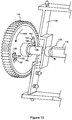
- the surfaces of drive gear 144 that form openings 192 come into contact with contact faces 188 of engagement members 186 as shown in Figure 13 .
- drive motor 70 rotates in its first rotational direction and input gear 142 rotates in rotational direction 152a
- drive shaft 134 and toner agitators 136 rotate in operative rotational direction 139 in order to mix the toner in reservoir 104 and to move toner toward auger 132.
- drive gear 144 rotates in a second rotational direction 194b as a result of the gear mesh between input gear 142 and drive gear 144.
- drive gear 144 continuously rotates independent of clutch disk 172 such that drive shaft 134 and toner agitators 136 do not rotate with drive gear 144.
- engagement members 186 of clutch disk 172 slide across outboard face 145 of drive gear 144 until engagement members 186 of clutch disk 172 reach openings 192 of drive gear 144.
- clutch disk 172 When engagement members 186 of clutch disk 172 reach openings 192 of drive gear 144, clutch disk 172 translates axially toward drive gear 144 and engagement members 186 extend into openings 192 as a result of the bias applied to clutch disk 172 by spring 174 as discussed above. However, as drive gear 144 continues to rotate in rotational direction 194b, contact between the surfaces of drive gear 144 that form openings 192 and ramps 190 of engagement members 186 cause clutch disk 172 to translate axially away from drive gear 144 against the bias applied to clutch disk 172 by spring 174 thereby causing engagement members 186 of clutch disk 172 to resume sliding across outboard face 145 of drive gear 144 as shown in Figure 14 .
- encoded member 160 rotates with input gear 142 for sensing by sensor 72, but drive shaft 134 and toner agitators 136 do not rotate with input gear 142 so that torque on drive shaft 134 and toner agitators 136 from toner stored in reservoir 104 does not interfere with the movement of encoded member 160.
- one-way clutch 170 that includes a clutch disk 172 and bias spring 174
- one or more one-way clutches of any suitable construction may be used to limit the rotational motion of at least one component of toner agitator assembly 130 to its operative rotational direction.
- the one-way clutch may include one or more of a one-way bearing sprag clutch, a trapped roller clutch, a backstop cam clutch, a pawl and ratchet clutch, and a wrap spring clutch.
- drive train 140 may take many suitable configurations for transferring rotational motion from input gear 142 to toner agitator assembly 130 and to encoded member 160.
- one or more one-way clutches may be positioned at any suitable point(s) along drive train 140 to limit the rotational motion of at least one component of toner agitator assembly 130 to its operative rotational direction.
- a first one-way clutch may be positioned to limit the motion of auger 132 to operative rotational direction 138 and a second one-way clutch may be positioned to limit the motion of drive shaft 134 and toner agitators 136 to operative rotational direction 139.
- a single one-way clutch may be positioned to limit the motion of auger 132 as well as drive shaft 134 and toner agitators 136 to their operative rotational directions 138, 139.
- Figures 15 and 16 illustrate a drive train 1140 that includes an input gear 1142 that engages with a corresponding output gear in image forming device 22.
- Drive train 1140 also includes a drive gear 1144 connected to an end of drive shaft 134 and a drive gear 1146 connected to an end of auger 132.
- Encoded member 160 is positioned on input gear 1142 as discussed above.
- a one-way clutch 1170 is operatively connected to input gear 1142 in order to limit rotation of drive gears 1144 and 1146 to a single direction to limit rotation of auger 132 and drive shaft 134 to their operative rotational directions 138, 139.
- one-way clutch 1170 includes a drive gear 1172 biased against an inboard face 1143 of input gear 1142 by a bias spring 1174.
- drive gear 1172 includes a series of circumferentially spaced, radially extending lugs 1180.
- input gear 1142 includes one or more engagement members 1186 that protrude axially from inboard face 1143 of input gear 1142 toward an outboard face 1173 of drive gear 1172.
- Each engagement member 1186 includes a contact face 1188 positioned to transfer rotational motion from input gear 1142 to drive gear 1172.
- Each engagement member 1186 also includes a ramp 1190 on inboard face 1143 of input gear 1142 that tapers axially inward (toward inboard face 1143 of input gear 1142) away from a corresponding contact face 1188 of the engagement member 1186 along a circumferential dimension of input gear 1142.
- drive gear 1172 When input gear 1142 rotates in a rotational direction 1152a, contact between contact faces 1188 of engagement members 1186 of input gear 1142 and lugs 1180 of drive gear 1172 causes drive gear 1172 to rotate with input gear 1142 as discussed above with respect to engagement members 186 of clutch disk 172 and openings 192 of drive gear 144.
- Drive gear 1144 connected to drive shaft 134 is meshed with drive gear 1172 such that rotation of drive gear 1172 causes drive gear 1144, drive shaft 134 and toner agitators 136 to rotate with input gear 1142 when input gear 1142 rotates in rotational direction 1152a.
- Drive gear 1146 is connected to drive gear 1144 by way of an idler gear 1148 and a compound idler gear 1150 such that rotation of drive gear 1172 causes drive gear 1146 and auger 132 to rotate with input gear 1142 when input gear 1142 rotates in rotational direction 1152a.
- drive gear 1142 When input gear 1142 rotates in an opposite rotational direction 1152b, contact between lugs 1180 of drive gear 1172 and ramps 1190 of engagement members 1186 of input gear 1142 cause drive gear 1172 to translate axially away from input gear 1142 against the bias applied to drive gear 1172 by spring 1174 as discussed above with respect to engagement members 186 of clutch disk 172 and openings 192 of drive gear 144. As a result, drive gear 1142 continuously rotates independent of drive gear 1172 such that auger 132, drive shaft 134 and toner agitators 136 do not rotate with input gear 1142 when input gear 1142 rotates in rotational direction 1152b.
- toner cartridge 100 may also include a one-way clutch positioned to limit rotation of encoded member 160 to a single direction as desired for reading by sensor 72.
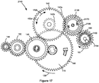
- Figure 17 illustrates encoded member 160 positioned on an outboard face 2155 of a drive gear 2154 that is coupled to input gear 142 by an idler gear 2156 and a drive gear 2158.
- Drive gear 2154, idler gear 2156 and drive gear 2158 constitute part of a drive train 2140.
- Drive train 2140 also includes input gear 142 coupled to drive gears 144, 146 by way of idler gears 148, 150 and one-way clutch 170 as discussed above with respect to Figure 7 .
- Drive train 2140 also includes a one-way clutch 2170 coupled to idler gear 2156 in order to limit rotation of drive gear 2158 to a single direction in the same manner as drive gear 1172 discussed above with respect to Figures 15 and 16 . In this manner, rotation of drive gear 2154 and encoded member 160 are limited to an operative rotational direction 161 for reading by sensor 72.
- drive motor 70 rotates in its first rotational direction and input gear 142 rotates in rotational direction 152a
- drive shaft 134 and toner agitators 136 rotate in operative rotational direction 139 but encoded member 160 does not rotate with input gear 142.
- encoded member 160 rotates in operative rotational direction 161 but drive shaft 134 and toner agitators 136 do not rotate with input gear 142.
- Figure 18 illustrates an encoded member 3160 in the form of rotatable disk 3162 that is connected to input gear 142 by a drive gear 3154.
- Disk 3162 includes a series of cutouts 3164 therethrough that are spaced along a circumferential dimension of disk 3162 according to a predetermined pattern to encode information pertaining to toner cartridge 100.
- sensor 72 includes an optical emitter and an optical detector positioned to detect the pattern of cutouts 3164 through disk 3162 as disk 3162 rotates.
- toner agitator assembly 130 may include any suitable combination of rotating, shifting, reciprocating or otherwise movable toner agitators, which may take many shapes, forms, sizes and orientations.
- the toner agitator(s) may include any suitable combination of one or more paddles, augers, rakes, combs, scoops, plows, arms, extensions, prongs, flaps, mixers, conveyors, screws, etc.
- the replaceable unit(s) of image forming device 22 may employ any suitable configuration as desired.
- the main toner supply for image forming device 22, developer unit 202 and cleaner unit 204 are housed in one replaceable unit.
- the main toner supply for image forming device 22 and developer unit 202 are provided in a first replaceable unit and cleaner unit 204 is provided in a second replaceable unit.
- the example image forming device 22 discussed above includes one toner cartridge 100 and corresponding imaging unit 200, in the case of an image forming device configured to print in color, separate replaceable units may be used for each toner color needed.
- the image forming device includes four toner cartridges and four corresponding imaging units, each toner cartridge containing a particular toner color (e.g., black, cyan, yellow or magenta) and each imaging unit corresponding with one of the toner cartridges to permit color printing.
- a particular toner color e.g., black, cyan, yellow or magenta
- each imaging unit corresponding with one of the toner cartridges to permit color printing.
- the example embodiments illustrated pertain to a toner agitator assembly 130 and an encoded member 160 of a toner cartridge 100, it will be appreciated that they may apply to a toner agitator assembly and an encoded member of any toner container including, for example, a developer unit, an imaging unit or a waste toner container.
Landscapes
- Physics & Mathematics (AREA)
- General Physics & Mathematics (AREA)
- Engineering & Computer Science (AREA)
- Computer Vision & Pattern Recognition (AREA)
- Dry Development In Electrophotography (AREA)
Abstract
Description
- The present disclosure relates generally to image forming devices and more particularly to a toner container having a common input gear for a toner agitator assembly and an encoded member.
- In electrophotographic image forming devices, one or more replaceable toner containers may be used to supply toner for printing onto sheets of media. Each toner container often includes a toner agitator assembly that agitates and mixes toner stored in a toner reservoir to prevent the toner from clumping and that moves the toner to an outlet of the toner container. It is often desired for each toner container to communicate characteristics of the toner container to the image forming device for proper operation. For example, it may be desired to communicate such information as authentication or validation information, toner fill amount, toner color, toner type, etc.
- A toner container for use in an electrophotographic image forming device according to one example embodiment includes a housing having a reservoir for storing toner. An input gear is positioned on the housing for mating with a corresponding output gear in the image forming device when the toner container is installed in the image forming device. A toner agitator is movably positioned in the reservoir. The toner agitator is operatively connected to the input gear such that rotation of the input gear in a first rotational direction causes movement of the toner agitator for agitating toner in the reservoir. An encoded member is encoded with authentication information of the toner container and is operatively connected to the input gear such that rotation of the input gear in a second rotational direction causes movement of the encoded member for communicating the authentication information of the toner container to a controller of the image forming device when the toner container is installed in the image forming device.
- In some embodiments, the toner container includes a one-way clutch positioned to decouple the toner agitator from the input gear when the input gear rotates in the second rotational direction such that the toner agitator does not move with the input gear when the input gear rotates in the second rotational direction.
- In some embodiments, the toner agitator includes a shaft rotatably positioned in the reservoir and a plurality of extensions outward from the shaft for agitating toner in the reservoir. In some embodiments, the toner agitator includes a rotatable auger positioned to move toner to an outlet port on the housing for exiting toner from the toner container.
- Embodiments include those wherein the encoded member is rotatably connected to the input gear such that rotation of the input gear in the second rotational direction causes rotation of the encoded member. In some embodiments, the encoded member is positioned on an axial face of the input gear. In some embodiments, the encoded member is coaxial with the input gear.
- In some embodiments the auger and the toner agitator may each be operatively connected to a drive gear that is directly connected to the input gear and the one-way clutch is positioned to decouple the drive gear from the input gear when the input gear rotates in the second rotational direction such that the drive gear does not rotate with the input gear when the input gear rotates in the second rotational direction
- In some embodiments, the encoded member is directly connected to the input gear. In other embodiments, the encoded member is indirectly connected to the input gear.
- Embodiments include those wherein the encoded member is encoded with authentication information of the toner container by a random distribution of magnetized particles dispersed on the encoded member.
- A toner container for use in an electrophotographic image forming device according to another example embodiment includes a housing having a reservoir for storing toner. An input gear is positioned on the housing for mating with a corresponding output gear in the image forming device when the toner container is installed in the image forming device. A toner agitator is movably positioned in the reservoir. The toner agitator is operatively connected to the input gear such that rotation of the input gear in a first rotational direction causes movement of the toner agitator for agitating toner in the reservoir. An encoded member is encoded with identifying information of the toner container and is operatively connected to the input gear such that rotation of the input gear in a second rotational direction causes movement of the encoded member for communicating the identifying information of the toner container to a sensor of the image forming device when the toner container is installed in the image forming device. A one-way clutch is positioned to decouple the toner agitator from the input gear when the input gear rotates in the second rotational direction such that the toner agitator does not move with the input gear when the input gear rotates in the second rotational direction.
- The toner agitator may include a shaft rotatably positioned in the reservoir and a plurality of extensions outward from the shaft for agitating toner in the reservoir.
- Further the toner agitator may include a rotatable auger positioned to move toner to an outlet port on the housing for exiting toner from the toner container.
- The encoded member may be rotatably connected to the input gear such that rotation of the input gear in the second rotational direction causes rotation of the encoded member. In this case the encoded member may be positioned on an axial face of the input gear or the encoded member may be coaxial with the input gear.
- In some embodiments the encoded member may be directly connected to the input gear.
- Further the encoded member may be encoded with identifying information of the toner container by a random distribution of magnetized particles dispersed on the encoded member.
- In some embodiments the auger and the toner agitator may each be operatively connected to a drive gear that is directly connected to the input gear and the one-way clutch is positioned to decouple the drive gear from the input gear when the input gear rotates in the second rotational direction such that the drive gear does not rotate with the input gear when the input gear rotates in the second rotational direction
- A toner container for use in an electrophotographic image forming device according to another example embodiment includes a housing having a reservoir for storing toner. An input gear is positioned on the housing for mating with a corresponding output gear in the image forming device when the toner container is installed in the image forming device. A toner agitator is rotatably positioned in the reservoir. The toner agitator is operatively connected to the input gear such that rotation of the input gear in a first rotational direction causes rotation of the toner agitator in an operative rotational direction of the toner agitator for agitating toner in the reservoir. An encoded member is encoded with information pertaining to the toner container and is operatively connected to the input gear such that rotation of the input gear in a second rotational direction causes movement of the encoded member for reading of the information pertaining to the toner container by a sensor when the toner container is installed in the image forming device. A one-way clutch is configured to limit rotation of the toner agitator with the input gear to the operative rotational direction of the toner agitator.
- The encoded member may be rotatably connected to the input gear such that rotation of the input gear in the second rotational direction causes rotation of the encoded member. In this case the encoded member may be positioned on an axial face of the input gear or the encoded member may be coaxial with the input gear.
- In some embodiments the encoded member may be directly connected to the input gear.
- Further the encoded member may be encoded with identifying information of the toner container by a random distribution of magnetized particles dispersed on the encoded member.
- In some embodiments the auger and the toner agitator may each be operatively connected to a drive gear that is directly connected to the input gear and the one-way clutch is positioned to decouple the drive gear from the input gear when the input gear rotates in the second rotational direction such that the drive gear does not rotate with the input gear when the input gear rotates in the second rotational direction
- A toner container for use in an electrophotographic image forming device according to another example embodiment includes a housing having a reservoir for storing toner. An input gear is positioned on the housing for mating with a corresponding output gear in the image forming device when the toner container is installed in the image forming device. An outlet port is positioned on the housing and is in fluid communication with the reservoir for exiting toner from the toner container. An auger is positioned within the housing and is operatively connected to the input gear such that rotation of the input gear in a first rotational direction causes rotation of the auger in an operative rotational direction of the auger. The auger is positioned to move toner to the outlet port when the auger rotates in the operative rotational direction of the auger. A toner agitator is positioned in the reservoir that includes a rotatable drive shaft. The toner agitator is operatively connected to the input gear such that rotation of the input gear in the first rotational direction causes rotation of the drive shaft in an operative rotational direction of the toner agitator for agitating toner in the reservoir. An encoded member is encoded with identifying information of the toner container and is operatively connected to the input gear such that rotation of the input gear in a second rotational direction causes movement of the encoded member for communicating the identifying information of the toner container to a sensor of the image forming device when the toner container is installed in the image forming device. A one-way clutch is positioned to decouple the auger and the toner agitator from the input gear when the input gear rotates in the second rotational direction such that the auger and the drive shaft do not rotate with the input gear when the input gear rotates in the second rotational direction.
- The encoded member may be rotatably connected to the input gear such that rotation of the input gear in the second rotational direction causes rotation of the encoded member. In this case the encoded member may be positioned on an axial face of the input gear or the encoded member may be coaxial with the input gear.
- In some embodiments the encoded member may be directly connected to the input gear.
- Further the encoded member may be encoded with identifying information of the toner container by a random distribution of magnetized particles dispersed on the encoded member.
- In some embodiments the auger and the toner agitator may each be operatively connected to a drive gear that is directly connected to the input gear and the one-way clutch is positioned to decouple the drive gear from the input gear when the input gear rotates in the second rotational direction such that the drive gear does not rotate with the input gear when the input gear rotates in the second rotational direction
- The accompanying drawings incorporated in and forming a part of the specification, illustrate several aspects of the present disclosure, and together with the description serve to explain the principles of the present disclosure.
-
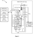
Figure 1 is a block diagram of an imaging system according to one example embodiment. -
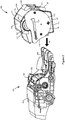
Figure 2 is a perspective view of a toner cartridge and an imaging unit according to one example embodiment. -
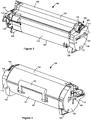
Figure 3 is a front perspective view of the toner cartridge shown inFigure 2 . -
Figure 4 is a rear perspective view of the toner cartridge shown inFigures 2 and3 . -
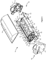
Figure 5 is an exploded view of the toner cartridge shown inFigures 2-4 showing a toner agitator assembly thereof. -
Figure 6 is a side elevation view of an encoded member of the toner cartridge according to one example embodiment. -
Figure 7 is a side elevation view of a drive train of the toner cartridge according to one example embodiment. -
Figure 8 is an exploded view of the drive train of the toner cartridge showing a one-way clutch according to one example embodiment. -
Figure 9 is an exploded view of the one-way clutch showing the engagement between the one-way clutch and a toner agitator of the toner agitator assembly according to one example embodiment. -
Figure 10 is a perspective view of a clutch disk of the one-way clutch according to one example embodiment. -
Figure 11 is a perspective view of a drive gear that engages with the clutch disk according to one example embodiment. -
Figure 12 is a perspective view of the drive gear having the one-way clutch engaged with the toner agitator according to one example embodiment. -
Figure 13 is a cross-sectional view showing the one-way clutch engaged to rotate the toner agitator when the drive gear rotates in a first direction according to one example embodiment. -
Figure 14 is a cross-sectional view showing the one-way clutch disengaged such that the toner agitator does not rotate when the drive gear rotates in a second direction according to one example embodiment. -
Figure 15 is a side elevation view of a drive train of the toner cartridge according to a second example embodiment. -
Figure 16 is an exploded view of the drive train of the toner cartridge shown inFigure 15 . -
Figure 17 is a side elevation view of a drive train of the toner cartridge according to a third example embodiment. -
Figure 18 is a side elevation view of a drive train of the toner cartridge according to a fourth example embodiment. - In the following description, reference is made to the accompanying drawings where like numerals represent like elements. The embodiments are described in sufficient detail to enable those skilled in the art to practice the present disclosure. It is to be understood that other embodiments may be utilized and that process, electrical, and mechanical changes, etc., may be made without departing from the scope of the present disclosure. Examples merely typify possible variations. Portions and features of some embodiments may be included in or substituted for those of others. The following description, therefore, is not to be taken in a limiting sense and the scope of the present disclosure is defined only by the appended claims and their equivalents.
- Referring now to the drawings and particularly to
Figure 1 , there is shown a block diagram depiction of animaging system 20 according to one example embodiment.Imaging system 20 includes animage forming device 22 and acomputer 24.Image forming device 22 communicates withcomputer 24 via acommunications link 26. As used herein, the term "communications link" generally refers to any structure that facilitates electronic communication between multiple components and may operate using wired or wireless technology and may include communications over the Internet. - In the example embodiment shown in
Figure 1 ,image forming device 22 is a multifunction machine (sometimes referred to as an all-in-one (AIO) device) that includes acontroller 28, aprint engine 30, a laser scan unit (LSU) 31, animaging unit 200, atoner cartridge 100, auser interface 36, amedia feed system 38, a media input tray 39, ascanner system 40, adrive motor 70 and asensor 72.Image forming device 22 may communicate withcomputer 24 via a standard communication protocol, such as, for example, universal serial bus (USB), Ethernet or IEEE 802.xx.Image forming device 22 may be, for example, an electrophotographic printer/copier including anintegrated scanner system 40 or a standalone electrophotographic printer. -
Controller 28 includes a processor unit and associatedelectronic memory 29. The processor may include one or more integrated circuits in the form of a microprocessor or central processing unit and may be formed as one or more application-specific integrated circuits (ASICs).Memory 29 may be any volatile or non-volatile memory or combination thereof, such as, for example, random access memory (RAM), read only memory (ROM), flash memory and/or non-volatile RAM (NVRAM).Memory 29 may be in the form of a separate memory (e.g., RAM, ROM, and/or NVRAM), a hard drive, a CD or DVD drive, or any memory device convenient for use withcontroller 28.Controller 28 may be, for example, a combined printer and scanner controller. - In the example embodiment illustrated,
controller 28 communicates withprint engine 30 via acommunications link 50.Controller 28 communicates withimaging unit 200 and processing circuitry 44 thereon via acommunications link 51.Controller 28 communicates withtoner cartridge 100 andprocessing circuitry 45 thereon via acommunications link 52.Controller 28 communicates withmedia feed system 38 via acommunications link 53.Controller 28 communicates withscanner system 40 via acommunications link 54.User interface 36 is communicatively coupled tocontroller 28 via acommunications link 55.Controller 28 communicates withdrive motor 70 via acommunications link 56.Controller 28 communicates withsensor 72 via acommunications link 57.Controller 28 processes print and scan data and operatesprint engine 30 during printing andscanner system 40 during scanning.Processing circuitry 44, 45 may provide authentication functions, safety and operational interlocks, operating parameters and usage information related toimaging unit 200 andtoner cartridge 100, respectively. Each of processingcircuitry 44, 45 includes a processor unit and associated electronic memory. As discussed above, the processor may include one or more integrated circuits in the form of a microprocessor or central processing unit and may include one or more application-specific integrated circuits (ASICs). The memory may be any volatile or non-volatile memory or combination thereof or any memory device convenient for use withprocessing circuitry 44, 45. -
Computer 24, which is optional, may be, for example, a personal computer, includingelectronic memory 60, such as RAM, ROM, and/or NVRAM, aninput device 62, such as a keyboard and/or a mouse, and adisplay monitor 64.Computer 24 also includes a processor, input/output (I/O) interfaces, and may include at least one mass data storage device, such as a hard drive, a CD-ROM and/or a DVD unit (not shown).Computer 24 may also be a device capable of communicating withimage forming device 22 other than a personal computer such as, for example, a tablet computer, a smartphone, or other electronic device. - In the example embodiment illustrated,
computer 24 includes in its memory a software program including program instructions that function as animaging driver 66, e.g., printer/scanner driver software, forimage forming device 22.Imaging driver 66 is in communication withcontroller 28 ofimage forming device 22 via communications link 26.Imaging driver 66 facilitates communication betweenimage forming device 22 andcomputer 24. One aspect ofimaging driver 66 may be, for example, to provide formatted print data to image formingdevice 22, and more particularly to printengine 30, to print an image. Another aspect ofimaging driver 66 may be, for example, to facilitate collection of scanned data fromscanner system 40. - In some circumstances, it may be desirable to operate
image forming device 22 in a standalone mode. In the standalone mode,image forming device 22 is capable of functioning withoutcomputer 24. Accordingly, all or a portion ofimaging driver 66, or a similar driver, may be located incontroller 28 ofimage forming device 22 so as to accommodate printing and/or scanning functionality when operating in the standalone mode. -
Print engine 30 includes a laser scan unit (LSU) 31,toner cartridge 100,imaging unit 200 and afuser 37, all mounted withinimage forming device 22.Imaging unit 200 is removably mounted inimage forming device 22 and includes adeveloper unit 202 that houses a toner sump and a toner development system. In one embodiment, the toner development system utilizes what is commonly referred to as a single component development system. In this embodiment, the toner development system includes a toner adder roll that provides toner from the toner sump to a developer roll. A doctor blade provides a metered uniform layer of toner on the surface of the developer roll. In another embodiment, the toner development system utilizes what is commonly referred to as a dual component development system. In this embodiment, toner in the toner sump ofdeveloper unit 202 is mixed with magnetic carrier beads. The magnetic carrier beads may be coated with a polymeric film to provide triboelectric properties to attract toner to the carrier beads as the toner and the magnetic carrier beads are mixed in the toner sump. In this embodiment,developer unit 202 includes a magnetic roll that attracts the magnetic carrier beads having toner thereon to the magnetic roll through the use of magnetic fields.Imaging unit 200 also includes acleaner unit 204 that houses a photoconductive drum and a waste toner removal system. -
Toner cartridge 100 is removably mounted inimaging forming device 22 in a mating relationship withdeveloper unit 202 ofimaging unit 200. An outlet port ontoner cartridge 100 communicates with an inlet port ondeveloper unit 202 allowing toner to be periodically transferred fromtoner cartridge 100 to resupply the toner sump indeveloper unit 202. - The electrophotographic printing process is well known in the art and, therefore, is described briefly herein. During a printing operation,
laser scan unit 31 creates a latent image on the photoconductive drum incleaner unit 204. Toner is transferred from the toner sump indeveloper unit 202 to the latent image on the photoconductive drum by the developer roll (in the case of a single component development system) or by the magnetic roll (in the case of a dual component development system) to create a toned image. The toned image is then transferred to a media sheet received byimaging unit 200 from media input tray 39 for printing. Toner may be transferred directly to the media sheet by the photoconductive drum or by an intermediate transfer member that receives the toner from the photoconductive drum. Toner remnants are removed from the photoconductive drum by the waste toner removal system. The toner image is bonded to the media sheet infuser 37 and then sent to an output location or to one or more finishing options such as a duplexer, a stapler or a hole-punch. - Referring now to
Figure 2 ,toner cartridge 100 andimaging unit 200 are shown according to one example embodiment.Imaging unit 200 includes adeveloper unit 202 and acleaner unit 204 mounted on acommon frame 206.Developer unit 202 includes atoner inlet port 208 positioned to receive toner fromtoner cartridge 100. As discussed above,imaging unit 200 andtoner cartridge 100 are each removably installed inimage forming device 22.Imaging unit 200 is first slidably inserted intoimage forming device 22.Toner cartridge 100 is then inserted intoimage forming device 22 and ontoframe 206 in a mating relationship withdeveloper unit 202 ofimaging unit 200 as indicated by the arrow A shown inFigure 2 , which also indicates the direction of insertion ofimaging unit 200 andtoner cartridge 100 intoimage forming device 22. This arrangement allowstoner cartridge 100 to be removed and reinserted easily when replacing anempty toner cartridge 100 without having to removeimaging unit 200.Imaging unit 200 may also be readily removed as desired in order to maintain, repair or replace the components associated withdeveloper unit 202,cleaner unit 204 orframe 206 or to clear a media jam. - With reference to
Figures 2-5 ,toner cartridge 100 includes ahousing 102 having an enclosed reservoir 104 (Figure 5 ) for storing toner.Housing 102 includes a top 106, a bottom 107, first andsecond sides Front 110 ofhousing 102 leads during insertion oftoner cartridge 100 intoimage forming device 22 and rear 111 trails. In one embodiment, eachside housing 102 includes anend cap side walls main body 116 ofhousing 102. Anoutlet port 118 in fluid communication withreservoir 104 is positioned onfront 110 ofhousing 102 nearside 109 for exiting toner fromtoner cartridge 100.Housing 102 may includelegs 120 onbottom 107 to assist with the insertion oftoner cartridge 100 intoimage forming device 22 and to supporthousing 102 whentoner cartridge 100 is set on a flat surface. Ahandle 122 may be provided on top 106 or rear 111 ofhousing 102 to assist with insertion and removal oftoner cartridge 100 into and out ofimage forming device 22. -
Sides alignment guide 124 that extends outward from therespective side toner cartridge 100 intoimage forming device 22. Alignment guides 124 travel in corresponding guide slots inimage forming device 22 that guide the insertion oftoner cartridge 100 intoimage forming device 22. In the example embodiment illustrated, analignment guide 124 is positioned on the outer side of eachend cap housing 102 as shown inFigures 2-4 . - With reference to
Figure 5 , in the example embodiment illustrated, atoner agitator assembly 130 is rotatably positioned withintoner reservoir 104.Toner agitator assembly 130 includes anauger 132 having first andsecond ends Auger 132 is positioned in achannel 128 that runs along thefront 110 ofhousing 102 fromside 108 toside 109.Channel 128 is oriented generally horizontal whentoner cartridge 100 is installed inimage forming device 22.Auger 132 includes arotational axis 133. In operation,auger 132 rotates in an operativerotational direction 138. Rotation ofauger 132 delivers toner inchannel 128 tooutlet port 118, which is positioned at the bottom ofchannel 128 so that gravity assists in exiting toner throughoutlet port 118.Channel 128 includes anopen portion 128a and may include anenclosed portion 128b.Open portion 128a is open totoner reservoir 104 and extends fromside 108 towardsecond end 132b ofauger 132.Enclosed portion 128b ofchannel 128 extends fromside 109 and enclosessecond end 132b ofauger 132. In this embodiment,outlet port 118 is positioned at the bottom ofenclosed portion 128b ofchannel 128. -
Toner agitator assembly 130 also includes arotatable drive shaft 134 and one ormore toner agitators 136 in the form of extensions outward fromdrive shaft 134. Driveshaft 134 includes arotational axis 135. In the example embodiment illustrated,rotational axis 135 ofdrive shaft 134 is parallel torotational axis 133 ofauger 132. In operation, driveshaft 134 rotates in an operativerotational direction 139.Toner agitators 136 rotate withdrive shaft 134 aroundrotational axis 135 whendrive shaft 134 rotates in operativerotational direction 139. Asdrive shaft 134 rotates,toner agitators 136 agitate and mix the toner stored intoner reservoir 104 and, in the embodiment illustrated, move toner towardchannel 128 whereauger 132 moves the toner tooutlet port 118. In the example embodiment illustrated, first and second ends ofdrive shaft 134 extend through aligned openings inside walls drive shaft 134 may take other positions and orientations as desired. Bushings may be provided on an inner side of eachside wall drive shaft 134 passes throughside walls - A
drive train 140 onhousing 102 is operatively connected to auger 132 and driveshaft 134 and may be positioned within a space formed betweenend cap 112 andside wall 114. Drivetrain 140 includes aninput gear 142 that engages with a corresponding output gear inimage forming device 22 that provides rotational motion fromdrive motor 70 inimage forming device 22 to inputgear 142. As shown inFigure 3 , in one embodiment, a front portion ofinput gear 142 is exposed at thefront 110 ofhousing 102 near the top 106 ofhousing 102 whereinput gear 142 engages the output gear inimage forming device 22. With reference back toFigure 5 , in the embodiment illustrated,drive train 140 also includes adrive gear 144 on one end ofdrive shaft 134 that is connected to inputgear 142 either directly or via one or more intermediate gears to rotatedrive shaft 134. In the embodiment illustrated,drive train 140 also includes adrive gear 146 onfirst end 132a ofauger 132 that is connected to inputgear 142 either directly or via one or more intermediate gears to rotateauger 132. - With reference to
Figures 5 and6 ,toner cartridge 100 includes an encodedmember 160 that is movably connected to drivetrain 140, either directly or indirectly to inputgear 142. In the example embodiment illustrated, encodedmember 160 includes arotatable disk 162 operatively connected to drivetrain 140, such as, for example, positioned on anoutboard face 143 ofinput gear 142, coaxially withinput gear 142 as illustrated.Disk 162 may be formed integrally withinput gear 142 or separately attached to inputgear 142. In other embodiments, encodedmember 160 is, for example, translatable, such as by way of a rack and pinion arrangement or a cam and follower arrangement. Information pertaining totoner cartridge 100 is encoded on encodedmember 160. Encodedmember 160 is detectable bysensor 72 inimage forming device 22 whentoner cartridge 100 is installed inimage forming device 22 permittingsensor 72 to communicate the encoded information oftoner cartridge 100 tocontroller 28 ofimage forming device 22 via communications link 57. The encoded information may include, for example, authentication information such as a signature, serial number, or other identifier for authenticating or validatingtoner cartridge 100 upon installation oftoner cartridge 100 inimage forming device 22. The encoded information may include, for example, characteristics oftoner cartridge 100 such as toner color, initial toner fill amount, toner type, geographic region, manufacture location, manufacture date, etc. - In the example embodiment illustrated, authentication information is encoded on encoded
member 160 by randomly distributedmagnetized particles 164 dispersed ondisk 162, e.g., on the surface ofdisk 162 and/or withindisk 162.Particles 164 are distributed randomly such that it is difficult to reproduce the exact distribution and alignment ofparticles 164 thereby making the distribution difficult to copy. In this embodiment,sensor 72 is positioned in close proximity to encodedmember 62 whentoner cartridge 100 is installed inimage forming device 22, such as, adjacent to and facing the outboard side ofdisk 162 as schematically illustrated inFigure 6 . At predetermined times, such as upon the installation of a new toner cartridge inimage forming device 22,sensor 72 measures the magnetic field ofdisk 162 in one, two or three dimensions asdisk 162 rotates due to rotation ofinput gear 142 bymotor 70. The magnetic field values measured bysensor 72 are communicated tocontroller 28 via communications link 57.Controller 28 may then compare the magnetic field values received fromsensor 72 to values stored during manufacture in non-volatile memory ofprocessing circuitry 45 oftoner cartridge 100.Controller 28 may confirm the authenticity oftoner cartridge 100 tocontroller 28 if the magnetic field values received fromsensor 72 match the values stored in non-volatile memory ofprocessing circuitry 45. - While the example embodiment illustrated includes information encoded by a random distribution of magnetized particles and detection by measuring the magnetic field of the particles, it will be appreciated that information may be encoded by a random distribution of non-magnetized particles and detection may occur according to other means, such as, for example, by measuring an optical property of the particles. Further, in lieu of a random pattern, information may be encoded according to a predetermined pattern using any suitable indicia and detection method. However, as discussed above, it is preferred for authentication information to be encoded according to a random pattern so that the encoded information is more difficult for a counterfeiter to reproduce.
- With reference back to
Figures 2 and3 , in the example embodiment illustrated, at least a portion of encodedmember 160 is exposed on the exterior oftoner cartridge 100 above arotational axis 141 ofinput gear 142 for reading bysensor 72. For example, in the embodiment illustrated, encodedmember 160 is exposed through acutout 166 inend cap 112 that is positioned aboverotational axis 141 ofinput gear 142. -
Figure 7 shows drivetrain 140 in greater detail according to one example embodiment. In the example embodiment illustrated,input gear 142 is a compound gear that includes afirst portion 142a that mates with the corresponding output gear inimage forming device 22 whentoner cartridge 100 is installed inimage forming device 22 and asecond portion 142b that meshes withdrive gear 144 in order to provide rotational motion to driveshaft 134.First portion 142a ofinput gear 142 also meshes with anidler gear 148 that, in turn, meshes with acompound idler gear 150.Compound idler gear 150 includes afirst portion 150a that meshes withidler gear 148 and asecond portion 150b that meshes withdrive gear 146 in order to provide rotational motion to auger 132. It will be appreciated that the embodiment illustrated inFigure 7 is merely an example and thatdrive train 140 may take many suitable configurations for transferring rotational motion frominput gear 142 totoner agitator assembly 130 and to encodedmember 160. - In operation,
controller 28 drives motor 70 in a first rotational direction to drivetoner agitator assembly 130 and in a second rotational direction to perform a reading of encodedmember 160 bysensor 72. In particular, whencontroller 28 drives motor 70 in the first rotational direction,input gear 142 rotates in a firstrotational direction 152a and, in turn, rotatesauger 132 and driveshaft 134 in operativerotational directions toner cartridge 100 todeveloper unit 202. Whencontroller 28 drives motor 70 in the second rotational direction,input gear 142 rotates in a secondrotational direction 152b.Sensor 72 is configured to read encodedmember 160 asinput gear 142 rotates inrotational direction 152b. In this manner,sensor 72 is able to perform a reading of encodedmember 160 separately from a toner feed operation so that the authenticity or validity oftoner cartridge 100 may be checked prior to the first use oftoner cartridge 100 or at other times whentoner cartridge 100 is not in use. - With reference to
Figure 8 ,toner agitator assembly 130 includes a one-way clutch 170 that limits the rotational motion of at least one component oftoner agitator assembly 130 to its operative rotational direction. For example, the one-way clutch may limitauger 132 and/or driveshaft 134 to its operativerotational direction way clutch 170 is operatively connected to drivegear 144 such that wheninput gear 142 rotates inrotational direction 152a,drive shaft 134 rotates in operativerotational direction 139 and wheninput gear 142 rotates inrotational direction 152b,drive shaft 134 is decoupled and does not rotate withinput gear 142. In this manner,drive shaft 134 andtoner agitators 136 do not rotate whilesensor 72 performs a reading of encodedmember 160. As a result, torque ondrive shaft 134 andtoner agitators 136 from toner stored inreservoir 104 does not affect the movement of encodedmember 160 thereby permitting better control of encodedmember 160 whilesensor 72 performs a reading of encodedmember 160 and improving the accuracy of the reading performed bysensor 72. Further, in some embodiments,toner agitators 136 may include flexible wipers that could displace or become damaged upon rotating counter to operativerotational direction 139.Decoupling drive shaft 134 frominput gear 142 wheninput gear 142 rotates inrotational direction 152b prevents this from occurring. - In the example embodiment illustrated, one-
way clutch 170 includes aclutch disk 172 positioned against anoutboard face 145 ofdrive gear 144.Clutch disk 172 is biased againstoutboard face 145 ofdrive gear 144 by abias spring 174. Abracket 176 positioned betweenend cap 112 andside wall 114 locatesspring 174 relative toclutch disk 172 and drivegear 144. In the example embodiment illustrated,bracket 176 also locatesinput gear 142 relative to endcap 112 and to the rest ofdrive train 140. - With reference to
Figure 9 , in the example embodiment illustrated,drive shaft 134 includes amale spline 178 positioned near an axial end ofdrive shaft 134.Male spline 178 passes through alignedcentral openings drive gear 144 andclutch disk 172, respectively. A diameter ofcentral opening 180 ofdrive gear 144 is larger thanmale spline 178 ofdrive shaft 134 permittingdrive gear 144 to rotate independent ofdrive shaft 134.Central opening 182 ofclutch disk 172 includes afemale spline 184 that matably receivesmale spline 178 ofdrive shaft 134 such that driveshaft 134 is rotatably coupled toclutch disk 172. - With reference to
Figure 10 ,clutch disk 172 includes one ormore engagement members 186 that protrude axially from aninboard face 173 ofclutch disk 172 towardoutboard face 145 ofdrive gear 144. Eachengagement member 186 includes acontact face 188 positioned to transfer rotational motion fromclutch disk 172 to drivegear 144. In the embodiment illustrated, contact faces 188 are positioned perpendicular toinboard face 173 ofclutch disk 172; however, contact faces 188 may take other suitable orientations as desired. Eachengagement member 186 also includes aramp 190 oninboard face 173 ofclutch disk 172 that tapers axially inward (towardinboard face 173 of clutch disk 172) away from acorresponding contact face 188 of theengagement member 186 along a circumferential dimension ofclutch disk 172. -
Engagement members 186 ofclutch disk 172 are positioned to engage corresponding dwells oropenings 192 ondrive gear 144 shown inFigure 11 to transfer rotational motion fromdrive gear 144 toclutch disk 172 wheninput gear 142 rotates inrotational direction 152a. Specifically, with reference toFigures 12 and13 , wheninput gear 142 rotates inrotational direction 152a,drive gear 144 rotates in a firstrotational direction 194a as a result of the gear mesh betweeninput gear 142 and drivegear 144. Asdrive gear 144 rotates inrotational direction 194a,drive gear 144 rotates independent ofclutch disk 172 withengagement members 186 ofclutch disk 172 sliding acrossoutboard face 145 ofdrive gear 144 untilengagement members 186 ofclutch disk 172reach openings 192 ofdrive gear 144. Whenengagement members 186 ofclutch disk 172reach openings 192 ofdrive gear 144,clutch disk 172 translates axially towarddrive gear 144 andengagement members 186 extend intoopenings 192 as a result of the bias applied toclutch disk 172 byspring 174. Asdrive gear 144 continues to rotate inrotational direction 194a, the surfaces ofdrive gear 144 that formopenings 192 come into contact with contact faces 188 ofengagement members 186 as shown inFigure 13 . The contact between contact faces 188 ofengagement members 186 ofclutch disk 172 and thesurfaces forming openings 192 ofdrive gear 144 transfer rotational motion fromdrive gear 144 toclutch disk 172 causingclutch disk 172 to rotate withdrive gear 144 asdrive gear 144 continues to rotate inrotational direction 194a. The engagement betweenmale spline 178 ofdrive shaft 134 andfemale spline 184 ofclutch disk 172, in turn, causes driveshaft 134 andtoner agitators 136 to rotate withclutch disk 172. In this manner, whendrive motor 70 rotates in its first rotational direction andinput gear 142 rotates inrotational direction 152a,drive shaft 134 andtoner agitators 136 rotate in operativerotational direction 139 in order to mix the toner inreservoir 104 and to move toner towardauger 132. - With reference to
Figures 12 and14 , wheninput gear 142 rotates in the oppositerotational direction 152b,drive gear 144 rotates in a secondrotational direction 194b as a result of the gear mesh betweeninput gear 142 and drivegear 144. Asdrive gear 144 rotates inrotational direction 194b,drive gear 144 continuously rotates independent ofclutch disk 172 such that driveshaft 134 andtoner agitators 136 do not rotate withdrive gear 144. Specifically, asdrive gear 144 rotates inrotational direction 194b,engagement members 186 ofclutch disk 172 slide acrossoutboard face 145 ofdrive gear 144 untilengagement members 186 ofclutch disk 172reach openings 192 ofdrive gear 144. Whenengagement members 186 ofclutch disk 172reach openings 192 ofdrive gear 144,clutch disk 172 translates axially towarddrive gear 144 andengagement members 186 extend intoopenings 192 as a result of the bias applied toclutch disk 172 byspring 174 as discussed above. However, asdrive gear 144 continues to rotate inrotational direction 194b, contact between the surfaces ofdrive gear 144 that formopenings 192 andramps 190 ofengagement members 186 causeclutch disk 172 to translate axially away fromdrive gear 144 against the bias applied toclutch disk 172 byspring 174 thereby causingengagement members 186 ofclutch disk 172 to resume sliding acrossoutboard face 145 ofdrive gear 144 as shown inFigure 14 . In this manner, whendrive motor 70 rotates in its second rotational direction andinput gear 142 rotates inrotational direction 152b, encodedmember 160 rotates withinput gear 142 for sensing bysensor 72, but driveshaft 134 andtoner agitators 136 do not rotate withinput gear 142 so that torque ondrive shaft 134 andtoner agitators 136 from toner stored inreservoir 104 does not interfere with the movement of encodedmember 160. - While the example embodiment illustrated in
Figures 8-14 includes a one-way clutch 170 that includes aclutch disk 172 andbias spring 174, one or more one-way clutches of any suitable construction may be used to limit the rotational motion of at least one component oftoner agitator assembly 130 to its operative rotational direction. For example, the one-way clutch may include one or more of a one-way bearing sprag clutch, a trapped roller clutch, a backstop cam clutch, a pawl and ratchet clutch, and a wrap spring clutch. - As discussed above,
drive train 140 may take many suitable configurations for transferring rotational motion frominput gear 142 totoner agitator assembly 130 and to encodedmember 160. Further, while the exampled embodiment illustrated includes a one-way clutch 170 positioned ondrive gear 144 connected to driveshaft 134, one or more one-way clutches may be positioned at any suitable point(s) alongdrive train 140 to limit the rotational motion of at least one component oftoner agitator assembly 130 to its operative rotational direction. For example, a first one-way clutch may be positioned to limit the motion ofauger 132 to operativerotational direction 138 and a second one-way clutch may be positioned to limit the motion ofdrive shaft 134 andtoner agitators 136 to operativerotational direction 139. Alternatively, a single one-way clutch may be positioned to limit the motion ofauger 132 as well asdrive shaft 134 andtoner agitators 136 to their operativerotational directions - For example,
Figures 15 and16 illustrate adrive train 1140 that includes aninput gear 1142 that engages with a corresponding output gear inimage forming device 22.Drive train 1140 also includes adrive gear 1144 connected to an end ofdrive shaft 134 and adrive gear 1146 connected to an end ofauger 132. Encodedmember 160 is positioned oninput gear 1142 as discussed above. In this embodiment, a one-way clutch 1170 is operatively connected to inputgear 1142 in order to limit rotation of drive gears 1144 and 1146 to a single direction to limit rotation ofauger 132 and driveshaft 134 to their operativerotational directions drive gear 1172 biased against aninboard face 1143 ofinput gear 1142 by abias spring 1174. Abracket 1176 positioned betweenend cap 112 andside wall 114 locatesspring 1174 relative to drivegear 1172. In this embodiment,drive gear 1172 includes a series of circumferentially spaced, radially extendinglugs 1180. In this embodiment,input gear 1142 includes one ormore engagement members 1186 that protrude axially frominboard face 1143 ofinput gear 1142 toward anoutboard face 1173 ofdrive gear 1172. Eachengagement member 1186 includes acontact face 1188 positioned to transfer rotational motion frominput gear 1142 to drivegear 1172. Eachengagement member 1186 also includes aramp 1190 oninboard face 1143 ofinput gear 1142 that tapers axially inward (towardinboard face 1143 of input gear 1142) away from acorresponding contact face 1188 of theengagement member 1186 along a circumferential dimension ofinput gear 1142. - When
input gear 1142 rotates in arotational direction 1152a, contact between contact faces 1188 ofengagement members 1186 ofinput gear 1142 and lugs 1180 ofdrive gear 1172 causes drivegear 1172 to rotate withinput gear 1142 as discussed above with respect toengagement members 186 ofclutch disk 172 andopenings 192 ofdrive gear 144.Drive gear 1144 connected to driveshaft 134 is meshed withdrive gear 1172 such that rotation ofdrive gear 1172 causes drivegear 1144,drive shaft 134 andtoner agitators 136 to rotate withinput gear 1142 wheninput gear 1142 rotates inrotational direction 1152a.Drive gear 1146 is connected to drivegear 1144 by way of anidler gear 1148 and acompound idler gear 1150 such that rotation ofdrive gear 1172 causes drivegear 1146 andauger 132 to rotate withinput gear 1142 wheninput gear 1142 rotates inrotational direction 1152a. - When
input gear 1142 rotates in an oppositerotational direction 1152b, contact betweenlugs 1180 ofdrive gear 1172 andramps 1190 ofengagement members 1186 ofinput gear 1142cause drive gear 1172 to translate axially away frominput gear 1142 against the bias applied to drivegear 1172 byspring 1174 as discussed above with respect toengagement members 186 ofclutch disk 172 andopenings 192 ofdrive gear 144. As a result,drive gear 1142 continuously rotates independent ofdrive gear 1172 such thatauger 132,drive shaft 134 andtoner agitators 136 do not rotate withinput gear 1142 wheninput gear 1142 rotates inrotational direction 1152b. - While the example embodiments illustrated include a one-way clutch to limit the rotational motion of at least one component of
toner agitator assembly 130 to its operative rotational direction,toner cartridge 100 may also include a one-way clutch positioned to limit rotation of encodedmember 160 to a single direction as desired for reading bysensor 72. For example,Figure 17 illustrates encodedmember 160 positioned on anoutboard face 2155 of adrive gear 2154 that is coupled toinput gear 142 by anidler gear 2156 and adrive gear 2158.Drive gear 2154,idler gear 2156 and drivegear 2158 constitute part of adrive train 2140.Drive train 2140 also includesinput gear 142 coupled to drivegears Figure 7 .Drive train 2140 also includes a one-way clutch 2170 coupled toidler gear 2156 in order to limit rotation ofdrive gear 2158 to a single direction in the same manner asdrive gear 1172 discussed above with respect toFigures 15 and16 . In this manner, rotation ofdrive gear 2154 and encodedmember 160 are limited to an operativerotational direction 161 for reading bysensor 72. Specifically, in this embodiment, whendrive motor 70 rotates in its first rotational direction andinput gear 142 rotates inrotational direction 152a,drive shaft 134 andtoner agitators 136 rotate in operativerotational direction 139 but encodedmember 160 does not rotate withinput gear 142. When drivemotor 70 rotates in its second rotational direction andinput gear 142 rotates inrotational direction 152b, encodedmember 160 rotates in operativerotational direction 161 but driveshaft 134 andtoner agitators 136 do not rotate withinput gear 142. - As discussed above, while the example embodiments illustrated include an encoded
member 160 that includes information encoded by a random distribution of magnetized particles, information may be encoded on an encoded member that is movably connected to an input gear oftoner cartridge 100 according to many other suitable methods. For example,Figure 18 illustrates an encodedmember 3160 in the form ofrotatable disk 3162 that is connected to inputgear 142 by adrive gear 3154.Disk 3162 includes a series ofcutouts 3164 therethrough that are spaced along a circumferential dimension ofdisk 3162 according to a predetermined pattern to encode information pertaining totoner cartridge 100. In this embodiment,sensor 72 includes an optical emitter and an optical detector positioned to detect the pattern ofcutouts 3164 throughdisk 3162 asdisk 3162 rotates. - While the example embodiments discussed above include a
toner agitator assembly 130 that includes arotatable auger 132 and arotatable drive shaft 134 havingtoner agitators 136 extending outward therefrom, it will be appreciated thattoner agitator assembly 130 may include any suitable combination of rotating, shifting, reciprocating or otherwise movable toner agitators, which may take many shapes, forms, sizes and orientations. For example, the toner agitator(s) may include any suitable combination of one or more paddles, augers, rakes, combs, scoops, plows, arms, extensions, prongs, flaps, mixers, conveyors, screws, etc. - While the example embodiment shown in
Figure 2 includes a pair of replaceable units in the form oftoner cartridge 100 andimaging unit 200, it will be appreciated that the replaceable unit(s) ofimage forming device 22 may employ any suitable configuration as desired. For example, in one embodiment, the main toner supply forimage forming device 22,developer unit 202 andcleaner unit 204 are housed in one replaceable unit. In another embodiment, the main toner supply forimage forming device 22 anddeveloper unit 202 are provided in a first replaceable unit andcleaner unit 204 is provided in a second replaceable unit. Further, while the exampleimage forming device 22 discussed above includes onetoner cartridge 100 andcorresponding imaging unit 200, in the case of an image forming device configured to print in color, separate replaceable units may be used for each toner color needed. For example, in one embodiment, the image forming device includes four toner cartridges and four corresponding imaging units, each toner cartridge containing a particular toner color (e.g., black, cyan, yellow or magenta) and each imaging unit corresponding with one of the toner cartridges to permit color printing. Further, while the example embodiments illustrated pertain to atoner agitator assembly 130 and an encodedmember 160 of atoner cartridge 100, it will be appreciated that they may apply to a toner agitator assembly and an encoded member of any toner container including, for example, a developer unit, an imaging unit or a waste toner container. - The foregoing description illustrates various aspects of the present disclosure. It is not intended to be exhaustive. Rather, it is chosen to illustrate the principles of the present disclosure and its practical application to enable one of ordinary skill in the art to utilize the present disclosure, including its various modifications that naturally follow. All modifications and variations are contemplated within the scope of the present disclosure as determined by the appended claims. Relatively apparent modifications include combining one or more features of various embodiments with features of other embodiments.
Claims (10)
- A toner container for use in an electrophotographic image forming device, comprising:a housing having a reservoir for storing toner;an input gear positioned on the housing for mating with a corresponding output gear in the image forming device when the toner container is installed in the image forming device;a toner agitator movably positioned in the reservoir, the toner agitator is operatively connected to the input gear such that rotation of the input gear in a first rotational direction causes movement of the toner agitator for agitating toner in the reservoir; andan encoded member encoded with authentication information of the toner container and operatively connected to the input gear such that rotation of the input gear in a second rotational direction causes movement of the encoded member for communicating the authentication information of the toner container to a controller of the image forming device when the toner container is installed in the image forming device.
- The toner container of claim 1, wherein the toner agitator includes a shaft rotatably positioned in the reservoir and a plurality of extensions outward from the shaft for agitating toner in the reservoir.
- The toner container of any one of the preceding claims, wherein the encoded member is rotatably connected to the input gear such that rotation of the input gear in the second rotational direction causes rotation of the encoded member.
- The toner container of claim 3, wherein the encoded member is positioned on an axial face of the input gear.
- The toner container of claim 3 or claim 4, wherein the encoded member is coaxial with the input gear.
- The toner container of any one of the preceding claims, wherein the encoded member is directly connected to the input gear.
- The toner container of any one of the preceding claims, wherein the encoded member is encoded with authentication information of the toner container by a random distribution of magnetized particles dispersed on the encoded member.
- The toner container of any one of the preceding claims, further comprising a one-way clutch positioned to decouple the toner agitator from the input gear when the input gear rotates in the second rotational direction such that the toner agitator does not move with the input gear when the input gear rotates in the second rotational direction.
- The toner container of any one of the preceding claims, wherein the toner agitator includes a rotatable auger positioned to move toner to an outlet port on the housing for exiting toner from the toner container.
- The toner container of claim 9 in combination with claim 8, wherein the auger and the toner agitator are each operatively connected to a drive gear that is directly connected to the input gear and the one-way clutch is positioned to decouple the drive gear from the input gear when the input gear rotates in the second rotational direction such that the drive gear does not rotate with the input gear when the input gear rotates in the second rotational direction.
Applications Claiming Priority (1)
| Application Number | Priority Date | Filing Date | Title |
|---|---|---|---|
| US16/157,495 US10527967B1 (en) | 2018-10-11 | 2018-10-11 | Toner container having a common input gear for a toner agitator assembly and an encoded member |
Publications (2)
| Publication Number | Publication Date |
|---|---|
| EP3637191A1 true EP3637191A1 (en) | 2020-04-15 |
| EP3637191B1 EP3637191B1 (en) | 2025-04-16 |
Family
ID=68242493
Family Applications (1)
| Application Number | Title | Priority Date | Filing Date |
|---|---|---|---|
| EP19202276.2A Active EP3637191B1 (en) | 2018-10-11 | 2019-10-09 | Toner container having a common input gear for a toner agitator assembly and an encoded member |
Country Status (5)
| Country | Link |
|---|---|
| US (4) | US10527967B1 (en) |
| EP (1) | EP3637191B1 (en) |
| CN (1) | CN112839823B (en) |
| CA (1) | CA3112192C (en) |
| WO (1) | WO2020076457A1 (en) |
Cited By (2)
| Publication number | Priority date | Publication date | Assignee | Title |
|---|---|---|---|---|
| WO2020197844A1 (en) | 2019-03-22 | 2020-10-01 | Lexmark International, Inc. | Toner container having an encoded member and an alignment guide for locating a sensor relative to the encoded member |
| EP3942370A4 (en) * | 2019-03-22 | 2022-12-14 | Lexmark International, Inc. | TONER CONTAINER WITH CODED ELEMENT AND ALIGNMENT GUIDE TO LOCATE SENSOR IN RELATION TO CODED ELEMENT |
Families Citing this family (8)
| Publication number | Priority date | Publication date | Assignee | Title |
|---|---|---|---|---|
| US10527967B1 (en) * | 2018-10-11 | 2020-01-07 | Lexmark International, Inc. | Toner container having a common input gear for a toner agitator assembly and an encoded member |
| US11022909B2 (en) | 2018-10-11 | 2021-06-01 | Lexmark International, Inc. | Toner container having an encoded member and an alignment guide for locating a sensor relative to the encoded member |
| US11022910B2 (en) | 2018-10-11 | 2021-06-01 | Lexmark International, Inc. | Sensor positioning by a replaceable unit of an image forming device |
| USD952030S1 (en) * | 2019-10-23 | 2022-05-17 | Lexmark International, Inc. | Toner cartridge |
| US11137699B1 (en) | 2020-06-01 | 2021-10-05 | Lexmark International, Inc. | Toner container having a reduced auger flight to accommodate bi-directional rotation of the auger |
| JP7622392B2 (en) * | 2020-08-25 | 2025-01-28 | ブラザー工業株式会社 | Image forming apparatus and control method thereof |
| JP7765737B2 (en) * | 2021-03-31 | 2025-11-07 | 株式会社リコー | Toner container and image forming apparatus |
| US11550259B1 (en) * | 2021-10-06 | 2023-01-10 | Lexmark International, Inc. | Image forming device having a replaceable unit including a retractable encoded member |
Citations (4)
| Publication number | Priority date | Publication date | Assignee | Title |
|---|---|---|---|---|
| JP2005099434A (en) * | 2003-09-25 | 2005-04-14 | Kyocera Mita Corp | Toner container and image forming apparatus provided with the same |
| KR20090031062A (en) * | 2007-09-21 | 2009-03-25 | 김희성 | Toner cartridge with auxiliary stirring means |
| US20160077466A1 (en) * | 2014-06-02 | 2016-03-17 | Lexmark International, Inc. | Replaceable Unit for an Image Forming Device Having Magnets of Varying Angular Offset for Toner Level Sensing |
| US20170103834A1 (en) * | 2015-10-09 | 2017-04-13 | Lexmark International, Inc. | Methods of Making Physical Unclonable Functions Having Magnetic and Non-Magnetic Particles |
Family Cites Families (40)
| Publication number | Priority date | Publication date | Assignee | Title |
|---|---|---|---|---|
| US4074798A (en) * | 1976-09-01 | 1978-02-21 | Xerox Corporation | Encoded print wheel system |
| US5634169A (en) | 1996-02-16 | 1997-05-27 | Lexmark International, Inc. | Multiple function encoder wheel for cartridges utilized in an electrophotographic output device |
| BR9700989C1 (en) * | 1996-02-16 | 2000-04-25 | Lexmark Int Inc | Cartridge for an electrophotographic machine |
| US5995772A (en) * | 1996-02-16 | 1999-11-30 | Lexmark International Inc. | Imaging apparatus cartridge including an encoded device |
| US6100601A (en) | 1999-08-11 | 2000-08-08 | Lexmark International, Inc. | Measurement of toner level employing sensor on paddle |
| US6510303B2 (en) * | 2001-03-15 | 2003-01-21 | Clarity Imaging Technologies | Extended-life toner cartridge for a laser printer |
| US6510291B2 (en) | 2001-04-19 | 2003-01-21 | Lexmark International, Inc | Toner supply with level sensor and meter and method of using the same |
| US6580881B2 (en) | 2001-10-04 | 2003-06-17 | Lexmark International, Inc. | Method of detecting waste toner in a container of an image forming apparatus |
| US6496662B1 (en) | 2002-06-19 | 2002-12-17 | Lexmark International, Inc. | Optical toner low sensor |
| KR100477661B1 (en) * | 2002-09-06 | 2005-03-23 | 삼성전자주식회사 | Wasted toner storing apparatus of dry type electrophotographic image forming system and dry type electrophotographic image forming system using it |
| US7177567B2 (en) * | 2003-12-19 | 2007-02-13 | Steven Miller | Integrated toner cartridge with toner agitator and sensing device |
| EP1950625B1 (en) | 2007-02-28 | 2014-10-29 | Brother Kogyo Kabushiki Kaisha | Image forming apparatus and developer cartridge |
| US8867966B2 (en) * | 2011-12-30 | 2014-10-21 | Lexmark International, Inc. | Toner cartridge for use in an image forming device |
| US9063460B2 (en) * | 2012-09-14 | 2015-06-23 | Lexmark International, Inc. | Volumetric toner cartridge having driven toner platform |
| US8989611B2 (en) | 2012-12-18 | 2015-03-24 | Lexmark International, Inc. | Replaceable unit for an image forming device having a falling paddle for toner level sensing |
| US9069286B2 (en) | 2012-12-18 | 2015-06-30 | Lexmark International, Inc. | Rotational sensing for a replaceable unit of an image forming device |
| US9152080B2 (en) | 2012-12-18 | 2015-10-06 | Lexmark International, Inc. | Replaceable unit for an image forming device having a toner agitator that includes a magnet for rotational sensing |
| US9829855B2 (en) * | 2014-05-22 | 2017-11-28 | Lexmark International, Inc. | Drive coupler |
| US9389582B2 (en) | 2014-06-02 | 2016-07-12 | Lexmark International, Inc. | Replaceable unit for an image forming device having magnets of varying angular offset for toner level sensing |
| US9429870B2 (en) | 2014-06-13 | 2016-08-30 | Lexmark International, Inc. | System and method for magnetic communication between replaceable unit and imaging device |
| US9964891B2 (en) | 2014-12-17 | 2018-05-08 | Lexmark International, Inc. | Systems for optical communication between an image forming device and a replaceable unit of the image forming device |
| JP2016148381A (en) * | 2015-02-12 | 2016-08-18 | 株式会社リコー | Rotation drive device and image forming apparatus |
| US9360797B1 (en) * | 2015-08-13 | 2016-06-07 | Lexmark International, Inc. | Toner cartridge having a movable projection for providing installation feedback to an image forming device |
| US9608828B1 (en) | 2015-10-09 | 2017-03-28 | Lexmark International, Inc. | Elongated physical unclonable function |
| US9929864B2 (en) | 2015-10-09 | 2018-03-27 | Lexmark International, Inc. | Rotating magnetic measurements of physical unclonable functions |
| US9553582B1 (en) | 2015-10-09 | 2017-01-24 | Lexmark International, Inc. | Physical unclonable functions having magnetic and non-magnetic particles |
| US20170100862A1 (en) | 2015-10-09 | 2017-04-13 | Lexmark International, Inc. | Injection-Molded Physical Unclonable Function |
| US9608634B1 (en) | 2015-10-09 | 2017-03-28 | Lexmark International, Inc. | Toothed-rack physical unclonable function |
| US20170102668A1 (en) | 2015-10-09 | 2017-04-13 | Lexmark International, Inc. | Physical Unclonable Function of a Supply Item |
| US9917699B2 (en) | 2015-10-09 | 2018-03-13 | Lexmark International, Inc. | Physical unclonable function imaged through two faces |
| US9632477B1 (en) | 2015-12-21 | 2017-04-25 | Lexmark International, Inc. | Systems for detecting an axially moveable member within a toner cartridge |
| US9665748B1 (en) | 2016-08-03 | 2017-05-30 | Lexmark International, Inc. | Magnetic helical physical unclonable function measured adjacent to flight |
| US9542576B1 (en) | 2016-08-03 | 2017-01-10 | Lexmark International, Inc. | Magnetic helical physical unclonable function measured above flight |
| US9524456B1 (en) | 2016-08-03 | 2016-12-20 | Lexmark International, Inc. | Manufacturing a helical physical unclonable function |
| US9869950B1 (en) * | 2017-02-15 | 2018-01-16 | Lexmark International, Inc. | Toner agitator assembly |
| US9989917B1 (en) | 2017-05-17 | 2018-06-05 | Lexmark International, Inc. | Toner cartridge with positional control features |
| US10429765B1 (en) | 2018-07-05 | 2019-10-01 | Lexmark International, Inc. | Toner container for an image forming device having magnets of varying angular offset for toner level sensing |
| US10345736B1 (en) | 2018-07-20 | 2019-07-09 | Lexmark International, Inc. | Toner level detection measuring a radius of a rotatable magnet |
| US10527969B1 (en) * | 2018-10-11 | 2020-01-07 | Lexmark International, Inc. | Drive actuation of a toner agitator assembly and an encoded member of a toner container in an electrophotographic image forming device |
| US10527967B1 (en) * | 2018-10-11 | 2020-01-07 | Lexmark International, Inc. | Toner container having a common input gear for a toner agitator assembly and an encoded member |
-
2018
- 2018-10-11 US US16/157,495 patent/US10527967B1/en active Active
-
2019
- 2019-09-11 CN CN201980066693.5A patent/CN112839823B/en active Active
- 2019-09-11 CA CA3112192A patent/CA3112192C/en active Active
- 2019-09-11 WO PCT/US2019/050517 patent/WO2020076457A1/en not_active Ceased
- 2019-10-09 EP EP19202276.2A patent/EP3637191B1/en active Active
- 2019-11-21 US US16/690,203 patent/US10859944B2/en not_active Expired - Fee Related
-
2020
- 2020-11-03 US US17/087,944 patent/US11221568B2/en not_active Expired - Fee Related
-
2021
- 2021-12-06 US US17/543,045 patent/US11656561B2/en active Active
Patent Citations (4)
| Publication number | Priority date | Publication date | Assignee | Title |
|---|---|---|---|---|
| JP2005099434A (en) * | 2003-09-25 | 2005-04-14 | Kyocera Mita Corp | Toner container and image forming apparatus provided with the same |
| KR20090031062A (en) * | 2007-09-21 | 2009-03-25 | 김희성 | Toner cartridge with auxiliary stirring means |
| US20160077466A1 (en) * | 2014-06-02 | 2016-03-17 | Lexmark International, Inc. | Replaceable Unit for an Image Forming Device Having Magnets of Varying Angular Offset for Toner Level Sensing |
| US20170103834A1 (en) * | 2015-10-09 | 2017-04-13 | Lexmark International, Inc. | Methods of Making Physical Unclonable Functions Having Magnetic and Non-Magnetic Particles |
Cited By (2)
| Publication number | Priority date | Publication date | Assignee | Title |
|---|---|---|---|---|
| WO2020197844A1 (en) | 2019-03-22 | 2020-10-01 | Lexmark International, Inc. | Toner container having an encoded member and an alignment guide for locating a sensor relative to the encoded member |
| EP3942370A4 (en) * | 2019-03-22 | 2022-12-14 | Lexmark International, Inc. | TONER CONTAINER WITH CODED ELEMENT AND ALIGNMENT GUIDE TO LOCATE SENSOR IN RELATION TO CODED ELEMENT |
Also Published As
| Publication number | Publication date |
|---|---|
| US10859944B2 (en) | 2020-12-08 |
| EP3637191B1 (en) | 2025-04-16 |
| US20220091538A1 (en) | 2022-03-24 |
| US20210048765A1 (en) | 2021-02-18 |
| US11656561B2 (en) | 2023-05-23 |
| CN112839823B (en) | 2022-08-09 |
| US10527967B1 (en) | 2020-01-07 |
| US20200117120A1 (en) | 2020-04-16 |
| US11221568B2 (en) | 2022-01-11 |
| CA3112192C (en) | 2023-10-31 |
| CA3112192A1 (en) | 2020-04-16 |
| WO2020076457A1 (en) | 2020-04-16 |
| CN112839823A (en) | 2021-05-25 |
Similar Documents
| Publication | Publication Date | Title |
|---|---|---|
| US11656561B2 (en) | Toner container having a common input gear for a toner agitator assembly and an encoded member | |
| US10527969B1 (en) | Drive actuation of a toner agitator assembly and an encoded member of a toner container in an electrophotographic image forming device | |
| CN106462098B (en) | Replaceable unit with magnets with varying angular offset for toner level sensing for image forming apparatus | |
| CN106462096B (en) | drive coupler | |
| US20190155213A1 (en) | Toner cartridge with positional control features | |
| US11635706B2 (en) | Toner cartridge electrical contacts | |
| CN111522217A (en) | Toner cartridge with positioning boss | |
| US20170052478A1 (en) | Replaceable unit for an image forming device having magnets of varying angular offset for toner level sensing | |
| US11378897B2 (en) | Toner container having an encoded member and an alignment guide for locating a sensor relative to the encoded member | |
| US11385566B2 (en) | Sensor positioning by a replaceable unit of an image forming device | |
| AU2016223207A1 (en) | Replaceable unit for an electrophotographic image forming device having an engagement member for positioning a magnetic sensor | |
| US11137699B1 (en) | Toner container having a reduced auger flight to accommodate bi-directional rotation of the auger | |
| HK40021644A (en) | Toner container having a common input gear for a toner agitator assembly and an encoded member | |
| HK40021644B (en) | Toner container having a common input gear for a toner agitator assembly and an encoded member | |
| US11550259B1 (en) | Image forming device having a replaceable unit including a retractable encoded member | |
| EP3942370B1 (en) | Toner container having an encoded member and an alignment guide for locating a sensor relative to the encoded member | |
| WO2020197844A1 (en) | Toner container having an encoded member and an alignment guide for locating a sensor relative to the encoded member | |
| CA3138964C (en) | Toner cartridge electrical contacts | |
| CN108369393B (en) | Replaceable unit for a magnet of an image forming device having varying angular offset for toner level sensing |
Legal Events
| Date | Code | Title | Description |
|---|---|---|---|
| PUAI | Public reference made under article 153(3) epc to a published international application that has entered the european phase |
Free format text: ORIGINAL CODE: 0009012 |
|
| STAA | Information on the status of an ep patent application or granted ep patent |
Free format text: STATUS: THE APPLICATION HAS BEEN PUBLISHED |
|
| AK | Designated contracting states |
Kind code of ref document: A1 Designated state(s): AL AT BE BG CH CY CZ DE DK EE ES FI FR GB GR HR HU IE IS IT LI LT LU LV MC MK MT NL NO PL PT RO RS SE SI SK SM TR |
|
| AX | Request for extension of the european patent |
Extension state: BA ME |
|
| STAA | Information on the status of an ep patent application or granted ep patent |
Free format text: STATUS: REQUEST FOR EXAMINATION WAS MADE |
|
| 17P | Request for examination filed |
Effective date: 20200915 |
|
| RBV | Designated contracting states (corrected) |
Designated state(s): AL AT BE BG CH CY CZ DE DK EE ES FI FR GB GR HR HU IE IS IT LI LT LU LV MC MK MT NL NO PL PT RO RS SE SI SK SM TR |
|
| REG | Reference to a national code |
Ref country code: HK Ref legal event code: DE Ref document number: 40021644 Country of ref document: HK |
|
| STAA | Information on the status of an ep patent application or granted ep patent |
Free format text: STATUS: EXAMINATION IS IN PROGRESS |
|
| 17Q | First examination report despatched |
Effective date: 20220301 |
|
| GRAP | Despatch of communication of intention to grant a patent |
Free format text: ORIGINAL CODE: EPIDOSNIGR1 |
|
| STAA | Information on the status of an ep patent application or granted ep patent |
Free format text: STATUS: GRANT OF PATENT IS INTENDED |
|
| INTG | Intention to grant announced |
Effective date: 20241127 |
|
| GRAS | Grant fee paid |
Free format text: ORIGINAL CODE: EPIDOSNIGR3 |
|
| GRAA | (expected) grant |
Free format text: ORIGINAL CODE: 0009210 |
|
| STAA | Information on the status of an ep patent application or granted ep patent |
Free format text: STATUS: THE PATENT HAS BEEN GRANTED |
|
| AK | Designated contracting states |
Kind code of ref document: B1 Designated state(s): AL AT BE BG CH CY CZ DE DK EE ES FI FR GB GR HR HU IE IS IT LI LT LU LV MC MK MT NL NO PL PT RO RS SE SI SK SM TR |
|
| P01 | Opt-out of the competence of the unified patent court (upc) registered |
Free format text: CASE NUMBER: APP_11662/2025 Effective date: 20250310 |
|
| REG | Reference to a national code |
Ref country code: GB Ref legal event code: FG4D |
|
| REG | Reference to a national code |
Ref country code: CH Ref legal event code: EP Ref country code: DE Ref legal event code: R096 Ref document number: 602019068640 Country of ref document: DE |
|
| REG | Reference to a national code |
Ref country code: IE Ref legal event code: FG4D |
|
| REG | Reference to a national code |
Ref country code: NL Ref legal event code: MP Effective date: 20250416 |
|
| PG25 | Lapsed in a contracting state [announced via postgrant information from national office to epo] |
Ref country code: NL Free format text: LAPSE BECAUSE OF FAILURE TO SUBMIT A TRANSLATION OF THE DESCRIPTION OR TO PAY THE FEE WITHIN THE PRESCRIBED TIME-LIMIT Effective date: 20250416 |
|
| REG | Reference to a national code |
Ref country code: AT Ref legal event code: MK05 Ref document number: 1786137 Country of ref document: AT Kind code of ref document: T Effective date: 20250416 |
|
| PG25 | Lapsed in a contracting state [announced via postgrant information from national office to epo] |
Ref country code: FI Free format text: LAPSE BECAUSE OF FAILURE TO SUBMIT A TRANSLATION OF THE DESCRIPTION OR TO PAY THE FEE WITHIN THE PRESCRIBED TIME-LIMIT Effective date: 20250416 Ref country code: ES Free format text: LAPSE BECAUSE OF FAILURE TO SUBMIT A TRANSLATION OF THE DESCRIPTION OR TO PAY THE FEE WITHIN THE PRESCRIBED TIME-LIMIT Effective date: 20250416 Ref country code: PT Free format text: LAPSE BECAUSE OF FAILURE TO SUBMIT A TRANSLATION OF THE DESCRIPTION OR TO PAY THE FEE WITHIN THE PRESCRIBED TIME-LIMIT Effective date: 20250818 |
|
| REG | Reference to a national code |
Ref country code: LT Ref legal event code: MG9D |
|
| PG25 | Lapsed in a contracting state [announced via postgrant information from national office to epo] |
Ref country code: NO Free format text: LAPSE BECAUSE OF FAILURE TO SUBMIT A TRANSLATION OF THE DESCRIPTION OR TO PAY THE FEE WITHIN THE PRESCRIBED TIME-LIMIT Effective date: 20250716 Ref country code: GR Free format text: LAPSE BECAUSE OF FAILURE TO SUBMIT A TRANSLATION OF THE DESCRIPTION OR TO PAY THE FEE WITHIN THE PRESCRIBED TIME-LIMIT Effective date: 20250717 |
|
| PG25 | Lapsed in a contracting state [announced via postgrant information from national office to epo] |
Ref country code: PL Free format text: LAPSE BECAUSE OF FAILURE TO SUBMIT A TRANSLATION OF THE DESCRIPTION OR TO PAY THE FEE WITHIN THE PRESCRIBED TIME-LIMIT Effective date: 20250416 |
|
| PG25 | Lapsed in a contracting state [announced via postgrant information from national office to epo] |
Ref country code: BG Free format text: LAPSE BECAUSE OF FAILURE TO SUBMIT A TRANSLATION OF THE DESCRIPTION OR TO PAY THE FEE WITHIN THE PRESCRIBED TIME-LIMIT Effective date: 20250416 |
|
| PGFP | Annual fee paid to national office [announced via postgrant information from national office to epo] |
Ref country code: GB Payment date: 20250903 Year of fee payment: 7 |
|
| PG25 | Lapsed in a contracting state [announced via postgrant information from national office to epo] |
Ref country code: HR Free format text: LAPSE BECAUSE OF FAILURE TO SUBMIT A TRANSLATION OF THE DESCRIPTION OR TO PAY THE FEE WITHIN THE PRESCRIBED TIME-LIMIT Effective date: 20250416 |
|
| PG25 | Lapsed in a contracting state [announced via postgrant information from national office to epo] |
Ref country code: AT Free format text: LAPSE BECAUSE OF FAILURE TO SUBMIT A TRANSLATION OF THE DESCRIPTION OR TO PAY THE FEE WITHIN THE PRESCRIBED TIME-LIMIT Effective date: 20250416 |
|
| PGFP | Annual fee paid to national office [announced via postgrant information from national office to epo] |
Ref country code: FR Payment date: 20250908 Year of fee payment: 7 |
|
| PG25 | Lapsed in a contracting state [announced via postgrant information from national office to epo] |
Ref country code: RS Free format text: LAPSE BECAUSE OF FAILURE TO SUBMIT A TRANSLATION OF THE DESCRIPTION OR TO PAY THE FEE WITHIN THE PRESCRIBED TIME-LIMIT Effective date: 20250716 |
|
| PG25 | Lapsed in a contracting state [announced via postgrant information from national office to epo] |
Ref country code: IS Free format text: LAPSE BECAUSE OF FAILURE TO SUBMIT A TRANSLATION OF THE DESCRIPTION OR TO PAY THE FEE WITHIN THE PRESCRIBED TIME-LIMIT Effective date: 20250816 |
|
| PG25 | Lapsed in a contracting state [announced via postgrant information from national office to epo] |
Ref country code: LV Free format text: LAPSE BECAUSE OF FAILURE TO SUBMIT A TRANSLATION OF THE DESCRIPTION OR TO PAY THE FEE WITHIN THE PRESCRIBED TIME-LIMIT Effective date: 20250416 |
|
| PGFP | Annual fee paid to national office [announced via postgrant information from national office to epo] |
Ref country code: DE Payment date: 20250902 Year of fee payment: 7 |
|
| PG25 | Lapsed in a contracting state [announced via postgrant information from national office to epo] |
Ref country code: SM Free format text: LAPSE BECAUSE OF FAILURE TO SUBMIT A TRANSLATION OF THE DESCRIPTION OR TO PAY THE FEE WITHIN THE PRESCRIBED TIME-LIMIT Effective date: 20250416 Ref country code: DK Free format text: LAPSE BECAUSE OF FAILURE TO SUBMIT A TRANSLATION OF THE DESCRIPTION OR TO PAY THE FEE WITHIN THE PRESCRIBED TIME-LIMIT Effective date: 20250416 |
|
| REG | Reference to a national code |
Ref country code: DE Ref legal event code: R097 Ref document number: 602019068640 Country of ref document: DE |
|
| PG25 | Lapsed in a contracting state [announced via postgrant information from national office to epo] |
Ref country code: CZ Free format text: LAPSE BECAUSE OF FAILURE TO SUBMIT A TRANSLATION OF THE DESCRIPTION OR TO PAY THE FEE WITHIN THE PRESCRIBED TIME-LIMIT Effective date: 20250416 |
|
| PG25 | Lapsed in a contracting state [announced via postgrant information from national office to epo] |
Ref country code: EE Free format text: LAPSE BECAUSE OF FAILURE TO SUBMIT A TRANSLATION OF THE DESCRIPTION OR TO PAY THE FEE WITHIN THE PRESCRIBED TIME-LIMIT Effective date: 20250416 |
|
| PG25 | Lapsed in a contracting state [announced via postgrant information from national office to epo] |
Ref country code: SK Free format text: LAPSE BECAUSE OF FAILURE TO SUBMIT A TRANSLATION OF THE DESCRIPTION OR TO PAY THE FEE WITHIN THE PRESCRIBED TIME-LIMIT Effective date: 20250416 Ref country code: RO Free format text: LAPSE BECAUSE OF FAILURE TO SUBMIT A TRANSLATION OF THE DESCRIPTION OR TO PAY THE FEE WITHIN THE PRESCRIBED TIME-LIMIT Effective date: 20250416 |
|
| PG25 | Lapsed in a contracting state [announced via postgrant information from national office to epo] |
Ref country code: IT Free format text: LAPSE BECAUSE OF FAILURE TO SUBMIT A TRANSLATION OF THE DESCRIPTION OR TO PAY THE FEE WITHIN THE PRESCRIBED TIME-LIMIT Effective date: 20250416 |
|
| PLBE | No opposition filed within time limit |
Free format text: ORIGINAL CODE: 0009261 |
|
| STAA | Information on the status of an ep patent application or granted ep patent |
Free format text: STATUS: NO OPPOSITION FILED WITHIN TIME LIMIT |
|
| REG | Reference to a national code |
Ref country code: CH Ref legal event code: L10 Free format text: ST27 STATUS EVENT CODE: U-0-0-L10-L00 (AS PROVIDED BY THE NATIONAL OFFICE) Effective date: 20260225 |
|
| 26N | No opposition filed |
Effective date: 20260119 |
|
| REG | Reference to a national code |
Ref country code: CH Ref legal event code: H13 Free format text: ST27 STATUS EVENT CODE: U-0-0-H10-H13 (AS PROVIDED BY THE NATIONAL OFFICE) Effective date: 20260527 |
|
| PG25 | Lapsed in a contracting state [announced via postgrant information from national office to epo] |
Ref country code: LU Free format text: LAPSE BECAUSE OF NON-PAYMENT OF DUE FEES Effective date: 20251009 |
|
| REG | Reference to a national code |
Ref country code: BE Ref legal event code: MM Effective date: 20251031 |
|
| PG25 | Lapsed in a contracting state [announced via postgrant information from national office to epo] |
Ref country code: LT Free format text: LAPSE BECAUSE OF FAILURE TO SUBMIT A TRANSLATION OF THE DESCRIPTION OR TO PAY THE FEE WITHIN THE PRESCRIBED TIME-LIMIT Effective date: 20250416 |
|
| PG25 | Lapsed in a contracting state [announced via postgrant information from national office to epo] |
Ref country code: MC Free format text: LAPSE BECAUSE OF FAILURE TO SUBMIT A TRANSLATION OF THE DESCRIPTION OR TO PAY THE FEE WITHIN THE PRESCRIBED TIME-LIMIT Effective date: 20250416 |
|
| PG25 | Lapsed in a contracting state [announced via postgrant information from national office to epo] |
Ref country code: BE Free format text: LAPSE BECAUSE OF NON-PAYMENT OF DUE FEES Effective date: 20251031 Ref country code: CH Free format text: LAPSE BECAUSE OF NON-PAYMENT OF DUE FEES Effective date: 20251031 |
|
| PG25 | Lapsed in a contracting state [announced via postgrant information from national office to epo] |
Ref country code: SE Free format text: LAPSE BECAUSE OF FAILURE TO SUBMIT A TRANSLATION OF THE DESCRIPTION OR TO PAY THE FEE WITHIN THE PRESCRIBED TIME-LIMIT Effective date: 20250416 |