EP3637140A1 - Capteur optoélectronique et procédé de détection des objets - Google Patents
Capteur optoélectronique et procédé de détection des objets Download PDFInfo
- Publication number
- EP3637140A1 EP3637140A1 EP19198312.1A EP19198312A EP3637140A1 EP 3637140 A1 EP3637140 A1 EP 3637140A1 EP 19198312 A EP19198312 A EP 19198312A EP 3637140 A1 EP3637140 A1 EP 3637140A1
- Authority
- EP
- European Patent Office
- Prior art keywords
- light beam
- sensor
- deflection
- transmitted light
- reference target
- Prior art date
- Legal status (The legal status is an assumption and is not a legal conclusion. Google has not performed a legal analysis and makes no representation as to the accuracy of the status listed.)
- Withdrawn
Links
Images


Classifications
-
- G—PHYSICS
- G01—MEASURING; TESTING
- G01S—RADIO DIRECTION-FINDING; RADIO NAVIGATION; DETERMINING DISTANCE OR VELOCITY BY USE OF RADIO WAVES; LOCATING OR PRESENCE-DETECTING BY USE OF THE REFLECTION OR RERADIATION OF RADIO WAVES; ANALOGOUS ARRANGEMENTS USING OTHER WAVES
- G01S7/00—Details of systems according to groups G01S13/00, G01S15/00, G01S17/00
- G01S7/48—Details of systems according to groups G01S13/00, G01S15/00, G01S17/00 of systems according to group G01S17/00
- G01S7/497—Means for monitoring or calibrating
-
- G—PHYSICS
- G02—OPTICS
- G02B—OPTICAL ELEMENTS, SYSTEMS OR APPARATUS
- G02B26/00—Optical devices or arrangements for the control of light using movable or deformable optical elements
- G02B26/08—Optical devices or arrangements for the control of light using movable or deformable optical elements for controlling the direction of light
- G02B26/10—Scanning systems
- G02B26/101—Scanning systems with both horizontal and vertical deflecting means, e.g. raster or XY scanners
-
- G—PHYSICS
- G01—MEASURING; TESTING
- G01S—RADIO DIRECTION-FINDING; RADIO NAVIGATION; DETERMINING DISTANCE OR VELOCITY BY USE OF RADIO WAVES; LOCATING OR PRESENCE-DETECTING BY USE OF THE REFLECTION OR RERADIATION OF RADIO WAVES; ANALOGOUS ARRANGEMENTS USING OTHER WAVES
- G01S17/00—Systems using the reflection or reradiation of electromagnetic waves other than radio waves, e.g. lidar systems
- G01S17/02—Systems using the reflection of electromagnetic waves other than radio waves
- G01S17/04—Systems determining the presence of a target
-
- G—PHYSICS
- G01—MEASURING; TESTING
- G01S—RADIO DIRECTION-FINDING; RADIO NAVIGATION; DETERMINING DISTANCE OR VELOCITY BY USE OF RADIO WAVES; LOCATING OR PRESENCE-DETECTING BY USE OF THE REFLECTION OR RERADIATION OF RADIO WAVES; ANALOGOUS ARRANGEMENTS USING OTHER WAVES
- G01S17/00—Systems using the reflection or reradiation of electromagnetic waves other than radio waves, e.g. lidar systems
- G01S17/02—Systems using the reflection of electromagnetic waves other than radio waves
- G01S17/06—Systems determining position data of a target
- G01S17/42—Simultaneous measurement of distance and other co-ordinates
-
- G—PHYSICS
- G01—MEASURING; TESTING
- G01S—RADIO DIRECTION-FINDING; RADIO NAVIGATION; DETERMINING DISTANCE OR VELOCITY BY USE OF RADIO WAVES; LOCATING OR PRESENCE-DETECTING BY USE OF THE REFLECTION OR RERADIATION OF RADIO WAVES; ANALOGOUS ARRANGEMENTS USING OTHER WAVES
- G01S17/00—Systems using the reflection or reradiation of electromagnetic waves other than radio waves, e.g. lidar systems
- G01S17/88—Lidar systems specially adapted for specific applications
- G01S17/89—Lidar systems specially adapted for specific applications for mapping or imaging
-
- G—PHYSICS
- G01—MEASURING; TESTING
- G01S—RADIO DIRECTION-FINDING; RADIO NAVIGATION; DETERMINING DISTANCE OR VELOCITY BY USE OF RADIO WAVES; LOCATING OR PRESENCE-DETECTING BY USE OF THE REFLECTION OR RERADIATION OF RADIO WAVES; ANALOGOUS ARRANGEMENTS USING OTHER WAVES
- G01S7/00—Details of systems according to groups G01S13/00, G01S15/00, G01S17/00
- G01S7/48—Details of systems according to groups G01S13/00, G01S15/00, G01S17/00 of systems according to group G01S17/00
- G01S7/481—Constructional features, e.g. arrangements of optical elements
- G01S7/4817—Constructional features, e.g. arrangements of optical elements relating to scanning
-
- G—PHYSICS
- G02—OPTICS
- G02B—OPTICAL ELEMENTS, SYSTEMS OR APPARATUS
- G02B27/00—Optical systems or apparatus not provided for by any of the groups G02B1/00 - G02B26/00, G02B30/00
- G02B27/10—Beam splitting or combining systems
Definitions
- the invention relates to an optoelectronic sensor and a method for detecting objects in a monitoring area according to the preamble of claims 1 and 15, respectively.
- Optical scanning has long been used in laser scanners.
- a light beam generated by a laser periodically sweeps over the monitoring area with the aid of a deflection unit and uses a time-of-flight method to measure the distance to the object being scanned.
- light pulses are emitted in a pulse process and the duration between the time of transmission and reception is measured.
- periodic amplitude modulation and measurement of the phase offset between the transmitted and received light takes place.
- the angular position of the deflection unit and thus of the object is determined, and so measurement points with distance and angle values in polar coordinates arise after a scanning period.
- multi-beam scanning in the elevation angle three-dimensional measuring points are generated from a spatial area.
- the scanning requires a certain measurement time, especially in the case of 3D acquisition compared to cameras, but the measurement is concentrated on one point and thereby gains range and more reliable measurement values.
- the scanning movement is achieved by a rotating mirror or a mirror wheel with several facets. It is also known to instead rotate the entire measuring head with one or more light transmitters and light receivers, as is shown, for example, in DE 197 57 849 B4 is described. In still other systems, a deflection unit is pivoted back and forth. Any mechanical However, movement leads to a certain size and shock sensitivity as well as to maintenance requirements due to wear.
- SPADs are avalanche photodiodes that are operated in the so-called Geiger mode. For this purpose, they are biased above the breakdown voltage, so that even a single charge carrier released by a single photon can trigger an avalanche that is no longer controlled and then recruits all available charge carriers due to the high field strength. SPADs are not only highly sensitive, but also highly integrable.
- a MEMS mirror is just one of several options for beam deflection without moving mechanical parts.
- Other options that are not mentioned finally are, for example, optical phased arrays, acousto-optical modulators or electro-optical modulators.
- What these beam deflections have in common is that they produce movement at most on the micromechanical level, as in the case of micromirrors, and each change their optical properties by, for example, applying an electrical voltage in order to adjust the deflection angle.
- There is no motor or mechanically moving parts such as a rotating mirror, a polygon mirror wheel or a swivel mechanism.
- Self-monitoring is known from classic laser scanners with a rotating mirror, for example in DE 43 40 756 A1 described.
- the reference target is optically scanned in each revolution of the deflection unit and the signal echo is evaluated with regard to signal strength and distance value.
- a blind spot area in the rear housing part outside the Scanning area used This cannot be transferred to solid-state scanners because there is no rear blind spot area.
- One aspect of self-monitoring is compliance with eye protection requirements for strong light sources and in particular the laser light sources that are usually used.
- Higher limit values may be set for a moving light beam than for a static single-beam system, since the light energy can only affect the eye for a short time. However, this is only permissible if it is ensured that the light beam does not actually stay in one place due to malfunctions.
- the movement of the rotating mirror or the driving motor is simply monitored, especially since the current rotating position is required anyway for the assignment of the measured values. Appropriate motion monitoring is impossible in a solid-state scanner due to the lack of mechanically moving parts.
- reference targets for a completely different purpose, namely to compensate for internal signal propagation times and drifts due to effects such as temperature changes and aging.
- a reference runtime is measured directly or indirectly on a well-defined internal reference path and the measured light runtime is thus corrected.
- the output power of the light source can also be determined in this way. All of this, however, does not allow any statement about the locally distributed light exposure in the vicinity of the sensor and thus about questions of eye protection.
- the US 7 9720 14 B2 discloses a scanning projection device which generates an image with micromechanically moved and modulated red, blue and green laser beams.
- a sensor is arranged in a dark area at the edge of the image area, which detects a scan line once per frame in order to eliminate distortions due to phase differences between the controlled and actual beam position and to monitor the horizontal and vertical scanning for safety reasons.
- Such projection systems produce an image and are not used for the optical acquisition of information about objects.
- a transmission light beam is emitted and the transmission light beam remitted by the objects is received again in order to obtain measurement information about the object in question.
- a deflection unit directs the transmitted light beam into different deflection angles.
- This deflection unit is the equivalent of a conventional rotating mirror, but does not require any mechanically moving parts, whereby micromechanical movements such as those in a MEMS mirror are still permitted.
- the sensor is therefore designed as a solid-state scanner. The scanning of the monitoring area initially follows an arbitrary pattern and can be uniform, but it can also affect certain partial areas (ROI, Region of Interest) more often and not at all.
- the invention is based on the basic idea of monitoring the deflection of the transmitted light beam with an active and / or passive reference target.
- the reference target is part of the sensor, is therefore located in its housing or is in any case connected to it, for example on the outside of its front pane or its frame.
- the reference target is located in the beam path of the transmitted light beam or a partial coupling thereof, specifically in the beam path where the deflection has already taken place.
- the invention has the advantage that a particularly rapid movement of the transmitted light beam is possible, which offers more degrees of freedom for two- and three-dimensional scans than a classic laser scanner with a rotating mirror.
- the sensor also allows a particularly compact design and an inexpensive sensor design.
- the light transmitter can be switched off in good time if the movement is too slow or even comes to a standstill in order to avoid damage to health and to ensure eye safety.
- automatic error detection simplifies handling, especially when integrated into more complex higher-level systems.
- the reference target is preferably designed as a light deflection or as a reflector.
- a light deflection is, for example, a prism, a light guide loop or the like, which guides the transmitted light beam in another direction, namely towards the light receiver.
- a reflector also throws the transmitted light beam directly or indirectly back onto the light receiver.
- the actual light receiver which is used in most deflection angles for scanning the monitoring area and obtaining measured values, can therefore also generate the reference signal.
- the reference target itself is passive.
- the reference target preferably returns the transmitted light beam to a known degree. In the case of a deflection of light, this can be achieved, for example, by damping or blackening, in the case of a reflector, by a certain reflectivity. This enables not only a binary statement as to whether the reference target has been hit, but also a gradual evaluation based on an expected level.
- the performance of the light transmitter can also be monitored.
- a plurality of reference targets with different degrees of reflection are particularly preferably provided, to which the transmitted light beam is returned. A corresponding level pattern of the reference signal is then expected, which enables even more precise monitoring.
- the reference target preferably has a reference light receiver, which generates the reference signal.
- This is now an active reference target, the reference signal is not generated in the light receiver for the acquisition of measured values.
- the reference light receiver is preferably arranged directly in the transmitted light beam, but a beam deflection in between is also conceivable. Mixed forms with both at least one passive reference target with beam return to the measuring light receiver and at least one active reference target which generates the reference signal itself are conceivable.
- the reference target is preferably arranged at a deflection angle that lies outside the scanned monitoring area. Due to this arrangement, the measurement is not disturbed. A preferred arrangement is beyond the deflection angle range of the scanning of the monitoring area. Since the scanning for measurement value acquisition can also be restricted to partial areas or ROIs with gaps in between, an arrangement of the reference target in such gaps is also conceivable. An alternative is to arrange the reference target at deflection angles that correspond to the monitoring area, which then leads to additional small dead areas or at least local impairments of the scanning and measurement value acquisition. The negative effects can be limited or practically excluded by special evaluation, as will be explained later.
- the control and evaluation unit is preferably designed to periodically scan a line with the aid of the deflection unit.
- the sensor is then a line scanner.
- the reference target is preferably at the beginning and / or end of the line.
- control and evaluation unit is designed to scan a two-dimensional pattern with the aid of the deflection unit.
- the two-dimensional pattern can of course be artificially limited to one line, but a line scanner is still created.
- a typical pattern provides for rows or columns which are slightly offset one after the other and thus systematically to scan an area in the X-Y direction. In principle, however, any periodic and non-periodic pattern is conceivable, which, for example, scans certain partial areas more often than others, up to a random pattern.
- the reference target is preferably in the corners or as at least one stripe or at points along the edge.
- the reference target is preferably arranged on a windshield of the sensor.
- the front screen is intended to include all relevant deflection angles, so that all suitable locations for the reference target are available there, be it at the edge or within the deflection angles for scanning the monitoring area.
- the reference target is particularly preferably integrated in the windshield, for example as a reflective or partially reflective coating or structuring.
- the reference target preferably has a pattern of partially reflecting elements in the beam path of the transmitted light beam at different deflection angles.
- This pattern is a kind of watermark and is placed on the windscreen or an optical element between the light transmitter and the windscreen, for example, and it overlaps the measurement.
- the receiving and evaluation electronics are able to do this, the partial reflection on the front screen in the received signal can be separated in time from the remitted transmitted light beam that returns later.
- Another evaluation option is to make the partial reflection weak enough that a single measurement is not noticeably affected.
- the pattern can still be recognized by averaging numerous measurements. A prerequisite for such an averaging is a sufficiently dynamic scenery, such as in a mobile application on a particularly autonomous vehicle or the like.
- the sensor preferably has a reference light transmitter in order to generate a reference light beam which is offset with respect to the transmitted light beam and which is deflected by the deflection unit with the transmitted light beam.
- the transmitted light beam is expanded with the additional reference light transmitter. Due to the offset, the reference light beam does not reach the monitoring area, but the reference target. Because of the short distances and to minimize optical crosstalk, the reference light transmitter can be designed much weaker. Optical crosstalk can also be prevented by beam separation, for example using beam coding or different wavelengths.
- the reference light beam has a very clear offset, so that it scans a reference target that is largely or completely away from the exit area for the transmitted light beam.
- Another exemplary embodiment provides in a line scanner with a slot-shaped exit window a reflector strip running parallel to it as a reference target, so that in parallel the transmitted light beam scans the line-shaped monitoring area and the reference light beam scans the reflector strip.
- the beam cross section of the transmitted light beam could be selected so that the transmitted light beam largely strikes the reflector strip through the exit window and at the same time grazing.
- the control and evaluation unit is preferably designed to deflect the transmitted light beam at a test time with the aid of the deflection unit into a deflection angle corresponding to the reference target.
- the actual measurement is interrupted again and again, be it irregularly or cyclically after a few frames, lines or measuring points, around the transmitted light beam specifically for a reference measurement to use.
- the reference target is located at a location that is in principle completely arbitrary, preferably outside the deflection angle of the actual monitoring area, possibly also clearly apart from it. As long as this location of the reference target can still be approached, it is extremely unlikely that the deflection unit will otherwise malfunction.
- the control and evaluation unit is preferably designed to check and / or determine an angular origin of the deflection angle on the basis of the reference signal.
- the reference target lies at a known position or at a known deflection angle, which at the same time corresponds to an X or (X, Y) position.
- the probing of the reference target can therefore be used for a zero point adjustment, with which the assumed coordinate system and the coordinate system actually approached by the deflection unit are checked, calibrated or tracked.
- the light receiver preferably has a plurality of light receiving elements or pixels, each of which is assigned to different deflection angles. At the receiving end, no actual scanning principle is used in such a sensor, but rather the entire monitoring area is detected at the same time, in which only a certain area is illuminated by the transmitted light beam.
- the light receiving elements are preferably SPADs with the advantages of a particularly high sensitivity and integration capability mentioned above.
- the control and evaluation unit is preferably designed to activate or read out only those light receiving elements that correspond to the respective current deflection angle of the transmitted light beam. In this way, a kind of scanning principle is also implemented at the receiving end. Due to the selective activation or the selective reading, no received signals from light receiving elements are generated or evaluated which cannot contribute to the useful signal. With a SPAD matrix as a light receiver, SPADs can be switched inactive by lowering the bias voltage below the breakdown voltage. They then lose sensitivity by several orders of magnitude and can therefore be regarded as switched off. Switching off also has the advantage that no unnecessary avalanches are triggered, which only contribute to current consumption and heat development.
- the sensor preferably has a second deflection unit in order to guide the remitted transmitted light beam from the deflection angle onto the light receiver.
- a scanning principle is also provided at the receiving end.
- An individual receiver is therefore sufficient as a light receiver, and so, in comparison to a pixel of a matrix arrangement, very high-quality light receivers or complex electronic circuits can be used to control and process them.
- the same techniques are available for the reception-side distraction as for the transmission-side distraction.
- the deflection unit in a double function particularly preferably effects both the deflection of the transmitted light and of the remitted transmitted light.
- the control and evaluation unit is preferably designed to determine a light travel time (TOF, Time of Flight) of the transmitted light beam until the received transmitted light beam is received.
- TOF Time of Flight
- the control and evaluation unit is preferably designed to check the distance of the reference target.
- the reference target is no longer only used to monitor the functionality of the deflection unit, but the entire measurement path is checked.
- the light transmitter can also be monitored via a defined expected level of the reference signal. If the sensor does not measure distances, but other object properties such as contrast or color, such properties of the reference target can also be monitored.
- Such self-monitoring is particularly relevant in the area of personal safety (safety) or in mobile applications such as autonomous vehicles.
- the method according to the invention can be developed in a similar manner and shows similar advantages. Such advantageous features are described by way of example, but not exclusively in the subclaims following the independent claims.
- FIG. 1 shows a schematic representation of an optoelectronic sensor 10 or solid-state scanner.
- a light transmitter 12 which is usually bright and in particular has a laser source
- a transmission light beam 16 is emitted into a monitoring area 18 through a transmission optics 14.
- the transmitted light beam 16 can be aligned with a desired variable measuring point 22.
- appropriate scanning patterns a line-shaped or flat monitoring area 18 is thereby scanned in succession, an almost any other scanning pattern also being conceivable.
- the deflection unit 20 is only shown schematically. There are various implementation options, such as a piezo actuator, which changes the lateral position of the transmitting optics 14 or, since the relative position between them, the light transmitter 12 is important. Other non-exhaustive examples are additional optical elements such as a MEMS mirror, a switchable liquid crystal element, an optical phased array, an acousto-optical modulator, an electro-optical modulator or a liquid lens, in which the boundary layer between two immiscible media is activated by driving one Electrode arrangement can be tilted. In any case, the deflection unit 20 manages without macroscopic moving parts such as a rotating mirror or the like.
- the transmitted light beams 16 now hit objects in the monitoring area 18, they are reflected back as remitted transmitted light beams 24 to the sensor 10.
- the remitted transmitted light beams 24 pass through a receiving optic 26 to a light receiver 28.
- the receiving optics 26 are only represented by a simple lens, which is representative of any optics with multi-lens objectives, diaphragms and other optical elements. A reflective or diffractive optic is also conceivable.
- the basic optical structure with biaxially adjacent light transmitter 12 and light receiver 28 is also not mandatory and can be replaced by any design known per se from single-beam optoelectronic sensors. An example of this is a coaxial arrangement with or without a beam splitter.
- the light receiver 28 has a large number of light receiving elements and is preferably designed as a SPAD array.
- SPADs are highly sensitive and highly integrable, and they offer the ability to become virtually inactive by lowering the bias below the breakdown voltage. As a result, only those SPADs can be activated that correspond to the desired measuring point 22 and thus the expected impact point of the remitted transmitted light beams 24.
- a SPAD array a multiple arrangement of photodiodes or APDs or another matrix receiver, for example using CCD or CMOS technology, is conceivable, in which case only certain pixels or groups of pixels are then read out according to the desired measurement points.
- the field of view can also be optically limited in order to darken non-illuminated areas, for example with an electro-optical shutter.
- a control and evaluation unit 30 is connected to the light transmitter 12 and the light receiver 28.
- the deflection unit 20 is thus actuated in order to direct the transmitted light beam 16 at the desired measuring point 22.
- the received signals preferably only the light-receiving elements or SPADs actually illuminated by the remitted transmitted light beam 24, are evaluated in order to determine a light propagation time to the measuring point 22 of the respectively scanned object in the monitoring area 18 and the distance therefrom.
- another property of the objects can be determined, for example their presence can be determined or their reflectivity or color can be determined.
- At least parts of the control and evaluation unit 30 can be integrated with the light transmitter 12 or the light receiver 28 on a common module be, for example a pattern generation for the sequence of the distraction or pixel-related evaluations or preprocessing steps.
- the sensor 10 has a reference target 32.
- the reference target 32 is here arranged, for example, on a front window 34 of the sensor 10, through which the transmitted light beam 16 emerges and the remitted transmitted light beam 24 enters.
- the reference target 32 can alternatively be arranged on the inside in the transmission beam path or on the outside of the front screen 34 or can be integrated into the front screen 34.
- the reference target 32 If the reference target 32 is passive, it therefore directs the transmitted light beam 16 back to the light receiver 28 at the appropriate deflection angle, and a reference signal is generated there instead of a measurement signal.
- Various light guides are conceivable, in particular light guides and reflectors.
- an active reference target 32 which generates the reference signal itself is also explained later.
- the transmitted light beam 16 strikes the reference target 32 overall at corresponding deflection angles.
- the reference target 32 can be struck during a measurement. In any case, this only occurs after the deflection, so that the reference signal actually enables the deflection unit 20 to be monitored. This is different in the case of conventional reference targets which serve to compensate for internal signal propagation times and drifts, but conversely the reference target 32 can also take over these functions.
- the reference target 32 is approached in the course of the scanning of the monitoring area 18 with the transmitted light beam 16, in particular at time intervals in accordance with a required test cycle. Then a reference signal is generated via a reference light beam 36, which is evaluated by the control and evaluation unit 30.
- a simple evaluation only determines whether a reference signal is generated at all. But it can also be compared with an expectation about the level of the reference signal take place, about which a somewhat more selective statement is then possible, which also includes contamination in the transmission path, a drop in performance of the light transmitter 12 and the like.
- a very clear stimulation pattern can be generated.
- the reference target 32 can also be used for a zero point adjustment.
- An X or X-Y coordinate system is thus checked, calibrated or regularly updated transversely to the outside direction.
- the distance of the reference target 32 can be measured on the basis of a light propagation time and checked with an expectation, as a result of which the entire measuring channel is then monitored. This is particularly advantageous in security-relevant applications.
- FIG. 2 shows a schematic representation of a further embodiment of the sensor 10.
- the light transmitter 12 for example a VCSEL array or a matrix arrangement with other light sources, such as LEDs or edge emitter laser diodes.
- the light transmitter 12 By selecting certain active individual light transmitters, a transmitted light beam 16 can be emitted in a certain direction, so that this light transmitter 12 also takes over the function of the deflection unit 20.
- there would also be other safeguards so that the wrong individual light sources are not inadvertently active permanently, but monitoring using the reference target 32 is at least possible.
- Figure 3 shows a schematic representation of a further embodiment of the sensor 10.
- a deflection unit 38 is also provided here on the receiving side instead of a large-area matrix array of pixels with a subsequent selection.
- the reception-side deflection unit 38 can be constructed using comparable techniques as the transmission-side deflection unit 20 and likewise has no moving mechanical parts. So it is still a solid-state scanner even in the sense that a real scanning process takes place on the transmitting and receiving sides.
- transmitted light beam 16 and remitted transmitted light beam 24 then use the same deflection unit 20, 38.
- Figure 4 shows a schematic representation of a further embodiment of the sensor 10.
- the reference target 32 is no longer passive, ie does not deflect the transmitted light beam 16 onto the light receiver 28. Rather, the now active reference target 32 has an additional reference light receiver which generates the reference signal and forwards it to the control and evaluation unit 30. It is conceivable to first provide a passive beam deflection in the beam path of the reference light beam 36 and to arrange the active reference target 32 accordingly differently and thus to illuminate it only indirectly with the transmitted light beam 20.
- the active reference target 32 is indeed with a reception-side deflection unit 38 as in FIG Figure 3 shown, but can also in the Figure 1 and 2 explained embodiments replace the passive reference target 32.
- a plurality of reference targets 32 can be provided in all embodiments, including mixed active and passive reference targets 32.
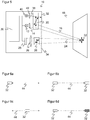
- FIG. 5 shows a schematic representation of a further embodiment of the sensor 10.
- an additional reference light transmitter 40 with optional own collimation optics 42 is provided, which generates the reference light beam 36 in addition to the transmitted light beam 16.
- Transmitting light beam 16 and reference light beam 36 are deflected together and in the same way by the deflection unit 20.
- the entire scanning pattern can thus be tracked in parallel on a spatially resolving active reference target 32.
- only one position or only a few reference positions are monitored with a simpler reference target 32.
- only one deflection can be provided in one direction, ie the sensor 10 can be a line scanner, and accordingly the reference light beam 36 only moves in the line direction.
- the embodiment with an additional reference light transmitter 40 can also be used with the Figures 1 to 4 explained embodiments can be combined as desired.
- a part of the transmitted light beam 16 can also be coupled out as a reference light beam 26, or a part of the beam cross section of the transmitted light beam 16 is used grazingly as a reference light beam 36.
- Figure 6a shows an exemplary arrangement of the reference target 32 at one end of a one-dimensional scanning area 44, which is indicated by an arrow.
- the scanning area 44 corresponds to a line-shaped monitoring area 18.
- the reference target 32 is preferably approached cyclically at the beginning of a line scan, that is to say the scanning begins with a deflection angle pointing somewhat too far to the left for the monitoring area 18.
- Figure 6b shows an exemplary arrangement of reference targets 32 at both ends of a one-dimensional scanning area 44.
- the deflection during regular line scanning is tested somewhat more frequently and in two different positions, so that it can be assumed more reliably that all intermediate positions are also correct.
- the two known edge positions of the reference targets 32 can be used to check or determine the coordinate system of the scanning.
- Figure 6c shows an exemplary arrangement of the reference target 32 within a one-dimensional scanning area 44.
- This reference target 32 covers part of the relevant measuring range, but this may be accepted if, for example, the edge is not available with a narrowly limited possible deflection angle of the deflection unit 20. It is also conceivable that only the parts on the right and left of the reference target 32 are relevant for the measurement, that is to say that separate ROIs are scanned and the reference target 32 is arranged in a gap between them. It is also conceivable that the reference signal of a partially transparent reference target 32, which occurs because of the shortest light path before the measurement signal, is separated in the evaluation or is filtered out, for example, by averaging, so that both the reference angle 32 is both measured and the reference signal is produced.
- Figure 6d shows an exemplary arrangement of reference targets 32 similar Figure 6b , but now the two reference targets 32 generate differently strong reference signals, as indicated by hatching. This can be achieved through different attenuations, blackening, reflectivities, reinforcements and similar effects. Due to the different intensities of the reference signals, more precise tests are possible. More than two reference targets 32 for differently strong reference targets can also be arranged next to and within the scanning area 44.
- FIGS 7a-d show exemplary arrangements of reference targets 32 on different edges of a now two-dimensional scanning area 44.
- the embodiments according to FIG Figure 7a-b With a stripe-shaped reference target 32 on the left and / or right edge are particularly suitable for line-by-line scanning, in which case the addition per line Figure 6a-b applies analogously.
- An order after Figure 7c with a stripe-shaped reference target at the upper and / or lower edge is more suitable for column-wise scanning.
- a reference target 32 running around the edge as in Figure 7d is suitable for line and column scanning and also for variable patterns. In this case, no arrangement of reference targets 32 is necessarily fixed to a specific scanning pattern.
- reference targets 32 are arranged at at least one corner of the scanning area 44. These positions include the other deflection angles, so that their successful examination allows the conclusion of a functioning deflection unit 20 to be particularly reliable.
- Figure 7g shows an exemplary arrangement of reference targets similar Figure 7c on the upper and lower edge of a two-dimensional scanning area, which also generate differently strong reference signals. It is as it were the two-dimensional Analogous to the embodiment Figure 7d with very similar uses and advantages.
- Such reference targets 32 for reference signals of different strengths can be attached at any position, in particular all in the Figures 6a-7i shown positions.
- Figure 7h shows one of these numerous other variants with differently strong reference signals.
- the level of the reference signal varies in opposite directions over two elongated reference targets 32, the continuous course shown being replaceable by discrete reference targets 32 and gradations.
- the specific arrangement with two side strips is also purely exemplary.
- Figure 7i shows another exemplary arrangement of reference targets 32 somewhere within the two-dimensional scanning area 44. Additional reference targets 32 could be added at the edge, and the reference targets 32 could be designed for reference signals of different strengths.
- Figure 6c explained, there is an interaction with the actual measurement when reference targets 32 are arranged within the scanning area 44, but this is accepted, for example, as a kind of dead pixel, which in any case only affects gaps between ROIs or is compensated for by skillful evaluation, an example of a skillful evaluation the too Figure 6c is mentioned temporal separation and another example is immediately explained.
- Figure 7j shows an exemplary arrangement of partially transparent reference targets 32 in a two-dimensional scanning area 44, which form a pattern.
- the pattern forms a kind of watermark.
- the reference signals can possibly be separated from the measurement signals by temporal separation. This is not always possible, for example because the control and evaluation unit 30 is too slow or no longer capable of being aimed, that is to say in particular it does not record the time profile of the received signal at all. Then the fact can be exploited that the pattern of the reference targets 32 is always impressed or superimposed on all received signals. At least in sufficiently dynamic scenarios, for example in the case of mobile applications, the contributions of the object emissions from the monitoring area 18 are distributed very differently, in a simplified manner, at random. If averaging is carried out over several scans, the pattern is recognizable.
Landscapes
- Physics & Mathematics (AREA)
- Engineering & Computer Science (AREA)
- General Physics & Mathematics (AREA)
- Computer Networks & Wireless Communication (AREA)
- Radar, Positioning & Navigation (AREA)
- Remote Sensing (AREA)
- Electromagnetism (AREA)
- Optics & Photonics (AREA)
- Optical Radar Systems And Details Thereof (AREA)
Applications Claiming Priority (1)
| Application Number | Priority Date | Filing Date | Title |
|---|---|---|---|
| DE102018124835.0A DE102018124835B3 (de) | 2018-10-09 | 2018-10-09 | Optoelektronischer Sensor und Verfahren zur Erfassung von Objekten |
Publications (1)
| Publication Number | Publication Date |
|---|---|
| EP3637140A1 true EP3637140A1 (fr) | 2020-04-15 |
Family
ID=67998118
Family Applications (1)
| Application Number | Title | Priority Date | Filing Date |
|---|---|---|---|
| EP19198312.1A Withdrawn EP3637140A1 (fr) | 2018-10-09 | 2019-09-19 | Capteur optoélectronique et procédé de détection des objets |
Country Status (4)
| Country | Link |
|---|---|
| US (1) | US11609422B2 (fr) |
| EP (1) | EP3637140A1 (fr) |
| JP (1) | JP2020064059A (fr) |
| DE (1) | DE102018124835B3 (fr) |
Cited By (1)
| Publication number | Priority date | Publication date | Assignee | Title |
|---|---|---|---|---|
| EP3910373B1 (fr) * | 2020-05-13 | 2022-05-11 | Sick Ag | Lecture des éléments photodiodes d'avalanche en mode geiger |
Families Citing this family (14)
| Publication number | Priority date | Publication date | Assignee | Title |
|---|---|---|---|---|
| JP2023548740A (ja) * | 2020-10-30 | 2023-11-21 | ウェイモ エルエルシー | 垂直共振器面発光レーザ(vcsel)エミッタを有する光検出及び測距(lidar)デバイス |
| DE102020214216A1 (de) * | 2020-11-12 | 2022-05-12 | Robert Bosch Gesellschaft mit beschränkter Haftung | Lidar-Sensor |
| EP4047389B1 (fr) * | 2021-02-18 | 2023-03-29 | Sick Ag | Enregistrement de données d'image tridimensionnelles |
| JP7513549B2 (ja) | 2021-03-08 | 2024-07-09 | 株式会社デンソー | 光学スキャナおよび光学プログラム |
| DE102021107193A1 (de) | 2021-03-23 | 2022-09-29 | Sick Ag | Optische Abstandsmessung mit einem Lichtlaufzeitverfahren |
| DE102021107194A1 (de) | 2021-03-23 | 2022-09-29 | Sick Ag | Optoelektronischer Sensor und Verfahren zur Erfassung von Objekten |
| CN115400247B (zh) * | 2021-05-28 | 2024-02-20 | 宁波方太厨具有限公司 | 一种脉冲消毒器工作监控方法及消毒柜 |
| DE102021117818A1 (de) | 2021-07-09 | 2023-01-12 | Sick Ag | Kamera zur Erfassung dreidimensionaler Bilddaten und Verfahren zur Überprüfung der Funktionsfähigkeit einer Kamera |
| US20210389431A1 (en) * | 2021-08-13 | 2021-12-16 | Intel Corporation | Lidar module and methods thereof |
| CN114200431A (zh) * | 2021-12-10 | 2022-03-18 | 蔚来汽车科技(安徽)有限公司 | 激光雷达点云质量评估方法、系统及装置 |
| JP7097647B1 (ja) * | 2021-12-16 | 2022-07-08 | Dolphin株式会社 | 光走査装置、物体検出装置、光走査装置の調整方法及びプログラム |
| JP7097648B1 (ja) * | 2021-12-16 | 2022-07-08 | Dolphin株式会社 | 光走査装置、物体検出装置、光走査装置の調整方法及びプログラム |
| JP2023133816A (ja) * | 2022-03-14 | 2023-09-27 | ソニーセミコンダクタソリューションズ株式会社 | 測距装置 |
| CN114966609A (zh) * | 2022-04-27 | 2022-08-30 | 蔚来汽车科技(安徽)有限公司 | 激光雷达以及激光雷达检测方法 |
Citations (7)
| Publication number | Priority date | Publication date | Assignee | Title |
|---|---|---|---|---|
| DE4340756A1 (de) | 1992-12-08 | 1994-06-09 | Sick Optik Elektronik Erwin | Laserabstandsermittlungsvorrichtung |
| DE19757849B4 (de) | 1997-12-24 | 2004-12-23 | Sick Ag | Scanner und Vorrichtung zur optischen Erfassung von Hindernissen, sowie deren Verwendung |
| US7972014B2 (en) | 2008-08-05 | 2011-07-05 | Opus Microsystems Corporation | Scanning projection apparatus with phase detection and compensation |
| US20110211243A1 (en) | 2010-03-01 | 2011-09-01 | Gerard Dirk Smits | Safety device for scanned projector and illumination systems |
| EP2708914A1 (fr) | 2012-09-18 | 2014-03-19 | Sick Ag | Capteur optoélectronique et procédé de détection d'une carte de profondeur |
| US20170244955A1 (en) * | 2010-08-11 | 2017-08-24 | Apple Inc. | Scanning projectors and image capture modules for 3D mapping |
| DE102016006776A1 (de) * | 2016-05-25 | 2017-11-30 | Kai Wolf | Vorrichtung und Verfahren zur eindeutigen Abstandsmessung mit moduliertem LIDAR |
Family Cites Families (10)
| Publication number | Priority date | Publication date | Assignee | Title |
|---|---|---|---|---|
| DE19647152A1 (de) * | 1996-11-14 | 1998-05-28 | Sick Ag | Laserabstandsermittlungsvorrichtung |
| JP2002090681A (ja) | 2000-09-14 | 2002-03-27 | Minolta Co Ltd | 光学走査装置および3次元測定装置 |
| JP4953502B2 (ja) * | 2000-10-02 | 2012-06-13 | 日本信号株式会社 | 2次元走査型光レーダセンサ |
| JP2004157044A (ja) | 2002-11-07 | 2004-06-03 | Nippon Signal Co Ltd:The | 走査型レーザレーダ |
| JP2005077288A (ja) | 2003-09-01 | 2005-03-24 | Nissan Motor Co Ltd | レーダ装置 |
| DE102011113147B3 (de) * | 2011-09-14 | 2013-01-17 | Fraunhofer-Gesellschaft zur Förderung der angewandten Forschung e.V. | Vorrichtung zur optischen Abstandsmessung |
| JP5932371B2 (ja) | 2012-02-02 | 2016-06-08 | 三菱電機株式会社 | 形状測定装置 |
| JP6616077B2 (ja) | 2015-02-16 | 2019-12-04 | 株式会社トプコン | 測定装置及び3次元カメラ |
| EP4220230A1 (fr) * | 2017-09-26 | 2023-08-02 | Innoviz Technologies Ltd. | Systèmes et procédés lidar |
| WO2019149815A1 (fr) * | 2018-02-02 | 2019-08-08 | Uab Brolis Semiconductors | Détermination de longueur d'onde pour lasers largement accordables et systèmes laser associés |
-
2018
- 2018-10-09 DE DE102018124835.0A patent/DE102018124835B3/de active Active
-
2019
- 2019-09-19 EP EP19198312.1A patent/EP3637140A1/fr not_active Withdrawn
- 2019-10-07 JP JP2019184500A patent/JP2020064059A/ja active Pending
- 2019-10-07 US US16/594,638 patent/US11609422B2/en active Active
Patent Citations (7)
| Publication number | Priority date | Publication date | Assignee | Title |
|---|---|---|---|---|
| DE4340756A1 (de) | 1992-12-08 | 1994-06-09 | Sick Optik Elektronik Erwin | Laserabstandsermittlungsvorrichtung |
| DE19757849B4 (de) | 1997-12-24 | 2004-12-23 | Sick Ag | Scanner und Vorrichtung zur optischen Erfassung von Hindernissen, sowie deren Verwendung |
| US7972014B2 (en) | 2008-08-05 | 2011-07-05 | Opus Microsystems Corporation | Scanning projection apparatus with phase detection and compensation |
| US20110211243A1 (en) | 2010-03-01 | 2011-09-01 | Gerard Dirk Smits | Safety device for scanned projector and illumination systems |
| US20170244955A1 (en) * | 2010-08-11 | 2017-08-24 | Apple Inc. | Scanning projectors and image capture modules for 3D mapping |
| EP2708914A1 (fr) | 2012-09-18 | 2014-03-19 | Sick Ag | Capteur optoélectronique et procédé de détection d'une carte de profondeur |
| DE102016006776A1 (de) * | 2016-05-25 | 2017-11-30 | Kai Wolf | Vorrichtung und Verfahren zur eindeutigen Abstandsmessung mit moduliertem LIDAR |
Cited By (1)
| Publication number | Priority date | Publication date | Assignee | Title |
|---|---|---|---|---|
| EP3910373B1 (fr) * | 2020-05-13 | 2022-05-11 | Sick Ag | Lecture des éléments photodiodes d'avalanche en mode geiger |
Also Published As
| Publication number | Publication date |
|---|---|
| US11609422B2 (en) | 2023-03-21 |
| JP2020064059A (ja) | 2020-04-23 |
| US20200110259A1 (en) | 2020-04-09 |
| DE102018124835B3 (de) | 2019-11-07 |
Similar Documents
| Publication | Publication Date | Title |
|---|---|---|
| DE102018124835B3 (de) | Optoelektronischer Sensor und Verfahren zur Erfassung von Objekten | |
| EP3557284A2 (fr) | Capteur optoélectronique et procédé de détermination de la distance | |
| DE102007008806C5 (de) | Optoelektronische Überwachung mit Test durch Dynamisierung | |
| EP1355128B1 (fr) | Alignement automatique d'un senseur | |
| EP3279685B2 (fr) | Capteur optoélectronique et procédé de détection d'un objet | |
| DE102018108340A1 (de) | Optoelektronischer Sensor und Verfahren zur Erfassung und Abstandsbestimmung von Objekten | |
| EP3355076A1 (fr) | Capteur optoélectronique et procédé de détection de l'élimination d'un objet dans une zone de surveillance | |
| EP2708914A1 (fr) | Capteur optoélectronique et procédé de détection d'une carte de profondeur | |
| EP2202533A1 (fr) | Dispositif de détection | |
| EP3168641A1 (fr) | Procede et dispositif de mesure de distance optique | |
| DE102017002235A1 (de) | LIDAR-System mit flexiblen Scanparametern | |
| EP3581958A1 (fr) | Capteur optoélectronique et procédé de détection des données d'image tridimensionnelles | |
| EP2708913A1 (fr) | Capteur optoélectronique et procédé de détection d'objet | |
| DE112011102535T5 (de) | Abtastenden Bildgeber mit aktiver Beleuchtung | |
| EP2927711A1 (fr) | Lecteur laser et procédé de saisie sécurisée d'objets | |
| EP2296002A1 (fr) | Scanner optoélectronique pour la détermination de distances en azimut et élévation | |
| DE102009047303A1 (de) | Einrichtung für die Kalibrierung eines Sensors | |
| DE102014118149A1 (de) | Optoelektronischer Sensor und Verfahren zum Erfassen von Objekten | |
| EP3809157B1 (fr) | Capteur optoélectronique de mesure de distance et procédé de détection d'un objet cible | |
| DE102018214140A1 (de) | LIDAR-Sensor zur optischen Erfassung eines Sichtfeldes, Arbeitsvorrichtung oder Fahrzeug mit einem LIDAR-Sensor und Verfahren zur optischen Erfassung eines Sichtfeldes | |
| DE102019125684B4 (de) | Optoelektronischer Sensor und Verfahren zur Erfassung von Objekten | |
| EP4063902A1 (fr) | Capteur optoélectronique et procédé de détection d'objets | |
| DE102018125591B4 (de) | Optisches Abstandsermittlungsmodul | |
| EP2851704B1 (fr) | Dispositif et procédé de détermination optique de distances par rapport à des objets dans une zone de surveillance | |
| DE202011052106U1 (de) | Entfernungsmessender optoelektronischer Sensor |
Legal Events
| Date | Code | Title | Description |
|---|---|---|---|
| PUAI | Public reference made under article 153(3) epc to a published international application that has entered the european phase |
Free format text: ORIGINAL CODE: 0009012 |
|
| STAA | Information on the status of an ep patent application or granted ep patent |
Free format text: STATUS: THE APPLICATION HAS BEEN PUBLISHED |
|
| AK | Designated contracting states |
Kind code of ref document: A1 Designated state(s): AL AT BE BG CH CY CZ DE DK EE ES FI FR GB GR HR HU IE IS IT LI LT LU LV MC MK MT NL NO PL PT RO RS SE SI SK SM TR |
|
| AX | Request for extension of the european patent |
Extension state: BA ME |
|
| 18D | Application deemed to be withdrawn |
Effective date: 20201016 |