EP3637093A1 - Automated defect detection for wire rope using image processing techniques - Google Patents
Automated defect detection for wire rope using image processing techniques Download PDFInfo
- Publication number
- EP3637093A1 EP3637093A1 EP19202237.4A EP19202237A EP3637093A1 EP 3637093 A1 EP3637093 A1 EP 3637093A1 EP 19202237 A EP19202237 A EP 19202237A EP 3637093 A1 EP3637093 A1 EP 3637093A1
- Authority
- EP
- European Patent Office
- Prior art keywords
- defect
- flexible member
- rope
- image data
- sensors
- Prior art date
- Legal status (The legal status is an assumption and is not a legal conclusion. Google has not performed a legal analysis and makes no representation as to the accuracy of the status listed.)
- Granted
Links
Images


Classifications
-
- G—PHYSICS
- G01—MEASURING; TESTING
- G01N—INVESTIGATING OR ANALYSING MATERIALS BY DETERMINING THEIR CHEMICAL OR PHYSICAL PROPERTIES
- G01N21/00—Investigating or analysing materials by the use of optical means, i.e. using sub-millimetre waves, infrared, visible or ultraviolet light
- G01N21/84—Systems specially adapted for particular applications
- G01N21/88—Investigating the presence of flaws or contamination
- G01N21/95—Investigating the presence of flaws or contamination characterised by the material or shape of the object to be examined
- G01N21/952—Inspecting the exterior surface of cylindrical bodies or wires
-
- B—PERFORMING OPERATIONS; TRANSPORTING
- B66—HOISTING; LIFTING; HAULING
- B66B—ELEVATORS; ESCALATORS OR MOVING WALKWAYS
- B66B7/00—Other common features of elevators
- B66B7/12—Checking, lubricating, or cleaning means for ropes, cables or guides
- B66B7/1207—Checking means
- B66B7/1215—Checking means specially adapted for ropes or cables
- B66B7/1238—Checking means specially adapted for ropes or cables by optical techniques
-
- G—PHYSICS
- G01—MEASURING; TESTING
- G01N—INVESTIGATING OR ANALYSING MATERIALS BY DETERMINING THEIR CHEMICAL OR PHYSICAL PROPERTIES
- G01N21/00—Investigating or analysing materials by the use of optical means, i.e. using sub-millimetre waves, infrared, visible or ultraviolet light
- G01N21/84—Systems specially adapted for particular applications
- G01N21/88—Investigating the presence of flaws or contamination
- G01N21/8851—Scan or image signal processing specially adapted therefor, e.g. for scan signal adjustment, for detecting different kinds of defects, for compensating for structures, markings, edges
-
- G—PHYSICS
- G01—MEASURING; TESTING
- G01N—INVESTIGATING OR ANALYSING MATERIALS BY DETERMINING THEIR CHEMICAL OR PHYSICAL PROPERTIES
- G01N21/00—Investigating or analysing materials by the use of optical means, i.e. using sub-millimetre waves, infrared, visible or ultraviolet light
- G01N21/84—Systems specially adapted for particular applications
- G01N21/88—Investigating the presence of flaws or contamination
- G01N21/95—Investigating the presence of flaws or contamination characterised by the material or shape of the object to be examined
-
- G—PHYSICS
- G01—MEASURING; TESTING
- G01N—INVESTIGATING OR ANALYSING MATERIALS BY DETERMINING THEIR CHEMICAL OR PHYSICAL PROPERTIES
- G01N23/00—Investigating or analysing materials by the use of wave or particle radiation, e.g. X-rays or neutrons, not covered by groups G01N3/00 – G01N17/00, G01N21/00 or G01N22/00
- G01N23/20—Investigating or analysing materials by the use of wave or particle radiation, e.g. X-rays or neutrons, not covered by groups G01N3/00 – G01N17/00, G01N21/00 or G01N22/00 by using diffraction of the radiation by the materials, e.g. for investigating crystal structure; by using scattering of the radiation by the materials, e.g. for investigating non-crystalline materials; by using reflection of the radiation by the materials
- G01N23/207—Diffractometry using detectors, e.g. using a probe in a central position and one or more displaceable detectors in circumferential positions
-
- G—PHYSICS
- G06—COMPUTING OR CALCULATING; COUNTING
- G06T—IMAGE DATA PROCESSING OR GENERATION, IN GENERAL
- G06T7/00—Image analysis
- G06T7/0002—Inspection of images, e.g. flaw detection
-
- G—PHYSICS
- G06—COMPUTING OR CALCULATING; COUNTING
- G06T—IMAGE DATA PROCESSING OR GENERATION, IN GENERAL
- G06T7/00—Image analysis
- G06T7/0002—Inspection of images, e.g. flaw detection
- G06T7/0004—Industrial image inspection
- G06T7/001—Industrial image inspection using an image reference approach
-
- D—TEXTILES; PAPER
- D07—ROPES; CABLES OTHER THAN ELECTRIC
- D07B—ROPES OR CABLES IN GENERAL
- D07B1/00—Constructional features of ropes or cables
- D07B1/14—Ropes or cables with incorporated auxiliary elements, e.g. for marking, extending throughout the length of the rope or cable
- D07B1/145—Ropes or cables with incorporated auxiliary elements, e.g. for marking, extending throughout the length of the rope or cable comprising elements for indicating or detecting the rope or cable status
-
- D—TEXTILES; PAPER
- D07—ROPES; CABLES OTHER THAN ELECTRIC
- D07B—ROPES OR CABLES IN GENERAL
- D07B2301/00—Controls
- D07B2301/55—Sensors
- D07B2301/5531—Sensors using electric means or elements
- D07B2301/5577—Sensors using electric means or elements using light guides
-
- G—PHYSICS
- G01—MEASURING; TESTING
- G01N—INVESTIGATING OR ANALYSING MATERIALS BY DETERMINING THEIR CHEMICAL OR PHYSICAL PROPERTIES
- G01N21/00—Investigating or analysing materials by the use of optical means, i.e. using sub-millimetre waves, infrared, visible or ultraviolet light
- G01N21/84—Systems specially adapted for particular applications
- G01N21/88—Investigating the presence of flaws or contamination
- G01N21/8851—Scan or image signal processing specially adapted therefor, e.g. for scan signal adjustment, for detecting different kinds of defects, for compensating for structures, markings, edges
- G01N2021/8854—Grading and classifying of flaws
-
- G—PHYSICS
- G01—MEASURING; TESTING
- G01N—INVESTIGATING OR ANALYSING MATERIALS BY DETERMINING THEIR CHEMICAL OR PHYSICAL PROPERTIES
- G01N21/00—Investigating or analysing materials by the use of optical means, i.e. using sub-millimetre waves, infrared, visible or ultraviolet light
- G01N21/84—Systems specially adapted for particular applications
- G01N21/88—Investigating the presence of flaws or contamination
- G01N21/8851—Scan or image signal processing specially adapted therefor, e.g. for scan signal adjustment, for detecting different kinds of defects, for compensating for structures, markings, edges
- G01N2021/8854—Grading and classifying of flaws
- G01N2021/8858—Flaw counting
-
- G—PHYSICS
- G01—MEASURING; TESTING
- G01N—INVESTIGATING OR ANALYSING MATERIALS BY DETERMINING THEIR CHEMICAL OR PHYSICAL PROPERTIES
- G01N21/00—Investigating or analysing materials by the use of optical means, i.e. using sub-millimetre waves, infrared, visible or ultraviolet light
- G01N21/84—Systems specially adapted for particular applications
- G01N21/88—Investigating the presence of flaws or contamination
- G01N21/8851—Scan or image signal processing specially adapted therefor, e.g. for scan signal adjustment, for detecting different kinds of defects, for compensating for structures, markings, edges
- G01N2021/8887—Scan or image signal processing specially adapted therefor, e.g. for scan signal adjustment, for detecting different kinds of defects, for compensating for structures, markings, edges based on image processing techniques
-
- G—PHYSICS
- G01—MEASURING; TESTING
- G01N—INVESTIGATING OR ANALYSING MATERIALS BY DETERMINING THEIR CHEMICAL OR PHYSICAL PROPERTIES
- G01N2201/00—Features of devices classified in G01N21/00
- G01N2201/06—Illumination; Optics
- G01N2201/068—Optics, miscellaneous
-
- G—PHYSICS
- G01—MEASURING; TESTING
- G01N—INVESTIGATING OR ANALYSING MATERIALS BY DETERMINING THEIR CHEMICAL OR PHYSICAL PROPERTIES
- G01N2201/00—Features of devices classified in G01N21/00
- G01N2201/08—Optical fibres; light guides
- G01N2201/088—Using a sensor fibre
-
- G—PHYSICS
- G06—COMPUTING OR CALCULATING; COUNTING
- G06T—IMAGE DATA PROCESSING OR GENERATION, IN GENERAL
- G06T2207/00—Indexing scheme for image analysis or image enhancement
- G06T2207/30—Subject of image; Context of image processing
- G06T2207/30108—Industrial image inspection
- G06T2207/30136—Metal
Definitions
- the embodiments described herein generally relate to health monitoring and more particularly to performing automated defect detection for a wire rope using image processing techniques.
- Cables and wire ropes are used across all types of industries and applications. For example, cables are used in elevators, hoists, cranes, etc. These applications include safety-critical applications such as human carrying rescue missions. These cables are required to undergo periodic inspections to determine if any defects exist. There are various types of defects that may occur for example, broken wires, broken strands, etc. due to fatigue, heaving loading, or other events. There may be a need to consistently and efficiently perform cable inspections.
- a system for performing automated defect detection for a flexible member using image processing includes one or more sensors configured to monitor a flexible member, an image processor configured to convert the sensor data from the one or more sensors to image data, and a processing module configured to receive reference image data.
- the processing module is also configured to compare the image data with the reference image data, determine a defect based on the comparison and a threshold setting information for the flexible member, and transmit a notification based on the defect.
- further embodiments include a processing module that is configured to determine the defect further comprises categorizing the defect into one or more classes based at least in part on the defect.
- further embodiments include one or more sensors that are optical fibers.
- further embodiments include a flexible member that is at least one of rope, wire, belt, and chain.
- further embodiments include using reference image data that is based on the flexible member.
- further embodiments include threshold setting information that is based on an application type for the flexible member.
- further embodiments include a processing module that is configured to determine a location of the defect of the flexible member.
- further embodiments include a notification that includes a location of the defect, a number of defects, a type of defect, or a recommendation for performing a service relating to the flexible member.
- a method for performing automated defect detection for a flexible member using image processing includes monitoring, by one or more sensors, a flexible member to obtain sensor data, converting the sensor data from the one or more sensors to image data, and receiving reference image data to compare to the image data.
- the method also includes determining a defect based on the comparison and threshold setting information for the flexible member, and transmitting a notification based on the defect.
- further embodiments include determining the defect further by categorizing the defect into one or more classes based at least in part on the defect.
- further embodiments include one or more sensors that are optical fibers.
- further embodiments include a flexible member that is at least one of rope, wire, belt, and chain.
- further embodiments include reference image data that is based on the flexible member.
- further embodiments include using threshold setting information that is based on an application type for the flexible member.
- further embodiments include determining a location of the defect of the flexible member.
- notification including a location of the defect, a number of defects, a type of defect, or a recommendation for performing a service relating to the flexible member.
- inventions of the present disclosure include utilizing optical fibers, lens and image sensor and image processors to consistently and efficiently monitor the health of cables and wire ropes.
- ropes In today's environment ropes, cables, and wires (generally referred to as ropes) are used for various applications.
- the application the ropes are used for can determine the frequency at which they are to be inspected and the tolerances allowed for the ropes for replacement/repair. Frequent inspections may be required for safety-critical application such as every 100 cycles or 10 hours of operation, where non-safety-critical applications can be inspected at longer intervals.
- Ropes are flexible members and can be subjected to sudden loads and external disturbances, where the loading of the rope exceeds the rated load of the rope.
- the ropes can be subjected to repeated loads that can eventually lead to defects. These defects can include kinking, bird-caging (strand issue caused by metal-metal contact), dirt, corrosion, and a host of other factors.
- the ropes are inspected by trained technicians and the health of the rope can vary based on the manual inspection by different service technicians. The service technician's skill and experience can inform their assessment of the rope's health which can lead to a range of subjectivity for the same rope and/or defect.
- the rope inspection cannot occur during the operation. Therefore, the device including the rope and/or flexible member may suffer downtime due to the time it takes to remove the rope and send it off for inspection.
- the length of the rope can vary based on their application. For example, ropes that are being used for elevator applications can range in length adding additional time to the inspection procedure. Also, different types of ropes exist which can exhibit different types of defects and the service technician must be knowledgeable of each type of rope, their tolerances, and associated defects.
- the techniques described herein provide for a non-intrusive based diagnostic method for rope health monitoring by using image processing techniques. In addition, the techniques provide for a prognostic analysis of the rope or other flexible member.
- the techniques described herein can use one or more sensors to collect data for the rope and monitor the health of a rope where the sensors can include fiber optic sensors.
- the techniques described herein also provide for defect detection by using an image processing and analysis method. Multiple algorithms can be used to analyze the rope for defects and the algorithms can be selected to best suit the application.
- One or more techniques include a defect detection method that classifies the type of failure and also ranks severity for operational clearance based on the application of the rope. For example, safety-critical applications such as rescue missions may require tighter threshold tolerances than non-safety critical applications.
- the techniques described herein also provide for consistent defect detection in a rope or other flexible member be determining the number of defects, types of defects, the location of defects in the rope, and other information related to the rope.
- the system can be updated based on the collected field failure data to improve the overall detection efficiency and correlating the defects for the different types of rope to the rope health.
- FIG. 1 a system 100 for performing automated defect detection method for a rope using image processing in accordance with one or more embodiments is provided.
- the system 100 includes an image capture device 102 which is located within the control electronics of the wire rope handling device 130.
- the wire rope handling device 130 includes a mount 104 and configured to monitor a flexible member 106 such as a rope, belt, wire, etc.
- the mount 104 can be positioned near a location where the flexible member 106 is dispensed from a device that controls it.
- the image capture device 102 includes one or more sensors such as optical fibers that are configured to detect sensor data from the flexible member 106 by providing a light on the surface of the flexible member 106 and analyzing the light that is reflected off of the surface of the flexible member 106.
- the sensors are positioned to detect the entire surface of the flexible member 106.
- the system 100 also includes an image conversion system 108 that is configured to receive the sensor data from the image capture device 102 and convert the sensor data to image data.
- the sensor data is optical light data and the light information is converted to form an image of the flexible member 106.
- FIG. 1 also depicts an image processor 110, where the image processor 110 is configured to enhance the image data from the conversion system 108 for further processing.
- the image processor 110 is configured to increase the sharpness of the image data, remove blurring, removing distortion, crop the image to a region of interest, monochrome image, etc. to proper the image for further processing and analysis for defect detection.
- the processing module 110 is configured to execute a variety of algorithms for processing the image data received from the image processor 110.
- the processing module 110 is also configured to receive reference image data from a reference image data source 114 and threshold setting information from a threshold setting source 116.
- the reference image data and the threshold settings information corresponding to the type of flexible member 106 that is being monitored by the system 100 which is used to compare the current flexible member 106 to a healthy or new flexible member.
- the reference image information can include information such as rope type, length, diameter, strand information, the pattern of rope/strands, etc.
- the threshold setting information can include information such as defect types, defect classes that are mapped to the remaining life or strength of the rope.
- the processing module 112 can transmit the results to a display 118.
- a display 118 can be included in the system 100 to display the results of the analysis.
- the display 118 can present graphical data, textual data, visual image of the rope, etc.
- the display 118 can also present notification information for an operator that indicates information such as the health of the rope including the severity of any defects that exist or a recommendation as to when the rope should be repaired/replaced.
- an alert can be transmitted to an operator or other user through the alert module 120.
- the alerts can include information related to the type of defect, the severity of defects of the rope, number of defects, a recommendation as to repair and/or replacement, estimated time for repair, visual of defects, etc.
- the results of the analysis performed by the system 100 can be stored in a storage device 122. Machine-learning can optimize the types of defects and the remaining life of the rope and recommendations provided for a defect of the rope.
- FIG. 2 a view of an arrangement 200 of the mount 104 used in the system 100 in accordance with one or more embodiments is shown.
- the device 102 includes a mount 104 that is configured to house one or more sensors such as the optical fibers for monitoring the flexible member 106.
- Each optical fiber includes an optical fiber port 202A, B, and C as shown in FIG. 3 .
- Each optical fiber port 202 is configured to transmit and receive optical signals L1, L2, and L3 and has a field of view 204 as shown in FIG. 2 .
- the optical fibers and ports 202 are spaced apart at 120 degrees to cover the entire surface of the rope 106.
- a different number of sensors, sensor types, spacing, etc. can be used to monitoring the health of the rope.
- one or two sensor devices can be used to monitor the rope.
- the optical port 202 is configured to be attached to the housing/mount 104 shown in FIG. 2 .
- the optical port 202 receives the optical cable 302 that is configured to exchange optical signal data to the image processor 110 shown in FIG. 1 .
- the optical port 202 also includes one or more filters 304 and lenses 306.
- the optical port 202 includes a light source 308 that is configured to transmit a light to the rope 106 and the optical port 202 is configured to receive the reflected light data that characterize the surface of the rope 106 for further processes.
- a processing flow 400 for processing the image data in accordance with one or more embodiments is shown.
- the inputs received at block 402 include the set of data 404 including the captured image data, image file name, the location of the rope segment, and reference image data.
- the system 100 is configured to receive rope segment information from the hoist or rope dispensing system indicates a location of the length of rope that has been dispensed. This information can include the size and number of turns of a drum that is used to dispense the rope. It should be understood that other techniques that can be used. It should be understood that other data can be received and used in the processing of image data.
- image data is converted to black and white for further processing.
- a first marking technique 408A utilizes a Canny transform that is used to compare the edges of the rope to the reference image. For example, loose strand information can be obtained using the Canny transform processing.
- a second marking technique 408B includes a differentiation filter for image gradient/image Laplacian magnitude which is used to compare the current image to the reference image. Each frame can monitor a certain length of the rope and splits the frame into smaller frames/windows for analysis against the reference frame.
- a third marking technique 408C includes using block-based pixel color analysis to each segment of the rope. During processing, the image of the current rope can be provided as a matrix that is compared to the reference image that is also provided as a matrix.
- the two matrices can be compared to each other further compared to the tolerances that are allowed by the threshold settings for that particular rope.
- a voting for a defect image of the various marking methods is performed.
- the marking technique compares the reference image with the actual (defect) image.
- the voting process allows for a threshold tolerance for various applications to be used to determine whether the rope is fit for operations or requires repair/replacement. It should be understood that the selection can be selected according to a configurable selection.
- the resulting defect image 412 can be provided to the operator in a notification and/or further analysis.
- the method 500 begins at block 502 and proceeds to block 504 which provides for monitoring, by one or more sensors, a flexible member to obtain sensor data.
- the method 500 continues to block 506 and provides for converting the sensor data from the one or more sensors to image data.
- Block 508 provides for receiving reference image data and threshold setting information.
- the method 500 provides for comparing the image data with the reference image data.
- Block 512 provides for determining a defect based on the comparison and the threshold setting information.
- the method at block 514 provides for transmitting a notification based on the defect.
- the method 500 ends at block 516.
- the technical effects and benefits include real-time rope health monitoring providing prognostic and diagnostic solutions. Therefore there is an increased reliability of the system due to onboard diagnostics.
- the technical effect and benefits include a reduced time for manual inspections and increased consistency in reporting rope health. There is also an increase in personnel safety when using wire ropes used for human and cargo applications.
- the system can be made more intelligent with machine learning techniques that are used to analyze the field service data to accurately identify defects and correlate the defects to the remaining life of the rope.
Landscapes
- General Physics & Mathematics (AREA)
- Physics & Mathematics (AREA)
- Engineering & Computer Science (AREA)
- Chemical & Material Sciences (AREA)
- Immunology (AREA)
- Biochemistry (AREA)
- General Health & Medical Sciences (AREA)
- Analytical Chemistry (AREA)
- Life Sciences & Earth Sciences (AREA)
- Pathology (AREA)
- Health & Medical Sciences (AREA)
- Computer Vision & Pattern Recognition (AREA)
- Quality & Reliability (AREA)
- Theoretical Computer Science (AREA)
- Signal Processing (AREA)
- Crystallography & Structural Chemistry (AREA)
- Investigating Materials By The Use Of Optical Means Adapted For Particular Applications (AREA)
Abstract
Description
- This application claims the benefit of Indian Application No.
201811038485 filed October 10, 2018 - The embodiments described herein generally relate to health monitoring and more particularly to performing automated defect detection for a wire rope using image processing techniques.
- Cables and wire ropes are used across all types of industries and applications. For example, cables are used in elevators, hoists, cranes, etc. These applications include safety-critical applications such as human carrying rescue missions. These cables are required to undergo periodic inspections to determine if any defects exist. There are various types of defects that may occur for example, broken wires, broken strands, etc. due to fatigue, heaving loading, or other events. There may be a need to consistently and efficiently perform cable inspections.
- According to an embodiment, a system for performing automated defect detection for a flexible member using image processing is provided the system includes one or more sensors configured to monitor a flexible member, an image processor configured to convert the sensor data from the one or more sensors to image data, and a processing module configured to receive reference image data. The processing module is also configured to compare the image data with the reference image data, determine a defect based on the comparison and a threshold setting information for the flexible member, and transmit a notification based on the defect.
- In addition to one or more of the features described herein, or as an alternative, further embodiments include a processing module that is configured to determine the defect further comprises categorizing the defect into one or more classes based at least in part on the defect.
- In addition to one or more of the features described herein, or as an alternative, further embodiments include one or more sensors that are optical fibers.
- In addition to one or more of the features described herein, or as an alternative, further embodiments include a flexible member that is at least one of rope, wire, belt, and chain.
- In addition to one or more of the features described herein, or as an alternative, further embodiments include using reference image data that is based on the flexible member.
- In addition to one or more of the features described herein, or as an alternative, further embodiments include threshold setting information that is based on an application type for the flexible member.
- In addition to one or more of the features described herein, or as an alternative, further embodiments include a processing module that is configured to determine a location of the defect of the flexible member.
- In addition to one or more of the features described herein, or as an alternative, further embodiments include a notification that includes a location of the defect, a number of defects, a type of defect, or a recommendation for performing a service relating to the flexible member.
- According to another embodiment, a method for performing automated defect detection for a flexible member using image processing is provided. The method includes monitoring, by one or more sensors, a flexible member to obtain sensor data, converting the sensor data from the one or more sensors to image data, and receiving reference image data to compare to the image data. The method also includes determining a defect based on the comparison and threshold setting information for the flexible member, and transmitting a notification based on the defect.
- In addition to one or more of the features described herein, or as an alternative, further embodiments include determining the defect further by categorizing the defect into one or more classes based at least in part on the defect.
- In addition to one or more of the features described herein, or as an alternative, further embodiments include one or more sensors that are optical fibers.
- In addition to one or more of the features described herein, or as an alternative, further embodiments include a flexible member that is at least one of rope, wire, belt, and chain.
- In addition to one or more of the features described herein, or as an alternative, further embodiments include reference image data that is based on the flexible member.
- In addition to one or more of the features described herein, or as an alternative, further embodiments include using threshold setting information that is based on an application type for the flexible member.
- In addition to one or more of the features described herein, or as an alternative, further embodiments include determining a location of the defect of the flexible member.
- In addition to one or more of the features described herein, or as an alternative, further embodiments include notification including a location of the defect, a number of defects, a type of defect, or a recommendation for performing a service relating to the flexible member.
- Technical effects of embodiments of the present disclosure include utilizing optical fibers, lens and image sensor and image processors to consistently and efficiently monitor the health of cables and wire ropes.
- The foregoing features and elements may be combined in various combinations without exclusivity, unless expressly indicated otherwise. These features and elements as well as the operation thereof will become more apparent in light of the following description and the accompanying drawings. It should be understood, however, that the following description and drawings are intended to be illustrative and explanatory in nature and non-limiting.
- The following descriptions should not be considered limiting in any way. With reference to the accompanying drawings, like elements are numbered alike:
-
FIG. 1 depicts a system for performing automated defect detection for a wire rope using image processing techniques in accordance with one or more embodiments; -
FIG. 2 depicts an arrangement of the system in accordance with one or more embodiments; -
FIG. 3 depicts an arrangement of an optical port in accordance with one or more embodiments; -
FIG. 4 depicts a process flow for performing automated defect detection for a wire rope using image processing in accordance with one or more embodiments; and -
FIG. 5 depicts a flowchart for a method for performing automated defect detection for a wire rope using image processing techniques in accordance with one or more embodiments. - In today's environment ropes, cables, and wires (generally referred to as ropes) are used for various applications. The application the ropes are used for, can determine the frequency at which they are to be inspected and the tolerances allowed for the ropes for replacement/repair. Frequent inspections may be required for safety-critical application such as every 100 cycles or 10 hours of operation, where non-safety-critical applications can be inspected at longer intervals.
- Ropes are flexible members and can be subjected to sudden loads and external disturbances, where the loading of the rope exceeds the rated load of the rope. In addition, the ropes can be subjected to repeated loads that can eventually lead to defects. These defects can include kinking, bird-caging (strand issue caused by metal-metal contact), dirt, corrosion, and a host of other factors. The ropes are inspected by trained technicians and the health of the rope can vary based on the manual inspection by different service technicians. The service technician's skill and experience can inform their assessment of the rope's health which can lead to a range of subjectivity for the same rope and/or defect.
- In addition, the rope inspection cannot occur during the operation. Therefore, the device including the rope and/or flexible member may suffer downtime due to the time it takes to remove the rope and send it off for inspection. The length of the rope can vary based on their application. For example, ropes that are being used for elevator applications can range in length adding additional time to the inspection procedure. Also, different types of ropes exist which can exhibit different types of defects and the service technician must be knowledgeable of each type of rope, their tolerances, and associated defects.
- The techniques described herein provide for a non-intrusive based diagnostic method for rope health monitoring by using image processing techniques. In addition, the techniques provide for a prognostic analysis of the rope or other flexible member. The techniques described herein can use one or more sensors to collect data for the rope and monitor the health of a rope where the sensors can include fiber optic sensors.
- The techniques described herein also provide for defect detection by using an image processing and analysis method. Multiple algorithms can be used to analyze the rope for defects and the algorithms can be selected to best suit the application. One or more techniques include a defect detection method that classifies the type of failure and also ranks severity for operational clearance based on the application of the rope. For example, safety-critical applications such as rescue missions may require tighter threshold tolerances than non-safety critical applications.
- The techniques described herein also provide for consistent defect detection in a rope or other flexible member be determining the number of defects, types of defects, the location of defects in the rope, and other information related to the rope. In one or more embodiments, the system can be updated based on the collected field failure data to improve the overall detection efficiency and correlating the defects for the different types of rope to the rope health.
- In
FIG. 1 , asystem 100 for performing automated defect detection method for a rope using image processing in accordance with one or more embodiments is provided. - The
system 100 includes animage capture device 102 which is located within the control electronics of the wirerope handling device 130. The wirerope handling device 130 includes amount 104 and configured to monitor aflexible member 106 such as a rope, belt, wire, etc. Themount 104 can be positioned near a location where theflexible member 106 is dispensed from a device that controls it. In one or more embodiments, theimage capture device 102 includes one or more sensors such as optical fibers that are configured to detect sensor data from theflexible member 106 by providing a light on the surface of theflexible member 106 and analyzing the light that is reflected off of the surface of theflexible member 106. The sensors are positioned to detect the entire surface of theflexible member 106. In this non-limiting example, there are three optical fibers (L1, L2, and L3) that are used to detect the sensor data from the flexible member. - The
system 100 also includes animage conversion system 108 that is configured to receive the sensor data from theimage capture device 102 and convert the sensor data to image data. In a non-limiting example, the sensor data is optical light data and the light information is converted to form an image of theflexible member 106.FIG. 1 also depicts animage processor 110, where theimage processor 110 is configured to enhance the image data from theconversion system 108 for further processing. Theimage processor 110 is configured to increase the sharpness of the image data, remove blurring, removing distortion, crop the image to a region of interest, monochrome image, etc. to proper the image for further processing and analysis for defect detection. - The
processing module 110 is configured to execute a variety of algorithms for processing the image data received from theimage processor 110. Theprocessing module 110 is also configured to receive reference image data from a referenceimage data source 114 and threshold setting information from athreshold setting source 116. The reference image data and the threshold settings information corresponding to the type offlexible member 106 that is being monitored by thesystem 100 which is used to compare the currentflexible member 106 to a healthy or new flexible member. The reference image information can include information such as rope type, length, diameter, strand information, the pattern of rope/strands, etc. The threshold setting information can include information such as defect types, defect classes that are mapped to the remaining life or strength of the rope. It should be understood that other types of information can be included in the reference image and threshold setting information and the information can vary for each type of rope, as well as the application the rope is being used for. For example, the same rope that is used for two different applications can have different acceptable tolerances and threshold for operations. - Responsive to performing the processing and analysis of the current image of the
flexible member 106 with the reference image and the threshold setting information, theprocessing module 112 can transmit the results to adisplay 118. - In one or more embodiments, a
display 118 can be included in thesystem 100 to display the results of the analysis. Thedisplay 118 can present graphical data, textual data, visual image of the rope, etc. Thedisplay 118 can also present notification information for an operator that indicates information such as the health of the rope including the severity of any defects that exist or a recommendation as to when the rope should be repaired/replaced. - Responsive to the results of the analysis, an alert can be transmitted to an operator or other user through the
alert module 120. The alerts can include information related to the type of defect, the severity of defects of the rope, number of defects, a recommendation as to repair and/or replacement, estimated time for repair, visual of defects, etc. The results of the analysis performed by thesystem 100 can be stored in astorage device 122. Machine-learning can optimize the types of defects and the remaining life of the rope and recommendations provided for a defect of the rope. - In
FIG. 2 , a view of anarrangement 200 of themount 104 used in thesystem 100 in accordance with one or more embodiments is shown. Thedevice 102 includes amount 104 that is configured to house one or more sensors such as the optical fibers for monitoring theflexible member 106. Each optical fiber includes anoptical fiber port 202A, B, and C as shown inFIG. 3 . Eachoptical fiber port 202 is configured to transmit and receive optical signals L1, L2, and L3 and has a field ofview 204 as shown inFIG. 2 . - In one or more embodiments, the optical fibers and
ports 202 are spaced apart at 120 degrees to cover the entire surface of therope 106. In other embodiments, a different number of sensors, sensor types, spacing, etc. can be used to monitoring the health of the rope. For example, in the case a belt is being monitored by thesystem 100, one or two sensor devices can be used to monitor the rope. - Now referring to
FIG. 3 , anarrangement 300 of an internal view of theoptical port 202 is shown. Theoptical port 202 is configured to be attached to the housing/mount 104 shown inFIG. 2 . Theoptical port 202 receives theoptical cable 302 that is configured to exchange optical signal data to theimage processor 110 shown inFIG. 1 . Theoptical port 202 also includes one ormore filters 304 andlenses 306. Theoptical port 202 includes alight source 308 that is configured to transmit a light to therope 106 and theoptical port 202 is configured to receive the reflected light data that characterize the surface of therope 106 for further processes. - Now referring to
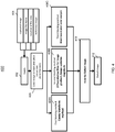
FIG. 4 , aprocessing flow 400 for processing the image data in accordance with one or more embodiments is shown. As shown, atblock 402 several inputs are received at theprocessing module 112 to perform the automated defect detection for the rope using image processing techniques. In one or more embodiments, the inputs received atblock 402 include the set ofdata 404 including the captured image data, image file name, the location of the rope segment, and reference image data. In one or more embodiments, thesystem 100 is configured to receive rope segment information from the hoist or rope dispensing system indicates a location of the length of rope that has been dispensed. This information can include the size and number of turns of a drum that is used to dispense the rope. It should be understood that other techniques that can be used. It should be understood that other data can be received and used in the processing of image data. Atblock 406, image data is converted to black and white for further processing. - A
first marking technique 408A utilizes a Canny transform that is used to compare the edges of the rope to the reference image. For example, loose strand information can be obtained using the Canny transform processing. Asecond marking technique 408B includes a differentiation filter for image gradient/image Laplacian magnitude which is used to compare the current image to the reference image. Each frame can monitor a certain length of the rope and splits the frame into smaller frames/windows for analysis against the reference frame. Athird marking technique 408C includes using block-based pixel color analysis to each segment of the rope. During processing, the image of the current rope can be provided as a matrix that is compared to the reference image that is also provided as a matrix. The two matrices can be compared to each other further compared to the tolerances that are allowed by the threshold settings for that particular rope. Atblock 410, a voting for a defect image of the various marking methods is performed. For example, the marking technique compares the reference image with the actual (defect) image. In addition, the voting process allows for a threshold tolerance for various applications to be used to determine whether the rope is fit for operations or requires repair/replacement. It should be understood that the selection can be selected according to a configurable selection. The resultingdefect image 412 can be provided to the operator in a notification and/or further analysis. - Now referring to
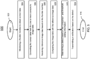
FIG. 5 , a flowchart of amethod 500 for performing automated defect detection for a flexible member using image processing techniques is provided. Themethod 500 begins atblock 502 and proceeds to block 504 which provides for monitoring, by one or more sensors, a flexible member to obtain sensor data. Themethod 500 continues to block 506 and provides for converting the sensor data from the one or more sensors to image data.Block 508 provides for receiving reference image data and threshold setting information. Atblock 510, themethod 500 provides for comparing the image data with the reference image data.Block 512 provides for determining a defect based on the comparison and the threshold setting information. The method atblock 514 provides for transmitting a notification based on the defect. Themethod 500 ends atblock 516. - The technical effects and benefits include real-time rope health monitoring providing prognostic and diagnostic solutions. Therefore there is an increased reliability of the system due to onboard diagnostics. The technical effect and benefits include a reduced time for manual inspections and increased consistency in reporting rope health. There is also an increase in personnel safety when using wire ropes used for human and cargo applications. The system can be made more intelligent with machine learning techniques that are used to analyze the field service data to accurately identify defects and correlate the defects to the remaining life of the rope.
- A detailed description of one or more embodiments of the disclosed apparatus and method are presented herein by way of exemplification and not limitation with reference to the Figures.
- The term "about" is intended to include the degree of error associated with measurement of the particular quantity based upon the equipment available at the time of filing the application.
- The terminology used herein is for the purpose of describing particular embodiments only and is not intended to be limiting of the present disclosure. As used herein, the singular forms "a", "an" and "the" are intended to include the plural forms as well, unless the context clearly indicates otherwise. It will be further understood that the terms "comprises" and/or "comprising," when used in this specification, specify the presence of stated features, integers, steps, operations, elements, and/or components, but do not preclude the presence or addition of one or more other features, integers, steps, operations, element components, and/or groups thereof.
- While the present disclosure has been described with reference to an exemplary embodiment or embodiments, it will be understood by those skilled in the art that various changes may be made and equivalents may be substituted for elements thereof without departing from the scope of the present disclosure. In addition, many modifications may be made to adapt a particular situation or material to the teachings of the present disclosure without departing from the essential scope thereof. Therefore, it is intended that the present disclosure not be limited to the particular embodiment disclosed as the best mode contemplated for carrying out this present disclosure, but that the present disclosure will include all embodiments falling within the scope of the claims.
Claims (15)
- A system (100) for performing automated defect detection for a flexible member using image processing, the system comprising:one or more sensors configured to monitor a flexible member (106);an image processor configured to convert the sensor data from the one or more sensors to image data; anda processing module (110) configured to receive reference image data, compare the image data with the reference image data, determine a defect based on the comparison and a threshold setting information for the flexible member, and transmit a notification based on the defect.
- The system of claim 1, wherein the processing module (110) is configured to determine the defect further comprises categorizing the defect into one or more classes based at least in part on the defect.
- The system of claim 1 or 2, wherein the one or more sensors are optical fibers, and/or
wherein the flexible member is one of rope, wire, belt, and chain. - The system of any preceding claim, wherein the reference image data is based on the flexible member.
- The system of any preceding claim, wherein the threshold setting information is based on an application type for the flexible member.
- The system of any preceding claim, wherein the processing module (110) is configured to determine a location of the defect of the flexible member.
- The system of any preceding claim, wherein the notification comprises a location of the defect, a number of defects, a type of defect, or a recommendation for performing a service relating to the flexible member.
- A method for performing automated defect detection for a flexible member using image processing, the method comprising:monitoring, by one or more sensors, a flexible member (106) to obtain sensor data;converting the sensor data from the one or more sensors to image data;receiving reference image data to compare to the image data;determining a defect based on the comparison and threshold setting information for the flexible member; andtransmitting a notification based on the defect.
- The method of claim 8, wherein determining the defect further comprises categorizing the defect into one or more classes based at least in part on the defect.
- The method of claim 8 or 9, wherein the one or more sensors are optical fibers.
- The method of any of claims 8 to 10, wherein the flexible member is at least one of rope, wire, belt, and chain.
- The method of any of claims 8 to 11, wherein the reference image data is based on the flexible member.
- The method of any of claims 8 to 12, wherein the threshold setting information is based on an application type for the flexible member.
- The method of any of claims 8 to 13, further comprises determining a location of the defect of the flexible member.
- The method of any of claims 8 to 14, wherein the notification comprises a location of the defect, a number of defects, a type of defect, or a recommendation for performing a service relating to the flexible member.
Applications Claiming Priority (1)
| Application Number | Priority Date | Filing Date | Title |
|---|---|---|---|
| IN201811038485 | 2018-10-10 |
Publications (2)
| Publication Number | Publication Date |
|---|---|
| EP3637093A1 true EP3637093A1 (en) | 2020-04-15 |
| EP3637093B1 EP3637093B1 (en) | 2025-06-11 |
Family
ID=68242472
Family Applications (1)
| Application Number | Title | Priority Date | Filing Date |
|---|---|---|---|
| EP19202237.4A Active EP3637093B1 (en) | 2018-10-10 | 2019-10-09 | Automated defect detection for wire rope using image processing techniques |
Country Status (4)
| Country | Link |
|---|---|
| US (1) | US11906445B2 (en) |
| EP (1) | EP3637093B1 (en) |
| CN (1) | CN111024704B (en) |
| CA (1) | CA3057019A1 (en) |
Families Citing this family (15)
| Publication number | Priority date | Publication date | Assignee | Title |
|---|---|---|---|---|
| EP3409629B2 (en) | 2017-06-01 | 2024-02-28 | Otis Elevator Company | Image analytics for elevator maintenance |
| US10870556B2 (en) * | 2017-12-12 | 2020-12-22 | Otis Elevator Company | Method and system for detecting elevator car operating panel condition |
| US10961082B2 (en) | 2018-01-02 | 2021-03-30 | Otis Elevator Company | Elevator inspection using automated sequencing of camera presets |
| US10941018B2 (en) * | 2018-01-04 | 2021-03-09 | Otis Elevator Company | Elevator auto-positioning for validating maintenance |
| US20200122974A1 (en) * | 2018-10-18 | 2020-04-23 | Otis Elevator Company | In-situ system for health monitoring of elevator system |
| WO2021224893A1 (en) * | 2020-05-08 | 2021-11-11 | Sun Chi Chun | Systems and methods for artificial intelligence powered inspections and predictive analyses |
| CN113716417B (en) * | 2021-08-02 | 2025-05-27 | 快意电梯股份有限公司 | Wire rope broken wire and strand sensor and elevator wire rope detection device |
| CN113820274B (en) * | 2021-08-20 | 2023-06-27 | 中国电子科技集团公司第三十八研究所 | Movable hawser quality testing integrated device |
| CN114199146A (en) * | 2021-12-15 | 2022-03-18 | 西安石油大学 | Steel wire rope diameter online detection device and method based on machine vision |
| CN114235825B (en) * | 2022-02-24 | 2022-05-17 | 武汉祥文钢材制品有限公司 | A computer vision-based wire rope quality detection method |
| CN114873398A (en) * | 2022-05-05 | 2022-08-09 | 深圳市富菱楼宇科技有限公司 | Elevator steel wire rope monitoring method and system |
| EP4695763A1 (en) * | 2023-04-12 | 2026-02-18 | Samson Rope Technologies, Inc. | Systems and methods utilizing artificial intelligence for automated visual inspection of ropes |
| CN118883555B (en) * | 2024-06-25 | 2025-03-25 | 荆州市悠进电装有限公司 | A method for monitoring cable surface defects |
| CN119941659B (en) * | 2025-01-02 | 2025-10-10 | 中国兵器装备集团自动化研究所有限公司 | Flexible object detection method, device, equipment and medium |
| CN120147913B (en) * | 2025-05-16 | 2025-07-18 | 陕西省特种设备检验检测研究院 | A cableway aging degree detection system based on image recognition |
Citations (5)
| Publication number | Priority date | Publication date | Assignee | Title |
|---|---|---|---|---|
| WO2001094922A1 (en) * | 1997-10-28 | 2001-12-13 | Materials Technologies Corporation | Apparatus and method for viewing and inspecting a circumferential surface area of an object |
| EP2383566A1 (en) * | 2010-04-28 | 2011-11-02 | Automation W+R GmbH | Method and system for testing ropes |
| WO2012010431A1 (en) * | 2010-07-23 | 2012-01-26 | Inventio Ag | Nondestructive testing of a carrier element of a lift installation |
| WO2017067651A1 (en) * | 2015-10-21 | 2017-04-27 | Liebherr-Components Biberach Gmbh | Device for detecting the replacement state of wear of a high-strength fibre cable for hoisting devices |
| CN106815831A (en) * | 2016-12-21 | 2017-06-09 | 深圳增强现实技术有限公司 | The detection method and device of a kind of steel rope abrasion |
Family Cites Families (36)
| Publication number | Priority date | Publication date | Assignee | Title |
|---|---|---|---|---|
| JPH0656366B2 (en) * | 1988-07-15 | 1994-07-27 | 西日本電線株式会社 | Cable surface defect detector |
| WO1997007627A2 (en) * | 1995-08-17 | 1997-02-27 | Karl Storz Gmbh & Co. | Endoscopy video system |
| US6167150A (en) * | 1998-07-24 | 2000-12-26 | Cognex Corporation | Method and apparatus for detecting extended defects in an object |
| US7277822B2 (en) * | 2000-09-28 | 2007-10-02 | Blemel Kenneth G | Embedded system for diagnostics and prognostics of conduits |
| JP3423304B1 (en) * | 2001-11-09 | 2003-07-07 | シーシーエス株式会社 | Light irradiation device and light irradiation unit |
| US7027934B2 (en) * | 2003-09-24 | 2006-04-11 | 3M Innovative Properties Company | Apparatus and method for automated web inspection |
| US20050273277A1 (en) * | 2004-01-14 | 2005-12-08 | University Of Tennessee Research Foundation, Inc. | Vehicle fatigue life and durability monitoring system and methodology |
| US20050254065A1 (en) * | 2004-05-12 | 2005-11-17 | Stokowski Stanley E | Method and apparatus for detecting surface characteristics on a mask blank |
| DE102005050220A1 (en) | 2005-10-20 | 2007-04-26 | Casar Drahtseilwerk Saar Gmbh | Method and device for inspecting a running wire rope |
| JP4608423B2 (en) * | 2005-12-06 | 2011-01-12 | 新日本製鐵株式会社 | Image shooting device |
| JP2007309696A (en) * | 2006-05-16 | 2007-11-29 | Kirin Techno-System Co Ltd | Surface inspection head device |
| KR100891842B1 (en) * | 2007-08-28 | 2009-04-07 | 주식회사 포스코 | Circular wire rod optical defect detection device and method |
| US20100027998A1 (en) * | 2008-07-31 | 2010-02-04 | Nortel Networks Limited | Optical roundabout switch |
| US8370273B2 (en) | 2009-01-28 | 2013-02-05 | Synopsys, Inc. | Method and apparatus for constructing a canonical representation |
| JP5654737B2 (en) | 2009-07-02 | 2015-01-14 | 第一実業ビスウィル株式会社 | Cord inspection device |
| CA2773747C (en) * | 2009-09-18 | 2017-01-03 | Prysmian S.P.A. | Electric cable with bending sensor and monitoring system and method for detecting bending in at least one electric cable |
| CN102792154B (en) * | 2010-03-10 | 2015-09-23 | 3M创新有限公司 | Repeated defects special in web preparation technology detects |
| US8755589B2 (en) | 2011-09-06 | 2014-06-17 | The Gates Corporation | Measurement of belt wear through edge detection of a raster image |
| DE102011119608B4 (en) * | 2011-11-29 | 2021-07-29 | Karl Storz Se & Co. Kg | Device and method for endoscopic 3D data acquisition |
| JP2014157030A (en) | 2013-02-14 | 2014-08-28 | Raito Kogyo Co Ltd | Steel rope inspection system of ropeway and steel rope inspection method |
| CN103163150B (en) * | 2013-03-18 | 2015-07-15 | 长飞光纤光缆股份有限公司 | Online cable surface defect detection device and online cable surface defect detection method |
| US10352683B2 (en) * | 2014-04-02 | 2019-07-16 | Her Majesty The Queen In Right Of Canada As Represented By The Minister Of Natural Resources Canada | Device for analysis of synthetic rope or cable, and method of use |
| EP3206557B1 (en) * | 2014-10-17 | 2020-06-03 | C Urchin Technologies LLC | Lensless endoscope and other imaging devices |
| CN104849288B (en) * | 2015-05-11 | 2017-12-08 | 华中科技大学 | A kind of detecting system of the cylindrical face surface microscratch defect based on optical fiber image transmission |
| AU2016332056B2 (en) | 2015-09-30 | 2019-02-14 | Samson Rope Technologies, Inc. | Non-destructive evaluation of cordage products |
| US9747683B2 (en) * | 2015-12-21 | 2017-08-29 | General Electric Company | Methods and systems for detecting component wear |
| JP6790401B2 (en) * | 2016-03-24 | 2020-11-25 | 住友電気工業株式会社 | Optical fiber inspection equipment, optical fiber manufacturing equipment, and optical fiber manufacturing method |
| US10717631B2 (en) * | 2016-11-22 | 2020-07-21 | Manitowoc Crane Companies, Llc | Optical detection and analysis of crane hoist and rope |
| DE102016124522A1 (en) | 2016-12-15 | 2018-06-21 | Thyssenkrupp Ag | Method of inspecting a steel strip |
| CN106841381B (en) | 2017-03-17 | 2020-07-07 | 太原理工大学 | Steel wire rope online flaw detection monitoring system and method and mining multi-rope friction lifting system |
| CN107014828B (en) * | 2017-05-25 | 2023-10-13 | 济南大学 | Dual-wavelength coaxial optical fiber sensor and method for detecting surface defects of steel balls |
| CN206891999U (en) * | 2017-05-27 | 2018-01-16 | 杭州魔方智能科技有限公司 | Cable open defect detection means |
| CN107192720A (en) * | 2017-06-01 | 2017-09-22 | 三峡大学 | A kind of intermediate joint of electric cable stripping quality detecting system and detection method |
| CN107764839B (en) | 2017-10-12 | 2020-05-05 | 中南大学 | Machine vision-based steel wire rope surface defect online detection method and device |
| DE102017126134A1 (en) * | 2017-11-08 | 2019-05-09 | Claas Industrietechnik Gmbh | caterpillar |
| CN208459294U (en) | 2018-07-12 | 2019-02-01 | 武汉意普科技有限责任公司 | A kind of surface quality of strips vision inspection apparatus |
-
2018
- 2018-12-06 US US16/211,339 patent/US11906445B2/en active Active
-
2019
- 2019-09-26 CA CA3057019A patent/CA3057019A1/en active Pending
- 2019-10-09 EP EP19202237.4A patent/EP3637093B1/en active Active
- 2019-10-09 CN CN201910953694.3A patent/CN111024704B/en active Active
Patent Citations (5)
| Publication number | Priority date | Publication date | Assignee | Title |
|---|---|---|---|---|
| WO2001094922A1 (en) * | 1997-10-28 | 2001-12-13 | Materials Technologies Corporation | Apparatus and method for viewing and inspecting a circumferential surface area of an object |
| EP2383566A1 (en) * | 2010-04-28 | 2011-11-02 | Automation W+R GmbH | Method and system for testing ropes |
| WO2012010431A1 (en) * | 2010-07-23 | 2012-01-26 | Inventio Ag | Nondestructive testing of a carrier element of a lift installation |
| WO2017067651A1 (en) * | 2015-10-21 | 2017-04-27 | Liebherr-Components Biberach Gmbh | Device for detecting the replacement state of wear of a high-strength fibre cable for hoisting devices |
| CN106815831A (en) * | 2016-12-21 | 2017-06-09 | 深圳增强现实技术有限公司 | The detection method and device of a kind of steel rope abrasion |
Also Published As
| Publication number | Publication date |
|---|---|
| US20200118259A1 (en) | 2020-04-16 |
| EP3637093B1 (en) | 2025-06-11 |
| CA3057019A1 (en) | 2020-04-10 |
| US11906445B2 (en) | 2024-02-20 |
| BR102019021121A2 (en) | 2020-04-28 |
| CN111024704B (en) | 2025-05-13 |
| CN111024704A (en) | 2020-04-17 |
Similar Documents
| Publication | Publication Date | Title |
|---|---|---|
| EP3637093B1 (en) | Automated defect detection for wire rope using image processing techniques | |
| KR102105568B1 (en) | System for structural diagnosis using unmanned aerial vehicle and method for structural diagnosis using it | |
| US9063008B2 (en) | Nondestructive testing of a carrier element of an elevator installation | |
| CA2737897C (en) | System and method for testing ropes | |
| EP3488307B1 (en) | Methods for predicting and preventing failure of in vitro diagnostic instruments | |
| KR102303406B1 (en) | Method for something wrong diagnosis of industrial equipment and the device | |
| EP3973364B1 (en) | System and method for determining a health condition and an anomaly of an equipment | |
| CN109823941B (en) | Be applied to wire rope monitoring devices on initiative safety elevator | |
| CN118255227A (en) | An elevator status warning system based on sensor data acquisition and AI algorithm | |
| KR102192783B1 (en) | Video recording device for badness cause analytical of product | |
| KR20250157324A (en) | Multi-acoustic identification device and alarm system for equipment abnormality using it | |
| KR102522496B1 (en) | Module type operation and management device for management facilities | |
| KR20190030020A (en) | Sytem for fault diagnosis of electrical equipment through analysis of temperature and current | |
| CN108016959B (en) | Automatic detection equipment and method for automatically detecting state in well | |
| US20250027846A1 (en) | System and method for vibration analysis | |
| BR102019021121B1 (en) | SYSTEM AND METHOD FOR PERFORMING AUTOMATED DEFECT DETECTION | |
| CN120214257A (en) | Pipeline inner wall corrosion monitoring system and method | |
| JP7336020B2 (en) | Method for generating an image of an elevator rope, controller and computer program product for performing the method | |
| JP7668775B2 (en) | Wire rope inspection method and inspection system, and crane | |
| KR102514608B1 (en) | Detachable cctv failure self-diagnosis apparatus | |
| US20250076214A1 (en) | Rope evaluation systems and methods | |
| US20190323923A1 (en) | Electric drive unit having intelligent maintenance requirement montoring | |
| KR20240054786A (en) | Structure diagnosis method and structure diagnosis system using unmanned aerial vehicle | |
| CN113011524A (en) | Method and device for identifying state of hoisting steel wire rope, operation machine and electronic equipment | |
| KR102195266B1 (en) | Fault diagnosis method for plant using sound signal |
Legal Events
| Date | Code | Title | Description |
|---|---|---|---|
| PUAI | Public reference made under article 153(3) epc to a published international application that has entered the european phase |
Free format text: ORIGINAL CODE: 0009012 |
|
| STAA | Information on the status of an ep patent application or granted ep patent |
Free format text: STATUS: THE APPLICATION HAS BEEN PUBLISHED |
|
| AK | Designated contracting states |
Kind code of ref document: A1 Designated state(s): AL AT BE BG CH CY CZ DE DK EE ES FI FR GB GR HR HU IE IS IT LI LT LU LV MC MK MT NL NO PL PT RO RS SE SI SK SM TR |
|
| AX | Request for extension of the european patent |
Extension state: BA ME |
|
| STAA | Information on the status of an ep patent application or granted ep patent |
Free format text: STATUS: REQUEST FOR EXAMINATION WAS MADE |
|
| 17P | Request for examination filed |
Effective date: 20201015 |
|
| RBV | Designated contracting states (corrected) |
Designated state(s): AL AT BE BG CH CY CZ DE DK EE ES FI FR GB GR HR HU IE IS IT LI LT LU LV MC MK MT NL NO PL PT RO RS SE SI SK SM TR |
|
| STAA | Information on the status of an ep patent application or granted ep patent |
Free format text: STATUS: EXAMINATION IS IN PROGRESS |
|
| 17Q | First examination report despatched |
Effective date: 20211221 |
|
| P01 | Opt-out of the competence of the unified patent court (upc) registered |
Effective date: 20230922 |
|
| GRAP | Despatch of communication of intention to grant a patent |
Free format text: ORIGINAL CODE: EPIDOSNIGR1 |
|
| STAA | Information on the status of an ep patent application or granted ep patent |
Free format text: STATUS: GRANT OF PATENT IS INTENDED |
|
| INTG | Intention to grant announced |
Effective date: 20250114 |
|
| RAP1 | Party data changed (applicant data changed or rights of an application transferred) |
Owner name: HORNET ACQUISITIONCO, LLC |
|
| GRAS | Grant fee paid |
Free format text: ORIGINAL CODE: EPIDOSNIGR3 |
|
| GRAA | (expected) grant |
Free format text: ORIGINAL CODE: 0009210 |
|
| STAA | Information on the status of an ep patent application or granted ep patent |
Free format text: STATUS: THE PATENT HAS BEEN GRANTED |
|
| AK | Designated contracting states |
Kind code of ref document: B1 Designated state(s): AL AT BE BG CH CY CZ DE DK EE ES FI FR GB GR HR HU IE IS IT LI LT LU LV MC MK MT NL NO PL PT RO RS SE SI SK SM TR |
|
| REG | Reference to a national code |
Ref country code: GB Ref legal event code: FG4D |
|
| REG | Reference to a national code |
Ref country code: CH Ref legal event code: EP |
|
| REG | Reference to a national code |
Ref country code: IE Ref legal event code: FG4D |
|
| REG | Reference to a national code |
Ref country code: DE Ref legal event code: R096 Ref document number: 602019070981 Country of ref document: DE |
|
| PG25 | Lapsed in a contracting state [announced via postgrant information from national office to epo] |
Ref country code: FI Free format text: LAPSE BECAUSE OF FAILURE TO SUBMIT A TRANSLATION OF THE DESCRIPTION OR TO PAY THE FEE WITHIN THE PRESCRIBED TIME-LIMIT Effective date: 20250611 Ref country code: ES Free format text: LAPSE BECAUSE OF FAILURE TO SUBMIT A TRANSLATION OF THE DESCRIPTION OR TO PAY THE FEE WITHIN THE PRESCRIBED TIME-LIMIT Effective date: 20250611 |
|
| REG | Reference to a national code |
Ref country code: LT Ref legal event code: MG9D |
|
| PG25 | Lapsed in a contracting state [announced via postgrant information from national office to epo] |
Ref country code: NO Free format text: LAPSE BECAUSE OF FAILURE TO SUBMIT A TRANSLATION OF THE DESCRIPTION OR TO PAY THE FEE WITHIN THE PRESCRIBED TIME-LIMIT Effective date: 20250911 Ref country code: GR Free format text: LAPSE BECAUSE OF FAILURE TO SUBMIT A TRANSLATION OF THE DESCRIPTION OR TO PAY THE FEE WITHIN THE PRESCRIBED TIME-LIMIT Effective date: 20250912 |
|
| REG | Reference to a national code |
Ref country code: NL Ref legal event code: MP Effective date: 20250611 |
|
| PG25 | Lapsed in a contracting state [announced via postgrant information from national office to epo] |
Ref country code: BG Free format text: LAPSE BECAUSE OF FAILURE TO SUBMIT A TRANSLATION OF THE DESCRIPTION OR TO PAY THE FEE WITHIN THE PRESCRIBED TIME-LIMIT Effective date: 20250611 |
|
| PG25 | Lapsed in a contracting state [announced via postgrant information from national office to epo] |
Ref country code: HR Free format text: LAPSE BECAUSE OF FAILURE TO SUBMIT A TRANSLATION OF THE DESCRIPTION OR TO PAY THE FEE WITHIN THE PRESCRIBED TIME-LIMIT Effective date: 20250611 |
|
| PG25 | Lapsed in a contracting state [announced via postgrant information from national office to epo] |
Ref country code: RS Free format text: LAPSE BECAUSE OF FAILURE TO SUBMIT A TRANSLATION OF THE DESCRIPTION OR TO PAY THE FEE WITHIN THE PRESCRIBED TIME-LIMIT Effective date: 20250911 |
|
| PG25 | Lapsed in a contracting state [announced via postgrant information from national office to epo] |
Ref country code: LV Free format text: LAPSE BECAUSE OF FAILURE TO SUBMIT A TRANSLATION OF THE DESCRIPTION OR TO PAY THE FEE WITHIN THE PRESCRIBED TIME-LIMIT Effective date: 20250611 |
|
| PG25 | Lapsed in a contracting state [announced via postgrant information from national office to epo] |
Ref country code: NL Free format text: LAPSE BECAUSE OF FAILURE TO SUBMIT A TRANSLATION OF THE DESCRIPTION OR TO PAY THE FEE WITHIN THE PRESCRIBED TIME-LIMIT Effective date: 20250611 |
|
| PG25 | Lapsed in a contracting state [announced via postgrant information from national office to epo] |
Ref country code: PT Free format text: LAPSE BECAUSE OF FAILURE TO SUBMIT A TRANSLATION OF THE DESCRIPTION OR TO PAY THE FEE WITHIN THE PRESCRIBED TIME-LIMIT Effective date: 20251013 |
|
| REG | Reference to a national code |
Ref country code: AT Ref legal event code: MK05 Ref document number: 1802633 Country of ref document: AT Kind code of ref document: T Effective date: 20250611 |
|
| PG25 | Lapsed in a contracting state [announced via postgrant information from national office to epo] |
Ref country code: IS Free format text: LAPSE BECAUSE OF FAILURE TO SUBMIT A TRANSLATION OF THE DESCRIPTION OR TO PAY THE FEE WITHIN THE PRESCRIBED TIME-LIMIT Effective date: 20251011 |
|
| PGFP | Annual fee paid to national office [announced via postgrant information from national office to epo] |
Ref country code: DE Payment date: 20251029 Year of fee payment: 7 |
|
| PGFP | Annual fee paid to national office [announced via postgrant information from national office to epo] |
Ref country code: GB Payment date: 20251027 Year of fee payment: 7 |
|
| PG25 | Lapsed in a contracting state [announced via postgrant information from national office to epo] |
Ref country code: AT Free format text: LAPSE BECAUSE OF FAILURE TO SUBMIT A TRANSLATION OF THE DESCRIPTION OR TO PAY THE FEE WITHIN THE PRESCRIBED TIME-LIMIT Effective date: 20250611 Ref country code: SM Free format text: LAPSE BECAUSE OF FAILURE TO SUBMIT A TRANSLATION OF THE DESCRIPTION OR TO PAY THE FEE WITHIN THE PRESCRIBED TIME-LIMIT Effective date: 20250611 |
|
| PGFP | Annual fee paid to national office [announced via postgrant information from national office to epo] |
Ref country code: FR Payment date: 20251027 Year of fee payment: 7 |
|
| PG25 | Lapsed in a contracting state [announced via postgrant information from national office to epo] |
Ref country code: CZ Free format text: LAPSE BECAUSE OF FAILURE TO SUBMIT A TRANSLATION OF THE DESCRIPTION OR TO PAY THE FEE WITHIN THE PRESCRIBED TIME-LIMIT Effective date: 20250611 |
|
| PG25 | Lapsed in a contracting state [announced via postgrant information from national office to epo] |
Ref country code: PL Free format text: LAPSE BECAUSE OF FAILURE TO SUBMIT A TRANSLATION OF THE DESCRIPTION OR TO PAY THE FEE WITHIN THE PRESCRIBED TIME-LIMIT Effective date: 20250611 |
|
| PG25 | Lapsed in a contracting state [announced via postgrant information from national office to epo] |
Ref country code: EE Free format text: LAPSE BECAUSE OF FAILURE TO SUBMIT A TRANSLATION OF THE DESCRIPTION OR TO PAY THE FEE WITHIN THE PRESCRIBED TIME-LIMIT Effective date: 20250611 |
|
| PG25 | Lapsed in a contracting state [announced via postgrant information from national office to epo] |
Ref country code: SK Free format text: LAPSE BECAUSE OF FAILURE TO SUBMIT A TRANSLATION OF THE DESCRIPTION OR TO PAY THE FEE WITHIN THE PRESCRIBED TIME-LIMIT Effective date: 20250611 Ref country code: RO Free format text: LAPSE BECAUSE OF FAILURE TO SUBMIT A TRANSLATION OF THE DESCRIPTION OR TO PAY THE FEE WITHIN THE PRESCRIBED TIME-LIMIT Effective date: 20250611 |
|
| REG | Reference to a national code |
Ref country code: DE Ref legal event code: R097 Ref document number: 602019070981 Country of ref document: DE |
|
| PG25 | Lapsed in a contracting state [announced via postgrant information from national office to epo] |
Ref country code: DK Free format text: LAPSE BECAUSE OF FAILURE TO SUBMIT A TRANSLATION OF THE DESCRIPTION OR TO PAY THE FEE WITHIN THE PRESCRIBED TIME-LIMIT Effective date: 20250611 |
|
| PG25 | Lapsed in a contracting state [announced via postgrant information from national office to epo] |
Ref country code: IT Free format text: LAPSE BECAUSE OF FAILURE TO SUBMIT A TRANSLATION OF THE DESCRIPTION OR TO PAY THE FEE WITHIN THE PRESCRIBED TIME-LIMIT Effective date: 20250611 |
|
| PLBE | No opposition filed within time limit |
Free format text: ORIGINAL CODE: 0009261 |
|
| STAA | Information on the status of an ep patent application or granted ep patent |
Free format text: STATUS: NO OPPOSITION FILED WITHIN TIME LIMIT |
|
| REG | Reference to a national code |
Ref country code: CH Ref legal event code: L10 Free format text: ST27 STATUS EVENT CODE: U-0-0-L10-L00 (AS PROVIDED BY THE NATIONAL OFFICE) Effective date: 20260423 |