EP3636958A1 - Vehicle drive system - Google Patents
Vehicle drive system Download PDFInfo
- Publication number
- EP3636958A1 EP3636958A1 EP19199249.4A EP19199249A EP3636958A1 EP 3636958 A1 EP3636958 A1 EP 3636958A1 EP 19199249 A EP19199249 A EP 19199249A EP 3636958 A1 EP3636958 A1 EP 3636958A1
- Authority
- EP
- European Patent Office
- Prior art keywords
- vehicle
- drive
- motor
- drive force
- internal combustion
- Prior art date
- Legal status (The legal status is an assumption and is not a legal conclusion. Google has not performed a legal analysis and makes no representation as to the accuracy of the status listed.)
- Withdrawn
Links
Images



Classifications
-
- B—PERFORMING OPERATIONS; TRANSPORTING
- B60—VEHICLES IN GENERAL
- B60K—ARRANGEMENT OR MOUNTING OF PROPULSION UNITS OR OF TRANSMISSIONS IN VEHICLES; ARRANGEMENT OR MOUNTING OF PLURAL DIVERSE PRIME-MOVERS IN VEHICLES; AUXILIARY DRIVES FOR VEHICLES; INSTRUMENTATION OR DASHBOARDS FOR VEHICLES; ARRANGEMENTS IN CONNECTION WITH COOLING, AIR INTAKE, GAS EXHAUST OR FUEL SUPPLY OF PROPULSION UNITS IN VEHICLES
- B60K6/00—Arrangement or mounting of plural diverse prime-movers for mutual or common propulsion, e.g. hybrid propulsion systems comprising electric motors and internal combustion engines
- B60K6/20—Arrangement or mounting of plural diverse prime-movers for mutual or common propulsion, e.g. hybrid propulsion systems comprising electric motors and internal combustion engines the prime-movers consisting of electric motors and internal combustion engines, e.g. HEVs
- B60K6/42—Arrangement or mounting of plural diverse prime-movers for mutual or common propulsion, e.g. hybrid propulsion systems comprising electric motors and internal combustion engines the prime-movers consisting of electric motors and internal combustion engines, e.g. HEVs characterised by the architecture of the hybrid electric vehicle
- B60K6/48—Parallel type
-
- B—PERFORMING OPERATIONS; TRANSPORTING
- B60—VEHICLES IN GENERAL
- B60W—CONJOINT CONTROL OF VEHICLE SUB-UNITS OF DIFFERENT TYPE OR DIFFERENT FUNCTION; CONTROL SYSTEMS SPECIALLY ADAPTED FOR HYBRID VEHICLES; ROAD VEHICLE DRIVE CONTROL SYSTEMS FOR PURPOSES NOT RELATED TO THE CONTROL OF A PARTICULAR SUB-UNIT
- B60W20/00—Control systems specially adapted for hybrid vehicles
- B60W20/20—Control strategies involving selection of hybrid configuration, e.g. selection between series or parallel configuration
-
- B—PERFORMING OPERATIONS; TRANSPORTING
- B60—VEHICLES IN GENERAL
- B60W—CONJOINT CONTROL OF VEHICLE SUB-UNITS OF DIFFERENT TYPE OR DIFFERENT FUNCTION; CONTROL SYSTEMS SPECIALLY ADAPTED FOR HYBRID VEHICLES; ROAD VEHICLE DRIVE CONTROL SYSTEMS FOR PURPOSES NOT RELATED TO THE CONTROL OF A PARTICULAR SUB-UNIT
- B60W20/00—Control systems specially adapted for hybrid vehicles
- B60W20/10—Controlling the power contribution of each of the prime movers to meet required power demand
- B60W20/15—Control strategies specially adapted for achieving a particular effect
- B60W20/19—Control strategies specially adapted for achieving a particular effect for achieving enhanced acceleration
-
- B—PERFORMING OPERATIONS; TRANSPORTING
- B60—VEHICLES IN GENERAL
- B60K—ARRANGEMENT OR MOUNTING OF PROPULSION UNITS OR OF TRANSMISSIONS IN VEHICLES; ARRANGEMENT OR MOUNTING OF PLURAL DIVERSE PRIME-MOVERS IN VEHICLES; AUXILIARY DRIVES FOR VEHICLES; INSTRUMENTATION OR DASHBOARDS FOR VEHICLES; ARRANGEMENTS IN CONNECTION WITH COOLING, AIR INTAKE, GAS EXHAUST OR FUEL SUPPLY OF PROPULSION UNITS IN VEHICLES
- B60K6/00—Arrangement or mounting of plural diverse prime-movers for mutual or common propulsion, e.g. hybrid propulsion systems comprising electric motors and internal combustion engines
- B60K6/20—Arrangement or mounting of plural diverse prime-movers for mutual or common propulsion, e.g. hybrid propulsion systems comprising electric motors and internal combustion engines the prime-movers consisting of electric motors and internal combustion engines, e.g. HEVs
- B60K6/22—Arrangement or mounting of plural diverse prime-movers for mutual or common propulsion, e.g. hybrid propulsion systems comprising electric motors and internal combustion engines the prime-movers consisting of electric motors and internal combustion engines, e.g. HEVs characterised by apparatus, components or means specially adapted for HEVs
- B60K6/24—Arrangement or mounting of plural diverse prime-movers for mutual or common propulsion, e.g. hybrid propulsion systems comprising electric motors and internal combustion engines the prime-movers consisting of electric motors and internal combustion engines, e.g. HEVs characterised by apparatus, components or means specially adapted for HEVs characterised by the combustion engines
-
- B—PERFORMING OPERATIONS; TRANSPORTING
- B60—VEHICLES IN GENERAL
- B60K—ARRANGEMENT OR MOUNTING OF PROPULSION UNITS OR OF TRANSMISSIONS IN VEHICLES; ARRANGEMENT OR MOUNTING OF PLURAL DIVERSE PRIME-MOVERS IN VEHICLES; AUXILIARY DRIVES FOR VEHICLES; INSTRUMENTATION OR DASHBOARDS FOR VEHICLES; ARRANGEMENTS IN CONNECTION WITH COOLING, AIR INTAKE, GAS EXHAUST OR FUEL SUPPLY OF PROPULSION UNITS IN VEHICLES
- B60K6/00—Arrangement or mounting of plural diverse prime-movers for mutual or common propulsion, e.g. hybrid propulsion systems comprising electric motors and internal combustion engines
- B60K6/20—Arrangement or mounting of plural diverse prime-movers for mutual or common propulsion, e.g. hybrid propulsion systems comprising electric motors and internal combustion engines the prime-movers consisting of electric motors and internal combustion engines, e.g. HEVs
- B60K6/22—Arrangement or mounting of plural diverse prime-movers for mutual or common propulsion, e.g. hybrid propulsion systems comprising electric motors and internal combustion engines the prime-movers consisting of electric motors and internal combustion engines, e.g. HEVs characterised by apparatus, components or means specially adapted for HEVs
- B60K6/26—Arrangement or mounting of plural diverse prime-movers for mutual or common propulsion, e.g. hybrid propulsion systems comprising electric motors and internal combustion engines the prime-movers consisting of electric motors and internal combustion engines, e.g. HEVs characterised by apparatus, components or means specially adapted for HEVs characterised by the motors or the generators
-
- B—PERFORMING OPERATIONS; TRANSPORTING
- B60—VEHICLES IN GENERAL
- B60K—ARRANGEMENT OR MOUNTING OF PROPULSION UNITS OR OF TRANSMISSIONS IN VEHICLES; ARRANGEMENT OR MOUNTING OF PLURAL DIVERSE PRIME-MOVERS IN VEHICLES; AUXILIARY DRIVES FOR VEHICLES; INSTRUMENTATION OR DASHBOARDS FOR VEHICLES; ARRANGEMENTS IN CONNECTION WITH COOLING, AIR INTAKE, GAS EXHAUST OR FUEL SUPPLY OF PROPULSION UNITS IN VEHICLES
- B60K6/00—Arrangement or mounting of plural diverse prime-movers for mutual or common propulsion, e.g. hybrid propulsion systems comprising electric motors and internal combustion engines
- B60K6/20—Arrangement or mounting of plural diverse prime-movers for mutual or common propulsion, e.g. hybrid propulsion systems comprising electric motors and internal combustion engines the prime-movers consisting of electric motors and internal combustion engines, e.g. HEVs
- B60K6/22—Arrangement or mounting of plural diverse prime-movers for mutual or common propulsion, e.g. hybrid propulsion systems comprising electric motors and internal combustion engines the prime-movers consisting of electric motors and internal combustion engines, e.g. HEVs characterised by apparatus, components or means specially adapted for HEVs
- B60K6/36—Arrangement or mounting of plural diverse prime-movers for mutual or common propulsion, e.g. hybrid propulsion systems comprising electric motors and internal combustion engines the prime-movers consisting of electric motors and internal combustion engines, e.g. HEVs characterised by apparatus, components or means specially adapted for HEVs characterised by the transmission gearings
-
- B—PERFORMING OPERATIONS; TRANSPORTING
- B60—VEHICLES IN GENERAL
- B60K—ARRANGEMENT OR MOUNTING OF PROPULSION UNITS OR OF TRANSMISSIONS IN VEHICLES; ARRANGEMENT OR MOUNTING OF PLURAL DIVERSE PRIME-MOVERS IN VEHICLES; AUXILIARY DRIVES FOR VEHICLES; INSTRUMENTATION OR DASHBOARDS FOR VEHICLES; ARRANGEMENTS IN CONNECTION WITH COOLING, AIR INTAKE, GAS EXHAUST OR FUEL SUPPLY OF PROPULSION UNITS IN VEHICLES
- B60K6/00—Arrangement or mounting of plural diverse prime-movers for mutual or common propulsion, e.g. hybrid propulsion systems comprising electric motors and internal combustion engines
- B60K6/20—Arrangement or mounting of plural diverse prime-movers for mutual or common propulsion, e.g. hybrid propulsion systems comprising electric motors and internal combustion engines the prime-movers consisting of electric motors and internal combustion engines, e.g. HEVs
- B60K6/50—Architecture of the driveline characterised by arrangement or kind of transmission units
- B60K6/52—Driving a plurality of drive axles, e.g. four-wheel drive
-
- B—PERFORMING OPERATIONS; TRANSPORTING
- B60—VEHICLES IN GENERAL
- B60K—ARRANGEMENT OR MOUNTING OF PROPULSION UNITS OR OF TRANSMISSIONS IN VEHICLES; ARRANGEMENT OR MOUNTING OF PLURAL DIVERSE PRIME-MOVERS IN VEHICLES; AUXILIARY DRIVES FOR VEHICLES; INSTRUMENTATION OR DASHBOARDS FOR VEHICLES; ARRANGEMENTS IN CONNECTION WITH COOLING, AIR INTAKE, GAS EXHAUST OR FUEL SUPPLY OF PROPULSION UNITS IN VEHICLES
- B60K7/00—Disposition of motor in, or adjacent to, traction wheel
- B60K7/0007—Disposition of motor in, or adjacent to, traction wheel the motor being electric
-
- B—PERFORMING OPERATIONS; TRANSPORTING
- B60—VEHICLES IN GENERAL
- B60W—CONJOINT CONTROL OF VEHICLE SUB-UNITS OF DIFFERENT TYPE OR DIFFERENT FUNCTION; CONTROL SYSTEMS SPECIALLY ADAPTED FOR HYBRID VEHICLES; ROAD VEHICLE DRIVE CONTROL SYSTEMS FOR PURPOSES NOT RELATED TO THE CONTROL OF A PARTICULAR SUB-UNIT
- B60W10/00—Conjoint control of vehicle sub-units of different type or different function
- B60W10/04—Conjoint control of vehicle sub-units of different type or different function including control of propulsion units
- B60W10/06—Conjoint control of vehicle sub-units of different type or different function including control of propulsion units including control of combustion engines
-
- B—PERFORMING OPERATIONS; TRANSPORTING
- B60—VEHICLES IN GENERAL
- B60W—CONJOINT CONTROL OF VEHICLE SUB-UNITS OF DIFFERENT TYPE OR DIFFERENT FUNCTION; CONTROL SYSTEMS SPECIALLY ADAPTED FOR HYBRID VEHICLES; ROAD VEHICLE DRIVE CONTROL SYSTEMS FOR PURPOSES NOT RELATED TO THE CONTROL OF A PARTICULAR SUB-UNIT
- B60W10/00—Conjoint control of vehicle sub-units of different type or different function
- B60W10/04—Conjoint control of vehicle sub-units of different type or different function including control of propulsion units
- B60W10/08—Conjoint control of vehicle sub-units of different type or different function including control of propulsion units including control of electric propulsion units, e.g. motors or generators
-
- B—PERFORMING OPERATIONS; TRANSPORTING
- B60—VEHICLES IN GENERAL
- B60W—CONJOINT CONTROL OF VEHICLE SUB-UNITS OF DIFFERENT TYPE OR DIFFERENT FUNCTION; CONTROL SYSTEMS SPECIALLY ADAPTED FOR HYBRID VEHICLES; ROAD VEHICLE DRIVE CONTROL SYSTEMS FOR PURPOSES NOT RELATED TO THE CONTROL OF A PARTICULAR SUB-UNIT
- B60W10/00—Conjoint control of vehicle sub-units of different type or different function
- B60W10/10—Conjoint control of vehicle sub-units of different type or different function including control of change-speed gearings
- B60W10/11—Stepped gearings
-
- B—PERFORMING OPERATIONS; TRANSPORTING
- B60—VEHICLES IN GENERAL
- B60W—CONJOINT CONTROL OF VEHICLE SUB-UNITS OF DIFFERENT TYPE OR DIFFERENT FUNCTION; CONTROL SYSTEMS SPECIALLY ADAPTED FOR HYBRID VEHICLES; ROAD VEHICLE DRIVE CONTROL SYSTEMS FOR PURPOSES NOT RELATED TO THE CONTROL OF A PARTICULAR SUB-UNIT
- B60W20/00—Control systems specially adapted for hybrid vehicles
- B60W20/40—Controlling the engagement or disengagement of prime movers, e.g. for transition between prime movers
-
- B—PERFORMING OPERATIONS; TRANSPORTING
- B60—VEHICLES IN GENERAL
- B60W—CONJOINT CONTROL OF VEHICLE SUB-UNITS OF DIFFERENT TYPE OR DIFFERENT FUNCTION; CONTROL SYSTEMS SPECIALLY ADAPTED FOR HYBRID VEHICLES; ROAD VEHICLE DRIVE CONTROL SYSTEMS FOR PURPOSES NOT RELATED TO THE CONTROL OF A PARTICULAR SUB-UNIT
- B60W30/00—Purposes of road vehicle drive control systems not related to the control of a particular sub-unit, e.g. of systems using conjoint control of vehicle sub-units
- B60W30/02—Control of vehicle driving stability
- B60W30/025—Control of vehicle driving stability related to comfort of drivers or passengers
-
- B—PERFORMING OPERATIONS; TRANSPORTING
- B60—VEHICLES IN GENERAL
- B60W—CONJOINT CONTROL OF VEHICLE SUB-UNITS OF DIFFERENT TYPE OR DIFFERENT FUNCTION; CONTROL SYSTEMS SPECIALLY ADAPTED FOR HYBRID VEHICLES; ROAD VEHICLE DRIVE CONTROL SYSTEMS FOR PURPOSES NOT RELATED TO THE CONTROL OF A PARTICULAR SUB-UNIT
- B60W30/00—Purposes of road vehicle drive control systems not related to the control of a particular sub-unit, e.g. of systems using conjoint control of vehicle sub-units
- B60W30/18—Propelling the vehicle
- B60W30/19—Improvement of gear change, e.g. by synchronisation or smoothing gear shift
-
- F—MECHANICAL ENGINEERING; LIGHTING; HEATING; WEAPONS; BLASTING
- F16—ENGINEERING ELEMENTS AND UNITS; GENERAL MEASURES FOR PRODUCING AND MAINTAINING EFFECTIVE FUNCTIONING OF MACHINES OR INSTALLATIONS; THERMAL INSULATION IN GENERAL
- F16H—GEARING
- F16H3/00—Toothed gearings for conveying rotary motion with variable gear ratio or for reversing rotary motion
- F16H3/02—Toothed gearings for conveying rotary motion with variable gear ratio or for reversing rotary motion without gears having orbital motion
- F16H3/08—Toothed gearings for conveying rotary motion with variable gear ratio or for reversing rotary motion without gears having orbital motion exclusively or essentially with continuously meshing gears, that can be disengaged from their shafts
- F16H3/087—Toothed gearings for conveying rotary motion with variable gear ratio or for reversing rotary motion without gears having orbital motion exclusively or essentially with continuously meshing gears, that can be disengaged from their shafts characterised by the disposition of the gears
- F16H3/089—Toothed gearings for conveying rotary motion with variable gear ratio or for reversing rotary motion without gears having orbital motion exclusively or essentially with continuously meshing gears, that can be disengaged from their shafts characterised by the disposition of the gears all of the meshing gears being supported by a pair of parallel shafts, one being the input shaft and the other the output shaft, there being no countershaft involved
-
- F—MECHANICAL ENGINEERING; LIGHTING; HEATING; WEAPONS; BLASTING
- F16—ENGINEERING ELEMENTS AND UNITS; GENERAL MEASURES FOR PRODUCING AND MAINTAINING EFFECTIVE FUNCTIONING OF MACHINES OR INSTALLATIONS; THERMAL INSULATION IN GENERAL
- F16H—GEARING
- F16H61/00—Control functions within control units of change-speed- or reversing-gearings for conveying rotary motion ; Control of exclusively fluid gearing, friction gearing, gearings with endless flexible members or other particular types of gearing
- F16H61/04—Smoothing ratio shift
-
- F—MECHANICAL ENGINEERING; LIGHTING; HEATING; WEAPONS; BLASTING
- F16—ENGINEERING ELEMENTS AND UNITS; GENERAL MEASURES FOR PRODUCING AND MAINTAINING EFFECTIVE FUNCTIONING OF MACHINES OR INSTALLATIONS; THERMAL INSULATION IN GENERAL
- F16H—GEARING
- F16H63/00—Control outputs from the control unit to change-speed- or reversing-gearings for conveying rotary motion or to other devices than the final output mechanism
- F16H63/02—Final output mechanisms therefor; Actuating means for the final output mechanisms
- F16H63/08—Multiple final output mechanisms being moved by a single common final actuating mechanism
- F16H63/16—Multiple final output mechanisms being moved by a single common final actuating mechanism the final output mechanisms being successively actuated by progressive movement of the final actuating mechanism
- F16H63/18—Multiple final output mechanisms being moved by a single common final actuating mechanism the final output mechanisms being successively actuated by progressive movement of the final actuating mechanism the final actuating mechanism comprising cams
-
- B—PERFORMING OPERATIONS; TRANSPORTING
- B60—VEHICLES IN GENERAL
- B60K—ARRANGEMENT OR MOUNTING OF PROPULSION UNITS OR OF TRANSMISSIONS IN VEHICLES; ARRANGEMENT OR MOUNTING OF PLURAL DIVERSE PRIME-MOVERS IN VEHICLES; AUXILIARY DRIVES FOR VEHICLES; INSTRUMENTATION OR DASHBOARDS FOR VEHICLES; ARRANGEMENTS IN CONNECTION WITH COOLING, AIR INTAKE, GAS EXHAUST OR FUEL SUPPLY OF PROPULSION UNITS IN VEHICLES
- B60K7/00—Disposition of motor in, or adjacent to, traction wheel
- B60K2007/0038—Disposition of motor in, or adjacent to, traction wheel the motor moving together with the wheel axle
-
- B—PERFORMING OPERATIONS; TRANSPORTING
- B60—VEHICLES IN GENERAL
- B60K—ARRANGEMENT OR MOUNTING OF PROPULSION UNITS OR OF TRANSMISSIONS IN VEHICLES; ARRANGEMENT OR MOUNTING OF PLURAL DIVERSE PRIME-MOVERS IN VEHICLES; AUXILIARY DRIVES FOR VEHICLES; INSTRUMENTATION OR DASHBOARDS FOR VEHICLES; ARRANGEMENTS IN CONNECTION WITH COOLING, AIR INTAKE, GAS EXHAUST OR FUEL SUPPLY OF PROPULSION UNITS IN VEHICLES
- B60K7/00—Disposition of motor in, or adjacent to, traction wheel
- B60K2007/0092—Disposition of motor in, or adjacent to, traction wheel the motor axle being coaxial to the wheel axle
-
- F—MECHANICAL ENGINEERING; LIGHTING; HEATING; WEAPONS; BLASTING
- F16—ENGINEERING ELEMENTS AND UNITS; GENERAL MEASURES FOR PRODUCING AND MAINTAINING EFFECTIVE FUNCTIONING OF MACHINES OR INSTALLATIONS; THERMAL INSULATION IN GENERAL
- F16H—GEARING
- F16H3/00—Toothed gearings for conveying rotary motion with variable gear ratio or for reversing rotary motion
- F16H3/02—Toothed gearings for conveying rotary motion with variable gear ratio or for reversing rotary motion without gears having orbital motion
- F16H3/08—Toothed gearings for conveying rotary motion with variable gear ratio or for reversing rotary motion without gears having orbital motion exclusively or essentially with continuously meshing gears, that can be disengaged from their shafts
- F16H2003/0811—Toothed gearings for conveying rotary motion with variable gear ratio or for reversing rotary motion without gears having orbital motion exclusively or essentially with continuously meshing gears, that can be disengaged from their shafts using unsynchronised clutches
-
- F—MECHANICAL ENGINEERING; LIGHTING; HEATING; WEAPONS; BLASTING
- F16—ENGINEERING ELEMENTS AND UNITS; GENERAL MEASURES FOR PRODUCING AND MAINTAINING EFFECTIVE FUNCTIONING OF MACHINES OR INSTALLATIONS; THERMAL INSULATION IN GENERAL
- F16H—GEARING
- F16H3/00—Toothed gearings for conveying rotary motion with variable gear ratio or for reversing rotary motion
- F16H3/02—Toothed gearings for conveying rotary motion with variable gear ratio or for reversing rotary motion without gears having orbital motion
- F16H3/08—Toothed gearings for conveying rotary motion with variable gear ratio or for reversing rotary motion without gears having orbital motion exclusively or essentially with continuously meshing gears, that can be disengaged from their shafts
- F16H2003/0818—Toothed gearings for conveying rotary motion with variable gear ratio or for reversing rotary motion without gears having orbital motion exclusively or essentially with continuously meshing gears, that can be disengaged from their shafts comprising means for power-shifting
-
- F—MECHANICAL ENGINEERING; LIGHTING; HEATING; WEAPONS; BLASTING
- F16—ENGINEERING ELEMENTS AND UNITS; GENERAL MEASURES FOR PRODUCING AND MAINTAINING EFFECTIVE FUNCTIONING OF MACHINES OR INSTALLATIONS; THERMAL INSULATION IN GENERAL
- F16H—GEARING
- F16H61/00—Control functions within control units of change-speed- or reversing-gearings for conveying rotary motion ; Control of exclusively fluid gearing, friction gearing, gearings with endless flexible members or other particular types of gearing
- F16H61/04—Smoothing ratio shift
- F16H2061/0425—Bridging torque interruption
- F16H2061/0433—Bridging torque interruption by torque supply with an electric motor
-
- F—MECHANICAL ENGINEERING; LIGHTING; HEATING; WEAPONS; BLASTING
- F16—ENGINEERING ELEMENTS AND UNITS; GENERAL MEASURES FOR PRODUCING AND MAINTAINING EFFECTIVE FUNCTIONING OF MACHINES OR INSTALLATIONS; THERMAL INSULATION IN GENERAL
- F16H—GEARING
- F16H2200/00—Transmissions for multiple ratios
- F16H2200/003—Transmissions for multiple ratios characterised by the number of forward speeds
- F16H2200/0052—Transmissions for multiple ratios characterised by the number of forward speeds the gear ratios comprising six forward speeds
-
- F—MECHANICAL ENGINEERING; LIGHTING; HEATING; WEAPONS; BLASTING
- F16—ENGINEERING ELEMENTS AND UNITS; GENERAL MEASURES FOR PRODUCING AND MAINTAINING EFFECTIVE FUNCTIONING OF MACHINES OR INSTALLATIONS; THERMAL INSULATION IN GENERAL
- F16H—GEARING
- F16H61/00—Control functions within control units of change-speed- or reversing-gearings for conveying rotary motion ; Control of exclusively fluid gearing, friction gearing, gearings with endless flexible members or other particular types of gearing
- F16H61/68—Control functions within control units of change-speed- or reversing-gearings for conveying rotary motion ; Control of exclusively fluid gearing, friction gearing, gearings with endless flexible members or other particular types of gearing specially adapted for stepped gearings
- F16H61/684—Control functions within control units of change-speed- or reversing-gearings for conveying rotary motion ; Control of exclusively fluid gearing, friction gearing, gearings with endless flexible members or other particular types of gearing specially adapted for stepped gearings without interruption of drive
-
- Y—GENERAL TAGGING OF NEW TECHNOLOGICAL DEVELOPMENTS; GENERAL TAGGING OF CROSS-SECTIONAL TECHNOLOGIES SPANNING OVER SEVERAL SECTIONS OF THE IPC; TECHNICAL SUBJECTS COVERED BY FORMER USPC CROSS-REFERENCE ART COLLECTIONS [XRACs] AND DIGESTS
- Y02—TECHNOLOGIES OR APPLICATIONS FOR MITIGATION OR ADAPTATION AGAINST CLIMATE CHANGE
- Y02T—CLIMATE CHANGE MITIGATION TECHNOLOGIES RELATED TO TRANSPORTATION
- Y02T10/00—Road transport of goods or passengers
- Y02T10/60—Other road transportation technologies with climate change mitigation effect
- Y02T10/62—Hybrid vehicles
-
- Y—GENERAL TAGGING OF NEW TECHNOLOGICAL DEVELOPMENTS; GENERAL TAGGING OF CROSS-SECTIONAL TECHNOLOGIES SPANNING OVER SEVERAL SECTIONS OF THE IPC; TECHNICAL SUBJECTS COVERED BY FORMER USPC CROSS-REFERENCE ART COLLECTIONS [XRACs] AND DIGESTS
- Y02—TECHNOLOGIES OR APPLICATIONS FOR MITIGATION OR ADAPTATION AGAINST CLIMATE CHANGE
- Y02T—CLIMATE CHANGE MITIGATION TECHNOLOGIES RELATED TO TRANSPORTATION
- Y02T10/00—Road transport of goods or passengers
- Y02T10/60—Other road transportation technologies with climate change mitigation effect
- Y02T10/72—Electric energy management in electromobility
Definitions
- the present invention relates to a vehicle drive system, and more particularly to a vehicle drive system for driving a vehicle using an internal combustion engine.
- JP 2003-287088A Patent Document 1
- This automatic transmission is provided by using a gear-type manual transmission as a basic structure thereof and modifying it to automate a speed stage shifting operation, wherein shift fork selecting and shifting operations for a desired speed stage are automatically carried out by an actuator during speed stage shifting. Further, in this type of automatic transmission, it is possible to set a manual mode in which, in response to selection of a desired speed stage by a driver, an actuator performs shifting to the selected gear stage.
- Patent Document 1 JP 2003-287088A
- the present invention provides a vehicle drive system for driving a vehicle using an internal combustion engine.
- the vehicle drive system comprises: an internal combustion engine configured to generate a drive force for driving a primary drive wheel of the vehicle; a stepped variable transmission connected to an output shaft of the internal combustion engine and configured to change a rotational speed of the output shaft of the internal combustion engine and output the changed rotational speed; an assist motor provided to apply a drive force to a secondary drive wheel of the vehicle, or apply a drive force to the primary drive wheel without going through the stepped variable transmission; and a motor control device configured to control a drive force to be output by the assist motor, wherein the stepped variable transmission is a seamless-shift transmission configured such that a drive force to be transmitted therethrough is interrupted during shifting down, but not substantially interrupted during shifting up, and the motor control device is operable, during the shifting down by the stepped variable transmission, to cause the assist motor to generate a drive force to compensate for the interruption of the drive force.
- the internal combustion engine is configured to generate a drive force for driving the primary drive wheel of the vehicle
- the stepped variable transmission is configured to change the rotational speed of the output shaft of the internal combustion engine and output the changed rotational speed.
- the stepped variable transmission is a seamless-shift transmission configured such that a drive force to be transmitted therethrough is interrupted during the shifting down, but not substantially interrupted during the shifting up.
- the assist motor is configured to apply a drive force to the secondary drive wheel, or apply a drive force to the primary drive wheel without going through the stepped variable transmission
- the motor control device is configured to control a drive force from the assist motor.
- the motor control device is operable, during the shifting down by the stepped variable transmission, to cause the assist motor to generate a drive force to compensate for the interruption of the drive force.
- the motor control device operates to cause the assist motor to generate a drive force to compensate for the drive force interruption during the shifting down, so that it is possible to suppress the "feeling of acceleration drop" which would otherwise be given to a passenger, thereby improving vehicle riding comfort.
- a dual clutch transmission (DCT) has been known as a stepped variable transmission which is substantially free of occurrence of drive force interruption during speed stage shifting.
- the DCT has a structure in which two sets of torque transmission lines are switched by two clutches, so that the mechanism thereof becomes complicated, and the weight thereof becomes large.
- employing the DCT as a transmission gives rise to a problem of deterioration in vehicle mobility performance (acceleration performance, turning performance, etc.) due to the weight thereof, and increase in cost.
- a seamless-shift stepped variable transmission described in JP 5707119B can be constructed relatively lightly and can substantially eliminate drive force interruption during speed step shifting.
- the seamless-shift stepped variable transmission described in this patent publication is capable of substantially eliminating drive force interruption during the shifting down or the shifting up.
- the present inventor encountered the above problem has found that a large torque needs to compensate for drive force interruption occurring when a stepped variable transmission is shifted, in a normal traveling state, to the higher speed stage side (during up-shifting), whereas drive force interruption during the shifting to the lower speed stage side (down-shifting) can be compensated for by a relatively small drive force.
- the present inventor has conceived of combining a seamless-shift transmission configured such that a drive force is not substantially interrupted during the shifting up, and a relatively small-size assist motor configured to compensate for the drive force interruption during the shifting down. This makes it possible to suppress the drive force interruption during speed stage shifting to provide good vehicle riding comfort, while avoiding deterioration in vehicle mobility performance due to a significant increase in vehicle weight, and significant increase in cost.
- the vehicle drive system of the present invention further comprises a primary drive motor provided on a vehicle body of the vehicle and configured to generate a drive force for the primary drive wheel, wherein the motor control device is configured to be capable of executing an electric motor-based traveling mode in which the vehicle is driven to travel based on drive forces generated by the primary drive motor and the assist motor, wherein the motor control device is operable, only when accelerating the vehicle at a given vehicle speed or more, in the electric motor-based traveling mode, to cause the assist motor to generate a drive force.
- a primary drive motor provided on a vehicle body of the vehicle and configured to generate a drive force for the primary drive wheel
- the motor control device is configured to be capable of executing an electric motor-based traveling mode in which the vehicle is driven to travel based on drive forces generated by the primary drive motor and the assist motor, wherein the motor control device is operable, only when accelerating the vehicle at a given vehicle speed or more, in the electric motor-based traveling mode, to cause the assist motor to generate a drive force.
- the vehicle drive system is equipped with the primary drive motor configured to generate a drive force for the primary drive wheel, so that it is possible to realize the electric motor-based traveling mode in which the drive force of the internal combustion engine is not used.
- the motor control device operates to cause the assist motor to generate a drive force, so that it becomes possible to realize the electric motor-based traveling mode using a relatively small-size primary drive motor. This makes it possible to reduce the weight of the entire vehicle.
- the assist motor is an in-wheel motor provided in the primary drive wheel or the secondary drive wheel.
- the assist motor is an in-wheel motor.
- a generated drive force is directly transmitted to the drive wheel, so that it is possible to instantaneously add the drive force to the vehicle at a timing when the drive force interruption occurs. This makes it possible to more effectively suppress the feeling of acceleration drop which would otherwise be given to a passenger due to the drive force interruption.
- the assist motor is provided to drive the secondary drive wheel, directly without changing a speed of a rotation output thereof.
- the assist motor is configured to drive the secondary drive wheel, directly without changing the speed of the drive force output therefrom, so that it is possible to eliminate a need to provide a mechanism for changing the speed of the rotation output of the assist motor. This makes it possible to reduce the weight of the vehicle.
- the motor control device is configured to be capable of executing an internal combustion engine-based traveling mode in which the vehicle is driven to travel based on a drive force generated by the internal combustion engine, wherein the motor control device is operable, in the internal combustion engine-based traveling mode, to inhibit the primary drive motor from generating a drive force.
- the primary drive motor does not generate any drive force, so that the vehicle is driven based on a drive force generated by the internal combustion engine.
- a driver can sufficiently enjoy a feeling of manipulation of the vehicle which is driven to travel based on the internal combustion engine.
- the vehicle drive system of the present invention further comprises a drive force transmitting mechanism for transmitting a drive force generated by the internal combustion engine, wherein the internal combustion engine is disposed in a front portion of the vehicle, and wherein the drive force generated by the internal combustion engine is transmitted to a rear wheel as the primary drive wheel, through the drive force transmitting mechanism.
- a drive force transmitting mechanism for transmitting a drive force generated by the internal combustion engine, wherein the internal combustion engine is disposed in a front portion of the vehicle, and wherein the drive force generated by the internal combustion engine is transmitted to a rear wheel as the primary drive wheel, through the drive force transmitting mechanism.
- the drive force generated by the internal combustion engine disposed in the front portion of the vehicle is transmitted to the rear wheel so as to drive the rear wheel, so that it is possible to enhance the vehicle mobility performance.
- the vehicle drive system of the present invention is capable of, in a vehicle using a stepped variable transmission, suppressing the "feeling of acceleration drop" and the “feeling of free running” which would otherwise be given to a passenger during speed stage shifting, thereby improving the vehicle riding comfort.
- FIG. 1 is a layout diagram of a vehicle equipped with a vehicle drive system according to a first embodiment of the present invention.
- the vehicle 1 equipped with the vehicle drive system is a so-called "FR (Front engine, Rear drive) vehicle" in which an engine 12 composed of an internal combustion engine is provided in a front portion of the vehicle at a position forward of a driver seat, and configured to drive a pair of right and left rear wheels 2a each serving as a primary drive wheel.
- FR Front engine, Rear drive
- the vehicle 1 is configured such that the rear wheels 2a are also driven by a primary drive motor, i.e., a primary drive electric motor, and a pair of right and left front wheels 2b each serving as a secondary drive wheel are driven, respectively, by two secondary drive motors, i.e., secondary drive electric motors.
- the vehicle drive system 10 according to the first embodiment equipped in the vehicle 1 comprises: the engine 12 configured to drive the rear wheels 2a; a drive force transmitting mechanism 14 configured to transmit a drive force; a primary drive motor 16 configured to drive the rear wheels 2a; a battery 18 serving as an electric power accumulator; two secondary drive motors 20 each serving as an assist motor configured to drive a respective one of the front wheels 2b; a capacitor 22; and a controller 24 as a motor control device.
- the engine 12 is an internal combustion engine for generating a drive force for the rear wheels 2a as the primary drive wheel of the vehicle 1.
- an in-line 4-cylinderr engine is employed as the engine 12, wherein the engine 12 is disposed in the front portion of the vehicle 1 and configured to drive the rear wheels 2a through the drive force transmitting mechanism 14.
- the drive force transmitting mechanism 14 is configured to transmit a drive force generated by the engine 12 to the rear wheels 2a each serving as a primary drive wheel.
- the drive force transmitting mechanism 14 comprises a propeller shaft 14a connected to the engine 12, a clutch 14b, and a transmission 15 composed of a stepped variable transmission.
- the propeller shaft 14a is disposed to extend from the engine 12 disposed in the front portion of the vehicle 1 toward a rear end of the vehicle 1 through a propeller shaft tunnel (not illustrated).
- a rear end of the propeller shaft 14a is connected to the transmission 15 via the clutch 14b.
- An output shaft of the transmission 15 is connected to an axle (not illustrated) of the rear wheels 2a so as to drive the rear wheels 2a.
- a seamless-shift transmission is employed which is configured such that a drive force to be transmitted therethrough is interrupted during shifting to a lower speed stage side, but not substantially interrupted during shifting to a higher speed stage side.
- the transmission 15 is constructed as a so-called "rear transaxle arrangement". This allows the main body of the transmission having a large outer diameter to be removed from a position just behind the engine 12.
- the width of a floor tunnel can be reduced to ensure a central-side feet space of a passenger, so that it becomes possible to allow the lower body of the passenger to take an exactly forwardly-facing and bilaterally symmetric posture in a state in that the passenger sits on a seat.
- the details of the transmission 15 will be described later.
- the primary drive motor 16 is an electric motor for generating a drive force for the primary drive wheels, and disposed behind and in adjacent relation to the engine 12. Further, an inverter (INV) 16a is disposed in adjacent relation to the primary drive motor 16. Through the inverter 16a, a direct current from the battery 18 is converted into an alternating current, and the converted current is supplied to the primary drive motor 16.
- the primary drive motor 16 is connected in series with the engine 12, such that a drive force generated by the primary drive motor 16 is also transmitted to the rear wheels 2a through the drive force transmitting mechanism 14.
- the primary drive motor 16 may be connected to a halfway point of the drive force transmitting mechanism 14, such that the drive force is transmitted to the rear wheels 2a through a part of the drive force transmitting mechanism 14.
- a 25 kW permanent-magnetic electric motor permanent magnet synchronous electric motor
- the battery 18 is an electric power accumulator for accumulating electric power mainly for operating the primary drive motor 16.
- the battery 18 is received in the propeller shaft tunnel (not illustrated).
- a 48V, 3.5 kWh lithium-ion battery (LIB) is used as the battery 18.
- the rear transaxle arrangement is employed as mentioned above.
- a volume for receiving the battery 18 can be expanded toward a front-side space of the floor tunnel (propeller shaft tunnel) formed as a result of the rear transaxle arrangement. This makes it possible to ensure and expand the receiving volume of the battery 18 without narrowing the central-side space for a passenger due to an increase in width of the floor tunnel.
- Each of the secondary drive motors 20 is provided in a respective one of the front wheels 2b as a so-called "unsprung portion" of the vehicle 1.
- each of the front wheels 2b is supported by a double wishbone suspension, i.e., suspended on a vehicle body of the vehicle 1 through upper arms, lower arms, a spring, and a shock absorber (which are not illustrated).
- Each of the secondary drive motors 20 is an in-wheel motor (wheel motor), and received in a wheel body of a corresponding one of the front wheels 2b. That is, each of the secondary drive motors 20 is provided in the unsprung portion of the vehicle 1, and configured to drive a corresponding one of the front wheels 2b. As shown in FIG.
- a direct current from the capacitor (CAP) 22 is converted into an alternating current through each of two inverters 20a, and the converted current is supplied from the inverters 20a to the secondary drive motors 20, respectively.
- no speed reducer is provided in each of the secondary drive motors 20, so that a drive forcer of the secondary drive motor 20 is directly transmitted to the front wheel 2b.
- a 17 kW induction electric motor is employed as each of the secondary drive motors 20.
- the capacitor (CAP) 22 is provided to accumulate regenerative electric power generated by the secondary drive motors 20.
- the capacitor 22 is disposed just in front of the engine 12, and configured to supply electric power to the secondary drive motors 20 each provided in a respective one of the front wheels 2b of the vehicle 1.
- the capacitor 22 is configured to accumulate electric charges at a voltage greater than that of the battery 18, and disposed within a region between the right and left front wheels 2b each serving as a secondary drive wheel.
- Each of the secondary drive motors 20 to be driven mainly by electric power accumulated in the capacitor 22 is driven at a voltage greater than that for the primary drive motor 16.
- the controller 24 is configured to control the engine 12, the primary drive motor 16 and the secondary drive motors 20 to execute an electric motor-based traveling mode and an internal combustion engine-based traveling mode.
- the controller 24 is also configured to control the transmission 15 to change among a plurality of gear stages, and control the secondary drive motors 20 to compensate for drive force interruption due to the speed stage shifting.
- the controller 24 may comprise a microprocessor, a memory, an interface circuit, and a program for operating them (which are not illustrated). The details of the controller will be described later.
- a high-voltage DC/DC converter 26a and a low-voltage DC/DC converter 26b each serving as a voltage converter are arranged in the vicinity of the capacitor 22.
- the high-voltage DC/DC converter 26a, the low-voltage DC/DC converter 26b, the capacitor 22 and the inverters 20a are unitized to form an integrated unit.
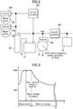
- FIG. 2 is a block diagram showing the configuration of a power source of the vehicle drive system 10 according to the first embodiment.
- FIG. 3 is a chart schematically showing one example of a change in voltage when regenerative electric power is charged to the capacitor 22, in the vehicle drive system 10 according to the first embodiment.
- FIG. 4 is a chart showing a relationship between a vehicle speed and a power output of each of the motors used in the vehicle drive system 10 according to the first embodiment.
- the configuration of a power source of the vehicle drive system 10 will be described.
- the battery 18 and the capacitor 22 provided in the vehicle drive system 10 are connected in series.
- the primary drive motor 16 is driven at about 48 V which is a reference output voltage of the battery 18, and each of the secondary drive motors 20 is driven at a voltage obtained by summing an output voltage of the battery 18 and an inter-terminal voltage (a voltage between terminals) of the capacitor 22, specifically, driven at a maximum voltage of 120 V which is greater than 48 V.
- the secondary drive motor 20 is always driven by electric power supplied through the capacitor 22.
- the inverter 16a is attached to the primary drive motor 16, and configured to convert DC power output from the battery 10 into AC power so as to enable the primary drive motor 16 composed of the permanent-magnetic electric motor to be driven by the AC power.
- the inverters 20a are attached, respectively, to the secondary drive motors 20, and configured to convert DC power output from the battery 18 and the capacitor 22 into AC power so as to enable the secondary drive motors 20 each composed of the induction electric motor to be driven by the AC power.
- a harness (not illustrated) for supplying electric power to the secondary drive motor 20 requires a high insulation property.
- an increase in weight of the harness due to the need to enhance the insulation property of the harness can be minimized, because each of the capacitors 22 is disposed in adjacent relation to a respective one of the secondary drive motors 20.
- each of the primary drive motor 16 and the secondary drive motors 20 functions as a generator to regenerate kinetic energy of the vehicle 1 so as to generate electric power.
- Regenerative electric power generated by the primary drive motor 16 is accumulated in the battery 18, and the regenerative electric power generated by the secondary drive motors 20 is accumulated in the capacitor 22.
- the high-voltage DC/DC converter 26a serving as a voltage converter is connected between the battery 18 and the capacitor 22.
- This high-voltage DC/DC converter 26a is operable, when electric charges accumulated in the capacitor 22 is insufficient (when the inter-terminal voltage of the capacitor 22 drops), to raise the voltage of the battery 18 to charge the capacity 22.
- the high-voltage DC/DC converter 26a is operable, when the inter-terminal voltage of the capacitor 22 rises to a given voltage or more, according to energy regeneration by the secondary drive motors 20, to apply electric power to the battery 18 while reducing electric charges accumulated in the capacitor 22, to charge the battery 18. That is, regenerative electric power generated by the secondary drive motors 20 is accumulated in the capacitor, and then a part of accumulated electric charges are charged to the battery 18 through the high-voltage DC/DC converter 26a.
- the low-voltage DC/DC converter 26b is connected between the battery 18 and a 12 V electric component of the vehicle 1.
- the controller 24 of the vehicle drive system 10 and most of electric components of the vehicle 1 operate at 12 V.
- the low-voltage DC/DC converter 26b is operable to reduce electric charges accumulated in the battery 18 to obtain a lowered voltage of 12 V, and supply the lowered voltage to the above components.
- the voltage of the capacitor 22 is a sum of a base voltage from the battery 18 and the inter-terminal voltage of the capacitor 22 itself.
- generation of regenerative electric power is performed by the secondary drive motors 20, and the regenerative electric power is charged to the capacitor 22.
- the inter-terminal voltage rises relatively rapidly.
- the high-voltage DC/DC converter 26a operates to charge the battery 18 while lowering the voltage of the capacitor 22.
- this charging from the capacitor 22 to the battery 18 is performed relatively gently as compared to the charging to the capacitor 22, so that the voltage of the capacitor 22 is lowered relatively gently to an adequate voltage.
- regenerative electric power generated by the secondary drive motors 20 is temporarily accumulated in the capacitor 22, and then gently charged to the battery 18. It should be noted here that, depending on a time period during which regeneration is performed, there is a possibility that the generation of regenerative electric power by the secondary drive motors 20 and the charging from the capacitor 22 to the battery 18 are performed in an overlapped manner.
- FIG. 4 is a chart showing the relationship between the vehicle speed of the vehicle 1 and the power output of each motor at each vehicle speed in the vehicle drive system 10 according to the first embodiment.
- a power output of the primary drive motor 16 is indicated by the broken line.
- a power output of one of the secondary drive motors 20 and a total of power outputs of the two secondary drive motors 20 are indicated, respectively, by the one-dot chain lime and the two-dot chain line, and a total of power outputs of all the motors is indicated by the solid line.
- the power output of the primary drive motor 16 is relatively large in a low vehicle speed range where a motor speed thereof is relatively low, and an outputtable value of the power output of the primary drive motor 16 gradually decreases as the vehicle speed becomes higher, as indicated by the broken line in FIG. 4 . That is, in this embodiment, the primary drive motor 16 is driven at about 48 V, wherein the primary drive motor 16 outputs a maximum torque of about 200 Nm until the motor speed thereof reaches about 1000 rpm, and, after the motor speed becomes greater than about 1000 rpm, the output torque gradually decreases along with an increase in the motor speed. In this embodiment, the primary drive motor 16 is configured to obtain a continuous power output of about 20 kW in the lowest motor speed range, and obtain a maximum power output of about 25 kW.
- the power output (total power output) of the secondary drive motor(s) 20 is extremely small in the low vehicle speed range, and gradually increases as the vehicle speed becomes higher to obtain the maximum power output at a vehicle speed of about 130 km/h, whereafter the power output (total power output) of the secondary drive motor(s) 20 gradually decreases, as indicated by the one-dot chain line and the two-dot chain line in FIG. 4 .
- each of the secondary drive motors 20 is configured to be driven at about 120 V, wherein, at a vehicle speed of about 130 km/h, a power output of about 17 kW is obtained in each of the secondary drive motors 20, and a power outputs of about 34 kW is obtained as a total power output of the two secondary drive motors 20. That is, in this embodiment, each of the secondary drive motors 20 has a torque curve in which a peak appears at a motor speed of about 600 to 800 rpm, and the maximum torque is obtained at about 200 Nm.
- the total of the power outputs of the primary drive motor 16 and the two secondary drive motors 20 is indicated by the solid line in FIG. 4 .
- a maximum power output of about 53 kW is obtained at a vehicle speed of about 130 km/h, and it is possible to satisfy a traveling condition required in the Worldwide Harmonized Light Vehicle Test Procedure (WLTP), by this maximum power output at this vehicle speed.
- WLTP Worldwide Harmonized Light Vehicle Test Procedure
- the vehicle when starting moving a vehicle and in the low vehicle speed range, the vehicle is driven only by the primary drive motor 16, and only when an relatively large power output is required in a high vehicle speed range (e.g., when the vehicle 1 is accelerated in the high vehicle speed range), the two secondary drive motors 20 generate power outputs.
- the induction electric motors capable of generating a relatively large power output in the high vehicle speed region, it is possible to obtain a sufficient power output when needed (e.g., during acceleration at a given vehicle speed or more), while keeping down an increase in vehicle weight.
- FIG. 5 is a sectional view schematically showing the structure of the secondary electric drive motor 20.
- the secondary drive motor 20 is an outer rotor-type induction electric motor which comprises a stator 28, and a rotor 30 rotatable around the stator 28.
- the stator 28 comprises: an approximately circular disk-shaped stator base 28a; a stator shaft 28b extending from the center of the stator base 28a; and a stator coil 28c attached around the stator shaft 28b.
- the stator coil 28c is housed in an electrically-insulating liquid chamber 32, such that it is immersed in electrically-insulating liquid 32a and subjected to ebullient cooling using the electrically-insulating liquid 32a.
- the rotor 30 is formed in an approximately circular tube shape, such that it surrounds around the stator 28.
- the rotor 30 comprises a rotor body 30a formed in an approximately circular tube shape whose one end is closed, and a rotor coil 30b disposed on an inner peripheral wall of the rotor body 30a.
- the rotor coil 30b is disposed in opposed relation to the stator coil 28c, such that an inductive current is generated therein by a rotating magnetic field formed in the stator coil 28c.
- the rotor 30 is supported by a bearing 34 attached to a distal end of the stator shaft 28b, such that it is smoothly rotated around the stator 28.
- the stator base 28a is supported by the upper arm and the lower arm (not illustrated) suspending the front wheel of the vehicle 1.
- the rotor body 30a is directly fixed to the wheel body (not illustrated) of the front wheel 2b.
- An alternating current converted by the inverter 20a is supplied to the stator coil 28c to form a rotating magnetic field therein.
- This rotating magnetic field causes an inductive current to flow through the rotor coil 30b, thereby generating a drive force for rotating the rotor body 30a.
- the drive force generated by each of the secondary drive motors 20 in the above manner rotationally drives the wheel body (not illustrated) of a corresponding one of the front wheels 2b.
- FIG. 6 is a sectional view for schematically explaining the principle of operation of the transmission 15 composed of a stepped variable transmission and provided in the vehicle drive system 10 according to the first embodiment.
- the transmission 15 employed in the vehicle drive system 10 according to this embodiment is a 6-speed stepped variable transmission.
- a mechanism for shifting from a certain low speed stage to a next higher speed stage and the function thereof will be exemplarily described. Based on the same configuration, shifting from a low speed stage side to a high speed stage side can be realized between any adjacent ones of the speed stages.
- the transmission 15 comprises: a main shaft 36 connected to an output shaft of the engine 12; a countershaft 38 serving as an output shaft of the transmission 15; a low speed-side gear set 40 (e.g., first speed gear set); and a high speed-side gear set 42 (e.g., second speed gear set) having a gear ratio less that that of the low speed-side gear set.
- the transmission 15 further comprises: a low speed-side dog clutch 44 provided in the main shaft 36; a high speed-side dog clutch 46; a first shift fork 48 for manipulating the low speed-side dog clutch 44; and a second shift fork 50 for manipulating the high speed-side dog clutch 50.
- the main shaft 36 is an input shaft of the transmission 15, and is connected to the output shaft of the engine 12 while being rotatably supported with respect to a transmission casing (not illustrated) of the transmission 15.
- the main shaft 36 is connected to the output shaft of the engine 12 through the propeller shaft 14a.
- the main shaft 36 may be directly connected to the output shaft of the engine 12.
- the countershaft 38 is the output shaft of the transmission 1, and is rotatably supported with respect to the transmission casing (not illustrated). Rotation of the countershaft 38 is transmitted to a differential gear unit (not illustrated) disposed in a rear portion of the vehicle 1 to drive the rear wheels 2a serving as a primary drive wheels.
- the low speed-side gear set 40 comprises a first gear 40a attached to the main shaft 36 and a second gear 40b attached to the countershaft 38, wherein the first and second gears 40a, 40b are always meshed with each other.
- the second gear 40b on the countershaft 38 is fixed to the countershaft 38, i.e., is configured to be always rotated together with the countershaft 38.
- the first gear 40a on the main shaft 36 is attached to the main shaft 36 in a freely rotatable manner (wherein the gear 40a is not slidable in an axial direction of the main shaft 36).
- the first gear 40a is configured to be capable of transmitting a drive force in a state in which it is fixed to the main shaft by the action of the low speed-side dog clutch 44.
- the high speed-side gear set 42 comprises a third gear 42a attached to the main shaft 36 and a fourth gear 42b attached to the countershaft 38, wherein the third and fourth gears 42a, 42b are always meshed with each other.
- the fourth gear 42b on the countershaft 38 is fixed to the countershaft 38, i.e., is configured to be always rotated together with the countershaft 38.
- the third gear 42a on the main shaft 36 is attached to the main shaft 36 in a freely rotatable manner, and configured to be capable of transmitting a drive force in a state in which it is fixed to the main shaft by the action of the high speed-side dog clutch 46.
- the low speed-side dog clutch 44 comprises a clutch cam ring 52 fixed to the main shaft 36, and a clutch ring 54 attached to an outer periphery of the clutch cam ring 52.
- the clutch cam ring 52 is a circular tube-shaped member, and is attached to an outer periphery of the main shaft 36, such that it is rotated integrally together with the main shaft 36. Further, an approximately axially-extending V-shaped cam groove 52a is provided plurally in an outer peripheral surface of the clutch cam ring 52 at even intervals in a circumferential direction of the main shaft 36.
- the clutch ring 54 is a doughnut-shaped circular plate disposed on the outer periphery of the clutch cam ring 52, and is attached to the clutch cam ring 52 in an axially slidable manner with respect to the clutch cam ring 52. Further, the clutch ring 54 has a plurality of cross-sectionally circular-shaped cam protrusions 54a provided on an inner periphery thereof at even intervals in the circumferential direction and each protruding radially inwardly from an inner periphery thereof. The cam protrusions 54a are received in a respective one of the cam grooves 52a provided in the outer periphery of the clutch cam ring 52. Based on the above configuration, when the clutch ring 54 is slid in the axial direction, the clutch ring 54 is also moved in the circumferential direction along the V-shaped cam grooves 52a provided in the clutch cam ring 52.
- the clutch ring 54 has a plurality of clutch teeth 54a provided on one of opposite lateral surfaces thereof and each protruding in the axial direction. Specifically, the clutch teeth 54d are formed in a lateral surface of the clutch ring 54 opposed to the first gear 40a at even intervals to extend in a radial pattern.
- the first gear 40a has a plurality of clutch teeth 40c provided on a lateral surface thereof opposed to the clutch ring 54 at even intervals to extend in a radial pattern.
- the clutch teeth 40c of the first gear 40a and the clutch teen 54b of the clutch ring 54 are formed such that they are engaged with each other when the clutch ring 54 is slid in the axial direction toward the first gear 40a.
- FIG. 6 shows a state in which the clutch ring 54 is slid to a position close to the first gear 40a, and the clutch teeth 40c and the clutch teeth 54b are engaged with each other.
- the high speed-side dog clutch 46 has a configuration similar to that of the low speed-side dog clutch 44, i.e., comprises a clutch cam ring 56 fixed to the main shaft 36, and a clutch ring 58 attached to an outer periphery of the clutch cam ring 56.
- the clutch cam ring 56 is a circular tube-shaped member, and an approximately axially-extending V-shaped cam groove 56a is provided plurally in an outer peripheral surface of the clutch cam ring 56 at even intervals in the circumferential direction.
- the clutch ring 58 is a doughnut-shaped circular plate disposed on the outer periphery of the clutch cam ring 52, and has a plurality of cross-sectionally circular-shaped cam protrusions 58a provided on an inner periphery thereof at even intervals in the circumferential direction and each protruding radially inwardly from an inner periphery thereof.
- the cam protrusions 58a are received in a respective one of the cam grooves 56a provided in the outer periphery of the clutch cam ring 56, whereby, when the clutch ring 58 is slid in the axial direction, the clutch ring 58 is also moved in the circumferential direction along the V-shaped cam grooves 56a.
- the clutch ring 58 has a plurality of clutch teeth 58b provided on one of opposite lateral surfaces thereof and each protruding in the axial direction.
- the third gear 42a has a plurality of clutch teeth 42c provided on a lateral surface thereof opposed to the clutch ring 58 at even intervals to extend in a radial pattern.
- the clutch teeth 42c of the third gear 42a and the clutch teen 58b of the clutch ring 58 are formed such that they are engaged with each other, and, in the engaged state, rotation of the third gear 42a with respect to the main shaft 36 is stopped to enable the high speed-side gear set 42 (third and fourth gears 42a, 42b) to transmit a drive force therethrough.
- FIG. 6 shows a state in which the clutch ring 58 is slid to a position away from the third gear 42a, and the engagement between the clutch teeth 42c and the clutch teeth 58b are released.
- Each of the first and second shift fork 48, 50 is provided to be movable in the axial direction of the main shaft 36 (horizontal direction in FIG. 6 ) along a respective one of two grooves (not illustrated) provided in an outer peripheral surface of a cylindrical shift drum (not illustrated).
- a shift dram (not illustrated) is rotated by an actuator (not illustrated)
- each of the first and second shift fork 48, 50 is moved in a given pattern according to a corresponding one of the grooves formed on the shift drum (not illustrated) to switch the gear engagement state.
- the speed stage shifting in the transmission 15 is automatically performed such that the controller 24 controls the actuator (not illustrated) to rotate the shift drum (not illustrated) to move each of the shift forks.
- the transmission 15 is configured to be operated in a mode in which one of the speed stage is automatically selected and set by the controller 24 according to the engine speed of the engine 12, the vehicle speed of the vehicle 1, etc. (automatic mode) or in a mode in which one of the speed stage is manually selected by a driver (manual mode).
- FIG. 6 shows the state in which a drive force is transmitted through the low speed-side gear set 40, and the third gear 42a of the high speed-side gear set 42 is freely rotated with respect to the main shaft 36.
- the first and second shift forks 48, 50 are moved, respectively, along the grooves provided on the shift drum (not illustrated). That is, when shifting the transmission 15 to a higher speed stage side, the first shift fork 48 is moved away from the first gear 40a, and the second shift fork 50 is moved close to the third gear 42a.
- This change in rotational speed causes a slight difference in rotational speed between the clutch cam ring 52 and the clutch ring 54.
- an inclined surface of the V-shaped cam groove 52a formed on the clutch cam ring 52 presses the cam protrusions 54a of the clutch ring 54.
- a component of the pressing force of the inclined surface of the cam groove 52a against the cam protrusions 54a is applied in a direction causing the clutch teeth 54d to be disengaged from the clutch teeth 40c and causing the clutch ring 54 to be moved away from the first gear 40a.
- the clutch teeth 58 of the clutch ring 58 and the clutch teeth 42c of the third gear 42a are engaged with each other, so that a drive force is transmitted through the high speed-side gear set 42.
- a gear to be selectively engaged is disposed on only one side of each of the clutch rings.
- the transmission may be configured such that clutch teeth are provided on both sides of each of the clutch rings, and a gear to be selectively engaged is disposed on both sides of each of the clutch rings. This makes it possible to provide a large number of speed stages in a compact configuration.
- FIG. 7 is a time chart showing one example of operations in the two modes.
- the time chart of FIG. 7 shows the vehicle speed of the vehicle 1, the torque generated by the engine 12, the torque generated by the primary drive motor 16, the torque generated by the secondary drive motors 20, the voltage of the capacitor 22, the current of the capacitor 22, and the current of the battery 18, in this order from the upper side of the drawing sheet.
- a positive value means a state in which each of the motors is generating a torque
- a negative value means a state in which each of the motors is regenerating kinetic energy of the vehicle 1.
- a negative value means a state in which each of the motors is supplying (discharging) regenerative electric power
- a positive value means a state in which each of the motors is charging regenerative electric power
- a driver starts moving the vehicle 1 and accelerates the vehicle 1, in the electric motor-based traveling mode.
- the primary drive motor 16 generates a torque, and the vehicle speed is increased (in a time period between times t 1 to t 2 in FIG. 10 ).
- a discharging current flows from the battery 18b supplying electric power to the primary drive motor 16, whereas the secondary drive motors 20 is kept from generating torque, so that a discharging current from the capacitor 22 is maintained at zero, and the voltage of the capacitor 22 is not changed.
- the traveling mode is set to the electric motor-based traveling mode, so that the engine 12 is not driven (no fuel is supplied to the engine 12, and thus no torque is generated by the engine 12).
- the vehicle 1 is driven to travel at a constant vehicle speed, until time t 3 . Then, when the driver manipulates a brake pedal (not illustrated) of the vehicle 1 at the time t 3 , driving by the primary drive motor 16 is stopped (no torque is generated by the primary drive motor 16), and kinetic energy of the vehicle 1 is regenerated as electric power by the secondary drive motors 20. Due to the regeneration of kinetic energy, the vehicle 1 is decelerated, and the discharging current from the battery 18 becomes zero. On the other hand, due to generation of regenerative electric power by the secondary drive motors 20, a charging current flows to the capacitor 22, and the voltage of the capacitor 22 is increased.
- the controller 24 operates to send a signal to the high-voltage DC/DC converter 26a to charge the capacitor 22.
- the high-voltage DC/DC converter 26a charges the capacitor 22 while increasing electric charges accumulated in the battery 18.
- a current for driving the primary drive motor 16 and a current for charging the capacitor 22 are discharged from the battery 18.
- the controller 24 operates to send a signal to the high-voltage DC/DC converter 26a to charge the battery 18 while lowering the voltage of the capacitor 22.
- regenerative electric power generated by the secondary drive motors 20 is consumed by the secondary drive motors 20, or is accumulated in the capacitor 22 once and then charged to the battery 18 through the high-voltage DC/DC converter 26a.
- the driver manipulates a switch (not illustrated) to switch the traveling mode of the vehicle 1 from the electric motor-based traveling mode to the internal combustion engine-based traveling mode, and depresses the accelerator pedal (not illustrated).
- a switch not illustrated
- the traveling mode of the vehicle 1 is switched to the internal combustion engine-based traveling mode
- supply of fuel to the engine 12 is initiated, so that the engine 12 starts to generate a torque.
- the output shaft (not illustrated) of the engine 12 is directly connected to an output shaft (not illustrated) of the primary drive motor 16, so that the output shaft of the engine 12 is always rotated in conjunction with driving of the primary drive motor 16.
- the electric motor-based traveling mode no fuel is supplied to the engine 12, and therefore no torque is generated by the engine 12.
- the engine 12 can generate a torque only after the fuel supply is initiated in the internal combustion engine-based traveling mode.
- the controller 24 operates to cause the primary drive motor 16 to generate an engine starting torque (in a time period between times t 12 to t 13 in FIG. 17).
- This engine starting torque is generated to enable the vehicle 1 to travel in a time period after initiation of the fuel supply to the engine 12 through until the engine 12 actually generate a torque, and suppress variation in torque before an after the torque generation by the engine 12.
- the fuel supply to the engine 12 is not initiated in a situation where the engine speed of the engine 12 is less than a given value at a time when the traveling mode is switched to the internal combustion engine-based traveling mode, but initiated at a time when the engine speed of the engine 12 is increased to the given value or more by the engine starting torque. Specifically, in this embodiment, the fuel supply is initiated when the engine speed of the engine 12 is increased to 2000 rpm or more.
- the controller 24 operates to drive the secondary drive motors 20 during shifting (speed stage shifting) of the transmission 15 composed of a stepped variable transmission, to execute torque adjustment control.
- a torque to be generated by this torque adjustment control is intended to instantaneously compensate for torque drop or the like, but does not fall under the same category of a torque for driving the vehicle 1. The details of the torque adjustment control will be described later.
- the controller 24 when the vehicle 1 is stopped at time t 15 , the controller 24 operates to supply a minimum amount of fuel necessary to maintain an idling operation of the engine 12. Further, the controller 24 operates to cause the primary drive motor 16 to generate an assist torque so as to enable the engine 12 to maintain the idling operation at a low engine speed.
- the engine 12 is a flywheel-less engine
- the assist torque generated by the primary drive motor 16 acts as a quasi-flywheel, so that the engine 12 can maintain a smooth idling operation at a low engine speed.
- the flywheel-less engine it is possible to obtain a high responsiveness of the engine 12 during traveling in the internal combustion engine-based traveling mode, whereby the driver can enjoy good feeling of vehicle manipulation.
- FIG. 8 is a graph schematically showing the acceleration of the vehicle 1 when the transmission 15 is shifted to the higher speed stage side (up-shifted), wherein the horizontal axis represents time [sec], and the vertical axis represents acceleration [m/s 2 ].
- FIGS. 9 and 10 are graphs each schematically showing the acceleration of the vehicle 1 when the transmission 15 is shifted to the lower speed stage side (down-shifted), wherein the horizontal axis represents time [sec], and the vertical axis represents acceleration [m/s 2 ].
- FIG. 8 shows a change in acceleration of the vehicle 1 when the transmission 15 is shifted from a first speed stage to a second speed stage in a state in which the accelerator pedal (not illustrated) of the vehicle 1 is depressed maximally.
- the acceleration of the vehicle 1 before the speed stage shifting is G1 [m/s 2 ].
- the speed storage shifting requires a time period of about 300 to 800 [msec] (in the example in FIG. 8 , about 500 [msec]), as indicated by the broken line in FIG. 8 . In this time period, the vehicle acceleration is lowered to about 0G, which gives a passenger the "feeling of acceleration drop", causing discomfort.
- a seamless-shift transmission configured such that a drive force is not substantially interrupted during the shifting to the higher speed stage side is employed as the stepped variable transmission 15, so that lowering of the acceleration during the speed stage shifting is suppressed, as indicated by the solid line in FIG. 8 .
- an amount of the acceleration drop during the speed stage shifting is reduced to ⁇ % or less with respect to the acceleration G1 before the speed stage shifting. This acceleration drop during the speed stage shifting, i.e., about ⁇ %, is sufficient to fulfill performance of a sporty vehicle, and is almost free from giving a passenger the "feeling of acceleration drop".
- FIG. 9 shows a change in acceleration of the vehicle 1 when the transmission 15 is shifted from a third speed stage to the second speed stage in a state in which the accelerator pedal (not illustrated) of the vehicle 1 is depressed.
- the transmission 15 is shifted to the lower speed stage side (down-shifted).
- the acceleration of the vehicle 1 before the speed stage shifting is G2 [m/s 2 ].
- the speed storage shifting requires a time period of about 300 to 1000 [msec] (in the example in FIG. 9 , about 600 [msec]), as indicated by the broken line in FIG. 9 .
- the vehicle acceleration is lowered to about 0G, which gives a passenger the "feeling of acceleration drop", causing discomfort.
- the seamless-shift transmission is employed as the stepped variable transmission 15, drive force interruption occurs during the shifting to the lower speed stage side (down-shifting). Therefore, in this embodiment, during the shifting to the lower speed stage side, the controller 24 operates to send a signal to the secondary drive motors 20 to generate a drive force, thereby compensating for the drive force drop (interruption). Specifically, in this embodiment, during the shifting of the transmission 15 to the lower speed stage side, the secondary drive motors 20 are controlled to generate a drive force to compensate for the drive force interruption during the speed stage shifting, as indicated by the solid line in FIG. 9 , thereby preventing acceleration drop. This makes it possible to obtain sufficient performance as a sporty vehicle, and become free from giving a passenger the "feeling of acceleration drop".
- the same level of acceleration drop as that of the auto shift manual-type transmission as indicated by the broken line in FIG. 9 is compensated for by a drive force of the secondary drive motors 20.
- a torque necessary to reduce the acceleration drop to ⁇ % or less with respect to the acceleration G2 before the speed stage shifting is ⁇ T2 [Nm].
- This torque ⁇ T2 is sufficiently smaller than the torque required during the shifting to the higher speed stage side as exemplified in FIG. 8 , so that the acceleration drop can be effectively compensated for by the relatively small-size secondary drive motors 20.
- drive force interruption in the primary drive wheels (rear wheels 2a) is compensated for by the secondary drive wheels (front wheels) using the secondary drive motors 20 which are in-wheel motors.
- the secondary drive motors 20 which are in-wheel motors.
- the drive force from the secondary drive motors 20 during the shifting of the transmission 15 to the lower speed stage side is generated for a significantly short time period, but is not substantially at a level capable of driving the vehicle 1. Therefore, a drive force to be generated by the secondary drive motors 20 can be produced by electric charges regenerated by the secondary drive motors 20 and accumulated in the capacitor 22.
- FIG. 10 shows a change in deceleration of the vehicle 1 when the transmission 15 is shifted from the third speed stage to the second speed stage in a state in which the accelerator pedal (not illustrated) of the vehicle 1 is not depressed, and the vehicle 1 is decelerated by engine brake.
- the acceleration of the vehicle 1 before the speed stage shifting is less than 0, and, in this state, the transmission 15 is shifted to the lower speed stage side.
- the speed storage shifting requires a time period of about 300 to 1000 [msec] (in the example in FIG. 10 , about 600 [msec]), as indicated by the broken line in FIG. 10 .
- the vehicle deceleration by engine brake becomes ineffective, so that the vehicle acceleration rises to about 0G, which gives a passenger the "feeling of free running", causing discomfort.
- the seamless-shift transmission is employed as the stepped variable transmission 15, engine brake becomes ineffective during the shifting to the lower speed stage side (down-shifting). Therefore, in this embodiment, during the shifting to the lower speed stage side, the controller 24 operates to send a signal to the secondary drive motors 20 to regenerate kinetic energy of the vehicle 1, thereby generating a brake force. Specifically, in this embodiment, when transmission 15 is shifted to the lower speed stage side, the secondary drive motors 20 during vehicle deceleration, the secondary drive motors 20 are controlled to regenerate the kinetic energy to compensate for the brake force interruption during the speed stage shifting, as indicated by the solid line in FIG. 10 , thereby preventing acceleration rise. This makes it possible to obtain sufficient performance as a sporty vehicle, and become free from giving a passenger the "feeling of free running".
- a brake force generated through the regenerative operation of the secondary drive motors 20 is suppressed by a brake force generated through the regenerative operation of the secondary drive motors 20.
- a braking torque necessary to obtain a brake force equal to that of normal engine brake is ⁇ T3 [Nm].
- This braking torque ⁇ T3 can be sufficiently obtained by the regenerative operation of the relatively small-size secondary drive motors 20 so as to effectively suppress the "feeling of free running".
- the controller 24 operates to cause the secondary drive motors 20 each serving as an assist motor to generate a drive force to compensate for drive force interruption during speed stage shifting ( FIG. 9 ), so that it is possible to suppress the "feeling of acceleration drop" which would otherwise be given to a passenger, thereby improving vehicle riding comfort.
- a seamless-shift transmission 15 configured such that a drive force is not substantially interrupted during shifting to the higher speed range side ( FIG. 6 ) is combined with the relatively small-size secondary drive motors 20 for compensating for drive force interruption during shifting to the lower speed stage side. This makes it possible to suppress the drive force interruption during speed stage shifting to provide good riding comfort of the vehicle 1, while avoiding deterioration in mobility performance of the vehicle 1 due to a significant increase in vehicle weight, and significant increase in cost.
- the vehicle drive system 10 comprises the primary drive motor 16 for generating a drive force for the rear wheels 2a each serving as a primary drive wheel, so that it is possible to realize the electric motor-based traveling mode in which a drive force of the engine 12 is not used ( FIG. 7 ).
- This makes it possible to drive the vehicle 1 to travel even in an area where traveling of the vehicle 1 by the engine 12 is restricted.
- the controller 24 operates to cause the secondary drive motors 20 to generate a drive force (the time t 9 in FIG. 7 ), so that it becomes possible to realize the electric motor-based traveling mode using a relatively small-size primary drive motor 16. This makes it possible to reduce the weight of the entire vehicle.
- each of the secondary drive motors 20 is an in-wheel motor ( FIG. 5 ).
- a generated drive force is directly transmitted to the front wheels, so that it is possible to instantaneously add the drive force to the vehicle 1 at a timing when the drive force interruption occurs. This makes it possible to more effectively suppress the feeling of acceleration drop which would otherwise be given to a passenger due to the drive force interruption.
- each of the secondary drive motors 20 is an in-wheel motor, and configured to drive a respective one of the front wheels 2b as secondary drive wheels, directly without changing the speed of a rotation output thereof ( FIG. 1 ), so that it is possible to eliminate a need to provide a mechanism for changing the speed of the rotation output of the secondary drive motor 20. This makes it possible to reduce the weight of the vehicle 1.
- the primary drive motor 16 does not generate any drive force in the internal combustion engine-based traveling mode ( FIG. 7 ), so that the vehicle 1 is driven based on a drive force generated by the engine 12.
- a driver can sufficiently enjoy a feeling of manipulation of the vehicle 1 which is driven to travel based on the engine 12.
- a drive force generated by the engine 12 disposed in the front portion of the vehicle 1 is transmitted to the rear wheels 2a so as to drive the rear wheels 2a, so that it is possible to enhance mobility performance of the vehicle 1.
- FIG. 11 is a layout diagram of a vehicle equipped with the vehicle drive system according to the second embodiment.
- the vehicle drive system according to the second embodiment is different from the vehicle drive system according to the first embodiment, in terms of a structure for transmitting a drive force generated by an engine, and the arrangement of a secondary drive motor.
- a part of the vehicle drive system according to the second embodiment different from the vehicle drive system according to the first embodiment will be described here.
- the common element or component is assigned with the same reference sign, and its description will be omitted.
- an engine 112 composed of an internal combustion engine is mounted to a front portion of the vehicle 100 at a position forward of a driver seat.
- the vehicle 100 is a so-called FR (Front Engine Rear Drive) vehicle configured such that a pair of right and left rear wheels 2a each serving as a primary drive wheel are driven by a drive force of the engine 112.
- FR Front Engine Rear Drive
- the rear wheels 2a are also driven by a primary drive motor 116 and a secondary drive motor 120.
- the vehicle drive system 110 according to the second embodiment equipped in the vehicle 100 comprises: the engine 112 for driving the rear wheels 2a; a transmission 115 composed of a stepped variable transmission; a primary drive motor 116 for driving the rear wheels 2a; a battery 118; and a controller 124 serving as a motor control device.
- the vehicle drive system 110 further comprises a secondary drive motor 120 serving as an assist motor for driving the right and left rear wheels 2a, and a capacitor 122 disposed in the vicinity of the secondary drive motor 120.
- the engine 112 is an internal combustion engine for generating a drive force for the rear wheels 2a each serving as a primary drive wheel.
- a drive force of the engine 112 disposed in the front portion of the vehicle 100 is transmitted to the right and left rear wheels through the transmission 115, a propeller shaft 117a, a coupling 117b, and a rear differential gear unit 117c for the rear wheels.
- the transmission 115 is a stepped variable transmission configured to change a rotational speed of an output shaft of the engine 112 and output the changed rotational speed, and the output of the transmission 115 is transmitted to the right and rear wheels 2a through the propeller shaft 117a, the coupling 117b and the rear differential gear unit 117c.
- a seamless-shift transmission is employed which is configured such that a drive force to be transmitted therethrough is interrupted during shifting to a lower speed stage side, but not substantially interrupted during shifting to a higher speed stage side.
- the propeller shaft 117a is disposed to pass through a tunnel section which is formed in a central region of a lower portion of the vehicle 100 to extend in a longitudinal (forward-rearward) direction of the vehicle 100, and the coupling 117b is connected to a rear end of the propeller shaft 117a.
- the coupling 117b is configured to transmit a drive force input thereinto to the rear differential gear unit 117c.
- the primary drive motor 116 is an electric motor for generating a drive force for the primary drive wheels, and is disposed behind and in adjacent relation to the engine 112. Further, an inverter 116a is disposed inside the tunnel section of the vehicle 100. A DC voltage of the battery 118 is converted into an AC voltage by the inverter 115a, and the resulting AC voltage is supplied to the primary drive motor 116.
- the primary drive motor 116 is connected in series with the engine 112 as shown in FIG. 11 , so that a drive force generated by the primary drive motor 116 is also transmitted to the rear wheels 2a through the transmission 115.
- a 25 kW permanent-magnetic electric motor permanent magnet synchronous electric motor
- the battery 118 is an electric power accumulator for accumulating electric energy mainly for operating the primary drive motor 116.
- a 48V, 3.5 kWh lithium-ion battery (LIB) is used as the battery 118.
- the secondary drive motor 120 is provided to generate a drive force for the rear wheels 2a each serving as a primary drive wheel, and integrated with the coupling 117b and the rear differential gear unit 117c.
- the secondary drive motor 120 is an on-board motor provided on the side of a vehicle body of the vehicle 100, and a drive force generated by the secondary drive motor 120 is transmitted to the right and left rear wheels 2a through the rear differential gear unit 117c without going through the transmission 115.
- an inverter 120a for the secondary drive motor is provided to convert a direct current from the capacitor (CAP) 122 into an alternating current, and supply the resulting alternating current to the secondary drive motor 120.
- CAP capacitor
- the capacitor 122 is provided to accumulate regenerative electric power generated by the secondary drive motor 120. As shown in FIG. 11 , the capacitor 122 and the inverter 120a are disposed in adjacent relation to each other, in the vicinity of the coupling 117b, the rear differential gear unit 117c and the secondary drive motor 120 which are arranged in a widthwise central region of the vehicle 100.
- the capacitor 122 is connected in series with the battery 118, and electric power from the capacitor 122 is supplied to the secondary drive motor 120 through the inverter 120a and a wire harness 122a.
- the secondary drive motor 120 is driven at a voltage greater than an inter-terminal voltage of the battery 118.
- the capacitor 122 is configured to accumulate electric charges at a voltage greater than that of the battery 118.
- a high-voltage DC/DC converter 126a serving as a voltage converter is connected between the battery 118 and the capacitor 122. This high-voltage DC/DC converter 126a enables bidirectional charging between the battery 118 and the capacitor 122.
- a low-voltage DC/DC converter 126b is connected between the battery 118 and a 12 V electric component (not illustrated) of the vehicle 100, and is operable to reduce electric charges accumulated in the battery 118 to obtain a lowered voltage of 12 V, and supply the lowered voltage to the above component or the like.
- the controller 124 shown in FIG. 11 is configured to control the engine 112, the primary drive motor 116 and the secondary drive motor 120 to execute an electric motor-based traveling mode and an internal combustion engine-based traveling mode. Further, the controller 124 is configured to cause the secondary drive motor 120 to generate a drive force during the shifting of the transmission 115 to the lower speed stage side, to compensate for the drive force interruption during the speed stage shifting.
- the controller 124 may comprise a microprocessor, a memory, an interface circuit, and a program for operating them (which are not illustrated).
- the vehicle drive system 110 is configured as above, so that a driving force generated by the secondary drive motor 120 serving as an assist motor is applied to the rear wheels 2a each serving as a primary drive wheel without going through the transmission 115.
- the secondary drive motor 120 is disposed downstream of the transmission 115 in a drive force transmission line extending from the engine 112, so that it can drive the rear wheels 2a without going through the transmission 115. Therefore, as with the vehicle drive system 10 according to the first embodiment, the drive force interruption due to the transmission 115 can be compensated for by causing the secondary drive motor 120 to generate a drive force during shifting to the lower speed stage side.
- the drive force interruption during the speed stage shifting can be compensated for by driving the rear wheels 2a each serving as a primary drive wheel based on a driving force of the secondary drive motor 120 serving as an assist motor. That is, in the vehicle drive system 110 according to the second embodiment, the driving force of the secondary drive motor 120 serving as an assist motor is applied to the primary drive wheels together with a driving force of the engine 112. However, the driving force of the secondary drive motor 120 is applied to a downstream side of the transmission 115 without going through the transmission 115, so that it can compensate for the drive force interruption in the transmission 115.
- the vehicle drive system has been applied to an FR vehicle.
- the present invention may be applied to various types of vehicles, such as a so-called FF vehicle in which an engine is disposed in a front portion of the vehicle, and each front wheel serves as a primary drive wheel, and a so-called RR vehicle in which an engine is disposed in a rear portion of the vehicle, and each rear wheel serves as a primary drive wheel.
- the vehicle drive system comprises a primary drive motor for driving a primary drive wheel.
- the present invention may be applied to a vehicle drive system devoid of the primary drive motor.
- an in-wheel motor is employed as the assist motor (secondary drive motor 20) to drive a secondary drive wheel.
- the vehicle drive system of the present invention may be configured to drive the secondary drive wheel by an on-board motor to compensate for the drive force interruption.
- an on-board motor is employed as the assist motor (secondary drive motor 120) to drive a primary drive wheel.
- the vehicle drive system of the present invention may be configured to drive the primary drive wheel by an in-wheel motor to compensate for the drive force interruption.
Landscapes
- Engineering & Computer Science (AREA)
- Mechanical Engineering (AREA)
- Chemical & Material Sciences (AREA)
- Combustion & Propulsion (AREA)
- Transportation (AREA)
- General Engineering & Computer Science (AREA)
- Automation & Control Theory (AREA)
- Electric Propulsion And Braking For Vehicles (AREA)
- Hybrid Electric Vehicles (AREA)
- Arrangement Or Mounting Of Propulsion Units For Vehicles (AREA)
- Control Of Driving Devices And Active Controlling Of Vehicle (AREA)
- Structure Of Transmissions (AREA)
Abstract
Description
- The present invention relates to a vehicle drive system, and more particularly to a vehicle drive system for driving a vehicle using an internal combustion engine.
- In
JP 2003-287088A - Patent Document 1:
JP 2003-287088A - However, in the automatic transmission provided by using a gear-type manual transmission as a basic structure thereof and modifying it to automate the speed stage shifting operation, as described in the
Patent Document 1, there is a problem that a drive force to be transmitted is unavoidably interrupted during speed stage shifting. That is, if the drive force is interrupted due to speed stage shifting in a state in which a vehicle is accelerated, a vehicle acceleration temporarily decreases, which gives a passenger a "feeling of acceleration drop", resulting in deteriorated vehicle riding comfort. On the other hand, if speed stage shifting is performed in a state in which the vehicle is decelerated, and an internal combustion engine acts as a brake, the vehicle acceleration temporality increases, which gives the passenger a "feeling of free running", resulting in deteriorated vehicle riding comfort. - It is therefore an object of the present invention to provide a vehicle drive system capable of, in a vehicle using a stepped (multistage) automatic transmission, suppressing the "feeling of acceleration drop" and the "feeling of free running" which would otherwise be given to a passenger during speed stage shifting, thereby improving vehicle riding comfort.
- In order to the above problem, the present invention provides a vehicle drive system for driving a vehicle using an internal combustion engine. The vehicle drive system comprises: an internal combustion engine configured to generate a drive force for driving a primary drive wheel of the vehicle; a stepped variable transmission connected to an output shaft of the internal combustion engine and configured to change a rotational speed of the output shaft of the internal combustion engine and output the changed rotational speed; an assist motor provided to apply a drive force to a secondary drive wheel of the vehicle, or apply a drive force to the primary drive wheel without going through the stepped variable transmission; and a motor control device configured to control a drive force to be output by the assist motor, wherein the stepped variable transmission is a seamless-shift transmission configured such that a drive force to be transmitted therethrough is interrupted during shifting down, but not substantially interrupted during shifting up, and the motor control device is operable, during the shifting down by the stepped variable transmission, to cause the assist motor to generate a drive force to compensate for the interruption of the drive force.
- In the vehicle drive system of the present invention having the above feature, the internal combustion engine is configured to generate a drive force for driving the primary drive wheel of the vehicle, and the stepped variable transmission is configured to change the rotational speed of the output shaft of the internal combustion engine and output the changed rotational speed. The stepped variable transmission is a seamless-shift transmission configured such that a drive force to be transmitted therethrough is interrupted during the shifting down, but not substantially interrupted during the shifting up. The assist motor is configured to apply a drive force to the secondary drive wheel, or apply a drive force to the primary drive wheel without going through the stepped variable transmission, and the motor control device is configured to control a drive force from the assist motor. The motor control device is operable, during the shifting down by the stepped variable transmission, to cause the assist motor to generate a drive force to compensate for the interruption of the drive force.
- According to this feature, the motor control device operates to cause the assist motor to generate a drive force to compensate for the drive force interruption during the shifting down, so that it is possible to suppress the "feeling of acceleration drop" which would otherwise be given to a passenger, thereby improving vehicle riding comfort. Here, a dual clutch transmission (DCT) has been known as a stepped variable transmission which is substantially free of occurrence of drive force interruption during speed stage shifting. However, the DCT has a structure in which two sets of torque transmission lines are switched by two clutches, so that the mechanism thereof becomes complicated, and the weight thereof becomes large. Thus, employing the DCT as a transmission gives rise to a problem of deterioration in vehicle mobility performance (acceleration performance, turning performance, etc.) due to the weight thereof, and increase in cost.
- It is also conceivable to use a commonly-used stepped variable transmission in which a drive force is interrupted during speed stage shifting, in combination with an electric motor, wherein the drive force interruption during speed stage shifting is compensated for by a drive force of the electric motor. However, in order to compensate for the drive force interruption occurring in a commonly-used stepped variable transmission, it is necessary to use a large-output electric motor capable of instantaneously generating a large torque. This gives rise to a problem that the electric motor is increased in terms of weight and cost.
- Comparing with this, a seamless-shift stepped variable transmission described in
JP 5707119B - The present inventor encountered the above problem has found that a large torque needs to compensate for drive force interruption occurring when a stepped variable transmission is shifted, in a normal traveling state, to the higher speed stage side (during up-shifting), whereas drive force interruption during the shifting to the lower speed stage side (down-shifting) can be compensated for by a relatively small drive force. Then, the present inventor has conceived of combining a seamless-shift transmission configured such that a drive force is not substantially interrupted during the shifting up, and a relatively small-size assist motor configured to compensate for the drive force interruption during the shifting down. This makes it possible to suppress the drive force interruption during speed stage shifting to provide good vehicle riding comfort, while avoiding deterioration in vehicle mobility performance due to a significant increase in vehicle weight, and significant increase in cost.
- Preferably, the vehicle drive system of the present invention further comprises a primary drive motor provided on a vehicle body of the vehicle and configured to generate a drive force for the primary drive wheel, wherein the motor control device is configured to be capable of executing an electric motor-based traveling mode in which the vehicle is driven to travel based on drive forces generated by the primary drive motor and the assist motor, wherein the motor control device is operable, only when accelerating the vehicle at a given vehicle speed or more, in the electric motor-based traveling mode, to cause the assist motor to generate a drive force.
- According to this feature, the vehicle drive system is equipped with the primary drive motor configured to generate a drive force for the primary drive wheel, so that it is possible to realize the electric motor-based traveling mode in which the drive force of the internal combustion engine is not used. This makes it possible to drive the vehicle to travel even in an area where traveling of the vehicle by the internal combustion engine is restricted. Further, when the vehicle is accelerated at a given vehicle speed or more, the motor control device operates to cause the assist motor to generate a drive force, so that it becomes possible to realize the electric motor-based traveling mode using a relatively small-size primary drive motor. This makes it possible to reduce the weight of the entire vehicle.
- Preferably, in the vehicle drive system of the present invention, the assist motor is an in-wheel motor provided in the primary drive wheel or the secondary drive wheel.
- According to this feature, the assist motor is an in-wheel motor. Thus, a generated drive force is directly transmitted to the drive wheel, so that it is possible to instantaneously add the drive force to the vehicle at a timing when the drive force interruption occurs. This makes it possible to more effectively suppress the feeling of acceleration drop which would otherwise be given to a passenger due to the drive force interruption.
- Preferably, in the vehicle drive system of the present invention, the assist motor is provided to drive the secondary drive wheel, directly without changing a speed of a rotation output thereof.
- According to this feature, the assist motor is configured to drive the secondary drive wheel, directly without changing the speed of the drive force output therefrom, so that it is possible to eliminate a need to provide a mechanism for changing the speed of the rotation output of the assist motor. This makes it possible to reduce the weight of the vehicle.
- Preferably, in the vehicle drive system of the present invention, the motor control device is configured to be capable of executing an internal combustion engine-based traveling mode in which the vehicle is driven to travel based on a drive force generated by the internal combustion engine, wherein the motor control device is operable, in the internal combustion engine-based traveling mode, to inhibit the primary drive motor from generating a drive force.
- According to this feature, in the internal combustion engine-based traveling mode, the primary drive motor does not generate any drive force, so that the vehicle is driven based on a drive force generated by the internal combustion engine. Thus, a driver can sufficiently enjoy a feeling of manipulation of the vehicle which is driven to travel based on the internal combustion engine.
- Preferably, the vehicle drive system of the present invention further comprises a drive force transmitting mechanism for transmitting a drive force generated by the internal combustion engine, wherein the internal combustion engine is disposed in a front portion of the vehicle, and wherein the drive force generated by the internal combustion engine is transmitted to a rear wheel as the primary drive wheel, through the drive force transmitting mechanism.
- According to this feature, the drive force generated by the internal combustion engine disposed in the front portion of the vehicle is transmitted to the rear wheel so as to drive the rear wheel, so that it is possible to enhance the vehicle mobility performance.
- The vehicle drive system of the present invention is capable of, in a vehicle using a stepped variable transmission, suppressing the "feeling of acceleration drop" and the "feeling of free running" which would otherwise be given to a passenger during speed stage shifting, thereby improving the vehicle riding comfort.
-
-
FIG. 1 is a layout diagram of a vehicle equipped with a vehicle drive system according to a first embodiment of the present invention. -
FIG. 2 is a block diagram showing the configuration of a power source of the vehicle drive system according to the first embodiment. -
FIG. 3 is a chart schematically showing one example of a change in voltage when regenerative electric power is charged to a capacitor, in the vehicle drive system according to the first embodiment. -
FIG. 4 is a chart showing a relationship between a vehicle speed and a power output of each motor used in the vehicle drive system according to the first embodiment. -
FIG. 5 is a sectional view schematically showing the structure of a secondary drive motor used in the vehicle drive system according to the first embodiment. -
FIG. 6 is a sectional view for schematically explaining the principle of operation of a transmission provided in the vehicle drive system according to the first embodiment. -
FIG. 7 is a time chart showing one example of operations in an electric motor-based traveling mode and an internal combustion engine-based traveling mode to be executed by a control device, in the vehicle drive system according to the first embodiment. -
FIG. 8 is a graph schematically showing a vehicle acceleration when a transmission is up-shifted, in the vehicle drive system according to the first embodiment. -
FIG. 9 is a graph schematically showing a vehicle acceleration when the transmission is down-shifted, in the vehicle drive system according to the first embodiment. -
FIG. 10 is a graph schematically showing a vehicle acceleration when the transmission is down-shifted, in the vehicle drive system according to the first embodiment. -
FIG. 11 is a layout diagram of a vehicle equipped with a vehicle drive system according to a second embodiment of the present invention. - With reference to accompanied drawings, a preferred embodiment of the present invention will now be described.
-
FIG. 1 is a layout diagram of a vehicle equipped with a vehicle drive system according to a first embodiment of the present invention. - As shown in
FIG. 1 , thevehicle 1 equipped with the vehicle drive system according to the first embodiment is a so-called "FR (Front engine, Rear drive) vehicle" in which anengine 12 composed of an internal combustion engine is provided in a front portion of the vehicle at a position forward of a driver seat, and configured to drive a pair of right and leftrear wheels 2a each serving as a primary drive wheel. As described later, thevehicle 1 is configured such that therear wheels 2a are also driven by a primary drive motor, i.e., a primary drive electric motor, and a pair of right and leftfront wheels 2b each serving as a secondary drive wheel are driven, respectively, by two secondary drive motors, i.e., secondary drive electric motors. - The
vehicle drive system 10 according to the first embodiment equipped in thevehicle 1 comprises: theengine 12 configured to drive therear wheels 2a; a driveforce transmitting mechanism 14 configured to transmit a drive force; aprimary drive motor 16 configured to drive therear wheels 2a; abattery 18 serving as an electric power accumulator; twosecondary drive motors 20 each serving as an assist motor configured to drive a respective one of thefront wheels 2b; acapacitor 22; and acontroller 24 as a motor control device. - The
engine 12 is an internal combustion engine for generating a drive force for therear wheels 2a as the primary drive wheel of thevehicle 1. In this embodiment, an in-line 4-cylinderr engine is employed as theengine 12, wherein theengine 12 is disposed in the front portion of thevehicle 1 and configured to drive therear wheels 2a through the driveforce transmitting mechanism 14. - The drive
force transmitting mechanism 14 is configured to transmit a drive force generated by theengine 12 to therear wheels 2a each serving as a primary drive wheel. The driveforce transmitting mechanism 14 comprises apropeller shaft 14a connected to theengine 12, a clutch 14b, and atransmission 15 composed of a stepped variable transmission. Thepropeller shaft 14a is disposed to extend from theengine 12 disposed in the front portion of thevehicle 1 toward a rear end of thevehicle 1 through a propeller shaft tunnel (not illustrated). A rear end of thepropeller shaft 14a is connected to thetransmission 15 via the clutch 14b. An output shaft of thetransmission 15 is connected to an axle (not illustrated) of therear wheels 2a so as to drive therear wheels 2a. - In this embodiment, as the
transmission 15, a seamless-shift transmission is employed which is configured such that a drive force to be transmitted therethrough is interrupted during shifting to a lower speed stage side, but not substantially interrupted during shifting to a higher speed stage side. Further, in this embodiment, thetransmission 15 is constructed as a so-called "rear transaxle arrangement". This allows the main body of the transmission having a large outer diameter to be removed from a position just behind theengine 12. Thus, the width of a floor tunnel (propeller shaft tunnel) can be reduced to ensure a central-side feet space of a passenger, so that it becomes possible to allow the lower body of the passenger to take an exactly forwardly-facing and bilaterally symmetric posture in a state in that the passenger sits on a seat. Further, it becomes easy to set the outer diameter and length of theprimary drive motor 16 to sufficient values depending on an intended power output, while ensuring the above passenger's posture. The details of thetransmission 15 will be described later. - The
primary drive motor 16 is an electric motor for generating a drive force for the primary drive wheels, and disposed behind and in adjacent relation to theengine 12. Further, an inverter (INV) 16a is disposed in adjacent relation to theprimary drive motor 16. Through theinverter 16a, a direct current from thebattery 18 is converted into an alternating current, and the converted current is supplied to theprimary drive motor 16. Theprimary drive motor 16 is connected in series with theengine 12, such that a drive force generated by theprimary drive motor 16 is also transmitted to therear wheels 2a through the driveforce transmitting mechanism 14. Alternatively, theprimary drive motor 16 may be connected to a halfway point of the driveforce transmitting mechanism 14, such that the drive force is transmitted to therear wheels 2a through a part of the driveforce transmitting mechanism 14. In this embodiment, as theprimary drive motor 16, a 25 kW permanent-magnetic electric motor (permanent magnet synchronous electric motor) is employed which is configured to be driven at 48 V. - The
battery 18 is an electric power accumulator for accumulating electric power mainly for operating theprimary drive motor 16. In this embodiment, thebattery 18 is received in the propeller shaft tunnel (not illustrated). In this embodiment, a 48V, 3.5 kWh lithium-ion battery (LIB) is used as thebattery 18. - In this embodiment, the rear transaxle arrangement is employed as mentioned above. Thus, a volume for receiving the
battery 18 can be expanded toward a front-side space of the floor tunnel (propeller shaft tunnel) formed as a result of the rear transaxle arrangement. This makes it possible to ensure and expand the receiving volume of thebattery 18 without narrowing the central-side space for a passenger due to an increase in width of the floor tunnel. - Each of the
secondary drive motors 20 is provided in a respective one of thefront wheels 2b as a so-called "unsprung portion" of thevehicle 1. In this embodiment, each of thefront wheels 2b is supported by a double wishbone suspension, i.e., suspended on a vehicle body of thevehicle 1 through upper arms, lower arms, a spring, and a shock absorber (which are not illustrated). Each of thesecondary drive motors 20 is an in-wheel motor (wheel motor), and received in a wheel body of a corresponding one of thefront wheels 2b. That is, each of thesecondary drive motors 20 is provided in the unsprung portion of thevehicle 1, and configured to drive a corresponding one of thefront wheels 2b. As shown inFIG. 1 , a direct current from the capacitor (CAP) 22 is converted into an alternating current through each of twoinverters 20a, and the converted current is supplied from theinverters 20a to thesecondary drive motors 20, respectively. Further, in this embodiment, no speed reducer is provided in each of thesecondary drive motors 20, so that a drive forcer of thesecondary drive motor 20 is directly transmitted to thefront wheel 2b. In this embodiment, a 17 kW induction electric motor is employed as each of thesecondary drive motors 20. - The capacitor (CAP) 22 is provided to accumulate regenerative electric power generated by the
secondary drive motors 20. Thecapacitor 22 is disposed just in front of theengine 12, and configured to supply electric power to thesecondary drive motors 20 each provided in a respective one of thefront wheels 2b of thevehicle 1. Thecapacitor 22 is configured to accumulate electric charges at a voltage greater than that of thebattery 18, and disposed within a region between the right and leftfront wheels 2b each serving as a secondary drive wheel. Each of thesecondary drive motors 20 to be driven mainly by electric power accumulated in thecapacitor 22 is driven at a voltage greater than that for theprimary drive motor 16. - The
controller 24 is configured to control theengine 12, theprimary drive motor 16 and thesecondary drive motors 20 to execute an electric motor-based traveling mode and an internal combustion engine-based traveling mode. Thecontroller 24 is also configured to control thetransmission 15 to change among a plurality of gear stages, and control thesecondary drive motors 20 to compensate for drive force interruption due to the speed stage shifting. Specifically, thecontroller 24 may comprise a microprocessor, a memory, an interface circuit, and a program for operating them (which are not illustrated). The details of the controller will be described later. - Further, as shown in
FIG. 1 , a high-voltage DC/DC converter 26a and a low-voltage DC/DC converter 26b each serving as a voltage converter are arranged in the vicinity of thecapacitor 22. The high-voltage DC/DC converter 26a, the low-voltage DC/DC converter 26b, thecapacitor 22 and theinverters 20a are unitized to form an integrated unit. - Next, with reference to
FIGS. 2 to 4 , the configuration of a power source of thevehicle drive system 10 according to the first embodiment and a state of drive of thevehicle 1 by the motors will be described. -
FIG. 2 is a block diagram showing the configuration of a power source of thevehicle drive system 10 according to the first embodiment.FIG. 3 is a chart schematically showing one example of a change in voltage when regenerative electric power is charged to thecapacitor 22, in thevehicle drive system 10 according to the first embodiment.FIG. 4 is a chart showing a relationship between a vehicle speed and a power output of each of the motors used in thevehicle drive system 10 according to the first embodiment. - Firstly, the configuration of a power source of the
vehicle drive system 10 according to the first embodiment will be described. As shown inFIG. 2 , thebattery 18 and thecapacitor 22 provided in thevehicle drive system 10 are connected in series. Theprimary drive motor 16 is driven at about 48 V which is a reference output voltage of thebattery 18, and each of thesecondary drive motors 20 is driven at a voltage obtained by summing an output voltage of thebattery 18 and an inter-terminal voltage (a voltage between terminals) of thecapacitor 22, specifically, driven at a maximum voltage of 120 V which is greater than 48 V. Thus, thesecondary drive motor 20 is always driven by electric power supplied through thecapacitor 22. - The
inverter 16a is attached to theprimary drive motor 16, and configured to convert DC power output from thebattery 10 into AC power so as to enable theprimary drive motor 16 composed of the permanent-magnetic electric motor to be driven by the AC power. Similarly, theinverters 20a are attached, respectively, to thesecondary drive motors 20, and configured to convert DC power output from thebattery 18 and thecapacitor 22 into AC power so as to enable thesecondary drive motors 20 each composed of the induction electric motor to be driven by the AC power. Here, since each of thesecondary drive motors 20 is driven at a voltage greater than that for theprimary drive motor 16, a harness (not illustrated) for supplying electric power to thesecondary drive motor 20 requires a high insulation property. However, an increase in weight of the harness due to the need to enhance the insulation property of the harness can be minimized, because each of thecapacitors 22 is disposed in adjacent relation to a respective one of thesecondary drive motors 20. - On the other hand, during deceleration or the like of the
vehicle 1, each of theprimary drive motor 16 and thesecondary drive motors 20 functions as a generator to regenerate kinetic energy of thevehicle 1 so as to generate electric power. Regenerative electric power generated by theprimary drive motor 16 is accumulated in thebattery 18, and the regenerative electric power generated by thesecondary drive motors 20 is accumulated in thecapacitor 22. - The high-voltage DC/
DC converter 26a serving as a voltage converter is connected between thebattery 18 and thecapacitor 22. This high-voltage DC/DC converter 26a is operable, when electric charges accumulated in thecapacitor 22 is insufficient (when the inter-terminal voltage of thecapacitor 22 drops), to raise the voltage of thebattery 18 to charge thecapacity 22. On the other hand, the high-voltage DC/DC converter 26a is operable, when the inter-terminal voltage of thecapacitor 22 rises to a given voltage or more, according to energy regeneration by thesecondary drive motors 20, to apply electric power to thebattery 18 while reducing electric charges accumulated in thecapacitor 22, to charge thebattery 18. That is, regenerative electric power generated by thesecondary drive motors 20 is accumulated in the capacitor, and then a part of accumulated electric charges are charged to thebattery 18 through the high-voltage DC/DC converter 26a. - The low-voltage DC/
DC converter 26b is connected between thebattery 18 and a 12 V electric component of thevehicle 1. Thecontroller 24 of thevehicle drive system 10 and most of electric components of thevehicle 1 operate at 12 V. The low-voltage DC/DC converter 26b is operable to reduce electric charges accumulated in thebattery 18 to obtain a lowered voltage of 12 V, and supply the lowered voltage to the above components. - Next, with reference to
FIG. 3 , charging and discharging with respect to thecapacitor 22 will be described. - As shown in
FIG. 3 , the voltage of thecapacitor 22 is a sum of a base voltage from thebattery 18 and the inter-terminal voltage of thecapacitor 22 itself. During deceleration or the like of thevehicle 1, generation of regenerative electric power is performed by thesecondary drive motors 20, and the regenerative electric power is charged to thecapacitor 22. In response to charging to thecapacitor 22, the inter-terminal voltage rises relatively rapidly. When the voltage of thecapacitor 22 rises to a given voltage or more as a result of the charging, the high-voltage DC/DC converter 26a operates to charge thebattery 18 while lowering the voltage of thecapacitor 22. As shown inFIG. 3 , this charging from thecapacitor 22 to thebattery 18 is performed relatively gently as compared to the charging to thecapacitor 22, so that the voltage of thecapacitor 22 is lowered relatively gently to an adequate voltage. - That is, regenerative electric power generated by the
secondary drive motors 20 is temporarily accumulated in thecapacitor 22, and then gently charged to thebattery 18. It should be noted here that, depending on a time period during which regeneration is performed, there is a possibility that the generation of regenerative electric power by thesecondary drive motors 20 and the charging from thecapacitor 22 to thebattery 18 are performed in an overlapped manner. - On the other hand, regenerative electric power generated by the
primary drive motor 16 is directly charged to thebattery 18. - Next, with reference to
FIG. 4 , a relationship between a vehicle speed and a power output of each motor in thevehicle drive system 10 according to the first embodiment will be described.FIG. 4 is a chart showing the relationship between the vehicle speed of thevehicle 1 and the power output of each motor at each vehicle speed in thevehicle drive system 10 according to the first embodiment. InFIG. 4 , a power output of theprimary drive motor 16 is indicated by the broken line. Further, a power output of one of thesecondary drive motors 20 and a total of power outputs of the twosecondary drive motors 20 are indicated, respectively, by the one-dot chain lime and the two-dot chain line, and a total of power outputs of all the motors is indicated by the solid line. - Since, the permanent-magnetic electric motor is employed as the
primary drive motor 16 in this embodiment, the power output of theprimary drive motor 16 is relatively large in a low vehicle speed range where a motor speed thereof is relatively low, and an outputtable value of the power output of theprimary drive motor 16 gradually decreases as the vehicle speed becomes higher, as indicated by the broken line inFIG. 4 . That is, in this embodiment, theprimary drive motor 16 is driven at about 48 V, wherein theprimary drive motor 16 outputs a maximum torque of about 200 Nm until the motor speed thereof reaches about 1000 rpm, and, after the motor speed becomes greater than about 1000 rpm, the output torque gradually decreases along with an increase in the motor speed. In this embodiment, theprimary drive motor 16 is configured to obtain a continuous power output of about 20 kW in the lowest motor speed range, and obtain a maximum power output of about 25 kW. - On the other hand, since the induction electric motor is employed as each of the
secondary drive motors 20, the power output (total power output) of the secondary drive motor(s) 20 is extremely small in the low vehicle speed range, and gradually increases as the vehicle speed becomes higher to obtain the maximum power output at a vehicle speed of about 130 km/h, whereafter the power output (total power output) of the secondary drive motor(s) 20 gradually decreases, as indicated by the one-dot chain line and the two-dot chain line inFIG. 4 . In this embodiment, each of thesecondary drive motors 20 is configured to be driven at about 120 V, wherein, at a vehicle speed of about 130 km/h, a power output of about 17 kW is obtained in each of thesecondary drive motors 20, and a power outputs of about 34 kW is obtained as a total power output of the twosecondary drive motors 20. That is, in this embodiment, each of thesecondary drive motors 20 has a torque curve in which a peak appears at a motor speed of about 600 to 800 rpm, and the maximum torque is obtained at about 200 Nm. - The total of the power outputs of the
primary drive motor 16 and the twosecondary drive motors 20 is indicated by the solid line inFIG. 4 . As is evident from this graph, in this embodiment, a maximum power output of about 53 kW is obtained at a vehicle speed of about 130 km/h, and it is possible to satisfy a traveling condition required in the Worldwide Harmonized Light Vehicle Test Procedure (WLTP), by this maximum power output at this vehicle speed. It should be noted here that although the power outputs of the twosecondary drive motors 20 are summed even in the low vehicle speed range as indicated by the solid line inFIG. 4 , thesecondary drive motors 20 are not actually driven in the low vehicle speed range. That is, when starting moving a vehicle and in the low vehicle speed range, the vehicle is driven only by theprimary drive motor 16, and only when an relatively large power output is required in a high vehicle speed range (e.g., when thevehicle 1 is accelerated in the high vehicle speed range), the twosecondary drive motors 20 generate power outputs. In this way, by using, only in the high vehicle speed region, the induction electric motors (secondary drive motors 20) capable of generating a relatively large power output in the high vehicle speed region, it is possible to obtain a sufficient power output when needed (e.g., during acceleration at a given vehicle speed or more), while keeping down an increase in vehicle weight. - Next, with reference to
FIG. 5 , the configuration of each of thesecondary drive motors 20 employed in thevehicle drive system 10 according to this embodiment will be described.FIG. 5 is a sectional view schematically showing the structure of the secondaryelectric drive motor 20. - As shown in
FIG. 5 , thesecondary drive motor 20 is an outer rotor-type induction electric motor which comprises astator 28, and arotor 30 rotatable around thestator 28. - The
stator 28 comprises: an approximately circular disk-shapedstator base 28a; astator shaft 28b extending from the center of thestator base 28a; and astator coil 28c attached around thestator shaft 28b. Thestator coil 28c is housed in an electrically-insulatingliquid chamber 32, such that it is immersed in electrically-insulatingliquid 32a and subjected to ebullient cooling using the electrically-insulatingliquid 32a. - The
rotor 30 is formed in an approximately circular tube shape, such that it surrounds around thestator 28. Therotor 30 comprises arotor body 30a formed in an approximately circular tube shape whose one end is closed, and arotor coil 30b disposed on an inner peripheral wall of therotor body 30a. Therotor coil 30b is disposed in opposed relation to thestator coil 28c, such that an inductive current is generated therein by a rotating magnetic field formed in thestator coil 28c. Further, therotor 30 is supported by a bearing 34 attached to a distal end of thestator shaft 28b, such that it is smoothly rotated around thestator 28. - The
stator base 28a is supported by the upper arm and the lower arm (not illustrated) suspending the front wheel of thevehicle 1. On the other hand, therotor body 30a is directly fixed to the wheel body (not illustrated) of thefront wheel 2b. An alternating current converted by theinverter 20a is supplied to thestator coil 28c to form a rotating magnetic field therein. This rotating magnetic field causes an inductive current to flow through therotor coil 30b, thereby generating a drive force for rotating therotor body 30a. The drive force generated by each of thesecondary drive motors 20 in the above manner rotationally drives the wheel body (not illustrated) of a corresponding one of thefront wheels 2b. - Next, with reference to
FIG. 6 , the configuration of thetransmission 15 will be described. -
FIG. 6 is a sectional view for schematically explaining the principle of operation of thetransmission 15 composed of a stepped variable transmission and provided in thevehicle drive system 10 according to the first embodiment. In this embodiment, thetransmission 15 employed in thevehicle drive system 10 according to this embodiment is a 6-speed stepped variable transmission. Here, for the sake of simplicity, a mechanism for shifting from a certain low speed stage to a next higher speed stage and the function thereof will be exemplarily described. Based on the same configuration, shifting from a low speed stage side to a high speed stage side can be realized between any adjacent ones of the speed stages. - As shown in
FIG. 6 , thetransmission 15 comprises: amain shaft 36 connected to an output shaft of theengine 12; acountershaft 38 serving as an output shaft of thetransmission 15; a low speed-side gear set 40 (e.g., first speed gear set); and a high speed-side gear set 42 (e.g., second speed gear set) having a gear ratio less that that of the low speed-side gear set. Thetransmission 15 further comprises: a low speed-side dog clutch 44 provided in themain shaft 36; a high speed-side dog clutch 46; afirst shift fork 48 for manipulating the low speed-side dog clutch 44; and asecond shift fork 50 for manipulating the high speed-side dog clutch 50. - The
main shaft 36 is an input shaft of thetransmission 15, and is connected to the output shaft of theengine 12 while being rotatably supported with respect to a transmission casing (not illustrated) of thetransmission 15. In this embodiment, themain shaft 36 is connected to the output shaft of theengine 12 through thepropeller shaft 14a. Alternatively, themain shaft 36 may be directly connected to the output shaft of theengine 12. - The
countershaft 38 is the output shaft of thetransmission 1, and is rotatably supported with respect to the transmission casing (not illustrated). Rotation of thecountershaft 38 is transmitted to a differential gear unit (not illustrated) disposed in a rear portion of thevehicle 1 to drive therear wheels 2a serving as a primary drive wheels. - The low speed-side gear set 40 comprises a
first gear 40a attached to themain shaft 36 and asecond gear 40b attached to thecountershaft 38, wherein the first andsecond gears second gear 40b on thecountershaft 38 is fixed to thecountershaft 38, i.e., is configured to be always rotated together with thecountershaft 38. On the other hand, thefirst gear 40a on themain shaft 36 is attached to themain shaft 36 in a freely rotatable manner (wherein thegear 40a is not slidable in an axial direction of the main shaft 36). Thefirst gear 40a is configured to be capable of transmitting a drive force in a state in which it is fixed to the main shaft by the action of the low speed-side dog clutch 44. - Similarly, the high speed-side gear set 42 comprises a
third gear 42a attached to themain shaft 36 and afourth gear 42b attached to thecountershaft 38, wherein the third andfourth gears fourth gear 42b on thecountershaft 38 is fixed to thecountershaft 38, i.e., is configured to be always rotated together with thecountershaft 38. On the other hand, thethird gear 42a on themain shaft 36 is attached to themain shaft 36 in a freely rotatable manner, and configured to be capable of transmitting a drive force in a state in which it is fixed to the main shaft by the action of the high speed-side dog clutch 46. - The low speed-
side dog clutch 44 comprises aclutch cam ring 52 fixed to themain shaft 36, and aclutch ring 54 attached to an outer periphery of theclutch cam ring 52. - The
clutch cam ring 52 is a circular tube-shaped member, and is attached to an outer periphery of themain shaft 36, such that it is rotated integrally together with themain shaft 36. Further, an approximately axially-extending V-shapedcam groove 52a is provided plurally in an outer peripheral surface of theclutch cam ring 52 at even intervals in a circumferential direction of themain shaft 36. - The
clutch ring 54 is a doughnut-shaped circular plate disposed on the outer periphery of theclutch cam ring 52, and is attached to theclutch cam ring 52 in an axially slidable manner with respect to theclutch cam ring 52. Further, theclutch ring 54 has a plurality of cross-sectionally circular-shapedcam protrusions 54a provided on an inner periphery thereof at even intervals in the circumferential direction and each protruding radially inwardly from an inner periphery thereof. Thecam protrusions 54a are received in a respective one of thecam grooves 52a provided in the outer periphery of theclutch cam ring 52. Based on the above configuration, when theclutch ring 54 is slid in the axial direction, theclutch ring 54 is also moved in the circumferential direction along the V-shapedcam grooves 52a provided in theclutch cam ring 52. - Further, the
clutch ring 54 has a plurality ofclutch teeth 54a provided on one of opposite lateral surfaces thereof and each protruding in the axial direction. Specifically, the clutch teeth 54d are formed in a lateral surface of theclutch ring 54 opposed to thefirst gear 40a at even intervals to extend in a radial pattern. On the other hand, thefirst gear 40a has a plurality ofclutch teeth 40c provided on a lateral surface thereof opposed to theclutch ring 54 at even intervals to extend in a radial pattern. Theclutch teeth 40c of thefirst gear 40a and theclutch teen 54b of theclutch ring 54 are formed such that they are engaged with each other when theclutch ring 54 is slid in the axial direction toward thefirst gear 40a. In a state in which theclutch teeth 40c and theclutch teeth 54b are engaged with each other, rotation of thefirst gear 40a with respect to themain shaft 36 is stopped to enable the low speed-side gear set 40 (first andsecond gears FIG. 6 shows a state in which theclutch ring 54 is slid to a position close to thefirst gear 40a, and theclutch teeth 40c and theclutch teeth 54b are engaged with each other. - An outer peripheral edge of the of the
clutch ring 54 is received in arecess 48a provided at a distal end of thefirst shift fork 48. Thus, according to a movement of thefirst shift fork 48, theclutch ring 54 is slid in the axial direction on theclutch cam ring 52 to switch between engagement and disengagement between theclutch ring 54 and thefirst gear 40a. - The high speed-
side dog clutch 46 has a configuration similar to that of the low speed-side dog clutch 44, i.e., comprises aclutch cam ring 56 fixed to themain shaft 36, and aclutch ring 58 attached to an outer periphery of theclutch cam ring 56. - The
clutch cam ring 56 is a circular tube-shaped member, and an approximately axially-extending V-shapedcam groove 56a is provided plurally in an outer peripheral surface of theclutch cam ring 56 at even intervals in the circumferential direction. - The
clutch ring 58 is a doughnut-shaped circular plate disposed on the outer periphery of theclutch cam ring 52, and has a plurality of cross-sectionally circular-shapedcam protrusions 58a provided on an inner periphery thereof at even intervals in the circumferential direction and each protruding radially inwardly from an inner periphery thereof. Thecam protrusions 58a are received in a respective one of thecam grooves 56a provided in the outer periphery of theclutch cam ring 56, whereby, when theclutch ring 58 is slid in the axial direction, theclutch ring 58 is also moved in the circumferential direction along the V-shapedcam grooves 56a. - Further, the
clutch ring 58 has a plurality ofclutch teeth 58b provided on one of opposite lateral surfaces thereof and each protruding in the axial direction. On the other hand, thethird gear 42a has a plurality ofclutch teeth 42c provided on a lateral surface thereof opposed to theclutch ring 58 at even intervals to extend in a radial pattern. Theclutch teeth 42c of thethird gear 42a and theclutch teen 58b of theclutch ring 58 are formed such that they are engaged with each other, and, in the engaged state, rotation of thethird gear 42a with respect to themain shaft 36 is stopped to enable the high speed-side gear set 42 (third andfourth gears FIG. 6 shows a state in which theclutch ring 58 is slid to a position away from thethird gear 42a, and the engagement between theclutch teeth 42c and theclutch teeth 58b are released. - An outer peripheral edge of the of the
clutch ring 58 is received in arecess 50a provided at a distal end of thesecond shift fork 50. Thus, according to a movement of thesecond shift fork 50, theclutch ring 58 is slid in the axial direction on theclutch cam ring 54 to switch between engagement and disengagement between theclutch ring 58 and thethird gear 42a. That is, according to respective movements of the first andsecond shift forks clutch ring 54 and thefirst gear 40a and between theclutch ring 58 and thethird gear 42a are switched. In this way, the drive force transmission through the low speed-side gear set 40 (first andsecond gears fourth gears - Each of the first and
second shift fork FIG. 6 ) along a respective one of two grooves (not illustrated) provided in an outer peripheral surface of a cylindrical shift drum (not illustrated). Thus, when the shift dram (not illustrated) is rotated by an actuator (not illustrated), each of the first andsecond shift fork - Next, speed stage shifting in the
transmission 15 will be described. - The speed stage shifting in the
transmission 15 is automatically performed such that thecontroller 24 controls the actuator (not illustrated) to rotate the shift drum (not illustrated) to move each of the shift forks. Thetransmission 15 is configured to be operated in a mode in which one of the speed stage is automatically selected and set by thecontroller 24 according to the engine speed of theengine 12, the vehicle speed of thevehicle 1, etc. (automatic mode) or in a mode in which one of the speed stage is manually selected by a driver (manual mode). - As mentioned above,
FIG. 6 shows the state in which a drive force is transmitted through the low speed-side gear set 40, and thethird gear 42a of the high speed-side gear set 42 is freely rotated with respect to themain shaft 36. In a case where the state in which a drive force is transmitted through the low speed-side gear set 40 is shifted to a state in which a drive force is transmitted through the high speed-side gear set 42 (up-shifting), the first andsecond shift forks transmission 15 to a higher speed stage side, thefirst shift fork 48 is moved away from thefirst gear 40a, and thesecond shift fork 50 is moved close to thethird gear 42a. - First of all, in the state in which a drive force is transmitted through the low speed-side gear set 40, the
clutch teeth 54b of theclutch ring 54 and theclutch teeth 40c of thefirst gear 40a are engaged with each other. In this state, themain shaft 36, thefirst gear 40a, theclutch cam ring 52 and theclutch ring 54 are rotated integrally at exactly the same rotational speed. Then, in order to shift thetransmission 15 to the higher speed stage side, theclutch ring 58 of the high speed-side dog clutch 46 is moved toward thethird gear 42a by thesecond shift fork 50. Thus, theclutch teeth 58a of theclutch ring 58 and theclutch teeth 42c of thethird gear 42c are brought into contact with each other, so that a drive force is also transmitted through the high speed-side gear set 42. Thus, a rotational speed of each of themain shaft 36 and thecountershaft 38 slightly changes. - This change in rotational speed causes a slight difference in rotational speed between the
clutch cam ring 52 and theclutch ring 54. Based on this difference in rotational speed, an inclined surface of the V-shapedcam groove 52a formed on theclutch cam ring 52 presses thecam protrusions 54a of theclutch ring 54. A component of the pressing force of the inclined surface of thecam groove 52a against thecam protrusions 54a is applied in a direction causing the clutch teeth 54d to be disengaged from theclutch teeth 40c and causing theclutch ring 54 to be moved away from thefirst gear 40a. Further, theclutch teeth 58 of theclutch ring 58 and theclutch teeth 42c of thethird gear 42a are engaged with each other, so that a drive force is transmitted through the high speed-side gear set 42. - In this way, the release of the engagement between the
clutch ring 54 and thefirst gear 40a based on the movement of thefirst shift fork 48, and the engagement between theclutch ring 58 and thesecond gear 42a based on the movement of thesecond shift fork 50 are approximately simultaneously performed. Therefore, shifting from the low speed-side gear set 40 to the high speed-side gear set 42 is instantaneously performed to complete the shifting to the high speed stage side in a state substantially free of drive force interruption. - In
FIG. 6 , a gear to be selectively engaged is disposed on only one side of each of the clutch rings. Alternatively, the transmission may be configured such that clutch teeth are provided on both sides of each of the clutch rings, and a gear to be selectively engaged is disposed on both sides of each of the clutch rings. This makes it possible to provide a large number of speed stages in a compact configuration. - Next, with reference to
FIG. 7 , operations of the electric motor-based traveling mode and the internal combustion engine-based traveling mode to be executed by thecontroller 24 will be described.FIG. 7 is a time chart showing one example of operations in the two modes. - The time chart of
FIG. 7 shows the vehicle speed of thevehicle 1, the torque generated by theengine 12, the torque generated by theprimary drive motor 16, the torque generated by thesecondary drive motors 20, the voltage of thecapacitor 22, the current of thecapacitor 22, and the current of thebattery 18, in this order from the upper side of the drawing sheet. In charts indicating the torque of theprimary drive motor 16 and the torque of thesecondary drive motors 20, a positive value means a state in which each of the motors is generating a torque, and a negative value means a state in which each of the motors is regenerating kinetic energy of thevehicle 1. Further, In charts indicating the current of thecapacitor 22 and the current of thebattery 18, a negative value means a state in which each of the motors is supplying (discharging) regenerative electric power, and a positive value means a state in which each of the motors is charging regenerative electric power. - First of all, in
FIG. 7 , at time t1, a driver starts moving thevehicle 1 and accelerates thevehicle 1, in the electric motor-based traveling mode. In this state, theprimary drive motor 16 generates a torque, and the vehicle speed is increased (in a time period between times t1 to t2 inFIG. 10 ). During this process, a discharging current flows from the battery 18b supplying electric power to theprimary drive motor 16, whereas thesecondary drive motors 20 is kept from generating torque, so that a discharging current from thecapacitor 22 is maintained at zero, and the voltage of thecapacitor 22 is not changed. Further, in the time period between the times t1 to t2, the traveling mode is set to the electric motor-based traveling mode, so that theengine 12 is not driven (no fuel is supplied to theengine 12, and thus no torque is generated by the engine 12). - In the example shown in
FIG. 7 , after thevehicle 1 is accelerated in the time period between the times t1 to t2, thevehicle 1 is driven to travel at a constant vehicle speed, until time t3. Then, when the driver manipulates a brake pedal (not illustrated) of thevehicle 1 at the time t3, driving by theprimary drive motor 16 is stopped (no torque is generated by the primary drive motor 16), and kinetic energy of thevehicle 1 is regenerated as electric power by thesecondary drive motors 20. Due to the regeneration of kinetic energy, thevehicle 1 is decelerated, and the discharging current from thebattery 18 becomes zero. On the other hand, due to generation of regenerative electric power by thesecondary drive motors 20, a charging current flows to thecapacitor 22, and the voltage of thecapacitor 22 is increased. - In
FIG. 7 , when thevehicle 1 is stopped at time t4, the charging current to thecapacitor 22 becomes zero, and the voltage of thecapacitor 22 becomes constant. Subsequently, thevehicle 1 is driven to start moving again at time t5, and reaches low vehicle speed traveling (time t6). Then, when deceleration of thevehicle 1 is started (time t7), generation of regenerative electric power is performed by thesecondary drive motors 20. As above, when staring moving and stopping are repeated at a relatively low vehicle speed in an urban area or the like, the traveling mode is set to the electric motor-based traveling mode in which thevehicle 1 purely functions as an electric vehicle (EV), i.e., no torque is generated by theengine 12. - Further, in
FIG. 7 , when thevehicle 1 is driven to start moving at time t8, thevehicle 1 is accelerated. Subsequently, when the vehicle speed of thevehicle 1 exceeds a given vehicle speed at time tg, thesecondary drive motors 20 are also driven. As above, when thevehicle 1 being traveling at a given vehicle speed or more is accelerated at a given acceleration or more in the electric motor-based traveling mode, electric power is supplied to theprimary drive motor 16 and thesecondary drive motors 20 to drive thevehicle 1 by these motors so as to obtain a required drive force. In this process, theprimary drive motor 16 is supplied with eclectic power from thebattery 18, and thesecondary drive motors 20 are supplied with eclectic power from thecapacitor 22. As a result of supplying electric power from thecapacitor 22 in the above manner, the voltage of thecapacitor 22 is lowered. - In
FIG. 7 , when thevehicle 1 transitions to traveling at a constant vehicle speed (when the amount of manipulation of an accelerator pedal becomes less than a given value) at time t10, the driving by thesecondary drive motors 20 is stopped (no torque is generated by the secondary drive motors 20), and thevehicle 1 is driven only by theprimary drive motor 16. As above, when thevehicle 1 is not accelerated at the given acceleration or more even in the state in which thevehicle 1 is traveling at the given vehicle speed or more, thevehicle 1 is driven only by theprimary drive motor 16. - Further, the voltage of the
capacitor 22 is lowered to a given value or less due to the driving of thesecondary drive motors 20 in the time period between the times t9 to t10. Thus, at the time t10, thecontroller 24 operates to send a signal to the high-voltage DC/DC converter 26a to charge thecapacitor 22. Specifically, the high-voltage DC/DC converter 26a charges thecapacitor 22 while increasing electric charges accumulated in thebattery 18. Thus, in a time period between times t10 to t11 inFIG. 7 , a current for driving theprimary drive motor 16 and a current for charging thecapacitor 22 are discharged from thebattery 18. Here, when large regenerative electric power is generated by thesecondary drive motors 20 and thus the voltage of thecapacitor 22 is increased to a given value or more, thecontroller 24 operates to send a signal to the high-voltage DC/DC converter 26a to charge thebattery 18 while lowering the voltage of thecapacitor 22. As above, regenerative electric power generated by thesecondary drive motors 20 is consumed by thesecondary drive motors 20, or is accumulated in thecapacitor 22 once and then charged to thebattery 18 through the high-voltage DC/DC converter 26a. - In
FIG. 7 , when thevehicle 1 is decelerated (a brake pedal is manipulated) at the time t11, kinetic energy of thevehicle 1 is regenerated as regenerative electric power by both theprimary drive motor 16 and thesecondary drive motors 20. Regenerative electric power generated by theprimary drive motor 16 is accumulated in thebattery 18, and Regenerative electric power generated by thesecondary drive motors 20 is accumulated by thecapacitor 22. As above, when the brake pedal is manipulated at the given vehicle speed or more, regenerative electric power is generated by both theprimary drive motor 16 and thesecondary drive motors 20, and resulting electric charges are accumulated in thebattery 18 and thecapacitor 22. - Then, in
FIG. 7 , at time t12, the driver manipulates a switch (not illustrated) to switch the traveling mode of thevehicle 1 from the electric motor-based traveling mode to the internal combustion engine-based traveling mode, and depresses the accelerator pedal (not illustrated). When the traveling mode of thevehicle 1 is switched to the internal combustion engine-based traveling mode, supply of fuel to theengine 12 is initiated, so that theengine 12 starts to generate a torque. Specifically, in this embodiment, the output shaft (not illustrated) of theengine 12 is directly connected to an output shaft (not illustrated) of theprimary drive motor 16, so that the output shaft of theengine 12 is always rotated in conjunction with driving of theprimary drive motor 16. However, in the electric motor-based traveling mode, no fuel is supplied to theengine 12, and therefore no torque is generated by theengine 12. Theengine 12 can generate a torque only after the fuel supply is initiated in the internal combustion engine-based traveling mode. - Further, just after the traveling mode is switched from the electric motor-based traveling mode to the internal combustion engine-based traveling mode, the
controller 24 operates to cause theprimary drive motor 16 to generate an engine starting torque (in a time period between times t12 to t13 in FIG. 17). This engine starting torque is generated to enable thevehicle 1 to travel in a time period after initiation of the fuel supply to theengine 12 through until theengine 12 actually generate a torque, and suppress variation in torque before an after the torque generation by theengine 12. Further, in this embodiment, the fuel supply to theengine 12 is not initiated in a situation where the engine speed of theengine 12 is less than a given value at a time when the traveling mode is switched to the internal combustion engine-based traveling mode, but initiated at a time when the engine speed of theengine 12 is increased to the given value or more by the engine starting torque. Specifically, in this embodiment, the fuel supply is initiated when the engine speed of theengine 12 is increased to 2000 rpm or more. - After start-up of the
engine 12, in the internal combustion engine-based traveling mode, a drive force for driving thevehicle 1 is entirely output from theengine 12, and theprimary drive motor 16 and thesecondary drive motors 20 never output a drive force for driving thevehicle 1. Thus, the driver can enjoy a feeling of manipulation of thevehicle 1 which is driven by the internal combustion engine. - Subsequently, when the driver manipulates the brake pedal (not illustrated) at time t14 in
FIG. 7 , the fuel supply to theengine 12 is stopped to suppress fuel consumption. Further, kinetic energy of thevehicle 1 is regenerated as electric energy by theprimary drive motor 16 and thesecondary drive motors 20, and a charging current flows to thebattery 18 and thecapacitor 22. - In a situation where the
vehicle 1 is being decelerated in the internal combustion engine-based traveling mode, thecontroller 24 operates to drive thesecondary drive motors 20 during shifting (speed stage shifting) of thetransmission 15 composed of a stepped variable transmission, to execute torque adjustment control. A torque to be generated by this torque adjustment control is intended to instantaneously compensate for torque drop or the like, but does not fall under the same category of a torque for driving thevehicle 1. The details of the torque adjustment control will be described later. - On the other hand, in
FIG. 1 , when thevehicle 1 is stopped at time t15, thecontroller 24 operates to supply a minimum amount of fuel necessary to maintain an idling operation of theengine 12. Further, thecontroller 24 operates to cause theprimary drive motor 16 to generate an assist torque so as to enable theengine 12 to maintain the idling operation at a low engine speed. - In this embodiment, although the
engine 12 is a flywheel-less engine, the assist torque generated by theprimary drive motor 16 acts as a quasi-flywheel, so that theengine 12 can maintain a smooth idling operation at a low engine speed. In addition, by employing the flywheel-less engine, it is possible to obtain a high responsiveness of theengine 12 during traveling in the internal combustion engine-based traveling mode, whereby the driver can enjoy good feeling of vehicle manipulation. - Further, when the
vehicle 1 is driven to start moving from a stopped state in the internal combustion engine-based traveling mode, thecontroller 24 operates to send a signal to theprimary drive motor 16 to increase the rotational speed of the primary drive motor 16 (= the engine speed of the engine 12) to a given value. After the engine speed is increased to the given value, thecontroller 24 operates to supply engine driving fuel to theengine 12 to cause theengine 12 to generate a drive force so as to enable traveling in the internal combustion engine-based traveling mode. - Next, with reference to
FIGS. 8 to 10 , a change in acceleration of the vehicle during shifting (speed stage shifting) of thetransmission 15 will be described. -
FIG. 8 is a graph schematically showing the acceleration of thevehicle 1 when thetransmission 15 is shifted to the higher speed stage side (up-shifted), wherein the horizontal axis represents time [sec], and the vertical axis represents acceleration [m/s2]. Similarly,FIGS. 9 and10 are graphs each schematically showing the acceleration of thevehicle 1 when thetransmission 15 is shifted to the lower speed stage side (down-shifted), wherein the horizontal axis represents time [sec], and the vertical axis represents acceleration [m/s2]. - Firstly,
FIG. 8 shows a change in acceleration of thevehicle 1 when thetransmission 15 is shifted from a first speed stage to a second speed stage in a state in which the accelerator pedal (not illustrated) of thevehicle 1 is depressed maximally. Here, in the example shown inFIG. 8 , the acceleration of thevehicle 1 before the speed stage shifting is G1 [m/s2]. In a conventional so-called auto shift manual (ASM)-type transmission configured to automatically shift a stepped manual automatic transmission by an actuator, the speed storage shifting requires a time period of about 300 to 800 [msec] (in the example inFIG. 8 , about 500 [msec]), as indicated by the broken line inFIG. 8 . In this time period, the vehicle acceleration is lowered to about 0G, which gives a passenger the "feeling of acceleration drop", causing discomfort. - Comparing this, in an automatic transmission equipped with a torque converter, drop of the acceleration during shifting from the first speed stage to the second speed stage is extremely small, as indicated by the one-dot chain line in
FIG. 8 , so that a passenger never has the "feeling of acceleration drop". - Further, in this embodiment, a seamless-shift transmission configured such that a drive force is not substantially interrupted during the shifting to the higher speed stage side is employed as the stepped
variable transmission 15, so that lowering of the acceleration during the speed stage shifting is suppressed, as indicated by the solid line inFIG. 8 . Specifically, in this embodiment, an amount of the acceleration drop during the speed stage shifting is reduced to α% or less with respect to the acceleration G1 before the speed stage shifting. This acceleration drop during the speed stage shifting, i.e., about α%, is sufficient to fulfill performance of a sporty vehicle, and is almost free from giving a passenger the "feeling of acceleration drop". - It is conceivable to suppress the acceleration drop as indicated by the broken line in
FIG. 8 in the conventional auto shift manual-type transmission, by using a drive force of an electric motor. In this case, in order to reduce the acceleration drop as indicated by the broken line inFIG. 8 , to the level of the acceleration drop as indicated by the solid line in thevehicle drive system 10 according top this embodiment, it is necessary to instantaneously compensate by a torque of about ΔT1 [Nm]. This motor torque ΔT1 necessary for the compensation is a large value equal to a torque necessary for an electric vehicle to travel by a single motor, so that a large-size motor is required for the compensation, thereby leading to a significant increase in weight. - Secondly,
FIG. 9 shows a change in acceleration of thevehicle 1 when thetransmission 15 is shifted from a third speed stage to the second speed stage in a state in which the accelerator pedal (not illustrated) of thevehicle 1 is depressed. Specifically, inFIG. 9 , in a situation where the accelerator pedal (not illustrated) of thevehicle 1 is depressed to accelerate thevehicle 1 from a given vehicle speed, such that the degree of depression of the accelerator pedal increases at a given rate, thetransmission 15 is shifted to the lower speed stage side (down-shifted). - Here, in the example shown in
FIG. 9 , the acceleration of thevehicle 1 before the speed stage shifting is G2 [m/s2]. In the conventional auto shift manual-type transmission, the speed storage shifting requires a time period of about 300 to 1000 [msec] (in the example inFIG. 9 , about 600 [msec]), as indicated by the broken line inFIG. 9 . In this time period, the vehicle acceleration is lowered to about 0G, which gives a passenger the "feeling of acceleration drop", causing discomfort. - Comparing this, in the automatic transmission equipped with a torque converter, drop of the acceleration during shifting from the third speed stage to the second speed stage is extremely small, as indicated by the one-dot chain line in
FIG. 9 , so that a passenger never has the "feeling of acceleration drop". - Here, in this embodiment, although the seamless-shift transmission is employed as the stepped
variable transmission 15, drive force interruption occurs during the shifting to the lower speed stage side (down-shifting). Therefore, in this embodiment, during the shifting to the lower speed stage side, thecontroller 24 operates to send a signal to thesecondary drive motors 20 to generate a drive force, thereby compensating for the drive force drop (interruption). Specifically, in this embodiment, during the shifting of thetransmission 15 to the lower speed stage side, thesecondary drive motors 20 are controlled to generate a drive force to compensate for the drive force interruption during the speed stage shifting, as indicated by the solid line inFIG. 9 , thereby preventing acceleration drop. This makes it possible to obtain sufficient performance as a sporty vehicle, and become free from giving a passenger the "feeling of acceleration drop". - As above, in this embodiment, the same level of acceleration drop as that of the auto shift manual-type transmission as indicated by the broken line in
FIG. 9 is compensated for by a drive force of thesecondary drive motors 20. Here, a torque necessary to reduce the acceleration drop to α% or less with respect to the acceleration G2 before the speed stage shifting is ΔT2 [Nm]. This torque ΔT2 is sufficiently smaller than the torque required during the shifting to the higher speed stage side as exemplified inFIG. 8 , so that the acceleration drop can be effectively compensated for by the relatively small-sizesecondary drive motors 20. - Further, in this embodiment, drive force interruption in the primary drive wheels (
rear wheels 2a) is compensated for by the secondary drive wheels (front wheels) using thesecondary drive motors 20 which are in-wheel motors. Thus, it is possible to compensate for the drive force interruption with a high responsiveness, without receiving an influence of dynamic properties of the driveforce transmitting mechanism 14 for transmitting a drive force to the primary drive wheels. The drive force from thesecondary drive motors 20 during the shifting of thetransmission 15 to the lower speed stage side is generated for a significantly short time period, but is not substantially at a level capable of driving thevehicle 1. Therefore, a drive force to be generated by thesecondary drive motors 20 can be produced by electric charges regenerated by thesecondary drive motors 20 and accumulated in thecapacitor 22. - Thirdly,
FIG. 10 shows a change in deceleration of thevehicle 1 when thetransmission 15 is shifted from the third speed stage to the second speed stage in a state in which the accelerator pedal (not illustrated) of thevehicle 1 is not depressed, and thevehicle 1 is decelerated by engine brake. In the example shown inFIG. 10 , the acceleration of thevehicle 1 before the speed stage shifting is less than 0, and, in this state, thetransmission 15 is shifted to the lower speed stage side. In the conventional auto shift manual-type transmission, the speed storage shifting requires a time period of about 300 to 1000 [msec] (in the example inFIG. 10 , about 600 [msec]), as indicated by the broken line inFIG. 10 . In this time period, the vehicle deceleration by engine brake becomes ineffective, so that the vehicle acceleration rises to about 0G, which gives a passenger the "feeling of free running", causing discomfort. - Comparing this, in the automatic transmission equipped with a torque converter, rise of the acceleration during shifting from the third speed stage to the second speed stage is extremely small, as indicated by the one-dot chain line in
FIG. 10 , so that a passenger never has the "feeling of free running". - Here, in this embodiment, although the seamless-shift transmission is employed as the stepped
variable transmission 15, engine brake becomes ineffective during the shifting to the lower speed stage side (down-shifting). Therefore, in this embodiment, during the shifting to the lower speed stage side, thecontroller 24 operates to send a signal to thesecondary drive motors 20 to regenerate kinetic energy of thevehicle 1, thereby generating a brake force. Specifically, in this embodiment, whentransmission 15 is shifted to the lower speed stage side, thesecondary drive motors 20 during vehicle deceleration, thesecondary drive motors 20 are controlled to regenerate the kinetic energy to compensate for the brake force interruption during the speed stage shifting, as indicated by the solid line inFIG. 10 , thereby preventing acceleration rise. This makes it possible to obtain sufficient performance as a sporty vehicle, and become free from giving a passenger the "feeling of free running". - As above, in this embodiment, the same level of acceleration rise as that of the auto shift manual-type transmission as indicated by the broken line in
FIG. 10 is suppressed by a brake force generated through the regenerative operation of thesecondary drive motors 20. Here, a braking torque necessary to obtain a brake force equal to that of normal engine brake is ΔT3 [Nm]. This braking torque ΔT3 can be sufficiently obtained by the regenerative operation of the relatively small-sizesecondary drive motors 20 so as to effectively suppress the "feeling of free running". - In the
vehicle drive system 10 according to the first embodiment, thecontroller 24 operates to cause thesecondary drive motors 20 each serving as an assist motor to generate a drive force to compensate for drive force interruption during speed stage shifting (FIG. 9 ), so that it is possible to suppress the "feeling of acceleration drop" which would otherwise be given to a passenger, thereby improving vehicle riding comfort. In thevehicle drive system 10 according to the first embodiment, a seamless-shift transmission 15 configured such that a drive force is not substantially interrupted during shifting to the higher speed range side (FIG. 6 ) is combined with the relatively small-sizesecondary drive motors 20 for compensating for drive force interruption during shifting to the lower speed stage side. This makes it possible to suppress the drive force interruption during speed stage shifting to provide good riding comfort of thevehicle 1, while avoiding deterioration in mobility performance of thevehicle 1 due to a significant increase in vehicle weight, and significant increase in cost. - The
vehicle drive system 10 according to the first embodiment comprises theprimary drive motor 16 for generating a drive force for therear wheels 2a each serving as a primary drive wheel, so that it is possible to realize the electric motor-based traveling mode in which a drive force of theengine 12 is not used (FIG. 7 ). This makes it possible to drive thevehicle 1 to travel even in an area where traveling of thevehicle 1 by theengine 12 is restricted. Further, when thevehicle 1 is accelerated at a given vehicle speed or more, thecontroller 24 operates to cause thesecondary drive motors 20 to generate a drive force (the time t9 inFIG. 7 ), so that it becomes possible to realize the electric motor-based traveling mode using a relatively small-sizeprimary drive motor 16. This makes it possible to reduce the weight of the entire vehicle. - In the
vehicle drive system 10 according to the first embodiment, each of thesecondary drive motors 20 is an in-wheel motor (FIG. 5 ). Thus, a generated drive force is directly transmitted to the front wheels, so that it is possible to instantaneously add the drive force to thevehicle 1 at a timing when the drive force interruption occurs. This makes it possible to more effectively suppress the feeling of acceleration drop which would otherwise be given to a passenger due to the drive force interruption. - In the
vehicle drive system 10 according to the first embodiment, each of thesecondary drive motors 20 is an in-wheel motor, and configured to drive a respective one of thefront wheels 2b as secondary drive wheels, directly without changing the speed of a rotation output thereof (FIG. 1 ), so that it is possible to eliminate a need to provide a mechanism for changing the speed of the rotation output of thesecondary drive motor 20. This makes it possible to reduce the weight of thevehicle 1. - In the
vehicle drive system 10 according to the first embodiment, theprimary drive motor 16 does not generate any drive force in the internal combustion engine-based traveling mode (FIG. 7 ), so that thevehicle 1 is driven based on a drive force generated by theengine 12. Thus, a driver can sufficiently enjoy a feeling of manipulation of thevehicle 1 which is driven to travel based on theengine 12. - In the
vehicle drive system 10 according to the first embodiment, a drive force generated by theengine 12 disposed in the front portion of thevehicle 1 is transmitted to therear wheels 2a so as to drive therear wheels 2a, so that it is possible to enhance mobility performance of thevehicle 1. - Next, with reference to
FIG. 11 , a vehicle drive system according to a second embodiment of the present invention will be described. -
FIG. 11 is a layout diagram of a vehicle equipped with the vehicle drive system according to the second embodiment. - The vehicle drive system according to the second embodiment is different from the vehicle drive system according to the first embodiment, in terms of a structure for transmitting a drive force generated by an engine, and the arrangement of a secondary drive motor. Thus, only a part of the vehicle drive system according to the second embodiment different from the vehicle drive system according to the first embodiment will be described here. Further, the common element or component is assigned with the same reference sign, and its description will be omitted.
- As shown in
FIG. 8 , in avehicle 100 equipped with thevehicle drive system 110 according to the second embodiment, anengine 112 composed of an internal combustion engine is mounted to a front portion of thevehicle 100 at a position forward of a driver seat. Thevehicle 100 is a so-called FR (Front Engine Rear Drive) vehicle configured such that a pair of right and leftrear wheels 2a each serving as a primary drive wheel are driven by a drive force of theengine 112. As will descried later, therear wheels 2a are also driven by aprimary drive motor 116 and asecondary drive motor 120. - The
vehicle drive system 110 according to the second embodiment equipped in thevehicle 100 comprises: theengine 112 for driving therear wheels 2a; atransmission 115 composed of a stepped variable transmission; aprimary drive motor 116 for driving therear wheels 2a; abattery 118; and acontroller 124 serving as a motor control device. Thevehicle drive system 110 further comprises asecondary drive motor 120 serving as an assist motor for driving the right and leftrear wheels 2a, and acapacitor 122 disposed in the vicinity of thesecondary drive motor 120. - The
engine 112 is an internal combustion engine for generating a drive force for therear wheels 2a each serving as a primary drive wheel. In the second embodiment, a drive force of theengine 112 disposed in the front portion of thevehicle 100 is transmitted to the right and left rear wheels through thetransmission 115, apropeller shaft 117a, acoupling 117b, and a reardifferential gear unit 117c for the rear wheels. - The
transmission 115 is a stepped variable transmission configured to change a rotational speed of an output shaft of theengine 112 and output the changed rotational speed, and the output of thetransmission 115 is transmitted to the right andrear wheels 2a through thepropeller shaft 117a, thecoupling 117b and the reardifferential gear unit 117c. In the second embodiment, as thetransmission 115, a seamless-shift transmission is employed which is configured such that a drive force to be transmitted therethrough is interrupted during shifting to a lower speed stage side, but not substantially interrupted during shifting to a higher speed stage side. Thepropeller shaft 117a is disposed to pass through a tunnel section which is formed in a central region of a lower portion of thevehicle 100 to extend in a longitudinal (forward-rearward) direction of thevehicle 100, and thecoupling 117b is connected to a rear end of thepropeller shaft 117a. Thecoupling 117b is configured to transmit a drive force input thereinto to the reardifferential gear unit 117c. - The
primary drive motor 116 is an electric motor for generating a drive force for the primary drive wheels, and is disposed behind and in adjacent relation to theengine 112. Further, aninverter 116a is disposed inside the tunnel section of thevehicle 100. A DC voltage of thebattery 118 is converted into an AC voltage by the inverter 115a, and the resulting AC voltage is supplied to theprimary drive motor 116. Theprimary drive motor 116 is connected in series with theengine 112 as shown inFIG. 11 , so that a drive force generated by theprimary drive motor 116 is also transmitted to therear wheels 2a through thetransmission 115. In the second embodiment, as theprimary drive motor 116, a 25 kW permanent-magnetic electric motor (permanent magnet synchronous electric motor) is employed which is configured to be driven at 48 V. - The
battery 118 is an electric power accumulator for accumulating electric energy mainly for operating theprimary drive motor 116. In the second embodiment, a 48V, 3.5 kWh lithium-ion battery (LIB) is used as thebattery 118. - The
secondary drive motor 120 is provided to generate a drive force for therear wheels 2a each serving as a primary drive wheel, and integrated with thecoupling 117b and the reardifferential gear unit 117c. Thesecondary drive motor 120 is an on-board motor provided on the side of a vehicle body of thevehicle 100, and a drive force generated by thesecondary drive motor 120 is transmitted to the right and leftrear wheels 2a through the reardifferential gear unit 117c without going through thetransmission 115. As shown inFIG. 11 , aninverter 120a for the secondary drive motor is provided to convert a direct current from the capacitor (CAP) 122 into an alternating current, and supply the resulting alternating current to thesecondary drive motor 120. - The
capacitor 122 is provided to accumulate regenerative electric power generated by thesecondary drive motor 120. As shown inFIG. 11 , thecapacitor 122 and theinverter 120a are disposed in adjacent relation to each other, in the vicinity of thecoupling 117b, the reardifferential gear unit 117c and thesecondary drive motor 120 which are arranged in a widthwise central region of thevehicle 100. Thecapacitor 122 is connected in series with thebattery 118, and electric power from thecapacitor 122 is supplied to thesecondary drive motor 120 through theinverter 120a and awire harness 122a. - Thus, the
secondary drive motor 120 is driven at a voltage greater than an inter-terminal voltage of thebattery 118. Further, thecapacitor 122 is configured to accumulate electric charges at a voltage greater than that of thebattery 118. A high-voltage DC/DC converter 126a serving as a voltage converter is connected between thebattery 118 and thecapacitor 122. This high-voltage DC/DC converter 126a enables bidirectional charging between thebattery 118 and thecapacitor 122. Further, a low-voltage DC/DC converter 126b is connected between thebattery 118 and a 12 V electric component (not illustrated) of thevehicle 100, and is operable to reduce electric charges accumulated in thebattery 118 to obtain a lowered voltage of 12 V, and supply the lowered voltage to the above component or the like. - The
controller 124 shown inFIG. 11 is configured to control theengine 112, theprimary drive motor 116 and thesecondary drive motor 120 to execute an electric motor-based traveling mode and an internal combustion engine-based traveling mode. Further, thecontroller 124 is configured to cause thesecondary drive motor 120 to generate a drive force during the shifting of thetransmission 115 to the lower speed stage side, to compensate for the drive force interruption during the speed stage shifting. Specifically, thecontroller 124 may comprise a microprocessor, a memory, an interface circuit, and a program for operating them (which are not illustrated). - The
vehicle drive system 110 according to the second embodiment is configured as above, so that a driving force generated by thesecondary drive motor 120 serving as an assist motor is applied to therear wheels 2a each serving as a primary drive wheel without going through thetransmission 115. Specifically, thesecondary drive motor 120 is disposed downstream of thetransmission 115 in a drive force transmission line extending from theengine 112, so that it can drive therear wheels 2a without going through thetransmission 115. Therefore, as with thevehicle drive system 10 according to the first embodiment, the drive force interruption due to thetransmission 115 can be compensated for by causing thesecondary drive motor 120 to generate a drive force during shifting to the lower speed stage side. - In the
vehicle drive system 110 according to the second embodiment, the drive force interruption during the speed stage shifting can be compensated for by driving therear wheels 2a each serving as a primary drive wheel based on a driving force of thesecondary drive motor 120 serving as an assist motor. That is, in thevehicle drive system 110 according to the second embodiment, the driving force of thesecondary drive motor 120 serving as an assist motor is applied to the primary drive wheels together with a driving force of theengine 112. However, the driving force of thesecondary drive motor 120 is applied to a downstream side of thetransmission 115 without going through thetransmission 115, so that it can compensate for the drive force interruption in thetransmission 115. - Although preferred embodiments of the present invention have been shown and described, it is to be understood that various changes and modifications may be made therein. Particularly, in each of the above embodiments, the vehicle drive system has been applied to an FR vehicle. Alternatively, the present invention may be applied to various types of vehicles, such as a so-called FF vehicle in which an engine is disposed in a front portion of the vehicle, and each front wheel serves as a primary drive wheel, and a so-called RR vehicle in which an engine is disposed in a rear portion of the vehicle, and each rear wheel serves as a primary drive wheel. Further, in each of the above embodiments, the vehicle drive system comprises a primary drive motor for driving a primary drive wheel. Alternatively, the present invention may be applied to a vehicle drive system devoid of the primary drive motor.
- Further, in the first embodiments, an in-wheel motor is employed as the assist motor (secondary drive motor 20) to drive a secondary drive wheel. Alternatively, the vehicle drive system of the present invention may be configured to drive the secondary drive wheel by an on-board motor to compensate for the drive force interruption. Further, in the second embodiment, an on-board motor is employed as the assist motor (secondary drive motor 120) to drive a primary drive wheel. Alternatively, the vehicle drive system of the present invention may be configured to drive the primary drive wheel by an in-wheel motor to compensate for the drive force interruption.
-
- 1: vehicle
- 2a: rear wheel (primary drive wheel)
- 2b: front wheel (secondary drive wheel)
- 10: vehicle drive system
- 12: engine (internal combustion engine)
- 14: drive force transmitting mechanism
- 14a: propeller shaft
- 14b: clutch
- 15: transmission (stepped variable transmission)
- 16: primary drive motor (primary drive electric motor)
- 16a: inverter
- 18: battery (electric power accumulator)
- 20: secondary drive motor (an assist motor)
- 20a: inverter
- 22: capacitor
- 22a: bracket
- 22b: harness
- 24: controller (motor control device)
- 26: high-voltage DC/DC converter (voltage converter)
- 26b: low-voltage DC/DC converter
- 28: stator
- 28a: stator base
- 28b: stator shaft
- 28c: stator coil
- 30: rotor
- 30a: rotor body
- 30b: rotor coil
- 32: electrically-insulating liquid chamber
- 32a: electrically-insulating liquid
- 34: bearing
- 36: main shaft
- 38: countershaft
- 40: low speed-side gear set
- 40a: gear
- 40b: gear
- 40c: clutch teeth
- 42: high speed-side gear set
- 42a: gear
- 42b: gear
- 42c: clutch teeth
- 44: dog clutch
- 46: dog clutch
- 48: shift fork
- 48a: recess
- 50: shift fork
- 50a: recess
- 52: clutch cam ring
- 52a: cam groove
- 54: clutch ring
- 54a: cam protrusion
- 54b: clutch teeth
- 56: clutch cam ring
- 56a: cam groove
- 58: clutch ring
- 58a: cam protrusion
- 58b: clutch teeth
- 100: vehicle
- 110: vehicle drive system
- 112: engine
- 115: transmission (stepped variable transmission)
- 116: primary drive motor
- 116a: inverter
- 117a: propeller shaft
- 117b: coupling
- 117c: rear differential gear unit
- 118: battery
- 120: secondary drive motor (an assist motor)
- 120a: inverter
- 122: capacitor
- 122a: wire harness
- 124: controller (motor control device)
- 126a: high-voltage DC/DC converter
- 126b: low-voltage DC/DC converter
Claims (6)
- A vehicle drive system for driving a vehicle using an internal combustion engine, comprising:an internal combustion engine configured to generate a drive force for driving a primary drive wheel of the vehicle;a stepped variable transmission connected to an output shaft of the internal combustion engine and configured to change a rotational speed of the output shaft of the internal combustion engine and output the changed rotational speed;an assist motor provided to apply a drive force to a secondary drive wheel of the vehicle, or apply a drive force to the primary drive wheel without going through the stepped variable transmission; anda motor control device configured to control a drive force to be output by the assist motor,whereinthe stepped variable transmission is a seamless-shift transmission configured such that a drive force to be transmitted therethrough is interrupted during shifting down, but not substantially interrupted during shifting up, andthe motor control device is operable, during the shifting down by the stepped variable transmission, to cause the assist motor to generate a drive force to compensate for the interruption of the drive force.
- The vehicle drive system as recited in claim 1, which further comprises a primary drive motor provided on a vehicle body of the vehicle and configured to generate a drive force for the primary drive wheel, wherein the motor control device is configured to execute an electric motor-based traveling mode in which the vehicle is driven to travel based on drive forces generated by the primary drive motor and the assist motor, the motor control device being operable, only when accelerating the vehicle at a given vehicle speed or more, in the electric motor-based traveling mode, to cause the assist motor to generate a drive force.
- The vehicle drive system as recited in claim 1 or 2, wherein the assist motor is an in-wheel motor provided in the primary drive wheel or the secondary drive wheel.
- The vehicle drive system as recited in any one of claims 1 to 3, wherein the assist motor is provided to drive the secondary drive wheel, directly without changing a speed of a rotation output thereof.
- The vehicle drive system as recited in any one of claims 2 to 4, wherein the motor control device is configured to execute an internal combustion engine-based traveling mode in which the vehicle is driven to travel based on a drive force generated by the internal combustion engine, the motor control device being operable, in the internal combustion engine-based traveling mode, to inhibit the primary drive motor from generating a drive force.
- The vehicle drive system as recited in any one of claims 1 to 5, which further comprises a drive force transmitting mechanism for transmitting a drive force generated by the internal combustion engine, wherein the internal combustion engine is disposed in a front portion of the vehicle, and wherein the drive force generated by the internal combustion engine is transmitted to a rear wheel as the primary drive wheel, through the drive force transmitting mechanism.
Applications Claiming Priority (1)
| Application Number | Priority Date | Filing Date | Title |
|---|---|---|---|
| JP2018191504A JP7170966B2 (en) | 2018-10-10 | 2018-10-10 | vehicle drive |
Publications (1)
| Publication Number | Publication Date |
|---|---|
| EP3636958A1 true EP3636958A1 (en) | 2020-04-15 |
Family
ID=68084589
Family Applications (1)
| Application Number | Title | Priority Date | Filing Date |
|---|---|---|---|
| EP19199249.4A Withdrawn EP3636958A1 (en) | 2018-10-10 | 2019-09-24 | Vehicle drive system |
Country Status (4)
| Country | Link |
|---|---|
| US (1) | US10946856B2 (en) |
| EP (1) | EP3636958A1 (en) |
| JP (1) | JP7170966B2 (en) |
| CN (1) | CN111016880B (en) |
Families Citing this family (11)
| Publication number | Priority date | Publication date | Assignee | Title |
|---|---|---|---|---|
| JP7052679B2 (en) * | 2018-11-07 | 2022-04-12 | トヨタ自動車株式会社 | Vehicle driving force control device |
| JP7254270B2 (en) * | 2019-06-03 | 2023-04-10 | マツダ株式会社 | vehicle drive |
| DE102020111361A1 (en) | 2020-04-27 | 2021-10-28 | Bayerische Motoren Werke Aktiengesellschaft | Traction energy storage system and drive train for a motor vehicle and motor vehicle |
| JP7567355B2 (en) * | 2020-10-22 | 2024-10-16 | マツダ株式会社 | vehicle |
| EP4240615A4 (en) | 2020-11-09 | 2024-10-02 | Zimeno, Inc. DBA Monarch Tractor | BATTERY SWAP SYSTEM |
| US11407298B1 (en) | 2021-11-15 | 2022-08-09 | Amos Power, Inc. | Removable battery unit for an electric vehicle |
| US11364959B1 (en) | 2021-12-27 | 2022-06-21 | Amos Power, Inc. | Modular robotic vehicle |
| USD1014569S1 (en) | 2022-04-01 | 2024-02-13 | Amos Power, Inc. | Robotic vehicle |
| USD1014573S1 (en) | 2022-04-01 | 2024-02-13 | Amos Power, Inc. | Removable track unit for a robotic vehicle |
| US11547035B1 (en) | 2022-05-24 | 2023-01-10 | Amos Power, Inc. | Lift assist for an electrically driven hitch on an robotic vehicle |
| US12303465B2 (en) | 2022-11-01 | 2025-05-20 | Mackey Mask Llc | Apparatus, methods, and systems for positioning and retaining a nasally introduced medical tube to a patient |
Citations (5)
| Publication number | Priority date | Publication date | Assignee | Title |
|---|---|---|---|---|
| JPS577119B2 (en) | 1974-04-18 | 1982-02-08 | ||
| JP2003287088A (en) | 2002-03-28 | 2003-10-10 | Suzuki Motor Corp | Automatic transmission |
| US20110168469A1 (en) * | 2009-12-14 | 2011-07-14 | GM Global Technology Operations LLC | Torque-fill during gear change on manual transmissions with hybrid vehicles and vehicles with dual propulsion sources |
| EP2650560A1 (en) * | 2010-11-19 | 2013-10-16 | Ikeya Formula Co., Ltd. | Transmission and shift control system |
| WO2017109645A1 (en) * | 2015-12-23 | 2017-06-29 | Protean Electric Limited | A control system for a vehicle |
Family Cites Families (12)
| Publication number | Priority date | Publication date | Assignee | Title |
|---|---|---|---|---|
| JP3948148B2 (en) * | 1999-02-03 | 2007-07-25 | マツダ株式会社 | Hybrid vehicle |
| JP4155378B2 (en) * | 2000-06-06 | 2008-09-24 | 富士重工業株式会社 | Drive control device for four-wheel drive vehicle |
| JP2003326997A (en) * | 2002-05-16 | 2003-11-19 | Toyoda Mach Works Ltd | Drive for front and rear wheel drive vehicle |
| DE102006018624B4 (en) * | 2006-04-21 | 2023-01-12 | Volkswagen Ag | parallel hybrid drive |
| JP5707119B2 (en) * | 2010-12-17 | 2015-04-22 | 株式会社イケヤフォ−ミュラ | transmission |
| JP5937887B2 (en) * | 2012-05-24 | 2016-06-22 | 株式会社ユニバンス | Transmission and control device |
| JP6457939B2 (en) * | 2013-07-31 | 2019-01-23 | 本田技研工業株式会社 | vehicle |
| JP6026990B2 (en) * | 2013-12-02 | 2016-11-16 | 本田技研工業株式会社 | Vehicle drive device |
| JP6334182B2 (en) * | 2014-01-30 | 2018-05-30 | 本田技研工業株式会社 | vehicle |
| DE102015209244A1 (en) * | 2015-05-20 | 2016-11-24 | Avl Commercial Driveline & Tractor Engineering Gmbh | Method for controlling a wheel speed of at least one wheel of a drivable axle of a two-lane vehicle with two drivable axles and two-lane vehicle with at least two drivable axles |
| KR101856364B1 (en) * | 2016-10-06 | 2018-05-09 | 현대자동차주식회사 | Method for Controlling Shift Differences and 4 Wheel Drive Vehicle thereof |
| JP6551380B2 (en) * | 2016-12-16 | 2019-07-31 | トヨタ自動車株式会社 | Vehicle control device |
-
2018
- 2018-10-10 JP JP2018191504A patent/JP7170966B2/en active Active
-
2019
- 2019-09-23 US US16/579,629 patent/US10946856B2/en active Active
- 2019-09-24 EP EP19199249.4A patent/EP3636958A1/en not_active Withdrawn
- 2019-09-30 CN CN201910939741.9A patent/CN111016880B/en active Active
Patent Citations (5)
| Publication number | Priority date | Publication date | Assignee | Title |
|---|---|---|---|---|
| JPS577119B2 (en) | 1974-04-18 | 1982-02-08 | ||
| JP2003287088A (en) | 2002-03-28 | 2003-10-10 | Suzuki Motor Corp | Automatic transmission |
| US20110168469A1 (en) * | 2009-12-14 | 2011-07-14 | GM Global Technology Operations LLC | Torque-fill during gear change on manual transmissions with hybrid vehicles and vehicles with dual propulsion sources |
| EP2650560A1 (en) * | 2010-11-19 | 2013-10-16 | Ikeya Formula Co., Ltd. | Transmission and shift control system |
| WO2017109645A1 (en) * | 2015-12-23 | 2017-06-29 | Protean Electric Limited | A control system for a vehicle |
Also Published As
| Publication number | Publication date |
|---|---|
| CN111016880B (en) | 2023-09-05 |
| JP2020059379A (en) | 2020-04-16 |
| CN111016880A (en) | 2020-04-17 |
| JP7170966B2 (en) | 2022-11-15 |
| US20200114901A1 (en) | 2020-04-16 |
| US10946856B2 (en) | 2021-03-16 |
Similar Documents
| Publication | Publication Date | Title |
|---|---|---|
| US10946856B2 (en) | Vehicle drive system | |
| US11427067B2 (en) | Vehicle drive device | |
| KR102018474B1 (en) | How to control the drive of a hybrid car, and hybrid car | |
| CN102844212B (en) | hybrid vehicle | |
| CN104070983B (en) | Hybrid drivetrain and method for controlling the same | |
| JP6352990B2 (en) | Power transmission device | |
| US8475331B2 (en) | Method and device for controlling a creep operation of a vehicle with a hybrid drive | |
| JP6135603B2 (en) | Vehicle control device | |
| CN108473042B (en) | Distributed powertrain architecture for commercial vehicles having hybrid powertrains and dual range disconnect axles | |
| JP5935942B2 (en) | Vehicle transmission and control device | |
| US10518768B2 (en) | Hybrid vehicle and control method for hybrid vehicle | |
| CN104494599A (en) | Vehicle and glide feedback control method thereof | |
| JP2017526571A (en) | Hybrid transmission with offset electric machine and gear change control method | |
| JP2010513107A (en) | Automotive hybrid powertrain | |
| US9440642B2 (en) | Drive system for hybrid vehicle | |
| JP2007182215A (en) | Hybrid-drive vehicle | |
| CN110450774A (en) | Transmission control device for vehicle | |
| JP2008256075A (en) | Power transmission device | |
| JP6052396B2 (en) | Hybrid vehicle drive device | |
| JP2008105494A (en) | Shift control device for hybrid vehicle | |
| US11712960B2 (en) | Vehicle control apparatus | |
| KR101013879B1 (en) | Braking Control Method for Hybrid Vehicle | |
| JP4258513B2 (en) | Control device for driving device | |
| JP3948099B2 (en) | Power output device and hybrid vehicle | |
| JP2011031743A (en) | Drive control device for vehicle |
Legal Events
| Date | Code | Title | Description |
|---|---|---|---|
| PUAI | Public reference made under article 153(3) epc to a published international application that has entered the european phase |
Free format text: ORIGINAL CODE: 0009012 |
|
| STAA | Information on the status of an ep patent application or granted ep patent |
Free format text: STATUS: THE APPLICATION HAS BEEN PUBLISHED |
|
| AK | Designated contracting states |
Kind code of ref document: A1 Designated state(s): AL AT BE BG CH CY CZ DE DK EE ES FI FR GB GR HR HU IE IS IT LI LT LU LV MC MK MT NL NO PL PT RO RS SE SI SK SM TR |
|
| AX | Request for extension of the european patent |
Extension state: BA ME |
|
| STAA | Information on the status of an ep patent application or granted ep patent |
Free format text: STATUS: REQUEST FOR EXAMINATION WAS MADE |
|
| 17P | Request for examination filed |
Effective date: 20201008 |
|
| RIC1 | Information provided on ipc code assigned before grant |
Ipc: F16H 3/089 20060101AFI20210301BHEP Ipc: B60K 6/48 20071001ALI20210301BHEP Ipc: F16H 63/18 20060101ALI20210301BHEP Ipc: B60W 10/11 20120101ALN20210301BHEP Ipc: B60W 30/19 20120101ALI20210301BHEP Ipc: B60K 7/00 20060101ALI20210301BHEP Ipc: B60W 10/06 20060101ALN20210301BHEP Ipc: B60K 6/52 20071001ALI20210301BHEP Ipc: F16H 61/684 20060101ALN20210301BHEP Ipc: F16H 61/04 20060101ALI20210301BHEP Ipc: B60W 10/08 20060101ALN20210301BHEP |
|
| GRAP | Despatch of communication of intention to grant a patent |
Free format text: ORIGINAL CODE: EPIDOSNIGR1 |
|
| STAA | Information on the status of an ep patent application or granted ep patent |
Free format text: STATUS: GRANT OF PATENT IS INTENDED |
|
| INTG | Intention to grant announced |
Effective date: 20210421 |
|
| STAA | Information on the status of an ep patent application or granted ep patent |
Free format text: STATUS: THE APPLICATION IS DEEMED TO BE WITHDRAWN |
|
| 18D | Application deemed to be withdrawn |
Effective date: 20210902 |