EP3636922A1 - Refrigerant system frame including compressor lifting support members - Google Patents
Refrigerant system frame including compressor lifting support members Download PDFInfo
- Publication number
- EP3636922A1 EP3636922A1 EP18200209.7A EP18200209A EP3636922A1 EP 3636922 A1 EP3636922 A1 EP 3636922A1 EP 18200209 A EP18200209 A EP 18200209A EP 3636922 A1 EP3636922 A1 EP 3636922A1
- Authority
- EP
- European Patent Office
- Prior art keywords
- compressor
- lifting support
- support member
- lifting
- refrigerant system
- Prior art date
- Legal status (The legal status is an assumption and is not a legal conclusion. Google has not performed a legal analysis and makes no representation as to the accuracy of the status listed.)
- Granted
Links
Images




Classifications
-
- F—MECHANICAL ENGINEERING; LIGHTING; HEATING; WEAPONS; BLASTING
- F04—POSITIVE - DISPLACEMENT MACHINES FOR LIQUIDS; PUMPS FOR LIQUIDS OR ELASTIC FLUIDS
- F04B—POSITIVE-DISPLACEMENT MACHINES FOR LIQUIDS; PUMPS
- F04B41/00—Pumping installations or systems specially adapted for elastic fluids
- F04B41/06—Combinations of two or more pumps
-
- F—MECHANICAL ENGINEERING; LIGHTING; HEATING; WEAPONS; BLASTING
- F04—POSITIVE - DISPLACEMENT MACHINES FOR LIQUIDS; PUMPS FOR LIQUIDS OR ELASTIC FLUIDS
- F04B—POSITIVE-DISPLACEMENT MACHINES FOR LIQUIDS; PUMPS
- F04B39/00—Component parts, details, or accessories, of pumps or pumping systems specially adapted for elastic fluids, not otherwise provided for in, or of interest apart from, groups F04B25/00 - F04B37/00
- F04B39/14—Provisions for readily assembling or disassembling
Definitions
- Refrigerant systems are in widespread use for preserving perishable items and providing air conditioning or refrigeration capacity within buildings.
- a typical refrigerant circuit includes a compressor, a condenser, an expansion valve, and an evaporator.
- Household refrigerators and air conditioning systems typically include a single compressor.
- Industrial refrigerant systems may require multiple compressors. Many such systems include a frame structure for supporting the compressors and other portions of the refrigerant circuit.
- compressors tends to be difficult to manipulate a compressor into or out of position on the frame. For example, when a compressor needs repair or replacement, it may be necessary to remove the compressor from the frame. Compressors are typically very heavy weighing on the order of 100 kilograms to 600 kilograms in many systems. With the recent changes in refrigerant fluid toward more environmentally friendly refrigerants, compressors have to withstand higher pressures and, therefore, are becoming increasingly heavier.
- An illustrative example embodiment of a refrigerant system includes at least one refrigerant circuit including at least one compressor and a frame that supports the compressor.
- the frame includes a plurality of structural support members, at least one base supported by the structural support members, and at least one lifting support member situated above or below the compressor.
- the compressor is supported on the at least one base.
- the at least one lifting support member is configured to support a load of the compressor and configured to facilitate movement of the compressor relative to the base when the compressor is off the base. At least some of the plurality of structural support members bear at least a portion of the load of the compressor when the load of the compressor is supported by the at least one lifting support member.
- the at least one lifting support member comprises a beam or a rail
- the beam or rail has a length
- the beam or rail is configured to facilitate movement of the compressor relative to the frame in a direction that is parallel to the length
- At least two of the structural support members are situated perpendicular to the at least one lifting support member and the at least one lifting support member is supported by the at least two of the structural support members near opposite ends of the at least one lifting support member.
- An example embodiment having one or more features of the refrigerant system of any of the previous paragraphs includes a lifting mechanism configured to lift the compressor off the base.
- the at least one lifting support member includes a surface that the lifting mechanism engages while lifting the compressor off the base and while supporting the load of the compressor.
- the at least one lifting support member includes a channel and the surface is within the channel.
- the surface is oriented along a direction of intended movement of the compressor relative to the frame and the lifting mechanism is moveable along the surface in the direction of intended movement.
- the at least one lifting support member comprises a plurality of lifting support members and a second one of the lifting support members is situated above or below a second compressor of the compressors.
- each of the compressors is situated below or above at least one of the lifting support members.
- An example embodiment having one or more features of the refrigerant system of any of the previous paragraphs includes a lifting mechanism configured to lift the compressors, respectively, off the base and wherein the lifting mechanism is selectively engaged with different ones of the lifting support members for lifting different ones of the compressors off the base.
- the at least one lifting support member comprises a portion of the base.
- the at least one lifting support member comprises a channel configured to guide movement of a lifting mechanism into a position beneath the compressor.
- the at least one compressor comprises a plurality of compressors and the at least one lifting support member comprises a plurality of lifting support members respectively above or below associated ones of the compressors.
- the at least one lifting support member is situated in a single, fixed position relative to the frame.
- the at least one lifting support member is selectively removable from the position above or below the compressor and at least one of the structural support members includes a feature that cooperates with a corresponding feature on the at least one lifting support member to locate the lifting support member on the frame.
- FIG. 1 illustrates a refrigerant system 20.
- a refrigerant circuit 22 includes a plurality of compressors 24 and 26.
- a support frame 30 supports the components of the refrigerant circuit 22 including the compressors 24 and 26.
- the support frame 30 includes horizontally oriented beams or support members 32, 34, 35, and 36 and vertically oriented beams or support members 37 and 38.
- the compressors 24 are supported on a base 40 and the compressors 26 are supported on a base 42.
- the base 40 and the base 42 are part of the support frame 30.
- Lifting support members 44 which are part of the frame 30, are situated above the compressors 26. Additional lifting support members 46 are provided beneath the compressors 24, respectively.
- the lifting support members 44 and 46 are configured to bear the load of a respective one of the compressors 26, 24 for suspending that compressor above the base 42, 40.
- the lifting support members 44 in this example, comprise beams or rails that facilitate movement of the corresponding compressors 26 into or out of an installed position on the base 42.
- the lifting support members 46 in this example, are part of the base 40 that facilitate movement of the corresponding compressors 24 into or out of an installed position on the base 40.
- the lifting support members 44, 46 are part of the frame 30. In some embodiments, the lifting support members 44, 46 are always present with the other frame members and remain in a single, fixed position relative to the frame. In other embodiments, one or more of the lifting support members 44, 46 is removable from the frame 30 but the frame 30 has corresponding structural features to receive such a removable lifting support member. For example, one or more of the beam or support members 32, 34, 35, 36 includes feature such as a slot or boss that cooperates with a correspondingly shaped feature of the lifting support member 44, 46 to locate the lifting support member 44, 46 on the frame 30 where it can be secured to the frame 30.
- lifting support members 44 and 46 above or beneath respective compressors provides a structural feature of the frame 30 that facilitates movement of the respective compressors into or out of installed positions on a corresponding base 40 or 42.
- the lifting support members 44 and 46 provide an ergonomic and convenient solution for moving compressors relative to the frame 30 at the installation site where the refrigerant system 20 is used to provide cooling or refrigeration.
- the lifting support members 44 and 46 integrated into the frame 30 facilitate such movement of the compressors 24, 26 without requiring a large, external device such as a forklift.
- FIG 2 shows selected portions of the frame 30 and an example compressor 26 situated on the base 42.
- a corresponding lifting support member 44 comprises a generally C-shaped beam or rail in a horizontal position above the compressor 26.
- two of the structural support members 35, 35' are situated perpendicular to the lifting support member 44.
- the lifting support member 44 is supported by the structural support members 35 and 35' near opposite ends of the lifting support member 44.
- the manner in which the different structural components of the frame 30 are secured together may vary depending on the particular embodiment. Those skilled in the art who have the benefit of this description will realize what arrangement of frame components will best suit their particular needs.
- the lifting support member 44 includes a channel 50 having a surface 52 that a plurality of rollers 54 on a lifting mechanism 56 engage for moving the lifting mechanism 56 within the channel 50.
- the surfaces 52 of the lifting support member 44 provide a bearing surface against which the rollers 54 are received as the lifting mechanism 56 supports the load of the compressor 26 and the compressor 26 is off the base 42.
- the lifting support member 44 has a length and is configured to facilitate movement of the respective compressor 26 relative to the frame 30 in a direction parallel to the length of the beam 44 .
- the channel 50 is aligned with the length and guides movement of the lifting mechanism 56 along the direction of movement represented by the arrow 58.
- the rollers 54 of the lifting mechanism 56 may be inserted into the channel 50 and the lifting mechanism 56 can then be moved into a position above the compressor 26 as shown in Figure 3 .
- the lifting mechanism 56 may then be adjusted into a position where it can be coupled with the compressor 26 as schematically shown by the arrows 60.
- Many known compressors have features that facilitate lifting the compressor and such features are useful in the illustrated example embodiment. Once an appropriate connection is made, an individual manipulates or operates the lifting mechanism 56 to lift the compressor 26 from the base 42 into a position shown in Figure 4 .
- the lifting support member 44 supports the load of the compressor 26 (and the lifting mechanism 56).
- the support members of the frame 30 that provide support to the lifting support member 44 bear some of the load.
- the rollers 54 of the lifting mechanism 56 follow the surfaces 52 in the channel 50 to facilitate moving the compressor 26 relative to the frame 30 as schematically shown by the arrows 62 in Figure 4 .
- moving the compressor to the left brings the compressor 26 at least partially outside of the envelope or footprint of the frame 30 as shown in Figure 5 where it can be more easily handled by a mechanic or technician.
- the lifting mechanism 56 and the lifting support member 44 also facilitate moving the compressor 26 (or its replacement) back into the installed position shown in Figure 2 .
- the base 40 includes lifting support members 46 integrally formed as part of the base 40. As shown in Figure 6 , the illustrated example embodiment includes channel members or portions 46 that establish a pathway for rollers 54' of a lifting mechanism 56' to follow as schematically represented by the arrows 64.
- the channel 46 facilitates directing the lifting mechanism 56' into position beneath one of the compressors 24 for lifting that compressor off the base 40 and maneuvering it into a position at least partially outside the envelope or footprint of the frame 30 where the compressor 24 can be more conveniently serviced or removed from the site of the refrigerant system 20.
- the lifting mechanisms 56 and 56' are illustrated as scissor lift mechanisms. Those skilled in the art who have the benefit of this description will understand that other types of lifting mechanisms or jacks can be used for lifting and supporting a compressor off of a base from above or beneath the compressor.
- Including lifting support members as part of the frame 30 that supports the compressors 24 and 26 in an installed position where the refrigerant circuit 22 is utilized on an ongoing basis provides improved ergonomics and convenience for procedures that require maneuvering a compressor relative to the support frame 30. No external machines, such as forklifts, are necessary and maintenance or replacement of compressors can be accomplished more quickly and economically.
Landscapes
- Engineering & Computer Science (AREA)
- Mechanical Engineering (AREA)
- General Engineering & Computer Science (AREA)
- Compressors, Vaccum Pumps And Other Relevant Systems (AREA)
- Compressor (AREA)
- Other Air-Conditioning Systems (AREA)
Abstract
Description
- Refrigerant systems are in widespread use for preserving perishable items and providing air conditioning or refrigeration capacity within buildings. A typical refrigerant circuit includes a compressor, a condenser, an expansion valve, and an evaporator. Household refrigerators and air conditioning systems typically include a single compressor. Industrial refrigerant systems may require multiple compressors. Many such systems include a frame structure for supporting the compressors and other portions of the refrigerant circuit.
- One challenge presented by larger refrigerant systems that include multiple compressors is that it tends to be difficult to manipulate a compressor into or out of position on the frame. For example, when a compressor needs repair or replacement, it may be necessary to remove the compressor from the frame. Compressors are typically very heavy weighing on the order of 100 kilograms to 600 kilograms in many systems. With the recent changes in refrigerant fluid toward more environmentally friendly refrigerants, compressors have to withstand higher pressures and, therefore, are becoming increasingly heavier.
- While it may be possible to use a forklift or similar mechanism to lift a compressor in some situations, many installations do not provide sufficient clearance around the supporting frame for maneuvering a forklift. Additionally, there is increasing pressure to decrease the footprint of the supporting frame, which results in the compressors being packaged more close to each other, which increases the difficulty of using forklifts or other external devices to move a compressor into or out of position on the frame.
- An illustrative example embodiment of a refrigerant system includes at least one refrigerant circuit including at least one compressor and a frame that supports the compressor. The frame includes a plurality of structural support members, at least one base supported by the structural support members, and at least one lifting support member situated above or below the compressor. The compressor is supported on the at least one base. The at least one lifting support member is configured to support a load of the compressor and configured to facilitate movement of the compressor relative to the base when the compressor is off the base. At least some of the plurality of structural support members bear at least a portion of the load of the compressor when the load of the compressor is supported by the at least one lifting support member.
- In an example embodiment having one or more features of the refrigerant system of the previous paragraph, the at least one lifting support member comprises a beam or a rail, the beam or rail has a length, and the beam or rail is configured to facilitate movement of the compressor relative to the frame in a direction that is parallel to the length.
- In an example embodiment having one or more features of the refrigerant system of any of the previous paragraphs, at least two of the structural support members are situated perpendicular to the at least one lifting support member and the at least one lifting support member is supported by the at least two of the structural support members near opposite ends of the at least one lifting support member.
- An example embodiment having one or more features of the refrigerant system of any of the previous paragraphs includes a lifting mechanism configured to lift the compressor off the base.
- In an example embodiment having one or more features of the refrigerant system of any of the previous paragraphs, the at least one lifting support member includes a surface that the lifting mechanism engages while lifting the compressor off the base and while supporting the load of the compressor.
- In an example embodiment having one or more features of the refrigerant system of any of the previous paragraphs, the at least one lifting support member includes a channel and the surface is within the channel.
- In an example embodiment having one or more features of the refrigerant system of any of the previous paragraphs, the surface is oriented along a direction of intended movement of the compressor relative to the frame and the lifting mechanism is moveable along the surface in the direction of intended movement.
- In an example embodiment having one or more features of the refrigerant system of any of the previous paragraphs, the at least one lifting support member comprises a plurality of lifting support members and a second one of the lifting support members is situated above or below a second compressor of the compressors.
- In an example embodiment having one or more features of the refrigerant system of any of the previous paragraphs, each of the compressors is situated below or above at least one of the lifting support members.
- An example embodiment having one or more features of the refrigerant system of any of the previous paragraphs includes a lifting mechanism configured to lift the compressors, respectively, off the base and wherein the lifting mechanism is selectively engaged with different ones of the lifting support members for lifting different ones of the compressors off the base.
- In an example embodiment having one or more features of the refrigerant system of any of the previous paragraphs, the at least one lifting support member comprises a portion of the base.
- In an example embodiment having one or more features of the refrigerant system of any of the previous paragraphs, the at least one lifting support member comprises a channel configured to guide movement of a lifting mechanism into a position beneath the compressor.
- In an example embodiment having one or more features of the refrigerant system of any of the previous paragraphs, the at least one compressor comprises a plurality of compressors and the at least one lifting support member comprises a plurality of lifting support members respectively above or below associated ones of the compressors.
- In an example embodiment having one or more features of the refrigerant system of any of the previous paragraphs, the at least one lifting support member is situated in a single, fixed position relative to the frame.
- In an example embodiment having one or more features of the refrigerant system of any of the previous paragraphs, the at least one lifting support member is selectively removable from the position above or below the compressor and at least one of the structural support members includes a feature that cooperates with a corresponding feature on the at least one lifting support member to locate the lifting support member on the frame.
- The various features and advantages of at least one disclosed example embodiment will become apparent to those skilled in the art from the following detailed description. The drawings that accompany the detailed description can be briefly described as follows.
-
-
Figure 1 diagrammatically illustrates a refrigerant system including a frame designed according to an embodiment of this invention. -
Figure 2 diagrammatically illustrates selected portions of the embodiment ofFigure 1 and a lifting mechanism. -
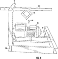
Figure 3 illustrates components shown inFigure 2 with the lifting mechanism in position above a compressor for lifting the compressor from the base. -
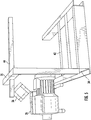
Figure 4 illustrates the compressor ofFigures 2 and3 removed from the base and supported in a manner so that it is moveable relative to the frame into or out of an installation position. -
Figure 5 illustrates the compressor ofFigures 2-4 supported at least partially outside of the footprint of the frame. -
Figure 6 illustrates another feature of the example embodiment ofFigure 1 . -
Figure 1 illustrates arefrigerant system 20. Arefrigerant circuit 22 includes a plurality ofcompressors support frame 30 supports the components of therefrigerant circuit 22 including thecompressors support frame 30 includes horizontally oriented beams orsupport members members - The
compressors 24 are supported on abase 40 and thecompressors 26 are supported on abase 42. Thebase 40 and thebase 42 are part of thesupport frame 30. -
Lifting support members 44, which are part of theframe 30, are situated above thecompressors 26. Additionallifting support members 46 are provided beneath thecompressors 24, respectively. Thelifting support members compressors base members 44, in this example, comprise beams or rails that facilitate movement of thecorresponding compressors 26 into or out of an installed position on thebase 42. Thelifting support members 46, in this example, are part of thebase 40 that facilitate movement of thecorresponding compressors 24 into or out of an installed position on thebase 40. - The
lifting support members frame 30. In some embodiments, thelifting support members lifting support members frame 30 but theframe 30 has corresponding structural features to receive such a removable lifting support member. For example, one or more of the beam orsupport members lifting support member lifting support member frame 30 where it can be secured to theframe 30. - Having lifting
support members frame 30 that facilitates movement of the respective compressors into or out of installed positions on acorresponding base lifting support members frame 30 at the installation site where therefrigerant system 20 is used to provide cooling or refrigeration. The lifting supportmembers frame 30 facilitate such movement of thecompressors -
Figure 2 shows selected portions of theframe 30 and anexample compressor 26 situated on thebase 42. A correspondinglifting support member 44 comprises a generally C-shaped beam or rail in a horizontal position above thecompressor 26. As shown inFigure 2 , two of thestructural support members 35, 35' are situated perpendicular to thelifting support member 44. Thelifting support member 44 is supported by thestructural support members 35 and 35' near opposite ends of thelifting support member 44. The manner in which the different structural components of theframe 30 are secured together may vary depending on the particular embodiment. Those skilled in the art who have the benefit of this description will realize what arrangement of frame components will best suit their particular needs. - The lifting
support member 44 includes achannel 50 having asurface 52 that a plurality ofrollers 54 on alifting mechanism 56 engage for moving thelifting mechanism 56 within thechannel 50. Thesurfaces 52 of the liftingsupport member 44 provide a bearing surface against which therollers 54 are received as thelifting mechanism 56 supports the load of thecompressor 26 and thecompressor 26 is off thebase 42. In this example, the liftingsupport member 44 has a length and is configured to facilitate movement of therespective compressor 26 relative to theframe 30 in a direction parallel to the length of thebeam 44 .Thechannel 50 is aligned with the length and guides movement of thelifting mechanism 56 along the direction of movement represented by thearrow 58. - Assuming the
compressor 26 is in the installed position shown inFigure 2 , therollers 54 of thelifting mechanism 56 may be inserted into thechannel 50 and thelifting mechanism 56 can then be moved into a position above thecompressor 26 as shown inFigure 3 . Thelifting mechanism 56 may then be adjusted into a position where it can be coupled with thecompressor 26 as schematically shown by thearrows 60. Many known compressors have features that facilitate lifting the compressor and such features are useful in the illustrated example embodiment. Once an appropriate connection is made, an individual manipulates or operates thelifting mechanism 56 to lift thecompressor 26 from the base 42 into a position shown inFigure 4 . - Under the circumstance shown in
Figure 4 , the liftingsupport member 44 supports the load of the compressor 26 (and the lifting mechanism 56). The support members of theframe 30 that provide support to the liftingsupport member 44 bear some of the load. - The
rollers 54 of thelifting mechanism 56 follow thesurfaces 52 in thechannel 50 to facilitate moving thecompressor 26 relative to theframe 30 as schematically shown by thearrows 62 inFigure 4 . Assuming thecompressor 26 requires repair or replacement, moving the compressor to the left (according toFigure 4 ) brings thecompressor 26 at least partially outside of the envelope or footprint of theframe 30 as shown inFigure 5 where it can be more easily handled by a mechanic or technician. Thelifting mechanism 56 and the liftingsupport member 44 also facilitate moving the compressor 26 (or its replacement) back into the installed position shown inFigure 2 . - The
base 40 includes liftingsupport members 46 integrally formed as part of thebase 40. As shown inFigure 6 , the illustrated example embodiment includes channel members orportions 46 that establish a pathway for rollers 54' of a lifting mechanism 56' to follow as schematically represented by thearrows 64. Thechannel 46 facilitates directing the lifting mechanism 56' into position beneath one of thecompressors 24 for lifting that compressor off thebase 40 and maneuvering it into a position at least partially outside the envelope or footprint of theframe 30 where thecompressor 24 can be more conveniently serviced or removed from the site of therefrigerant system 20. - The lifting
mechanisms 56 and 56' are illustrated as scissor lift mechanisms. Those skilled in the art who have the benefit of this description will understand that other types of lifting mechanisms or jacks can be used for lifting and supporting a compressor off of a base from above or beneath the compressor. - Including lifting support members as part of the
frame 30 that supports thecompressors refrigerant circuit 22 is utilized on an ongoing basis provides improved ergonomics and convenience for procedures that require maneuvering a compressor relative to thesupport frame 30. No external machines, such as forklifts, are necessary and maintenance or replacement of compressors can be accomplished more quickly and economically. - The preceding description is exemplary rather than limiting in nature. Variations and modifications to the disclosed examples may become apparent to those skilled in the art that do not necessarily depart from the essence of this invention. The scope of legal protection given to this invention can only be determined by studying the following claims.
Claims (15)
- A refrigerant system, comprising:at least one refrigerant circuit including at least one compressor; anda frame that supports the compressor, the frame includinga plurality of structural support members,at least one base supported by the structural support members, the compressor being supported on the at least one base, andat least one lifting support member situated above or below the compressor, the at least one lifting support member being configured to support a load of the compressor and configured to facilitate movement of the compressor relative to the base when the compressor is off the base, at least some of the plurality of structural support members bearing at least a portion of the load of the compressor when the load of the compressor is supported by the at least one lifting support member.
- The refrigerant system of claim 1, wherein
the at least one lifting support member comprises a beam or a rail;
the beam or rail has a length; and
the beam or rail is configured to facilitate movement of the compressor relative to the frame in a direction that is parallel to the length. - The refrigerant system of claim 1 or 2, wherein
at least two of the structural support members are situated perpendicular to the at least one lifting support member; and
the at least one lifting support member is supported by the at least two of the structural support members near opposite ends of the at least one lifting support member. - The refrigerant system of any of the preceding claims, comprising a lifting mechanism configured to lift the compressor off the base.
- The refrigerant system of claim 4, wherein the at least one lifting support member includes a surface that the lifting mechanism engages while lifting the compressor off the base and while supporting the load of the compressor.
- The refrigerant system of claim 5, wherein
the at least one lifting support member includes a channel; and
the surface is within the channel. - The refrigerant system of claim 5 or 6, wherein
the surface is oriented along a direction of intended movement of the compressor relative to the frame; and
the lifting mechanism is moveable along the surface in the direction of intended movement. - The refrigerant system of any of the preceding claims, wherein
the at least one lifting support member comprises a plurality of lifting support members; and
a second one of the lifting support members is situated above or below a second compressor of the compressors. - The refrigerant system of claim 8, wherein each of the compressors is situated below or above at least one of the lifting support members.
- The refrigerant system of claim 8 or 9, comprising a lifting mechanism configured to lift the compressors, respectively, off the base and wherein the lifting mechanism is selectively engaged with different ones of the lifting support members for lifting different ones of the compressors off the base.
- The refrigerant system of any of the preceding claims, wherein the at least one lifting support member comprises a portion of the base.
- The refrigerant system of claim 11, wherein the at least one lifting support member comprises a channel configured to guide movement of a lifting mechanism into a position beneath the compressor.
- The refrigerant system of any of the preceding claims, wherein
the at least one compressor comprises a plurality of compressors; and
the at least one lifting support member comprises a plurality of lifting support members respectively above or below associated ones of the compressors. - The refrigerant system of any of the preceding claims, wherein the at least one lifting support member is situated in a single, fixed position relative to the frame.
- The refrigerant system of any of the preceding claims, wherein
the at least one lifting support member is selectively removable from the position above or below the compressor; and
at least one of the structural support members includes a feature that cooperates with a corresponding feature on the at least one lifting support member to locate the lifting support member on the frame.
Priority Applications (4)
| Application Number | Priority Date | Filing Date | Title |
|---|---|---|---|
| DK18200209.7T DK3636922T3 (en) | 2018-10-12 | 2018-10-12 | REFRIGERATOR SYSTEM FRAME INCLUDING COMPRESSOR LIFT SUPPORT ELEMENTS |
| EP18200209.7A EP3636922B1 (en) | 2018-10-12 | 2018-10-12 | Refrigerant system frame including compressor lifting support members |
| PCT/US2019/048308 WO2020076430A1 (en) | 2018-10-12 | 2019-08-27 | Refrigerant system frame including compressor lifting support members |
| CN201980042794.9A CN112384698A (en) | 2018-10-12 | 2019-08-27 | Refrigerant system frame including compressor lift support member |
Applications Claiming Priority (1)
| Application Number | Priority Date | Filing Date | Title |
|---|---|---|---|
| EP18200209.7A EP3636922B1 (en) | 2018-10-12 | 2018-10-12 | Refrigerant system frame including compressor lifting support members |
Publications (2)
| Publication Number | Publication Date |
|---|---|
| EP3636922A1 true EP3636922A1 (en) | 2020-04-15 |
| EP3636922B1 EP3636922B1 (en) | 2022-03-02 |
Family
ID=63840755
Family Applications (1)
| Application Number | Title | Priority Date | Filing Date |
|---|---|---|---|
| EP18200209.7A Active EP3636922B1 (en) | 2018-10-12 | 2018-10-12 | Refrigerant system frame including compressor lifting support members |
Country Status (4)
| Country | Link |
|---|---|
| EP (1) | EP3636922B1 (en) |
| CN (1) | CN112384698A (en) |
| DK (1) | DK3636922T3 (en) |
| WO (1) | WO2020076430A1 (en) |
Citations (5)
| Publication number | Priority date | Publication date | Assignee | Title |
|---|---|---|---|---|
| US3323625A (en) * | 1965-07-28 | 1967-06-06 | Thermo King Corp | Detachable power assembly |
| FR2807412A1 (en) * | 2000-04-07 | 2001-10-12 | Profroid | Procedure for facilitating movement of heavy object on base by lifting and inserting transfer panel and supporting plate |
| WO2008030930A2 (en) * | 2006-09-07 | 2008-03-13 | Carrier Corporation | Compressor service tool |
| US7862285B1 (en) * | 2006-02-21 | 2011-01-04 | Michael J Dove | Compressor trolley |
| US20150338141A1 (en) * | 2014-05-23 | 2015-11-26 | Lennox Industries Inc. | Tandem Compressor Slide Rail |
-
2018
- 2018-10-12 EP EP18200209.7A patent/EP3636922B1/en active Active
- 2018-10-12 DK DK18200209.7T patent/DK3636922T3/en active
-
2019
- 2019-08-27 WO PCT/US2019/048308 patent/WO2020076430A1/en not_active Ceased
- 2019-08-27 CN CN201980042794.9A patent/CN112384698A/en active Pending
Patent Citations (5)
| Publication number | Priority date | Publication date | Assignee | Title |
|---|---|---|---|---|
| US3323625A (en) * | 1965-07-28 | 1967-06-06 | Thermo King Corp | Detachable power assembly |
| FR2807412A1 (en) * | 2000-04-07 | 2001-10-12 | Profroid | Procedure for facilitating movement of heavy object on base by lifting and inserting transfer panel and supporting plate |
| US7862285B1 (en) * | 2006-02-21 | 2011-01-04 | Michael J Dove | Compressor trolley |
| WO2008030930A2 (en) * | 2006-09-07 | 2008-03-13 | Carrier Corporation | Compressor service tool |
| US20150338141A1 (en) * | 2014-05-23 | 2015-11-26 | Lennox Industries Inc. | Tandem Compressor Slide Rail |
Also Published As
| Publication number | Publication date |
|---|---|
| DK3636922T3 (en) | 2022-06-13 |
| CN112384698A (en) | 2021-02-19 |
| WO2020076430A1 (en) | 2020-04-16 |
| EP3636922B1 (en) | 2022-03-02 |
Similar Documents
| Publication | Publication Date | Title |
|---|---|---|
| US10168082B2 (en) | Tandem compressor slide rail | |
| US20240401827A1 (en) | Air-conditioning apparatus | |
| US20160159628A1 (en) | Scissor lift table and method for changing a fixed bearing of a scissor lift table | |
| EP3636922B1 (en) | Refrigerant system frame including compressor lifting support members | |
| US11235926B2 (en) | Storage system including a vertical transfer device | |
| KR20150004209A (en) | Trolley for transporting heat exchange coil of cooling condencing unit in offshore plant | |
| CN107270519A (en) | Chassis structure and air conditioning unit | |
| CN208992567U (en) | Air-conditioning condenser mainboard positioning mechanism | |
| EP3922593A1 (en) | Lifter | |
| KR102667327B1 (en) | Elevating ceiling buffer | |
| WO2015114396A1 (en) | Vertical sliding solution of the condenser unit for trucks with refrigerated goods | |
| CN221553063U (en) | Embedded single-drive platform structure | |
| US11112129B2 (en) | HVAC unit centering systems and methods | |
| CN107508169A (en) | A kind of electrical engineering portable type regulator cubicle | |
| CN216371210U (en) | Fixing device is used in processing of air conditioner copper pipe | |
| CN218863093U (en) | High-low temperature resistant multifunctional linear telescopic slide rail | |
| CN207188549U (en) | A kind of air conditioning liquid reservoir steel pipe augomatic syphon device | |
| US20260092710A1 (en) | Outdoor unit for heat pump | |
| CN110064919B (en) | Multi-station mechanism for automatically providing bolts | |
| KR100762139B1 (en) | Oil pressure control device and air conditioner having the same | |
| CN203908321U (en) | Quick feeding and discharging equipment for multilayer box type heating furnace | |
| CN204356024U (en) | Paper box clip | |
| JP7706279B2 (en) | Air conditioner stand and air conditioner equipped with same | |
| JP5595766B2 (en) | Refrigeration equipment | |
| KR200195224Y1 (en) | System for manual guided vehicle |
Legal Events
| Date | Code | Title | Description |
|---|---|---|---|
| PUAI | Public reference made under article 153(3) epc to a published international application that has entered the european phase |
Free format text: ORIGINAL CODE: 0009012 |
|
| STAA | Information on the status of an ep patent application or granted ep patent |
Free format text: STATUS: THE APPLICATION HAS BEEN PUBLISHED |
|
| AK | Designated contracting states |
Kind code of ref document: A1 Designated state(s): AL AT BE BG CH CY CZ DE DK EE ES FI FR GB GR HR HU IE IS IT LI LT LU LV MC MK MT NL NO PL PT RO RS SE SI SK SM TR |
|
| AX | Request for extension of the european patent |
Extension state: BA ME |
|
| STAA | Information on the status of an ep patent application or granted ep patent |
Free format text: STATUS: REQUEST FOR EXAMINATION WAS MADE |
|
| STAA | Information on the status of an ep patent application or granted ep patent |
Free format text: STATUS: EXAMINATION IS IN PROGRESS |
|
| 17P | Request for examination filed |
Effective date: 20201009 |
|
| RBV | Designated contracting states (corrected) |
Designated state(s): AL AT BE BG CH CY CZ DE DK EE ES FI FR GB GR HR HU IE IS IT LI LT LU LV MC MK MT NL NO PL PT RO RS SE SI SK SM TR |
|
| 17Q | First examination report despatched |
Effective date: 20201027 |
|
| GRAP | Despatch of communication of intention to grant a patent |
Free format text: ORIGINAL CODE: EPIDOSNIGR1 |
|
| STAA | Information on the status of an ep patent application or granted ep patent |
Free format text: STATUS: GRANT OF PATENT IS INTENDED |
|
| INTG | Intention to grant announced |
Effective date: 20210916 |
|
| GRAS | Grant fee paid |
Free format text: ORIGINAL CODE: EPIDOSNIGR3 |
|
| GRAA | (expected) grant |
Free format text: ORIGINAL CODE: 0009210 |
|
| STAA | Information on the status of an ep patent application or granted ep patent |
Free format text: STATUS: THE PATENT HAS BEEN GRANTED |
|
| AK | Designated contracting states |
Kind code of ref document: B1 Designated state(s): AL AT BE BG CH CY CZ DE DK EE ES FI FR GB GR HR HU IE IS IT LI LT LU LV MC MK MT NL NO PL PT RO RS SE SI SK SM TR |
|
| REG | Reference to a national code |
Ref country code: GB Ref legal event code: FG4D |
|
| REG | Reference to a national code |
Ref country code: CH Ref legal event code: EP Ref country code: AT Ref legal event code: REF Ref document number: 1472447 Country of ref document: AT Kind code of ref document: T Effective date: 20220315 |
|
| REG | Reference to a national code |
Ref country code: DE Ref legal event code: R096 Ref document number: 602018031517 Country of ref document: DE |
|
| REG | Reference to a national code |
Ref country code: IE Ref legal event code: FG4D |
|
| REG | Reference to a national code |
Ref country code: DK Ref legal event code: T3 Effective date: 20220608 |
|
| REG | Reference to a national code |
Ref country code: NL Ref legal event code: FP |
|
| REG | Reference to a national code |
Ref country code: SE Ref legal event code: TRGR |
|
| REG | Reference to a national code |
Ref country code: LT Ref legal event code: MG9D |
|
| PG25 | Lapsed in a contracting state [announced via postgrant information from national office to epo] |
Ref country code: RS Free format text: LAPSE BECAUSE OF FAILURE TO SUBMIT A TRANSLATION OF THE DESCRIPTION OR TO PAY THE FEE WITHIN THE PRESCRIBED TIME-LIMIT Effective date: 20220302 Ref country code: LT Free format text: LAPSE BECAUSE OF FAILURE TO SUBMIT A TRANSLATION OF THE DESCRIPTION OR TO PAY THE FEE WITHIN THE PRESCRIBED TIME-LIMIT Effective date: 20220302 Ref country code: HR Free format text: LAPSE BECAUSE OF FAILURE TO SUBMIT A TRANSLATION OF THE DESCRIPTION OR TO PAY THE FEE WITHIN THE PRESCRIBED TIME-LIMIT Effective date: 20220302 Ref country code: ES Free format text: LAPSE BECAUSE OF FAILURE TO SUBMIT A TRANSLATION OF THE DESCRIPTION OR TO PAY THE FEE WITHIN THE PRESCRIBED TIME-LIMIT Effective date: 20220302 Ref country code: BG Free format text: LAPSE BECAUSE OF FAILURE TO SUBMIT A TRANSLATION OF THE DESCRIPTION OR TO PAY THE FEE WITHIN THE PRESCRIBED TIME-LIMIT Effective date: 20220602 |
|
| REG | Reference to a national code |
Ref country code: NO Ref legal event code: T2 Effective date: 20220302 |
|
| REG | Reference to a national code |
Ref country code: AT Ref legal event code: MK05 Ref document number: 1472447 Country of ref document: AT Kind code of ref document: T Effective date: 20220302 |
|
| PG25 | Lapsed in a contracting state [announced via postgrant information from national office to epo] |
Ref country code: PL Free format text: LAPSE BECAUSE OF FAILURE TO SUBMIT A TRANSLATION OF THE DESCRIPTION OR TO PAY THE FEE WITHIN THE PRESCRIBED TIME-LIMIT Effective date: 20220302 Ref country code: LV Free format text: LAPSE BECAUSE OF FAILURE TO SUBMIT A TRANSLATION OF THE DESCRIPTION OR TO PAY THE FEE WITHIN THE PRESCRIBED TIME-LIMIT Effective date: 20220302 Ref country code: GR Free format text: LAPSE BECAUSE OF FAILURE TO SUBMIT A TRANSLATION OF THE DESCRIPTION OR TO PAY THE FEE WITHIN THE PRESCRIBED TIME-LIMIT Effective date: 20220603 Ref country code: FI Free format text: LAPSE BECAUSE OF FAILURE TO SUBMIT A TRANSLATION OF THE DESCRIPTION OR TO PAY THE FEE WITHIN THE PRESCRIBED TIME-LIMIT Effective date: 20220302 |
|
| PG25 | Lapsed in a contracting state [announced via postgrant information from national office to epo] |
Ref country code: SM Free format text: LAPSE BECAUSE OF FAILURE TO SUBMIT A TRANSLATION OF THE DESCRIPTION OR TO PAY THE FEE WITHIN THE PRESCRIBED TIME-LIMIT Effective date: 20220302 Ref country code: SK Free format text: LAPSE BECAUSE OF FAILURE TO SUBMIT A TRANSLATION OF THE DESCRIPTION OR TO PAY THE FEE WITHIN THE PRESCRIBED TIME-LIMIT Effective date: 20220302 Ref country code: RO Free format text: LAPSE BECAUSE OF FAILURE TO SUBMIT A TRANSLATION OF THE DESCRIPTION OR TO PAY THE FEE WITHIN THE PRESCRIBED TIME-LIMIT Effective date: 20220302 Ref country code: PT Free format text: LAPSE BECAUSE OF FAILURE TO SUBMIT A TRANSLATION OF THE DESCRIPTION OR TO PAY THE FEE WITHIN THE PRESCRIBED TIME-LIMIT Effective date: 20220704 Ref country code: EE Free format text: LAPSE BECAUSE OF FAILURE TO SUBMIT A TRANSLATION OF THE DESCRIPTION OR TO PAY THE FEE WITHIN THE PRESCRIBED TIME-LIMIT Effective date: 20220302 Ref country code: CZ Free format text: LAPSE BECAUSE OF FAILURE TO SUBMIT A TRANSLATION OF THE DESCRIPTION OR TO PAY THE FEE WITHIN THE PRESCRIBED TIME-LIMIT Effective date: 20220302 Ref country code: AT Free format text: LAPSE BECAUSE OF FAILURE TO SUBMIT A TRANSLATION OF THE DESCRIPTION OR TO PAY THE FEE WITHIN THE PRESCRIBED TIME-LIMIT Effective date: 20220302 |
|
| PG25 | Lapsed in a contracting state [announced via postgrant information from national office to epo] |
Ref country code: IS Free format text: LAPSE BECAUSE OF FAILURE TO SUBMIT A TRANSLATION OF THE DESCRIPTION OR TO PAY THE FEE WITHIN THE PRESCRIBED TIME-LIMIT Effective date: 20220702 Ref country code: AL Free format text: LAPSE BECAUSE OF FAILURE TO SUBMIT A TRANSLATION OF THE DESCRIPTION OR TO PAY THE FEE WITHIN THE PRESCRIBED TIME-LIMIT Effective date: 20220302 |
|
| REG | Reference to a national code |
Ref country code: DE Ref legal event code: R097 Ref document number: 602018031517 Country of ref document: DE |
|
| PLBE | No opposition filed within time limit |
Free format text: ORIGINAL CODE: 0009261 |
|
| STAA | Information on the status of an ep patent application or granted ep patent |
Free format text: STATUS: NO OPPOSITION FILED WITHIN TIME LIMIT |
|
| 26N | No opposition filed |
Effective date: 20221205 |
|
| PG25 | Lapsed in a contracting state [announced via postgrant information from national office to epo] |
Ref country code: SI Free format text: LAPSE BECAUSE OF FAILURE TO SUBMIT A TRANSLATION OF THE DESCRIPTION OR TO PAY THE FEE WITHIN THE PRESCRIBED TIME-LIMIT Effective date: 20220302 |
|
| PG25 | Lapsed in a contracting state [announced via postgrant information from national office to epo] |
Ref country code: MC Free format text: LAPSE BECAUSE OF FAILURE TO SUBMIT A TRANSLATION OF THE DESCRIPTION OR TO PAY THE FEE WITHIN THE PRESCRIBED TIME-LIMIT Effective date: 20220302 |
|
| REG | Reference to a national code |
Ref country code: BE Ref legal event code: MM Effective date: 20221031 |
|
| PG25 | Lapsed in a contracting state [announced via postgrant information from national office to epo] |
Ref country code: LU Free format text: LAPSE BECAUSE OF NON-PAYMENT OF DUE FEES Effective date: 20221012 |
|
| PG25 | Lapsed in a contracting state [announced via postgrant information from national office to epo] |
Ref country code: BE Free format text: LAPSE BECAUSE OF NON-PAYMENT OF DUE FEES Effective date: 20221031 |
|
| PG25 | Lapsed in a contracting state [announced via postgrant information from national office to epo] |
Ref country code: IE Free format text: LAPSE BECAUSE OF NON-PAYMENT OF DUE FEES Effective date: 20221012 |
|
| PG25 | Lapsed in a contracting state [announced via postgrant information from national office to epo] |
Ref country code: HU Free format text: LAPSE BECAUSE OF FAILURE TO SUBMIT A TRANSLATION OF THE DESCRIPTION OR TO PAY THE FEE WITHIN THE PRESCRIBED TIME-LIMIT; INVALID AB INITIO Effective date: 20181012 |
|
| PG25 | Lapsed in a contracting state [announced via postgrant information from national office to epo] |
Ref country code: CY Free format text: LAPSE BECAUSE OF FAILURE TO SUBMIT A TRANSLATION OF THE DESCRIPTION OR TO PAY THE FEE WITHIN THE PRESCRIBED TIME-LIMIT Effective date: 20220302 |
|
| PG25 | Lapsed in a contracting state [announced via postgrant information from national office to epo] |
Ref country code: MK Free format text: LAPSE BECAUSE OF FAILURE TO SUBMIT A TRANSLATION OF THE DESCRIPTION OR TO PAY THE FEE WITHIN THE PRESCRIBED TIME-LIMIT Effective date: 20220302 |
|
| PG25 | Lapsed in a contracting state [announced via postgrant information from national office to epo] |
Ref country code: MT Free format text: LAPSE BECAUSE OF FAILURE TO SUBMIT A TRANSLATION OF THE DESCRIPTION OR TO PAY THE FEE WITHIN THE PRESCRIBED TIME-LIMIT Effective date: 20220302 |
|
| PGFP | Annual fee paid to national office [announced via postgrant information from national office to epo] |
Ref country code: DK Payment date: 20250923 Year of fee payment: 8 |
|
| PGFP | Annual fee paid to national office [announced via postgrant information from national office to epo] |
Ref country code: NO Payment date: 20250925 Year of fee payment: 8 |
|
| PGFP | Annual fee paid to national office [announced via postgrant information from national office to epo] |
Ref country code: NL Payment date: 20250923 Year of fee payment: 8 Ref country code: IT Payment date: 20250923 Year of fee payment: 8 |
|
| PGFP | Annual fee paid to national office [announced via postgrant information from national office to epo] |
Ref country code: GB Payment date: 20250923 Year of fee payment: 8 |
|
| PGFP | Annual fee paid to national office [announced via postgrant information from national office to epo] |
Ref country code: FR Payment date: 20250924 Year of fee payment: 8 |
|
| PGFP | Annual fee paid to national office [announced via postgrant information from national office to epo] |
Ref country code: SE Payment date: 20250923 Year of fee payment: 8 |
|
| REG | Reference to a national code |
Ref country code: CH Ref legal event code: U11 Free format text: ST27 STATUS EVENT CODE: U-0-0-U10-U11 (AS PROVIDED BY THE NATIONAL OFFICE) Effective date: 20251101 |
|
| PG25 | Lapsed in a contracting state [announced via postgrant information from national office to epo] |
Ref country code: TR Free format text: LAPSE BECAUSE OF FAILURE TO SUBMIT A TRANSLATION OF THE DESCRIPTION OR TO PAY THE FEE WITHIN THE PRESCRIBED TIME-LIMIT Effective date: 20220302 |
|
| PGFP | Annual fee paid to national office [announced via postgrant information from national office to epo] |
Ref country code: DE Payment date: 20250923 Year of fee payment: 8 |
|
| PGFP | Annual fee paid to national office [announced via postgrant information from national office to epo] |
Ref country code: CH Payment date: 20251101 Year of fee payment: 8 |