EP3636906A1 - Afterburner system - Google Patents
Afterburner system Download PDFInfo
- Publication number
- EP3636906A1 EP3636906A1 EP19197014.4A EP19197014A EP3636906A1 EP 3636906 A1 EP3636906 A1 EP 3636906A1 EP 19197014 A EP19197014 A EP 19197014A EP 3636906 A1 EP3636906 A1 EP 3636906A1
- Authority
- EP
- European Patent Office
- Prior art keywords
- core
- flow
- duct
- flow duct
- engine
- Prior art date
- Legal status (The legal status is an assumption and is not a legal conclusion. Google has not performed a legal analysis and makes no representation as to the accuracy of the status listed.)
- Granted
Links
Images

Classifications
-
- F—MECHANICAL ENGINEERING; LIGHTING; HEATING; WEAPONS; BLASTING
- F02—COMBUSTION ENGINES; HOT-GAS OR COMBUSTION-PRODUCT ENGINE PLANTS
- F02K—JET-PROPULSION PLANTS
- F02K3/00—Plants including a gas turbine driving a compressor or a ducted fan
- F02K3/08—Plants including a gas turbine driving a compressor or a ducted fan with supplementary heating of the working fluid; Control thereof
- F02K3/10—Plants including a gas turbine driving a compressor or a ducted fan with supplementary heating of the working fluid; Control thereof by after-burners
-
- F—MECHANICAL ENGINEERING; LIGHTING; HEATING; WEAPONS; BLASTING
- F02—COMBUSTION ENGINES; HOT-GAS OR COMBUSTION-PRODUCT ENGINE PLANTS
- F02K—JET-PROPULSION PLANTS
- F02K1/00—Plants characterised by the form or arrangement of the jet pipe or nozzle; Jet pipes or nozzles peculiar thereto
- F02K1/04—Mounting of an exhaust cone in the jet pipe
-
- F—MECHANICAL ENGINEERING; LIGHTING; HEATING; WEAPONS; BLASTING
- F02—COMBUSTION ENGINES; HOT-GAS OR COMBUSTION-PRODUCT ENGINE PLANTS
- F02K—JET-PROPULSION PLANTS
- F02K3/00—Plants including a gas turbine driving a compressor or a ducted fan
- F02K3/02—Plants including a gas turbine driving a compressor or a ducted fan in which part of the working fluid by-passes the turbine and combustion chamber
- F02K3/04—Plants including a gas turbine driving a compressor or a ducted fan in which part of the working fluid by-passes the turbine and combustion chamber the plant including ducted fans, i.e. fans with high volume, low pressure outputs, for augmenting the jet thrust, e.g. of double-flow type
- F02K3/06—Plants including a gas turbine driving a compressor or a ducted fan in which part of the working fluid by-passes the turbine and combustion chamber the plant including ducted fans, i.e. fans with high volume, low pressure outputs, for augmenting the jet thrust, e.g. of double-flow type with front fan
-
- F—MECHANICAL ENGINEERING; LIGHTING; HEATING; WEAPONS; BLASTING
- F23—COMBUSTION APPARATUS; COMBUSTION PROCESSES
- F23R—GENERATING COMBUSTION PRODUCTS OF HIGH PRESSURE OR HIGH VELOCITY, e.g. GAS-TURBINE COMBUSTION CHAMBERS
- F23R3/00—Continuous combustion chambers using liquid or gaseous fuel
- F23R3/02—Continuous combustion chambers using liquid or gaseous fuel characterised by the air-flow or gas-flow configuration
- F23R3/26—Controlling the air flow
-
- F—MECHANICAL ENGINEERING; LIGHTING; HEATING; WEAPONS; BLASTING
- F23—COMBUSTION APPARATUS; COMBUSTION PROCESSES
- F23R—GENERATING COMBUSTION PRODUCTS OF HIGH PRESSURE OR HIGH VELOCITY, e.g. GAS-TURBINE COMBUSTION CHAMBERS
- F23R3/00—Continuous combustion chambers using liquid or gaseous fuel
- F23R3/28—Continuous combustion chambers using liquid or gaseous fuel characterised by the fuel supply
- F23R3/34—Feeding into different combustion zones
-
- F—MECHANICAL ENGINEERING; LIGHTING; HEATING; WEAPONS; BLASTING
- F02—COMBUSTION ENGINES; HOT-GAS OR COMBUSTION-PRODUCT ENGINE PLANTS
- F02C—GAS-TURBINE PLANTS; AIR INTAKES FOR JET-PROPULSION PLANTS; CONTROLLING FUEL SUPPLY IN AIR-BREATHING JET-PROPULSION PLANTS
- F02C3/00—Gas-turbine plants characterised by the use of combustion products as the working fluid
- F02C3/04—Gas-turbine plants characterised by the use of combustion products as the working fluid having a turbine driving a compressor
Definitions
- the present disclosure relates to a turbofan engine, such as a turbofan engine for use on a supersonic aircraft, and an afterburner system for such an engine.
- a turbofan engine typically comprises, in axial flow series, an air intake, a propulsive fan, one or more compressors, combustion equipment, and one or more turbines. Air entering the intake is accelerated by the fan to produce two air flows: a core flow into the one or more compressors and a bypass flow which passes through a bypass duct and to provide propulsive thrust. The compressed air exhausted from the compressor(s) is directed into the combustion equipment where it is mixed with fuel and the mixture combusted. The resultant hot combustion products then expand through, and thereby drive the turbine(s), before being exhausted as a core exhaust flow to provide further propulsive thrust.
- Afterburning, or re-heating, systems introduce additional fuel into the exhaust flow and ignite it for limited periods. This increase in the temperature of the exhaust flow increases the thrust provided by the engine, and can be particularly beneficially employed during the operation of supersonic engines.
- conventional afterburner systems introduce significant performance penalties, particularly during non-afterburning operations, as they impact the entire exhaust flow. There is a desire then to provide an afterburner system which, during non-afterburning operations, reduces these performance penalties.
- the present disclosure provides a turbofan engine, an afterburner system, a supersonic aircraft, and method of providing a temporary thrust boost in the supersonic aircraft, as set out in the appended claims.
- turbofan engine having:
- the use of the afterburner system of the first aspect introduces an area change in the hot chute of the turbofan engine (i.e. via the closure of the doors), which can give an additional thrust boost during the engine's cycle.
- reheating is limited to the core flow and therefore the need for high temperature materials in other components (for example the first exhaust nozzle) can be avoided, i.e. because the bypass airflow is not reheated.
- the turbofan engine may have any one or, to the extent that they are compatible, any combination of the following optional features.
- the turbofan engine may be configured for supersonic flight operation.
- the first exhaust nozzle may also define a downstream end of the bypass duct.
- the engine may further have an exhaust duct receiving the bypass air flow and the core exhaust flow and exhausting these flows at a second exhaust nozzle.
- the first exhaust nozzle may then be a mixer nozzle which encourages mixing of the bypass air flow and the core exhaust flow downstream thereof.
- the mixer nozzle may be a lobed mixer nozzle.
- the bypass air flow is typically much cooler than the reheated core exhaust flow. As such, the bypass air flow may protect other components, for example the first exhaust nozzle and the second exhaust nozzle, from thermal damage from the reheated flow.
- the or each door may be a covering or flap over the respective entrance of the second core flow duct located upstream of the one or more fuel injectors and igniters.
- the or each fuel injector and its respective igniter may be a single unit or, alternatively, may be separate units.
- the or each door may be actively maintained in an open configuration during normal operation, i.e. via one or more mechanisms or, may be configured so as to be held open by exhaust gas pressure.
- the afterburner system may further comprise a fuel-based hydraulic system for actuating the opening and closing of the doors.
- the fuel injectors and igniters may be configured to be concealed from the second core flow duct when the doors are open and revealed to the second core flow duct when the doors are closed. As such, any deleterious flow-disturbing effects of the fuel injectors and igniters during normal (non-reheating) operation can be reduced.
- the second core flow duct may be an annular duct coaxial with the axis of the engine.
- the afterburner system may comprise plural doors circumferentially spaced around the core plug.
- the afterburner system may include flow straighteners located between respective pairs of adjacent doors.
- the doors when closed, may merely reduce the amount of flow diversion from the second core flow duct to form a purge flow in the second core flow duct.
- the doors may be configured to completely seal the entrances of the second core flow duct when closed to prevent the flow diversion.
- the afterburner system may be configured to form, downstream of the second core flow duct when the doors are closed, a recirculating airflow.
- the recirculating airflow may provide a region with a relatively low air speed (in a direction axially away from the core plug) whereupon a more stable flame can be formed during reheat operation.
- the afterburner system may further comprise a physical flameholder to stabilise the flame.
- the flameholder may be configured to be concealed from the second core flow duct when the doors are open and revealed to the second core flow duct when the doors are closed.
- an afterburner system installable downstream of an engine core of a turbofan engine, the system including:
- the afterburner system of the second aspect may be the afterburner system as referred to in the first aspect, and may have any one or, to the extent that they are compatible, any combination of the optional features related thereto.
- a supersonic aircraft having one or more turbofan engines according to the first aspect.
- a method of providing a temporary thrust boost in the supersonic aircraft of the third aspect including the step of: closing the doors so as to at least partially block the entrances to the second core flow duct.
- merely closing the doors can provide a temporary thrust boost by shifting the engine operation point.
- the method may have any one or, to the extent that they are compatible, any combination of the following optional features.
- the method may further include the step of injecting and igniting fuel within the second core flow duct, thereby providing a reheated airflow and a temporary thrust boost.
- the closing, and injecting and igniting steps may be performed in either order.
- the step of closing the doors is performed before the step of injecting and igniting the fuel.
- the temporary thrust boost provided by the reheated airflow is significantly greater than that provided by merely closing the doors.
- the method may further include the step, performed after the closing step, of: re-opening the doors.
- the method may further include the step, performed after the injecting and igniting of: ending the injection and ignition of fuel within the second core flow duct.
- the ending the injection and ignition, and re-opening steps may be performed in either order.
- the step of ending the injection and ignition is performed before the step of re-opening the doors.
- the temporary thrust boost may be performed as part of a trans-sonic thrust operation. Alternatively, or additionally, the temporary thrust boost may be performed during either or both of a take-off operation and a climbing operation.
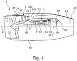
- FIG. 1 shows a longitudinal cross-section through a turbofan engine 1 for a civil supersonic aircraft.
- the turbofan engine 1 comprises an engine intake 2, a multi-stage fan 3, a primary flow channel 6 that leads through an engine core, a secondary flow channel 22 that leads past the engine core, a lobed mixer nozzle 23, an exhaust duct 24, and an exhaust nozzle 20 into which a thrust reverser (not shown) can be integrated.
- the turbofan engine 1 has a machine axis or engine centre line 8.
- the machine axis 8 defines an axial direction of the turbofan engine.
- a radial direction of the turbofan engine extends perpendicularly to the axial direction.
- the engine core comprises in a per se known manner a compressor 7, a combustion chamber 11 and a turbine 91, 92.
- the compressor comprises a high-pressure compressor 7.
- a low-pressure compressor is formed by the areas of the multi-stage fan rotor 3 that are located close to the hub.
- the turbine that is arranged behind the combustion chamber 11 comprises a high-pressure turbine 91 and a low-pressure turbine 92.
- the high-pressure turbine 91 drives a high-pressure shaft 81 that connects the high-pressure turbine 91 to the high-pressure compressor 7.
- the low-pressure turbine 92 drives a low-pressure shaft 82 that connects the low-pressure turbine 92 to the multi-stage fan 3.
- the turbofan engine 1 is arranged inside an engine nacelle 10. It is connected to the aircraft fuselage, for example via a pylon.
- the engine intake 2 forms a supersonic air inlet and is correspondingly provided and suitable for slowing down the inflowing air to velocities of below Ma 1.0.
- the engine intake is bevelled, forming an angle ⁇ , wherein the upper edge projects with respect to the lower edge. This serves for a better distribution of compression shocks as they occur in supersonic flight.
- the engine intake can be formed in a straight manner, i.e. with an angle ⁇ of 90°, or a different angle than the one shown.
- the engine intake 2 can have an interior cladding of a sound-absorbing material 21. This serves for reducing engine noise.
- the fan 3 can be formed as a multi-stage fan, in the shown exemplary embodiment as a double-stage fan. Accordingly, the multi-stage fan 3 comprises a fan rotor 31 and a fan stator 32 that form a first, frontal fan stage, as well as a fan rotor 33 and a fan stator 34a, 34b that form a second, rear fan stage. Upstream, the fan 3 is provided with a nose cone 35.
- the fan rotors 31, 33 respectively comprise a plurality of rotor blades.
- the fan stator 32 of the frontal fan stage comprises a plurality of stator blades that are mounted in a fan housing 37.
- the fan stator of the rear fan stage is split and is formed by a guide baffle 34a that is formed at the entry of the primary flow channel 6, and formed by a guide baffle 34b that is formed at the entry of the secondary flow channel 5.
- the fan rotors 31, 33 can be configured in BLISK design and can be fixedly attached to each other.
- the flow channel through the fan 3 is divided into the primary flow channel 6 and the secondary flow channel 22.
- the secondary flow channel 22 is also referred to as the bypass flow channel or the bypass duct.
- the core exhaust flow 201 from the primary flow channel 6 and the bypass air flow from the bypass duct 22 are mixed by the mixer nozzle 23.
- a core plug 30 is inserted behind the low-pressure turbine 92 to realize the desired cross sections of the core exhaust flow.
- the exhaust nozzle 20 can be a variable area exhaust nozzle.
- the core plug 30 includes an afterburner system 40 which is described in more detail below.
- the afterburner can be used as part of a trans-sonic thrust operation of the engine. Alternatively, or additionally, it can be used during a take-off operation and/or a climbing operation.
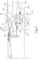
- Figure 2 shows a sectional side of the afterburner system 40 in a non-reheating (normal engine operation) configuration.
- the core exhaust flow 201 from the low-pressure turbine 92 enters an annular first core flow duct 44 which is bounded on its radially outer side by the mixer nozzle 23 and on its radially inner side by the outer surface of the core plug 30.
- An undiverted portion 27a of the core exhaust flow 201 travels through the first flow duct. As it does so, radially outer parts of the undiverted portion 27a mix with radially inner parts of the bypass air flow 202 to form a mixed flow 203.
- radially inner parts of the undiverted portion 27a continue through the first core flow duct 44 to arrive at the downstream end of the outer surface of the core plug 30.
- another portion 27b of the core exhaust flow 201 is diverted from the first flow duct 44 through a circumferential row of entrances 45 formed in the outer surface of the core plug 30 into an annular second core exhaust duct 41, located within the core plug 30.
- These entrances 45 have respective doors 42 which are shown open in Figure 2 .
- Within the second core exhaust duct 41 are one or more fuel injector and igniter units 43, which in normal (non-reheating) engine operation are not used to inject and ignite fuel. Typically plural such units are circumferentially arranged around the duct.
- the number and/or position of the doors 42 can be selected in order to reduce noise generation by the afterburner system.
- the diverted portion 27b of the core exhaust flow re-joins the radially inner parts of the undiverted portion 27a downstream of the fuel injector and igniter units 43 as a reformed core exhaust flow 204. This then exits the mixer nozzle 23 for onward flow through the exhaust duct 24 to the exhaust nozzle 20along with the mixed flow 203 and the rest of the bypass airflow 202. Therefore, in non-reheating operation, the flow of core exhaust through the afterburner system 40 incurs few pressure losses.
- the doors 42 may be held open by the exhaust gas pressure only, or may be actively held in an open configuration via actuation means, whether that be mechanical, electrical, or hydraulic (e.g. fuel-based hydraulic).
- FIG 3 is then a sectional view of the afterburner system 40 in a reheating configuration.
- the doors 42 are now closed to block the entrances to the to the second core flow duct 41.
- the core exhaust flow 201 passes undiverted around the outside of the core plug 30 within the first core flow duct 44.
- the second core exhaust duct 41 provides an annular cavity which encourages a recirculating flow to form downstream of the core plug 30. This in turn creates a region of low speed air (in the axial direction 8) where a stable flame can form.
- the fuel injectors of the units 43 inject fuel, which is ignited by the igniters.
- the result is a flame 302 and a reheat flow 303 which provides further thrust to the engine.
- the core exhaust flow 201 exits the afterburner system 40 with a narrower cross-sectional area than the re-formed core exhaust flow 204 in the non-reheating configuration. This narrower cross-sectional area can also impart additional thrust to the engine by shifting the engine operation point.
- the velocity of the core exhaust flow 201 increases due to the decrease in cross-sectional area.
- an option is to close them in the reheating configuration such that the entrances are only partially blocked.
- a small amount of core exhaust flow 201 may be allowed to enter the second core exhaust duct 41 to act as a purge flow therethrough.
- the reheat flow in this system is limited to the core exhaust flow region of the engine. This leaves the bypass air flow largely unaffected by the increased temperatures of the core exhaust flow during reheating.
- the colder outer stream can therefore act as protection for the engine aft nacelle (including, for example a thrust reverser unit and the exhaust nozzle 20).
- the cooler bypass flow therefore allows lower cost and lighter materials to be employed for these components, whereas a conventional reheat system would require high temperature capability and cooling.
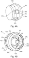
- FIGS 4A and 4B show perspective views of the afterburner system 40 of Figures 2 and 3 without the fuel injector and igniter units 43 and in the non-reheating configuration.
- flap-like doors 42a - 42f are open, and so core exhaust may flow through entrances 45a - 45f into the annular second core flow duct formed between an outer wall 30a and an inner tubular projection 30b of the core plug 30.
- the fuel injectors and igniters 43 are exposed to the diverted portion 27b of the core exhaust flow 201 during normal (non-reheating) operation of the engine.
- they may be concealed from the second core flow duct during normal operation and hence removed from exposure to the diverted portion 27b, but revealed to the second core flow duct in the reheating configuration.
- the fuel injectors and igniters may be hidden behind the doors 42 when the doors are open (e.g. recessed in the inner tubular projection 30b of the core plug 30) to be revealed when the doors are closed. In this way, losses in the diverted portion 27b of the core exhaust flow 201 can be reduced.
- the afterburner system 40 may include one or more flow straighteners located between respective pairs of adjacent doors 42.
- the flow straighteners may, for example, extend in a direction generally aligned with the axis of the engine to better align the direction of the diverted portion 27b of the core exhaust flow 201 with that axis.
- the afterburner system 40 may include a physical flameholder to stabilise the flame.
- a flameholder may be arranged so that it is concealed from the second core flow duct during normal operation, but revealed to the second core flow duct in the reheating configuration.
- the afterburner system 40 can be retro-fitted to existing engines where additional thrust boost is required.
- the afterburner system 40 can be usefully applied to subsonic engines, e.g. to enhance field performance and dash capability in exceptional circumstances, when noise regulations permit.
- gas turbine engines to which the present disclosure may be applied may have alternative configurations.
- such engines may have a different number of interconnecting shafts (e.g. one or three) and/or a different number of compressors and/or turbines and/or a single stage fan.
- the engine may comprise a gearbox provided in the drive train from a turbine to a compressor and/or fan.
Landscapes
- Engineering & Computer Science (AREA)
- Chemical & Material Sciences (AREA)
- Combustion & Propulsion (AREA)
- Mechanical Engineering (AREA)
- General Engineering & Computer Science (AREA)
- Structures Of Non-Positive Displacement Pumps (AREA)
- Exhaust Gas After Treatment (AREA)
Abstract
Description
- The present disclosure relates to a turbofan engine, such as a turbofan engine for use on a supersonic aircraft, and an afterburner system for such an engine.
- There is a growing interest in the development of supersonic aircrafts for civil use. In particular, gas turbine engine systems that effectively provide thrust in subsonic, transonic and supersonic flight regimes, with reduced noise output during certain operations, are of interest.
- A turbofan engine typically comprises, in axial flow series, an air intake, a propulsive fan, one or more compressors, combustion equipment, and one or more turbines. Air entering the intake is accelerated by the fan to produce two air flows: a core flow into the one or more compressors and a bypass flow which passes through a bypass duct and to provide propulsive thrust. The compressed air exhausted from the compressor(s) is directed into the combustion equipment where it is mixed with fuel and the mixture combusted. The resultant hot combustion products then expand through, and thereby drive the turbine(s), before being exhausted as a core exhaust flow to provide further propulsive thrust.
- Afterburning, or re-heating, systems introduce additional fuel into the exhaust flow and ignite it for limited periods. This increase in the temperature of the exhaust flow increases the thrust provided by the engine, and can be particularly beneficially employed during the operation of supersonic engines. However, conventional afterburner systems introduce significant performance penalties, particularly during non-afterburning operations, as they impact the entire exhaust flow. There is a desire then to provide an afterburner system which, during non-afterburning operations, reduces these performance penalties.
- The present disclosure provides a turbofan engine, an afterburner system, a supersonic aircraft, and method of providing a temporary thrust boost in the supersonic aircraft, as set out in the appended claims.
- Accordingly, in a first aspect, there is a turbofan engine having:
- an engine core comprising a compressor, a combustor, a turbine, and a core shaft connecting the turbine to the compressor, and producing a core exhaust flow;
- a fan upstream of the engine core;
- a bypass duct surrounding the engine core and carrying a bypass air flow produced by the fan;
- an exhaust assembly comprising a first exhaust nozzle defining a downstream end of a first core flow duct which receives the core exhaust flow produced by the engine core; and
- an afterburner system comprising:
- a core plug defining a radially inner surface of the first core flow duct;
- a second core flow duct located in the core plug, and having one or more entrances from the first core flow duct for diversion into the second core flow duct of a portion of the core exhaust flow, and further having an exit therefrom for re-joining the diverted portion of the core exhaust flow to the undiverted portion of the core exhaust flow;
- one or more respective doors for the entrances to the second core flow duct, the doors being open during normal operation of the engine but being closable, during a reheat operation, to at least partially block the entrances to the second core flow duct; and
- one or more fuel injectors and one or more respective igniters operable, during the reheat operation, to respectively inject and ignite fuel within the second core flow duct, thereby providing a reheat flow into the core exhaust flow from the exit of the second core flow duct.
- By restricting the generation of the reheat flow to the second core flow duct, pressure losses during normal (i.e. non-afterburning) operation can be reduced, as compared to a conventional afterburner system. In particular, core exhaust flow through the first core flow duct can remain largely unaffected by the reheat equipment (injectors, igniters etc.). However, in addition to the known benefits of an afterburner system, the use of the afterburner system of the first aspect introduces an area change in the hot chute of the turbofan engine (i.e. via the closure of the doors), which can give an additional thrust boost during the engine's cycle. Additionally, reheating is limited to the core flow and therefore the need for high temperature materials in other components (for example the first exhaust nozzle) can be avoided, i.e. because the bypass airflow is not reheated.
- The turbofan engine may have any one or, to the extent that they are compatible, any combination of the following optional features.
- The turbofan engine may be configured for supersonic flight operation.
- The first exhaust nozzle may also define a downstream end of the bypass duct. In this case, the engine may further have an exhaust duct receiving the bypass air flow and the core exhaust flow and exhausting these flows at a second exhaust nozzle. The first exhaust nozzle may then be a mixer nozzle which encourages mixing of the bypass air flow and the core exhaust flow downstream thereof. The mixer nozzle may be a lobed mixer nozzle. The bypass air flow is typically much cooler than the reheated core exhaust flow. As such, the bypass air flow may protect other components, for example the first exhaust nozzle and the second exhaust nozzle, from thermal damage from the reheated flow.
- The or each door may be a covering or flap over the respective entrance of the second core flow duct located upstream of the one or more fuel injectors and igniters. The or each fuel injector and its respective igniter may be a single unit or, alternatively, may be separate units. The or each door may be actively maintained in an open configuration during normal operation, i.e. via one or more mechanisms or, may be configured so as to be held open by exhaust gas pressure.
- Conveniently, wherein the afterburner system may further comprise a fuel-based hydraulic system for actuating the opening and closing of the doors.
- The fuel injectors and igniters may be configured to be concealed from the second core flow duct when the doors are open and revealed to the second core flow duct when the doors are closed. As such, any deleterious flow-disturbing effects of the fuel injectors and igniters during normal (non-reheating) operation can be reduced.
- The second core flow duct may be an annular duct coaxial with the axis of the engine.
- The afterburner system may comprise plural doors circumferentially spaced around the core plug.
- The afterburner system may include flow straighteners located between respective pairs of adjacent doors.
- The doors, when closed, may merely reduce the amount of flow diversion from the second core flow duct to form a purge flow in the second core flow duct. Alternatively, the doors may be configured to completely seal the entrances of the second core flow duct when closed to prevent the flow diversion.
- The afterburner system may be configured to form, downstream of the second core flow duct when the doors are closed, a recirculating airflow. The recirculating airflow may provide a region with a relatively low air speed (in a direction axially away from the core plug) whereupon a more stable flame can be formed during reheat operation. Additionally or alternatively, the afterburner system may further comprise a physical flameholder to stabilise the flame. The flameholder may be configured to be concealed from the second core flow duct when the doors are open and revealed to the second core flow duct when the doors are closed.
- In a second aspect, there is provided an afterburner system, installable downstream of an engine core of a turbofan engine, the system including:
- a core plug defining a radially inner surface of a first core flow duct which receives a core exhaust flow produced by the engine core;
- a second core flow duct located in the core plug, and having one or more entrances from the first core flow duct for diversion into the second core flow duct of a portion of the core exhaust flow, and further having an exit therefrom for re-joining the diverted portion of the core exhaust flow to the undiverted portion of the core exhaust flow;
- one or more respective doors for the entrances to the second core flow duct, the doors being open during normal operation of the engine but being closable, during a reheat operation, to at least partially block the entrances to the second core flow duct; and
- one or more fuel injectors and one or more respective igniters operable, during the reheat operation, to respectively inject and ignite fuel within the second core flow duct, thereby providing a reheat flow into the core exhaust flow from the exit of the second core flow duct.
- The afterburner system of the second aspect may be the afterburner system as referred to in the first aspect, and may have any one or, to the extent that they are compatible, any combination of the optional features related thereto.
- In third aspect, there is provided a supersonic aircraft having one or more turbofan engines according to the first aspect.
- In a fourth aspect, there is provided a method of providing a temporary thrust boost in the supersonic aircraft of the third aspect including the step of:
closing the doors so as to at least partially block the entrances to the second core flow duct. - Advantageously, merely closing the doors can provide a temporary thrust boost by shifting the engine operation point.
- However, the method may have any one or, to the extent that they are compatible, any combination of the following optional features.
- In particular, the method may further include the step of injecting and igniting fuel within the second core flow duct, thereby providing a reheated airflow and a temporary thrust boost. The closing, and injecting and igniting steps may be performed in either order. Generally, the step of closing the doors is performed before the step of injecting and igniting the fuel. Typically the temporary thrust boost provided by the reheated airflow is significantly greater than that provided by merely closing the doors.
- The method may further include the step, performed after the closing step, of: re-opening the doors. When the method includes the step of injecting and igniting fuel within the second core flow duct, then the method may further include the step, performed after the injecting and igniting of: ending the injection and ignition of fuel within the second core flow duct. The ending the injection and ignition, and re-opening steps may be performed in either order. Generally, the step of ending the injection and ignition is performed before the step of re-opening the doors. These steps may be performed so as to place the engine to a more fuel efficient configuration, e.g. when afterburning is not required.
- The temporary thrust boost may be performed as part of a trans-sonic thrust operation. Alternatively, or additionally, the temporary thrust boost may be performed during either or both of a take-off operation and a climbing operation.
- Embodiments of the disclosure will now be described by way of example with reference to the accompanying drawings in which:
-
Figure 1 is a sectional side view of a turbofan engine; -
Figure 2 is a sectional side view of an afterburner system in a non-reheating configuration; -
Figure 3 is a sectional side view of the afterburner system in a reheating configured; and -
Figures 4A and 4B provide respective perspective views of the afterburner system in a non-reheating configuration. - Aspects and embodiments of the present disclosure will now be discussed with reference to the accompanying figures. Further aspects and embodiments will be apparent to those skilled in the art.
-
Figure 1 shows a longitudinal cross-section through aturbofan engine 1 for a civil supersonic aircraft. Theturbofan engine 1 comprises anengine intake 2, amulti-stage fan 3, aprimary flow channel 6 that leads through an engine core, asecondary flow channel 22 that leads past the engine core, alobed mixer nozzle 23, anexhaust duct 24, and anexhaust nozzle 20 into which a thrust reverser (not shown) can be integrated. - The
turbofan engine 1 has a machine axis orengine centre line 8. Themachine axis 8 defines an axial direction of the turbofan engine. A radial direction of the turbofan engine extends perpendicularly to the axial direction. - The engine core comprises in a per se known manner a
compressor 7, acombustion chamber 11 and aturbine pressure compressor 7. A low-pressure compressor is formed by the areas of themulti-stage fan rotor 3 that are located close to the hub. The turbine that is arranged behind thecombustion chamber 11 comprises a high-pressure turbine 91 and a low-pressure turbine 92. The high-pressure turbine 91 drives a high-pressure shaft 81 that connects the high-pressure turbine 91 to the high-pressure compressor 7. The low-pressure turbine 92 drives a low-pressure shaft 82 that connects the low-pressure turbine 92 to themulti-stage fan 3. - The
turbofan engine 1 is arranged inside anengine nacelle 10. It is connected to the aircraft fuselage, for example via a pylon. - The
engine intake 2 forms a supersonic air inlet and is correspondingly provided and suitable for slowing down the inflowing air to velocities of below Ma 1.0. InFigure 1 , but not necessarily, the engine intake is bevelled, forming an angle α, wherein the upper edge projects with respect to the lower edge. This serves for a better distribution of compression shocks as they occur in supersonic flight. However, in principle the engine intake can be formed in a straight manner, i.e. with an angle α of 90°, or a different angle than the one shown. - The
engine intake 2 can have an interior cladding of a sound-absorbingmaterial 21. This serves for reducing engine noise. - The
fan 3 can be formed as a multi-stage fan, in the shown exemplary embodiment as a double-stage fan. Accordingly, themulti-stage fan 3 comprises afan rotor 31 and afan stator 32 that form a first, frontal fan stage, as well as afan rotor 33 and afan stator fan 3 is provided with anose cone 35. Thefan rotors fan stator 32 of the frontal fan stage comprises a plurality of stator blades that are mounted in afan housing 37. The fan stator of the rear fan stage is split and is formed by aguide baffle 34a that is formed at the entry of theprimary flow channel 6, and formed by aguide baffle 34b that is formed at the entry of the secondary flow channel 5. Thefan rotors - Behind the
fan rotor 33, the flow channel through thefan 3 is divided into theprimary flow channel 6 and thesecondary flow channel 22. Thesecondary flow channel 22 is also referred to as the bypass flow channel or the bypass duct. - Behind the engine core, the
core exhaust flow 201 from theprimary flow channel 6 and the bypass air flow from thebypass duct 22 are mixed by themixer nozzle 23. Further, acore plug 30 is inserted behind the low-pressure turbine 92 to realize the desired cross sections of the core exhaust flow. Theexhaust nozzle 20 can be a variable area exhaust nozzle. The core plug 30 includes anafterburner system 40 which is described in more detail below. The afterburner can be used as part of a trans-sonic thrust operation of the engine. Alternatively, or additionally, it can be used during a take-off operation and/or a climbing operation. -
Figure 2 shows a sectional side of theafterburner system 40 in a non-reheating (normal engine operation) configuration. Thecore exhaust flow 201 from the low-pressure turbine 92 enters an annular firstcore flow duct 44 which is bounded on its radially outer side by themixer nozzle 23 and on its radially inner side by the outer surface of thecore plug 30. Anundiverted portion 27a of thecore exhaust flow 201 travels through the first flow duct. As it does so, radially outer parts of theundiverted portion 27a mix with radially inner parts of thebypass air flow 202 to form amixed flow 203. By contrast, radially inner parts of theundiverted portion 27a continue through the firstcore flow duct 44 to arrive at the downstream end of the outer surface of thecore plug 30. In parallel, anotherportion 27b of thecore exhaust flow 201 is diverted from thefirst flow duct 44 through a circumferential row ofentrances 45 formed in the outer surface of thecore plug 30 into an annular secondcore exhaust duct 41, located within thecore plug 30. Theseentrances 45 haverespective doors 42 which are shown open inFigure 2 . Within the secondcore exhaust duct 41 are one or more fuel injector andigniter units 43, which in normal (non-reheating) engine operation are not used to inject and ignite fuel. Typically plural such units are circumferentially arranged around the duct. The number and/or position of thedoors 42 can be selected in order to reduce noise generation by the afterburner system. - The diverted
portion 27b of the core exhaust flow re-joins the radially inner parts of theundiverted portion 27a downstream of the fuel injector andigniter units 43 as a reformedcore exhaust flow 204. This then exits themixer nozzle 23 for onward flow through theexhaust duct 24 to the exhaust nozzle 20along with themixed flow 203 and the rest of thebypass airflow 202. Therefore, in non-reheating operation, the flow of core exhaust through theafterburner system 40 incurs few pressure losses. - The
doors 42 may be held open by the exhaust gas pressure only, or may be actively held in an open configuration via actuation means, whether that be mechanical, electrical, or hydraulic (e.g. fuel-based hydraulic). -
Figure 3 is then a sectional view of theafterburner system 40 in a reheating configuration. In contrast to the configuration shown inFigure 2 , thedoors 42 are now closed to block the entrances to the to the secondcore flow duct 41. As a result, thecore exhaust flow 201 passes undiverted around the outside of thecore plug 30 within the firstcore flow duct 44. - The second
core exhaust duct 41 provides an annular cavity which encourages a recirculating flow to form downstream of thecore plug 30. This in turn creates a region of low speed air (in the axial direction 8) where a stable flame can form. - Within the second
core exhaust duct 41, the fuel injectors of theunits 43 inject fuel, which is ignited by the igniters. The result is aflame 302 and areheat flow 303 which provides further thrust to the engine. Of note is that thecore exhaust flow 201 exits theafterburner system 40 with a narrower cross-sectional area than the re-formedcore exhaust flow 204 in the non-reheating configuration. This narrower cross-sectional area can also impart additional thrust to the engine by shifting the engine operation point. Moreover the velocity of thecore exhaust flow 201 increases due to the decrease in cross-sectional area. - Instead of closing the
doors 42 to completely block the entrances to the secondcore exhaust duct 41, an option is to close them in the reheating configuration such that the entrances are only partially blocked. In particular, a small amount ofcore exhaust flow 201 may be allowed to enter the secondcore exhaust duct 41 to act as a purge flow therethrough. - As will be appreciated, the reheat flow in this system is limited to the core exhaust flow region of the engine. This leaves the bypass air flow largely unaffected by the increased temperatures of the core exhaust flow during reheating. The colder outer stream can therefore act as protection for the engine aft nacelle (including, for example a thrust reverser unit and the exhaust nozzle 20). The cooler bypass flow therefore allows lower cost and lighter materials to be employed for these components, whereas a conventional reheat system would require high temperature capability and cooling.
-
Figures 4A and 4B show perspective views of theafterburner system 40 ofFigures 2 and3 without the fuel injector andigniter units 43 and in the non-reheating configuration. As such, flap-like doors 42a - 42f are open, and so core exhaust may flow throughentrances 45a - 45f into the annular second core flow duct formed between anouter wall 30a and an innertubular projection 30b of thecore plug 30. - In the examples discussed above, the fuel injectors and
igniters 43 are exposed to the divertedportion 27b of thecore exhaust flow 201 during normal (non-reheating) operation of the engine. However, in other examples they may be concealed from the second core flow duct during normal operation and hence removed from exposure to the divertedportion 27b, but revealed to the second core flow duct in the reheating configuration. For example, the fuel injectors and igniters may be hidden behind thedoors 42 when the doors are open (e.g. recessed in the innertubular projection 30b of the core plug 30) to be revealed when the doors are closed. In this way, losses in the divertedportion 27b of thecore exhaust flow 201 can be reduced. - Although not shown in the examples above, the
afterburner system 40 may include one or more flow straighteners located between respective pairs ofadjacent doors 42. The flow straighteners may, for example, extend in a direction generally aligned with the axis of the engine to better align the direction of the divertedportion 27b of thecore exhaust flow 201 with that axis. - Although also not shown in the examples above, the
afterburner system 40 may include a physical flameholder to stabilise the flame. Like the fuel injectors andigniters 43, such a flameholder may be arranged so that it is concealed from the second core flow duct during normal operation, but revealed to the second core flow duct in the reheating configuration. - The
afterburner system 40 can be retro-fitted to existing engines where additional thrust boost is required. - Although described above in relation to a supersonic gas turbine engine, the
afterburner system 40 can be usefully applied to subsonic engines, e.g. to enhance field performance and dash capability in exceptional circumstances, when noise regulations permit. - Other gas turbine engines to which the present disclosure may be applied may have alternative configurations. By way of example such engines may have a different number of interconnecting shafts (e.g. one or three) and/or a different number of compressors and/or turbines and/or a single stage fan. Further the engine may comprise a gearbox provided in the drive train from a turbine to a compressor and/or fan.
- It will be understood that the invention is not limited to the embodiments above-described and various modifications and improvements can be made without departing from the concepts described herein within the scope of the following claims. Except where mutually exclusive, any of the features may be employed separately or in combination with any other features and the disclosure extends to and includes all combinations and sub-combinations of one or more features described herein.
Claims (15)
- A turbofan engine having:an engine core comprising a compressor (7), a combustor (11), a turbine (91, 92), and a core shaft connecting the turbine to the compressor, and producing a core exhaust flow;a fan upstream of the engine core;a bypass duct (22) surrounding the engine core and carrying a bypass airflow produced by the fan;an exhaust assembly comprising a first exhaust nozzle (23) defining a downstream end of a first core flow duct which receives the core exhaust flow produced by the engine core; andan afterburner system comprising:a core plug (30) defining a radially inner surface of the first core flow duct (44);a second core flow duct (41) located in the core plug (30), and having one or more entrances from the first core flow duct for diversion into the second core flow duct of a portion of the core exhaust flow, and further having an exit therefrom for re-joining the diverted portion of the core exhaust flow to the undiverted portion of the core exhaust flow;one or more respective doors (42) for the entrances to the second core flow duct (41), the doors being open during normal operation of the engine but being closable, during a reheat operation, to at least partially block the entrances to the second core flow duct; andone or more fuel injectors and one or more respective igniters (43) operable, during the reheat operation, to respectively inject and ignite fuel within the second core flow duct, thereby providing a reheat flow (303) into the core exhaust flow from the exit of the second core flow duct.
- The turbofan engine according to claim 1 wherein the first exhaust nozzle also defines a downstream end of the bypass duct, and the engine further has an exhaust duct (24) receiving the bypass air flow and the core exhaust flow and exhausting these flows at a second exhaust nozzle.
- The turbofan engine according to claim 2 wherein the first exhaust nozzle (23) is a mixer nozzle which encourages mixing of the bypass air flow and the core exhaust flow downstream thereof.
- The turbofan engine according to any preceding claim, wherein the afterburner system further comprises a fuel-based hydraulic system for actuating the opening and closing of the doors.
- The turbofan engine according to any preceding claim, wherein the fuel injectors and igniters are configured to be concealed from the second core flow duct (41) when the doors are open and revealed to the second core flow duct (41) when the doors are closed.
- The turbofan engine according to any preceding claim, wherein the second core flow duct is an annular duct coaxial with the axis of the engine.
- The turbofan engine according to any preceding claim, wherein the afterburner system comprises plural doors (42a - 42f) circumferentially spaced around the core plug.
- The turbofan engine of claim 7, wherein the afterburner system further comprises flow straighteners located between respective pairs of adjacent doors.
- The turbofan engine according to any preceding claim, wherein the doors, when closed, reduce the amount of flow diversion from the second core flow duct to form a purge flow in the second core flow duct.
- An afterburner system (40), installable downstream of an engine core of a turbofan engine, the system including:a core plug (30) defining a radially inner surface of a first core flow duct (44) which receives a core exhaust flow produced by the engine core;a second core flow duct (41) located in the core plug (30), and having one or more entrances from the first core flow duct for diversion into the second core flow duct of a portion of the core exhaust flow, and further having an exit therefrom for re-joining the diverted portion of the core exhaust flow to the undiverted portion of the core exhaust flow;one or more respective doors (42) for the entrances to the second core flow duct (41), the doors being open during normal operation of the engine but being closable, during a reheat operation, to at least partially block the entrances to the second core flow duct; andone or more fuel injectors and one or more respective igniters (43) operable, during the reheat operation, to respectively inject and ignite fuel within the second core flow duct, thereby providing a reheat flow (303) into the core exhaust flow from the exit of the second core flow duct.
- A supersonic aircraft having one or more turbofan engines according to any one of claims 1 to 9.
- A method of providing a temporary thrust boost in the supersonic aircraft of claim 11 including the step of:
closing the doors so as to at least partially block the entrances to the or each second core flow duct. - The method of claim 12, further including the step of:
injecting and igniting fuel within the or each second core flow duct, thereby providing a reheated airflow (303) and a temporary thrust boost. - The method of claim 13, further including the steps, performed after providing the temporary thrust boost, of:ending the injection and ignition of fuel within the or each second core flow duct; andre-opening the doors.
- The method of any one of claims 12 to 15, wherein the temporary thrust boost is performed as part of a trans-sonic thrust flight operation of the aircraft.
Applications Claiming Priority (2)
| Application Number | Priority Date | Filing Date | Title |
|---|---|---|---|
| GR20180100467 | 2018-10-12 | ||
| GBGB1819748.3A GB201819748D0 (en) | 2018-10-12 | 2018-12-04 | Afterburner system |
Publications (2)
| Publication Number | Publication Date |
|---|---|
| EP3636906A1 true EP3636906A1 (en) | 2020-04-15 |
| EP3636906B1 EP3636906B1 (en) | 2022-11-02 |
Family
ID=65024780
Family Applications (1)
| Application Number | Title | Priority Date | Filing Date |
|---|---|---|---|
| EP19197014.4A Active EP3636906B1 (en) | 2018-10-12 | 2019-09-12 | Afterburner system |
Country Status (3)
| Country | Link |
|---|---|
| US (1) | US11008976B2 (en) |
| EP (1) | EP3636906B1 (en) |
| GB (1) | GB201819748D0 (en) |
Cited By (1)
| Publication number | Priority date | Publication date | Assignee | Title |
|---|---|---|---|---|
| WO2021249184A1 (en) * | 2020-06-08 | 2021-12-16 | 清华大学 | Two-duct turbojet engine with bearing cooling function |
Families Citing this family (8)
| Publication number | Priority date | Publication date | Assignee | Title |
|---|---|---|---|---|
| GB2610567A (en) | 2021-09-08 | 2023-03-15 | Rolls Royce Plc | An improved gas turbine engine |
| GB2610572A (en) | 2021-09-08 | 2023-03-15 | Rolls Royce Plc | An improved gas turbine engine |
| GB2610566A (en) * | 2021-09-08 | 2023-03-15 | Rolls Royce Plc | An improved gas turbine engine |
| GB2610568A (en) | 2021-09-08 | 2023-03-15 | Rolls Royce Plc | An improved gas turbine engine |
| GB2610571A (en) | 2021-09-08 | 2023-03-15 | Rolls Royce Plc | An improved gas turbine engine |
| GB2610565A (en) | 2021-09-08 | 2023-03-15 | Rolls Royce Plc | An improved gas turbine engine |
| GB2610569A (en) | 2021-09-08 | 2023-03-15 | Rolls Royce Plc | An improved gas turbine engine |
| GB202210142D0 (en) * | 2022-07-11 | 2022-08-24 | Rolls Royce Plc | Gas turbine engine |
Citations (5)
| Publication number | Priority date | Publication date | Assignee | Title |
|---|---|---|---|---|
| US2913874A (en) * | 1955-03-30 | 1959-11-24 | Gen Electric | Tailpipe thrust augmentor |
| US2929203A (en) * | 1956-08-31 | 1960-03-22 | Westinghouse Electric Corp | Afterburning bypass aviation turbojet engine |
| GB1273017A (en) * | 1968-10-02 | 1972-05-03 | Snecma | Improvements in or relating to burners for reheat combustion chambers |
| US4798048A (en) * | 1987-12-21 | 1989-01-17 | United Technologies Corporation | Augmentor pilot |
| US20030150214A1 (en) * | 2002-01-09 | 2003-08-14 | Jean-Pierre Lair | Variable area plug nozzle |
Family Cites Families (7)
| Publication number | Priority date | Publication date | Assignee | Title |
|---|---|---|---|---|
| US3331204A (en) | 1966-02-07 | 1967-07-18 | Gen Electric | Standby afterburner operation system |
| FR1525092A (en) | 1967-01-23 | 1968-05-17 | Snecma | Hot gas flow and cold air flow turbo-reactor |
| GB1503425A (en) | 1976-08-04 | 1978-03-08 | Hallowell E | Gas turbine ducted fan jet engines for supersonic flight |
| US5385015A (en) * | 1993-07-02 | 1995-01-31 | United Technologies Corporation | Augmentor burner |
| FR2858661B1 (en) | 2003-08-05 | 2005-10-07 | Snecma Moteurs | POST-COMBUSTION DEVICE |
| US7251941B2 (en) | 2004-03-10 | 2007-08-07 | General Electric Company | Ablative afterburner |
| US9115897B2 (en) * | 2008-09-04 | 2015-08-25 | United Technologies Corporation | Gas turbine engine systems and methods involving enhanced fuel dispersion |
-
2018
- 2018-12-04 GB GBGB1819748.3A patent/GB201819748D0/en not_active Ceased
-
2019
- 2019-09-12 EP EP19197014.4A patent/EP3636906B1/en active Active
- 2019-09-19 US US16/575,555 patent/US11008976B2/en active Active
Patent Citations (5)
| Publication number | Priority date | Publication date | Assignee | Title |
|---|---|---|---|---|
| US2913874A (en) * | 1955-03-30 | 1959-11-24 | Gen Electric | Tailpipe thrust augmentor |
| US2929203A (en) * | 1956-08-31 | 1960-03-22 | Westinghouse Electric Corp | Afterburning bypass aviation turbojet engine |
| GB1273017A (en) * | 1968-10-02 | 1972-05-03 | Snecma | Improvements in or relating to burners for reheat combustion chambers |
| US4798048A (en) * | 1987-12-21 | 1989-01-17 | United Technologies Corporation | Augmentor pilot |
| US20030150214A1 (en) * | 2002-01-09 | 2003-08-14 | Jean-Pierre Lair | Variable area plug nozzle |
Cited By (1)
| Publication number | Priority date | Publication date | Assignee | Title |
|---|---|---|---|---|
| WO2021249184A1 (en) * | 2020-06-08 | 2021-12-16 | 清华大学 | Two-duct turbojet engine with bearing cooling function |
Also Published As
| Publication number | Publication date |
|---|---|
| US20200116359A1 (en) | 2020-04-16 |
| US11008976B2 (en) | 2021-05-18 |
| EP3636906B1 (en) | 2022-11-02 |
| GB201819748D0 (en) | 2019-01-16 |
Similar Documents
| Publication | Publication Date | Title |
|---|---|---|
| US11008976B2 (en) | Afterburner system for turbofan engine | |
| EP1939438B1 (en) | Duct burning mixed flow turbofan | |
| CN109028146B (en) | Hybrid combustor assembly and method of operation | |
| CN109028142B (en) | Propulsion system and method of operating the same | |
| CA2452972C (en) | Methods and apparatus for generating gas turbine engine thrust | |
| EP1655474B1 (en) | Thrust vectoring aft flade engine | |
| EP1533510B1 (en) | Two-spool variable cycle gas turbine engine | |
| EP1892399A2 (en) | Aero engine bleed valve | |
| EP1527997A2 (en) | Flade gas turbine engine with fixed geometry inlet | |
| EP2472089B1 (en) | Flade discharge in 2-d exhaust nozzle | |
| EP1433946A1 (en) | Combined cycle pulse detonation turbine engine | |
| US5311735A (en) | Ramjet bypass duct and preburner configuration | |
| US20130336759A1 (en) | Turbomachine flow control device | |
| US20180356099A1 (en) | Bulk swirl rotating detonation propulsion system | |
| EP1803920A2 (en) | Fixed nozzle thrust augmentation system | |
| US10443493B2 (en) | Exhaust mixer for wave rotor assembly | |
| US11053886B2 (en) | Supersonic aircraft turbofan | |
| EP1607610A1 (en) | Two-dimensional vectorable single expansion ramp nozzle | |
| CN117346181A (en) | Burner with reverse dilution air introduction | |
| EP3473841B1 (en) | Turbofan engine | |
| Beheim et al. | Subsonic and Supersonic Propulsion |
Legal Events
| Date | Code | Title | Description |
|---|---|---|---|
| PUAI | Public reference made under article 153(3) epc to a published international application that has entered the european phase |
Free format text: ORIGINAL CODE: 0009012 |
|
| STAA | Information on the status of an ep patent application or granted ep patent |
Free format text: STATUS: THE APPLICATION HAS BEEN PUBLISHED |
|
| AK | Designated contracting states |
Kind code of ref document: A1 Designated state(s): AL AT BE BG CH CY CZ DE DK EE ES FI FR GB GR HR HU IE IS IT LI LT LU LV MC MK MT NL NO PL PT RO RS SE SI SK SM TR |
|
| AX | Request for extension of the european patent |
Extension state: BA ME |
|
| STAA | Information on the status of an ep patent application or granted ep patent |
Free format text: STATUS: REQUEST FOR EXAMINATION WAS MADE |
|
| 17P | Request for examination filed |
Effective date: 20201007 |
|
| RBV | Designated contracting states (corrected) |
Designated state(s): AL AT BE BG CH CY CZ DE DK EE ES FI FR GB GR HR HU IE IS IT LI LT LU LV MC MK MT NL NO PL PT RO RS SE SI SK SM TR |
|
| GRAP | Despatch of communication of intention to grant a patent |
Free format text: ORIGINAL CODE: EPIDOSNIGR1 |
|
| STAA | Information on the status of an ep patent application or granted ep patent |
Free format text: STATUS: GRANT OF PATENT IS INTENDED |
|
| GRAS | Grant fee paid |
Free format text: ORIGINAL CODE: EPIDOSNIGR3 |
|
| INTG | Intention to grant announced |
Effective date: 20220727 |
|
| GRAA | (expected) grant |
Free format text: ORIGINAL CODE: 0009210 |
|
| STAA | Information on the status of an ep patent application or granted ep patent |
Free format text: STATUS: THE PATENT HAS BEEN GRANTED |
|
| AK | Designated contracting states |
Kind code of ref document: B1 Designated state(s): AL AT BE BG CH CY CZ DE DK EE ES FI FR GB GR HR HU IE IS IT LI LT LU LV MC MK MT NL NO PL PT RO RS SE SI SK SM TR |
|
| REG | Reference to a national code |
Ref country code: GB Ref legal event code: FG4D |
|
| REG | Reference to a national code |
Ref country code: CH Ref legal event code: EP Ref country code: AT Ref legal event code: REF Ref document number: 1528919 Country of ref document: AT Kind code of ref document: T Effective date: 20221115 |
|
| REG | Reference to a national code |
Ref country code: DE Ref legal event code: R096 Ref document number: 602019021355 Country of ref document: DE |
|
| REG | Reference to a national code |
Ref country code: IE Ref legal event code: FG4D |
|
| REG | Reference to a national code |
Ref country code: LT Ref legal event code: MG9D |
|
| REG | Reference to a national code |
Ref country code: NL Ref legal event code: MP Effective date: 20221102 |
|
| REG | Reference to a national code |
Ref country code: AT Ref legal event code: MK05 Ref document number: 1528919 Country of ref document: AT Kind code of ref document: T Effective date: 20221102 |
|
| PG25 | Lapsed in a contracting state [announced via postgrant information from national office to epo] |
Ref country code: SE Free format text: LAPSE BECAUSE OF FAILURE TO SUBMIT A TRANSLATION OF THE DESCRIPTION OR TO PAY THE FEE WITHIN THE PRESCRIBED TIME-LIMIT Effective date: 20221102 Ref country code: PT Free format text: LAPSE BECAUSE OF FAILURE TO SUBMIT A TRANSLATION OF THE DESCRIPTION OR TO PAY THE FEE WITHIN THE PRESCRIBED TIME-LIMIT Effective date: 20230302 Ref country code: NO Free format text: LAPSE BECAUSE OF FAILURE TO SUBMIT A TRANSLATION OF THE DESCRIPTION OR TO PAY THE FEE WITHIN THE PRESCRIBED TIME-LIMIT Effective date: 20230202 Ref country code: LT Free format text: LAPSE BECAUSE OF FAILURE TO SUBMIT A TRANSLATION OF THE DESCRIPTION OR TO PAY THE FEE WITHIN THE PRESCRIBED TIME-LIMIT Effective date: 20221102 Ref country code: FI Free format text: LAPSE BECAUSE OF FAILURE TO SUBMIT A TRANSLATION OF THE DESCRIPTION OR TO PAY THE FEE WITHIN THE PRESCRIBED TIME-LIMIT Effective date: 20221102 Ref country code: ES Free format text: LAPSE BECAUSE OF FAILURE TO SUBMIT A TRANSLATION OF THE DESCRIPTION OR TO PAY THE FEE WITHIN THE PRESCRIBED TIME-LIMIT Effective date: 20221102 Ref country code: AT Free format text: LAPSE BECAUSE OF FAILURE TO SUBMIT A TRANSLATION OF THE DESCRIPTION OR TO PAY THE FEE WITHIN THE PRESCRIBED TIME-LIMIT Effective date: 20221102 |
|
| PG25 | Lapsed in a contracting state [announced via postgrant information from national office to epo] |
Ref country code: RS Free format text: LAPSE BECAUSE OF FAILURE TO SUBMIT A TRANSLATION OF THE DESCRIPTION OR TO PAY THE FEE WITHIN THE PRESCRIBED TIME-LIMIT Effective date: 20221102 Ref country code: PL Free format text: LAPSE BECAUSE OF FAILURE TO SUBMIT A TRANSLATION OF THE DESCRIPTION OR TO PAY THE FEE WITHIN THE PRESCRIBED TIME-LIMIT Effective date: 20221102 Ref country code: LV Free format text: LAPSE BECAUSE OF FAILURE TO SUBMIT A TRANSLATION OF THE DESCRIPTION OR TO PAY THE FEE WITHIN THE PRESCRIBED TIME-LIMIT Effective date: 20221102 Ref country code: IS Free format text: LAPSE BECAUSE OF FAILURE TO SUBMIT A TRANSLATION OF THE DESCRIPTION OR TO PAY THE FEE WITHIN THE PRESCRIBED TIME-LIMIT Effective date: 20230302 Ref country code: HR Free format text: LAPSE BECAUSE OF FAILURE TO SUBMIT A TRANSLATION OF THE DESCRIPTION OR TO PAY THE FEE WITHIN THE PRESCRIBED TIME-LIMIT Effective date: 20221102 Ref country code: GR Free format text: LAPSE BECAUSE OF FAILURE TO SUBMIT A TRANSLATION OF THE DESCRIPTION OR TO PAY THE FEE WITHIN THE PRESCRIBED TIME-LIMIT Effective date: 20230203 |
|
| PG25 | Lapsed in a contracting state [announced via postgrant information from national office to epo] |
Ref country code: NL Free format text: LAPSE BECAUSE OF FAILURE TO SUBMIT A TRANSLATION OF THE DESCRIPTION OR TO PAY THE FEE WITHIN THE PRESCRIBED TIME-LIMIT Effective date: 20221102 |
|
| P01 | Opt-out of the competence of the unified patent court (upc) registered |
Effective date: 20230528 |
|
| PG25 | Lapsed in a contracting state [announced via postgrant information from national office to epo] |
Ref country code: SM Free format text: LAPSE BECAUSE OF FAILURE TO SUBMIT A TRANSLATION OF THE DESCRIPTION OR TO PAY THE FEE WITHIN THE PRESCRIBED TIME-LIMIT Effective date: 20221102 Ref country code: RO Free format text: LAPSE BECAUSE OF FAILURE TO SUBMIT A TRANSLATION OF THE DESCRIPTION OR TO PAY THE FEE WITHIN THE PRESCRIBED TIME-LIMIT Effective date: 20221102 Ref country code: EE Free format text: LAPSE BECAUSE OF FAILURE TO SUBMIT A TRANSLATION OF THE DESCRIPTION OR TO PAY THE FEE WITHIN THE PRESCRIBED TIME-LIMIT Effective date: 20221102 Ref country code: DK Free format text: LAPSE BECAUSE OF FAILURE TO SUBMIT A TRANSLATION OF THE DESCRIPTION OR TO PAY THE FEE WITHIN THE PRESCRIBED TIME-LIMIT Effective date: 20221102 Ref country code: CZ Free format text: LAPSE BECAUSE OF FAILURE TO SUBMIT A TRANSLATION OF THE DESCRIPTION OR TO PAY THE FEE WITHIN THE PRESCRIBED TIME-LIMIT Effective date: 20221102 |
|
| REG | Reference to a national code |
Ref country code: DE Ref legal event code: R097 Ref document number: 602019021355 Country of ref document: DE |
|
| PG25 | Lapsed in a contracting state [announced via postgrant information from national office to epo] |
Ref country code: SK Free format text: LAPSE BECAUSE OF FAILURE TO SUBMIT A TRANSLATION OF THE DESCRIPTION OR TO PAY THE FEE WITHIN THE PRESCRIBED TIME-LIMIT Effective date: 20221102 Ref country code: AL Free format text: LAPSE BECAUSE OF FAILURE TO SUBMIT A TRANSLATION OF THE DESCRIPTION OR TO PAY THE FEE WITHIN THE PRESCRIBED TIME-LIMIT Effective date: 20221102 |
|
| PLBE | No opposition filed within time limit |
Free format text: ORIGINAL CODE: 0009261 |
|
| STAA | Information on the status of an ep patent application or granted ep patent |
Free format text: STATUS: NO OPPOSITION FILED WITHIN TIME LIMIT |
|
| 26N | No opposition filed |
Effective date: 20230803 |
|
| PG25 | Lapsed in a contracting state [announced via postgrant information from national office to epo] |
Ref country code: SI Free format text: LAPSE BECAUSE OF FAILURE TO SUBMIT A TRANSLATION OF THE DESCRIPTION OR TO PAY THE FEE WITHIN THE PRESCRIBED TIME-LIMIT Effective date: 20221102 |
|
| REG | Reference to a national code |
Ref country code: CH Ref legal event code: PL |
|
| PG25 | Lapsed in a contracting state [announced via postgrant information from national office to epo] |
Ref country code: LU Free format text: LAPSE BECAUSE OF NON-PAYMENT OF DUE FEES Effective date: 20230912 |
|
| REG | Reference to a national code |
Ref country code: BE Ref legal event code: MM Effective date: 20230930 |
|
| PG25 | Lapsed in a contracting state [announced via postgrant information from national office to epo] |
Ref country code: LU Free format text: LAPSE BECAUSE OF NON-PAYMENT OF DUE FEES Effective date: 20230912 Ref country code: IT Free format text: LAPSE BECAUSE OF FAILURE TO SUBMIT A TRANSLATION OF THE DESCRIPTION OR TO PAY THE FEE WITHIN THE PRESCRIBED TIME-LIMIT Effective date: 20221102 Ref country code: MC Free format text: LAPSE BECAUSE OF FAILURE TO SUBMIT A TRANSLATION OF THE DESCRIPTION OR TO PAY THE FEE WITHIN THE PRESCRIBED TIME-LIMIT Effective date: 20221102 |
|
| REG | Reference to a national code |
Ref country code: IE Ref legal event code: MM4A |
|
| PG25 | Lapsed in a contracting state [announced via postgrant information from national office to epo] |
Ref country code: IE Free format text: LAPSE BECAUSE OF NON-PAYMENT OF DUE FEES Effective date: 20230912 |
|
| PG25 | Lapsed in a contracting state [announced via postgrant information from national office to epo] |
Ref country code: CH Free format text: LAPSE BECAUSE OF NON-PAYMENT OF DUE FEES Effective date: 20230930 |
|
| PG25 | Lapsed in a contracting state [announced via postgrant information from national office to epo] |
Ref country code: IE Free format text: LAPSE BECAUSE OF NON-PAYMENT OF DUE FEES Effective date: 20230912 Ref country code: CH Free format text: LAPSE BECAUSE OF NON-PAYMENT OF DUE FEES Effective date: 20230930 |
|
| PG25 | Lapsed in a contracting state [announced via postgrant information from national office to epo] |
Ref country code: BE Free format text: LAPSE BECAUSE OF NON-PAYMENT OF DUE FEES Effective date: 20230930 |
|
| PG25 | Lapsed in a contracting state [announced via postgrant information from national office to epo] |
Ref country code: BG Free format text: LAPSE BECAUSE OF FAILURE TO SUBMIT A TRANSLATION OF THE DESCRIPTION OR TO PAY THE FEE WITHIN THE PRESCRIBED TIME-LIMIT Effective date: 20221102 |
|
| PG25 | Lapsed in a contracting state [announced via postgrant information from national office to epo] |
Ref country code: BG Free format text: LAPSE BECAUSE OF FAILURE TO SUBMIT A TRANSLATION OF THE DESCRIPTION OR TO PAY THE FEE WITHIN THE PRESCRIBED TIME-LIMIT Effective date: 20221102 |
|
| PG25 | Lapsed in a contracting state [announced via postgrant information from national office to epo] |
Ref country code: CY Free format text: LAPSE BECAUSE OF FAILURE TO SUBMIT A TRANSLATION OF THE DESCRIPTION OR TO PAY THE FEE WITHIN THE PRESCRIBED TIME-LIMIT; INVALID AB INITIO Effective date: 20190912 |
|
| PG25 | Lapsed in a contracting state [announced via postgrant information from national office to epo] |
Ref country code: HU Free format text: LAPSE BECAUSE OF FAILURE TO SUBMIT A TRANSLATION OF THE DESCRIPTION OR TO PAY THE FEE WITHIN THE PRESCRIBED TIME-LIMIT; INVALID AB INITIO Effective date: 20190912 |
|
| PGFP | Annual fee paid to national office [announced via postgrant information from national office to epo] |
Ref country code: DE Payment date: 20250926 Year of fee payment: 7 |
|
| PGFP | Annual fee paid to national office [announced via postgrant information from national office to epo] |
Ref country code: GB Payment date: 20250923 Year of fee payment: 7 |
|
| PGFP | Annual fee paid to national office [announced via postgrant information from national office to epo] |
Ref country code: FR Payment date: 20250925 Year of fee payment: 7 |
|
| PG25 | Lapsed in a contracting state [announced via postgrant information from national office to epo] |
Ref country code: TR Free format text: LAPSE BECAUSE OF FAILURE TO SUBMIT A TRANSLATION OF THE DESCRIPTION OR TO PAY THE FEE WITHIN THE PRESCRIBED TIME-LIMIT Effective date: 20221102 |