EP3636890A1 - Exhaust gas purification system - Google Patents
Exhaust gas purification system Download PDFInfo
- Publication number
- EP3636890A1 EP3636890A1 EP18820710.4A EP18820710A EP3636890A1 EP 3636890 A1 EP3636890 A1 EP 3636890A1 EP 18820710 A EP18820710 A EP 18820710A EP 3636890 A1 EP3636890 A1 EP 3636890A1
- Authority
- EP
- European Patent Office
- Prior art keywords
- exhaust gas
- reducing agent
- catalyst
- dpf
- scr catalyst
- Prior art date
- Legal status (The legal status is an assumption and is not a legal conclusion. Google has not performed a legal analysis and makes no representation as to the accuracy of the status listed.)
- Withdrawn
Links
Images

Classifications
-
- B—PERFORMING OPERATIONS; TRANSPORTING
- B01—PHYSICAL OR CHEMICAL PROCESSES OR APPARATUS IN GENERAL
- B01J—CHEMICAL OR PHYSICAL PROCESSES, e.g. CATALYSIS OR COLLOID CHEMISTRY; THEIR RELEVANT APPARATUS
- B01J23/00—Catalysts comprising metals or metal oxides or hydroxides, not provided for in group B01J21/00
- B01J23/002—Mixed oxides other than spinels, e.g. perovskite
-
- F—MECHANICAL ENGINEERING; LIGHTING; HEATING; WEAPONS; BLASTING
- F01—MACHINES OR ENGINES IN GENERAL; ENGINE PLANTS IN GENERAL; STEAM ENGINES
- F01N—GAS-FLOW SILENCERS OR EXHAUST APPARATUS FOR MACHINES OR ENGINES IN GENERAL; GAS-FLOW SILENCERS OR EXHAUST APPARATUS FOR INTERNAL-COMBUSTION ENGINES
- F01N3/00—Exhaust or silencing apparatus having means for purifying, rendering innocuous, or otherwise treating exhaust
- F01N3/02—Exhaust or silencing apparatus having means for purifying, rendering innocuous, or otherwise treating exhaust for cooling, or for removing solid constituents of, exhaust
- F01N3/021—Exhaust or silencing apparatus having means for purifying, rendering innocuous, or otherwise treating exhaust for cooling, or for removing solid constituents of, exhaust by means of filters
- F01N3/023—Exhaust or silencing apparatus having means for purifying, rendering innocuous, or otherwise treating exhaust for cooling, or for removing solid constituents of, exhaust by means of filters using means for regenerating the filters, e.g. by burning trapped particles
-
- B—PERFORMING OPERATIONS; TRANSPORTING
- B01—PHYSICAL OR CHEMICAL PROCESSES OR APPARATUS IN GENERAL
- B01D—SEPARATION
- B01D46/00—Filters or filtering processes specially modified for separating dispersed particles from gases or vapours
- B01D46/24—Particle separators, e.g. dust precipitators, using rigid hollow filter bodies
- B01D46/2403—Particle separators, e.g. dust precipitators, using rigid hollow filter bodies characterised by the physical shape or structure of the filtering element
- B01D46/2418—Honeycomb filters
-
- B—PERFORMING OPERATIONS; TRANSPORTING
- B01—PHYSICAL OR CHEMICAL PROCESSES OR APPARATUS IN GENERAL
- B01D—SEPARATION
- B01D46/00—Filters or filtering processes specially modified for separating dispersed particles from gases or vapours
- B01D46/66—Regeneration of the filtering material or filter elements inside the filter
- B01D46/80—Chemical processes for the removal of the retained particles, e.g. by burning
- B01D46/84—Chemical processes for the removal of the retained particles, e.g. by burning by heating only
-
- B—PERFORMING OPERATIONS; TRANSPORTING
- B01—PHYSICAL OR CHEMICAL PROCESSES OR APPARATUS IN GENERAL
- B01D—SEPARATION
- B01D53/00—Separation of gases or vapours; Recovering vapours of volatile solvents from gases; Chemical or biological purification of waste gases, e.g. engine exhaust gases, smoke, fumes, flue gases, aerosols
- B01D53/34—Chemical or biological purification of waste gases
- B01D53/92—Chemical or biological purification of waste gases of engine exhaust gases
- B01D53/94—Chemical or biological purification of waste gases of engine exhaust gases by catalytic processes
-
- B—PERFORMING OPERATIONS; TRANSPORTING
- B01—PHYSICAL OR CHEMICAL PROCESSES OR APPARATUS IN GENERAL
- B01D—SEPARATION
- B01D53/00—Separation of gases or vapours; Recovering vapours of volatile solvents from gases; Chemical or biological purification of waste gases, e.g. engine exhaust gases, smoke, fumes, flue gases, aerosols
- B01D53/34—Chemical or biological purification of waste gases
- B01D53/92—Chemical or biological purification of waste gases of engine exhaust gases
- B01D53/94—Chemical or biological purification of waste gases of engine exhaust gases by catalytic processes
- B01D53/9404—Removing only nitrogen compounds
- B01D53/9409—Nitrogen oxides
- B01D53/9413—Processes characterised by a specific catalyst
- B01D53/9418—Processes characterised by a specific catalyst for removing nitrogen oxides by selective catalytic reduction [SCR] using a reducing agent in a lean exhaust gas
-
- B—PERFORMING OPERATIONS; TRANSPORTING
- B01—PHYSICAL OR CHEMICAL PROCESSES OR APPARATUS IN GENERAL
- B01D—SEPARATION
- B01D53/00—Separation of gases or vapours; Recovering vapours of volatile solvents from gases; Chemical or biological purification of waste gases, e.g. engine exhaust gases, smoke, fumes, flue gases, aerosols
- B01D53/34—Chemical or biological purification of waste gases
- B01D53/92—Chemical or biological purification of waste gases of engine exhaust gases
- B01D53/94—Chemical or biological purification of waste gases of engine exhaust gases by catalytic processes
- B01D53/944—Simultaneously removing carbon monoxide, hydrocarbons or carbon making use of oxidation catalysts
-
- B—PERFORMING OPERATIONS; TRANSPORTING
- B01—PHYSICAL OR CHEMICAL PROCESSES OR APPARATUS IN GENERAL
- B01D—SEPARATION
- B01D53/00—Separation of gases or vapours; Recovering vapours of volatile solvents from gases; Chemical or biological purification of waste gases, e.g. engine exhaust gases, smoke, fumes, flue gases, aerosols
- B01D53/34—Chemical or biological purification of waste gases
- B01D53/92—Chemical or biological purification of waste gases of engine exhaust gases
- B01D53/94—Chemical or biological purification of waste gases of engine exhaust gases by catalytic processes
- B01D53/9459—Removing one or more of nitrogen oxides, carbon monoxide, or hydrocarbons by multiple successive catalytic functions; systems with more than one different function, e.g. zone coated catalysts
- B01D53/9477—Removing one or more of nitrogen oxides, carbon monoxide, or hydrocarbons by multiple successive catalytic functions; systems with more than one different function, e.g. zone coated catalysts with catalysts positioned on separate bricks, e.g. exhaust systems
-
- B—PERFORMING OPERATIONS; TRANSPORTING
- B01—PHYSICAL OR CHEMICAL PROCESSES OR APPARATUS IN GENERAL
- B01J—CHEMICAL OR PHYSICAL PROCESSES, e.g. CATALYSIS OR COLLOID CHEMISTRY; THEIR RELEVANT APPARATUS
- B01J23/00—Catalysts comprising metals or metal oxides or hydroxides, not provided for in group B01J21/00
- B01J23/10—Catalysts comprising metals or metal oxides or hydroxides, not provided for in group B01J21/00 of rare earths
-
- B—PERFORMING OPERATIONS; TRANSPORTING
- B01—PHYSICAL OR CHEMICAL PROCESSES OR APPARATUS IN GENERAL
- B01J—CHEMICAL OR PHYSICAL PROCESSES, e.g. CATALYSIS OR COLLOID CHEMISTRY; THEIR RELEVANT APPARATUS
- B01J23/00—Catalysts comprising metals or metal oxides or hydroxides, not provided for in group B01J21/00
- B01J23/38—Catalysts comprising metals or metal oxides or hydroxides, not provided for in group B01J21/00 of noble metals
- B01J23/54—Catalysts comprising metals or metal oxides or hydroxides, not provided for in group B01J21/00 of noble metals combined with metals, oxides or hydroxides provided for in groups B01J23/02 - B01J23/36
- B01J23/56—Platinum group metals
- B01J23/63—Platinum group metals with rare earths or actinides
-
- B—PERFORMING OPERATIONS; TRANSPORTING
- B01—PHYSICAL OR CHEMICAL PROCESSES OR APPARATUS IN GENERAL
- B01J—CHEMICAL OR PHYSICAL PROCESSES, e.g. CATALYSIS OR COLLOID CHEMISTRY; THEIR RELEVANT APPARATUS
- B01J29/00—Catalysts comprising molecular sieves
- B01J29/04—Catalysts comprising molecular sieves having base-exchange properties, e.g. crystalline zeolites
- B01J29/06—Crystalline aluminosilicate zeolites; Isomorphous compounds thereof
- B01J29/064—Crystalline aluminosilicate zeolites; Isomorphous compounds thereof containing iron group metals, noble metals or copper
- B01J29/068—Noble metals
-
- B—PERFORMING OPERATIONS; TRANSPORTING
- B01—PHYSICAL OR CHEMICAL PROCESSES OR APPARATUS IN GENERAL
- B01J—CHEMICAL OR PHYSICAL PROCESSES, e.g. CATALYSIS OR COLLOID CHEMISTRY; THEIR RELEVANT APPARATUS
- B01J35/00—Catalysts, in general, characterised by their form or physical properties
- B01J35/19—Catalysts containing parts with different compositions
-
- B—PERFORMING OPERATIONS; TRANSPORTING
- B01—PHYSICAL OR CHEMICAL PROCESSES OR APPARATUS IN GENERAL
- B01J—CHEMICAL OR PHYSICAL PROCESSES, e.g. CATALYSIS OR COLLOID CHEMISTRY; THEIR RELEVANT APPARATUS
- B01J35/00—Catalysts, in general, characterised by their form or physical properties
- B01J35/50—Catalysts, in general, characterised by their form or physical properties characterised by their shape or configuration
- B01J35/56—Foraminous structures having flow-through passages or channels, e.g. grids or three-dimensional [3D] monoliths
-
- B—PERFORMING OPERATIONS; TRANSPORTING
- B01—PHYSICAL OR CHEMICAL PROCESSES OR APPARATUS IN GENERAL
- B01J—CHEMICAL OR PHYSICAL PROCESSES, e.g. CATALYSIS OR COLLOID CHEMISTRY; THEIR RELEVANT APPARATUS
- B01J37/00—Processes, in general, for preparing catalysts; Processes, in general, for activation of catalysts
- B01J37/02—Impregnation, coating or precipitation
- B01J37/0234—Impregnation and coating simultaneously
-
- B—PERFORMING OPERATIONS; TRANSPORTING
- B01—PHYSICAL OR CHEMICAL PROCESSES OR APPARATUS IN GENERAL
- B01J—CHEMICAL OR PHYSICAL PROCESSES, e.g. CATALYSIS OR COLLOID CHEMISTRY; THEIR RELEVANT APPARATUS
- B01J37/00—Processes, in general, for preparing catalysts; Processes, in general, for activation of catalysts
- B01J37/02—Impregnation, coating or precipitation
- B01J37/024—Multiple impregnation or coating
- B01J37/0246—Coatings comprising a zeolite
-
- B—PERFORMING OPERATIONS; TRANSPORTING
- B01—PHYSICAL OR CHEMICAL PROCESSES OR APPARATUS IN GENERAL
- B01J—CHEMICAL OR PHYSICAL PROCESSES, e.g. CATALYSIS OR COLLOID CHEMISTRY; THEIR RELEVANT APPARATUS
- B01J37/00—Processes, in general, for preparing catalysts; Processes, in general, for activation of catalysts
- B01J37/04—Mixing
-
- F—MECHANICAL ENGINEERING; LIGHTING; HEATING; WEAPONS; BLASTING
- F01—MACHINES OR ENGINES IN GENERAL; ENGINE PLANTS IN GENERAL; STEAM ENGINES
- F01N—GAS-FLOW SILENCERS OR EXHAUST APPARATUS FOR MACHINES OR ENGINES IN GENERAL; GAS-FLOW SILENCERS OR EXHAUST APPARATUS FOR INTERNAL-COMBUSTION ENGINES
- F01N13/00—Exhaust or silencing apparatus characterised by constructional features
- F01N13/009—Exhaust or silencing apparatus characterised by constructional features having two or more separate purifying devices arranged in series
-
- F—MECHANICAL ENGINEERING; LIGHTING; HEATING; WEAPONS; BLASTING
- F01—MACHINES OR ENGINES IN GENERAL; ENGINE PLANTS IN GENERAL; STEAM ENGINES
- F01N—GAS-FLOW SILENCERS OR EXHAUST APPARATUS FOR MACHINES OR ENGINES IN GENERAL; GAS-FLOW SILENCERS OR EXHAUST APPARATUS FOR INTERNAL-COMBUSTION ENGINES
- F01N3/00—Exhaust or silencing apparatus having means for purifying, rendering innocuous, or otherwise treating exhaust
- F01N3/02—Exhaust or silencing apparatus having means for purifying, rendering innocuous, or otherwise treating exhaust for cooling, or for removing solid constituents of, exhaust
- F01N3/021—Exhaust or silencing apparatus having means for purifying, rendering innocuous, or otherwise treating exhaust for cooling, or for removing solid constituents of, exhaust by means of filters
- F01N3/022—Exhaust or silencing apparatus having means for purifying, rendering innocuous, or otherwise treating exhaust for cooling, or for removing solid constituents of, exhaust by means of filters characterised by specially adapted filtering structure, e.g. honeycomb, mesh or fibrous
-
- F—MECHANICAL ENGINEERING; LIGHTING; HEATING; WEAPONS; BLASTING
- F01—MACHINES OR ENGINES IN GENERAL; ENGINE PLANTS IN GENERAL; STEAM ENGINES
- F01N—GAS-FLOW SILENCERS OR EXHAUST APPARATUS FOR MACHINES OR ENGINES IN GENERAL; GAS-FLOW SILENCERS OR EXHAUST APPARATUS FOR INTERNAL-COMBUSTION ENGINES
- F01N3/00—Exhaust or silencing apparatus having means for purifying, rendering innocuous, or otherwise treating exhaust
- F01N3/02—Exhaust or silencing apparatus having means for purifying, rendering innocuous, or otherwise treating exhaust for cooling, or for removing solid constituents of, exhaust
- F01N3/021—Exhaust or silencing apparatus having means for purifying, rendering innocuous, or otherwise treating exhaust for cooling, or for removing solid constituents of, exhaust by means of filters
- F01N3/033—Exhaust or silencing apparatus having means for purifying, rendering innocuous, or otherwise treating exhaust for cooling, or for removing solid constituents of, exhaust by means of filters in combination with other devices
- F01N3/035—Exhaust or silencing apparatus having means for purifying, rendering innocuous, or otherwise treating exhaust for cooling, or for removing solid constituents of, exhaust by means of filters in combination with other devices with catalytic reactors
-
- F—MECHANICAL ENGINEERING; LIGHTING; HEATING; WEAPONS; BLASTING
- F01—MACHINES OR ENGINES IN GENERAL; ENGINE PLANTS IN GENERAL; STEAM ENGINES
- F01N—GAS-FLOW SILENCERS OR EXHAUST APPARATUS FOR MACHINES OR ENGINES IN GENERAL; GAS-FLOW SILENCERS OR EXHAUST APPARATUS FOR INTERNAL-COMBUSTION ENGINES
- F01N3/00—Exhaust or silencing apparatus having means for purifying, rendering innocuous, or otherwise treating exhaust
- F01N3/08—Exhaust or silencing apparatus having means for purifying, rendering innocuous, or otherwise treating exhaust for rendering innocuous
- F01N3/0807—Exhaust or silencing apparatus having means for purifying, rendering innocuous, or otherwise treating exhaust for rendering innocuous by using absorbents or adsorbents
- F01N3/0828—Exhaust or silencing apparatus having means for purifying, rendering innocuous, or otherwise treating exhaust for rendering innocuous by using absorbents or adsorbents characterised by the absorbed or adsorbed substances
- F01N3/0842—Nitrogen oxides
-
- F—MECHANICAL ENGINEERING; LIGHTING; HEATING; WEAPONS; BLASTING
- F01—MACHINES OR ENGINES IN GENERAL; ENGINE PLANTS IN GENERAL; STEAM ENGINES
- F01N—GAS-FLOW SILENCERS OR EXHAUST APPARATUS FOR MACHINES OR ENGINES IN GENERAL; GAS-FLOW SILENCERS OR EXHAUST APPARATUS FOR INTERNAL-COMBUSTION ENGINES
- F01N3/00—Exhaust or silencing apparatus having means for purifying, rendering innocuous, or otherwise treating exhaust
- F01N3/08—Exhaust or silencing apparatus having means for purifying, rendering innocuous, or otherwise treating exhaust for rendering innocuous
- F01N3/10—Exhaust or silencing apparatus having means for purifying, rendering innocuous, or otherwise treating exhaust for rendering innocuous by thermal or catalytic conversion of noxious components of exhaust
- F01N3/105—General auxiliary catalysts, e.g. upstream or downstream of the main catalyst
- F01N3/106—Auxiliary oxidation catalysts
-
- F—MECHANICAL ENGINEERING; LIGHTING; HEATING; WEAPONS; BLASTING
- F01—MACHINES OR ENGINES IN GENERAL; ENGINE PLANTS IN GENERAL; STEAM ENGINES
- F01N—GAS-FLOW SILENCERS OR EXHAUST APPARATUS FOR MACHINES OR ENGINES IN GENERAL; GAS-FLOW SILENCERS OR EXHAUST APPARATUS FOR INTERNAL-COMBUSTION ENGINES
- F01N3/00—Exhaust or silencing apparatus having means for purifying, rendering innocuous, or otherwise treating exhaust
- F01N3/08—Exhaust or silencing apparatus having means for purifying, rendering innocuous, or otherwise treating exhaust for rendering innocuous
- F01N3/10—Exhaust or silencing apparatus having means for purifying, rendering innocuous, or otherwise treating exhaust for rendering innocuous by thermal or catalytic conversion of noxious components of exhaust
- F01N3/18—Exhaust or silencing apparatus having means for purifying, rendering innocuous, or otherwise treating exhaust for rendering innocuous by thermal or catalytic conversion of noxious components of exhaust characterised by methods of operation; Control
- F01N3/20—Exhaust or silencing apparatus having means for purifying, rendering innocuous, or otherwise treating exhaust for rendering innocuous by thermal or catalytic conversion of noxious components of exhaust characterised by methods of operation; Control specially adapted for catalytic conversion
- F01N3/206—Adding periodically or continuously substances to exhaust gases for promoting purification, e.g. catalytic material in liquid form, NOx reducing agents
- F01N3/2066—Selective catalytic reduction [SCR]
-
- F—MECHANICAL ENGINEERING; LIGHTING; HEATING; WEAPONS; BLASTING
- F01—MACHINES OR ENGINES IN GENERAL; ENGINE PLANTS IN GENERAL; STEAM ENGINES
- F01N—GAS-FLOW SILENCERS OR EXHAUST APPARATUS FOR MACHINES OR ENGINES IN GENERAL; GAS-FLOW SILENCERS OR EXHAUST APPARATUS FOR INTERNAL-COMBUSTION ENGINES
- F01N3/00—Exhaust or silencing apparatus having means for purifying, rendering innocuous, or otherwise treating exhaust
- F01N3/08—Exhaust or silencing apparatus having means for purifying, rendering innocuous, or otherwise treating exhaust for rendering innocuous
- F01N3/10—Exhaust or silencing apparatus having means for purifying, rendering innocuous, or otherwise treating exhaust for rendering innocuous by thermal or catalytic conversion of noxious components of exhaust
- F01N3/24—Exhaust or silencing apparatus having means for purifying, rendering innocuous, or otherwise treating exhaust for rendering innocuous by thermal or catalytic conversion of noxious components of exhaust characterised by constructional aspects of converting apparatus
- F01N3/28—Construction of catalytic reactors
- F01N3/2839—Arrangements for mounting catalyst support in housing, e.g. with means for compensating thermal expansion or vibration
-
- B—PERFORMING OPERATIONS; TRANSPORTING
- B01—PHYSICAL OR CHEMICAL PROCESSES OR APPARATUS IN GENERAL
- B01D—SEPARATION
- B01D2255/00—Catalysts
- B01D2255/10—Noble metals or compounds thereof
- B01D2255/102—Platinum group metals
- B01D2255/1021—Platinum
-
- B—PERFORMING OPERATIONS; TRANSPORTING
- B01—PHYSICAL OR CHEMICAL PROCESSES OR APPARATUS IN GENERAL
- B01D—SEPARATION
- B01D2255/00—Catalysts
- B01D2255/10—Noble metals or compounds thereof
- B01D2255/102—Platinum group metals
- B01D2255/1025—Rhodium
-
- B—PERFORMING OPERATIONS; TRANSPORTING
- B01—PHYSICAL OR CHEMICAL PROCESSES OR APPARATUS IN GENERAL
- B01D—SEPARATION
- B01D2255/00—Catalysts
- B01D2255/20—Metals or compounds thereof
- B01D2255/206—Rare earth metals
- B01D2255/2061—Yttrium
-
- B—PERFORMING OPERATIONS; TRANSPORTING
- B01—PHYSICAL OR CHEMICAL PROCESSES OR APPARATUS IN GENERAL
- B01D—SEPARATION
- B01D2255/00—Catalysts
- B01D2255/20—Metals or compounds thereof
- B01D2255/206—Rare earth metals
- B01D2255/2065—Cerium
-
- B—PERFORMING OPERATIONS; TRANSPORTING
- B01—PHYSICAL OR CHEMICAL PROCESSES OR APPARATUS IN GENERAL
- B01D—SEPARATION
- B01D2255/00—Catalysts
- B01D2255/20—Metals or compounds thereof
- B01D2255/206—Rare earth metals
- B01D2255/2066—Praseodymium
-
- B—PERFORMING OPERATIONS; TRANSPORTING
- B01—PHYSICAL OR CHEMICAL PROCESSES OR APPARATUS IN GENERAL
- B01D—SEPARATION
- B01D2255/00—Catalysts
- B01D2255/20—Metals or compounds thereof
- B01D2255/206—Rare earth metals
- B01D2255/2068—Neodymium
-
- B—PERFORMING OPERATIONS; TRANSPORTING
- B01—PHYSICAL OR CHEMICAL PROCESSES OR APPARATUS IN GENERAL
- B01D—SEPARATION
- B01D2255/00—Catalysts
- B01D2255/20—Metals or compounds thereof
- B01D2255/207—Transition metals
- B01D2255/20715—Zirconium
-
- B—PERFORMING OPERATIONS; TRANSPORTING
- B01—PHYSICAL OR CHEMICAL PROCESSES OR APPARATUS IN GENERAL
- B01D—SEPARATION
- B01D2255/00—Catalysts
- B01D2255/90—Physical characteristics of catalysts
- B01D2255/915—Catalyst supported on particulate filters
- B01D2255/9155—Wall flow filters
-
- B—PERFORMING OPERATIONS; TRANSPORTING
- B01—PHYSICAL OR CHEMICAL PROCESSES OR APPARATUS IN GENERAL
- B01D—SEPARATION
- B01D2279/00—Filters adapted for separating dispersed particles from gases or vapours specially modified for specific uses
- B01D2279/30—Filters adapted for separating dispersed particles from gases or vapours specially modified for specific uses for treatment of exhaust gases from IC Engines
-
- B—PERFORMING OPERATIONS; TRANSPORTING
- B01—PHYSICAL OR CHEMICAL PROCESSES OR APPARATUS IN GENERAL
- B01J—CHEMICAL OR PHYSICAL PROCESSES, e.g. CATALYSIS OR COLLOID CHEMISTRY; THEIR RELEVANT APPARATUS
- B01J2229/00—Aspects of molecular sieve catalysts not covered by B01J29/00
- B01J2229/10—After treatment, characterised by the effect to be obtained
- B01J2229/18—After treatment, characterised by the effect to be obtained to introduce other elements into or onto the molecular sieve itself
- B01J2229/186—After treatment, characterised by the effect to be obtained to introduce other elements into or onto the molecular sieve itself not in framework positions
-
- B—PERFORMING OPERATIONS; TRANSPORTING
- B01—PHYSICAL OR CHEMICAL PROCESSES OR APPARATUS IN GENERAL
- B01J—CHEMICAL OR PHYSICAL PROCESSES, e.g. CATALYSIS OR COLLOID CHEMISTRY; THEIR RELEVANT APPARATUS
- B01J2523/00—Constitutive chemical elements of heterogeneous catalysts
-
- F—MECHANICAL ENGINEERING; LIGHTING; HEATING; WEAPONS; BLASTING
- F01—MACHINES OR ENGINES IN GENERAL; ENGINE PLANTS IN GENERAL; STEAM ENGINES
- F01N—GAS-FLOW SILENCERS OR EXHAUST APPARATUS FOR MACHINES OR ENGINES IN GENERAL; GAS-FLOW SILENCERS OR EXHAUST APPARATUS FOR INTERNAL-COMBUSTION ENGINES
- F01N2330/00—Structure of catalyst support or particle filter
- F01N2330/06—Ceramic, e.g. monoliths
-
- F—MECHANICAL ENGINEERING; LIGHTING; HEATING; WEAPONS; BLASTING
- F01—MACHINES OR ENGINES IN GENERAL; ENGINE PLANTS IN GENERAL; STEAM ENGINES
- F01N—GAS-FLOW SILENCERS OR EXHAUST APPARATUS FOR MACHINES OR ENGINES IN GENERAL; GAS-FLOW SILENCERS OR EXHAUST APPARATUS FOR INTERNAL-COMBUSTION ENGINES
- F01N2330/00—Structure of catalyst support or particle filter
- F01N2330/30—Honeycomb supports characterised by their structural details
-
- F—MECHANICAL ENGINEERING; LIGHTING; HEATING; WEAPONS; BLASTING
- F01—MACHINES OR ENGINES IN GENERAL; ENGINE PLANTS IN GENERAL; STEAM ENGINES
- F01N—GAS-FLOW SILENCERS OR EXHAUST APPARATUS FOR MACHINES OR ENGINES IN GENERAL; GAS-FLOW SILENCERS OR EXHAUST APPARATUS FOR INTERNAL-COMBUSTION ENGINES
- F01N2370/00—Selection of materials for exhaust purification
- F01N2370/02—Selection of materials for exhaust purification used in catalytic reactors
-
- F—MECHANICAL ENGINEERING; LIGHTING; HEATING; WEAPONS; BLASTING
- F01—MACHINES OR ENGINES IN GENERAL; ENGINE PLANTS IN GENERAL; STEAM ENGINES
- F01N—GAS-FLOW SILENCERS OR EXHAUST APPARATUS FOR MACHINES OR ENGINES IN GENERAL; GAS-FLOW SILENCERS OR EXHAUST APPARATUS FOR INTERNAL-COMBUSTION ENGINES
- F01N2370/00—Selection of materials for exhaust purification
- F01N2370/02—Selection of materials for exhaust purification used in catalytic reactors
- F01N2370/04—Zeolitic material
-
- F—MECHANICAL ENGINEERING; LIGHTING; HEATING; WEAPONS; BLASTING
- F01—MACHINES OR ENGINES IN GENERAL; ENGINE PLANTS IN GENERAL; STEAM ENGINES
- F01N—GAS-FLOW SILENCERS OR EXHAUST APPARATUS FOR MACHINES OR ENGINES IN GENERAL; GAS-FLOW SILENCERS OR EXHAUST APPARATUS FOR INTERNAL-COMBUSTION ENGINES
- F01N2610/00—Adding substances to exhaust gases
- F01N2610/02—Adding substances to exhaust gases the substance being ammonia or urea
-
- F—MECHANICAL ENGINEERING; LIGHTING; HEATING; WEAPONS; BLASTING
- F01—MACHINES OR ENGINES IN GENERAL; ENGINE PLANTS IN GENERAL; STEAM ENGINES
- F01N—GAS-FLOW SILENCERS OR EXHAUST APPARATUS FOR MACHINES OR ENGINES IN GENERAL; GAS-FLOW SILENCERS OR EXHAUST APPARATUS FOR INTERNAL-COMBUSTION ENGINES
- F01N2610/00—Adding substances to exhaust gases
- F01N2610/14—Arrangements for the supply of substances, e.g. conduits
- F01N2610/1453—Sprayers or atomisers; Arrangement thereof in the exhaust apparatus
-
- Y—GENERAL TAGGING OF NEW TECHNOLOGICAL DEVELOPMENTS; GENERAL TAGGING OF CROSS-SECTIONAL TECHNOLOGIES SPANNING OVER SEVERAL SECTIONS OF THE IPC; TECHNICAL SUBJECTS COVERED BY FORMER USPC CROSS-REFERENCE ART COLLECTIONS [XRACs] AND DIGESTS
- Y02—TECHNOLOGIES OR APPLICATIONS FOR MITIGATION OR ADAPTATION AGAINST CLIMATE CHANGE
- Y02T—CLIMATE CHANGE MITIGATION TECHNOLOGIES RELATED TO TRANSPORTATION
- Y02T10/00—Road transport of goods or passengers
- Y02T10/10—Internal combustion engine [ICE] based vehicles
- Y02T10/12—Improving ICE efficiencies
Definitions
- the present disclosure relates to exhaust gas purification systems.
- noxious substances such as hydrocarbons (HC), carbon monoxide (CO), NO x (nitrogen oxides), and particulates.
- PATENT DOCUMENT 1 describes a system in which exhaust gas is passed through an oxidation catalyst (DOC), catalyzed burning filter (CSF), reducing agent supply source, selective catalytic reduction (SCR) catalyst, and NH 3 oxidation catalyst in that order.
- DOC oxidation catalyst
- CSF catalyzed burning filter
- SCR selective catalytic reduction
- the CSF is a filter for capturing and burning off particulates contained in exhaust gas.
- the CSF includes Pt and Pd as noble metal components in order to improve particulate burning performance.
- Pt contained in the CSF can oxidize NO contained in exhaust gas to increase the NO 2 concentration and thereby improve the NO x reduction purification performance of the SCR catalyst.
- PATENT DOCUMENT 1 Japanese Patent No. 5937067
- the filter is operated at high temperature in order to burn off particulates, which causes the problem that the catalyst activity of Pt and Pd supported as catalytic noble metals is reduced due to sintering, etc.
- the present disclosure has the problem of providing an exhaust gas purification system that can remove HC, CO, NO x , and particulates from exhaust gas, and has superior particulate burning performance and HC and CO removal performance.
- An exhaust gas purification system disclosed herein is disposed in an exhaust gas passage of an engine, and includes: a particulate filter configured to capture particulates contained in exhaust gas; an SCR catalyst provided downstream of the particulate filter in a direction of flow of the exhaust gas, and configured to reduce NO x contained in the exhaust gas for purification in the presence of a reducing agent; an injection unit provided between the particulate filter and the SCR catalyst, and configured to supply the reducing agent or a precursor of the reducing agent to the SCR catalyst so as to supply the reducing agent to the SCR catalyst; and a reducing agent oxidation catalyst provided downstream of the SCR catalyst in the direction of flow of the exhaust gas, and configured to remove the reducing agent having passed through the SCR catalyst.
- the particulate filter does not contain Pt or Pd and contains Rh.
- the reducing agent oxidation catalyst contains Pt.
- the temperature of the particulate filter is about 250°C during normal operation, and the peak temperature of the particulate filter increases to about 850°C during filter regeneration. Therefore, even in the case where Pt or Pd, which is a catalytic noble metal for accelerating burning of HC, CO, and particulates, is supported on the particulate filter, the catalytic performance may decrease due to sintering, etc.
- the particulate filter contains Rh, which has high particulate burning performance. Therefore, an exhaust gas purification system including a particulate filter having superior particulate burning performance can be provided although the particulate filter does not contain Pt or Pd.
- the temperature of the reducing agent oxidation catalyst provided downstream of the SCR catalyst is about 650°C even during filter regeneration. Therefore, by incorporating Pt into the reducing agent oxidation catalyst instead of the particulate filter, the reducing agent having passed through the SCR catalyst can be oxidized, and the decrease of catalytic performance due to sintering or the like of the catalytic noble metal can be reduced, and therefore, HC and CO contained in exhaust gas can be effectively removed.
- the amount of Pt contained in the reducing agent oxidation catalyst is 0.1-6.0 g/L with respect to the entire volume of the particulate filter and the reducing agent oxidation catalyst.
- the particulate filter contains a Zr-based composite oxide which does not contain Ce, and a Ce-containing Zr-based composite oxide doped with Rh.
- an oxidation catalyst is disposed upstream of the particulate filter in the direction of flow of the exhaust gas.
- the particulate filter contains Rh, which has high particulate burning performance. Therefore, an exhaust gas purification system including a particulate filter having superior particulate burning performance can be provided although the particulate filter does not contain Pt or Pd.
- Pt into the reducing agent oxidation catalyst instead of the particulate filter, the reducing agent having passed through the SCR catalyst can be oxidized, and the decrease of catalytic performance due to sintering or the like of the catalytic noble metal can be reduced, and therefore, HC and CO contained in exhaust gas can be effectively removed.
- FIG. 1 shows an exhaust gas purifier 1 (exhaust gas purification system) that can process HC, CO, NO x , and particulate matter (hereinafter referred to as "PM") contained in exhaust gas emitted from a lean-burn engine (engine) (not shown).
- the engine of this example is a diesel engine.
- an oxidation catalyst (DOC) 2 a diesel particulate filter (DPF) 3 with a catalyst as a particulate filter, a reducing agent or reducing agent precursor injection unit 4, a mixer 5, an SCR catalyst 6, and a NH 3 oxidation catalyst (AMOX) 7 as a reducing agent oxidation catalyst are disposed in this order with the oxidation catalyst 2 located most upstream in the direction of flow of exhaust gas.
- DOC oxidation catalyst
- DPF diesel particulate filter
- AMOX NH 3 oxidation catalyst
- the exhaust gas purifier 1 includes a tank for storing a reducing agent or reducing agent precursor, and various sensors. Based on signals from these sensors, the fuel injection control of the engine and the control of the injection unit 4 are carried out by an engine control unit (ECU).
- ECU engine control unit
- the DOC 2 contains an HC-trapping material for trapping HC contained in exhaust gas, and a catalytic component for oxidizing HC trapped by the HC-trapping material, and HC, CO, and NO contained in exhaust gas.
- the HC-trapping material is preferably zeolite
- the oxidation catalytic component is preferably a catalyst in which Pt and/or Pd are supported on a mixture of active alumina and an oxygen storage capacity (OSC) material.
- the OSC material may be, for example, a Ce-containing oxide whose heat resistance is improved by a transition metal, such as Zr, or a rare-earth metal, such as Nd.
- the DOC 2 which contains the HC-trapping material, can trap HC in exhaust gas when the temperature of exhaust gas is low (catalyst is inactive), and can oxidize HC which is released from the HC-trapping material when the temperature of exhaust gas is high (catalyst is active) for purification, and therefore, can reduce the amount of HC that is emitted without being oxidized.
- the DPF 3 is for capturing and removing PM contained in exhaust gas.
- a PM-burning catalyst for accelerating PM burning is supported on the body of the filter for capturing PM.
- the PM burning is performed during regeneration of the filter in order to burn off captured PM.
- the filter body is of the wall-flow type, i.e., has a honeycomb structure in which an exhaust gas inflow passage having a closed downstream end and an exhaust gas outflow passage having a closed upstream end are alternately arranged in parallel, and exhaust gas flowing into an exhaust gas inflow passage flows out through pores of a passage separation wall into an adjacent exhaust gas outflow passage.
- the filter body is formed of an inorganic porous material, such as cordierite, SiC, Si 3 N 4 , SiAlON, or AlTiO 3 .
- the PM-burning catalyst is preferably a mixture of a Zr-based composite oxide and a Rh-doped Ce-containing Zr-based composite oxide (Rh is located at crystal lattice points or between lattice points of the Ce-containing Zr-based composite oxide), and does not contain a catalytic noble metal having an oxidation catalytic function, such as Pt or Pd.
- the Zr-based composite oxide contains Zr as a main component, does not contain Ce, and contains rare-earth metals other than Ce, e.g., Y, Nd, Pr, La, and Yb, preferably Y, Nd, and Pr, and particularly preferably Y or Nd, and Pr.
- the Zr-based composite oxide can undergo an oxygen ion exchange reaction, and releases active oxygen without a change in valence of a metal ion. Because active oxygen is highly reactive, PM burning is accelerated without the presence of a catalytic noble metal, such as Pt or Pd.
- the contained amount of the Zr-based composite oxide is preferably 10-60 g per liter of the filter.
- the Ce-containing Zr-based composite oxide contains Zr as a main component, contains Ce, and preferably further contains rare-earth metals other than Ce, e.g., Y, Nd, Pr, La, and Yb, more preferably Y, Nd, Pr, and La, and particularly preferably Nd.
- the Ce-containing Zr-based composite oxide is an oxygen storage and release material, and has superior oxygen storage and release capacity based on a reversible reaction involving a change in valence of Ce. If such a Ce-containing Zr-based composite oxide is doped with Rh, the resultant composite oxide can accelerate a PM-burning reaction in which contact decreases in the course of burning.
- the amount of Rh contained in the Rh-doped Ce-containing Zr-based composite oxide is preferably 0.01-1 mass%, more preferably 0.05-0.5 mass%, for improving PM-burning performance.
- the mass ratio (the Zr-based composite oxide/the Rh-doped Ce-containing Zr-based composite oxide) of the Zr-based composite oxide and the Rh-doped Ce-containing Zr-based composite oxide is preferably 6/1-1/6, more preferably 4/1-1/4, for providing superior PM-burning performance.
- the DOC 2 which is disposed upstream of the DPF 3, causes NO and oxygen (O 2 ) contained in exhaust gas to react with each other to generate NO 2 .
- This NO 2 is supplied together with oxygen (O 2 ) contained in exhaust gas, as an oxidizing agent, to the DPF 3. Therefore, the burning of PM is accelerated. PM is reacted with oxygen or NO 2 and thereby converted into CO 2 , which is emitted.
- the injection unit 4 which is provided between the DPF 3 and the SCR catalyst 6, supplies a reducing agent or a reducing agent precursor to the SCR catalyst 6.
- the injection unit 4 may be an injection valve that supplies a reducing agent or reducing agent precursor stored in the tank into the exhaust gas passage W between the DPF 3 and the mixer 5.
- the mixer 5 diffuses a reducing agent or a reducing agent precursor into exhaust gas contained in the exhaust gas passage W.
- the SCR catalyst 6 purifies exhaust gas by reducing NO x contained in the exhaust gas in the presence of a reducing agent.
- the SCR catalyst 6 may be a commonly used SCR catalyst. Note that in this example, the SCR catalyst 6 is a urea-SCR employing urea as a precursor of a NH 3 , which serves as a reducing agent. Therefore, the tank stores urea water.
- the SCR catalyst 6 may be a catalytic component in which a catalytic metal for reducing NO x using NH 3 as a reducing agent is supported on zeolite for trapping NH 3 .
- the catalytic metal for reducing NO x may be preferably Fe, Cu, Ti, V, W, or the like. The use of Pt or Pd, which easily oxidize NH 3 to NO x , is not preferable.
- the injection unit 4 injects urea water into the exhaust gas passage W, and the urea is subjected to pyrolysis and hydrolysis to generate NH 3 (reducing agent), which is adsorbed by the zeolite of the SCR catalyst 6.
- NH 3 reducing agent
- NO x (NO and NO 2 ) flowing into the SCR catalyst 6 is reduced to N 2 by NH 3 adsorbed by the zeolite or NH 3 flowing into the SCR catalyst 6 for purification, and the N 2 is emitted together with H 2 O generated during the reduction.
- the AMOX 7 traps and oxidizes (for purification) NH 3 and a derivative thereof that has passed (slipped) through the SCR catalyst without reacting with NO x .
- the AMOX 7 is preferably configured so that a Pt-supporting zeolite in which Pt is supported on zeolite for trapping NH 3 , and an OSC material, are supported on the cell wall of a honeycomb support. Note that Pt can accelerate oxidation of not only NH 3 but also HC and CO contained in exhaust gas, and thereby purify the exhaust gas.
- the OSC material contained in the AMOX 7 may be, for example, a Ce-containing oxide whose heat resistance is improved by a transition metal, such as Zr, or a rare-earth metal, such as Nd.
- the amount of Pt contained in the AMOX 7 is preferably 0.1-6.0 g/L, more preferably 0.2-1.0 g/L, with respect to the total volume of the DPF 3 and the AMOX 7 in order to effectively remove NH 3 , and HC and CO contained in exhaust gas.
- NH 3 and a derivative thereof that have passed through the SCR catalyst without reacting with NO x are trapped by the zeolite of the AMOX 7. Therefore, NH 3 and a derivative thereof are prevented from being emitted into the atmosphere.
- the NH 3 and a derivative thereof that are trapped by the zeolite are released when the temperature of the zeolite is high, and are oxidized by the Pt catalyst before being emitted out.
- the exhaust gas purifier 1 of this embodiment which includes the DPF 3, the injection unit 4, the SCR catalyst 6, and the AMOX 7, can remove HC, CO, NO x and PM from exhaust gas.
- the DPF 3 contains Rh, which has high PM-burning performance, and therefore, has superior PM-burning performance without containing Pt or Pd.
- Pt is contained in the AMOX 7 instead of the DPF 3, and particularly, the contained amount of Pt is in the above range.
- the oxidation of a reducing agent passing through the SCR catalyst 6 can be accelerated, and the decrease of catalytic performance due to sintering of the catalytic noble metal can be prevented or reduced, and therefore, the exhaust gas purifier 1 can have superior HC and CO removal performance.
- the DOC 2 is provided upstream of the DPF 3.
- the DOC 2 may not be provided for some kinds of engines, for example. Note that it is desirable to provide the DOC 2 in order to improve the particulate burning performance of the DPF 3.
- NSC NO x storage catalytic material
- NSC+DOC composite catalyst of the DOC 2 and NSC
- NSC+DOC may be disposed by, for example, the following technique: the DOC 2 described in the first embodiment is coated with a catalytic material which is a composite catalyst containing an NSC catalyst for temporarily trapping and reducing NO x in exhaust gas for purification and an oxidation catalyst (DOC) for oxidizing HC, CO, and NO in exhaust gas for purification.
- DOC oxidation catalyst
- the NSC catalyst contains: a catalytic component for oxidizing NO in exhaust gas; a NO x -trapping material for trapping NO x contained in exhaust gas when the air-fuel ratio of the exhaust gas is lean, and releasing NO x when the air-fuel ratio of the exhaust gas is in the range from the theoretical to rich air-fuel ratios; and a catalytic component for reducing NO x trapped in the NO x -trapping material.
- the NO oxidation catalytic component is preferably a catalyst in which Pt is supported on a mixture of active alumina and a Ce-containing oxide as an OSC material
- the NO x -trapping material is preferably a compound of an alkaline-earth metal, such as Ba
- the NO x -reducing catalytic component is preferably a catalyst in which Rh is contained in a mixture of active alumina and an OSC material (Ce-containing oxide).
- alkaline-earth metal salt of acetic acid is employed as a raw material for the NO x -trapping material, is supported on a support, and is fired, resulting in an alkaline-earth metal salt of carbonic acid.
- this alkaline-earth metal salt of carbonic acid is the NO x -trapping material.
- the oxidation catalyst (DOC) may be one that is employed as the DOC 2 of the first embodiment.
- NSC+DOC can impart a NO x removal function to an upstream portion of a post-processing system in which exhaust gas has a relatively high temperature.
- the NO x removal function together with HC oxidation by DOC for purification, can reduce the amount of NO x emitted, particularly during start (cold start) of an engine.
- the engine described in the above embodiments is a diesel engine.
- the present discloser is applicable to any lean-burn engines, including lean-burn gasoline engines, etc.
- a ZrNdPr composite oxide (ZrNdPrO) and ZrYPr composite oxide (ZrYPrO) as the Zr-based composite oxide, and a Rh-doped CeZrNd composite oxide (Rh-doped CeZrNdO) as the Rh-doped Ce-containing Zr-based composite oxide were prepared by the following preparation techniques.
- ZrNdPrO ZrNdPrO
- ZrYPrO ZrYPrO
- Rh-doped CeZrNdO Rh-doped CeZrNdO
- Praseodymium nitrate hexahydrate, zirconyl oxynitrate solution, and yttrium nitrate or neodymium nitrate hexahydrate were dissolved in ion-exchanged water.
- the resultant nitrate solution was mixed and neutralized with an 8-fold dilution of 28-mass% ammonia water to obtain a coprecipitate.
- coprecipitate after final dehydration was dried in the atmosphere at 150°C for 24 hours, and thereafter, was pulverized using a ball mill. Thereafter, the pulverized coprecipitate was fired in the atmosphere at 500°C for 2 hours to obtain ZrYPrO or ZrNdPrO.
- Cerium nitrate hexahydrate, zirconyl oxynitrate solution, neodymium nitrate hexahydrate, and rhodium nitrate solution were dissolved in ion-exchanged water.
- the resultant nitrate solution was mixed and neutralized with an 8-fold dilution of 28-mass% ammonia water to obtain a coprecipitate.
- the coprecipitate after final dehydration was dried in the atmosphere at 150°C for 24 hours, and thereafter, was pulverized using a ball mill. Thereafter, the pulverized coprecipitate was fired in the atmosphere at 500°C for 2 hours to obtain Rh-doped CeZrNdO.
- ZrYPrO or ZrNdPrO, and Rh-doped CeZrNdO were mixed together, and zirconia binder solution and ion-exchanged water were added to the mixed powder, following mixing, to obtain a slurry.
- the slurry was pulverized using a ball mill to a number-average particle size of about 200-400 nm (preferably about 300 nm).
- the filter body was coated with the resultant slurry.
- the slurry was dried in the atmosphere at 150°C, and was fired in the atmosphere at 500°C for 2 hours, to obtain the DPF of Production Example 1 or 2.
- the active alumina catalyst powder of Production Example 3 was prepared as follows. Specifically, a plurality of kinds of active alumina (pure alumina and La-containing alumina) were mixed together, and ion-exchanged water was added to the mixture to obtain a slurry, and the slurry was thoroughly stirred using a stirrer or the like. Next, while stirring the slurry, a predetermined amount of ethanolamine Pt was dropped into the slurry, and the resultant mixture was thoroughly stirred. Thereafter, stirring was further continued while heating, so that water was completely evaporated. After the evaporation, the resultant dry solid was pulverized, and fired in the atmosphere at 500°C for 2 hours. As a result, a catalyst powder was obtained in which Pt is supported on each type of alumina.
- the filter body was coated with the slurry, was dried in the atmosphere at 150°C, and thereafter, was fired in the atmosphere at 500°C for 2 hours, to obtain the DPF of Production Example 3.
- Each of the DPFs of Production Examples 1-3 was stored, i.e., aged, in the atmosphere at a temperature of 800°C for 24 hours. Thereafter, soot was deposited on each DPF by a procedure below, and the PM-burning performance of each DPF was investigated.
- Each DPF on which soot was thus deposited was attached to a fixed-floor model gas flow device.
- the temperature of N 2 gas at the entrance of the DPF was increased from room temperature to 580°C while the N 2 gas was caused to flow through the DPF.
- the composition of the gas was changed to "7.5% of O 2 + 300 ppm of NO + N 2 (balance gas)" with the temperature maintained, and that gas was caused to flow through the DPF at a gas flow rate of 40 L/min.
- the concentrations of CO and CO 2 that were generated by burning carbon, in the gas, were measured at the exit of the filter in real time.
- the rate at which carbon was burnt (the amount of carbon burnet per unit time) was measured from these concentrations, every predetermined period of time, using the following calculation expression (1).
- the rate g / h at which carbon is burnt the gas flow rate L / h ⁇ CO + CO 2 concentration ppm / 1 ⁇ 10 6 ⁇ 12 g / mol / 22.4 L / mol
- the cumulative value of the amount of carbon burnt over time was also calculated.
- the rate at which soot was burnt (the amount of soot burnt per minute in one liter of the filter (g/min-L)) was calculated from the time it took for the soot burning ratio to reach 90%. The result is shown in FIG. 2 .
- a flow-through honeycomb support of cordierite (capacity: 13 mL, cell wall thickness: 4.5 mil, and number of cells: 400 cpsi) was used.
- An AMOX was obtained by supporting, on the above honeycomb support, zeolite on which Pt is supported, and a CeZrNd composite oxide (CeZrNdO) as an OSC material, using a procedure described below.
- Ion-exchanged water was added to a commercially available zeolite powder to obtain a slurry, and the slurry was thoroughly stirred using a stirrer or the like. Next, while stirring the slurry, a predetermined amount of ethanolamine Pt was dropped into the slurry, and the resultant mixture was thoroughly stirred. Thereafter, stirring was further continued while heating, so that water was completely evaporated. After the evaporation, the resultant dry solid was pulverized, and fired in the atmosphere at 500°C for 2 hours. As a result, a Pt-supported catalyst powder was obtained.
- Cerium nitrate hexahydrate, zirconyl oxynitrate solution, and neodymium nitrate hexahydrate were dissolved in ion-exchanged water.
- the resultant nitrate solution was mixed and neutralized with an 8-fold dilution of 28-mass% ammonia water to obtain a coprecipitate.
- the coprecipitate after final dehydration was dried in the atmosphere at 150°C for 24 hours, and thereafter, was pulverized using a ball mill. Thereafter, the pulverized coprecipitate was fired in the atmosphere at 500°C for 2 hours to obtain CeZrNdO.
- the Pt-supporting zeolite powder and the CeZrNdO were mixed together, and zirconia binder solution and ion-exchanged water were added to the resultant mixed powder, followed by mixing, to obtain a slurry.
- the filter body was coated with the slurry, was dried in the atmosphere at 150°C, and thereafter, was fired in the atmosphere at 500°C for 2 hours, to obtain an AMOX.
- the amount of Pt supported on the AMOX was 1.0 g/L in Examples 1 and 2, and 0.50 g/L in Comparative Example 1.
- the amount of supported Pt with respect to the entire volume of the DPF and the AMOX was 0.34 g/L in all of Examples 1 and 2 and Comparative Example 1.
- the DPFs of Production Examples 1-3 were subjected to a thermal treatment at 800°C for 24 hours in a thermal-treatment-in-the-atmosphere furnace, as an aging treatment.
- the AMOX was subjected to a thermal treatment at 650°C for 45 hours (2% O 2 , 10% H 2 O, balance N 2 ) in a thermal-treatment-in-ambient-gas furnace, as an aging treatment.
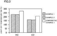
- T50 (°C) is a catalyst entrance gas temperature which is measured as follows: the temperature of model exhaust gas flowing into a catalyst is gradually increased from room temperature; changes in HC and CO concentrations of the gas flowing out of the catalyst are detected; and the temperature of exhaust gas at the entrance of the catalyst is measured when the removal ratio of each component reaches 50%.
- a model gas having a gas composition "10% of O 2 + 1800 ppm of CO + 50 ppm of NO + 50 ppm of NO 2 +100 ppm of NH 3 + 130 ppm of C-C 2 H 4 + 50 ppm of C-C 3 H 6 + 720 ppm of C-C 8 H 18 + 10% of H 2 O + N 2 (balance gas)" was caused to flow through the DPF and the AMOX at a gas flow rate of 40 L/min.
- An assessment temperature was increased from 100°C to 600°C at a temperature increase rate of 30°C/min to measure T50. The result is shown in FIG. 3 . Note that as described above, in all of Examples 1 and 2 and Comparative Example 1, the amount of Pt supported on the DPF+AMOX sample was 0.34 g/L with respect to the total volume of the DPF and the AMOX.
- the DPF+AMOX samples of Examples 1 and 2 employing the DPFs of Production Examples 1 and 2 have higher PM-burning performance than that of the DPF+AMOX sample of Comparative Example 1 employing the DPF of Production Example 3.
Landscapes
- Chemical & Material Sciences (AREA)
- Engineering & Computer Science (AREA)
- Chemical Kinetics & Catalysis (AREA)
- Combustion & Propulsion (AREA)
- Materials Engineering (AREA)
- Organic Chemistry (AREA)
- Mechanical Engineering (AREA)
- General Engineering & Computer Science (AREA)
- Health & Medical Sciences (AREA)
- Biomedical Technology (AREA)
- Environmental & Geological Engineering (AREA)
- Analytical Chemistry (AREA)
- General Chemical & Material Sciences (AREA)
- Oil, Petroleum & Natural Gas (AREA)
- Toxicology (AREA)
- Crystallography & Structural Chemistry (AREA)
- Physics & Mathematics (AREA)
- Geometry (AREA)
- Exhaust Gas After Treatment (AREA)
- Exhaust Gas Treatment By Means Of Catalyst (AREA)
- Catalysts (AREA)
- Processes For Solid Components From Exhaust (AREA)
Abstract
Description
- The present disclosure relates to exhaust gas purification systems.
- Diesel engines and lean-burn gasoline engines emit exhaust gases containing noxious substances such as hydrocarbons (HC), carbon monoxide (CO), NOx (nitrogen oxides), and particulates.
- As a system for processing such hazardous substances, for example, PATENT
DOCUMENT 1 describes a system in which exhaust gas is passed through an oxidation catalyst (DOC), catalyzed burning filter (CSF), reducing agent supply source, selective catalytic reduction (SCR) catalyst, and NH3 oxidation catalyst in that order. - According to
PATENT DOCUMENT 1, the CSF is a filter for capturing and burning off particulates contained in exhaust gas. The CSF includes Pt and Pd as noble metal components in order to improve particulate burning performance. In addition, Pt contained in the CSF can oxidize NO contained in exhaust gas to increase the NO2 concentration and thereby improve the NOx reduction purification performance of the SCR catalyst. - PATENT DOCUMENT 1: Japanese Patent No.
5937067 - Incidentally, the filter is operated at high temperature in order to burn off particulates, which causes the problem that the catalyst activity of Pt and Pd supported as catalytic noble metals is reduced due to sintering, etc.
- With the above in mind, the present disclosure has the problem of providing an exhaust gas purification system that can remove HC, CO, NOx, and particulates from exhaust gas, and has superior particulate burning performance and HC and CO removal performance.
- An exhaust gas purification system disclosed herein is disposed in an exhaust gas passage of an engine, and includes: a particulate filter configured to capture particulates contained in exhaust gas; an SCR catalyst provided downstream of the particulate filter in a direction of flow of the exhaust gas, and configured to reduce NOx contained in the exhaust gas for purification in the presence of a reducing agent; an injection unit provided between the particulate filter and the SCR catalyst, and configured to supply the reducing agent or a precursor of the reducing agent to the SCR catalyst so as to supply the reducing agent to the SCR catalyst; and a reducing agent oxidation catalyst provided downstream of the SCR catalyst in the direction of flow of the exhaust gas, and configured to remove the reducing agent having passed through the SCR catalyst. The particulate filter does not contain Pt or Pd and contains Rh. The reducing agent oxidation catalyst contains Pt.
- The temperature of the particulate filter is about 250°C during normal operation, and the peak temperature of the particulate filter increases to about 850°C during filter regeneration. Therefore, even in the case where Pt or Pd, which is a catalytic noble metal for accelerating burning of HC, CO, and particulates, is supported on the particulate filter, the catalytic performance may decrease due to sintering, etc.
- With this configuration, the particulate filter contains Rh, which has high particulate burning performance. Therefore, an exhaust gas purification system including a particulate filter having superior particulate burning performance can be provided although the particulate filter does not contain Pt or Pd. The temperature of the reducing agent oxidation catalyst provided downstream of the SCR catalyst is about 650°C even during filter regeneration. Therefore, by incorporating Pt into the reducing agent oxidation catalyst instead of the particulate filter, the reducing agent having passed through the SCR catalyst can be oxidized, and the decrease of catalytic performance due to sintering or the like of the catalytic noble metal can be reduced, and therefore, HC and CO contained in exhaust gas can be effectively removed.
- In a preferable embodiment, the amount of Pt contained in the reducing agent oxidation catalyst is 0.1-6.0 g/L with respect to the entire volume of the particulate filter and the reducing agent oxidation catalyst.
- With this configuration, by setting the amount of Pt contained in the reducing agent oxidation catalyst in the above range, HC and CO contained in exhaust gas can be effectively removed.
- In a preferable embodiment, the particulate filter contains a Zr-based composite oxide which does not contain Ce, and a Ce-containing Zr-based composite oxide doped with Rh.
- With this configuration, the particulate burning performance of the particulate filter can be improved.
- In a preferable embodiment, an oxidation catalyst is disposed upstream of the particulate filter in the direction of flow of the exhaust gas.
- With this configuration, the performance of removal of HC and CO contained in exhaust gas can be improved, and NO contained in exhaust gas is oxidized to NO2, and therefore, PM burning in the particulate filter is accelerated.
- As described above, according to the present disclosure, the particulate filter contains Rh, which has high particulate burning performance. Therefore, an exhaust gas purification system including a particulate filter having superior particulate burning performance can be provided although the particulate filter does not contain Pt or Pd. In addition, by incorporating Pt into the reducing agent oxidation catalyst instead of the particulate filter, the reducing agent having passed through the SCR catalyst can be oxidized, and the decrease of catalytic performance due to sintering or the like of the catalytic noble metal can be reduced, and therefore, HC and CO contained in exhaust gas can be effectively removed.
-
- [
FIG. 1] FIG. 1 is a diagram showing a configuration of an exhaust gas purifier for an engine. - [
FIG. 2] FIG. 2 is a graph diagram showing a carbon burning rate of each of DPFs of production examples. - [
FIG. 3] FIG. 3 is a graph diagram showing a light-off temperature (T50) of examples and a comparative example. - Embodiments of the present disclosure will now be described in detail with reference to the accompanying drawings. The preferred embodiments below are merely illustrative, and are in no way intended to limit the present disclosure, application, or uses.
-
FIG. 1 shows an exhaust gas purifier 1 (exhaust gas purification system) that can process HC, CO, NOx, and particulate matter (hereinafter referred to as "PM") contained in exhaust gas emitted from a lean-burn engine (engine) (not shown). The engine of this example is a diesel engine. In an exhaust gas passage W for the engine, as the exhaust gas purifier 1, an oxidation catalyst (DOC) 2, a diesel particulate filter (DPF) 3 with a catalyst as a particulate filter, a reducing agent or reducing agent precursor injection unit 4, amixer 5, anSCR catalyst 6, and a NH3 oxidation catalyst (AMOX) 7 as a reducing agent oxidation catalyst are disposed in this order with theoxidation catalyst 2 located most upstream in the direction of flow of exhaust gas. As used herein, the terms "upstream" and "downstream" refer to the direction of flow of exhaust gas. Theexhaust gas purifier 1 includes a tank for storing a reducing agent or reducing agent precursor, and various sensors. Based on signals from these sensors, the fuel injection control of the engine and the control of the injection unit 4 are carried out by an engine control unit (ECU). - The
DOC 2 contains an HC-trapping material for trapping HC contained in exhaust gas, and a catalytic component for oxidizing HC trapped by the HC-trapping material, and HC, CO, and NO contained in exhaust gas. For example, the HC-trapping material is preferably zeolite, and the oxidation catalytic component is preferably a catalyst in which Pt and/or Pd are supported on a mixture of active alumina and an oxygen storage capacity (OSC) material. The OSC material may be, for example, a Ce-containing oxide whose heat resistance is improved by a transition metal, such as Zr, or a rare-earth metal, such as Nd. - The
DOC 2, which contains the HC-trapping material, can trap HC in exhaust gas when the temperature of exhaust gas is low (catalyst is inactive), and can oxidize HC which is released from the HC-trapping material when the temperature of exhaust gas is high (catalyst is active) for purification, and therefore, can reduce the amount of HC that is emitted without being oxidized. - The
DPF 3 is for capturing and removing PM contained in exhaust gas. In theDPF 3, a PM-burning catalyst for accelerating PM burning is supported on the body of the filter for capturing PM. The PM burning is performed during regeneration of the filter in order to burn off captured PM. The filter body is of the wall-flow type, i.e., has a honeycomb structure in which an exhaust gas inflow passage having a closed downstream end and an exhaust gas outflow passage having a closed upstream end are alternately arranged in parallel, and exhaust gas flowing into an exhaust gas inflow passage flows out through pores of a passage separation wall into an adjacent exhaust gas outflow passage. The filter body is formed of an inorganic porous material, such as cordierite, SiC, Si3N4, SiAlON, or AlTiO3. - The PM-burning catalyst is preferably a mixture of a Zr-based composite oxide and a Rh-doped Ce-containing Zr-based composite oxide (Rh is located at crystal lattice points or between lattice points of the Ce-containing Zr-based composite oxide), and does not contain a catalytic noble metal having an oxidation catalytic function, such as Pt or Pd.
- The Zr-based composite oxide contains Zr as a main component, does not contain Ce, and contains rare-earth metals other than Ce, e.g., Y, Nd, Pr, La, and Yb, preferably Y, Nd, and Pr, and particularly preferably Y or Nd, and Pr.
- The Zr-based composite oxide can undergo an oxygen ion exchange reaction, and releases active oxygen without a change in valence of a metal ion. Because active oxygen is highly reactive, PM burning is accelerated without the presence of a catalytic noble metal, such as Pt or Pd. The contained amount of the Zr-based composite oxide is preferably 10-60 g per liter of the filter.
- The Ce-containing Zr-based composite oxide contains Zr as a main component, contains Ce, and preferably further contains rare-earth metals other than Ce, e.g., Y, Nd, Pr, La, and Yb, more preferably Y, Nd, Pr, and La, and particularly preferably Nd.
- The Ce-containing Zr-based composite oxide is an oxygen storage and release material, and has superior oxygen storage and release capacity based on a reversible reaction involving a change in valence of Ce. If such a Ce-containing Zr-based composite oxide is doped with Rh, the resultant composite oxide can accelerate a PM-burning reaction in which contact decreases in the course of burning.
- The amount of Rh contained in the Rh-doped Ce-containing Zr-based composite oxide is preferably 0.01-1 mass%, more preferably 0.05-0.5 mass%, for improving PM-burning performance.
- The mass ratio (the Zr-based composite oxide/the Rh-doped Ce-containing Zr-based composite oxide) of the Zr-based composite oxide and the Rh-doped Ce-containing Zr-based composite oxide is preferably 6/1-1/6, more preferably 4/1-1/4, for providing superior PM-burning performance.
- The
DOC 2, which is disposed upstream of theDPF 3, causes NO and oxygen (O2) contained in exhaust gas to react with each other to generate NO2. This NO2 is supplied together with oxygen (O2) contained in exhaust gas, as an oxidizing agent, to theDPF 3. Therefore, the burning of PM is accelerated. PM is reacted with oxygen or NO2 and thereby converted into CO2, which is emitted. - The injection unit 4, which is provided between the
DPF 3 and theSCR catalyst 6, supplies a reducing agent or a reducing agent precursor to theSCR catalyst 6. Specifically, the injection unit 4 may be an injection valve that supplies a reducing agent or reducing agent precursor stored in the tank into the exhaust gas passage W between theDPF 3 and themixer 5. Themixer 5 diffuses a reducing agent or a reducing agent precursor into exhaust gas contained in the exhaust gas passage W. - The
SCR catalyst 6 purifies exhaust gas by reducing NOx contained in the exhaust gas in the presence of a reducing agent. TheSCR catalyst 6 may be a commonly used SCR catalyst. Note that in this example, theSCR catalyst 6 is a urea-SCR employing urea as a precursor of a NH3, which serves as a reducing agent. Therefore, the tank stores urea water. TheSCR catalyst 6 may be a catalytic component in which a catalytic metal for reducing NOx using NH3 as a reducing agent is supported on zeolite for trapping NH3. The catalytic metal for reducing NOx may be preferably Fe, Cu, Ti, V, W, or the like. The use of Pt or Pd, which easily oxidize NH3 to NOx, is not preferable. - The injection unit 4 injects urea water into the exhaust gas passage W, and the urea is subjected to pyrolysis and hydrolysis to generate NH3 (reducing agent), which is adsorbed by the zeolite of the
SCR catalyst 6. NOx (NO and NO2) flowing into theSCR catalyst 6 is reduced to N2 by NH3 adsorbed by the zeolite or NH3 flowing into theSCR catalyst 6 for purification, and the N2 is emitted together with H2O generated during the reduction. - The
AMOX 7 traps and oxidizes (for purification) NH3 and a derivative thereof that has passed (slipped) through the SCR catalyst without reacting with NOx. TheAMOX 7 is preferably configured so that a Pt-supporting zeolite in which Pt is supported on zeolite for trapping NH3, and an OSC material, are supported on the cell wall of a honeycomb support. Note that Pt can accelerate oxidation of not only NH3 but also HC and CO contained in exhaust gas, and thereby purify the exhaust gas. The OSC material contained in theAMOX 7 may be, for example, a Ce-containing oxide whose heat resistance is improved by a transition metal, such as Zr, or a rare-earth metal, such as Nd. - Here, the amount of Pt contained in the
AMOX 7 is preferably 0.1-6.0 g/L, more preferably 0.2-1.0 g/L, with respect to the total volume of theDPF 3 and theAMOX 7 in order to effectively remove NH3, and HC and CO contained in exhaust gas. - NH3 and a derivative thereof that have passed through the SCR catalyst without reacting with NOx are trapped by the zeolite of the
AMOX 7. Therefore, NH3 and a derivative thereof are prevented from being emitted into the atmosphere. The NH3 and a derivative thereof that are trapped by the zeolite are released when the temperature of the zeolite is high, and are oxidized by the Pt catalyst before being emitted out. - Note that during regeneration of the
DPF 3, the temperature of theDPF 3 reaches about 850°C while the temperature of theAMOX 7 reaches about 650°C. Therefore, if Pt is supported on theAMOX 7 instead of Pt or Pd being supported on theDPF 3, the sintering of the catalytic noble metal can be prevented or reduced, so that the decrease of catalytic performance can be prevented, and therefore HC and CO contained in exhaust gas can be effectively removed. - As described above, the
exhaust gas purifier 1 of this embodiment, which includes theDPF 3, the injection unit 4, theSCR catalyst 6, and theAMOX 7, can remove HC, CO, NOx and PM from exhaust gas. In theexhaust gas purifier 1 of this embodiment, theDPF 3 contains Rh, which has high PM-burning performance, and therefore, has superior PM-burning performance without containing Pt or Pd. In addition, Pt is contained in theAMOX 7 instead of theDPF 3, and particularly, the contained amount of Pt is in the above range. Therefore, the oxidation of a reducing agent passing through theSCR catalyst 6 can be accelerated, and the decrease of catalytic performance due to sintering of the catalytic noble metal can be prevented or reduced, and therefore, theexhaust gas purifier 1 can have superior HC and CO removal performance. - Other embodiments of the present disclosure will now be described. In the description of these embodiments, the same parts as those of the first embodiment are denoted by the same reference characters and will not be described in detail.
- In the first embodiment, the
DOC 2 is provided upstream of theDPF 3. Alternatively, theDOC 2 may not be provided for some kinds of engines, for example. Note that it is desirable to provide theDOC 2 in order to improve the particulate burning performance of theDPF 3. - Alternatively, a NOx storage catalytic material (NSC) may be disposed instead of the
DOC 2. Furthermore, a composite catalyst (NSC+DOC) of theDOC 2 and NSC may be disposed. A configuration in which NSC+DOC is disposed will now be described. - NSC+DOC may be disposed by, for example, the following technique: the
DOC 2 described in the first embodiment is coated with a catalytic material which is a composite catalyst containing an NSC catalyst for temporarily trapping and reducing NOx in exhaust gas for purification and an oxidation catalyst (DOC) for oxidizing HC, CO, and NO in exhaust gas for purification. - The NSC catalyst contains: a catalytic component for oxidizing NO in exhaust gas; a NOx-trapping material for trapping NOx contained in exhaust gas when the air-fuel ratio of the exhaust gas is lean, and releasing NOx when the air-fuel ratio of the exhaust gas is in the range from the theoretical to rich air-fuel ratios; and a catalytic component for reducing NOx trapped in the NOx-trapping material. For example, the NO oxidation catalytic component is preferably a catalyst in which Pt is supported on a mixture of active alumina and a Ce-containing oxide as an OSC material, the NOx-trapping material is preferably a compound of an alkaline-earth metal, such as Ba, and the NOx-reducing catalytic component is preferably a catalyst in which Rh is contained in a mixture of active alumina and an OSC material (Ce-containing oxide).
- An alkaline-earth metal salt of acetic acid is employed as a raw material for the NOx-trapping material, is supported on a support, and is fired, resulting in an alkaline-earth metal salt of carbonic acid. Thus, this alkaline-earth metal salt of carbonic acid is the NOx-trapping material.
- The oxidation catalyst (DOC) may be one that is employed as the
DOC 2 of the first embodiment. - NSC+DOC can impart a NOx removal function to an upstream portion of a post-processing system in which exhaust gas has a relatively high temperature. The NOx removal function, together with HC oxidation by DOC for purification, can reduce the amount of NOx emitted, particularly during start (cold start) of an engine.
- The engine described in the above embodiments is a diesel engine. The present discloser is applicable to any lean-burn engines, including lean-burn gasoline engines, etc.
- Next, examples which were specifically carried out will be described.
- DPFs of Production Examples 1-3 shown in Table 1 were prepared.
Table 1 DPF Configuration Mass ratio Amount of supported Pt (g/L) Production Example 1 ZrYPrO ZrO2:Y2O3:Pr2O3 = 70:8:22 (mol%) 3 - Rh-doped CeZrNdO CeO2:ZrO2:Nd2O3 = 23:69:8 (mol%) Doped amount of Rh: 0.1 mass% 2 Production Example 2 ZrNdProO ZrO2:Nd2O3:Pr2O3 = 70:12:18 (mol%) 3 - Rh-doped CeZrNdO CeO2:ZrO2:Nd2O3 = 23:69:8 (mol%) Doped amount of Rh: 0.1 mass% 2 Production Example 3 ZrYPrO ZrO2:Y2O3:Pr2O3 = 70:8:22 (mol%) 3 0.08 Rh-doped CeZrNdO CeO2:ZrO2:Nd2O3 = 23:69:8 (mol%) Doped amount of Rh: 0.1 mass% 2 La-containing alumina La2O3:Al2O3 = 4:96 (mass%) 1 0.17 Pure alumina Al2O3 1 - In Production Examples 1-3, a ZrNdPr composite oxide (ZrNdPrO) and ZrYPr composite oxide (ZrYPrO) as the Zr-based composite oxide, and a Rh-doped CeZrNd composite oxide (Rh-doped CeZrNdO) as the Rh-doped Ce-containing Zr-based composite oxide, were prepared by the following preparation techniques. As the La-containing alumina and pure alumina in Production Example 3, respective commercially available powders were used.
- Praseodymium nitrate hexahydrate, zirconyl oxynitrate solution, and yttrium nitrate or neodymium nitrate hexahydrate were dissolved in ion-exchanged water. The resultant nitrate solution was mixed and neutralized with an 8-fold dilution of 28-mass% ammonia water to obtain a coprecipitate. A dehydration operation of putting the solution containing the coprecipitate into a centrifuge and removing supernatant, and a water-washing operation of adding ion-exchanged water and stirring, were alternately repeated a required number of times. The coprecipitate after final dehydration was dried in the atmosphere at 150°C for 24 hours, and thereafter, was pulverized using a ball mill. Thereafter, the pulverized coprecipitate was fired in the atmosphere at 500°C for 2 hours to obtain ZrYPrO or ZrNdPrO.
- Cerium nitrate hexahydrate, zirconyl oxynitrate solution, neodymium nitrate hexahydrate, and rhodium nitrate solution were dissolved in ion-exchanged water. The resultant nitrate solution was mixed and neutralized with an 8-fold dilution of 28-mass% ammonia water to obtain a coprecipitate. A dehydration operation of putting the solution containing the coprecipitate into a centrifuge and removing supernatant, and a water-washing operation of adding ion-exchanged water and stirring, were alternately repeated a required number of times. The coprecipitate after final dehydration was dried in the atmosphere at 150°C for 24 hours, and thereafter, was pulverized using a ball mill. Thereafter, the pulverized coprecipitate was fired in the atmosphere at 500°C for 2 hours to obtain Rh-doped CeZrNdO.
- Both of the DPFs included, as the filter body, a honeycomb-shaped filter of SiC (capacity: 25 mL, cell wall thickness: 16 mil, and number of cells: 178 cpsi).
- ZrYPrO or ZrNdPrO, and Rh-doped CeZrNdO, were mixed together, and zirconia binder solution and ion-exchanged water were added to the mixed powder, following mixing, to obtain a slurry. The slurry was pulverized using a ball mill to a number-average particle size of about 200-400 nm (preferably about 300 nm). The filter body was coated with the resultant slurry. The slurry was dried in the atmosphere at 150°C, and was fired in the atmosphere at 500°C for 2 hours, to obtain the DPF of Production Example 1 or 2.
- ZrYPrO and Rh-doped CeZrNdO were mixed together, and ion-exchanged water was added to the resultant mixture to obtain a slurry, and the slurry was thoroughly stirred using a stirrer or the like. While continuing to stir the slurry, a predetermined amount of ethanolamine Pt (hexahydroxoplatinum(IV) acid ethanolamine solution) was dropped into the slurry, and the resultant mixture was thoroughly stirred. Thereafter, stirring was further continued while heating, so that water was completely evaporated. After the evaporation, the resultant dry solid was pulverized, and fired in the atmosphere at 500°C for 2 hours. As a result, a catalyst powder was obtained in which Pt is supported on ZrYPrO and Rh-doped CeZrNdO.
- The active alumina catalyst powder of Production Example 3 was prepared as follows. Specifically, a plurality of kinds of active alumina (pure alumina and La-containing alumina) were mixed together, and ion-exchanged water was added to the mixture to obtain a slurry, and the slurry was thoroughly stirred using a stirrer or the like. Next, while stirring the slurry, a predetermined amount of ethanolamine Pt was dropped into the slurry, and the resultant mixture was thoroughly stirred. Thereafter, stirring was further continued while heating, so that water was completely evaporated. After the evaporation, the resultant dry solid was pulverized, and fired in the atmosphere at 500°C for 2 hours. As a result, a catalyst powder was obtained in which Pt is supported on each type of alumina.
- A catalyst powder in which Pt is supported on the above active alumina (pure alumina and La-containing alumina), and a catalyst powder in which Pt is supported on the above ZrYPrO and Rh-doped CeZrNdO, were mixed together, and zirconia binder solution and ion-exchanged water were added to the resultant mixed powder, followed by mixing, to obtain a slurry. The filter body was coated with the slurry, was dried in the atmosphere at 150°C, and thereafter, was fired in the atmosphere at 500°C for 2 hours, to obtain the DPF of Production Example 3.
- Each of the DPFs of Production Examples 1-3 was stored, i.e., aged, in the atmosphere at a temperature of 800°C for 24 hours. Thereafter, soot was deposited on each DPF by a procedure below, and the PM-burning performance of each DPF was investigated.
- Initially, 5 g/L of carbon black was added to ion-exchanged water, and the mixture was stirred using a stirrer, so that the carbon black was thoroughly dispersed. An entrance end of the aged DPF was immersed in the resultant slurry, and the slurry was suctioned from an exit end of the DPF using an aspirator. Water that was not removed by the suction was removed by air blowing through an end surface of the filter which was immersed in the slurry. Thereafter, the DPF was held and dried at a
temperature 150°C for 2 hours. - Each DPF on which soot was thus deposited was attached to a fixed-floor model gas flow device. The temperature of N2 gas at the entrance of the DPF was increased from room temperature to 580°C while the N2 gas was caused to flow through the DPF. After the temperature became stable at 580°C, the composition of the gas was changed to "7.5% of O2 + 300 ppm of NO + N2 (balance gas)" with the temperature maintained, and that gas was caused to flow through the DPF at a gas flow rate of 40 L/min. The concentrations of CO and CO2 that were generated by burning carbon, in the gas, were measured at the exit of the filter in real time. The rate at which carbon was burnt (the amount of carbon burnet per unit time) was measured from these concentrations, every predetermined period of time, using the following calculation expression (1).

- The cumulative value of the amount of carbon burnt over time was also calculated. The rate at which soot was burnt (the amount of soot burnt per minute in one liter of the filter (g/min-L)) was calculated from the time it took for the soot burning ratio to reach 90%. The result is shown in
FIG. 2 . - It was found that the DPFs of Production Examples 1 and 2 prepared using a catalyst powder on which Pt or Pd is not supported had a high soot burning rate and superior PM-burning performance, compared to the DPF of Production Example 3 prepared using a catalyst powder on which Pt is supported.
- DPF+AMOX samples of Examples 1 and 2 and Comparative Example 1 shown in Table 2 were prepared. Note that for the sake of simplicity, DOC and SCR catalysts were not provided.
Table 2 DPF [Catalyst volume: 25 mL] AMOX [Catalyst volume: 13 mL] Production Example Amount of catalyst (g/L) Amount of supported Pt (g/L) Amount of supported Pt (g/L) Example 1 1 28 - 1.0 Example 2 2 28 - 1.0 Comparative Example 1 3 28 0.25 0.50 - As the catalyst support of an AMOX, a flow-through honeycomb support of cordierite (capacity: 13 mL, cell wall thickness: 4.5 mil, and number of cells: 400 cpsi) was used.
- An AMOX was obtained by supporting, on the above honeycomb support, zeolite on which Pt is supported, and a CeZrNd composite oxide (CeZrNdO) as an OSC material, using a procedure described below.
- Ion-exchanged water was added to a commercially available zeolite powder to obtain a slurry, and the slurry was thoroughly stirred using a stirrer or the like. Next, while stirring the slurry, a predetermined amount of ethanolamine Pt was dropped into the slurry, and the resultant mixture was thoroughly stirred. Thereafter, stirring was further continued while heating, so that water was completely evaporated. After the evaporation, the resultant dry solid was pulverized, and fired in the atmosphere at 500°C for 2 hours. As a result, a Pt-supported catalyst powder was obtained.
- Cerium nitrate hexahydrate, zirconyl oxynitrate solution, and neodymium nitrate hexahydrate were dissolved in ion-exchanged water. The resultant nitrate solution was mixed and neutralized with an 8-fold dilution of 28-mass% ammonia water to obtain a coprecipitate. A dehydration operation of putting the solution containing the coprecipitate into a centrifuge and removing supernatant, and a water-washing operation of adding ion-exchanged water and stirring, were alternately repeated a required number of times. The coprecipitate after final dehydration was dried in the atmosphere at 150°C for 24 hours, and thereafter, was pulverized using a ball mill. Thereafter, the pulverized coprecipitate was fired in the atmosphere at 500°C for 2 hours to obtain CeZrNdO.
- The Pt-supporting zeolite powder and the CeZrNdO were mixed together, and zirconia binder solution and ion-exchanged water were added to the resultant mixed powder, followed by mixing, to obtain a slurry. The filter body was coated with the slurry, was dried in the atmosphere at 150°C, and thereafter, was fired in the atmosphere at 500°C for 2 hours, to obtain an AMOX. Note that the amount of Pt supported on the AMOX was 1.0 g/L in Examples 1 and 2, and 0.50 g/L in Comparative Example 1. The amount of supported Pt with respect to the entire volume of the DPF and the AMOX was 0.34 g/L in all of Examples 1 and 2 and Comparative Example 1.
- The DPFs of Production Examples 1-3 were subjected to a thermal treatment at 800°C for 24 hours in a thermal-treatment-in-the-atmosphere furnace, as an aging treatment. The AMOX was subjected to a thermal treatment at 650°C for 45 hours (2% O2, 10% H2O, balance N2) in a thermal-treatment-in-ambient-gas furnace, as an aging treatment.
- Thereafter, the DPF and the AMOX of any of Production Examples 1-3 shown in Table 2 were attached to a gas flow reaction device in this order with the DPF located upstream of the AMOX, and each light-off temperature T50 (°C) involved with removal of HC and CO was measured. T50 (°C) is a catalyst entrance gas temperature which is measured as follows: the temperature of model exhaust gas flowing into a catalyst is gradually increased from room temperature; changes in HC and CO concentrations of the gas flowing out of the catalyst are detected; and the temperature of exhaust gas at the entrance of the catalyst is measured when the removal ratio of each component reaches 50%.
- A model gas having a gas composition "10% of O2 + 1800 ppm of CO + 50 ppm of NO + 50 ppm of NO2 +100 ppm of NH3 + 130 ppm of C-C2H4 + 50 ppm of C-C3H6 + 720 ppm of C-C8H18 + 10% of H2O + N2 (balance gas)" was caused to flow through the DPF and the AMOX at a gas flow rate of 40 L/min. An assessment temperature was increased from 100°C to 600°C at a temperature increase rate of 30°C/min to measure T50. The result is shown in
FIG. 3 . Note that as described above, in all of Examples 1 and 2 and Comparative Example 1, the amount of Pt supported on the DPF+AMOX sample was 0.34 g/L with respect to the total volume of the DPF and the AMOX. - It was found that the DPF+AMOX samples of Examples 1 and 2 in which Pt is supported only on the AMOX have a lower T50 with respect to both of HC and CO, and have higher HC and CO removal performance, than those of the DPF+AMOX sample of Comparative Example 1 in which Pt is supported on both of the DPF and the AMOX.
- According to the result of
FIG. 2 , the DPF+AMOX samples of Examples 1 and 2 employing the DPFs of Production Examples 1 and 2 have higher PM-burning performance than that of the DPF+AMOX sample of Comparative Example 1 employing the DPF of Production Example 3. - Thus, it was found that the DPF+AMOX samples of Examples 1 and 2 have more excellent PM-burning performance and HC and CO removal performance than those of the DPF+AMOX sample of Comparative Example 1.
-
- 1 EXHAUST GAS PURIFIER (EXHAUST GAS PURIFICATION SYSTEM)
- 2 OXIDATION CATALYST, DOC
- 3 DIESEL PARTICULATE FILTER WITH CATALYST, DPF (PARTICULATE FILTER)
- 4 INJECTION UNIT
- 5 MIXER
- 6 SCR CATALYST
- 7 NH3 OXIDATION CATALYST, AMOX (REDUCING AGENT OXIDATION CATALYST)
- W EXHAUST GAS PASSAGE
Claims (4)
- An exhaust gas purification system disposed in an exhaust gas passage of an engine, comprising:a particulate filter configured to capture particulates contained in exhaust gas;an SCR catalyst provided downstream of the particulate filter in a direction of flow of the exhaust gas, and configured to reduce NOx contained in the exhaust gas for purification in the presence of a reducing agent;an injection unit provided between the particulate filter and the SCR catalyst, and configured to supply the reducing agent or a precursor of the reducing agent to the SCR catalyst so as to supply the reducing agent to the SCR catalyst; anda reducing agent oxidation catalyst provided downstream of the SCR catalyst in the direction of flow of the exhaust gas, and configured to remove the reducing agent having passed through the SCR catalyst,
whereinthe particulate filter does not contain Pt or Pd and contains Rh, andthe reducing agent oxidation catalyst contains Pt. - The exhaust gas purification system of claim 1,
wherein
the amount of Pt contained in the reducing agent oxidation catalyst is 0.1-6.0 g/L with respect to the entire volume of the particulate filter and the reducing agent oxidation catalyst. - The exhaust gas purification system of claim 1 or 2,
wherein
the particulate filter contains a Zr-based composite oxide which does not contain Ce, and a Ce-containing Zr-based composite oxide doped with Rh. - The exhaust gas purification system of any one of claims 1-3,
wherein
an oxidation catalyst is disposed upstream of the particulate filter in the direction of flow of the exhaust gas.
Applications Claiming Priority (2)
| Application Number | Priority Date | Filing Date | Title |
|---|---|---|---|
| JP2017123666A JP6443501B1 (en) | 2017-06-23 | 2017-06-23 | Exhaust gas purification system |
| PCT/JP2018/023029 WO2018235752A1 (en) | 2017-06-23 | 2018-06-15 | Exhaust gas purification system |
Publications (2)
| Publication Number | Publication Date |
|---|---|
| EP3636890A1 true EP3636890A1 (en) | 2020-04-15 |
| EP3636890A4 EP3636890A4 (en) | 2020-04-15 |
Family
ID=64735623
Family Applications (1)
| Application Number | Title | Priority Date | Filing Date |
|---|---|---|---|
| EP18820710.4A Withdrawn EP3636890A4 (en) | 2017-06-23 | 2018-06-15 | EXHAUST GAS PURIFICATION SYSTEM |
Country Status (5)
| Country | Link |
|---|---|
| US (1) | US10989082B2 (en) |
| EP (1) | EP3636890A4 (en) |
| JP (1) | JP6443501B1 (en) |
| CN (1) | CN110785546A (en) |
| WO (1) | WO2018235752A1 (en) |
Cited By (1)
| Publication number | Priority date | Publication date | Assignee | Title |
|---|---|---|---|---|
| DE102020207311A1 (en) | 2020-06-11 | 2021-12-16 | Volkswagen Aktiengesellschaft | Ammonia barrier catalyst, exhaust aftertreatment system and process for exhaust aftertreatment |
Families Citing this family (5)
| Publication number | Priority date | Publication date | Assignee | Title |
|---|---|---|---|---|
| FR3103117A1 (en) * | 2019-11-20 | 2021-05-21 | Psa Automobiles Sa | Process for treating NOx with ammonia produced in-situ in a motor vehicle particulate filter and device for implementing the process |
| KR102335497B1 (en) * | 2020-09-22 | 2021-12-08 | 한국전력공사 | Exhaust gas purification device for diesel engine and passive regeneration method thereof |
| JP7498430B2 (en) | 2020-10-14 | 2024-06-12 | スズキ株式会社 | Exhaust gas purification equipment |
| EP4015065B1 (en) * | 2020-12-15 | 2025-02-26 | Umicore AG & Co. KG | Catalytically active particle filter with high filtration efficiency |
| EP4206445B1 (en) * | 2022-01-04 | 2024-06-26 | Volvo Truck Corporation | An exhaust aftertreatment system |
Family Cites Families (21)
| Publication number | Priority date | Publication date | Assignee | Title |
|---|---|---|---|---|
| JPS5937067B2 (en) | 1982-02-09 | 1984-09-07 | 愛媛県青果農業協同組合連合会 | Method for producing fruit drink with cheese |
| JP2005329318A (en) * | 2004-05-19 | 2005-12-02 | Mazda Motor Corp | Diesel particulate filter |
| WO2006044268A1 (en) * | 2004-10-13 | 2006-04-27 | Dow Global Technologies Inc. | Catalysed diesel soot filter and process for its use |
| JP2006289211A (en) * | 2005-04-07 | 2006-10-26 | Ne Chemcat Corp | Ammonia oxidation catalyst |
| JP5326251B2 (en) * | 2007-10-02 | 2013-10-30 | マツダ株式会社 | Exhaust gas purification catalyst device |
| EP2392791A1 (en) * | 2009-01-30 | 2011-12-07 | Toyota Jidosha Kabushiki Kaisha | Exhaust purifying device |
| CN102822460B (en) * | 2010-03-26 | 2015-04-29 | 株式会社科特拉 | Exhaust gas purification system |
| JP2012154259A (en) * | 2011-01-26 | 2012-08-16 | Mazda Motor Corp | Exhaust gas purification catalytic system |
| CN103582523B (en) | 2011-04-28 | 2015-11-25 | 恩亿凯嘉股份有限公司 | Waste gas purification apparatus |
| JP5742625B2 (en) * | 2011-09-22 | 2015-07-01 | マツダ株式会社 | Particulate filter with catalyst |
| JP5834925B2 (en) * | 2012-01-11 | 2015-12-24 | マツダ株式会社 | Particulate filter with catalyst |
| JP5982987B2 (en) * | 2012-04-23 | 2016-08-31 | マツダ株式会社 | Exhaust gas purification catalyst containing exhaust gas purification catalyst material |
| JP5991162B2 (en) * | 2012-11-20 | 2016-09-14 | マツダ株式会社 | Particulate filter with catalyst |
| JP5942894B2 (en) * | 2013-02-21 | 2016-06-29 | マツダ株式会社 | Method for producing exhaust gas purifying catalyst |
| JP5942893B2 (en) * | 2013-02-21 | 2016-06-29 | マツダ株式会社 | Method for producing exhaust gas purifying catalyst |
| DE112014000481T5 (en) * | 2013-05-27 | 2015-11-05 | Mazda Motor Corporation | Exhaust gas purifying catalyst and manufacturing method therefor |
| JP6197994B2 (en) * | 2013-07-29 | 2017-09-20 | 三菱自動車工業株式会社 | Exhaust gas purification device for internal combustion engine |
| DE112014005291T5 (en) * | 2013-11-20 | 2016-08-04 | Mazda Motor Corporation | Catalyst material for exhaust gas purification and method for producing the same |
| WO2016031104A1 (en) * | 2014-08-29 | 2016-03-03 | マツダ株式会社 | Exhaust gas purifying catalyst device and exhaust gas purifying method |
| JP2016079912A (en) * | 2014-10-17 | 2016-05-16 | マツダ株式会社 | Exhaust emission control system and emission control method |
| JP6202021B2 (en) * | 2015-02-26 | 2017-09-27 | マツダ株式会社 | Particulate filter with catalyst |
-
2017
- 2017-06-23 JP JP2017123666A patent/JP6443501B1/en not_active Expired - Fee Related
-
2018
- 2018-06-15 CN CN201880041856.XA patent/CN110785546A/en active Pending
- 2018-06-15 EP EP18820710.4A patent/EP3636890A4/en not_active Withdrawn
- 2018-06-15 WO PCT/JP2018/023029 patent/WO2018235752A1/en not_active Ceased
- 2018-06-15 US US16/625,472 patent/US10989082B2/en not_active Expired - Fee Related
Cited By (2)
| Publication number | Priority date | Publication date | Assignee | Title |
|---|---|---|---|---|
| DE102020207311A1 (en) | 2020-06-11 | 2021-12-16 | Volkswagen Aktiengesellschaft | Ammonia barrier catalyst, exhaust aftertreatment system and process for exhaust aftertreatment |
| DE102020207311B4 (en) | 2020-06-11 | 2022-09-08 | Volkswagen Aktiengesellschaft | Ammonia slip catalyst, exhaust aftertreatment system and exhaust aftertreatment method |
Also Published As
| Publication number | Publication date |
|---|---|
| CN110785546A (en) | 2020-02-11 |
| JP2019007418A (en) | 2019-01-17 |
| EP3636890A4 (en) | 2020-04-15 |
| US10989082B2 (en) | 2021-04-27 |
| JP6443501B1 (en) | 2018-12-26 |
| US20200392881A1 (en) | 2020-12-17 |
| WO2018235752A1 (en) | 2018-12-27 |
Similar Documents
| Publication | Publication Date | Title |
|---|---|---|
| US10989082B2 (en) | Exhaust gas purification system | |
| EP1967263B1 (en) | Catalytic Material And Catalyst For Purifying Exhaust Gas Component | |
| US8409518B2 (en) | Sulfur tolerant perovskite supported catalysts | |
| JP5854995B2 (en) | Gasoline engine exhaust gas treatment system | |
| JP5717654B2 (en) | Filter for collecting particulate matter from exhaust gas discharged from a positive ignition engine | |
| US7871452B2 (en) | Particulate filter | |
| US8932546B2 (en) | Catalytically active particulate filter and use thereof | |
| KR101855537B1 (en) | Nox storage catalyst with reduced rh loading | |
| EP4058182A1 (en) | Particulate filter | |
| JP4985423B2 (en) | Exhaust gas component purification catalyst material and exhaust gas component purification catalyst | |
| US11305260B2 (en) | Catalyst for gasoline engine exhaust gas aftertreatment | |
| JP4985299B2 (en) | Exhaust gas component purification catalyst material and particulate filter with the catalyst material | |
| JP5023969B2 (en) | Exhaust gas component purification catalyst material and particulate filter with the catalyst material | |
| JP5954159B2 (en) | Particulate filter with catalyst | |
| JP5991162B2 (en) | Particulate filter with catalyst | |
| JP2009106855A (en) | Exhaust gas component purification catalyst material and particulate filter with the catalyst material | |
| JP4858394B2 (en) | Exhaust gas component purification catalyst material and particulate filter with the catalyst material | |
| JP2009090238A (en) | Exhaust gas component purification catalyst material and particulate filter with the catalyst material | |
| JP2018161618A (en) | Manufacturing method for particulate filter with catalyst | |
| JP5029273B2 (en) | Particulate filter | |
| JP5949520B2 (en) | Particulate filter with catalyst | |
| JP5979014B2 (en) | Manufacturing method of particulate filter with catalyst | |
| US9550171B2 (en) | Exhaust gas purification catalyst and method for manufacturing same | |
| JP6288113B2 (en) | Particulate filter |
Legal Events
| Date | Code | Title | Description |
|---|---|---|---|
| STAA | Information on the status of an ep patent application or granted ep patent |
Free format text: STATUS: THE INTERNATIONAL PUBLICATION HAS BEEN MADE |
|
| PUAI | Public reference made under article 153(3) epc to a published international application that has entered the european phase |
Free format text: ORIGINAL CODE: 0009012 |
|
| STAA | Information on the status of an ep patent application or granted ep patent |
Free format text: STATUS: REQUEST FOR EXAMINATION WAS MADE |
|
| 17P | Request for examination filed |
Effective date: 20200108 |
|
| A4 | Supplementary search report drawn up and despatched |
Effective date: 20200306 |
|
| AK | Designated contracting states |
Kind code of ref document: A1 Designated state(s): AL AT BE BG CH CY CZ DE DK EE ES FI FR GB GR HR HU IE IS IT LI LT LU LV MC MK MT NL NO PL PT RO RS SE SI SK SM TR |
|
| AX | Request for extension of the european patent |
Extension state: BA ME |
|
| DAV | Request for validation of the european patent (deleted) | ||
| DAX | Request for extension of the european patent (deleted) | ||
| STAA | Information on the status of an ep patent application or granted ep patent |
Free format text: STATUS: EXAMINATION IS IN PROGRESS |
|
| 17Q | First examination report despatched |
Effective date: 20201007 |
|
| RIC1 | Information provided on ipc code assigned before grant |
Ipc: F01N 3/035 20060101AFI20210325BHEP Ipc: B01J 23/56 20060101ALI20210325BHEP Ipc: B01J 23/00 20060101ALI20210325BHEP Ipc: B01J 21/06 20060101ALI20210325BHEP Ipc: B01J 23/42 20060101ALI20210325BHEP Ipc: B01J 23/46 20060101ALI20210325BHEP Ipc: F01N 13/00 20100101ALI20210325BHEP Ipc: F01N 3/20 20060101ALI20210325BHEP Ipc: F01N 3/10 20060101ALI20210325BHEP Ipc: F01N 3/08 20060101ALI20210325BHEP Ipc: B01J 29/068 20060101ALI20210325BHEP Ipc: B01J 23/63 20060101ALI20210325BHEP Ipc: B01D 53/94 20060101ALI20210325BHEP Ipc: B01J 35/04 20060101ALI20210325BHEP Ipc: B01J 37/02 20060101ALI20210325BHEP Ipc: B01J 37/04 20060101ALI20210325BHEP |
|
| GRAP | Despatch of communication of intention to grant a patent |
Free format text: ORIGINAL CODE: EPIDOSNIGR1 |
|
| STAA | Information on the status of an ep patent application or granted ep patent |
Free format text: STATUS: GRANT OF PATENT IS INTENDED |
|
| GRAJ | Information related to disapproval of communication of intention to grant by the applicant or resumption of examination proceedings by the epo deleted |
Free format text: ORIGINAL CODE: EPIDOSDIGR1 |
|
| GRAJ | Information related to disapproval of communication of intention to grant by the applicant or resumption of examination proceedings by the epo deleted |
Free format text: ORIGINAL CODE: EPIDOSDIGR1 |
|
| GRAP | Despatch of communication of intention to grant a patent |
Free format text: ORIGINAL CODE: EPIDOSNIGR1 |
|
| STAA | Information on the status of an ep patent application or granted ep patent |
Free format text: STATUS: EXAMINATION IS IN PROGRESS |
|
| GRAP | Despatch of communication of intention to grant a patent |
Free format text: ORIGINAL CODE: EPIDOSNIGR1 |
|
| STAA | Information on the status of an ep patent application or granted ep patent |
Free format text: STATUS: GRANT OF PATENT IS INTENDED |
|
| INTG | Intention to grant announced |
Effective date: 20210514 |
|
| INTG | Intention to grant announced |
Effective date: 20210514 |
|
| INTG | Intention to grant announced |
Effective date: 20210531 |
|
| STAA | Information on the status of an ep patent application or granted ep patent |
Free format text: STATUS: THE APPLICATION IS DEEMED TO BE WITHDRAWN |
|
| 18D | Application deemed to be withdrawn |
Effective date: 20211012 |