EP3636873B1 - Ensemble de connexion pour raccorder des tuyaux - Google Patents
Ensemble de connexion pour raccorder des tuyaux Download PDFInfo
- Publication number
- EP3636873B1 EP3636873B1 EP19181463.1A EP19181463A EP3636873B1 EP 3636873 B1 EP3636873 B1 EP 3636873B1 EP 19181463 A EP19181463 A EP 19181463A EP 3636873 B1 EP3636873 B1 EP 3636873B1
- Authority
- EP
- European Patent Office
- Prior art keywords
- pipes
- connection member
- threads
- internal
- tubular connection
- Prior art date
- Legal status (The legal status is an assumption and is not a legal conclusion. Google has not performed a legal analysis and makes no representation as to the accuracy of the status listed.)
- Active
Links
- 238000005553 drilling Methods 0.000 claims description 16
- 239000000463 material Substances 0.000 claims description 16
- 230000008878 coupling Effects 0.000 description 5
- 238000010168 coupling process Methods 0.000 description 5
- 238000005859 coupling reaction Methods 0.000 description 5
- 239000012530 fluid Substances 0.000 description 4
- 229910000831 Steel Inorganic materials 0.000 description 3
- 239000010959 steel Substances 0.000 description 3
- 238000003466 welding Methods 0.000 description 3
- 229910000861 Mg alloy Inorganic materials 0.000 description 2
- 238000005524 ceramic coating Methods 0.000 description 2
- 238000005336 cracking Methods 0.000 description 2
- 238000005304 joining Methods 0.000 description 2
- 238000004519 manufacturing process Methods 0.000 description 2
- 229910052751 metal Inorganic materials 0.000 description 2
- 239000002184 metal Substances 0.000 description 2
- 239000004576 sand Substances 0.000 description 2
- 239000004575 stone Substances 0.000 description 2
- 229910045601 alloy Inorganic materials 0.000 description 1
- 239000000956 alloy Substances 0.000 description 1
- 239000011248 coating agent Substances 0.000 description 1
- 238000000576 coating method Methods 0.000 description 1
- 230000006835 compression Effects 0.000 description 1
- 238000007906 compression Methods 0.000 description 1
- 238000010276 construction Methods 0.000 description 1
- 230000007423 decrease Effects 0.000 description 1
- 239000011499 joint compound Substances 0.000 description 1
- 239000003129 oil well Substances 0.000 description 1
- 238000002360 preparation method Methods 0.000 description 1
- 239000010935 stainless steel Substances 0.000 description 1
- 229910001220 stainless steel Inorganic materials 0.000 description 1
Images

Classifications
-
- E—FIXED CONSTRUCTIONS
- E21—EARTH OR ROCK DRILLING; MINING
- E21B—EARTH OR ROCK DRILLING; OBTAINING OIL, GAS, WATER, SOLUBLE OR MELTABLE MATERIALS OR A SLURRY OF MINERALS FROM WELLS
- E21B17/00—Drilling rods or pipes; Flexible drill strings; Kellies; Drill collars; Sucker rods; Cables; Casings; Tubings
- E21B17/02—Couplings; joints
- E21B17/04—Couplings; joints between rod or the like and bit or between rod and rod or the like
- E21B17/042—Threaded
Definitions
- the present invention relates to a connection assembly for connecting pipes, comprising two pipes having internal threads on an inner surface of the pipe arranged at an end portion of the pipe over a distance d, and a tubular connection member having external threads on an outer surface adapted to engage with the internal threads of the pipes.
- Drilling with steel pipes is done by using a sequence of long pipes that are drilled through sand and stone in the ground. 1 to 12-meter-long steel pipes may be used. These pipes can be increased in length by the addition of extra pipes, which are fastened on the first pipe. Fastening is done by screwing the second pipe, which has an external thread on an outside surface, on an internal thread positioned on an inside surface of a fastening portion positioned on an end portion of the first pipe.
- a problem with the fastening portion is that it bulges from the outer surface of the pipes. This causes the pipes to stick in the ground during drilling because sand, mud and stone rest on the bulges and prevent the pipes from moving upwards or downwards.
- a solution has been found by providing a pipe, wherein at the end of each pipe half the thickness of the wall of the pipe is used to provide a thread. One end of the pipe has these threads on the inside and one end of the pipe has these threads on the outside so that internal threads can be screwed on external threads.
- a disadvantage of this solution is that the thickness of the wall of the pipe is reduced by 50%. Such a reduction is too much to withstand the excessive stresses applied on the pipes during drilling. The tensile, circumferential and elastic stress causes the material at these types of connections to crack. Cracks can propagate to final rupture.
- Another solution is by welding the pipes together. This provides a direct contact between the endings of the pipes, whereby the tensile yield strength is not reduced by a thinner wall of a connection assembly.
- the problem is that welding is time consuming making welding an expensive alternative to use in practice.
- US3361448 discloses a drill rod assembly between two pipes with internal threads adapted to receive a coupling device of a magnesium alloy comprising external threads at two end portions.
- the coupling device comprises a centre portion with an outer diameter substantially corresponding to the outer diameter of the pipe.
- the two end portions have a smaller outer diameter than the centre portion allowing it to engage inside the bore of the pipes.
- Both ends of the centre portions comprise a shoulder adapted to bear against the end portions of the pipes.
- the centre part is subjected to high tensile yield stress caused by the compression of the end portions of the coupling device and by the endings of the pipes bearing directly on the centre part.
- the thinner wall at the connection point reduces the strength to withstand the stresses, such as circumferential stresses, at the connection point during drilling.
- This reduction in strength is partly compensated by using a material, such as a magnesium alloy for the coupling device.
- a material such as a magnesium alloy for the coupling device.
- a ceramic coating is used on the threads, which coating breaks into small pieced on a surface of the threads. Upon screwing and other pressures, these pieces form a stable coupling between the pipes.
- US4813717 discloses a connection for oilwell tubing.
- This connection comprises a centre portion and two connecting joints at end portions with tapered external threads.
- the centre part of the connection has the same outer diameter as the pipes. It is subjected to high tensile yield stresses and the thinner wall at the connection point reduces the strength as mentioned above.
- This loss in strength is mainly compensated for by the pipes having an internal tapered thread with a loadbearing flank angle of 75° or more.
- the angle of the threads can be dimensioned depending on the stresses that need to be managed by the connection.
- the length of the connection can be altered and the thickness of the inner wall of the connection may be increased.
- dimensioning the threads, altering length and thickness of walls is complex, expensive and time consuming.
- connection assembly for connecting pipes during drilling.
- the connection member has threads that do not extend parallel along the axis of the pipe, but rather have a curved shape. Also, the height of the threads decreases towards the ends of the connection member. Curved threads having different heights are complex and expensive to manufacture. Further, the ends of the connection member do not abut against the pipe wall but form a 90° edge, where materials can get stuck at the connection member when being put into or taken out of the pipes.
- connection must be easy and quick to apply during drilling as well strong enough to withstand the forces applied on it during drilling to prevent cracking of the metal.
- outer diameter at the connection point should be the same as the outer diameter of the pipes.
- connection assembly for connecting pipes during drilling comprising two pipes having internal threads on an inner surface of the pipe.
- the internal threads are arranged at an end portion of the pipe over a distance along the length of the pipe.
- the assembly also comprises a tubular connection member having external threads at an outer surface adapted to engage with the internal threads of the pipes.
- the tubular connection member has an outer diameter adapted to be inserted into bores of the pipes.
- the pipes are in contact with each other at the end portions of the pipes when the tubular connection member is arranged in the bores and both pipes are fully engaged in the tubular connection member.
- the tubular connection member has an end portions comprising an angled surface, whereby the angle of the angled surface in relation to longitudinal axis is more than 125°
- connection assembly An advantageous of the connection assembly is that the endings of the connecting pipes are in contact with each other. This causes the tensile yield strength to be split between the pipes and the connection member. Further, the thickness of the wall of the connection member plus the pipes is larger than the thickness of the walls of the pie. This improves withstanding circumferential stresses and tensile strength at the connection, in contrast to the prior art connection devices, where a loss of strength at the connection needs to be compensated by using dimensioned threads or ceramic coatings, etc. Also, no material needs to be removed as would have been needed if the connection member had an outer surface directly bearing on the outer surface of the pipes.
- Threads may be square or not. Threads may be radiused at a base of threads.
- the connection assembly provides a simple and cost-effective structure that can be constructed and used in a simple manner.
- the internal and external threads are turned in the same direction as the direction of rotation of a drill. Drilling conditions may be with a left or right rotation of the drill string. Right-handed threads are used if drilling is done in a right rotation. This prevents the pipes and connection member from unscrewing during drilling.
- the internal and external threads extend parallel along a longitudinal axis of the pipes.
- the internal and external threads all have the same length.
- the internal and external threads all have the same shape and form. This provides for a simple and cost-effective construction since no tapering or dimensioning of threads is needed.
- the threads are not tapered.
- a shoulder at the distance indicates an end of the internal threads of the pipe.
- a shoulder at the end of the threads on the internal surface of the pipes provides for a stop.
- the tubular connection member cannot be screwed further into the pipes than the shoulder. This prevents screwing the tubular connection member deeper than necessary into the pipe.
- the tubular connection member can neither become disconnected during drilling.
- the ratio of an inner diameter of the pipe to a length of the tubular connection member is between 2:3 and 1:4. In one aspect, the ratio is at least 2:3. In another aspect the ratio is at least 1:2 or at least 1:3.
- the ratio of a thickness of a wall of the pipe to a length of the tubular connection member is between 1:50 and 1:10. In one aspect, the ratio is at least 1:30 In another aspect, the ratio is at least 1:25. In a further aspect, the ratio is at least 1:20.
- a proper ratio prevents or minimises a reduction in tensile strength and modulus elastic stresses at the threads. This prevents or minimises cracking of the metal at the connection.
- a depth of threads on the inner surface of the pipes is less than one sixth of the thickness of the wall of the pipe. In one aspect, the depth of the threads is at the most one fourth of the thickness of the outer wall.
- the thickness of the wall of the tubular connection member is preferably the same as that of the pipes. This would provide a simple and cost-effective connection member.
- the depth of the threads on the pipes and the depth of the threads on the connection member should be such that the total thickness of the walls of both the pipe and the connection member is larger than the thickness of the wall of the pipes. This is not always the case in the known connections. Such a total thickness increases strength of the connection by improving the load for circumferential stresses and tensile strength at the connection.
- a material of the tubular connection member is the same as a material of pipes.
- the pipes are exclusively adapted for fluid transport through the pipes. In yet a further aspect, the pipes are not adapted for fluid transport through the pipes.
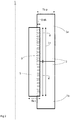
- Figure 1 shows a cross-section of an example connection assembly for connecting two pipes, 1a and 1b.
- the pipes have an end portion 2, a wall thickness Tk-p and an inner diameter D-p.
- the pipes have internal threads 3 on an inner surface of the pipe 1a, 1b.
- the internal threads are arranged over a distance d from the end portion 2 of the pipe and extend substantially parallel or parallel along a longitudinal axis L of the pipes 1a, 1b.
- a shoulder 4, at the distance d, indicates an end of the internal threads of the pipes.
- connection assembly also comprises a tubular connection member 5 having external threads 3 at an outer surface that extend substantially parallel or parallel along a longitudinal axis L of the pipes 1a, 1b.
- the threads are adapted to engage with the internal threads 3 of the pipes 1a, 1b.
- a length of the threaded inner surface d of each pipe 1a, 1b is substantially equal to, or equal to, half the length I-t of the tubular connection member 5.
- the tubular connection member has a wall thickness Tk-t and an inner diameter D-t.
- the tubular connection member 5 has an outer circumference adapted to be engaged with the inner circumference of the pipes.
- the tubular connection member has an outer diameter adapted to be inserted into the bores of the pipes 1a, 1b.
- the outer surface of the connection member can engage with the inner surface of the pipes 1a, 1b.
- both pipes are fully engaged with the tubular connection member 5.
- the end portions 2 of the pipes are in contact with each other.
- the threads 3 may be square or not. Threads may be radiused at a base of threads. The threads may be dimensioned with loadbearing flanges at different thread angles, such as 75° or more. According to some aspects, the internal threads form a helical ridge and the external threads forms a corresponding helical ridge, which engages the helical ridge of the internal thread.
- the internal and external threads are preferably the same in height, shape and form.
- the rotation of the internal and external threads 3 are the same direction as the rotation of a drill. Thus, if drilling is done in a right rotation, the threads are right-handed threads.
- the ratio of an inner diameter of the pipe D-p to a length I-t of the tubular connection member 5 is for example between 2:3 and 1:4.
- the ratio may be at least 2:3, or at least 1:2, or at least 1:3.
- the ratio of a thickness of a wall Tk-p of the pipe to a length I-t of the tubular connection member 5 is for example between 1:50 and 1:10.
- the ratio may be at least 1:30, or at least 1:25, or at least 1:20.
- the pipes may have a length of 1 to 12-meter.
- the inner diameter D-p of the pipes varies depending on the use of the pipes 1a, 1b, but may be between 180 and 250 mm, or between 195 and 205 mm.
- the thickness of the wall Tk-p of the pipes varies likewise. The thickness may be between 5 and 20 mm, or between 10 and 15 mm.
- the length I-t of the tubular connection member may thus be between 100 and 750 mm.
- pipes In standard ground drilling, e.g. in preparation of grounds prior to building houses and the like, pipes may have a wall thickness Tk-p of about 12.5 mm, an inner diameter D-p of about 203 mm.
- the length I-t of the tubular connection member may then be about 320 mm.
- the threads may have a depth D-th such that the total thickness Tk-t of the wall of the connection member plus the thickness Tk-p of the wall of the pipes is larger than the thickness of the walls of the pipes 1a, 1b (Tk-p + Tk-t > Tk-p).
- the depth of threads D-th on the internal surface of the pipes and on the outer surface of the connection member is for example between one eighth and one third of the thickness Tk-p of the wall of the pipe.
- the depth of threads D-th may be less than one sixth of the thickness Tk-p of the wall of the pipe.
- the depth of the threads 3 may be at the most one fourth of the thickness Tk-p of the wall of the pipes 1a, 1b.
- the thickness Tk-t of the wall of the tubular connection member 5 is preferably the same asthat of the pipes.
- the depth of threads on the external surface of the connection member is for example between one eight and one third of the thickness Tk-t of the wall of the tubular connection member.
- the depth of threads D-th may be less than one sixth of the thickness Tk-t of the wall.
- the depth of the threads 3 may be at the most one fourth of the thickness Tk-t of the wall.
- the tubular connection member 5 can be manufactured from the same or a different material than the pipes.
- the tubular connection member 5 may be manufactured from the same as a material of pipes. Examples of materials may be steel, stainless-steel.
- the tubular connection member 5 has for example end portions 6 as shown in figure 1 .
- the end portion 6 may abut against the shoulder 4.
- the end portion 6 comprises an angled surface.
- the angle ⁇ of the angled surface in relation to longitudinal axis L may be between 95 and 175°, or between 115 and 155°, or between 125 and 145°, or between 130 and 140°.
- An angle ⁇ of more than 125° or between 130 and 140° increases ease of transport of materials and fluids through the pipes.
- a shoulder 4 is not present.
- the external threads 3 on the tubular connection member 5 are adapted to be moved past the internal threads of the pipes, thereby preventing the tubular connection member from being unscrewed from the pipes if the drill rotates backwards.
Landscapes
- Engineering & Computer Science (AREA)
- Life Sciences & Earth Sciences (AREA)
- Geology (AREA)
- Mining & Mineral Resources (AREA)
- Mechanical Engineering (AREA)
- Physics & Mathematics (AREA)
- Environmental & Geological Engineering (AREA)
- Fluid Mechanics (AREA)
- General Life Sciences & Earth Sciences (AREA)
- Geochemistry & Mineralogy (AREA)
- Earth Drilling (AREA)
Claims (8)
- Ensemble de connexion pour raccorder des tuyaux pendant le forage, comprenant- deux tuyaux (1a, 1b) ayant des filetages internes (3) sur une surface intérieure du tuyau, disposés à une partie d'extrémité (2) du tuyau sur une distance (d),- un élément de raccordement tubulaire (5) ayant des filetages externes (3) au niveau d'une surface externe adaptée pour s'engager avec les filetages internes des tuyaux (1a, 1b),l'élément de raccordement tubulaire (5) a un diamètre extérieur adapté pour être inséré dans des alésages des tuyaux (1a, 1b), de sorte que les tuyaux (1a, 1b) sont en contact l'un avec l'autre lorsque l'élément de raccordement tubulaire (5) est disposé dans les alésages et les deux tuyaux sont entièrement engagés dans l'élément de raccordement tubulaire, dans lequel un épaulement (4) à la distance (d) indique une extrémité des filetages internes des tuyaux (1a, 1b) et caractérisé en ce que l'élément de raccordement tubulaire (5) a des parties d'extrémité (6) qui butent contre l'épaulement et la partie d'extrémité (6) comprend une surface angulaire, de sorte qu'un angle (a) de la surface angulaire par rapport à l'axe longitudinal (L) est supérieur à 125°, et dans lequel les filetages interne et externe (3) s'étendent parallèlement le long d'un axe longitudinal (L) des tuyaux (1a, 1b) et les filetages interne et externe ont la même longueur et la même hauteur et les filets ne sont pas coniques.
- Ensemble de connexion selon l'une quelconque des revendications précédentes, dans lequel les filetages interne et externe sont carrés.
- Ensemble de connexion selon l'une quelconque des revendications précédentes, dans lequel le rapport entre un diamètre interne (D-p) des tuyaux (1a, 1b) et une longueur (I-t) de l'élément de raccordement tubulaire (5) est compris entre 2:3 et 1:4.
- Ensemble de connexion selon l'une quelconque des revendications précédentes, dans lequel le rapport entre une épaisseur de paroi (Tk-p) des tuyaux (1a, 1b) et une longueur (I-t) de l'élément de raccordement tubulaire (5) est compris entre 1:50 et 1:10.
- Ensemble de connexion selon l'une quelconque des revendications précédentes, dans lequel une profondeur (D-th) des filetages (3) est inférieure à un sixième d'une épaisseur (Tk-p) de la paroi des tuyaux (1a, 1b).
- Ensemble de connexion selon l'une quelconque des revendications précédentes, dans lequel un matériau de l'élément de raccordement tubulaire (5) est le même qu'un matériau des tuyaux (1a, 1 b).
- Ensemble de connexion selon l'une quelconque des revendications précédentes, dans lequel l'angle (a) de la surface angulaire par rapport à l'axe longitudinal (L) est supérieur à 135°.
- Ensemble de connexion selon l'une quelconque des revendications précédentes, dans lequel les filetages interne et externe (3) sont tournés dans la même direction que le sens de rotation d'un foret.
Applications Claiming Priority (1)
| Application Number | Priority Date | Filing Date | Title |
|---|---|---|---|
| SE1851224 | 2018-10-08 |
Publications (2)
| Publication Number | Publication Date |
|---|---|
| EP3636873A1 EP3636873A1 (fr) | 2020-04-15 |
| EP3636873B1 true EP3636873B1 (fr) | 2021-05-05 |
Family
ID=67437419
Family Applications (1)
| Application Number | Title | Priority Date | Filing Date |
|---|---|---|---|
| EP19181463.1A Active EP3636873B1 (fr) | 2018-10-08 | 2019-06-20 | Ensemble de connexion pour raccorder des tuyaux |
Country Status (2)
| Country | Link |
|---|---|
| EP (1) | EP3636873B1 (fr) |
| DK (1) | DK3636873T3 (fr) |
Family Cites Families (6)
| Publication number | Priority date | Publication date | Assignee | Title |
|---|---|---|---|---|
| US3114566A (en) * | 1961-04-21 | 1963-12-17 | Kobe Inc | Shrink fit tubing joint |
| US3361448A (en) | 1965-09-27 | 1968-01-02 | Dominion Magnesium Ltd | Magnesium alloy drill rod assembly with ceramic coated coupling member |
| FR1583421A (fr) * | 1968-02-20 | 1969-10-31 | ||
| EP0205421A1 (fr) | 1984-11-23 | 1986-12-30 | WATTS, John, Dawson | Connecteur pour colonnes de production de puits de petrole |
| DE3825995C1 (fr) * | 1988-07-28 | 1989-10-19 | Mannesmann Ag, 4000 Duesseldorf, De | |
| US5895079A (en) * | 1996-02-21 | 1999-04-20 | Kenneth J. Carstensen | Threaded connections utilizing composite materials |
-
2019
- 2019-06-20 EP EP19181463.1A patent/EP3636873B1/fr active Active
- 2019-06-20 DK DK19181463.1T patent/DK3636873T3/da active
Also Published As
| Publication number | Publication date |
|---|---|
| DK3636873T3 (da) | 2021-07-26 |
| EP3636873A1 (fr) | 2020-04-15 |
Similar Documents
| Publication | Publication Date | Title |
|---|---|---|
| US7690697B2 (en) | Thread form for tubular connections | |
| US6609735B1 (en) | Threaded and coupled connection for improved fatigue resistance | |
| RU2345268C1 (ru) | Соединение труб | |
| US11754207B2 (en) | Thread form and threaded article | |
| US11598159B2 (en) | Coupling for connecting downhole tubulars | |
| RU2606008C2 (ru) | Резьбовое соединение с низким моментом свинчивания | |
| WO2003097991A1 (fr) | Joint filete pour train de tiges pour forage de roches par percussion | |
| EP3636873B1 (fr) | Ensemble de connexion pour raccorder des tuyaux | |
| US20200173584A1 (en) | Drill pipe | |
| US10240402B1 (en) | End fitting for sucker rods | |
| US4773479A (en) | Corrosion guard tubing nipple | |
| EP3356607B1 (fr) | Pieu | |
| RU2232865C2 (ru) | Насосная штанга | |
| RU2248438C1 (ru) | Буровая штанга | |
| US10443319B2 (en) | End fitting for sucker rods | |
| RU210115U1 (ru) | Труба бурильная с двухупорными замками уменьшенного наружного диаметра | |
| RU14995U1 (ru) | Соединение насосно-компрессорных или бурильных труб |
Legal Events
| Date | Code | Title | Description |
|---|---|---|---|
| PUAI | Public reference made under article 153(3) epc to a published international application that has entered the european phase |
Free format text: ORIGINAL CODE: 0009012 |
|
| STAA | Information on the status of an ep patent application or granted ep patent |
Free format text: STATUS: THE APPLICATION HAS BEEN PUBLISHED |
|
| AK | Designated contracting states |
Kind code of ref document: A1 Designated state(s): AL AT BE BG CH CY CZ DE DK EE ES FI FR GB GR HR HU IE IS IT LI LT LU LV MC MK MT NL NO PL PT RO RS SE SI SK SM TR |
|
| AX | Request for extension of the european patent |
Extension state: BA ME |
|
| STAA | Information on the status of an ep patent application or granted ep patent |
Free format text: STATUS: REQUEST FOR EXAMINATION WAS MADE |
|
| 17P | Request for examination filed |
Effective date: 20200930 |
|
| RBV | Designated contracting states (corrected) |
Designated state(s): AL AT BE BG CH CY CZ DE DK EE ES FI FR GB GR HR HU IE IS IT LI LT LU LV MC MK MT NL NO PL PT RO RS SE SI SK SM TR |
|
| STAA | Information on the status of an ep patent application or granted ep patent |
Free format text: STATUS: EXAMINATION IS IN PROGRESS |
|
| 17Q | First examination report despatched |
Effective date: 20201211 |
|
| STAA | Information on the status of an ep patent application or granted ep patent |
Free format text: STATUS: EXAMINATION IS IN PROGRESS |
|
| GRAP | Despatch of communication of intention to grant a patent |
Free format text: ORIGINAL CODE: EPIDOSNIGR1 |
|
| STAA | Information on the status of an ep patent application or granted ep patent |
Free format text: STATUS: GRANT OF PATENT IS INTENDED |
|
| INTG | Intention to grant announced |
Effective date: 20210223 |
|
| GRAS | Grant fee paid |
Free format text: ORIGINAL CODE: EPIDOSNIGR3 |
|
| GRAA | (expected) grant |
Free format text: ORIGINAL CODE: 0009210 |
|
| STAA | Information on the status of an ep patent application or granted ep patent |
Free format text: STATUS: THE PATENT HAS BEEN GRANTED |
|
| AK | Designated contracting states |
Kind code of ref document: B1 Designated state(s): AL AT BE BG CH CY CZ DE DK EE ES FI FR GB GR HR HU IE IS IT LI LT LU LV MC MK MT NL NO PL PT RO RS SE SI SK SM TR |
|
| REG | Reference to a national code |
Ref country code: GB Ref legal event code: FG4D |
|
| REG | Reference to a national code |
Ref country code: CH Ref legal event code: EP |
|
| REG | Reference to a national code |
Ref country code: AT Ref legal event code: REF Ref document number: 1390025 Country of ref document: AT Kind code of ref document: T Effective date: 20210515 |
|
| REG | Reference to a national code |
Ref country code: DE Ref legal event code: R096 Ref document number: 602019004406 Country of ref document: DE |
|
| REG | Reference to a national code |
Ref country code: IE Ref legal event code: FG4D |
|
| REG | Reference to a national code |
Ref country code: FI Ref legal event code: FGE |
|
| REG | Reference to a national code |
Ref country code: SE Ref legal event code: TRGR |
|
| REG | Reference to a national code |
Ref country code: DK Ref legal event code: T3 Effective date: 20210721 |
|
| REG | Reference to a national code |
Ref country code: LT Ref legal event code: MG9D |
|
| REG | Reference to a national code |
Ref country code: NO Ref legal event code: T2 Effective date: 20210505 |
|
| REG | Reference to a national code |
Ref country code: AT Ref legal event code: MK05 Ref document number: 1390025 Country of ref document: AT Kind code of ref document: T Effective date: 20210505 |
|
| PG25 | Lapsed in a contracting state [announced via postgrant information from national office to epo] |
Ref country code: AT Free format text: LAPSE BECAUSE OF FAILURE TO SUBMIT A TRANSLATION OF THE DESCRIPTION OR TO PAY THE FEE WITHIN THE PRESCRIBED TIME-LIMIT Effective date: 20210505 Ref country code: BG Free format text: LAPSE BECAUSE OF FAILURE TO SUBMIT A TRANSLATION OF THE DESCRIPTION OR TO PAY THE FEE WITHIN THE PRESCRIBED TIME-LIMIT Effective date: 20210805 Ref country code: LT Free format text: LAPSE BECAUSE OF FAILURE TO SUBMIT A TRANSLATION OF THE DESCRIPTION OR TO PAY THE FEE WITHIN THE PRESCRIBED TIME-LIMIT Effective date: 20210505 Ref country code: HR Free format text: LAPSE BECAUSE OF FAILURE TO SUBMIT A TRANSLATION OF THE DESCRIPTION OR TO PAY THE FEE WITHIN THE PRESCRIBED TIME-LIMIT Effective date: 20210505 |
|
| PG25 | Lapsed in a contracting state [announced via postgrant information from national office to epo] |
Ref country code: PT Free format text: LAPSE BECAUSE OF FAILURE TO SUBMIT A TRANSLATION OF THE DESCRIPTION OR TO PAY THE FEE WITHIN THE PRESCRIBED TIME-LIMIT Effective date: 20210906 Ref country code: RS Free format text: LAPSE BECAUSE OF FAILURE TO SUBMIT A TRANSLATION OF THE DESCRIPTION OR TO PAY THE FEE WITHIN THE PRESCRIBED TIME-LIMIT Effective date: 20210505 Ref country code: PL Free format text: LAPSE BECAUSE OF FAILURE TO SUBMIT A TRANSLATION OF THE DESCRIPTION OR TO PAY THE FEE WITHIN THE PRESCRIBED TIME-LIMIT Effective date: 20210505 Ref country code: LV Free format text: LAPSE BECAUSE OF FAILURE TO SUBMIT A TRANSLATION OF THE DESCRIPTION OR TO PAY THE FEE WITHIN THE PRESCRIBED TIME-LIMIT Effective date: 20210505 Ref country code: IS Free format text: LAPSE BECAUSE OF FAILURE TO SUBMIT A TRANSLATION OF THE DESCRIPTION OR TO PAY THE FEE WITHIN THE PRESCRIBED TIME-LIMIT Effective date: 20210905 Ref country code: GR Free format text: LAPSE BECAUSE OF FAILURE TO SUBMIT A TRANSLATION OF THE DESCRIPTION OR TO PAY THE FEE WITHIN THE PRESCRIBED TIME-LIMIT Effective date: 20210806 |
|
| REG | Reference to a national code |
Ref country code: NL Ref legal event code: MP Effective date: 20210505 |
|
| PG25 | Lapsed in a contracting state [announced via postgrant information from national office to epo] |
Ref country code: NL Free format text: LAPSE BECAUSE OF FAILURE TO SUBMIT A TRANSLATION OF THE DESCRIPTION OR TO PAY THE FEE WITHIN THE PRESCRIBED TIME-LIMIT Effective date: 20210505 |
|
| PG25 | Lapsed in a contracting state [announced via postgrant information from national office to epo] |
Ref country code: ES Free format text: LAPSE BECAUSE OF FAILURE TO SUBMIT A TRANSLATION OF THE DESCRIPTION OR TO PAY THE FEE WITHIN THE PRESCRIBED TIME-LIMIT Effective date: 20210505 Ref country code: EE Free format text: LAPSE BECAUSE OF FAILURE TO SUBMIT A TRANSLATION OF THE DESCRIPTION OR TO PAY THE FEE WITHIN THE PRESCRIBED TIME-LIMIT Effective date: 20210505 Ref country code: SK Free format text: LAPSE BECAUSE OF FAILURE TO SUBMIT A TRANSLATION OF THE DESCRIPTION OR TO PAY THE FEE WITHIN THE PRESCRIBED TIME-LIMIT Effective date: 20210505 Ref country code: RO Free format text: LAPSE BECAUSE OF FAILURE TO SUBMIT A TRANSLATION OF THE DESCRIPTION OR TO PAY THE FEE WITHIN THE PRESCRIBED TIME-LIMIT Effective date: 20210505 Ref country code: SM Free format text: LAPSE BECAUSE OF FAILURE TO SUBMIT A TRANSLATION OF THE DESCRIPTION OR TO PAY THE FEE WITHIN THE PRESCRIBED TIME-LIMIT Effective date: 20210505 Ref country code: CZ Free format text: LAPSE BECAUSE OF FAILURE TO SUBMIT A TRANSLATION OF THE DESCRIPTION OR TO PAY THE FEE WITHIN THE PRESCRIBED TIME-LIMIT Effective date: 20210505 |
|
| REG | Reference to a national code |
Ref country code: DE Ref legal event code: R097 Ref document number: 602019004406 Country of ref document: DE |
|
| REG | Reference to a national code |
Ref country code: BE Ref legal event code: MM Effective date: 20210630 |
|
| PLBE | No opposition filed within time limit |
Free format text: ORIGINAL CODE: 0009261 |
|
| STAA | Information on the status of an ep patent application or granted ep patent |
Free format text: STATUS: NO OPPOSITION FILED WITHIN TIME LIMIT |
|
| PG25 | Lapsed in a contracting state [announced via postgrant information from national office to epo] |
Ref country code: MC Free format text: LAPSE BECAUSE OF FAILURE TO SUBMIT A TRANSLATION OF THE DESCRIPTION OR TO PAY THE FEE WITHIN THE PRESCRIBED TIME-LIMIT Effective date: 20210505 Ref country code: LU Free format text: LAPSE BECAUSE OF NON-PAYMENT OF DUE FEES Effective date: 20210620 |
|
| 26N | No opposition filed |
Effective date: 20220208 |
|
| PG25 | Lapsed in a contracting state [announced via postgrant information from national office to epo] |
Ref country code: IE Free format text: LAPSE BECAUSE OF NON-PAYMENT OF DUE FEES Effective date: 20210620 |
|
| PG25 | Lapsed in a contracting state [announced via postgrant information from national office to epo] |
Ref country code: IS Free format text: LAPSE BECAUSE OF FAILURE TO SUBMIT A TRANSLATION OF THE DESCRIPTION OR TO PAY THE FEE WITHIN THE PRESCRIBED TIME-LIMIT Effective date: 20210905 Ref country code: FR Free format text: LAPSE BECAUSE OF NON-PAYMENT OF DUE FEES Effective date: 20210705 Ref country code: AL Free format text: LAPSE BECAUSE OF FAILURE TO SUBMIT A TRANSLATION OF THE DESCRIPTION OR TO PAY THE FEE WITHIN THE PRESCRIBED TIME-LIMIT Effective date: 20210505 |
|
| PG25 | Lapsed in a contracting state [announced via postgrant information from national office to epo] |
Ref country code: IT Free format text: LAPSE BECAUSE OF FAILURE TO SUBMIT A TRANSLATION OF THE DESCRIPTION OR TO PAY THE FEE WITHIN THE PRESCRIBED TIME-LIMIT Effective date: 20210505 Ref country code: BE Free format text: LAPSE BECAUSE OF NON-PAYMENT OF DUE FEES Effective date: 20210630 |
|
| REG | Reference to a national code |
Ref country code: CH Ref legal event code: PL |
|
| PG25 | Lapsed in a contracting state [announced via postgrant information from national office to epo] |
Ref country code: LI Free format text: LAPSE BECAUSE OF NON-PAYMENT OF DUE FEES Effective date: 20220630 Ref country code: CH Free format text: LAPSE BECAUSE OF NON-PAYMENT OF DUE FEES Effective date: 20220630 |
|
| PGFP | Annual fee paid to national office [announced via postgrant information from national office to epo] |
Ref country code: SE Payment date: 20230315 Year of fee payment: 5 |
|
| PG25 | Lapsed in a contracting state [announced via postgrant information from national office to epo] |
Ref country code: CY Free format text: LAPSE BECAUSE OF FAILURE TO SUBMIT A TRANSLATION OF THE DESCRIPTION OR TO PAY THE FEE WITHIN THE PRESCRIBED TIME-LIMIT Effective date: 20210505 |
|
| PG25 | Lapsed in a contracting state [announced via postgrant information from national office to epo] |
Ref country code: HU Free format text: LAPSE BECAUSE OF FAILURE TO SUBMIT A TRANSLATION OF THE DESCRIPTION OR TO PAY THE FEE WITHIN THE PRESCRIBED TIME-LIMIT; INVALID AB INITIO Effective date: 20190620 |
|
| PGFP | Annual fee paid to national office [announced via postgrant information from national office to epo] |
Ref country code: NO Payment date: 20230622 Year of fee payment: 5 Ref country code: DK Payment date: 20230615 Year of fee payment: 5 |
|
| PGFP | Annual fee paid to national office [announced via postgrant information from national office to epo] |
Ref country code: FI Payment date: 20230620 Year of fee payment: 5 |
|
| PGFP | Annual fee paid to national office [announced via postgrant information from national office to epo] |
Ref country code: GB Payment date: 20230810 Year of fee payment: 5 |
|
| PGFP | Annual fee paid to national office [announced via postgrant information from national office to epo] |
Ref country code: DE Payment date: 20231124 Year of fee payment: 5 |
|
| PG25 | Lapsed in a contracting state [announced via postgrant information from national office to epo] |
Ref country code: MK Free format text: LAPSE BECAUSE OF FAILURE TO SUBMIT A TRANSLATION OF THE DESCRIPTION OR TO PAY THE FEE WITHIN THE PRESCRIBED TIME-LIMIT Effective date: 20210505 |