EP3636493A1 - Method, apparatus and storage medium for communicating with a rear vehicle - Google Patents
Method, apparatus and storage medium for communicating with a rear vehicle Download PDFInfo
- Publication number
- EP3636493A1 EP3636493A1 EP19202565.8A EP19202565A EP3636493A1 EP 3636493 A1 EP3636493 A1 EP 3636493A1 EP 19202565 A EP19202565 A EP 19202565A EP 3636493 A1 EP3636493 A1 EP 3636493A1
- Authority
- EP
- European Patent Office
- Prior art keywords
- congestion
- vehicle
- present vehicle
- mood
- information
- Prior art date
- Legal status (The legal status is an assumption and is not a legal conclusion. Google has not performed a legal analysis and makes no representation as to the accuracy of the status listed.)
- Granted
Links
- 238000000034 method Methods 0.000 title claims abstract description 33
- 230000036651 mood Effects 0.000 claims description 43
- 238000004891 communication Methods 0.000 claims description 21
- 230000003993 interaction Effects 0.000 claims description 15
- 230000006399 behavior Effects 0.000 claims description 14
- 230000008921 facial expression Effects 0.000 claims description 14
- 238000004590 computer program Methods 0.000 claims description 5
- 230000006870 function Effects 0.000 description 8
- 230000003287 optical effect Effects 0.000 description 8
- 206010039203 Road traffic accident Diseases 0.000 description 5
- 238000010586 diagram Methods 0.000 description 4
- 206010022998 Irritability Diseases 0.000 description 2
- 238000013019 agitation Methods 0.000 description 2
- 238000004458 analytical method Methods 0.000 description 2
- 230000002093 peripheral effect Effects 0.000 description 2
- 230000000644 propagated effect Effects 0.000 description 2
- 230000002159 abnormal effect Effects 0.000 description 1
- 238000003491 array Methods 0.000 description 1
- 238000004883 computer application Methods 0.000 description 1
- 238000005516 engineering process Methods 0.000 description 1
- 230000002708 enhancing effect Effects 0.000 description 1
- 238000012986 modification Methods 0.000 description 1
- 230000004048 modification Effects 0.000 description 1
- 230000006855 networking Effects 0.000 description 1
- 239000004065 semiconductor Substances 0.000 description 1
- 238000006467 substitution reaction Methods 0.000 description 1
Images


Classifications
-
- B—PERFORMING OPERATIONS; TRANSPORTING
- B60—VEHICLES IN GENERAL
- B60Q—ARRANGEMENT OF SIGNALLING OR LIGHTING DEVICES, THE MOUNTING OR SUPPORTING THEREOF OR CIRCUITS THEREFOR, FOR VEHICLES IN GENERAL
- B60Q1/00—Arrangement of optical signalling or lighting devices, the mounting or supporting thereof or circuits therefor
- B60Q1/26—Arrangement of optical signalling or lighting devices, the mounting or supporting thereof or circuits therefor the devices being primarily intended to indicate the vehicle, or parts thereof, or to give signals, to other traffic
- B60Q1/50—Arrangement of optical signalling or lighting devices, the mounting or supporting thereof or circuits therefor the devices being primarily intended to indicate the vehicle, or parts thereof, or to give signals, to other traffic for indicating other intentions or conditions, e.g. request for waiting or overtaking
-
- B—PERFORMING OPERATIONS; TRANSPORTING
- B60—VEHICLES IN GENERAL
- B60Q—ARRANGEMENT OF SIGNALLING OR LIGHTING DEVICES, THE MOUNTING OR SUPPORTING THEREOF OR CIRCUITS THEREFOR, FOR VEHICLES IN GENERAL
- B60Q1/00—Arrangement of optical signalling or lighting devices, the mounting or supporting thereof or circuits therefor
- B60Q1/26—Arrangement of optical signalling or lighting devices, the mounting or supporting thereof or circuits therefor the devices being primarily intended to indicate the vehicle, or parts thereof, or to give signals, to other traffic
- B60Q1/2611—Indicating devices mounted on the roof of the vehicle
-
- B—PERFORMING OPERATIONS; TRANSPORTING
- B60—VEHICLES IN GENERAL
- B60Q—ARRANGEMENT OF SIGNALLING OR LIGHTING DEVICES, THE MOUNTING OR SUPPORTING THEREOF OR CIRCUITS THEREFOR, FOR VEHICLES IN GENERAL
- B60Q1/00—Arrangement of optical signalling or lighting devices, the mounting or supporting thereof or circuits therefor
- B60Q1/26—Arrangement of optical signalling or lighting devices, the mounting or supporting thereof or circuits therefor the devices being primarily intended to indicate the vehicle, or parts thereof, or to give signals, to other traffic
- B60Q1/50—Arrangement of optical signalling or lighting devices, the mounting or supporting thereof or circuits therefor the devices being primarily intended to indicate the vehicle, or parts thereof, or to give signals, to other traffic for indicating other intentions or conditions, e.g. request for waiting or overtaking
- B60Q1/503—Arrangement of optical signalling or lighting devices, the mounting or supporting thereof or circuits therefor the devices being primarily intended to indicate the vehicle, or parts thereof, or to give signals, to other traffic for indicating other intentions or conditions, e.g. request for waiting or overtaking using luminous text or symbol displays in or on the vehicle, e.g. static text
- B60Q1/5035—Arrangement of optical signalling or lighting devices, the mounting or supporting thereof or circuits therefor the devices being primarily intended to indicate the vehicle, or parts thereof, or to give signals, to other traffic for indicating other intentions or conditions, e.g. request for waiting or overtaking using luminous text or symbol displays in or on the vehicle, e.g. static text electronic displays
- B60Q1/5037—Arrangement of optical signalling or lighting devices, the mounting or supporting thereof or circuits therefor the devices being primarily intended to indicate the vehicle, or parts thereof, or to give signals, to other traffic for indicating other intentions or conditions, e.g. request for waiting or overtaking using luminous text or symbol displays in or on the vehicle, e.g. static text electronic displays the display content changing automatically, e.g. depending on traffic situation
-
- B—PERFORMING OPERATIONS; TRANSPORTING
- B60—VEHICLES IN GENERAL
- B60Q—ARRANGEMENT OF SIGNALLING OR LIGHTING DEVICES, THE MOUNTING OR SUPPORTING THEREOF OR CIRCUITS THEREFOR, FOR VEHICLES IN GENERAL
- B60Q1/00—Arrangement of optical signalling or lighting devices, the mounting or supporting thereof or circuits therefor
- B60Q1/26—Arrangement of optical signalling or lighting devices, the mounting or supporting thereof or circuits therefor the devices being primarily intended to indicate the vehicle, or parts thereof, or to give signals, to other traffic
- B60Q1/50—Arrangement of optical signalling or lighting devices, the mounting or supporting thereof or circuits therefor the devices being primarily intended to indicate the vehicle, or parts thereof, or to give signals, to other traffic for indicating other intentions or conditions, e.g. request for waiting or overtaking
- B60Q1/545—Arrangement of optical signalling or lighting devices, the mounting or supporting thereof or circuits therefor the devices being primarily intended to indicate the vehicle, or parts thereof, or to give signals, to other traffic for indicating other intentions or conditions, e.g. request for waiting or overtaking for indicating other traffic conditions, e.g. fog, heavy traffic
-
- B—PERFORMING OPERATIONS; TRANSPORTING
- B60—VEHICLES IN GENERAL
- B60R—VEHICLES, VEHICLE FITTINGS, OR VEHICLE PARTS, NOT OTHERWISE PROVIDED FOR
- B60R11/00—Arrangements for holding or mounting articles, not otherwise provided for
- B60R11/04—Mounting of cameras operative during drive; Arrangement of controls thereof relative to the vehicle
-
- G—PHYSICS
- G06—COMPUTING; CALCULATING OR COUNTING
- G06V—IMAGE OR VIDEO RECOGNITION OR UNDERSTANDING
- G06V20/00—Scenes; Scene-specific elements
- G06V20/50—Context or environment of the image
- G06V20/59—Context or environment of the image inside of a vehicle, e.g. relating to seat occupancy, driver state or inner lighting conditions
- G06V20/597—Recognising the driver's state or behaviour, e.g. attention or drowsiness
-
- G—PHYSICS
- G06—COMPUTING; CALCULATING OR COUNTING
- G06V—IMAGE OR VIDEO RECOGNITION OR UNDERSTANDING
- G06V40/00—Recognition of biometric, human-related or animal-related patterns in image or video data
- G06V40/10—Human or animal bodies, e.g. vehicle occupants or pedestrians; Body parts, e.g. hands
- G06V40/16—Human faces, e.g. facial parts, sketches or expressions
- G06V40/174—Facial expression recognition
-
- G—PHYSICS
- G08—SIGNALLING
- G08G—TRAFFIC CONTROL SYSTEMS
- G08G1/00—Traffic control systems for road vehicles
- G08G1/16—Anti-collision systems
- G08G1/161—Decentralised systems, e.g. inter-vehicle communication
- G08G1/162—Decentralised systems, e.g. inter-vehicle communication event-triggered
-
- B—PERFORMING OPERATIONS; TRANSPORTING
- B60—VEHICLES IN GENERAL
- B60Q—ARRANGEMENT OF SIGNALLING OR LIGHTING DEVICES, THE MOUNTING OR SUPPORTING THEREOF OR CIRCUITS THEREFOR, FOR VEHICLES IN GENERAL
- B60Q1/00—Arrangement of optical signalling or lighting devices, the mounting or supporting thereof or circuits therefor
- B60Q1/26—Arrangement of optical signalling or lighting devices, the mounting or supporting thereof or circuits therefor the devices being primarily intended to indicate the vehicle, or parts thereof, or to give signals, to other traffic
- B60Q1/50—Arrangement of optical signalling or lighting devices, the mounting or supporting thereof or circuits therefor the devices being primarily intended to indicate the vehicle, or parts thereof, or to give signals, to other traffic for indicating other intentions or conditions, e.g. request for waiting or overtaking
- B60Q1/507—Arrangement of optical signalling or lighting devices, the mounting or supporting thereof or circuits therefor the devices being primarily intended to indicate the vehicle, or parts thereof, or to give signals, to other traffic for indicating other intentions or conditions, e.g. request for waiting or overtaking specific to autonomous vehicles
Definitions
- the present disclosure relates to computer application technologies, and particularly to a method, apparatus and storage medium for communicating with a rear vehicle.
- the present disclosure provides a method, apparatus, computer device and storage medium for communicating with a rear vehicle.
- a method for communicating with a rear vehicle comprising:
- the present vehicle determining that it is currently in a congestion scenario comprises: the present vehicle determines that the present vehicle is currently in the congestion scenario if the present vehicle determines that a duration of the following state exceeds a predetermined duration: the current traffic slowly advances at a speed below a predetermined threshold.
- the obtaining the congestion condition information comprises: the present vehicle obtaining the congestion condition information by interacting with an Internet-connected intelligent transportation system.
- the congestion prompt information at least includes: a cause of congestion; the cause of congestion includes at least one of the following: an accident ahead, heavy traffic ahead, temporary road closures ahead, and congestion caused by weather.
- the method further comprises:
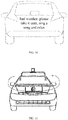
- the present vehicle determining whether the driver of the rear vehicle is in a road rage mood comprises: the present vehicle obtaining facial expressions and/or behaviors of the driver of the rear vehicle through a camera at the tail of the present vehicle, and determining whether the driver of the rear vehicle is in the road rage mood by analyzing the facial expressions and/or behaviors.
- the method further comprises: upon determining that the driver of the rear vehicle is in the road rage mood, the present vehicle turning on a streamline type lamp strip on the roof of the present vehicle and/or an annular lamp strip at the tail of the present vehicle to sooth the mood of the driver of the rear vehicle in a flowing pattern of atmosphere lamps.
- An apparatus for communicating with a rear vehicle comprising: an information interaction unit and a first communicating unit; the information interaction unit is configured to obtain congestion condition information upon determining that the present vehicle is currently in a congestion scenario; the first communication unit is configured to generate congestion prompt information for the rear vehicle according to the congestion condition information, and display the congestion prompt information on a screen at a tail of the present vehicle.
- the information interaction unit determines that the present vehicle is currently in the congestion scenario if the information interaction unit determines that a duration of the following state exceeds a predetermined duration: the current traffic slowly advances at a speed below a predetermined threshold.
- the information interaction unit obtains the congestion condition information by interacting with an Internet-connected intelligent transportation system.
- the congestion prompt information at least includes: a cause of congestion; the cause of congestion includes at least one of the following: an accident ahead, heavy traffic ahead, temporary road closures ahead, and congestion caused by weather.
- the apparatus further comprises: a second communication unit; the second communication unit is configured to determine whether the driver of the rear vehicle is in a road rage mood, and if yes, generate mood-soothing information and display the mood-soothing information on the screen.
- the second communication unit obtains facial expressions and/or behaviors of the driver of the rear vehicle through a camera at the tail of the present vehicle, and determines whether the driver of the rear vehicle is in the road rage mood by analyzing the facial expressions and/or behaviors.
- the second communication unit is further configured to, upon determining that the driver of the rear vehicle is in the road rage mood, turn on a streamline type lamp strip on the roof of the present vehicle and/or an annular lamp strip at the tail of the present vehicle to sooth the mood of the driver of the rear vehicle in a flowing pattern of atmosphere lamps.
- a computer device comprising a memory, a processor and a computer program which is stored on the memory and runs on the processor, the processor, upon executing the program, implementing the above-mentioned method.
- a computer-readable storage medium on which a computer program is stored the program, when executed by the processor, implementing the aforesaid method.
- the present vehicle may obtain congestion condition information after determining that the present vehicle is currently in a congestion scenario, and generate congestion prompt information for the rear vehicle according to the congestion condition information, and display the congestion prompt information on a screen at a tail of the present vehicle, so that the rear vehicle can be enabled to learn about the congestion condition ahead in time without querying an APP on the mobile phone, such that the safety of vehicle travel is improved.
- the present disclosure provides a solution of communicating with a rear vehicle, and changing a present vehicle in a congestion scenario into an information source of the rear vehicle, thereby enhancing the travel safety of the rear vehicle.
- the present vehicle is a vehicle having an autonomous driving function.
- the present vehicle in the solution of the present disclosure may be an autonomous vehicle capable of achieving L5 autonomous driving level, namely, capable of autonomously achieving all operations of travel on urban roads and capable of accurately recognizing elements such as ambient environment factors, vehicles on the road surface, electrically-motored vehicles, bicycles and pedestrians, and additionally capable of interacting with an Internet-connected intelligent transportation system.
- L5 autonomous driving level namely, capable of autonomously achieving all operations of travel on urban roads and capable of accurately recognizing elements such as ambient environment factors, vehicles on the road surface, electrically-motored vehicles, bicycles and pedestrians, and additionally capable of interacting with an Internet-connected intelligent transportation system.
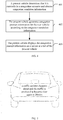
- the present vehicle in the solution of the present disclosure may be provided with a screen located at a tail of the present vehicle, a cameral located at the tail of the present vehicle, a streamline type lamp strip on a roof of the present vehicle and an annular lamp strip at the tail of the present vehicle.
- FIGS. 1-3 FIG. 1 is a schematic view showing a position of the screen and the camera according to the present disclosure
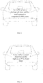
- FIG. 2 is a schematic view showing a position of a streamline type lamp strip on the roof of the present vehicle according to the present disclosure
- FIG. 3 is a schematic view showing a position of an annular lamp strip at the tail of the present vehicle according to the present disclosure.
- FIG. 4 is a flow chart of a method of communicating with a rear vehicle according to an embodiment of the present disclosure. As shown in FIG. 4 , the embodiment includes the following specific implementation mode.
- a present vehicle determines that it is currently in a congestion scenario and obtains congestion condition information.
- the present vehicle generates congestion prompt information for the rear vehicle according to the congestion condition information.
- the present vehicle displays the congestion prompt information on a screen at a tail of the present vehicle.
- the present vehicle When the present vehicle is driving on the road, it may determine whether it is currently in a congestion scenario in real time, and if it is in a congestion scenario, it may trigger a function of communicating with the rear vehicle.
- the present vehicle may determine that it is currently in the congestion scenario.
- the predetermined duration and the predetermined threshold may depend on actual needs.
- the predetermined duration may be 10 mins
- the predetermined threshold may be 10 km/h. That is to say, if the current traffic slowly advances at a speed lower than 10 km/h, and this state lasts for more than 10 mins, it may be determined that the present vehicle is currently in the congestion scenario.
- the present vehicle may obtain the congestion condition information. Specifically, the present vehicle may interact with the Internet-connected intelligent transportation system to obtain the congestion condition information.
- the present vehicle may generate congestion prompt information for the rear vehicle according to the obtained congestion condition information.
- the congestion prompt information may at least include: a cause of congestion.
- the cause of congestion may include, but is not limited to, an accident ahead, heavy traffic ahead, temporary road closures ahead, and congestion caused by weather.
- the congestion prompt information may further include some other information, such as a duration before the road becomes clear again. Specific content included is not limited here.
- the present vehicle may know that the congestion is caused by a traffic accident happening ahead, by interacting with the Internet-connected intelligent transportation system, and may know a distance of the traffic accident site from the present vehicle and happening time of the traffic accident by interacting with the Internet-connected intelligent transportation system, and furthermore may determine an average vehicle-removing time of a corresponding type of accidents by querying a pre-generated historical accident library, and thereby infer how long the road will become clear again.
- FIG. 5 is a first schematic view of information displayed on a screen at a tail of a present vehicle according to the present disclosure.
- the displayed content may be that a traffic accident happens ahead and the traffic is predicted to become clear again in 20mins.
- various forms of display such as text, graphics or the like may be employed, and are not limited to those shown in the figures.
- the present vehicle may know that the congestion is caused by heavy traffic ahead by interacting with the Internet-connected intelligent transportation system, and know a traffic index of the road segment in the same time period in the past and then determine whether the traffic is currently in the normal daily situation by interacting with the Internet-connected intelligent transportation system, and if the traffic is abnormal, may further query the Internet-connected intelligent transportation system to find out whether there is special road closure information on the current day.
- FIG. 6 is a second schematic view of information displayed on a screen at a tail of a present vehicle according to the present disclosure. As shown in FIG. 6 , the displayed content may be that the traffic is heavy during rush hour and the road segment is congested in 90% cases.
- FIG. 7 is a third schematic view of information displayed on a screen at a tail of a present vehicle according to the present disclosure. As shown in FIG. 7 , the displayed content may be that heavy traffic is caused ahead because the highway to ** is closed today.
- the present vehicle may acquire weather information and weather changes which are happening in a range of 10km around on the current day by interacting with the Internet-connected intelligent transportation system, and then perform synchronization of weather information and/or provide early warning of weather ahead through the screen.
- FIG. 8 is a fourth schematic view of information displayed on a screen at a tail of a present vehicle according to the present disclosure. As shown in FIG. 8 , the displayed content may be heavy rain, congestion 1km ahead, drive carefully.
- FIG. 9 is a fifth schematic view of information displayed on a screen at a tail of a present vehicle according to the present disclosure. As shown in FIG. 9 , the displayed content may be that it is raining 5km ahead in the direction to ** and continued congestion might caused.
- the rear vehicle can be enabled to learn about the congestion condition ahead in time without querying an APP on the mobile phone, so that the safety of vehicle travel is improved.
- the present vehicle may detect the mood of the driver of the rear vehicle, namely, determine whether the driver of the rear vehicle is in a road rage mood. Once determining that the driver of the rear vehicle is in the road rage mood, the present vehicle may generate mood-soothing information and display the mood-soothing information on the screen.
- the present vehicle may obtain facial expressions and/or behaviors of the driver of the rear vehicle through the camera at the tail of the present vehicle, and determine whether the driver of the rear vehicle is in the road rage mood by analyzing the obtained facial expressions and/or behaviors.
- the driver of the rear vehicle is in the road rage mood if it is found after analysis that the facial expressions of the driver of the rear vehicle show negative moods such as agitation and anger and the driver of the rear vehicle exhibits behaviors such as constantly looking out of the window to see situations ahead, patting the steering wheel, and opening and closing mouth (e.g., swearing).
- negative moods such as agitation and anger
- the driver of the rear vehicle exhibits behaviors such as constantly looking out of the window to see situations ahead, patting the steering wheel, and opening and closing mouth (e.g., swearing).
- the present vehicle may generate mood-soothing information and display the mood-soothing information on the screen.
- the mood-soothing information and congestion prompt information may be displayed on the screen alternatingly.
- FIG. 10 is a sixth schematic view of information displayed on a screen at a tail of a present vehicle according to the present disclosure.
- the displayed content may be: bad weather, please take it easy, sing a song and relax.
- the content displayed in FIG. 10 and the content displayed in FIG. 8 are displayed on the screen alternatingly.
- FIG. 11 is a schematic view showing a flow pattern of a lamp strip of the present vehicle according to the present disclosure.
- the present vehicle can become information source of the rear vehicle in a congestion scenario, and recognize the road rage mood of the driver of the rear vehicle and sooth him in time, so that the present vehicle really becomes a smart terminal travelling on the road, and the present vehicle becomes a smart transportation carrier which is trusted more and provides better safety.
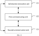
- FIG. 12 is a block diagram of an apparatus for communicating with a rear vehicle according to an embodiment of the present disclosure. As shown in FIG. 12 , the apparatus comprises: an information interaction unit 121 and a first communicating unit 122.
- the apparatus of the present application is applied in the present vehicle.
- the information interaction unit 121 is configured to obtain congestion condition information upon determining that a present vehicle is currently in a congestion scenario.
- the first communication unit 122 is configured to generate congestion prompt information for the rear vehicle according to the congestion condition information, and display the congestion prompt information on a screen at a tail of the present vehicle.
- the information interaction unit 121 determines that a duration of the following state exceeds a predetermined duration: the current traffic slowly advances at a speed below a predetermined threshold, and then determines that the present vehicle is currently in the congestion scenario.
- the predetermined duration and the predetermined threshold may depend on actual needs.
- the predetermined duration may be 10 mins
- the predetermined threshold may be 10 km/h. That is to say, if the current traffic slowly advances at a speed lower than 10 km/h, and this state lasts for more than 10 mins, it may be determined that the present vehicle is currently in the congestion scenario.
- the information interaction unit 121 may obtain the congestion condition information. Specifically, the information interaction unit 121 may interact with the Internet-connected intelligent transportation system to obtain the congestion condition information.
- the first communication unit 122 may generate congestion prompt information for the rear vehicle according to the obtained congestion condition information.
- the congestion prompt information may at least include: a cause of congestion.
- the cause of congestion may include, but is not limited to, an accident ahead, heavy traffic ahead, temporary road closures ahead, and congestion caused by weather.
- the congestion prompt information may further include some other information, such as a duration before the road becomes clear again. Specific content included is not limited here.
- the rear vehicle can be enabled to learn about the congestion condition ahead without querying an APP on the mobile phone, so that the safety of vehicle travel is improved.
- the apparatus may further comprise: a second communication unit 123 configured to determine whether the driver of the rear vehicle is in a road rage mood when in the congestion scenario, and if yes, generate mood-soothing information and display the mood-soothing information on the screen. That is to say, the second communication unit 123 may detect the mood of the driver of the rear vehicle, namely, determine whether the driver of the rear vehicle is in a road rage mood. Once determining that the driver of the rear vehicle is in the road rage mood, the second communication unit 123 may generate mood-soothing information and display the mood-soothing information on the screen.
- the second communication unit 123 may obtain facial expressions and/or behaviors of the driver of the rear vehicle through a camera at the tail of the present vehicle, and thereby determine whether the driver of the rear vehicle is in the road rage mood by analyzing the obtained facial expressions and/or behaviors.
- the driver of the rear vehicle is in the road rage mood if it is found after analysis that the facial expressions of the driver of the rear vehicle show negative moods such as agitation and anger and the driver of the rear vehicle exhibits behaviors such as constantly looking out of the window to see situations ahead, patting the steering wheel, and opening and closing mouth (e.g., swearing).
- negative moods such as agitation and anger
- the driver of the rear vehicle exhibits behaviors such as constantly looking out of the window to see situations ahead, patting the steering wheel, and opening and closing mouth (e.g., swearing).
- the second communication unit 123 may generate mood-soothing information and display the mood-soothing information on the screen.
- the mood-soothing information and congestion prompt information generated by the first communication unit 122 may be displayed on the screen alternatingly.
- the second communication unit 123 may further turn on the streamline type lamp strip on the roof of the present vehicle and/or the annular lamp strip at the tail of the present vehicle to sooth the mood of the driver of the rear vehicle in a flowing manner of atmosphere lamps.
- the present vehicle can become information source of the rear vehicle in a congestion scenario, and recognize the road rage mood of the driver of the rear vehicle and sooth him in time, so that the present vehicle really becomes a smart terminal travelling on the road, and the present vehicle becomes a smart transportation carrier which is trusted more and provides better safety.
- FIG. 13 illustrates a block diagram of an example computer system/server 12 adapted to implement an implementation mode of the present disclosure.
- the computer system/server 12 shown in FIG. 13 is only an example and should not bring about any limitation to the function and scope of use of the embodiments of the present disclosure.
- the computer system/server 12 is shown in the form of a general-purpose computing device.
- the components of computer system/server 12 may include, but are not limited to, one or more processors (processing units) 16, a memory 28, and a bus 18 that couples various system components including system memory 28 and the processor 16.
- Bus 18 represents one or more of several types of bus structures, including a memory bus or memory controller, a peripheral bus, an accelerated graphics port, and a processor or local bus using any of a variety of bus architectures.
- bus architectures include Industry Standard Architecture (ISA) bus, Micro Channel Architecture (MCA) bus, Enhanced ISA (EISA) bus, Video Electronics Standards Association (VESA) local bus, and Peripheral Component Interconnect (PCI) bus.
- Computer system/server 12 typically includes a variety of computer system readable media. Such media may be any available media that is accessible by computer system/server 12, and it includes both volatile and non-volatile media, removable and non-removable media.
- Memory 28 may include computer system readable media in the form of volatile memory, such as random access memory (RAM) 30 and/or cache memory 32.
- Computer system/server 12 may further include other removable/non-removable, volatile/non-volatile computer system storage media.
- storage system 34 may be provided for reading from and writing to a non-removable, non-volatile magnetic media (not shown in FIG. 13 and typically called a "hard drive").
- a magnetic disk drive for reading from and writing to a removable, non-volatile magnetic disk (e.g., a "floppy disk"), and an optical disk drive for reading from or writing to a removable, non-volatile optical disk such as a CD-ROM, DVD-ROM or other optical media
- each drive may be connected to bus 18 by one or more data media interfaces.
- the memory 28 may include at least one program product having a set (e.g., at least one) of program modules that are configured to carry out the functions of embodiments of the present disclosure.
- Program/utility 40 having a set (at least one) of program modules 42, may be stored in the system memory 28 by way of example, and not limitation, as well as an operating system, one or more disclosure programs, other program modules, and program data. Each of these examples or a certain combination thereof might include an implementation of a networking environment.
- Program modules 42 generally carry out the functions and/or methodologies of embodiments of the present disclosure.
- Computer system/server 12 may also communicate with one or more external devices 14 such as a keyboard, a pointing device, a display 24, etc.; with one or more devices that enable a user to interact with computer system/server 12; and/or with any devices (e.g., network card, modem, etc.) that enable computer system/server 12 to communicate with one or more other computing devices. Such communication may occur via Input/Output (I/O) interfaces 22. Still yet, computer system/server 12 may communicate with one or more networks such as a local area network (LAN), a general wide area network (WAN), and/or a public network (e.g., the Internet) via network adapter 20. As depicted in FIG.
- LAN local area network
- WAN wide area network
- public network e.g., the Internet
- network adapter 20 communicates with the other communication modules of computer system/server 12 via bus 18. It should be understood that although not shown, other hardware and/or software modules could be used in conjunction with computer system/server 12. Examples, include, but are not limited to: microcode, device drivers, redundant processing units, external disk drive arrays, RAID systems, tape drives, and data archival storage systems, etc.
- the processor 16 executes various function applications and data processing by running programs stored in the memory 28, for example, implement the method in the embodiment shown in FIG. 4 .
- the present disclosure meanwhile provides a computer-readable storage medium on which a computer program is stored, the program, when executed by the processor, implementing the method stated in the embodiment shown in FIG. 4 .
- the computer-readable medium of the present embodiment may employ any combinations of one or more computer-readable media.
- the machine readable medium may be a machine readable signal medium or a machine readable storage medium.
- a machine readable medium may include, but not limited to, an electronic, magnetic, optical, electromagnetic, infrared, or semiconductor system, apparatus, or device, or any suitable combination of the foregoing.
- the machine readable storage medium may be any tangible medium that include or store programs for use by an instruction execution system, apparatus or device or a combination thereof.
- the computer-readable signal medium may be included in a baseband or serve as a data signal propagated by part of a carrier, and it carries a computer-readable program code therein. Such propagated data signal may take many forms, including, but not limited to, electromagnetic signal, optical signal or any suitable combinations thereof.
- the computer-readable signal medium may further be any computer-readable medium besides the computer-readable storage medium, and the computer-readable medium may send, propagate or transmit a program for use by an instruction execution system, apparatus or device or a combination thereof.
- the program codes included by the computer-readable medium may be transmitted with any suitable medium, including, but not limited to radio, electric wire, optical cable, RF or the like, or any suitable combination thereof.
- Computer program code for carrying out operations disclosed herein may be written in one or more programming languages or any combination thereof. These programming languages include an object oriented programming language such as Java, Smalltalk, C++ or the like, and conventional procedural programming languages, such as the "C" programming language or similar programming languages.
- the program code may execute entirely on the user's computer, partly on the user's computer, as a stand-alone software package, partly on the user's computer and partly on a remote computer or entirely on the remote computer or server.
- the remote computer may be connected to the user's computer through any type of network, including a local area network (LAN) or a wide area network (WAN), or the connection may be made to an external computer (for example, through the Internet using an Internet Service Provider).
- LAN local area network
- WAN wide area network
- Internet Service Provider for example, AT&T, MCI, Sprint, EarthLink, MSN, GTE, etc.
- the revealed apparatus and method may be implemented in other ways.
- the above-described embodiments for the apparatus are only exemplary, e.g., the division of the units is merely logical one, and, in reality, they may be divided in other ways upon implementation.
- the units described as separate parts may be or may not be physically separated, the parts shown as units may be or may not be physical units, i.e., they may be located in one place, or distributed in a plurality of network units. One may select some or all the units to achieve the purpose of the embodiment according to the actual needs.
- functional units may be integrated in one processing unit, or they may be separate physical presences; or two or more units may be integrated in one unit.
- the integrated unit described above may be implemented in the form of hardware, or they may be implemented with hardware plus software functional units.
- the aforementioned integrated unit in the form of software function units may be stored in a computer readable storage medium.
- the aforementioned software function units are stored in a storage medium, including several instructions to instruct a computer device (a personal computer, server, or network equipment, etc.) or processor to perform some steps of the method described in the various embodiments of the present disclosure.
- the aforementioned storage medium includes various media that may store program codes, such as U disk, removable hard disk, Read-Only Memory (ROM), a Random Access Memory (RAM), magnetic disk, or an optical disk.
Landscapes
- Engineering & Computer Science (AREA)
- Mechanical Engineering (AREA)
- Physics & Mathematics (AREA)
- General Physics & Mathematics (AREA)
- Multimedia (AREA)
- Theoretical Computer Science (AREA)
- Health & Medical Sciences (AREA)
- General Health & Medical Sciences (AREA)
- Oral & Maxillofacial Surgery (AREA)
- Human Computer Interaction (AREA)
- Traffic Control Systems (AREA)
Abstract
Description
- The present application claims the priority of Chinese Patent Application No.
201811184764.5, filed on October 11, 2018 - The present disclosure relates to computer application technologies, and particularly to a method, apparatus and storage medium for communicating with a rear vehicle.
- Regarding current road conditions in all countries, as the number of motor vehicles increases abruptly, congestion often occurs due to weather, accidents, rush hour and other reasons.
- For a driver driving a vehicle on the road, he usually needs to learn about information such as a cause for congestion for example by querying an APP on a mobile phone, which will undoubtedly cause a certain travelling danger, thereby affecting the safety of the travel of the vehicle.
- In view of the above, the present disclosure provides a method, apparatus, computer device and storage medium for communicating with a rear vehicle.
- Specific technical solutions are as follows:
A method for communicating with a rear vehicle, comprising: - a present vehicle determining that it is currently in a congestion scenario and obtaining congestion condition information;
- the present vehicle generating congestion prompt information for the rear vehicle according to the congestion condition information;
- the present vehicle displaying the congestion prompt information on a screen at a tail of the present vehicle.
- According to a preferred embodiment of the present disclosure, the present vehicle determining that it is currently in a congestion scenario comprises:
the present vehicle determines that the present vehicle is currently in the congestion scenario if the present vehicle determines that a duration of the following state exceeds a predetermined duration: the current traffic slowly advances at a speed below a predetermined threshold. - According to a preferred embodiment of the present disclosure, the obtaining the congestion condition information comprises:
the present vehicle obtaining the congestion condition information by interacting with an Internet-connected intelligent transportation system. - According to a preferred embodiment of the present disclosure, the congestion prompt information at least includes: a cause of congestion;
the cause of congestion includes at least one of the following: an accident ahead, heavy traffic ahead, temporary road closures ahead, and congestion caused by weather. - According to a preferred embodiment of the present disclosure, the method further comprises:
- the present vehicle determining whether the driver of the rear vehicle is in a road rage mood;
- if yes, generating mood-soothing information and displaying the mood-soothing information on the screen.
- According to a preferred embodiment of the present disclosure, the present vehicle determining whether the driver of the rear vehicle is in a road rage mood comprises:
the present vehicle obtaining facial expressions and/or behaviors of the driver of the rear vehicle through a camera at the tail of the present vehicle, and determining whether the driver of the rear vehicle is in the road rage mood by analyzing the facial expressions and/or behaviors. - According to a preferred embodiment of the present disclosure, the method further comprises:
upon determining that the driver of the rear vehicle is in the road rage mood, the present vehicle turning on a streamline type lamp strip on the roof of the present vehicle and/or an annular lamp strip at the tail of the present vehicle to sooth the mood of the driver of the rear vehicle in a flowing pattern of atmosphere lamps. - An apparatus for communicating with a rear vehicle, the apparatus being applied to a present vehicle and comprising: an information interaction unit and a first communicating unit;
the information interaction unit is configured to obtain congestion condition information upon determining that the present vehicle is currently in a congestion scenario;
the first communication unit is configured to generate congestion prompt information for the rear vehicle according to the congestion condition information, and display the congestion prompt information on a screen at a tail of the present vehicle. - According to a preferred embodiment of the present disclosure, the information interaction unit determines that the present vehicle is currently in the congestion scenario if the information interaction unit determines that a duration of the following state exceeds a predetermined duration: the current traffic slowly advances at a speed below a predetermined threshold.
- According to a preferred embodiment of the present disclosure, the information interaction unit obtains the congestion condition information by interacting with an Internet-connected intelligent transportation system.
- According to a preferred embodiment of the present disclosure, the congestion prompt information at least includes: a cause of congestion;
the cause of congestion includes at least one of the following: an accident ahead, heavy traffic ahead, temporary road closures ahead, and congestion caused by weather. - According to a preferred embodiment of the present disclosure, the apparatus further comprises: a second communication unit;
the second communication unit is configured to determine whether the driver of the rear vehicle is in a road rage mood, and if yes, generate mood-soothing information and display the mood-soothing information on the screen. - According to a preferred embodiment of the present disclosure, the second communication unit obtains facial expressions and/or behaviors of the driver of the rear vehicle through a camera at the tail of the present vehicle, and determines whether the driver of the rear vehicle is in the road rage mood by analyzing the facial expressions and/or behaviors.
- According to a preferred embodiment of the present disclosure, the second communication unit is further configured to, upon determining that the driver of the rear vehicle is in the road rage mood, turn on a streamline type lamp strip on the roof of the present vehicle and/or an annular lamp strip at the tail of the present vehicle to sooth the mood of the driver of the rear vehicle in a flowing pattern of atmosphere lamps.
- A computer device, comprising a memory, a processor and a computer program which is stored on the memory and runs on the processor, the processor, upon executing the program, implementing the above-mentioned method.
- A computer-readable storage medium on which a computer program is stored, the program, when executed by the processor, implementing the aforesaid method.
- As may be seen from the above introduction, according to the solutions of the present disclosure, the present vehicle may obtain congestion condition information after determining that the present vehicle is currently in a congestion scenario, and generate congestion prompt information for the rear vehicle according to the congestion condition information, and display the congestion prompt information on a screen at a tail of the present vehicle, so that the rear vehicle can be enabled to learn about the congestion condition ahead in time without querying an APP on the mobile phone, such that the safety of vehicle travel is improved.
-
-
FIG. 1 is a schematic view showing a position of a screen and a camera according to the present disclosure. -
FIG. 2 is a schematic view showing a position of a streamline type lamp strip on a roof of a vehicle according to the present disclosure. -
FIG. 3 is a schematic view showing a position of an annular lamp strip at the tail of the present vehicle according to the present disclosure. -
FIG. 4 is a flow chart of a method of communicating with a rear vehicle according to an embodiment of the present disclosure. -
FIG. 5 is a first schematic view of information displayed on a screen at a tail of a present vehicle according to the present disclosure. -
FIG. 6 is a second schematic view of information displayed on a screen at a tail of a present vehicle according to the present disclosure. -
FIG. 7 is a third schematic view of information displayed on a screen at a tail of a present vehicle according to the present disclosure. -
FIG. 8 is a fourth schematic view of information displayed on a screen at a tail of a present vehicle according to the present disclosure. -
FIG. 9 is a fifth schematic view of information displayed on a screen at a tail of a present vehicle according to the present disclosure. -
FIG. 10 is a sixth schematic view of information displayed on a screen at a tail of a present vehicle according to the present disclosure. -
FIG. 11 is a schematic view showing a flow pattern of a lamp strip of a present vehicle according to the present disclosure. -
FIG. 12 is a block diagram of an apparatus for communicating with a rear vehicle according to an embodiment of the present disclosure. -
FIG. 13 illustrates a block diagram of an example computer system/server 12 adapted to implement an implementation mode of the present disclosure. - The present disclosure provides a solution of communicating with a rear vehicle, and changing a present vehicle in a congestion scenario into an information source of the rear vehicle, thereby enhancing the travel safety of the rear vehicle. The present vehicle is a vehicle having an autonomous driving function.
- Preferably, the present vehicle in the solution of the present disclosure may be an autonomous vehicle capable of achieving L5 autonomous driving level, namely, capable of autonomously achieving all operations of travel on urban roads and capable of accurately recognizing elements such as ambient environment factors, vehicles on the road surface, electrically-motored vehicles, bicycles and pedestrians, and additionally capable of interacting with an Internet-connected intelligent transportation system.
- The present vehicle in the solution of the present disclosure may be provided with a screen located at a tail of the present vehicle, a cameral located at the tail of the present vehicle, a streamline type lamp strip on a roof of the present vehicle and an annular lamp strip at the tail of the present vehicle. As shown in
FIGS. 1-3, FIG. 1 is a schematic view showing a position of the screen and the camera according to the present disclosure,FIG. 2 is a schematic view showing a position of a streamline type lamp strip on the roof of the present vehicle according to the present disclosure, andFIG. 3 is a schematic view showing a position of an annular lamp strip at the tail of the present vehicle according to the present disclosure. - Technical solutions of the present disclosure will be described in more detail in conjunction with figures and embodiments to make technical solutions of the present disclosure clear and more apparent.
- Obviously, the described embodiments are partial embodiments of the present disclosure, not all embodiments. Based on embodiments in the present disclosure, all other embodiments obtained by those having ordinary skill in the art without making inventive efforts all fall within the protection scope of the present disclosure.
- In addition, it should be appreciated that the term "and/or" used in the text is only an association relationship depicting associated objects and indicates that three relations might exist, for example, A and/or B may represents three cases, namely, A exists individually, both A and B coexist, and B exists individually. In addition, the symbol "/" in the text generally indicates associated objects before and after the symbol are in an "or" relationship.
-
FIG. 4 is a flow chart of a method of communicating with a rear vehicle according to an embodiment of the present disclosure. As shown inFIG. 4 , the embodiment includes the following specific implementation mode. - At 401, a present vehicle determines that it is currently in a congestion scenario and obtains congestion condition information.
- At 402, the present vehicle generates congestion prompt information for the rear vehicle according to the congestion condition information.
- At 403, the present vehicle displays the congestion prompt information on a screen at a tail of the present vehicle.
- When the present vehicle is driving on the road, it may determine whether it is currently in a congestion scenario in real time, and if it is in a congestion scenario, it may trigger a function of communicating with the rear vehicle.
- Preferably, when the present vehicle determines that a duration of the following state exceeds a predetermined duration: the current traffic slowly advances at a speed below a predetermined threshold, the present vehicle may determine that it is currently in the congestion scenario.
- Specific values of the predetermined duration and the predetermined threshold may depend on actual needs. For example, the predetermined duration may be 10 mins, and the predetermined threshold may be 10 km/h. That is to say, if the current traffic slowly advances at a speed lower than 10 km/h, and this state lasts for more than 10 mins, it may be determined that the present vehicle is currently in the congestion scenario.
- After determining that it is currently in the congestion scenario, the present vehicle may obtain the congestion condition information. Specifically, the present vehicle may interact with the Internet-connected intelligent transportation system to obtain the congestion condition information.
- Thereafter, the present vehicle may generate congestion prompt information for the rear vehicle according to the obtained congestion condition information. The congestion prompt information may at least include: a cause of congestion. The cause of congestion may include, but is not limited to, an accident ahead, heavy traffic ahead, temporary road closures ahead, and congestion caused by weather.
- In addition to the cause of congestion, the congestion prompt information may further include some other information, such as a duration before the road becomes clear again. Specific content included is not limited here.
- The above content may be illustrated as follows:
- The present vehicle may know that the congestion is caused by a traffic accident happening ahead, by interacting with the Internet-connected intelligent transportation system, and may know a distance of the traffic accident site from the present vehicle and happening time of the traffic accident by interacting with the Internet-connected intelligent transportation system, and furthermore may determine an average vehicle-removing time of a corresponding type of accidents by querying a pre-generated historical accident library, and thereby infer how long the road will become clear again.
- Then, the congestion prompt information may be generated and displayed on the screen at the tail of the present vehicle.
FIG. 5 is a first schematic view of information displayed on a screen at a tail of a present vehicle according to the present disclosure. As shown inFIG. 5 , the displayed content may be that a traffic accident happens ahead and the traffic is predicted to become clear again in 20mins. In practical application, various forms of display such as text, graphics or the like may be employed, and are not limited to those shown in the figures. - The present vehicle may know that the congestion is caused by heavy traffic ahead by interacting with the Internet-connected intelligent transportation system, and know a traffic index of the road segment in the same time period in the past and then determine whether the traffic is currently in the normal daily situation by interacting with the Internet-connected intelligent transportation system, and if the traffic is abnormal, may further query the Internet-connected intelligent transportation system to find out whether there is special road closure information on the current day.
- Then, the congestion prompt information may be generated and displayed on the screen at the tail of the present vehicle.
FIG. 6 is a second schematic view of information displayed on a screen at a tail of a present vehicle according to the present disclosure. As shown inFIG. 6 , the displayed content may be that the traffic is heavy during rush hour and the road segment is congested in 90% cases.FIG. 7 is a third schematic view of information displayed on a screen at a tail of a present vehicle according to the present disclosure. As shown inFIG. 7 , the displayed content may be that heavy traffic is caused ahead because the highway to ** is closed today. - The present vehicle may acquire weather information and weather changes which are happening in a range of 10km around on the current day by interacting with the Internet-connected intelligent transportation system, and then perform synchronization of weather information and/or provide early warning of weather ahead through the screen.
-
FIG. 8 is a fourth schematic view of information displayed on a screen at a tail of a present vehicle according to the present disclosure. As shown inFIG. 8 , the displayed content may be heavy rain, congestion 1km ahead, drive carefully.FIG. 9 is a fifth schematic view of information displayed on a screen at a tail of a present vehicle according to the present disclosure. As shown inFIG. 9 , the displayed content may be that it is raining 5km ahead in the direction to ** and continued congestion might caused. - In the above processing manner, the rear vehicle can be enabled to learn about the congestion condition ahead in time without querying an APP on the mobile phone, so that the safety of vehicle travel is improved.
- In addition, when the vehicle is in a congestion state in a long waiting queue for a long time, the driver is prone to irritability, e.g. get into a road rage mood on the road. This mood exerts a very large impact on the safety of the travel of the vehicle.
- Regarding this problem, it is proposed in the present embodiment that the present vehicle may detect the mood of the driver of the rear vehicle, namely, determine whether the driver of the rear vehicle is in a road rage mood. Once determining that the driver of the rear vehicle is in the road rage mood, the present vehicle may generate mood-soothing information and display the mood-soothing information on the screen.
- Specifically, the present vehicle may obtain facial expressions and/or behaviors of the driver of the rear vehicle through the camera at the tail of the present vehicle, and determine whether the driver of the rear vehicle is in the road rage mood by analyzing the obtained facial expressions and/or behaviors.
- For example, it may be believed that the driver of the rear vehicle is in the road rage mood if it is found after analysis that the facial expressions of the driver of the rear vehicle show negative moods such as agitation and anger and the driver of the rear vehicle exhibits behaviors such as constantly looking out of the window to see situations ahead, patting the steering wheel, and opening and closing mouth (e.g., swearing).
- Upon determining that the driver of the rear vehicle is in the road rage mood, the present vehicle may generate mood-soothing information and display the mood-soothing information on the screen. Preferably, the mood-soothing information and congestion prompt information may be displayed on the screen alternatingly.
-
FIG. 10 is a sixth schematic view of information displayed on a screen at a tail of a present vehicle according to the present disclosure. As shown inFIG. 10 , the displayed content (mood-soothing information) may be: bad weather, please take it easy, sing a song and relax. The content displayed inFIG. 10 and the content displayed inFIG. 8 are displayed on the screen alternatingly. - In addition, upon determining that the driver of the rear vehicle is in the road rage mood, the present vehicle may further turn on the streamline type lamp strip on the roof of the present vehicle and/or the annular lamp strip at the tail of the present vehicle to sooth the mood of the driver of the rear vehicle in a flowing manner of atmosphere lamps.
FIG. 11 is a schematic view showing a flow pattern of a lamp strip of the present vehicle according to the present disclosure. - As appreciated, for ease of description, the aforesaid method embodiments are all described as a combination of a series of actions, but those skilled in the art should appreciated that the present disclosure is not limited to the described order of actions because some steps may be performed in other orders or simultaneously according to the present disclosure. Secondly, those skilled in the art should appreciate the embodiments described in the description all belong to preferred embodiments, and the involved actions and modules are not necessarily requisite for the present disclosure.
- In summary, according to the solutions of the method embodiments of the present disclosure, the present vehicle can become information source of the rear vehicle in a congestion scenario, and recognize the road rage mood of the driver of the rear vehicle and sooth him in time, so that the present vehicle really becomes a smart terminal travelling on the road, and the present vehicle becomes a smart transportation carrier which is trusted more and provides better safety.
- The above introduces the method embodiments. The solution of the present disclosure will be further described through an apparatus embodiment.
-
FIG. 12 is a block diagram of an apparatus for communicating with a rear vehicle according to an embodiment of the present disclosure. As shown inFIG. 12 , the apparatus comprises: aninformation interaction unit 121 and a first communicatingunit 122. - The apparatus of the present application is applied in the present vehicle.
- The
information interaction unit 121 is configured to obtain congestion condition information upon determining that a present vehicle is currently in a congestion scenario. - The
first communication unit 122 is configured to generate congestion prompt information for the rear vehicle according to the congestion condition information, and display the congestion prompt information on a screen at a tail of the present vehicle. - Preferably, the
information interaction unit 121 determines that a duration of the following state exceeds a predetermined duration: the current traffic slowly advances at a speed below a predetermined threshold, and then determines that the present vehicle is currently in the congestion scenario. - Specific values of the predetermined duration and the predetermined threshold may depend on actual needs. For example, the predetermined duration may be 10 mins, and the predetermined threshold may be 10 km/h. That is to say, if the current traffic slowly advances at a speed lower than 10 km/h, and this state lasts for more than 10 mins, it may be determined that the present vehicle is currently in the congestion scenario.
- After determining that the present vehicle is currently in the congestion scenario, the
information interaction unit 121 may obtain the congestion condition information. Specifically, theinformation interaction unit 121 may interact with the Internet-connected intelligent transportation system to obtain the congestion condition information. - Thereafter, the
first communication unit 122 may generate congestion prompt information for the rear vehicle according to the obtained congestion condition information. The congestion prompt information may at least include: a cause of congestion. The cause of congestion may include, but is not limited to, an accident ahead, heavy traffic ahead, temporary road closures ahead, and congestion caused by weather. - In addition to the cause of congestion, the congestion prompt information may further include some other information, such as a duration before the road becomes clear again. Specific content included is not limited here.
- In the above processing manner, the rear vehicle can be enabled to learn about the congestion condition ahead without querying an APP on the mobile phone, so that the safety of vehicle travel is improved.
- In addition, when the vehicle is in a congestion state in a long waiting queue for a long time, the driver is prone to irritability, e.g. get into a road rage mood on the road. This mood exerts a very large impact on the safety of the travel of the vehicle.
- Regarding this problem, the apparatus according to the present embodiment may further comprise: a
second communication unit 123 configured to determine whether the driver of the rear vehicle is in a road rage mood when in the congestion scenario, and if yes, generate mood-soothing information and display the mood-soothing information on the screen. That is to say, thesecond communication unit 123 may detect the mood of the driver of the rear vehicle, namely, determine whether the driver of the rear vehicle is in a road rage mood. Once determining that the driver of the rear vehicle is in the road rage mood, thesecond communication unit 123 may generate mood-soothing information and display the mood-soothing information on the screen. - The
second communication unit 123 may obtain facial expressions and/or behaviors of the driver of the rear vehicle through a camera at the tail of the present vehicle, and thereby determine whether the driver of the rear vehicle is in the road rage mood by analyzing the obtained facial expressions and/or behaviors. - For example, it may be believed that the driver of the rear vehicle is in the road rage mood if it is found after analysis that the facial expressions of the driver of the rear vehicle show negative moods such as agitation and anger and the driver of the rear vehicle exhibits behaviors such as constantly looking out of the window to see situations ahead, patting the steering wheel, and opening and closing mouth (e.g., swearing).
- Upon determining that the driver of the rear vehicle is in the road rage mood, the
second communication unit 123 may generate mood-soothing information and display the mood-soothing information on the screen. Preferably, the mood-soothing information and congestion prompt information generated by thefirst communication unit 122 may be displayed on the screen alternatingly. - In addition, upon determining that the driver of the rear vehicle is in the road rage mood, the
second communication unit 123 may further turn on the streamline type lamp strip on the roof of the present vehicle and/or the annular lamp strip at the tail of the present vehicle to sooth the mood of the driver of the rear vehicle in a flowing manner of atmosphere lamps. - Reference may be made to relevant depictions in the above method embodiments for a specific workflow of the above apparatus embodiment shown in
FIG. 12 , which will not be detailed any more here. - To sum up, according to the solution of the apparatus embodiment of the present disclosure, the present vehicle can become information source of the rear vehicle in a congestion scenario, and recognize the road rage mood of the driver of the rear vehicle and sooth him in time, so that the present vehicle really becomes a smart terminal travelling on the road, and the present vehicle becomes a smart transportation carrier which is trusted more and provides better safety.
-
FIG. 13 illustrates a block diagram of an example computer system/server 12 adapted to implement an implementation mode of the present disclosure. The computer system/server 12 shown inFIG. 13 is only an example and should not bring about any limitation to the function and scope of use of the embodiments of the present disclosure. - As shown in
FIG. 13 , the computer system/server 12 is shown in the form of a general-purpose computing device. The components of computer system/server 12 may include, but are not limited to, one or more processors (processing units) 16, amemory 28, and abus 18 that couples various system components includingsystem memory 28 and theprocessor 16. -
Bus 18 represents one or more of several types of bus structures, including a memory bus or memory controller, a peripheral bus, an accelerated graphics port, and a processor or local bus using any of a variety of bus architectures. By way of example, and not limitation, such architectures include Industry Standard Architecture (ISA) bus, Micro Channel Architecture (MCA) bus, Enhanced ISA (EISA) bus, Video Electronics Standards Association (VESA) local bus, and Peripheral Component Interconnect (PCI) bus. - Computer system/
server 12 typically includes a variety of computer system readable media. Such media may be any available media that is accessible by computer system/server 12, and it includes both volatile and non-volatile media, removable and non-removable media. -
Memory 28 may include computer system readable media in the form of volatile memory, such as random access memory (RAM) 30 and/orcache memory 32. Computer system/server 12 may further include other removable/non-removable, volatile/non-volatile computer system storage media. By way of example only,storage system 34 may be provided for reading from and writing to a non-removable, non-volatile magnetic media (not shown inFIG. 13 and typically called a "hard drive"). Although not shown inFIG. 13 , a magnetic disk drive for reading from and writing to a removable, non-volatile magnetic disk (e.g., a "floppy disk"), and an optical disk drive for reading from or writing to a removable, non-volatile optical disk such as a CD-ROM, DVD-ROM or other optical media may be provided. In such instances, each drive may be connected tobus 18 by one or more data media interfaces. Thememory 28 may include at least one program product having a set (e.g., at least one) of program modules that are configured to carry out the functions of embodiments of the present disclosure. - Program/
utility 40, having a set (at least one) ofprogram modules 42, may be stored in thesystem memory 28 by way of example, and not limitation, as well as an operating system, one or more disclosure programs, other program modules, and program data. Each of these examples or a certain combination thereof might include an implementation of a networking environment.Program modules 42 generally carry out the functions and/or methodologies of embodiments of the present disclosure. - Computer system/
server 12 may also communicate with one or moreexternal devices 14 such as a keyboard, a pointing device, a display 24, etc.; with one or more devices that enable a user to interact with computer system/server 12; and/or with any devices (e.g., network card, modem, etc.) that enable computer system/server 12 to communicate with one or more other computing devices. Such communication may occur via Input/Output (I/O) interfaces 22. Still yet, computer system/server 12 may communicate with one or more networks such as a local area network (LAN), a general wide area network (WAN), and/or a public network (e.g., the Internet) vianetwork adapter 20. As depicted inFIG. 13 ,network adapter 20 communicates with the other communication modules of computer system/server 12 viabus 18. It should be understood that although not shown, other hardware and/or software modules could be used in conjunction with computer system/server 12. Examples, include, but are not limited to: microcode, device drivers, redundant processing units, external disk drive arrays, RAID systems, tape drives, and data archival storage systems, etc. - The
processor 16 executes various function applications and data processing by running programs stored in thememory 28, for example, implement the method in the embodiment shown inFIG. 4 . - The present disclosure meanwhile provides a computer-readable storage medium on which a computer program is stored, the program, when executed by the processor, implementing the method stated in the embodiment shown in
FIG. 4 . - The computer-readable medium of the present embodiment may employ any combinations of one or more computer-readable media. The machine readable medium may be a machine readable signal medium or a machine readable storage medium. A machine readable medium may include, but not limited to, an electronic, magnetic, optical, electromagnetic, infrared, or semiconductor system, apparatus, or device, or any suitable combination of the foregoing. More specific examples of the machine readable storage medium would include an electrical connection having one or more wires, a portable computer diskette, a hard disk, a random access memory (RAM), a read-only memory (ROM), an erasable programmable read-only memory (EPROM or Flash memory), a portable compact disc read-only memory (CD-ROM), an optical storage device, a magnetic storage device, or any suitable combination of the foregoing. In the text herein, the computer readable storage medium may be any tangible medium that include or store programs for use by an instruction execution system, apparatus or device or a combination thereof.
- The computer-readable signal medium may be included in a baseband or serve as a data signal propagated by part of a carrier, and it carries a computer-readable program code therein. Such propagated data signal may take many forms, including, but not limited to, electromagnetic signal, optical signal or any suitable combinations thereof. The computer-readable signal medium may further be any computer-readable medium besides the computer-readable storage medium, and the computer-readable medium may send, propagate or transmit a program for use by an instruction execution system, apparatus or device or a combination thereof.
- The program codes included by the computer-readable medium may be transmitted with any suitable medium, including, but not limited to radio, electric wire, optical cable, RF or the like, or any suitable combination thereof.
- Computer program code for carrying out operations disclosed herein may be written in one or more programming languages or any combination thereof. These programming languages include an object oriented programming language such as Java, Smalltalk, C++ or the like, and conventional procedural programming languages, such as the "C" programming language or similar programming languages. The program code may execute entirely on the user's computer, partly on the user's computer, as a stand-alone software package, partly on the user's computer and partly on a remote computer or entirely on the remote computer or server. In the latter scenario, the remote computer may be connected to the user's computer through any type of network, including a local area network (LAN) or a wide area network (WAN), or the connection may be made to an external computer (for example, through the Internet using an Internet Service Provider).
- In the embodiments provided by the present disclosure, it should be understood that the revealed apparatus and method may be implemented in other ways. For example, the above-described embodiments for the apparatus are only exemplary, e.g., the division of the units is merely logical one, and, in reality, they may be divided in other ways upon implementation.
- The units described as separate parts may be or may not be physically separated, the parts shown as units may be or may not be physical units, i.e., they may be located in one place, or distributed in a plurality of network units. One may select some or all the units to achieve the purpose of the embodiment according to the actual needs.
- Further, in the embodiments of the present disclosure, functional units may be integrated in one processing unit, or they may be separate physical presences; or two or more units may be integrated in one unit. The integrated unit described above may be implemented in the form of hardware, or they may be implemented with hardware plus software functional units.
- The aforementioned integrated unit in the form of software function units may be stored in a computer readable storage medium. The aforementioned software function units are stored in a storage medium, including several instructions to instruct a computer device (a personal computer, server, or network equipment, etc.) or processor to perform some steps of the method described in the various embodiments of the present disclosure. The aforementioned storage medium includes various media that may store program codes, such as U disk, removable hard disk, Read-Only Memory (ROM), a Random Access Memory (RAM), magnetic disk, or an optical disk.
- What are stated above are only preferred embodiments of the present disclosure and not intended to limit the present disclosure. Any modifications, equivalent substitutions and improvements made within the spirit and principle of the present disclosure all should be included in the extent of protection of the present disclosure.
Claims (15)
- A method for communicating with a rear vehicle, wherein the method comprises:a present vehicle determining that it is currently in a congestion scenario and obtaining congestion condition information;the present vehicle generating congestion prompt information for the rear vehicle according to the congestion condition information;the present vehicle displaying the congestion prompt information on a screen at a tail of the present vehicle.
- The method according to claim 1, wherein
the present vehicle determining that it is currently in a congestion scenario comprises:
the present vehicle determining that the present vehicle is currently in the congestion scenario if the present vehicle determines that a duration of the following state exceeds a predetermined duration: the current traffic slowly advances at a speed below a predetermined threshold. - The method according to claim 1, wherein
the obtaining the congestion condition information comprises:
the present vehicle obtaining the congestion condition information by interacting with an Internet-connected intelligent transportation system. - The method according to claim 1, wherein
the congestion prompt information at least includes: a cause of congestion;
the cause of congestion includes at least one of the following: an accident ahead, heavy traffic ahead, temporary road closures ahead, and congestion caused by weather. - The method according to claim 1, wherein
the method further comprises:the present vehicle determining whether the driver of the rear vehicle is in a road rage mood;if yes, generating mood-soothing information and displaying the mood-soothing information on the screen. - The method according to claim 5, wherein
the present vehicle determining whether the driver of the rear vehicle is in a road rage mood comprises:
the present vehicle obtaining facial expressions and/or behaviors of the driver of the rear vehicle through a camera at the tail of the present vehicle, and determining whether the driver of the rear vehicle is in the road rage mood by analyzing the facial expressions and/or behaviors. - The method according to claim 5, wherein
the method further comprises:
upon determining that the driver of the rear vehicle is in the road rage mood, the present vehicle turning on a streamline type lamp strip on the roof of the present vehicle and/or an annular lamp strip at the tail of the present vehicle to sooth the mood of the driver of the rear vehicle in a flowing pattern of atmosphere lamps. - An apparatus for communicating with a rear vehicle, wherein the apparatus is applied to a present vehicle and comprises: an information interaction unit and a first communicating unit;
the information interaction unit is configured to obtain congestion condition information upon determining that the present vehicle is currently in a congestion scenario;
the first communication unit is configured to generate congestion prompt information for the rear vehicle according to the congestion condition information, and display the congestion prompt information on a screen at a tail of the present vehicle. - The apparatus according to claim 8, wherein
the information interaction unit determines that the present vehicle is currently in the congestion scenario if the information interaction unit determines that a duration of the following state exceeds a predetermined duration: the current traffic slowly advances at a speed below a predetermined threshold. - The apparatus according to claim 8, wherein
the information interaction unit obtains the congestion condition information by interacting with an Internet-connected intelligent transportation system. - The apparatus according to claim 8, wherein
the congestion prompt information at least includes: a cause of congestion;
the cause of congestion includes at least one of the following: an accident ahead, heavy traffic ahead, temporary road closures ahead, and congestion caused by weather. - The apparatus according to claim 8, wherein
the apparatus further comprises: a second communication unit;
the second communication unit is configured to determine whether the driver of the rear vehicle is in a road rage mood, and if yes, generate mood-soothing information and display the mood-soothing information on the screen. - The apparatus according to claim 12, wherein
the second communication unit obtains facial expressions and/or behaviors of the driver of the rear vehicle through a camera at the tail of the present vehicle, and determines whether the driver of the rear vehicle is in the road rage mood by analyzing the facial expressions and/or behaviors. - The apparatus according to claim 12, wherein
the second communication unit is further configured to, upon determining that the driver of the rear vehicle is in the road rage mood, turn on a streamline type lamp strip on the roof of the present vehicle and/or an annular lamp strip at the tail of the present vehicle to sooth the mood of the driver of the rear vehicle in a flowing pattern of atmosphere lamps. - A computer-readable storage medium on which a computer program is stored, wherein the program, when executed by a processor, implements the method according to any of claims 1-7.
Applications Claiming Priority (1)
| Application Number | Priority Date | Filing Date | Title |
|---|---|---|---|
| CN201811184764.5A CN109532653B (en) | 2018-10-11 | 2018-10-11 | Method, device, computer equipment and storage medium for communicating with rear vehicle |
Publications (2)
| Publication Number | Publication Date |
|---|---|
| EP3636493A1 true EP3636493A1 (en) | 2020-04-15 |
| EP3636493B1 EP3636493B1 (en) | 2023-04-12 |
Family
ID=65843837
Family Applications (1)
| Application Number | Title | Priority Date | Filing Date |
|---|---|---|---|
| EP19202565.8A Active EP3636493B1 (en) | 2018-10-11 | 2019-10-10 | Method, apparatus and storage medium for communicating with a rear vehicle |
Country Status (3)
| Country | Link |
|---|---|
| US (1) | US10889240B2 (en) |
| EP (1) | EP3636493B1 (en) |
| CN (1) | CN109532653B (en) |
Families Citing this family (11)
| Publication number | Priority date | Publication date | Assignee | Title |
|---|---|---|---|---|
| CN110155065B (en) * | 2019-05-23 | 2020-12-01 | 浙江吉利控股集团有限公司 | Energy consumption control method and system based on vehicle-road cooperation and automobile |
| CN111681432B (en) * | 2020-04-30 | 2022-03-29 | 大连理工大学 | Method and device for determining congestion source of intersection containing signal lamp |
| CN111605556B (en) * | 2020-06-05 | 2022-06-07 | 吉林大学 | Road rage prevention recognition and control system |
| CN111806340B (en) * | 2020-07-10 | 2024-03-15 | 华人运通(上海)云计算科技有限公司 | Intelligent interaction control system and method for vehicle, vehicle and storage medium |
| CN112550309B (en) * | 2020-12-21 | 2022-05-10 | 阿波罗智联(北京)科技有限公司 | Autonomous vehicle, information display method, information display apparatus, device, and storage medium |
| CN115278588A (en) * | 2021-04-30 | 2022-11-01 | 上海博泰悦臻网络技术服务有限公司 | Information processing method and related device |
| CN113709703B (en) * | 2021-07-28 | 2024-08-13 | 东风柳州汽车有限公司 | Vehicle-to-vehicle communication data simplifying method, device, equipment and storage medium |
| WO2023055906A2 (en) * | 2021-09-29 | 2023-04-06 | Nguyen Loc Van | Systems and methods for transmitting inter-vehicle communications to facilitate traffic flow |
| CN114379585A (en) * | 2021-12-24 | 2022-04-22 | 阿波罗智联(北京)科技有限公司 | Method, apparatus, device and storage medium for displaying vehicle information |
| CN114619953A (en) * | 2022-03-16 | 2022-06-14 | 中国第一汽车股份有限公司 | Dynamic display system and method for large vehicle |
| CN115158154A (en) * | 2022-07-25 | 2022-10-11 | 重庆长安汽车股份有限公司 | Vehicle tail LED screen interaction system, method, vehicle and storage medium |
Citations (5)
| Publication number | Priority date | Publication date | Assignee | Title |
|---|---|---|---|---|
| US6300870B1 (en) * | 1999-10-04 | 2001-10-09 | Warren F. Nelson | Automotive digital rear window display unit |
| US20160089954A1 (en) * | 2014-09-30 | 2016-03-31 | Continental Automotive Systems Inc. | System and method for setting an environmental condition in or around a vehicle in response to a determined mood |
| EP3093192A1 (en) * | 2015-05-11 | 2016-11-16 | Lg Electronics Inc. | Rear combination lamp for vehicle comprising a display |
| US20170190286A1 (en) * | 2016-01-03 | 2017-07-06 | Edward Yavitz | GPS Vehicle Speed and Velocity Change Indicator |
| US20180174457A1 (en) * | 2016-12-16 | 2018-06-21 | Wheego Electric Cars, Inc. | Method and system using machine learning to determine an automotive driver's emotional state |
Family Cites Families (13)
| Publication number | Priority date | Publication date | Assignee | Title |
|---|---|---|---|---|
| DE202009016272U1 (en) * | 2009-10-01 | 2010-06-24 | Kistner, Peter | Traffic jam and information devices |
| CN104021673B (en) * | 2014-06-17 | 2016-04-20 | 北京易华录信息技术股份有限公司 | Radar tracking technology is utilized to find fast to block up and cause the system and method for reason |
| CN106627351A (en) * | 2015-11-04 | 2017-05-10 | 上海通铭信息科技股份有限公司 | Information display system used for automobile tail and automobile |
| CN105667387B (en) | 2016-01-13 | 2017-12-26 | 京东方科技集团股份有限公司 | Vehicle communications device and method, vehicle |
| KR20170098666A (en) * | 2016-02-22 | 2017-08-30 | 김정주 | Vehicle rear screen guiding device |
| CN105946701A (en) * | 2016-04-20 | 2016-09-21 | 钱晓松 | Information interaction system with display screens installed on front part and tail part of automobile body |
| US10261513B2 (en) * | 2016-12-19 | 2019-04-16 | drive.ai Inc. | Methods for communicating state, intent, and context of an autonomous vehicle |
| CN206287926U (en) * | 2016-12-27 | 2017-06-30 | 广州市联奥信息科技有限公司 | Possesses the interactive crane device of emotion expression service ability |
| CN106803423B (en) * | 2016-12-27 | 2020-09-04 | 智车优行科技(北京)有限公司 | Man-machine interaction voice control method and device based on user emotion state and vehicle |
| CN107054208A (en) * | 2017-04-28 | 2017-08-18 | 深圳市车之友电子科技有限公司 | The method that vehicle mounted multimedia laser display apparatus is controlled using intelligent terminal |
| CN107798860B (en) * | 2017-11-29 | 2019-05-14 | 爱驰汽车(上海)有限公司 | Vehicle-mounted real-time imaging share system, method, equipment and storage medium |
| CN108099768B (en) * | 2017-12-06 | 2020-08-28 | 天长市天新电子实业有限公司 | LED intelligent regulation and control method with multi-information analysis function |
| US20190389487A1 (en) * | 2018-06-22 | 2019-12-26 | Byton North America Corporation | Tailgating alert system in vehicles |
-
2018
- 2018-10-11 CN CN201811184764.5A patent/CN109532653B/en active Active
-
2019
- 2019-10-10 EP EP19202565.8A patent/EP3636493B1/en active Active
- 2019-10-10 US US16/598,525 patent/US10889240B2/en active Active
Patent Citations (5)
| Publication number | Priority date | Publication date | Assignee | Title |
|---|---|---|---|---|
| US6300870B1 (en) * | 1999-10-04 | 2001-10-09 | Warren F. Nelson | Automotive digital rear window display unit |
| US20160089954A1 (en) * | 2014-09-30 | 2016-03-31 | Continental Automotive Systems Inc. | System and method for setting an environmental condition in or around a vehicle in response to a determined mood |
| EP3093192A1 (en) * | 2015-05-11 | 2016-11-16 | Lg Electronics Inc. | Rear combination lamp for vehicle comprising a display |
| US20170190286A1 (en) * | 2016-01-03 | 2017-07-06 | Edward Yavitz | GPS Vehicle Speed and Velocity Change Indicator |
| US20180174457A1 (en) * | 2016-12-16 | 2018-06-21 | Wheego Electric Cars, Inc. | Method and system using machine learning to determine an automotive driver's emotional state |
Also Published As
| Publication number | Publication date |
|---|---|
| EP3636493B1 (en) | 2023-04-12 |
| US10889240B2 (en) | 2021-01-12 |
| US20200114814A1 (en) | 2020-04-16 |
| CN109532653A (en) | 2019-03-29 |
| CN109532653B (en) | 2020-01-21 |
Similar Documents
| Publication | Publication Date | Title |
|---|---|---|
| US10889240B2 (en) | Method, computer device and storage medium for communicating with a rear vehicle | |
| US11548516B2 (en) | Data acquisition method, apparatus, device and computer-readable storage medium | |
| US20180322230A1 (en) | Driverless vehicle simulation test method and apparatus, device and readable medium | |
| US20190009789A1 (en) | Autonomous vehicle site test method and apparatus, device and readable medium | |
| US11034361B2 (en) | Route determination for switching between autonomous and manual driving modes | |
| US11173927B2 (en) | Method, apparatus, computer device and storage medium for autonomous driving determination | |
| US11377025B2 (en) | Blocked information displaying method and system for use in autonomous vehicle | |
| CN110525451B (en) | Driving safety assisting method and device, vehicle and readable storage medium | |
| CN111739344B (en) | Early warning method and device and electronic equipment | |
| CN110619747A (en) | Intelligent monitoring method and system for highway road | |
| CN110304066B (en) | Route selection method, system, device and storage medium in automatic driving mode | |
| CN111325970B (en) | Road speed limit prompting method, device and related equipment | |
| CN112885145A (en) | Crossing risk early warning method and device | |
| US20140324329A1 (en) | Safe distance determination | |
| WO2023025007A1 (en) | Vehicle avoidance method and apparatus, vehicle-mounted device, and storage medium | |
| CN104966407A (en) | Traffic-light passing-calculation system and method based on Internet of Things | |
| CN110175218B (en) | Method, device and equipment for generating navigation broadcast content and computer storage medium | |
| CN111341131A (en) | Road information sending method, device, equipment and storage medium | |
| KR20240097879A (en) | Method, device, and vehicle for detecting body parts of vehicle occupants taken out of window | |
| CN117195065A (en) | Driving assistance method, driving assistance device, vehicle, electronic device and storage medium | |
| CN114619949A (en) | Expressway lane change prompting method and device, vehicle, electronic equipment and medium | |
| CN114125695A (en) | Method, device and equipment for warning of vehicle driving on slope road and storage medium | |
| Böddeker et al. | Automated driving safety-The art of conscious risk taking-minimum lateral distances to pedestrians | |
| US11248922B2 (en) | Personalized social navigation coach | |
| CN114379587A (en) | Method and device for avoiding pedestrian in automatic driving |
Legal Events
| Date | Code | Title | Description |
|---|---|---|---|
| PUAI | Public reference made under article 153(3) epc to a published international application that has entered the european phase |
Free format text: ORIGINAL CODE: 0009012 |
|
| STAA | Information on the status of an ep patent application or granted ep patent |
Free format text: STATUS: REQUEST FOR EXAMINATION WAS MADE |
|
| 17P | Request for examination filed |
Effective date: 20191010 |
|
| AK | Designated contracting states |
Kind code of ref document: A1 Designated state(s): AL AT BE BG CH CY CZ DE DK EE ES FI FR GB GR HR HU IE IS IT LI LT LU LV MC MK MT NL NO PL PT RO RS SE SI SK SM TR |
|
| AX | Request for extension of the european patent |
Extension state: BA ME |
|
| RAP1 | Party data changed (applicant data changed or rights of an application transferred) |
Owner name: APOLLO INTELLIGENT CONNECTIVITY (BEIJING) TECHNOLOGY CO., LTD. |
|
| STAA | Information on the status of an ep patent application or granted ep patent |
Free format text: STATUS: EXAMINATION IS IN PROGRESS |
|
| 17Q | First examination report despatched |
Effective date: 20220926 |
|
| GRAP | Despatch of communication of intention to grant a patent |
Free format text: ORIGINAL CODE: EPIDOSNIGR1 |
|
| STAA | Information on the status of an ep patent application or granted ep patent |
Free format text: STATUS: GRANT OF PATENT IS INTENDED |
|
| INTG | Intention to grant announced |
Effective date: 20221208 |
|
| GRAS | Grant fee paid |
Free format text: ORIGINAL CODE: EPIDOSNIGR3 |
|
| GRAA | (expected) grant |
Free format text: ORIGINAL CODE: 0009210 |
|
| STAA | Information on the status of an ep patent application or granted ep patent |
Free format text: STATUS: THE PATENT HAS BEEN GRANTED |
|
| AK | Designated contracting states |
Kind code of ref document: B1 Designated state(s): AL AT BE BG CH CY CZ DE DK EE ES FI FR GB GR HR HU IE IS IT LI LT LU LV MC MK MT NL NO PL PT RO RS SE SI SK SM TR |
|
| REG | Reference to a national code |
Ref country code: GB Ref legal event code: FG4D |
|
| REG | Reference to a national code |
Ref country code: CH Ref legal event code: EP |
|
| REG | Reference to a national code |
Ref country code: DE Ref legal event code: R096 Ref document number: 602019027415 Country of ref document: DE |
|
| REG | Reference to a national code |
Ref country code: IE Ref legal event code: FG4D |
|
| REG | Reference to a national code |
Ref country code: AT Ref legal event code: REF Ref document number: 1559602 Country of ref document: AT Kind code of ref document: T Effective date: 20230515 |
|
| P01 | Opt-out of the competence of the unified patent court (upc) registered |
Effective date: 20230526 |
|
| REG | Reference to a national code |
Ref country code: LT Ref legal event code: MG9D |
|
| REG | Reference to a national code |
Ref country code: NL Ref legal event code: MP Effective date: 20230412 |
|
| REG | Reference to a national code |
Ref country code: AT Ref legal event code: MK05 Ref document number: 1559602 Country of ref document: AT Kind code of ref document: T Effective date: 20230412 |
|
| PG25 | Lapsed in a contracting state [announced via postgrant information from national office to epo] |
Ref country code: NL Free format text: LAPSE BECAUSE OF FAILURE TO SUBMIT A TRANSLATION OF THE DESCRIPTION OR TO PAY THE FEE WITHIN THE PRESCRIBED TIME-LIMIT Effective date: 20230412 |
|
| PG25 | Lapsed in a contracting state [announced via postgrant information from national office to epo] |
Ref country code: SE Free format text: LAPSE BECAUSE OF FAILURE TO SUBMIT A TRANSLATION OF THE DESCRIPTION OR TO PAY THE FEE WITHIN THE PRESCRIBED TIME-LIMIT Effective date: 20230412 Ref country code: PT Free format text: LAPSE BECAUSE OF FAILURE TO SUBMIT A TRANSLATION OF THE DESCRIPTION OR TO PAY THE FEE WITHIN THE PRESCRIBED TIME-LIMIT Effective date: 20230814 Ref country code: NO Free format text: LAPSE BECAUSE OF FAILURE TO SUBMIT A TRANSLATION OF THE DESCRIPTION OR TO PAY THE FEE WITHIN THE PRESCRIBED TIME-LIMIT Effective date: 20230712 Ref country code: ES Free format text: LAPSE BECAUSE OF FAILURE TO SUBMIT A TRANSLATION OF THE DESCRIPTION OR TO PAY THE FEE WITHIN THE PRESCRIBED TIME-LIMIT Effective date: 20230412 Ref country code: AT Free format text: LAPSE BECAUSE OF FAILURE TO SUBMIT A TRANSLATION OF THE DESCRIPTION OR TO PAY THE FEE WITHIN THE PRESCRIBED TIME-LIMIT Effective date: 20230412 |
|
| PG25 | Lapsed in a contracting state [announced via postgrant information from national office to epo] |
Ref country code: RS Free format text: LAPSE BECAUSE OF FAILURE TO SUBMIT A TRANSLATION OF THE DESCRIPTION OR TO PAY THE FEE WITHIN THE PRESCRIBED TIME-LIMIT Effective date: 20230412 Ref country code: PL Free format text: LAPSE BECAUSE OF FAILURE TO SUBMIT A TRANSLATION OF THE DESCRIPTION OR TO PAY THE FEE WITHIN THE PRESCRIBED TIME-LIMIT Effective date: 20230412 Ref country code: LV Free format text: LAPSE BECAUSE OF FAILURE TO SUBMIT A TRANSLATION OF THE DESCRIPTION OR TO PAY THE FEE WITHIN THE PRESCRIBED TIME-LIMIT Effective date: 20230412 Ref country code: LT Free format text: LAPSE BECAUSE OF FAILURE TO SUBMIT A TRANSLATION OF THE DESCRIPTION OR TO PAY THE FEE WITHIN THE PRESCRIBED TIME-LIMIT Effective date: 20230412 Ref country code: IS Free format text: LAPSE BECAUSE OF FAILURE TO SUBMIT A TRANSLATION OF THE DESCRIPTION OR TO PAY THE FEE WITHIN THE PRESCRIBED TIME-LIMIT Effective date: 20230812 Ref country code: HR Free format text: LAPSE BECAUSE OF FAILURE TO SUBMIT A TRANSLATION OF THE DESCRIPTION OR TO PAY THE FEE WITHIN THE PRESCRIBED TIME-LIMIT Effective date: 20230412 Ref country code: GR Free format text: LAPSE BECAUSE OF FAILURE TO SUBMIT A TRANSLATION OF THE DESCRIPTION OR TO PAY THE FEE WITHIN THE PRESCRIBED TIME-LIMIT Effective date: 20230713 Ref country code: AL Free format text: LAPSE BECAUSE OF FAILURE TO SUBMIT A TRANSLATION OF THE DESCRIPTION OR TO PAY THE FEE WITHIN THE PRESCRIBED TIME-LIMIT Effective date: 20230412 |
|
| PG25 | Lapsed in a contracting state [announced via postgrant information from national office to epo] |
Ref country code: FI Free format text: LAPSE BECAUSE OF FAILURE TO SUBMIT A TRANSLATION OF THE DESCRIPTION OR TO PAY THE FEE WITHIN THE PRESCRIBED TIME-LIMIT Effective date: 20230412 |
|
| REG | Reference to a national code |
Ref country code: DE Ref legal event code: R097 Ref document number: 602019027415 Country of ref document: DE |
|
| PG25 | Lapsed in a contracting state [announced via postgrant information from national office to epo] |
Ref country code: SK Free format text: LAPSE BECAUSE OF FAILURE TO SUBMIT A TRANSLATION OF THE DESCRIPTION OR TO PAY THE FEE WITHIN THE PRESCRIBED TIME-LIMIT Effective date: 20230412 |
|
| PG25 | Lapsed in a contracting state [announced via postgrant information from national office to epo] |
Ref country code: SM Free format text: LAPSE BECAUSE OF FAILURE TO SUBMIT A TRANSLATION OF THE DESCRIPTION OR TO PAY THE FEE WITHIN THE PRESCRIBED TIME-LIMIT Effective date: 20230412 Ref country code: SK Free format text: LAPSE BECAUSE OF FAILURE TO SUBMIT A TRANSLATION OF THE DESCRIPTION OR TO PAY THE FEE WITHIN THE PRESCRIBED TIME-LIMIT Effective date: 20230412 Ref country code: RO Free format text: LAPSE BECAUSE OF FAILURE TO SUBMIT A TRANSLATION OF THE DESCRIPTION OR TO PAY THE FEE WITHIN THE PRESCRIBED TIME-LIMIT Effective date: 20230412 Ref country code: EE Free format text: LAPSE BECAUSE OF FAILURE TO SUBMIT A TRANSLATION OF THE DESCRIPTION OR TO PAY THE FEE WITHIN THE PRESCRIBED TIME-LIMIT Effective date: 20230412 Ref country code: DK Free format text: LAPSE BECAUSE OF FAILURE TO SUBMIT A TRANSLATION OF THE DESCRIPTION OR TO PAY THE FEE WITHIN THE PRESCRIBED TIME-LIMIT Effective date: 20230412 Ref country code: CZ Free format text: LAPSE BECAUSE OF FAILURE TO SUBMIT A TRANSLATION OF THE DESCRIPTION OR TO PAY THE FEE WITHIN THE PRESCRIBED TIME-LIMIT Effective date: 20230412 |
|
| PGFP | Annual fee paid to national office [announced via postgrant information from national office to epo] |
Ref country code: FR Payment date: 20231023 Year of fee payment: 5 Ref country code: DE Payment date: 20231026 Year of fee payment: 5 |
|
| PLBE | No opposition filed within time limit |
Free format text: ORIGINAL CODE: 0009261 |
|
| STAA | Information on the status of an ep patent application or granted ep patent |
Free format text: STATUS: NO OPPOSITION FILED WITHIN TIME LIMIT |
|
| 26N | No opposition filed |
Effective date: 20240115 |
|
| PG25 | Lapsed in a contracting state [announced via postgrant information from national office to epo] |
Ref country code: SI Free format text: LAPSE BECAUSE OF FAILURE TO SUBMIT A TRANSLATION OF THE DESCRIPTION OR TO PAY THE FEE WITHIN THE PRESCRIBED TIME-LIMIT Effective date: 20230412 |
|
| PG25 | Lapsed in a contracting state [announced via postgrant information from national office to epo] |
Ref country code: SI Free format text: LAPSE BECAUSE OF FAILURE TO SUBMIT A TRANSLATION OF THE DESCRIPTION OR TO PAY THE FEE WITHIN THE PRESCRIBED TIME-LIMIT Effective date: 20230412 Ref country code: IT Free format text: LAPSE BECAUSE OF FAILURE TO SUBMIT A TRANSLATION OF THE DESCRIPTION OR TO PAY THE FEE WITHIN THE PRESCRIBED TIME-LIMIT Effective date: 20230412 Ref country code: MC Free format text: LAPSE BECAUSE OF FAILURE TO SUBMIT A TRANSLATION OF THE DESCRIPTION OR TO PAY THE FEE WITHIN THE PRESCRIBED TIME-LIMIT Effective date: 20230412 |
|
| REG | Reference to a national code |
Ref country code: CH Ref legal event code: PL |
|
| REG | Reference to a national code |
Ref country code: BE Ref legal event code: MM Effective date: 20231031 |
|
| PG25 | Lapsed in a contracting state [announced via postgrant information from national office to epo] |
Ref country code: LU Free format text: LAPSE BECAUSE OF NON-PAYMENT OF DUE FEES Effective date: 20231010 |
|
| GBPC | Gb: european patent ceased through non-payment of renewal fee |
Effective date: 20231010 |
|
| PG25 | Lapsed in a contracting state [announced via postgrant information from national office to epo] |
Ref country code: LU Free format text: LAPSE BECAUSE OF NON-PAYMENT OF DUE FEES Effective date: 20231010 |
|
| PG25 | Lapsed in a contracting state [announced via postgrant information from national office to epo] |
Ref country code: GB Free format text: LAPSE BECAUSE OF NON-PAYMENT OF DUE FEES Effective date: 20231010 |
|
| PG25 | Lapsed in a contracting state [announced via postgrant information from national office to epo] |
Ref country code: CH Free format text: LAPSE BECAUSE OF NON-PAYMENT OF DUE FEES Effective date: 20231031 |
|
| PG25 | Lapsed in a contracting state [announced via postgrant information from national office to epo] |
Ref country code: GB Free format text: LAPSE BECAUSE OF NON-PAYMENT OF DUE FEES Effective date: 20231010 Ref country code: CH Free format text: LAPSE BECAUSE OF NON-PAYMENT OF DUE FEES Effective date: 20231031 |
|
| PG25 | Lapsed in a contracting state [announced via postgrant information from national office to epo] |
Ref country code: BE Free format text: LAPSE BECAUSE OF NON-PAYMENT OF DUE FEES Effective date: 20231031 |
|
| PG25 | Lapsed in a contracting state [announced via postgrant information from national office to epo] |
Ref country code: IE Free format text: LAPSE BECAUSE OF NON-PAYMENT OF DUE FEES Effective date: 20231010 |