EP3636450A1 - Bicycle hub having unidirectional transmission apparatus in opposite position - Google Patents
Bicycle hub having unidirectional transmission apparatus in opposite position Download PDFInfo
- Publication number
- EP3636450A1 EP3636450A1 EP19202844.7A EP19202844A EP3636450A1 EP 3636450 A1 EP3636450 A1 EP 3636450A1 EP 19202844 A EP19202844 A EP 19202844A EP 3636450 A1 EP3636450 A1 EP 3636450A1
- Authority
- EP
- European Patent Office
- Prior art keywords
- ratchet
- housing
- ratchet device
- teeth
- bicycle hub
- Prior art date
- Legal status (The legal status is an assumption and is not a legal conclusion. Google has not performed a legal analysis and makes no representation as to the accuracy of the status listed.)
- Withdrawn
Links
- 230000005540 biological transmission Effects 0.000 title claims description 11
- 238000010586 diagram Methods 0.000 description 1
Images



Classifications
-
- B—PERFORMING OPERATIONS; TRANSPORTING
- B60—VEHICLES IN GENERAL
- B60B—VEHICLE WHEELS; CASTORS; AXLES FOR WHEELS OR CASTORS; INCREASING WHEEL ADHESION
- B60B27/00—Hubs
- B60B27/02—Hubs adapted to be rotatably arranged on axle
- B60B27/023—Hubs adapted to be rotatably arranged on axle specially adapted for bicycles
-
- B—PERFORMING OPERATIONS; TRANSPORTING
- B60—VEHICLES IN GENERAL
- B60B—VEHICLE WHEELS; CASTORS; AXLES FOR WHEELS OR CASTORS; INCREASING WHEEL ADHESION
- B60B27/00—Hubs
- B60B27/0078—Hubs characterised by the fixation of bearings
-
- B—PERFORMING OPERATIONS; TRANSPORTING
- B60—VEHICLES IN GENERAL
- B60B—VEHICLE WHEELS; CASTORS; AXLES FOR WHEELS OR CASTORS; INCREASING WHEEL ADHESION
- B60B27/00—Hubs
- B60B27/02—Hubs adapted to be rotatably arranged on axle
- B60B27/04—Hubs adapted to be rotatably arranged on axle housing driving means, e.g. sprockets
-
- B—PERFORMING OPERATIONS; TRANSPORTING
- B60—VEHICLES IN GENERAL
- B60B—VEHICLE WHEELS; CASTORS; AXLES FOR WHEELS OR CASTORS; INCREASING WHEEL ADHESION
- B60B27/00—Hubs
- B60B27/02—Hubs adapted to be rotatably arranged on axle
- B60B27/04—Hubs adapted to be rotatably arranged on axle housing driving means, e.g. sprockets
- B60B27/047—Hubs adapted to be rotatably arranged on axle housing driving means, e.g. sprockets comprising a freewheel mechanisms
-
- F—MECHANICAL ENGINEERING; LIGHTING; HEATING; WEAPONS; BLASTING
- F16—ENGINEERING ELEMENTS AND UNITS; GENERAL MEASURES FOR PRODUCING AND MAINTAINING EFFECTIVE FUNCTIONING OF MACHINES OR INSTALLATIONS; THERMAL INSULATION IN GENERAL
- F16D—COUPLINGS FOR TRANSMITTING ROTATION; CLUTCHES; BRAKES
- F16D41/00—Freewheels or freewheel clutches
- F16D41/24—Freewheels or freewheel clutches specially adapted for cycles
- F16D41/30—Freewheels or freewheel clutches specially adapted for cycles with hinged pawl co-operating with teeth, cogs, or the like
Definitions
- the present invention relates to a bicycle hub, and more particularly to a hub having a ratchet device in an opposite position.
- a conventional bicycle hub includes a case, in which a gear and a driving device are received.
- the driving device has several ratchet members, and the ratchet members engage the gear, so that the driving device may rotate the gear and the case in one direction through the ratchet members.
- the driving device is next to the gear and provides the gear a torque to rotate the case.
- the torque always is exerted on an end of the case. It is unbalance to the entire hub, and the torque transmission is unstable.
- the primary objective of the present invention is to provide a bicycle hub, which provides a balance and stable torque transmission.
- a bicycle hub includes a housing having a first end and a second end opposite to the first end, wherein a channel is formed in the housing with opposite ends at the first end and second end respectively;
- a unidirectional transmission apparatus includes a first ratchet device, a second ratchet device, and an elastic device, wherein the first ratchet device has an axle member and a ratchet member connected to an end of the axle member; the first ratchet device is received in the channel of the housing with the ratchet member adjacent to the second end of the housing and an end of the axle member, which is opposite to the ratchet member, adjacent to the first end of the housing; the second ratchet device is received in the channel of the housing and connected to the housing to rotate with the housing; the second ratchet device is adjacent to the second end of the housing; the first ratchet device has a first ratchet portion on the ratchet member, and the second ratchet device has a second
- the first ratchet portion of the first ratchet device engages the second ratchet portion of the second ratchet device to rotate the housing when the first ratchet device is rotated in the first direction, and the first ratchet portion of the first ratchet device disengages the second ratchet portion of the second ratchet device when the first ratchet device is rotated in the second direction.
- the first ratchet portion of the first ratchet device has a paw pivoted on the ratchet member;
- the second ratchet device has a ring member, and the ring member is fixed to the housing;
- the second ratchet portion has ratchet teeth on an inner side of the ring member;
- the elastic device urges the paw toward the ratchet teeth of the second ratchet device to engage the paw of the first ratchet device with the ratchet teeth of the second ratchet device.
- the ratchet member of the first ratchet device is provided with a slot, in which at least a portion of the paw is received.
- the ratchet member of the first ratchet device is received in the ring member of the second ratchet device.
- the first ratchet portion of the first ratchet device has ratchet teeth on an end of the ratchet member; the second ratchet portion of the second ratchet device has ratchet teeth facing the ratchet teeth of the first ratchet portion of the first ratchet device; the elastic device urges the second ratchet device toward the ratchet member of the first ratchet device to engage the ratchet teeth of the second ratchet portion of the second ratchet device with the ratchet teeth of the first ratchet portion of the first ratchet device.
- a diameter of the ratchet member of the first ratchet device is greater than that of the axle member of the first ratchet device; the ratchet teeth of the first ratchet portion of the first ratchet device are provided on the end of the ratchet member connected to the axle member; the second ratchet device has a ring member fitted to the axle member of the first ratchet device; the elastic device urges the ring member of the second ratchet device toward the ratchet member of the first ratchet device to engage the ratchet teeth of the second ratchet portion of the second ratchet device with the ratchet teeth of the first ratchet portion of the first ratchet device.
- the housing is provided with a first guiding member on a sidewall of the channel
- the second ratchet device is provided with a second guiding member; the second guiding member of the second ratchet device engages the first guiding member of the housing when the second ratchet device is received in the channel of the housing, so that the second ratchet device is movable related to the housing and rotated with the housing.
- the bicycle hub further includes a shaft and a shaft bearing, both of which are received in the channel of the housing, wherein the shaft passes through the first ratchet device, and the shaft bearing is mounted between the first ratchet device and the shaft.
- the bicycle hub further includes an axle bearing received in the channel of the housing, wherein the axle bearing is mounted between the axle member of the first ratchet device and the housing.
- a bicycle hub of the first preferred embodiment of the present invention includes a housing 10 with a channel 12 therein.
- the housing 10 has a first end 14 and a second end 16 in an axial direction of the housing 10.
- the first and the second ends 14 and 16 of the housing 10 are on opposite open ends of the channel 12.
- the bicycle hub further includes a driving device 20 next to the first end 14 of the housing 10.
- the driving device 20 is connected to a transmission device, such as a belt or a chain, to transmit a torque.
- the present invention includes a unidirectional transmission apparatus, which is an inner ring type ratchet mechanism, including a first ratchet device 40, a second ratchet device 30, and a plurality of elastic device 60.
- the first ratchet device 40 has an axle member 42 and a ratchet member 44 connected to an end of the axle member 42.
- the ratchet member 44 is provided with a plurality of slots 46 on a circumference thereof.
- the first ratchet device 40 is received in the channel 12 of the member 10.
- the second ratchet device 30 has a second ratchet portion.
- the second ratchet device 30 has a ring member 34, and the second ratchet portion has ratchet teeth (32) on an inner side of the ring member 34.
- the ring member 34 of the second ratchet device 30 is fixed to the housing 10 and is adjacent to the second end 16 thereof.
- the ratchet member 44 of the first ratchet device 40 is received in the ring member 34 of the second ratchet device 30 and the paw slots 46 are associated with the ratchet teeth (32) of the second ratchet portion of the second ratchet device 30.
- the first ratchet device 40 further includes a first ratchet portion on the ratchet member 44.
- the first ratchet portion includes a plurality of paws 48 received in the slots 46 respectively, and pivoted on the ratchet member 44 of the first ratchet device 40.
- the elastic devices 60 such as springs, are provided between sidewalls of the slots 46 and the paws 48 respectively. The elastic devices 60 urge the paws 48 toward the ratchet teeth (32) of the second ratchet portion of the second ratchet device 30 respectively to engage paws 48 with the ratchet teeth (32) of the second ratchet device 30.
- an end of the axle member 42 of the first ratchet device 40 which is opposite to the ratchet member 44 and faces the first end 14 of the housing 10, is connected to the driving device 20, so that the driving device 20 is able to drive the first ratchet device 40 to rotate in a first direction or a second direction which is a reverse direction of the first direction.
- two axle bearings 50, 52 are received in the channel 12 of the member 10 and fitted to the axle member 42 to make the first ratchet device 40 rotate freely in the channel 12.
- a shaft 70 is received in the channel 12 of the housing 10 and passes through the first ratchet device 40 while two shaft bearings 72, 74 are fitted to the shaft 70 and attached to the first ratchet device 40 to make the first ratchet device 40 rotate freely related to the shaft 70.
- the driving device 20 drives the first ratchet device 40 to rotate in the first direction
- the paws 48 of the first ratchet portion of the first ratchet device 40 engage the ratchet teeth 32 of the second ratchet portion of the second ratchet device 30 and the second ratchet device 30 is rotated with the first ratchet device 40.
- the housing 10 is rotated.
- the driving device 20 drives the first ratchet device 40 to rotate in the second direction
- the paws 48 of the first ratchet portion of the first ratchet device 40 disengage the ratchet teeth (32) of the second ratchet portion of the second ratchet device 30 and the second ratchet device 30 is free.
- the housing 10 stays still.
- the driving device 20 includes a pulley as shown in FIG. 7 .
- the pulley is driven by a belt (not shown) and is screwed onto the axle member 42 of the first ratchet device 40 ( FIG. 6 ).
- the second preferred embodiment of the present invention provides the driving device 20 including a freehub screwed onto the axle member 42 of the first ratchet device 40.
- the freehub is connected to a cassette 80.
- the third preferred embodiment of the present invention provides a unidirectional transmission apparatus, including a first ratchet device 90 and a second ratchet device 100.
- the second ratchet device 100 has a ring member 108 with a second ratchet portion, which has ratchet teeth 106 on an end of the ring member 108.
- the ring member 108 of the second ratchet device 100 has second guiding members 104, which are protrusions on an outer side thereof, while the housing 10 has first guiding members 102, which are slots on a sidewall of the channel 12 of the housing 10.
- the second ratchet device 100 is received in the channel 12 of the housing 10 with the second guiding members 102 of the second ratchet device 100 engaging the first guiding members 104 of the housing 10, so that the second ratchet device 100 is movable related to the housing 10 and rotated with the housing 10.
- the first ratchet device 90 has an axle member 92 and a ratchet member 94 connected to an end of the axle member 92. A diameter of the ratchet member 94 is greater than that of the axle member 92.
- the ratchet member 94 is provided with a first ratchet portion, which has ratchet teeth 96 on an end connected to the axle member 92.
- Both the first ratchet device 90 and the second ratchet device 100 are received in the channel 12 of the housing 10, and the ratchet teeth 96 of the first ratchet portion of the first ratchet device 90 face the ratchet teeth 106 of the second ratchet portion of the second ratchet device 100.
- An elastic device 98 such as a spring, is fitted to the axle member 92 and urges the second ratchet device 100 toward the ratchet member 94 of the first ratchet device 90 to engage the ratchet teeth 96 of the first ratchet portion of the first ratchet device 90 with the ratchet teeth 106 of the second ratchet device 100 when the first ratchet device 90 is rotated in the first direction.
- the bicycle hub of the present invention is provided with a unidirectional transmission apparatus in an opposite position.
- the first ratchet device 40 or 90 is able to be connected to various driving device 20, such as pulley or freehub as described above or any other driving device, as the bicycle designer wants.
- the driving device and the unidirectional transmission apparatus are located at opposite sides of the housing, which provides a balanced torque transmission. The axle bearings, the shaft bearings, and the shaft are helpful to stabilize the rotation of the first ratchet device.
Landscapes
- Engineering & Computer Science (AREA)
- Mechanical Engineering (AREA)
- General Engineering & Computer Science (AREA)
- Transmission Devices (AREA)
Abstract
Description
- The present invention relates to a bicycle hub, and more particularly to a hub having a ratchet device in an opposite position.
- A conventional bicycle hub includes a case, in which a gear and a driving device are received. The driving device has several ratchet members, and the ratchet members engage the gear, so that the driving device may rotate the gear and the case in one direction through the ratchet members.
- In the conventional bicycle hub, the driving device is next to the gear and provides the gear a torque to rotate the case. With this structure, the torque always is exerted on an end of the case. It is unbalance to the entire hub, and the torque transmission is unstable.
- In view of the above, the primary objective of the present invention is to provide a bicycle hub, which provides a balance and stable torque transmission.
- In order to achieve the objective of the present invention, a bicycle hub includes a housing having a first end and a second end opposite to the first end, wherein a channel is formed in the housing with opposite ends at the first end and second end respectively; a unidirectional transmission apparatus includes a first ratchet device, a second ratchet device, and an elastic device, wherein the first ratchet device has an axle member and a ratchet member connected to an end of the axle member; the first ratchet device is received in the channel of the housing with the ratchet member adjacent to the second end of the housing and an end of the axle member, which is opposite to the ratchet member, adjacent to the first end of the housing; the second ratchet device is received in the channel of the housing and connected to the housing to rotate with the housing; the second ratchet device is adjacent to the second end of the housing; the first ratchet device has a first ratchet portion on the ratchet member, and the second ratchet device has a second ratchet portion; the elastic device urges one of the first ratchet portion of the first ratchet device and the second ratchet portion of the second ratchet device; and a driving device next to the first end of the housing and connected to the end of the axle member of the first ratchet device adjacent to the first end of the housing to drive the first ratchet device to rotate in a first direction or a second direction which is a reverse direction of the first direction. The first ratchet portion of the first ratchet device engages the second ratchet portion of the second ratchet device to rotate the housing when the first ratchet device is rotated in the first direction, and the first ratchet portion of the first ratchet device disengages the second ratchet portion of the second ratchet device when the first ratchet device is rotated in the second direction.
- In an embodiment, the first ratchet portion of the first ratchet device has a paw pivoted on the ratchet member; the second ratchet device has a ring member, and the ring member is fixed to the housing; the second ratchet portion has ratchet teeth on an inner side of the ring member; the elastic device urges the paw toward the ratchet teeth of the second ratchet device to engage the paw of the first ratchet device with the ratchet teeth of the second ratchet device.
- In an embodiment, the ratchet member of the first ratchet device is provided with a slot, in which at least a portion of the paw is received.
- In an embodiment, the ratchet member of the first ratchet device is received in the ring member of the second ratchet device.
- In an embodiment, the first ratchet portion of the first ratchet device has ratchet teeth on an end of the ratchet member; the second ratchet portion of the second ratchet device has ratchet teeth facing the ratchet teeth of the first ratchet portion of the first ratchet device; the elastic device urges the second ratchet device toward the ratchet member of the first ratchet device to engage the ratchet teeth of the second ratchet portion of the second ratchet device with the ratchet teeth of the first ratchet portion of the first ratchet device.
- In an embodiment, a diameter of the ratchet member of the first ratchet device is greater than that of the axle member of the first ratchet device; the ratchet teeth of the first ratchet portion of the first ratchet device are provided on the end of the ratchet member connected to the axle member; the second ratchet device has a ring member fitted to the axle member of the first ratchet device; the elastic device urges the ring member of the second ratchet device toward the ratchet member of the first ratchet device to engage the ratchet teeth of the second ratchet portion of the second ratchet device with the ratchet teeth of the first ratchet portion of the first ratchet device.
- In an embodiment, the housing is provided with a first guiding member on a sidewall of the channel, and the second ratchet device is provided with a second guiding member; the second guiding member of the second ratchet device engages the first guiding member of the housing when the second ratchet device is received in the channel of the housing, so that the second ratchet device is movable related to the housing and rotated with the housing.
- In an embodiment, the bicycle hub further includes a shaft and a shaft bearing, both of which are received in the channel of the housing, wherein the shaft passes through the first ratchet device, and the shaft bearing is mounted between the first ratchet device and the shaft.
- In an embodiment, the bicycle hub further includes an axle bearing received in the channel of the housing, wherein the axle bearing is mounted between the axle member of the first ratchet device and the housing.
- The present invention will be best understood by referring to the following detailed description of some illustrative embodiments in conjunction with the accompanying drawings, in which
-
FIG. 1 is a front view of a first preferred embodiment of the present invention; -
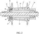
FIG. 2 is a sectional view of the first preferred embodiment of the present invention; -
FIG. 3 is an exploded view of the first preferred embodiment of the present invention; -
FIG. 4 is a perspective view of the first preferred embodiment of the present invention; -
FIG. 5 is a sketch diagram of the first ratchet device and the second ratchet device of the first preferred embodiment of the present invention; -
FIG. 6 is a sectional view of the first preferred embodiment of the present invention; -
FIG. 7 is a perspective view of the first preferred embodiment of the present invention; -
FIG. 8 is a sectional view of a second preferred embodiment of the present invention; and -
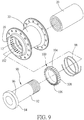
FIG. 9 is an exploded view of a third preferred embodiment of the present invention. - As shown in
FIGS. 1 and2 , a bicycle hub of the first preferred embodiment of the present invention includes ahousing 10 with achannel 12 therein. Thehousing 10 has afirst end 14 and asecond end 16 in an axial direction of thehousing 10. The first and thesecond ends housing 10 are on opposite open ends of thechannel 12. - The bicycle hub further includes a
driving device 20 next to thefirst end 14 of thehousing 10. Thedriving device 20 is connected to a transmission device, such as a belt or a chain, to transmit a torque. - As shown in
FIG. 3 andFIG. 4 , the present invention includes a unidirectional transmission apparatus, which is an inner ring type ratchet mechanism, including afirst ratchet device 40, asecond ratchet device 30, and a plurality ofelastic device 60. Thefirst ratchet device 40 has anaxle member 42 and aratchet member 44 connected to an end of theaxle member 42. Theratchet member 44 is provided with a plurality ofslots 46 on a circumference thereof. Thefirst ratchet device 40 is received in thechannel 12 of themember 10. Thesecond ratchet device 30 has a second ratchet portion. In the present embodiment, thesecond ratchet device 30 has aring member 34, and the second ratchet portion has ratchet teeth (32) on an inner side of thering member 34. Thering member 34 of thesecond ratchet device 30 is fixed to thehousing 10 and is adjacent to thesecond end 16 thereof. Theratchet member 44 of thefirst ratchet device 40 is received in thering member 34 of thesecond ratchet device 30 and thepaw slots 46 are associated with the ratchet teeth (32) of the second ratchet portion of thesecond ratchet device 30. - As shown in
FIG. 5 , thefirst ratchet device 40 further includes a first ratchet portion on theratchet member 44. In the present embodiment, the first ratchet portion includes a plurality ofpaws 48 received in theslots 46 respectively, and pivoted on theratchet member 44 of thefirst ratchet device 40. Theelastic devices 60, such as springs, are provided between sidewalls of theslots 46 and thepaws 48 respectively. Theelastic devices 60 urge thepaws 48 toward the ratchet teeth (32) of the second ratchet portion of thesecond ratchet device 30 respectively to engagepaws 48 with the ratchet teeth (32) of thesecond ratchet device 30. - As shown in
FIG. 2 , an end of theaxle member 42 of thefirst ratchet device 40, which is opposite to theratchet member 44 and faces thefirst end 14 of thehousing 10, is connected to thedriving device 20, so that thedriving device 20 is able to drive thefirst ratchet device 40 to rotate in a first direction or a second direction which is a reverse direction of the first direction. - As shown in
FIG. 6 , twoaxle bearings channel 12 of themember 10 and fitted to theaxle member 42 to make thefirst ratchet device 40 rotate freely in thechannel 12. - A
shaft 70 is received in thechannel 12 of thehousing 10 and passes through thefirst ratchet device 40 while twoshaft bearings shaft 70 and attached to thefirst ratchet device 40 to make thefirst ratchet device 40 rotate freely related to theshaft 70. - When the
driving device 20 drives thefirst ratchet device 40 to rotate in the first direction, thepaws 48 of the first ratchet portion of thefirst ratchet device 40 engage theratchet teeth 32 of the second ratchet portion of thesecond ratchet device 30 and thesecond ratchet device 30 is rotated with thefirst ratchet device 40. As a result, thehousing 10 is rotated. When thedriving device 20 drives thefirst ratchet device 40 to rotate in the second direction, thepaws 48 of the first ratchet portion of thefirst ratchet device 40 disengage the ratchet teeth (32) of the second ratchet portion of thesecond ratchet device 30 and thesecond ratchet device 30 is free. As a result, thehousing 10 stays still. - In the present preferred embodiment, the
driving device 20 includes a pulley as shown inFIG. 7 . The pulley is driven by a belt (not shown) and is screwed onto theaxle member 42 of the first ratchet device 40 (FIG. 6 ). - As shown in
FIG. 8 , the second preferred embodiment of the present invention provides thedriving device 20 including a freehub screwed onto theaxle member 42 of thefirst ratchet device 40. The freehub is connected to acassette 80. - As shown in
FIG. 9 . The third preferred embodiment of the present invention provides a unidirectional transmission apparatus, including afirst ratchet device 90 and asecond ratchet device 100. Thesecond ratchet device 100 has aring member 108 with a second ratchet portion, which hasratchet teeth 106 on an end of thering member 108. Thering member 108 of thesecond ratchet device 100 has second guidingmembers 104, which are protrusions on an outer side thereof, while thehousing 10 has first guidingmembers 102, which are slots on a sidewall of thechannel 12 of thehousing 10. Thesecond ratchet device 100 is received in thechannel 12 of thehousing 10 with thesecond guiding members 102 of thesecond ratchet device 100 engaging the first guidingmembers 104 of thehousing 10, so that thesecond ratchet device 100 is movable related to thehousing 10 and rotated with thehousing 10. Thefirst ratchet device 90 has anaxle member 92 and aratchet member 94 connected to an end of theaxle member 92. A diameter of theratchet member 94 is greater than that of theaxle member 92. Theratchet member 94 is provided with a first ratchet portion, which has ratchetteeth 96 on an end connected to theaxle member 92. Both thefirst ratchet device 90 and thesecond ratchet device 100 are received in thechannel 12 of thehousing 10, and theratchet teeth 96 of the first ratchet portion of thefirst ratchet device 90 face theratchet teeth 106 of the second ratchet portion of thesecond ratchet device 100. Anelastic device 98, such as a spring, is fitted to theaxle member 92 and urges thesecond ratchet device 100 toward theratchet member 94 of thefirst ratchet device 90 to engage theratchet teeth 96 of the first ratchet portion of thefirst ratchet device 90 with theratchet teeth 106 of thesecond ratchet device 100 when thefirst ratchet device 90 is rotated in the first direction. - With the combination of the
second ratchet device first ratchet device first ratchet device various driving device 20, such as pulley or freehub as described above or any other driving device, as the bicycle designer wants. In addition, the driving device and the unidirectional transmission apparatus are located at opposite sides of the housing, which provides a balanced torque transmission. The axle bearings, the shaft bearings, and the shaft are helpful to stabilize the rotation of the first ratchet device. - It must be pointed out that the embodiments described above are only some preferred embodiments of the present invention. All equivalent structures which employ the concepts disclosed in this specification and the appended claims should fall within the scope of the present invention.
Claims (8)
- A bicycle hub, comprising:a housing (10) having a first end (14) and a second end (16) opposite to the first end (14), wherein a channel (12) is formed in the housing (10) with opposite ends at the first end (14) and second end (16) respectively;a unidirectional transmission apparatus includes a first ratchet device (40 or 90), a second ratchet device (30 or 100), and an elastic device (60 or 98), wherein the first ratchet device (40 or 90) has an axle member (42 or 92) and a ratchet member (44 or 94) connected to an end of the axle member (42 or 92); the first ratchet device (40 or 90) is received in the channel (12) of the housing (10) with the ratchet member (44 or 94) adjacent to the second end (16) of the housing (10) and an end of the axle member (42 or 92), which is opposite to the ratchet member (44 or 94), adjacent to the first end (14) of the housing (10); the second ratchet device (30 or 100) is received in the channel (12) of the housing (10) and connected to the housing (10) to rotate with the housing (10); the second ratchet device (30 or 100) is adjacent to the second end (16) of the housing (10); the first ratchet device (40 or 90) has a first ratchet portion on the ratchet member (44 or 94), and the second ratchet device (30 or 100) has a second ratchet portion; the elastic device (60 or 98) urges one of the first ratchet portion of the first ratchet device (40 or 90) and the second ratchet portion of the second ratchet device (30 or 100); anda driving device (20) next to the first end (14) of the housing (10) and connected to the end of the axle member (42 or 92) of the first ratchet device (40 or 90) adjacent to the first end (14) of the housing (10) to drive the first ratchet device (40 or 90) to rotate in a first direction or a second direction which is a reverse direction of the first direction;wherein the first ratchet portion of the first ratchet device (40 or 90) engages the second ratchet portion of the second ratchet device (30 or 100) to rotate the housing (10) when the first ratchet device (40 or 90) is rotated in the first direction, and the first ratchet portion of the first ratchet device (40 or 90) disengages the second ratchet portion of the second ratchet device (30 or 100) when the first ratchet device (40 or 90) is rotated in the second direction.
- The bicycle hub of claim 1, wherein the first ratchet portion of the first ratchet device (40) has a paw (48) pivoted on the ratchet member (44); the second ratchet device (30) has a ring member (34), and the ring member (34) is fixed to the housing (10); the second ratchet portion has ratchet teeth (32) on an inner side of the ring member (34); the elastic device (60) urges the paw (48) toward the ratchet teeth (32) of the second ratchet device (30) to engage the paw (48) of the first ratchet device (40) with the ratchet teeth (32) of the second ratchet device (30).
- The bicycle hub of claim 2, wherein the ratchet member (44) of the first ratchet device (40) is provided with a slot (46), in which at least a portion of the paw (48) is received.
- The bicycle hub of claim 2, wherein the ratchet member (44) of the first ratchet device (40) is received in the ring member (34) of the second ratchet device (30).
- The bicycle hub of claim 1, wherein the first ratchet portion of the first ratchet device (90) has ratchet teeth (96) on an end of the ratchet member (94); the second ratchet portion of the second ratchet device (100) has ratchet teeth (106) facing the ratchet teeth (96) of the first ratchet portion of the first ratchet device (40); the elastic device (98) urges the second ratchet device (100) toward the ratchet member (94) of the first ratchet device (90) to engage the ratchet teeth (106) of the second ratchet portion of the second ratchet device (100) with the ratchet teeth (96) of the first ratchet portion of the first ratchet device (90).
- The bicycle hub of claim 5, wherein a diameter of the ratchet member (94) of the first ratchet device (90) is greater than that of the axle member (92) of the first ratchet device (90); the ratchet teeth (96) of the first ratchet portion of the first ratchet device (40) are provided on the end of the ratchet member (94) connected to the axle member (42); the second ratchet device (100) has a ring member (108) fitted to the axle member (92) of the first ratchet device (90); the elastic device (98) urges the ring member (108) of the second ratchet device (100) toward the ratchet member (94) of the first ratchet device (90) to engage the ratchet teeth (106) of the second ratchet portion of the second ratchet device (100) with the ratchet teeth (96) of the first ratchet portion of the first ratchet device (90).
- The bicycle hub of claim 5, wherein the housing (10) is provided with a first guiding member (102) on a sidewall of the channel (12), and the second ratchet device (100) is provided with a second guiding member (104); the second guiding member (104) of the second ratchet device (100) engages the first guiding member (102) of the housing (10) when the second ratchet device (100) is received in the channel (12) of the housing (10), so that the second ratchet device (100) is movable related to the housing (10) and rotated with the housing (10).
- The bicycle hub of claim 1, further comprising a shaft (70) and a shaft bearing (72 or 74), both of which are received in the channel (12) of the housing (10), wherein the shaft (70) passes through the first ratchet device (40), and the shaft bearing (72 or 74) is mounted between the first ratchet device (40) and the shaft (70).
Applications Claiming Priority (1)
| Application Number | Priority Date | Filing Date | Title |
|---|---|---|---|
| TW107136108A TWI669223B (en) | 2018-10-13 | 2018-10-13 | Hub structure with one way mechanism in reverse position |
Publications (1)
| Publication Number | Publication Date |
|---|---|
| EP3636450A1 true EP3636450A1 (en) | 2020-04-15 |
Family
ID=68290163
Family Applications (1)
| Application Number | Title | Priority Date | Filing Date |
|---|---|---|---|
| EP19202844.7A Withdrawn EP3636450A1 (en) | 2018-10-13 | 2019-10-11 | Bicycle hub having unidirectional transmission apparatus in opposite position |
Country Status (3)
| Country | Link |
|---|---|
| US (1) | US10960707B2 (en) |
| EP (1) | EP3636450A1 (en) |
| TW (1) | TWI669223B (en) |
Cited By (1)
| Publication number | Priority date | Publication date | Assignee | Title |
|---|---|---|---|---|
| WO2021038196A1 (en) * | 2019-08-23 | 2021-03-04 | Elkins Stephen Michael | Wheel hub |
Citations (3)
| Publication number | Priority date | Publication date | Assignee | Title |
|---|---|---|---|---|
| GB2127111A (en) * | 1982-07-09 | 1984-04-04 | Kimihiro Tsuchie | Cycle driving mechanism |
| EP1621788A1 (en) * | 2004-07-28 | 2006-02-01 | Rudolf Frei | Free-wheeling hub |
| CN106476533A (en) * | 2015-08-24 | 2017-03-08 | 骑记(厦门)科技有限公司 | Hub structure and bicycle |
Family Cites Families (10)
| Publication number | Priority date | Publication date | Assignee | Title |
|---|---|---|---|---|
| JPS62110003U (en) * | 1985-12-27 | 1987-07-14 | ||
| US5964332A (en) * | 1996-09-05 | 1999-10-12 | King; Christopher D. | Rear hub drive engagement mechanism |
| US6558288B2 (en) * | 2001-05-18 | 2003-05-06 | Shimano, Inc. | Internal transmission device with automatic shift mechanism for a bicycle |
| US8100810B2 (en) * | 2007-12-28 | 2012-01-24 | Shimano Inc. | Bicycle internal hub transmission with helical gear |
| US8336693B2 (en) * | 2009-10-27 | 2012-12-25 | Chun-Yi Wu | Bicycle hub |
| TW201221416A (en) * | 2010-11-22 | 2012-06-01 | Joy Ind Co Ltd | Bicycle hub structure with dual transmissions |
| JP2013047079A (en) * | 2011-08-29 | 2013-03-07 | Shimano Inc | Bicycle rear hub |
| US8443951B1 (en) * | 2011-11-18 | 2013-05-21 | Te-Yao HSIEH | Ratchet cylinder for a bicycle hub |
| TWM491588U (en) * | 2014-08-21 | 2014-12-11 | Foss Worldwide Inc | Locking and anti-tooth-loosening structure of bicycle hub |
| TWM537035U (en) * | 2016-10-14 | 2017-02-21 | Tian-Wang Hou | Bicycle clutch type hub |
-
2018
- 2018-10-13 TW TW107136108A patent/TWI669223B/en active
-
2019
- 2019-08-06 US US16/533,428 patent/US10960707B2/en not_active Expired - Fee Related
- 2019-10-11 EP EP19202844.7A patent/EP3636450A1/en not_active Withdrawn
Patent Citations (3)
| Publication number | Priority date | Publication date | Assignee | Title |
|---|---|---|---|---|
| GB2127111A (en) * | 1982-07-09 | 1984-04-04 | Kimihiro Tsuchie | Cycle driving mechanism |
| EP1621788A1 (en) * | 2004-07-28 | 2006-02-01 | Rudolf Frei | Free-wheeling hub |
| CN106476533A (en) * | 2015-08-24 | 2017-03-08 | 骑记(厦门)科技有限公司 | Hub structure and bicycle |
Cited By (2)
| Publication number | Priority date | Publication date | Assignee | Title |
|---|---|---|---|---|
| WO2021038196A1 (en) * | 2019-08-23 | 2021-03-04 | Elkins Stephen Michael | Wheel hub |
| US12157333B2 (en) | 2019-08-23 | 2024-12-03 | Stephen Michael ELKINS | Wheel hub |
Also Published As
| Publication number | Publication date |
|---|---|
| TW202014317A (en) | 2020-04-16 |
| US20200114684A1 (en) | 2020-04-16 |
| TWI669223B (en) | 2019-08-21 |
| US10960707B2 (en) | 2021-03-30 |
Similar Documents
| Publication | Publication Date | Title |
|---|---|---|
| US4220230A (en) | Overload release clutch | |
| US5407409A (en) | Exerciser with friction-type resistance device | |
| US20050130794A1 (en) | One-way clutch | |
| KR101911154B1 (en) | Torque limiter | |
| US8714527B2 (en) | Deceleration device | |
| US10960707B2 (en) | Bicycle hub having unidirectional transmission apparatus in opposite position | |
| US4530676A (en) | Adjustable-drive-ratio multiple-step belt transmission | |
| US20160045814A1 (en) | Rider Driven Skateboard | |
| AU2016203787B2 (en) | Linear Gear Shift Power Transfer Mechanism | |
| US20170074382A1 (en) | Ring clip assembly | |
| KR101537002B1 (en) | Reducer have trochoid gear | |
| KR102386791B1 (en) | One-way emission type power unit | |
| KR20160001344A (en) | Harmonic reducer | |
| US8015892B2 (en) | Bicycle clutch | |
| KR101082084B1 (en) | One-way ratchet clutch | |
| JP6600532B2 (en) | Pulley device | |
| KR200491507Y1 (en) | Reducer | |
| WO2017135046A1 (en) | Belt-type stepless transmission | |
| JP2021067286A (en) | Reverse input prevention clutch | |
| US9909654B2 (en) | Linear gear shift power transfer mechanism | |
| JP3219909U (en) | Decelerator | |
| EP3165792B1 (en) | Linear gear shift power transfer mechanism | |
| US20150027839A1 (en) | One-Way Clutch | |
| WO2017135047A1 (en) | Belt-type continuously variable transmission | |
| US6634586B1 (en) | Anti-reversional mechanism for trolling reel |
Legal Events
| Date | Code | Title | Description |
|---|---|---|---|
| PUAI | Public reference made under article 153(3) epc to a published international application that has entered the european phase |
Free format text: ORIGINAL CODE: 0009012 |
|
| STAA | Information on the status of an ep patent application or granted ep patent |
Free format text: STATUS: THE APPLICATION HAS BEEN PUBLISHED |
|
| AK | Designated contracting states |
Kind code of ref document: A1 Designated state(s): AL AT BE BG CH CY CZ DE DK EE ES FI FR GB GR HR HU IE IS IT LI LT LU LV MC MK MT NL NO PL PT RO RS SE SI SK SM TR |
|
| AX | Request for extension of the european patent |
Extension state: BA ME |
|
| STAA | Information on the status of an ep patent application or granted ep patent |
Free format text: STATUS: REQUEST FOR EXAMINATION WAS MADE |
|
| 17P | Request for examination filed |
Effective date: 20201014 |
|
| RBV | Designated contracting states (corrected) |
Designated state(s): AL AT BE BG CH CY CZ DE DK EE ES FI FR GB GR HR HU IE IS IT LI LT LU LV MC MK MT NL NO PL PT RO RS SE SI SK SM TR |
|
| STAA | Information on the status of an ep patent application or granted ep patent |
Free format text: STATUS: EXAMINATION IS IN PROGRESS |
|
| 17Q | First examination report despatched |
Effective date: 20220113 |
|
| STAA | Information on the status of an ep patent application or granted ep patent |
Free format text: STATUS: THE APPLICATION IS DEEMED TO BE WITHDRAWN |
|
| 18D | Application deemed to be withdrawn |
Effective date: 20220524 |