EP3636335A1 - Detoxifying device, method of replacing piping section of detoxifying device, and method of cleaning piping of detoxifying device - Google Patents
Detoxifying device, method of replacing piping section of detoxifying device, and method of cleaning piping of detoxifying device Download PDFInfo
- Publication number
- EP3636335A1 EP3636335A1 EP19202850.4A EP19202850A EP3636335A1 EP 3636335 A1 EP3636335 A1 EP 3636335A1 EP 19202850 A EP19202850 A EP 19202850A EP 3636335 A1 EP3636335 A1 EP 3636335A1
- Authority
- EP
- European Patent Office
- Prior art keywords
- piping
- detoxifying device
- stage
- cleaning water
- sprinkling
- Prior art date
- Legal status (The legal status is an assumption and is not a legal conclusion. Google has not performed a legal analysis and makes no representation as to the accuracy of the status listed.)
- Granted
Links
Images


Classifications
-
- B—PERFORMING OPERATIONS; TRANSPORTING
- B08—CLEANING
- B08B—CLEANING IN GENERAL; PREVENTION OF FOULING IN GENERAL
- B08B9/00—Cleaning hollow articles by methods or apparatus specially adapted thereto
- B08B9/02—Cleaning pipes or tubes or systems of pipes or tubes
- B08B9/027—Cleaning the internal surfaces; Removal of blockages
- B08B9/032—Cleaning the internal surfaces; Removal of blockages by the mechanical action of a moving fluid, e.g. by flushing
-
- B—PERFORMING OPERATIONS; TRANSPORTING
- B01—PHYSICAL OR CHEMICAL PROCESSES OR APPARATUS IN GENERAL
- B01D—SEPARATION
- B01D53/00—Separation of gases or vapours; Recovering vapours of volatile solvents from gases; Chemical or biological purification of waste gases, e.g. engine exhaust gases, smoke, fumes, flue gases, aerosols
- B01D53/34—Chemical or biological purification of waste gases
- B01D53/46—Removing components of defined structure
- B01D53/68—Halogens or halogen compounds
-
- H—ELECTRICITY
- H10—SEMICONDUCTOR DEVICES; ELECTRIC SOLID-STATE DEVICES NOT OTHERWISE PROVIDED FOR
- H10P—GENERIC PROCESSES OR APPARATUS FOR THE MANUFACTURE OR TREATMENT OF DEVICES COVERED BY CLASS H10
- H10P72/00—Handling or holding of wafers, substrates or devices during manufacture or treatment thereof
- H10P72/04—Apparatus for manufacture or treatment
-
- B—PERFORMING OPERATIONS; TRANSPORTING
- B01—PHYSICAL OR CHEMICAL PROCESSES OR APPARATUS IN GENERAL
- B01D—SEPARATION
- B01D47/00—Separating dispersed particles from gases, air or vapours by liquid as separating agent
- B01D47/06—Spray cleaning
-
- B—PERFORMING OPERATIONS; TRANSPORTING
- B01—PHYSICAL OR CHEMICAL PROCESSES OR APPARATUS IN GENERAL
- B01D—SEPARATION
- B01D53/00—Separation of gases or vapours; Recovering vapours of volatile solvents from gases; Chemical or biological purification of waste gases, e.g. engine exhaust gases, smoke, fumes, flue gases, aerosols
- B01D53/34—Chemical or biological purification of waste gases
- B01D53/346—Controlling the process
-
- B—PERFORMING OPERATIONS; TRANSPORTING
- B01—PHYSICAL OR CHEMICAL PROCESSES OR APPARATUS IN GENERAL
- B01D—SEPARATION
- B01D53/00—Separation of gases or vapours; Recovering vapours of volatile solvents from gases; Chemical or biological purification of waste gases, e.g. engine exhaust gases, smoke, fumes, flue gases, aerosols
- B01D53/34—Chemical or biological purification of waste gases
- B01D53/74—General processes for purification of waste gases; Apparatus or devices specially adapted therefor
- B01D53/77—Liquid phase processes
- B01D53/78—Liquid phase processes with gas-liquid contact
-
- B—PERFORMING OPERATIONS; TRANSPORTING
- B08—CLEANING
- B08B—CLEANING IN GENERAL; PREVENTION OF FOULING IN GENERAL
- B08B17/00—Methods preventing fouling
- B08B17/02—Preventing deposition of fouling or of dust
-
- B—PERFORMING OPERATIONS; TRANSPORTING
- B08—CLEANING
- B08B—CLEANING IN GENERAL; PREVENTION OF FOULING IN GENERAL
- B08B3/00—Cleaning by methods involving the use or presence of liquid or steam
- B08B3/04—Cleaning involving contact with liquid
- B08B3/10—Cleaning involving contact with liquid with additional treatment of the liquid or of the object being cleaned, e.g. by heat, by electricity or by vibration
-
- B—PERFORMING OPERATIONS; TRANSPORTING
- B08—CLEANING
- B08B—CLEANING IN GENERAL; PREVENTION OF FOULING IN GENERAL
- B08B9/00—Cleaning hollow articles by methods or apparatus specially adapted thereto
- B08B9/02—Cleaning pipes or tubes or systems of pipes or tubes
- B08B9/027—Cleaning the internal surfaces; Removal of blockages
- B08B9/032—Cleaning the internal surfaces; Removal of blockages by the mechanical action of a moving fluid, e.g. by flushing
- B08B9/0321—Cleaning the internal surfaces; Removal of blockages by the mechanical action of a moving fluid, e.g. by flushing using pressurised, pulsating or purging fluid
-
- C—CHEMISTRY; METALLURGY
- C23—COATING METALLIC MATERIAL; COATING MATERIAL WITH METALLIC MATERIAL; CHEMICAL SURFACE TREATMENT; DIFFUSION TREATMENT OF METALLIC MATERIAL; COATING BY VACUUM EVAPORATION, BY SPUTTERING, BY ION IMPLANTATION OR BY CHEMICAL VAPOUR DEPOSITION, IN GENERAL; INHIBITING CORROSION OF METALLIC MATERIAL OR INCRUSTATION IN GENERAL
- C23C—COATING METALLIC MATERIAL; COATING MATERIAL WITH METALLIC MATERIAL; SURFACE TREATMENT OF METALLIC MATERIAL BY DIFFUSION INTO THE SURFACE, BY CHEMICAL CONVERSION OR SUBSTITUTION; COATING BY VACUUM EVAPORATION, BY SPUTTERING, BY ION IMPLANTATION OR BY CHEMICAL VAPOUR DEPOSITION, IN GENERAL
- C23C16/00—Chemical coating by decomposition of gaseous compounds, without leaving reaction products of surface material in the coating, i.e. chemical vapour deposition [CVD] processes
- C23C16/44—Chemical coating by decomposition of gaseous compounds, without leaving reaction products of surface material in the coating, i.e. chemical vapour deposition [CVD] processes characterised by the method of coating
- C23C16/4401—Means for minimising impurities, e.g. dust, moisture or residual gas, in the reaction chamber
- C23C16/4407—Cleaning of reactor or reactor parts by using wet or mechanical methods
-
- C—CHEMISTRY; METALLURGY
- C23—COATING METALLIC MATERIAL; COATING MATERIAL WITH METALLIC MATERIAL; CHEMICAL SURFACE TREATMENT; DIFFUSION TREATMENT OF METALLIC MATERIAL; COATING BY VACUUM EVAPORATION, BY SPUTTERING, BY ION IMPLANTATION OR BY CHEMICAL VAPOUR DEPOSITION, IN GENERAL; INHIBITING CORROSION OF METALLIC MATERIAL OR INCRUSTATION IN GENERAL
- C23C—COATING METALLIC MATERIAL; COATING MATERIAL WITH METALLIC MATERIAL; SURFACE TREATMENT OF METALLIC MATERIAL BY DIFFUSION INTO THE SURFACE, BY CHEMICAL CONVERSION OR SUBSTITUTION; COATING BY VACUUM EVAPORATION, BY SPUTTERING, BY ION IMPLANTATION OR BY CHEMICAL VAPOUR DEPOSITION, IN GENERAL
- C23C16/00—Chemical coating by decomposition of gaseous compounds, without leaving reaction products of surface material in the coating, i.e. chemical vapour deposition [CVD] processes
- C23C16/44—Chemical coating by decomposition of gaseous compounds, without leaving reaction products of surface material in the coating, i.e. chemical vapour deposition [CVD] processes characterised by the method of coating
- C23C16/4412—Details relating to the exhausts, e.g. pumps, filters, scrubbers, particle traps
-
- B—PERFORMING OPERATIONS; TRANSPORTING
- B01—PHYSICAL OR CHEMICAL PROCESSES OR APPARATUS IN GENERAL
- B01D—SEPARATION
- B01D2252/00—Absorbents, i.e. solvents and liquid materials for gas absorption
- B01D2252/10—Inorganic absorbents
- B01D2252/103—Water
-
- B—PERFORMING OPERATIONS; TRANSPORTING
- B01—PHYSICAL OR CHEMICAL PROCESSES OR APPARATUS IN GENERAL
- B01D—SEPARATION
- B01D2257/00—Components to be removed
- B01D2257/20—Halogens or halogen compounds
- B01D2257/204—Inorganic halogen compounds
- B01D2257/2045—Hydrochloric acid
-
- B—PERFORMING OPERATIONS; TRANSPORTING
- B01—PHYSICAL OR CHEMICAL PROCESSES OR APPARATUS IN GENERAL
- B01D—SEPARATION
- B01D2257/00—Components to be removed
- B01D2257/20—Halogens or halogen compounds
- B01D2257/204—Inorganic halogen compounds
- B01D2257/2047—Hydrofluoric acid
-
- B—PERFORMING OPERATIONS; TRANSPORTING
- B01—PHYSICAL OR CHEMICAL PROCESSES OR APPARATUS IN GENERAL
- B01D—SEPARATION
- B01D2257/00—Components to be removed
- B01D2257/20—Halogens or halogen compounds
- B01D2257/206—Organic halogen compounds
- B01D2257/2066—Fluorine
-
- B—PERFORMING OPERATIONS; TRANSPORTING
- B01—PHYSICAL OR CHEMICAL PROCESSES OR APPARATUS IN GENERAL
- B01D—SEPARATION
- B01D2257/00—Components to be removed
- B01D2257/55—Compounds of silicon, phosphorus, germanium or arsenic
-
- B—PERFORMING OPERATIONS; TRANSPORTING
- B01—PHYSICAL OR CHEMICAL PROCESSES OR APPARATUS IN GENERAL
- B01D—SEPARATION
- B01D2257/00—Components to be removed
- B01D2257/55—Compounds of silicon, phosphorus, germanium or arsenic
- B01D2257/553—Compounds comprising hydrogen, e.g. silanes
-
- B—PERFORMING OPERATIONS; TRANSPORTING
- B01—PHYSICAL OR CHEMICAL PROCESSES OR APPARATUS IN GENERAL
- B01D—SEPARATION
- B01D2257/00—Components to be removed
- B01D2257/55—Compounds of silicon, phosphorus, germanium or arsenic
- B01D2257/556—Organic compounds
-
- B—PERFORMING OPERATIONS; TRANSPORTING
- B01—PHYSICAL OR CHEMICAL PROCESSES OR APPARATUS IN GENERAL
- B01D—SEPARATION
- B01D2258/00—Sources of waste gases
- B01D2258/02—Other waste gases
- B01D2258/0216—Other waste gases from CVD treatment or semi-conductor manufacturing
Definitions
- the present invention relates to a detoxifying device, a method of replacing a piping section of the detoxifying device, and a method of cleaning piping of the detoxifying device.
- a vacuum pump device has been widely used as one of facilities for manufacturing semiconductors, liquid crystals, solar panels, LEDs, and the like.
- a vacuum pump is connected to a vacuum chamber to discharge treatment gas in the vacuum chamber through evacuation.
- the treatment gas to be discharged through evacuation by the vacuum pump contains toxic combustible gas, for example, silane gas (SiH4), dichlorosilane gas (SiH 2 Cl 2 ), and ammonia (NH 3 ), or halogen hardly decomposable gas, for example, NF 3 , ClF 3 , SF 6 , CHF 3 , C 2 F 6 , CF 4 .
- toxic combustible gas for example, silane gas (SiH4), dichlorosilane gas (SiH 2 Cl 2 ), and ammonia (NH 3 ), or halogen hardly decomposable gas, for example, NF 3 , ClF 3 , SF 6 , CHF 3 , C 2 F 6 , CF 4 .
- a detoxifying device For the purpose of detoxifying the discharged treatment gas through evacuation, a detoxifying device is disposed in a subsequent stage of the vacuum pump.
- the process for detoxifying the treatment gas there have been known the wet process for removing the foreign substance and water-soluble component by bringing the treatment gas in contact with the liquid, and the combustion process for burning the treatment gas.
- a foreign substance removing mechanism may be disposed between the vacuum pump device and the detoxifying device for removing the foreign substance.
- a fan scrubber is known as one of the foreign substance removing mechanisms.
- the fan scrubber includes a fan that stirs the treatment gas, a motor for driving the fan, and a nozzle for injecting liquid.
- the fan scrubber serves to trap the foreign substance in the liquid injected from the nozzle.
- the fan scrubber functions as the wet detoxifying device as well as the foreign substance removing mechanism.
- the treatment gas may contain aluminum chloride (AlCl 3 ), ammonium chloride (NH 4 Cl), tetraethyl silicate (TEOS) and the like. Because of low steam pressure of the treatment gas at normal temperature, the solid product is generated from the treatment gas inside the piping of the detoxifying device at the lowering temperature. The resultant solid product may adhere to the wall surface of the piping to cause clogging of the piping. There may also be the case that the treatment gas contains BCl 3 used for etching Al wiring, or SiCl4 to be discharged upon etching of polysilicon using Cl based gas. The treatment gas as described above reacts with water to generate the solid product.
- AlCl 3 aluminum chloride
- NH 4 Cl ammonium chloride
- TEOS tetraethyl silicate
- Japanese Patent No. 4012818 discloses the exhaust gas treatment system as an example of the system provided with the detoxifying device with the function of removing the solid product in the piping.
- the disclosed exhaust gas treatment system includes the semiconductor manufacturing apparatus, the vacuum pump for discharging the gas (treatment gas) from the semiconductor manufacturing apparatus, a wet-type exhaust gas treatment device, a second pipe for connecting the vacuum pump and the wet-type exhaust gas treatment device, and a solid product removing device provided for the second pipe.
- the solid product removing device includes a tip opening formed in the second pipe, and a cleaning water introduction pipe for supplying the cleaning water from the tip opening to the inner surface of the second pipe.
- the solid product removing device is configured to wash out the solid product adhering to the inner surface of the second pipe as a result of reaction between the gas (treatment gas) and water content in the pipe using the cleaning water supplied from the tip opening.
- the disclosed exhaust gas treatment system is configured to remove the solid product adhering to the wall surface of the piping using the cleaning water.
- the wall surface of the piping is wet with the cleaning water while it is washed to remove the solid product. Meanwhile, when removal of the solid product is suspended, the wall surface of the piping is dried.
- the part of the wall surface in the piping through which the cleaning water flows, that is, the part adjacent to the tip opening for supplying the cleaning water is frequently subjected to the wet-dry cycle.
- a periphery of the tip opening for supplying the cleaning water is more likely to be corroded owing to the wet-dry cycle on the wall surface of the piping compared with the other part of the piping.
- the use of the detoxifying device in the corroded state may deteriorate the performance of the device, and cause failure of the entire device.
- the tip opening for supplying the cleaning water is formed in the inner surface of the second pipe, through which the cleaning water flows.
- the repetitive flow of the cleaning water through the tip opening may cause the risk of exfoliation of the coating from the rim of the tip opening.
- the exfoliation further leads to corrosion in the wall surface of the piping.
- the periphery of the opening for supplying the cleaning water whether it is PFA coated or not is likely to be corroded earlier than the other part of the piping.
- the detoxifying device has an inner wall that forms a flow passage through which the treatment gas flows.
- the detoxifying device includes a first piping, a replaceable piping section, and a second piping.
- the first piping forms a part of the flow passage.
- the piping section forms a part of the flow passage at a position downstream of the first piping, and is connected thereto.
- the piping section includes a first stage sprinkling portion for sprinkling a cleaning water to remove a solid product adhering to the inner wall.
- the second piping forms a part of the flow passage at a position downstream of the piping section, and is connected thereto.
- the method of replacing a piping section of the detoxifying device is implemented according to the present invention.
- the detoxifying device includes an inner wall that forms a flow passage through which treatment gas flows, a first piping that forms a part of the flow passage, a replaceable piping section that forms a part of the flow passage, is positioned downstream of the first piping and connected thereto, and includes a first stage sprinkling portion for sprinkling a cleaning water to remove a solid product adhering to the inner wall, and a second piping that forms a part of the flow passage, and is positioned downstream of the piping section and connected thereto.
- the method includes a step of replacing the piping section.
- the method of cleaning piping of the detoxifying device having an inner wall that forms a flow passage through which treatment gas flows is implemented according to the present invention.
- the detoxifying device includes a first stage sprinkling portion for sprinkling a cleaning water to remove a solid product adhering to the inner wall, a second stage sprinkling portion positioned upstream of the first stage sprinkling portion for sprinkling the cleaning water to remove the solid product adhering to the inner wall upstream of the first stage sprinkling portion, and a pressure sensor for measuring a pressure in the flow passage upstream of the first stage sprinkling portion.
- the method includes a step of sprinkling the cleaning water from the first stage sprinkling portion when the pressure sensor detects a pressure higher than a predetermined threshold value, and a step of sprinkling the cleaning water from the second stage sprinkling portion when the treatment gas that causes generation of the solid product stops flowing through the flow passage.
- Fig. 1 is a block diagram of a gas treatment system provided with a detoxifying device according to a first embodiment of the present invention.
- a gas treatment system 500 includes a manufacturing apparatus 501, a dry pump 502, a detoxifying device 100, a second detoxifying device 503, and an exhaust duct 504, all of which are connected with piping sequentially in the order.
- the dry pump 502 supplies the treatment gas drawn from the manufacturing apparatus 501 to the detoxifying device 100.
- Each of the detoxifying device 100 and the second detoxifying device 503 has a function of detoxifying the treatment gas.
- the exhaust duct 504 discharges the treatment gas flowing from the second detoxifying device 503.
- the gas treatment system 500 serves to detoxify and discharge the exhaust treatment gas from the manufacturing apparatus 501.
- the manufacturing apparatus 501 is electrically connected to the devices in the subsequent stage, that is, the dry pump 502, the detoxifying device 100, and the second detoxifying device 503.
- the detoxifying device 100 is electrically connected to the dry pump 502 and the second detoxifying device 503.
- the manufacturing apparatus 501, the detoxifying device 100, the dry pump 502, and the second detoxifying device 503 are electrically communicated with one another, and operated associatedly.
- Fig. 2 is a sectional view showing a structure of the detoxifying device 100.
- the detoxifying device 100 includes a fan scrubber 110, a first piping 130, a second piping 150, a piping section 170, and a spray 190.
- the detoxifying device 100 detoxifies the treatment gas drawn from a gas suction port 101, and discharges the detoxified treatment gas from a gas discharge port 102.
- the detoxifying device 100 may be employed in the facility of manufacturing, for example, for semiconductors, liquid crystals, solar panels, LEDs, and the like.
- the fan scrubber 110 includes a casing 111, a fan 112, a liquid supply passage 113, a nozzle 114, and a canned motor 15.
- the fan scrubber 110 has functions of trapping a foreign substance using the cleaning liquid injected from the nozzle 114, and bringing the treatment gas in contact with the cleaning liquid for detoxification.
- the casing 111 includes, for example, a piping connector 111a that draws in the treatment gas, a gas discharge port 111b that discharges the treatment gas, and a liquid discharge port 111c that discharges the cleaning liquid that has been used for detoxifying the treatment gas as waste liquid.
- the casing 111 covers the fan 112 to define the treatment gas passage.
- the fan 112 includes two opposing discs, and a plurality of blades disposed between the discs. The fan 112 turns around the center of the disc to stir the treatment gas in the casing 111.
- the liquid supply passage 113 extends from the piping connector 111a to a rotary shaft (main shaft 116 of the canned motor 115) of the fan 112, while having a part positioned adjacent to the second piping 150.
- the nozzle 114 is attached to an end of the liquid supply passage 113.
- the liquid supply passage 113 allows communication between a not shown pressure feed mechanism and the nozzle 114.
- the liquid supply passage 113 supplies the cleaning liquid fed from the pressure feed mechanism to the nozzle 114.
- the nozzle 114 includes a plurality of injection ports.
- the nozzle 114 is disposed to face the rotary shaft (the main shaft 116 of the canned motor 115) of the fan 112 therein.
- the nozzle 114 injects the cleaning liquid from the injection ports to the inside of the fan 112. Water, known liquid used for cleaning and the like may be used as the cleaning liquid.
- the canned motor 115 includes the main shaft 116, a rotor 117, a stator 118 disposed around an outer circumference of the rotor 117, a motor casing 119, and a can 120.
- the motor casing 119 houses the rotor 117 and the stator 118.
- the can 120 divides the inner space of the motor casing 119 into a rotor chamber in which the rotor 117 is disposed, and a stator chamber in which the stator 118 is disposed.
- the main shaft 116 of the canned motor 115 is connected to the fan 112. Accordingly, the fan 112 may be turned by rotation of the canned motor 115.
- the motor casing 119 and the casing 111 are directly connected.
- the detoxifying device 100 does not require the magnetic fluid seal to be disposed between the casing 111 and the canned motor 115 for preventing leakage of the treatment gas outside from the casing 111 and the canned motor 115. That is, as the detoxifying device 100 has no magnetic fluid seal, the leakage owing to the magnetic fluid seal never occurs. Although the treatment gas intrudes into the canned motor 115 from the inside of the casing 111 along the main shaft 116, the treatment gas does not come in contact with the stator 118 isolated by the can 120.
- the detoxifying device 100 is capable of preventing the treatment gas in the casing 111 from damaging the canned motor 115.
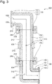
- Fig. 3 is an enlarged sectional view of a periphery of the first piping 130, the second piping 150, and the piping section 170 of the detoxifying device 100 as shown in Fig. 2 .
- an explanation will be made in more detail with respect to the first piping 130, the second piping 150, and the piping section 170.
- the detoxifying device 100 further includes a heater 210, an O-ring 230, and a clamp 250.
- the first piping 130, the second piping 150, and the piping section 170 integrally constitute the flow passage 103 through which the treatment gas flows.
- each of the first piping 130, the second piping 150, and the piping section 170 includes an inner wall 104 constituting the flow passage 103 through which the treatment gas flows.
- the vertically extending flow passage 103 has its upstream side located upper than its downstream side in the direction of gravity.
- the first piping 130 includes a pipe-like main body 131, and flanges 132 and 133 at both ends of the main body 131.
- the first piping 130 constitutes a part of the flow passage 103.
- the flange 132 is connected to a not shown device for discharging the treatment gas.
- the piping section 170 includes a pipe-like main body 171, and flanges 172 and 173 at both ends of the main body 171.
- the piping section 170 constitutes a part of the flow passage 103, and is positioned downstream of the first piping 130.
- a corrosion-resistant metal is used for forming the piping section 170.
- the use of the metal with relatively high corrosion resistance for the piping section 170 allows reduction in the frequency of required replacement of the piping section.
- the corrosion-resistant metal may be an inconel, SUS316, and the high corrosion-resistant metal used for forming the piping. The inconel exhibits higher corrosion resistance than the SUS316.
- the frequency of the required replacement of the piping section 170 may be reduced compared with the one formed of SUS316.
- the material cost of the piping section 170 becomes lower than the one formed of the inconel.
- the flange 172 of the piping section 170 and the flange 133 of the first piping 130 are fixed with the clamp 250.
- the O-ring 230 is attached to the joint between those flanges fixed with the clamp 250.
- the piping section 170 and the first piping 130 at the joint are tightly in contact with each other with the clamp 250, and further tightly sealed with the O-ring 230.
- the piping section 170 vertically extends (in the direction of gravity) as shown in Fig. 3 , for example.
- the upward direction of the piping section 170 is denoted as the upstream side, and the downward direction is denoted as the downstream side.
- the piping section 170 includes a sprinkling portion 174 (first stage sprinkling portion).
- the sprinkling portion 174 is a through hole positioned in the inner wall 104 of the pipe-like main body 171 while extending in the tangential direction of the inner wall 104.
- sprinkling portions 174 are formed in the circumferential direction of the inner wall 104 of the piping section 170 in a plane perpendicular to the longitudinal direction of the piping section 170 at equal intervals. In other words, the sprinkling portions 174 are formed in the circumference of the inner wall 104 of the piping section 170 at the same height in the vertical direction of Fig. 3 at equal intervals.
- a sealing ring 270 is fixed to an outer circumference of the piping section 170 while being wound therearound.
- the sealing ring 270 has a U-like cross section to form a cavity 105 between the sealing ring 270 and the outer circumference of the piping section 170.
- the cavity 105 covers the holes (sprinkling portions 174) of the piping section 170. That is, the cavity 105 to be formed by the sealing ring 270 is in communication with the holes (sprinkling portions 174).
- a cleaning water introduction pipe (not shown) for supplying the cleaning water is connected to the cavity 105.
- the sprinkling portion 174 sprinkles the cleaning water supplied to the cavity 105 from the cleaning water introduction pipe.
- the cleaning water sprinkled from the sprinkling portion 174 flows to the downstream of the flow passage 103 along the inner wall 104. This allows the cleaning water to wash out the solid product adhering to the inner wall 104.
- the sprinkling portion 174 sprinkles the cleaning water to allow the solid product adhering to the inner wall 104 to be removed.
- Water is used as the cleaning water, but a chemical solution for cleaning may also be used.
- the detoxifying device 100 has the sprinkling portion 174 as described above.
- the sprinkling portion 174 does not have to be structured as described above so long as the cleaning water can be sprinkled into the flow passage 103.
- the sprinkling portion 174 may be formed into a nozzle-like shape to be disposed inside the flow passage 103.
- the sprinkling portion 174 keeps blowing drying gas while sprinkling of the cleaning water is suspended. More specifically, the sprinkling portion 174 blows the drying gas for the fixed period from the end of sprinkling the cleaning water constantly at a first flow rate. After an elapse of the fixed period, the drying gas is blown at a second flow rate that is lower than the first flow rate.
- the drying gas inert gas, specifically, nitrogen may be used.
- the second piping 150 includes a pipe-like main body 151, and flanges 152 and 153 at both ends of the main body 151.
- a PFA coating 154 is applied to the inner wall 104 of the second piping 150. This makes it possible to restrain corrosion in the inner wall 104 of the second piping 150. This also prevents the solid product from adhering to the inner wall 104 of the second piping 150, and further prevents the cleaning water that has been flown from remaining on the inner wall 104 of the second piping 150.
- the second piping 150 constitutes a part of the flow passage 103 downstream of the piping section 170.
- the flange 152 of the second piping 150 and the flange 173 of the piping section 170 are fixed with the clamp 250.
- the O-ring 230 is attached to the joint between those flanges fixed with the clamp 250.
- the piping section 170 and the second piping 150 at the joint are tightly in contact with each other with the clamp 250, and further tightly sealed with the O-ring 230.
- the clamp 250 and the O-ring 230 allow the piping section 170 and the second piping 150 to be connected by a simple structure.
- the flange 153 is connected to the flange 121 (see Fig. 2 ) of the fan scrubber 110.
- the treatment gas drawn from the gas suction port 101 of the first piping 130 passes through the first piping 130, the piping section 170, and the second piping 150 sequentially to be supplied to the piping connector 111a of the fan scrubber 110 (see Fig. 2 ).
- the spray 190 is disposed in the flow passage 103 downstream of the sprinkling portion 174 to allow the sprinkling of the cleaning water toward the liquid supply passage 113 (see Fig. 2 ). More specifically, the spray 190 is disposed adjacent to the part of the inner wall 104, on which the cleaning water sprinkled from the sprinkling portion 174 flows. In the detoxifying device 100, the spray 190 is disposed inside the second piping 150, for example. The spray 190 sprinkles the cleaning water toward the liquid supply passage 113 to remove the solid product adhering thereto.
- the heater 210 is wound around the respective outer walls of the first piping 130, the second piping 150, and the piping section 170.
- the heater 210 heats the inner wall 104 to a predetermined temperature.
- the predetermined temperature is set in accordance with the treatment gas used for the treatment to be executed by the detoxifying device 100 to hinder generation of the solid product from the treatment gas. In other words, if the inner wall 104 is at the predetermined temperature, the solid product is unlikely to be generated on the inner wall 104.
- the detoxifying device 100 is configured to inject the cleaning liquid from the nozzle 114 of the fan scrubber 110 as mentioned above. As the cleaning liquid is supplied from the liquid supply passage 113, the temperature of the outer surface of the liquid supply passage 113 is lowered to make the solid product likely to adhere to the outer wall of the liquid supply passage 113. The cleaning water is sprinkled from the spray 190 to the outer surface of the liquid supply passage 113 to remove the solid product adhering to the outer wall of the liquid supply passage 113.
- the spray 190 sprinkles the cleaning water dispersedly.
- the cleaning water partially becomes droplets to adhere to a part of the inner wall 104 adjacent to the spray 190.
- the spray 190 sprinkles the cleaning water at high flow rate
- the sprinkled cleaning water will wash out the droplets of the cleaning water adhering to the inner wall 104. Therefore, on the part subjected to the sprinkled cleaning water at the high flow rate, the adhering droplets will be washed out before the solid product is grown into the substantially large size. As a result, the solid product generated from the treatment gas does not adhere to the inner wall.
- the treatment gas reacted with the droplets may generate the solid product (for example, the solid product 106 in Fig. 2 ) that is large enough to cause clogging of the flow passage.
- the detoxifying device 100 is provided with the sprinkling portion 174 upstream of the spray 190. Therefore, the cleaning water sprinkled from the sprinkling portion 174 vertically flows downward along the inner wall 104.
- the sprinkling portion 174 allows the cleaning water to flow on the part to which the solid product adheres so that the adhering solid product is removed.
- the time or time interval for sprinkling the cleaning water from the sprinkling portion 174 may be arbitrarily determined in accordance with the component of the treatment gas, and size or length of the flow passage.
- the sprinkling portion 174 blows the drying air at the first flow rate for a fixed period from the end of sprinkling the cleaning water. After an elapse of the fixed period, the sprinkling portion 174 blows the drying air at the second flow rate.
- the detoxifying device 100 allows the sprinkling portion 174 to blow the drying air at the first flow rate higher than the second flow rate at the end of sprinkling the cleaning water. This allows the inner wall 104 that has been wetted with the cleaning water to be quickly dried, and prevents the solid product as the cleaning water remaining on the inner wall 104 from newly adhering after introducing the cleaning water.
- the detoxifying device 100 allows the sprinkling portion 174 to blow the drying gas constantly to prevent intrusion of the treatment gas into the sprinkling portion 174.
- the heater 210 heats the inner wall 104 to be quickly dried.
- the part of the inner wall 104 adjacent to the sprinkling portion 174 is frequently subjected to the cycle of wetting with the sprinkled cleaning water and drying. This may cause the part to be corroded.
- the clamps 250 at both ends of the piping section 170 with the corroded part are removed. Then the piping section 170 with the corroded part is detached from the first piping 130 and the second piping 150. Thereafter, the non-corroded piping section 170 is interposed between the first piping 130 and the second piping 150, and fixed at both ends using the respective clamps 250.
- the detoxifying device 100 allows replacement of only the piping section 170 that is likely to be corroded.
- the detoxifying device 100 ensures to maintain the easily corrosible part adjacent to the sprinkling portion 174 in the non-corroded state by the replacement. That is, the detoxifying device 100 prevents performance deterioration of the device or failure of the entire device owing to corrosion in the inner wall 104 of the pipe.
- the detoxifying device 100 includes the fan scrubber 110 for treating the treatment gas.
- the detoxifying device 100 does not necessarily require the fan scrubber 110 so long as a mechanism for treating the treatment gas is provided.
- the heater 210 is wound around the outer walls of the first piping 130, the second piping 150, and the piping section 170 entirely.
- the heater 210 does not have to be wound around the entire outer wall, but may be disposed only to the part required to be heated.
- a detoxifying device has the same structure as that of the detoxifying device 100 according to the first embodiment except the piping section and a pressure sensor.
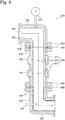
- Fig. 4 is an enlarged sectional view showing a periphery of the piping section of the detoxifying device according to the second embodiment of the present invention.
- a detoxifying device 300 of the second embodiment will be described in detail referring to Fig. 4 .
- the detoxifying device 300 includes a first piping 330, a second piping 350, a piping section 370, a heater 410, an O-ring 430, a clamp 450, a spray 390, and a pressure sensor 490.
- the first piping 330, the second piping 350, the heater 410, the O-ring 430, the clamp 450, and the spray 390 are the same as those described in the first embodiment.
- the piping section 370 is provided with all components constituting the piping section 170 as described in the first embodiment, and further includes a second stage sprinkling portion 375 upstream of a first stage sprinkling portion 374 (corresponding to the sprinkling portion 174 as described in the first embodiment).
- the second stage sprinkling portion 375 is a through hole positioned in an inner wall 304 of the pipe-like main body 371 while extending in the tangential direction of the inner wall 304.
- Four second stage sprinkling portions 375 are formed in the circumference direction of the inner wall 304 of the piping section 370 in a plane perpendicular to the longitudinal direction of the piping section 370 at equal intervals.
- the first stage sprinkling portions 374 are formed in the circumference of the inner wall 304 of the piping section 370 at the same height in the vertical direction of Fig. 4 at equal intervals.
- a sealing ring 470 is wound around the part of the second stage sprinkling portion 375 likewise the first stage sprinkling portion 374.
- the cleaning water may be sprinkled from the second stage sprinkling portion 375.
- the cleaning water sprinkled from the second stage sprinkling portion 375 flows to the downstream of the flow passage 303 along the inner wall 304.
- the second stage sprinkling portion 375 is positioned upstream of the first stage sprinkling portion 374.
- the second stage sprinkling portion 375 sprinkles the cleaning water to remove the solid product adhering to the inner wall 304 upstream of the first stage sprinkling portion 374.
- the second stage sprinkling portion 375 does not have to be structured similarly to the sprinkling portion 174 as described in the first embodiment so long as the cleaning water can be sprinkled into a flow passage 303.
- the detoxifying device 300 has the second stage sprinkling portions 375 included in the piping section 370. Although a part of the piping section 370 adjacent to the second stage sprinkling portion 375 is corroded thereby, the corroded part may be easily replaced by replacing the piping section 370.
- the pressure sensor 490 is disposed at the position which allows measurement of the internal pressure of the flow passage 303 upstream of the first stage sprinkling portion 374, and measures the pressure of the flow passage upstream of the first stage sprinkling portion 374.
- the detoxifying device 300 sets each timing of sprinkling the cleaning water from the first stage sprinkling portion 374 and the second stage sprinkling portion 375.
- the detoxifying device 300 includes a controller (not shown) that controls each timing of sprinkling the cleaning water from the first stage sprinkling portion 374 and the second stage sprinkling portion 375.
- the first stage sprinkling portion 374 sprinkles the cleaning water when the pressure sensor 490 measures the pressure higher than the predetermined threshold value.
- the second stage sprinkling portion 375 sprinkles the cleaning water when the treatment gas that causes generation of the solid product stops flowing through the flow passage 303.
- the detoxifying device 300 regards the timing when a process gas stop signal is received from the manufacturing apparatus 501 disposed in the prior stage of the detoxifying device 300 as the timing when the treatment gas that causes generation of the solid product stops flowing (see Fig. 1 ).
- the detoxifying device 300 may be configured to regard the timing when the process gas stop signal is received from the dry pump 502 disposed in the prior stage of the detoxifying device 300 or the second detoxifying device 503 disposed in the subsequent stage of the detoxifying device 300 as the timing when the treatment gas stops flowing (see Fig. 1 ).
- the detoxifying device 300 may also be configured to measure the wind speed in the flow passage 303, and regard the timing when the measured wind speed becomes equal to or lower than the fixed threshold value as the timing when the treatment gas that causes generation of the solid product stops flowing.
- the cleaning water sprinkled from the spray 390 may adhere to a part of the inner wall 304 of the second piping 350.
- the solid product may adhere to the part of the inner wall 304 of the second piping 350.
- the solid product adhering to the inner wall 304 grows larger with the passage of time, resulting in narrowing of the flow passage 303 through which the treatment gas flows. This makes it difficult for the treatment gas to flow, and increases the pressure in the flow passage upstream of the second piping 350 to which the solid product adheres.
- the pressure sensor 490 measures the increased pressure. When the pressure sensor 490 measures the pressure higher than the predetermined threshold value, the cleaning water is sprinkled from the first stage sprinkling portion 374.
- the first stage sprinkling portion 374 sprinkles the cleaning water. That is, the first stage sprinkling portion 374 is capable of removing the solid product by estimating the amount of the solid product adhering to the inner wall 304 based on the pressure. This ensures to prevent the solid product from causing clogging of the piping.
- the threshold value of the pressure, based on which the first stage sprinkling portion 374 starts sprinkling the cleaning water is arbitrarily determined in accordance with the flow rate required to allow the flow of the treatment gas.
- the cleaning water sprinkled from the first stage sprinkling portion 374 becomes droplets splashing around the first stage sprinkling portion 374.
- the splashed droplets of the cleaning water may adhere to the part upstream of the first stage sprinkling portion 374.
- the droplets adhering to the part upstream of the first stage sprinkling portion 374 react with the treatment gas to generate the solid product upstream of the first stage sprinkling portion 374.
- the resultant solid product is positioned upstream of the first stage sprinkling portion 374. It is therefore difficult to remove the solid product by sprinkling the cleaning water from the first stage sprinkling portion 374.
- the detoxifying device 300 includes the second stage sprinkling portion 375.
- the second stage sprinkling portion 375 sprinkles the cleaning water to remove the solid product adjacent to the first stage sprinkling portion 374 downstream of the second stage sprinkling portion 375. That is, the detoxifying device 300 allows the second stage sprinkling portion 375 to remove the solid product that has adhered by sprinkling the cleaning water from the first stage sprinkling portion 374.
- the second stage sprinkling portion 375 sprinkles the cleaning water when the treatment gas that causes generation of the solid product stops flowing through the flow passage 303.
- the treatment gas stops flowing through the flow passage 303 upon suspension of supplying the treatment gas from the device disposed in the prior stage of the detoxifying device 300. That is, the detoxifying device 300 is capable of removing the solid product that has adhered by sprinkling the cleaning water from the second stage sprinkling portion 375 upon suspension of supplying the treatment gas from the device in the prior stage.
- the device for supplying the treatment gas stops supplying the treatment gas at the end of executing the predetermined process.
- the detoxifying device 300 is capable of removing the solid product regularly at the end of the predetermined process executed by the device in the prior stage. As described above, the detoxifying device 300 regards the timing when receiving the process gas stop signal from the manufacturing apparatus 501 disposed in the prior stage of the detoxifying device 300 as the timing when the treatment gas that causes generation of the solid product stops flowing. The solid product adhering by sprinkling the cleaning water from the first stage sprinkling portion 374 may be removed regularly when the dry pump 502 disposed in the prior stage stops supplying the treatment gas.
- the dry pump 502 supplies the treatment gas to the detoxifying device 300.
- the treatment gas flows through the flow passage 303 while reacting with water to generate the solid product on the inner wall 304.
- the pressure detected by the pressure sensor 490 is increased.
- the first stage sprinkling portion 374 sprinkles the cleaning water.
- the first stage sprinkling portion 374 ensures to prevent the solid product from causing clogging of the part of the piping downstream of the first stage sprinkling portion 374.
- the manufacturing apparatus 501 transmits the process gas stop signal to the detoxifying device 300.
- the detoxifying device 300 regards the reception of the process gas stop signal as the timing when the treatment gas that causes generation of the solid product stops flowing.
- the second sprinkling portion 375 sprinkles the cleaning water.
- the detoxifying device 300 is capable of removing the solid product that has adhered by sprinkling the cleaning water from the first stage sprinkling portion 374 regularly at the end of the predetermined process executed by the manufacturing apparatus 501.
- the second sprinkling portion 375 starts sprinkling the cleaning water when the treatment gas that causes generation of the solid product stops flowing through the flow passage 303.
- the timing for starting sprinkling the cleaning water by the second stage sprinkling portion 375 may be arbitrarily determined in a non-restricted manner.
- the second stage sprinkling portion 375 is allowed to start sprinkling the cleaning water when receiving the predetermined signal from the device in the prior stage.
- the device in the prior stage of the detoxifying device 300 is the semiconductor manufacturing apparatus, it is possible to set the sprinkling start timing in synchronization with the end of the deposition process.
- the deposition process refers to the process for depositing impurities at predetermined concentration to the silicon surface.
- the detoxifying device 300 is capable of removing the solid product at the end of executing the deposition process.
- the detoxifying device has the inner wall that forms the flow passage through which the treatment gas flows.
- the detoxifying device includes a first piping, a replaceable piping section, and a second piping.
- the first piping forms a part of the flow passage.
- the piping section forms a part of the flow passage at a position downstream of the first piping, and is connected thereto.
- the piping section includes a first stage sprinkling portion for sprinkling a cleaning water to remove a solid product adhering to the inner wall.
- the second piping forms a part of the flow passage at a position downstream of the piping section, and is connected thereto.
- the first stage sprinkling portion is included in the replaceable piping section.
- corrosion occurs in the part adjacent to the first stage sprinkling portion resulting from removing the solid product adhering to the inner wall, the corroded part may be easily replaced by replacing the piping section. This allows the wall surface of the piping to be kept in the non-corroded state.
- the detoxifying device is capable of restraining performance deterioration of the device or failure of the entire device owing to the corrosion in the wall surface of the piping.
- a detoxifying device is the detoxifying device according to Embodiment 1, further including a heater for heating the inner wall.
- the detoxifying device according to Embodiment 2 allows the heater to heat the inner wall to restrain adhesion of the solid product to the inner wall.
- a detoxifying device is the detoxifying device according to Embodiment 1 or 2, wherein the piping section is made of a corrosion-resistant metal.
- the use of the metal with relatively high corrosion resistance for the piping section allows reduction in the frequency of required replacement of the piping section.
- a detoxifying device is the detoxifying device according to any one of Embodiments 1 to 3, wherein a PFA coating is applied to the inner wall corresponding to the second piping.
- the PFA coating is applied to the part on the inner wall of the second piping for restraining corrosion in the inner wall of the second piping.
- a detoxifying device is the detoxifying device according to any one of Embodiments 1 to 4, further including an O-ring that tightly seals a joint between the piping section and the first or the second piping, and a clamp that brings the piping section in tight contact with the first or the second piping at the joint.
- the piping section is connected to the first or the second piping with a simple structure using the O-ring and the clamps.
- the piping section may be easily detached by removing the clamps.
- the newly provided piping section after the replacement may be easily fixed with the clamps.
- a detoxifying device is the detoxifying device according to any one of Embodiments 1 to 5, further including a second stage sprinkling portion positioned upstream of the first stage sprinkling portion for sprinkling the cleaning water to remove the solid product adhering to the inner wall upstream of the first stage sprinkling portion.
- the cleaning water sprinkled from the first stage sprinkling portion splashes to possibly generate the solid product in the part upstream of the first stage sprinkling portion.
- the use of the second stage sprinkling portion may remove the solid product that has adhered by sprinkling the cleaning water from the first stage sprinkling portion.
- a detoxifying device is the detoxifying device according to Embodiment 6, further including a pressure sensor for measuring a pressure in the flow passage upstream of the first stage sprinkling portion.
- the first stage sprinkling portion sprinkles the cleaning water when the pressure sensor detects a pressure higher than a predetermined threshold value.
- the second stage sprinkling portion sprinkles the cleaning water when the treatment gas that causes generation of the solid product stops flowing through the flow passage.
- the detoxifying device allows the pressure sensor to measure the pressure increase in the flow passage, and further allows the first stage sprinkling portion to remove the solid product as needed. Since the second stage sprinkling portion sprinkles the cleaning water when the treatment gas that causes generation of the solid product stops flowing through the flow passage, the detoxifying device is capable of removing the solid product that has adhered by sprinkling the cleaning water from the first stage sprinkling portion regularly at the end of the predetermined process executed by the device in the prior stage.
- a detoxifying device is the detoxifying device according to Embodiment 7, wherein the second stage sprinkling portion sprinkles the cleaning water in accordance with a timing when receiving a process gas stop signal from a device disposed in a prior stage or a subsequent stage of the detoxifying device.
- the timing is regarded as a timing when the treatment gas that causes generation of the solid product stops flowing.
- the detoxifying device regards the timing when receiving the process gas stop signal output from the device in the prior stage of the detoxifying device, or the process gas stop signal from the device in the subsequent stage of the detoxifying device as the timing when the treatment gas that causes generation of the solid product stops flowing.
- the detoxifying device is capable of removing the solid product adhering by sprinkling the cleaning water from the first stage sprinkling portion regularly when the device in the prior stage stops supplying the treatment gas.
- a detoxifying device is the detoxifying device according to any one of Embodiments 6 to 8, wherein the second stage sprinkling portion is included in the piping section.
- the second stage sprinkling portion is included in the piping section.
- the corrosion that occurs in the part adjacent to the second stage sprinkling portion the corroded part may be easily replaced.
- a detoxifying device is the detoxifying device according to any one of Embodiments 1 to 9, wherein the first stage detoxifying portion keeps blowing drying gas when sprinkling of the cleaning water is suspended.
- the first stage sprinkling portion blows the drying gas. This makes it possible to prevent the treatment gas from intruding into the first stage sprinkling portion when sprinkling of the cleaning water is suspended.
- a detoxifying device is the detoxifying device according to Embodiment 10, wherein the drying gas is blown at a first flow rate constantly for a fixed period from the end of sprinkling the cleaning water, and after an elapse of the fixed period, the drying gas is blown at a second flow rate that is lower than the first flow rate.
- the flow rate of the drying gas blown from the first stage sprinkling portion for the fixed period from the end of sprinkling the cleaning water is higher than the flow rate of the drying gas blown from the first stage sprinkling portion after an elapse of the fixed period.
- the detoxifying device is capable of quickly dries the wall surface that has been wetted with the cleaning water.
- a detoxifying device according to Embodiment 12 is the detoxifying device according to Embodiment 10 or 11, wherein inert gas is used as the drying gas.
- the detoxifying device allows the use of easily available inactive gas as the drying gas.
- a detoxifying device is the detoxifying device according to any one of Embodiments 1 to 12, further including a fan scrubber having a liquid supply passage for supplying the cleaning liquid, and a spray positioned downstream of the first stage sprinkling portion for sprinkling the cleaning water to remove the solid product adhering to the liquid supply passage.
- the cleaning water sprinkled from the spray toward the liquid supply passage removes the solid product adhering to the liquid supply passage in the stream of the cleaning water.
- the cleaning water partially becomes droplets to adhere to a part on the inner wall adjacent to the spray.
- the treatment gas reacts with the droplets remaining on the part where the cleaning water flows at the low flow rate.
- the treatment gas reacted with the droplets may generate the solid product that will grow larger to cause clogging of the flow passage.
- the detoxifying device according to the present Embodiment 13 includes the first stage sprinkling portion upstream of the spray. This allows the detoxifying device to remove the solid product generated owing to the spray using the cleaning water sprinkled from the first stage sprinkling portion.
- a detoxifying device is the detoxifying device according to Embodiment 13, wherein the fan scrubber includes a fan and a canned motor for rotating the fan.
- the canned motor is used as the motor for rotating the fan of the fan scrubber.
- the canned motor is hardly brought into the failure caused by intrusion of the cleaning water into the canned motor.
- the detoxifying device includes an inner wall that forms a flow passage through which treatment gas flows, a first piping that forms a part of the flow passage, a replaceable piping section that forms a part of the flow passage at a position downstream of the first piping, is connected thereto, and includes a first stage sprinkling portion for sprinkling a cleaning water to remove a solid product adhering to the inner wall, and a second piping that forms a part of the flow passage at a position downstream of the piping section, and is connected thereto.
- the method includes a step of replacing the piping section.
- the corroded part may be easily replaced by replacing the piping section. This allows the wall surface of the piping to be kept in the non-corroded state. It is therefore possible to restrain performance deterioration of the device or failure of the entire device owing to the corrosion in the wall surface of the piping.
- the detoxifying device having an inner wall that forms a flow passage through which treatment gas flows includes a first stage sprinkling portion for sprinkling a cleaning water to remove a solid product adhering to the inner wall, a second stage sprinkling portion positioned upstream of the first stage sprinkling portion for sprinkling the cleaning water to remove the solid product adhering to the inner wall upstream of the first stage sprinkling portion, and a pressure sensor for measuring a pressure in the flow passage upstream of the first stage sprinkling portion.
- the method includes a step of sprinkling the cleaning water from the first stage sprinkling portion when the pressure sensor detects a pressure higher than a predetermined threshold value, and a step of sprinkling the cleaning water from the second stage sprinkling portion when the treatment gas that causes generation of the solid product stops flowing through the flow passage.
- the first stage sprinkling portion ensures to prevent the solid product from causing clogging of the piping downstream of the first stage sprinkling portion.
- the second stage sprinkling portion sprinkles the cleaning water when the treatment gas that causes generation of the solid product stops flowing through the flow passage.
- the detoxifying device is capable of removing the solid product that has adhered by sprinkling of the cleaning water from the first stage sprinkling portion regularly at the end of the predetermined process executed by the device in the prior stage of the detoxifying device.
Landscapes
- Chemical & Material Sciences (AREA)
- Engineering & Computer Science (AREA)
- Chemical Kinetics & Catalysis (AREA)
- Mechanical Engineering (AREA)
- General Chemical & Material Sciences (AREA)
- Environmental & Geological Engineering (AREA)
- Oil, Petroleum & Natural Gas (AREA)
- Analytical Chemistry (AREA)
- Biomedical Technology (AREA)
- Health & Medical Sciences (AREA)
- Materials Engineering (AREA)
- Metallurgy (AREA)
- Organic Chemistry (AREA)
- Treating Waste Gases (AREA)
- Cleaning In General (AREA)
- Cleaning By Liquid Or Steam (AREA)
- Gas Separation By Absorption (AREA)
- Catching Or Destruction (AREA)
Abstract
Description
- The present invention relates to a detoxifying device, a method of replacing a piping section of the detoxifying device, and a method of cleaning piping of the detoxifying device.
- A vacuum pump device has been widely used as one of facilities for manufacturing semiconductors, liquid crystals, solar panels, LEDs, and the like. In the process for manufacturing those products, a vacuum pump is connected to a vacuum chamber to discharge treatment gas in the vacuum chamber through evacuation. The treatment gas to be discharged through evacuation by the vacuum pump contains toxic combustible gas, for example, silane gas (SiH4), dichlorosilane gas (SiH2Cl2), and ammonia (NH3), or halogen hardly decomposable gas, for example, NF3, ClF3, SF6, CHF3, C2F6, CF4. The above-described treatment gas through evacuation by the vacuum pump cannot be discharged to the atmosphere as it is. For the purpose of detoxifying the discharged treatment gas through evacuation, a detoxifying device is disposed in a subsequent stage of the vacuum pump. As the process for detoxifying the treatment gas, there have been known the wet process for removing the foreign substance and water-soluble component by bringing the treatment gas in contact with the liquid, and the combustion process for burning the treatment gas.
- There may be the case that the substance solidified as a result of the reaction in the vacuum chamber or an easily solidifiable substance as the reaction by-product is mixedly contained in the treatment gas to be discharged from the vacuum pump. Those substances intruding into the detoxifying device may cause clogging of the piping and the detoxifying device, or deteriorate treatment efficiency of the detoxifying device. A foreign substance removing mechanism may be disposed between the vacuum pump device and the detoxifying device for removing the foreign substance.
- A fan scrubber is known as one of the foreign substance removing mechanisms. The fan scrubber includes a fan that stirs the treatment gas, a motor for driving the fan, and a nozzle for injecting liquid. The fan scrubber serves to trap the foreign substance in the liquid injected from the nozzle. The fan scrubber functions as the wet detoxifying device as well as the foreign substance removing mechanism.
- The treatment gas may contain aluminum chloride (AlCl3), ammonium chloride (NH4Cl), tetraethyl silicate (TEOS) and the like. Because of low steam pressure of the treatment gas at normal temperature, the solid product is generated from the treatment gas inside the piping of the detoxifying device at the lowering temperature. The resultant solid product may adhere to the wall surface of the piping to cause clogging of the piping. There may also be the case that the treatment gas contains BCl3 used for etching Al wiring, or SiCl4 to be discharged upon etching of polysilicon using Cl based gas. The treatment gas as described above reacts with water to generate the solid product. If the inside of the detoxifying device is wet, the resultant solid product may cause clogging of the piping. It is therefore necessary to remove the solid product adhering to the wall surface of the piping. There has been a known detoxifying device having the function of removing the solid product adhering to the wall surface of the piping.
- For example, Japanese Patent No.
4012818 - The disclosed exhaust gas treatment system is configured to remove the solid product adhering to the wall surface of the piping using the cleaning water. The wall surface of the piping is wet with the cleaning water while it is washed to remove the solid product. Meanwhile, when removal of the solid product is suspended, the wall surface of the piping is dried. The part of the wall surface in the piping through which the cleaning water flows, that is, the part adjacent to the tip opening for supplying the cleaning water is frequently subjected to the wet-dry cycle. A periphery of the tip opening for supplying the cleaning water is more likely to be corroded owing to the wet-dry cycle on the wall surface of the piping compared with the other part of the piping. The use of the detoxifying device in the corroded state may deteriorate the performance of the device, and cause failure of the entire device.
- If the PFA coating is applied to the part of the wall surface of the piping frequently subjected to the wet-dry cycle, the corrosion in the coated part is expected to be restrained. The tip opening for supplying the cleaning water is formed in the inner surface of the second pipe, through which the cleaning water flows. The repetitive flow of the cleaning water through the tip opening may cause the risk of exfoliation of the coating from the rim of the tip opening. The exfoliation further leads to corrosion in the wall surface of the piping. The periphery of the opening for supplying the cleaning water whether it is PFA coated or not is likely to be corroded earlier than the other part of the piping.
- It is an object of the present invention to provide a detoxifying device capable of restraining performance deterioration of the device and failure of the entire device resulting from the corrosion in the wall surface of piping, a method of replacing the piping section of the detoxifying device, and a method of cleaning piping of the detoxifying device.
- The detoxifying device according to the present invention has an inner wall that forms a flow passage through which the treatment gas flows. The detoxifying device includes a first piping, a replaceable piping section, and a second piping. The first piping forms a part of the flow passage. The piping section forms a part of the flow passage at a position downstream of the first piping, and is connected thereto. The piping section includes a first stage sprinkling portion for sprinkling a cleaning water to remove a solid product adhering to the inner wall. The second piping forms a part of the flow passage at a position downstream of the piping section, and is connected thereto.
- The method of replacing a piping section of the detoxifying device is implemented according to the present invention. The detoxifying device includes an inner wall that forms a flow passage through which treatment gas flows, a first piping that forms a part of the flow passage, a replaceable piping section that forms a part of the flow passage, is positioned downstream of the first piping and connected thereto, and includes a first stage sprinkling portion for sprinkling a cleaning water to remove a solid product adhering to the inner wall, and a second piping that forms a part of the flow passage, and is positioned downstream of the piping section and connected thereto. The method includes a step of replacing the piping section.
- The method of cleaning piping of the detoxifying device having an inner wall that forms a flow passage through which treatment gas flows is implemented according to the present invention. The detoxifying device includes a first stage sprinkling portion for sprinkling a cleaning water to remove a solid product adhering to the inner wall, a second stage sprinkling portion positioned upstream of the first stage sprinkling portion for sprinkling the cleaning water to remove the solid product adhering to the inner wall upstream of the first stage sprinkling portion, and a pressure sensor for measuring a pressure in the flow passage upstream of the first stage sprinkling portion. The method includes a step of sprinkling the cleaning water from the first stage sprinkling portion when the pressure sensor detects a pressure higher than a predetermined threshold value, and a step of sprinkling the cleaning water from the second stage sprinkling portion when the treatment gas that causes generation of the solid product stops flowing through the flow passage.
-
Fig. 1 is a block diagram of a gas treatment system provided with a detoxifying device according to a first embodiment of the present invention; -
Fig. 2 is a sectional view showing a structure of the detoxifying device according to the first embodiment of the present invention; -
Fig. 3 is an enlarged sectional view showing a periphery of a first piping, a second piping, and a piping section of the detoxifying device as shown inFig. 2 ; and -
Fig. 4 is an enlarged sectional view showing a periphery of a piping section of a detoxifying device according to a second embodiment of the present invention. - Embodiments of the present invention will be described referring to the drawings. The same or corresponding components are denoted as the same reference signs in the drawings, and repetitive explanations thereof, thus will be omitted.
-
Fig. 1 is a block diagram of a gas treatment system provided with a detoxifying device according to a first embodiment of the present invention. Referring toFig. 1 , agas treatment system 500 includes amanufacturing apparatus 501, adry pump 502, a detoxifyingdevice 100, a second detoxifyingdevice 503, and anexhaust duct 504, all of which are connected with piping sequentially in the order. - When the
manufacturing apparatus 501 is operated to execute the predetermined process, thedry pump 502 supplies the treatment gas drawn from themanufacturing apparatus 501 to the detoxifyingdevice 100. Each of the detoxifyingdevice 100 and the second detoxifyingdevice 503 has a function of detoxifying the treatment gas. Theexhaust duct 504 discharges the treatment gas flowing from the second detoxifyingdevice 503. Thegas treatment system 500 serves to detoxify and discharge the exhaust treatment gas from themanufacturing apparatus 501. - The
manufacturing apparatus 501 is electrically connected to the devices in the subsequent stage, that is, thedry pump 502, thedetoxifying device 100, and the second detoxifyingdevice 503. The detoxifyingdevice 100 is electrically connected to thedry pump 502 and the second detoxifyingdevice 503. In thegas treatment system 500, themanufacturing apparatus 501, thedetoxifying device 100, thedry pump 502, and thesecond detoxifying device 503 are electrically communicated with one another, and operated associatedly. -
Fig. 2 is a sectional view showing a structure of thedetoxifying device 100. Referring toFig. 2 , thedetoxifying device 100 includes afan scrubber 110, afirst piping 130, asecond piping 150, apiping section 170, and aspray 190. Thedetoxifying device 100 detoxifies the treatment gas drawn from agas suction port 101, and discharges the detoxified treatment gas from agas discharge port 102. Thedetoxifying device 100 may be employed in the facility of manufacturing, for example, for semiconductors, liquid crystals, solar panels, LEDs, and the like. - Components of the
detoxifying device 100 will be described. - The
fan scrubber 110 includes acasing 111, afan 112, aliquid supply passage 113, anozzle 114, and a canned motor 15. Thefan scrubber 110 has functions of trapping a foreign substance using the cleaning liquid injected from thenozzle 114, and bringing the treatment gas in contact with the cleaning liquid for detoxification. - The
casing 111 includes, for example, apiping connector 111a that draws in the treatment gas, agas discharge port 111b that discharges the treatment gas, and aliquid discharge port 111c that discharges the cleaning liquid that has been used for detoxifying the treatment gas as waste liquid. Thecasing 111 covers thefan 112 to define the treatment gas passage. - The
fan 112 includes two opposing discs, and a plurality of blades disposed between the discs. Thefan 112 turns around the center of the disc to stir the treatment gas in thecasing 111. - The
liquid supply passage 113 extends from thepiping connector 111a to a rotary shaft (main shaft 116 of the canned motor 115) of thefan 112, while having a part positioned adjacent to thesecond piping 150. Thenozzle 114 is attached to an end of theliquid supply passage 113. Theliquid supply passage 113 allows communication between a not shown pressure feed mechanism and thenozzle 114. Theliquid supply passage 113 supplies the cleaning liquid fed from the pressure feed mechanism to thenozzle 114. - The
nozzle 114 includes a plurality of injection ports. Thenozzle 114 is disposed to face the rotary shaft (themain shaft 116 of the canned motor 115) of thefan 112 therein. Thenozzle 114 injects the cleaning liquid from the injection ports to the inside of thefan 112. Water, known liquid used for cleaning and the like may be used as the cleaning liquid. - The
canned motor 115 includes themain shaft 116, arotor 117, astator 118 disposed around an outer circumference of therotor 117, amotor casing 119, and acan 120. Themotor casing 119 houses therotor 117 and thestator 118. The can 120 divides the inner space of themotor casing 119 into a rotor chamber in which therotor 117 is disposed, and a stator chamber in which thestator 118 is disposed. Themain shaft 116 of the cannedmotor 115 is connected to thefan 112. Accordingly, thefan 112 may be turned by rotation of the cannedmotor 115. Themotor casing 119 and thecasing 111 are directly connected. Accordingly, thedetoxifying device 100 does not require the magnetic fluid seal to be disposed between thecasing 111 and thecanned motor 115 for preventing leakage of the treatment gas outside from thecasing 111 and thecanned motor 115. That is, as thedetoxifying device 100 has no magnetic fluid seal, the leakage owing to the magnetic fluid seal never occurs. Although the treatment gas intrudes into thecanned motor 115 from the inside of thecasing 111 along themain shaft 116, the treatment gas does not come in contact with thestator 118 isolated by thecan 120. Thedetoxifying device 100 is capable of preventing the treatment gas in thecasing 111 from damaging thecanned motor 115. -
Fig. 3 is an enlarged sectional view of a periphery of thefirst piping 130, thesecond piping 150, and thepiping section 170 of thedetoxifying device 100 as shown inFig. 2 . Referring toFig. 3 , an explanation will be made in more detail with respect to thefirst piping 130, thesecond piping 150, and thepiping section 170. - As
Fig. 3 shows, thedetoxifying device 100 further includes aheater 210, an O-ring 230, and aclamp 250. - The
first piping 130, thesecond piping 150, and thepiping section 170 integrally constitute theflow passage 103 through which the treatment gas flows. In other words, each of thefirst piping 130, thesecond piping 150, and thepiping section 170 includes aninner wall 104 constituting theflow passage 103 through which the treatment gas flows. The vertically extendingflow passage 103 has its upstream side located upper than its downstream side in the direction of gravity. - The
first piping 130 includes a pipe-like main body 131, andflanges first piping 130 constitutes a part of theflow passage 103. Theflange 132 is connected to a not shown device for discharging the treatment gas. - The
piping section 170 includes a pipe-likemain body 171, andflanges main body 171. Thepiping section 170 constitutes a part of theflow passage 103, and is positioned downstream of thefirst piping 130. A corrosion-resistant metal is used for forming thepiping section 170. The use of the metal with relatively high corrosion resistance for thepiping section 170 allows reduction in the frequency of required replacement of the piping section. The corrosion-resistant metal may be an inconel, SUS316, and the high corrosion-resistant metal used for forming the piping. The inconel exhibits higher corrosion resistance than the SUS316. If thepiping section 170 is formed of the inconel, the frequency of the required replacement of thepiping section 170 may be reduced compared with the one formed of SUS316. On the contrary, if thepiping section 170 is formed of SUS316, the material cost of thepiping section 170 becomes lower than the one formed of the inconel. Theflange 172 of thepiping section 170 and theflange 133 of thefirst piping 130 are fixed with theclamp 250. The O-ring 230 is attached to the joint between those flanges fixed with theclamp 250. Thepiping section 170 and thefirst piping 130 at the joint are tightly in contact with each other with theclamp 250, and further tightly sealed with the O-ring 230. Thepiping section 170 vertically extends (in the direction of gravity) as shown inFig. 3 , for example. The upward direction of thepiping section 170 is denoted as the upstream side, and the downward direction is denoted as the downstream side. Thepiping section 170 includes a sprinkling portion 174 (first stage sprinkling portion). For example, the sprinklingportion 174 is a through hole positioned in theinner wall 104 of the pipe-likemain body 171 while extending in the tangential direction of theinner wall 104. Four sprinklingportions 174 are formed in the circumferential direction of theinner wall 104 of thepiping section 170 in a plane perpendicular to the longitudinal direction of thepiping section 170 at equal intervals. In other words, the sprinklingportions 174 are formed in the circumference of theinner wall 104 of thepiping section 170 at the same height in the vertical direction ofFig. 3 at equal intervals. A sealingring 270 is fixed to an outer circumference of thepiping section 170 while being wound therearound. The sealingring 270 has a U-like cross section to form a cavity 105 between the sealingring 270 and the outer circumference of thepiping section 170. The cavity 105 covers the holes (sprinkling portions 174) of thepiping section 170. That is, the cavity 105 to be formed by the sealingring 270 is in communication with the holes (sprinkling portions 174). A cleaning water introduction pipe (not shown) for supplying the cleaning water is connected to the cavity 105. The sprinklingportion 174 sprinkles the cleaning water supplied to the cavity 105 from the cleaning water introduction pipe. The cleaning water sprinkled from the sprinklingportion 174 flows to the downstream of theflow passage 103 along theinner wall 104. This allows the cleaning water to wash out the solid product adhering to theinner wall 104. In other words, the sprinklingportion 174 sprinkles the cleaning water to allow the solid product adhering to theinner wall 104 to be removed. Water is used as the cleaning water, but a chemical solution for cleaning may also be used. Thedetoxifying device 100 has the sprinklingportion 174 as described above. However, the sprinklingportion 174 does not have to be structured as described above so long as the cleaning water can be sprinkled into theflow passage 103. For example, the sprinklingportion 174 may be formed into a nozzle-like shape to be disposed inside theflow passage 103. - The sprinkling
portion 174 keeps blowing drying gas while sprinkling of the cleaning water is suspended. More specifically, the sprinklingportion 174 blows the drying gas for the fixed period from the end of sprinkling the cleaning water constantly at a first flow rate. After an elapse of the fixed period, the drying gas is blown at a second flow rate that is lower than the first flow rate. As the drying gas, inert gas, specifically, nitrogen may be used. - The
second piping 150 includes a pipe-likemain body 151, andflanges main body 151. APFA coating 154 is applied to theinner wall 104 of thesecond piping 150. This makes it possible to restrain corrosion in theinner wall 104 of thesecond piping 150. This also prevents the solid product from adhering to theinner wall 104 of thesecond piping 150, and further prevents the cleaning water that has been flown from remaining on theinner wall 104 of thesecond piping 150. Thesecond piping 150 constitutes a part of theflow passage 103 downstream of thepiping section 170. Theflange 152 of thesecond piping 150 and theflange 173 of thepiping section 170 are fixed with theclamp 250. The O-ring 230 is attached to the joint between those flanges fixed with theclamp 250. Thepiping section 170 and thesecond piping 150 at the joint are tightly in contact with each other with theclamp 250, and further tightly sealed with the O-ring 230. Theclamp 250 and the O-ring 230 allow thepiping section 170 and thesecond piping 150 to be connected by a simple structure. Theflange 153 is connected to the flange 121 (seeFig. 2 ) of thefan scrubber 110. - In the above-structured
detoxifying device 100, the treatment gas drawn from thegas suction port 101 of thefirst piping 130 passes through thefirst piping 130, thepiping section 170, and thesecond piping 150 sequentially to be supplied to thepiping connector 111a of the fan scrubber 110 (seeFig. 2 ). - The
spray 190 is disposed in theflow passage 103 downstream of the sprinklingportion 174 to allow the sprinkling of the cleaning water toward the liquid supply passage 113 (seeFig. 2 ). More specifically, thespray 190 is disposed adjacent to the part of theinner wall 104, on which the cleaning water sprinkled from the sprinklingportion 174 flows. In thedetoxifying device 100, thespray 190 is disposed inside thesecond piping 150, for example. Thespray 190 sprinkles the cleaning water toward theliquid supply passage 113 to remove the solid product adhering thereto. - The
heater 210 is wound around the respective outer walls of thefirst piping 130, thesecond piping 150, and thepiping section 170. Theheater 210 heats theinner wall 104 to a predetermined temperature. The predetermined temperature is set in accordance with the treatment gas used for the treatment to be executed by thedetoxifying device 100 to hinder generation of the solid product from the treatment gas. In other words, if theinner wall 104 is at the predetermined temperature, the solid product is unlikely to be generated on theinner wall 104. - An operation for removing the solid product in the
detoxifying device 100 will be described again referring toFig. 2 . - The
detoxifying device 100 is configured to inject the cleaning liquid from thenozzle 114 of thefan scrubber 110 as mentioned above. As the cleaning liquid is supplied from theliquid supply passage 113, the temperature of the outer surface of theliquid supply passage 113 is lowered to make the solid product likely to adhere to the outer wall of theliquid supply passage 113. The cleaning water is sprinkled from thespray 190 to the outer surface of theliquid supply passage 113 to remove the solid product adhering to the outer wall of theliquid supply passage 113. - The
spray 190 sprinkles the cleaning water dispersedly. The cleaning water partially becomes droplets to adhere to a part of theinner wall 104 adjacent to thespray 190. On the part where thespray 190 sprinkles the cleaning water at high flow rate, the sprinkled cleaning water will wash out the droplets of the cleaning water adhering to theinner wall 104. Therefore, on the part subjected to the sprinkled cleaning water at the high flow rate, the adhering droplets will be washed out before the solid product is grown into the substantially large size. As a result, the solid product generated from the treatment gas does not adhere to the inner wall. Meanwhile, on the part where the cleaning water sprinkled from thespray 190 flows at the low flow rate, the droplets of the cleaning water adhering to theinner wall 104 cannot be washed out sufficiently. On the above-described part where the cleaning water sprinkled from thespray 190 flows at the low flow rate, the treatment gas reacted with the droplets may generate the solid product (for example, thesolid product 106 inFig. 2 ) that is large enough to cause clogging of the flow passage. Thedetoxifying device 100 is provided with the sprinklingportion 174 upstream of thespray 190. Therefore, the cleaning water sprinkled from the sprinklingportion 174 vertically flows downward along theinner wall 104. The sprinklingportion 174 allows the cleaning water to flow on the part to which the solid product adheres so that the adhering solid product is removed. The time or time interval for sprinkling the cleaning water from the sprinklingportion 174 may be arbitrarily determined in accordance with the component of the treatment gas, and size or length of the flow passage. - The sprinkling
portion 174 blows the drying air at the first flow rate for a fixed period from the end of sprinkling the cleaning water. After an elapse of the fixed period, the sprinklingportion 174 blows the drying air at the second flow rate. Thedetoxifying device 100 allows the sprinklingportion 174 to blow the drying air at the first flow rate higher than the second flow rate at the end of sprinkling the cleaning water. This allows theinner wall 104 that has been wetted with the cleaning water to be quickly dried, and prevents the solid product as the cleaning water remaining on theinner wall 104 from newly adhering after introducing the cleaning water. When sprinkling of the cleaning water from the sprinklingportion 174 is suspended, thedetoxifying device 100 allows the sprinklingportion 174 to blow the drying gas constantly to prevent intrusion of the treatment gas into the sprinklingportion 174. Theheater 210 heats theinner wall 104 to be quickly dried. - A method of replacing the
piping section 170 will be described referring toFig. 3 . - As described above, in the
detoxifying device 100, because of sprinkling taking place from the sprinklingportion 174, the part of theinner wall 104 adjacent to the sprinklingportion 174 is frequently subjected to the cycle of wetting with the sprinkled cleaning water and drying. This may cause the part to be corroded. - If the part of the
inner wall 104 adjacent to the sprinklingportion 174 is corroded, theclamps 250 at both ends of thepiping section 170 with the corroded part are removed. Then thepiping section 170 with the corroded part is detached from thefirst piping 130 and thesecond piping 150. Thereafter, thenon-corroded piping section 170 is interposed between thefirst piping 130 and thesecond piping 150, and fixed at both ends using therespective clamps 250. - The
detoxifying device 100 allows replacement of only thepiping section 170 that is likely to be corroded. Thedetoxifying device 100 ensures to maintain the easily corrosible part adjacent to the sprinklingportion 174 in the non-corroded state by the replacement. That is, thedetoxifying device 100 prevents performance deterioration of the device or failure of the entire device owing to corrosion in theinner wall 104 of the pipe. - In the present embodiment, the
detoxifying device 100 includes thefan scrubber 110 for treating the treatment gas. However, thedetoxifying device 100 does not necessarily require thefan scrubber 110 so long as a mechanism for treating the treatment gas is provided. - In the
detoxifying device 100, theheater 210 is wound around the outer walls of thefirst piping 130, thesecond piping 150, and thepiping section 170 entirely. Theheater 210 does not have to be wound around the entire outer wall, but may be disposed only to the part required to be heated. - A detoxifying device according to a second embodiment of the present invention has the same structure as that of the
detoxifying device 100 according to the first embodiment except the piping section and a pressure sensor. -
Fig. 4 is an enlarged sectional view showing a periphery of the piping section of the detoxifying device according to the second embodiment of the present invention. Adetoxifying device 300 of the second embodiment will be described in detail referring toFig. 4 . - The
detoxifying device 300 includes afirst piping 330, asecond piping 350, apiping section 370, aheater 410, an O-ring 430, aclamp 450, aspray 390, and apressure sensor 490. Thefirst piping 330, thesecond piping 350, theheater 410, the O-ring 430, theclamp 450, and thespray 390 are the same as those described in the first embodiment. - The
piping section 370 is provided with all components constituting thepiping section 170 as described in the first embodiment, and further includes a secondstage sprinkling portion 375 upstream of a first stage sprinkling portion 374 (corresponding to the sprinklingportion 174 as described in the first embodiment). - Likewise the first
stage sprinkling portion 374, the secondstage sprinkling portion 375 is a through hole positioned in aninner wall 304 of the pipe-likemain body 371 while extending in the tangential direction of theinner wall 304. Four secondstage sprinkling portions 375 are formed in the circumference direction of theinner wall 304 of thepiping section 370 in a plane perpendicular to the longitudinal direction of thepiping section 370 at equal intervals. In other words, the firststage sprinkling portions 374 are formed in the circumference of theinner wall 304 of thepiping section 370 at the same height in the vertical direction ofFig. 4 at equal intervals. A sealingring 470 is wound around the part of the secondstage sprinkling portion 375 likewise the firststage sprinkling portion 374. The cleaning water may be sprinkled from the secondstage sprinkling portion 375. The cleaning water sprinkled from the secondstage sprinkling portion 375 flows to the downstream of theflow passage 303 along theinner wall 304. The secondstage sprinkling portion 375 is positioned upstream of the firststage sprinkling portion 374. The secondstage sprinkling portion 375 sprinkles the cleaning water to remove the solid product adhering to theinner wall 304 upstream of the firststage sprinkling portion 374. The secondstage sprinkling portion 375 does not have to be structured similarly to the sprinklingportion 174 as described in the first embodiment so long as the cleaning water can be sprinkled into aflow passage 303. - As described above, the
detoxifying device 300 has the secondstage sprinkling portions 375 included in thepiping section 370. Although a part of thepiping section 370 adjacent to the secondstage sprinkling portion 375 is corroded thereby, the corroded part may be easily replaced by replacing thepiping section 370. - The
pressure sensor 490 is disposed at the position which allows measurement of the internal pressure of theflow passage 303 upstream of the firststage sprinkling portion 374, and measures the pressure of the flow passage upstream of the firststage sprinkling portion 374. - The
detoxifying device 300 sets each timing of sprinkling the cleaning water from the firststage sprinkling portion 374 and the secondstage sprinkling portion 375. Thedetoxifying device 300 includes a controller (not shown) that controls each timing of sprinkling the cleaning water from the firststage sprinkling portion 374 and the secondstage sprinkling portion 375. Specifically, the firststage sprinkling portion 374 sprinkles the cleaning water when thepressure sensor 490 measures the pressure higher than the predetermined threshold value. Meanwhile, the secondstage sprinkling portion 375 sprinkles the cleaning water when the treatment gas that causes generation of the solid product stops flowing through theflow passage 303. Thedetoxifying device 300 regards the timing when a process gas stop signal is received from themanufacturing apparatus 501 disposed in the prior stage of thedetoxifying device 300 as the timing when the treatment gas that causes generation of the solid product stops flowing (seeFig. 1 ). Thedetoxifying device 300 may be configured to regard the timing when the process gas stop signal is received from thedry pump 502 disposed in the prior stage of thedetoxifying device 300 or thesecond detoxifying device 503 disposed in the subsequent stage of thedetoxifying device 300 as the timing when the treatment gas stops flowing (seeFig. 1 ). Thedetoxifying device 300 may also be configured to measure the wind speed in theflow passage 303, and regard the timing when the measured wind speed becomes equal to or lower than the fixed threshold value as the timing when the treatment gas that causes generation of the solid product stops flowing. - An operation of the
detoxifying device 300 for removing the solid product will be described. - Likewise the
detoxifying device 100, in thedetoxifying device 300, the cleaning water sprinkled from thespray 390 may adhere to a part of theinner wall 304 of thesecond piping 350. As a result, the solid product may adhere to the part of theinner wall 304 of thesecond piping 350. The solid product adhering to theinner wall 304 grows larger with the passage of time, resulting in narrowing of theflow passage 303 through which the treatment gas flows. This makes it difficult for the treatment gas to flow, and increases the pressure in the flow passage upstream of thesecond piping 350 to which the solid product adheres. Thepressure sensor 490 measures the increased pressure. When thepressure sensor 490 measures the pressure higher than the predetermined threshold value, the cleaning water is sprinkled from the firststage sprinkling portion 374. At the timing when a certain amount of the solid product has adhered to theinner wall 304, the firststage sprinkling portion 374 sprinkles the cleaning water. That is, the firststage sprinkling portion 374 is capable of removing the solid product by estimating the amount of the solid product adhering to theinner wall 304 based on the pressure. This ensures to prevent the solid product from causing clogging of the piping. The threshold value of the pressure, based on which the firststage sprinkling portion 374 starts sprinkling the cleaning water is arbitrarily determined in accordance with the flow rate required to allow the flow of the treatment gas. - The cleaning water sprinkled from the first
stage sprinkling portion 374 becomes droplets splashing around the firststage sprinkling portion 374. The splashed droplets of the cleaning water may adhere to the part upstream of the firststage sprinkling portion 374. The droplets adhering to the part upstream of the firststage sprinkling portion 374 react with the treatment gas to generate the solid product upstream of the firststage sprinkling portion 374. The resultant solid product is positioned upstream of the firststage sprinkling portion 374. It is therefore difficult to remove the solid product by sprinkling the cleaning water from the firststage sprinkling portion 374. In the present embodiment, thedetoxifying device 300 includes the secondstage sprinkling portion 375. The secondstage sprinkling portion 375 sprinkles the cleaning water to remove the solid product adjacent to the firststage sprinkling portion 374 downstream of the secondstage sprinkling portion 375. That is, thedetoxifying device 300 allows the secondstage sprinkling portion 375 to remove the solid product that has adhered by sprinkling the cleaning water from the firststage sprinkling portion 374. - In the
detoxifying device 300, the secondstage sprinkling portion 375 sprinkles the cleaning water when the treatment gas that causes generation of the solid product stops flowing through theflow passage 303. The treatment gas stops flowing through theflow passage 303 upon suspension of supplying the treatment gas from the device disposed in the prior stage of thedetoxifying device 300. That is, thedetoxifying device 300 is capable of removing the solid product that has adhered by sprinkling the cleaning water from the secondstage sprinkling portion 375 upon suspension of supplying the treatment gas from the device in the prior stage. Generally, the device for supplying the treatment gas stops supplying the treatment gas at the end of executing the predetermined process. Thedetoxifying device 300 is capable of removing the solid product regularly at the end of the predetermined process executed by the device in the prior stage. As described above, thedetoxifying device 300 regards the timing when receiving the process gas stop signal from themanufacturing apparatus 501 disposed in the prior stage of thedetoxifying device 300 as the timing when the treatment gas that causes generation of the solid product stops flowing. The solid product adhering by sprinkling the cleaning water from the firststage sprinkling portion 374 may be removed regularly when thedry pump 502 disposed in the prior stage stops supplying the treatment gas. - The method of cleaning the piping of the
detoxifying device 300 will be described. - When the
manufacturing apparatus 501 in the prior stage of thedetoxifying device 300 executes the predetermined process, thedry pump 502 supplies the treatment gas to thedetoxifying device 300. The treatment gas flows through theflow passage 303 while reacting with water to generate the solid product on theinner wall 304. As a result, the pressure detected by thepressure sensor 490 is increased. When thepressure sensor 490 detects the pressure higher than the predetermined threshold value, the firststage sprinkling portion 374 sprinkles the cleaning water. The firststage sprinkling portion 374 ensures to prevent the solid product from causing clogging of the part of the piping downstream of the firststage sprinkling portion 374. At the end of the predetermined process executed by themanufacturing apparatus 501, themanufacturing apparatus 501 transmits the process gas stop signal to thedetoxifying device 300. Thedetoxifying device 300 regards the reception of the process gas stop signal as the timing when the treatment gas that causes generation of the solid product stops flowing. Then thesecond sprinkling portion 375 sprinkles the cleaning water. Thedetoxifying device 300 is capable of removing the solid product that has adhered by sprinkling the cleaning water from the firststage sprinkling portion 374 regularly at the end of the predetermined process executed by themanufacturing apparatus 501. - In the
detoxifying device 300, thesecond sprinkling portion 375 starts sprinkling the cleaning water when the treatment gas that causes generation of the solid product stops flowing through theflow passage 303. The timing for starting sprinkling the cleaning water by the secondstage sprinkling portion 375 may be arbitrarily determined in a non-restricted manner. For example, the secondstage sprinkling portion 375 is allowed to start sprinkling the cleaning water when receiving the predetermined signal from the device in the prior stage. Specifically, assuming that the device in the prior stage of thedetoxifying device 300 is the semiconductor manufacturing apparatus, it is possible to set the sprinkling start timing in synchronization with the end of the deposition process. The deposition process refers to the process for depositing impurities at predetermined concentration to the silicon surface. Thedetoxifying device 300 is capable of removing the solid product at the end of executing the deposition process. - The above-described embodiments may be configured as described below partially or entirely in a non-restricted manner.
- The detoxifying device according to Embodiment 1 has the inner wall that forms the flow passage through which the treatment gas flows. The detoxifying device includes a first piping, a replaceable piping section, and a second piping. The first piping forms a part of the flow passage. The piping section forms a part of the flow passage at a position downstream of the first piping, and is connected thereto. The piping section includes a first stage sprinkling portion for sprinkling a cleaning water to remove a solid product adhering to the inner wall. The second piping forms a part of the flow passage at a position downstream of the piping section, and is connected thereto.
- In the detoxifying device according to Embodiment 1, the first stage sprinkling portion is included in the replaceable piping section. Although corrosion occurs in the part adjacent to the first stage sprinkling portion resulting from removing the solid product adhering to the inner wall, the corroded part may be easily replaced by replacing the piping section. This allows the wall surface of the piping to be kept in the non-corroded state. The detoxifying device is capable of restraining performance deterioration of the device or failure of the entire device owing to the corrosion in the wall surface of the piping.
- A detoxifying device according to Embodiment 2 is the detoxifying device according to Embodiment 1, further including a heater for heating the inner wall.
- The detoxifying device according to Embodiment 2 allows the heater to heat the inner wall to restrain adhesion of the solid product to the inner wall.
- A detoxifying device according to Embodiment 3 is the detoxifying device according to Embodiment 1 or 2, wherein the piping section is made of a corrosion-resistant metal.
- In the detoxifying device according to Embodiment 3, the use of the metal with relatively high corrosion resistance for the piping section allows reduction in the frequency of required replacement of the piping section.
- A detoxifying device according to Embodiment 4 is the detoxifying device according to any one of Embodiments 1 to 3, wherein a PFA coating is applied to the inner wall corresponding to the second piping.
- In the detoxifying device according to Embodiment 4, the PFA coating is applied to the part on the inner wall of the second piping for restraining corrosion in the inner wall of the second piping.
- A detoxifying device according to Embodiment 5 is the detoxifying device according to any one of Embodiments 1 to 4, further including an O-ring that tightly seals a joint between the piping section and the first or the second piping, and a clamp that brings the piping section in tight contact with the first or the second piping at the joint.
- In the detoxifying device according to Embodiment 5, the piping section is connected to the first or the second piping with a simple structure using the O-ring and the clamps. The piping section may be easily detached by removing the clamps. The newly provided piping section after the replacement may be easily fixed with the clamps.
- A detoxifying device according to Embodiment 6 is the detoxifying device according to any one of Embodiments 1 to 5, further including a second stage sprinkling portion positioned upstream of the first stage sprinkling portion for sprinkling the cleaning water to remove the solid product adhering to the inner wall upstream of the first stage sprinkling portion.
- In the detoxifying device, the cleaning water sprinkled from the first stage sprinkling portion splashes to possibly generate the solid product in the part upstream of the first stage sprinkling portion. In the detoxifying device according to Embodiment 6, the use of the second stage sprinkling portion may remove the solid product that has adhered by sprinkling the cleaning water from the first stage sprinkling portion.
- A detoxifying device according to Embodiment 7 is the detoxifying device according to Embodiment 6, further including a pressure sensor for measuring a pressure in the flow passage upstream of the first stage sprinkling portion. The first stage sprinkling portion sprinkles the cleaning water when the pressure sensor detects a pressure higher than a predetermined threshold value. The second stage sprinkling portion sprinkles the cleaning water when the treatment gas that causes generation of the solid product stops flowing through the flow passage.
- When the width of the flow passage through which the treatment gas flows in the piping is narrowed by the solid product adhering to the wall surface of the piping in the detoxifying device, the pressure in the flow passage increases. The detoxifying device according to Embodiment 7, allows the pressure sensor to measure the pressure increase in the flow passage, and further allows the first stage sprinkling portion to remove the solid product as needed. Since the second stage sprinkling portion sprinkles the cleaning water when the treatment gas that causes generation of the solid product stops flowing through the flow passage, the detoxifying device is capable of removing the solid product that has adhered by sprinkling the cleaning water from the first stage sprinkling portion regularly at the end of the predetermined process executed by the device in the prior stage.
- A detoxifying device according to Embodiment 8 is the detoxifying device according to Embodiment 7, wherein the second stage sprinkling portion sprinkles the cleaning water in accordance with a timing when receiving a process gas stop signal from a device disposed in a prior stage or a subsequent stage of the detoxifying device. The timing is regarded as a timing when the treatment gas that causes generation of the solid product stops flowing.
- The detoxifying device according to Embodiment 8 regards the timing when receiving the process gas stop signal output from the device in the prior stage of the detoxifying device, or the process gas stop signal from the device in the subsequent stage of the detoxifying device as the timing when the treatment gas that causes generation of the solid product stops flowing. The detoxifying device is capable of removing the solid product adhering by sprinkling the cleaning water from the first stage sprinkling portion regularly when the device in the prior stage stops supplying the treatment gas.
- A detoxifying device according to Embodiment 9 is the detoxifying device according to any one of Embodiments 6 to 8, wherein the second stage sprinkling portion is included in the piping section.
- In the detoxifying device according to Embodiment 8, the second stage sprinkling portion is included in the piping section. In the case of the corrosion that occurs in the part adjacent to the second stage sprinkling portion, the corroded part may be easily replaced.
- A detoxifying device according to Embodiment 10 is the detoxifying device according to any one of Embodiments 1 to 9, wherein the first stage detoxifying portion keeps blowing drying gas when sprinkling of the cleaning water is suspended.
- In the detoxifying device according to Embodiment 10, the first stage sprinkling portion blows the drying gas. This makes it possible to prevent the treatment gas from intruding into the first stage sprinkling portion when sprinkling of the cleaning water is suspended.
- A detoxifying device according to Embodiment 11 is the detoxifying device according to Embodiment 10, wherein the drying gas is blown at a first flow rate constantly for a fixed period from the end of sprinkling the cleaning water, and after an elapse of the fixed period, the drying gas is blown at a second flow rate that is lower than the first flow rate.
- In detoxifying device according to Embodiment 11, the flow rate of the drying gas blown from the first stage sprinkling portion for the fixed period from the end of sprinkling the cleaning water is higher than the flow rate of the drying gas blown from the first stage sprinkling portion after an elapse of the fixed period. As a result, at the end of sprinkling, the detoxifying device is capable of quickly dries the wall surface that has been wetted with the cleaning water.
- A detoxifying device according to Embodiment 12 is the detoxifying device according to Embodiment 10 or 11, wherein inert gas is used as the drying gas.
- The detoxifying device allows the use of easily available inactive gas as the drying gas.
- A detoxifying device according to Embodiment 13 is the detoxifying device according to any one of Embodiments 1 to 12, further including a fan scrubber having a liquid supply passage for supplying the cleaning liquid, and a spray positioned downstream of the first stage sprinkling portion for sprinkling the cleaning water to remove the solid product adhering to the liquid supply passage.
- In the detoxifying device according to Embodiment 13, the cleaning water sprinkled from the spray toward the liquid supply passage removes the solid product adhering to the liquid supply passage in the stream of the cleaning water. At this time, the cleaning water partially becomes droplets to adhere to a part on the inner wall adjacent to the spray. The treatment gas reacts with the droplets remaining on the part where the cleaning water flows at the low flow rate. The treatment gas reacted with the droplets may generate the solid product that will grow larger to cause clogging of the flow passage. The detoxifying device according to the present Embodiment 13 includes the first stage sprinkling portion upstream of the spray. This allows the detoxifying device to remove the solid product generated owing to the spray using the cleaning water sprinkled from the first stage sprinkling portion.
- A detoxifying device according to Embodiment 14 is the detoxifying device according to Embodiment 13, wherein the fan scrubber includes a fan and a canned motor for rotating the fan.
- In the detoxifying device according to Embodiment 14, the canned motor is used as the motor for rotating the fan of the fan scrubber. The canned motor is hardly brought into the failure caused by intrusion of the cleaning water into the canned motor.
- According to Embodiment 15, a method of replacing a piping section of the detoxifying device is implemented. The detoxifying device includes an inner wall that forms a flow passage through which treatment gas flows, a first piping that forms a part of the flow passage, a replaceable piping section that forms a part of the flow passage at a position downstream of the first piping, is connected thereto, and includes a first stage sprinkling portion for sprinkling a cleaning water to remove a solid product adhering to the inner wall, and a second piping that forms a part of the flow passage at a position downstream of the piping section, and is connected thereto. The method includes a step of replacing the piping section.
- With the method of replacing the piping section of the detoxifying device according to Embodiment 15, although corrosion occurs in the part adjacent to the first stage sprinkling portion resulting from removing the solid product adhering to the inner wall, the corroded part may be easily replaced by replacing the piping section. This allows the wall surface of the piping to be kept in the non-corroded state. It is therefore possible to restrain performance deterioration of the device or failure of the entire device owing to the corrosion in the wall surface of the piping.
- According to Embodiment 16, a method of cleaning piping of the detoxifying device is implemented. The detoxifying device having an inner wall that forms a flow passage through which treatment gas flows includes a first stage sprinkling portion for sprinkling a cleaning water to remove a solid product adhering to the inner wall, a second stage sprinkling portion positioned upstream of the first stage sprinkling portion for sprinkling the cleaning water to remove the solid product adhering to the inner wall upstream of the first stage sprinkling portion, and a pressure sensor for measuring a pressure in the flow passage upstream of the first stage sprinkling portion. The method includes a step of sprinkling the cleaning water from the first stage sprinkling portion when the pressure sensor detects a pressure higher than a predetermined threshold value, and a step of sprinkling the cleaning water from the second stage sprinkling portion when the treatment gas that causes generation of the solid product stops flowing through the flow passage.
- With the method of cleaning the piping of the detoxifying device according to Embodiment 16, clogging of the flow passage is indirectly detected based on the pressure. The first stage sprinkling portion ensures to prevent the solid product from causing clogging of the piping downstream of the first stage sprinkling portion. The second stage sprinkling portion sprinkles the cleaning water when the treatment gas that causes generation of the solid product stops flowing through the flow passage. The detoxifying device is capable of removing the solid product that has adhered by sprinkling of the cleaning water from the first stage sprinkling portion regularly at the end of the predetermined process executed by the device in the prior stage of the detoxifying device.
- 100
- detoxifying device
- 101
- gas suction port
- 102
- gas discharge port
- 103
- flow passage
- 104
- inner wall
- 110
- fan scrubber
- 111
- casing
- 112
- fan
- 113
- liquid supply passage
- 115
- canned motor
- 130
- first piping
- 150
- second piping
- 154
- PFA coating
- 170
- piping section
- 174
- sprinkling portion
- 190
- spray
- 210
- heater
- 230
- O-ring
- 250
- clamp
- 300
- detoxifying device
- 303
- flow passage
- 304
- inner wall
- 330
- first piping
- 350
- second piping
- 370
- piping section
- 374
- first stage sprinkling portion
- 375
- second stage sprinkling portion
- 390
- spray
- 410
- heater
- 430
- O-ring
- 450
- clamp
- 490
- pressure sensor
Claims (16)
- A detoxifying device having an inner wall that forms a flow passage through which treatment gas flows, the detoxifying device comprising:a first piping that forms a part of the flow passage;a replaceable piping section that forms a part of the flow passage at a position downstream of the first piping, and is connected to the first piping, the piping section having a first stage sprinkling portion for sprinkling a cleaning water to remove a solid product adhering to the inner wall; anda second piping that forms a part of the flow passage at a position downstream of the piping section, and is connected to the piping section.
- The detoxifying device according to claim 1, further comprising a heater for heating the inner wall.
- The detoxifying device according to claim 1 or 2, wherein the piping section is made of a corrosion-resistant metal.
- The detoxifying device according to any one of claims 1 to 3, wherein a PFA coating is applied to the inner wall corresponding to the second piping.
- The detoxifying device according to any one of claims 1 to 4, further comprising:an O-ring that tightly seals a joint between the piping section and the first or the second piping; anda clamp that brings the piping section in tight contact with the first or the second piping at the joint.
- The detoxifying device according to any one of claims 1 to 5, further comprising a second stage sprinkling portion positioned upstream of the first stage sprinkling portion for sprinkling the cleaning water to remove the solid product adhering to the inner wall upstream of the first stage sprinkling portion.
- The detoxifying device according to claim 6, further comprising a pressure sensor for measuring a pressure in the flow passage upstream of the first stage sprinkling portion, wherein:the first stage sprinkling portion sprinkles the cleaning water when the pressure sensor detects a pressure higher than a predetermined threshold value; andthe second stage sprinkling portion sprinkles the cleaning water when the treatment gas that causes generation of the solid product stops flowing through the flow passage.
- The detoxifying device according to claim 7, wherein the second stage sprinkling portion sprinkles the cleaning water in accordance with a timing when receiving a process gas stop signal from a device disposed in a prior stage or a subsequent stage of the detoxifying device, while the timing being regarded as a timing when the treatment gas that causes generation of the solid product stops flowing.
- The detoxifying device according to any one of claims 6 to 8, wherein the second stage sprinkling portion is included in the piping section.
- The detoxifying device according to any one of claims 1 to 9, wherein the first stage sprinkling portion keeps blowing drying gas when sprinkling of the cleaning water is suspended.
- The detoxifying device according to claim 10, wherein the drying gas is blown at a first flow rate constantly for a fixed period from the end of sprinkling the cleaning water, and after an elapse of the fixed period, the drying gas is blown at a second flow rate that is lower than the first flow rate.
- The detoxifying device according to claim 10 or 11, wherein inert gas is used as the drying gas.
- The detoxifying device according to any one of claims 1 to 12, further comprising:a fan scrubber having a liquid supply passage for supplying the cleaning liquid; anda spray positioned downstream of the first stage sprinkling portion for sprinkling the cleaning water to remove the solid product adhering to the liquid supply passage.
- The detoxifying device according to claim 13, wherein the fan scrubber includes a fan and a canned motor for rotating the fan.
- A method of replacing a piping section of a detoxifying device having an inner wall forming a flow passage through which treatment gas flows, a first piping that forms a part of the flow passage, a replaceable piping section that forms a part of the flow passage at a position downstream of the first piping, and is connected to the first piping, the piping section having a first stage sprinkling portion for sprinkling a cleaning water to remove a solid product adhering to the inner wall, and a second piping that forms a part of the flow passage at a position downstream of the piping section, and is connected to the piping section, the method comprising a step of replacing the piping section.
- A method of cleaning piping of a detoxifying device having an inner wall forming a flow passage through which treatment gas flows, the detoxifying device including a first stage sprinkling portion for sprinkling a cleaning water to remove a solid product adhering to the inner wall, a second stage sprinkling portion positioned upstream of the first stage sprinkling portion for sprinkling the cleaning water to remove the solid product adhering to the inner wall upstream of the first stage sprinkling portion, and a pressure sensor for measuring a pressure in the flow passage upstream of the first stage sprinkling portion, the method comprising:a step of sprinkling the cleaning water from the first stage sprinkling portion when the pressure sensor detects a pressure higher than a predetermined threshold value; anda step of sprinkling the cleaning water from the second stage sprinkling portion when the treatment gas that causes generation of the solid product stops flowing through the flow passage.
Applications Claiming Priority (1)
| Application Number | Priority Date | Filing Date | Title |
|---|---|---|---|
| JP2018193042A JP7128078B2 (en) | 2018-10-12 | 2018-10-12 | Abatement device, method for replacing piping of abatement device, and method for cleaning pipe of abatement device |
Publications (2)
| Publication Number | Publication Date |
|---|---|
| EP3636335A1 true EP3636335A1 (en) | 2020-04-15 |
| EP3636335B1 EP3636335B1 (en) | 2021-06-30 |
Family
ID=68280902
Family Applications (1)
| Application Number | Title | Priority Date | Filing Date |
|---|---|---|---|
| EP19202850.4A Active EP3636335B1 (en) | 2018-10-12 | 2019-10-11 | Detoxifying device, method of replacing piping section of detoxifying device, and method of cleaning piping of detoxifying device |
Country Status (7)
| Country | Link |
|---|---|
| US (1) | US11198160B2 (en) |
| EP (1) | EP3636335B1 (en) |
| JP (1) | JP7128078B2 (en) |
| KR (1) | KR102871829B1 (en) |
| CN (1) | CN111048441B (en) |
| SG (1) | SG10201909536YA (en) |
| TW (1) | TWI830789B (en) |
Families Citing this family (5)
| Publication number | Priority date | Publication date | Assignee | Title |
|---|---|---|---|---|
| CA3159830A1 (en) * | 2020-09-02 | 2022-03-10 | Douglas A. Sahm | Vacuum-enabled fluid apparatus and methods |
| JP2024505264A (en) * | 2021-02-01 | 2024-02-05 | ウルトラ クリーン ホールディングス, インコーポレイテッド | Weldment testing system |
| KR102346707B1 (en) * | 2021-06-04 | 2022-01-03 | 주식회사 유니온이엔지 | Fume removal apparatus based on gas scrubber |
| KR102437506B1 (en) * | 2022-03-18 | 2022-08-29 | 주식회사 디아이에이치 | Heating device for combustion gas emission line |
| US20250115994A1 (en) * | 2023-10-09 | 2025-04-10 | Highvac Corporation | Abatement System Having an Injector with a Liquid Membrane |
Citations (4)
| Publication number | Priority date | Publication date | Assignee | Title |
|---|---|---|---|---|
| EP1142621A1 (en) * | 1998-12-01 | 2001-10-10 | Ebara Corporation | Exhaust gas treating device |
| EP1312429A1 (en) * | 2000-08-08 | 2003-05-21 | Ebara Corporation | Method and device for preventing solid product from adhering to inner surface of exhaust gas pipe and exhaust gas treatment device with the device |
| US20030164560A1 (en) * | 2002-03-01 | 2003-09-04 | Kazutaka Okuda | Scrubber and exhaust gas treatment apparatus |
| JP2004261777A (en) * | 2003-03-04 | 2004-09-24 | Kanken Techno Co Ltd | Semiconductor exhaust gas treatment equipment |
Family Cites Families (9)
| Publication number | Priority date | Publication date | Assignee | Title |
|---|---|---|---|---|
| ZA766846B (en) * | 1975-11-28 | 1977-10-26 | Lone Star Steel Co | Apparatus and process for the removal of pollutant material from gas streams |
| TWI280152B (en) * | 2005-04-26 | 2007-05-01 | Mitsubishi Heavy Ind Ltd | Exhaust gas treatment system and exhaust gas treatment method |
| DE102006027882B4 (en) * | 2005-09-02 | 2009-04-30 | Clean Systems Korea Inc., Seongnam | Scrubber for treating semiconductor waste gas |
| JP2010267925A (en) * | 2009-05-18 | 2010-11-25 | Hitachi Kokusai Electric Inc | Semiconductor device manufacturing method and substrate processing apparatus |
| JP2011185353A (en) | 2010-03-08 | 2011-09-22 | Alpha Tekku:Kk | Method for circulating gas |
| JP6196481B2 (en) * | 2013-06-24 | 2017-09-13 | 株式会社荏原製作所 | Exhaust gas treatment equipment |
| JP5987048B2 (en) * | 2014-12-19 | 2016-09-06 | 株式会社モリタホールディングス | Cleaning nozzle |
| JP6792158B2 (en) * | 2016-02-09 | 2020-11-25 | セントラル硝子株式会社 | Fluorine compound gas purification method |
| WO2018216446A1 (en) * | 2017-05-24 | 2018-11-29 | カンケンテクノ株式会社 | Exhaust gas pressure-reducing detoxifying apparatus |
-
2018
- 2018-10-12 JP JP2018193042A patent/JP7128078B2/en active Active
-
2019
- 2019-10-09 TW TW108136642A patent/TWI830789B/en active
- 2019-10-09 US US16/597,163 patent/US11198160B2/en active Active
- 2019-10-10 KR KR1020190125359A patent/KR102871829B1/en active Active
- 2019-10-11 SG SG10201909536YA patent/SG10201909536YA/en unknown
- 2019-10-11 CN CN201910963541.7A patent/CN111048441B/en active Active
- 2019-10-11 EP EP19202850.4A patent/EP3636335B1/en active Active
Patent Citations (5)
| Publication number | Priority date | Publication date | Assignee | Title |
|---|---|---|---|---|
| EP1142621A1 (en) * | 1998-12-01 | 2001-10-10 | Ebara Corporation | Exhaust gas treating device |
| EP1312429A1 (en) * | 2000-08-08 | 2003-05-21 | Ebara Corporation | Method and device for preventing solid product from adhering to inner surface of exhaust gas pipe and exhaust gas treatment device with the device |
| JP4012818B2 (en) | 2000-08-08 | 2007-11-21 | 株式会社荏原製作所 | Method for removing solid product adhered to exhaust gas pipe and exhaust gas treatment system |
| US20030164560A1 (en) * | 2002-03-01 | 2003-09-04 | Kazutaka Okuda | Scrubber and exhaust gas treatment apparatus |
| JP2004261777A (en) * | 2003-03-04 | 2004-09-24 | Kanken Techno Co Ltd | Semiconductor exhaust gas treatment equipment |
Also Published As
| Publication number | Publication date |
|---|---|
| CN111048441B (en) | 2024-05-31 |
| TW202033263A (en) | 2020-09-16 |
| US11198160B2 (en) | 2021-12-14 |
| KR102871829B1 (en) | 2025-10-15 |
| CN111048441A (en) | 2020-04-21 |
| JP7128078B2 (en) | 2022-08-30 |
| KR20200041797A (en) | 2020-04-22 |
| SG10201909536YA (en) | 2020-05-28 |
| TWI830789B (en) | 2024-02-01 |
| EP3636335B1 (en) | 2021-06-30 |
| JP2020059002A (en) | 2020-04-16 |
| US20200114402A1 (en) | 2020-04-16 |
Similar Documents
| Publication | Publication Date | Title |
|---|---|---|
| US11198160B2 (en) | Detoxifying device, method of replacing piping section of detoxifying device, and method of cleaning piping of detoxifying device | |
| KR102066409B1 (en) | Decompression device of exhaust gas | |
| CN115193234B (en) | NO remover and semiconductor tail gas treatment equipment | |
| JP5940482B2 (en) | Water scrubber and exhaust gas treatment equipment | |
| JP4012818B2 (en) | Method for removing solid product adhered to exhaust gas pipe and exhaust gas treatment system | |
| JPH11168067A (en) | Apparatus and method for removing exhaust gas from semiconductor manufacturing | |
| JP2004044887A (en) | Monosilane combustion device and semiconductor flue gas treatment system | |
| JP3242875B2 (en) | Exhaust gas abatement apparatus and exhaust gas abatement method | |
| JP6321997B2 (en) | Detoxifying device, scraping part and bearing device used in the detoxifying device | |
| JP2002134419A (en) | Method and system for processing exhaust gas | |
| JP4182940B2 (en) | Exhaust gas scrubber equipment for epitaxial wafer manufacturing equipment | |
| CN115475805A (en) | Powder removal device for gas processing equipment using a screw cylinder | |
| JP4434933B2 (en) | Exhaust gas treatment method and treatment apparatus | |
| KR100664805B1 (en) | Apparatus and method for waste gas treatment of gas scrubber | |
| KR100496206B1 (en) | Effluent Management System and The Method | |
| US20040141899A1 (en) | Device and method for processing toxic gasses in vortex reacting chamber | |
| JP3916816B2 (en) | Exhaust gas treatment apparatus and operation method thereof | |
| JP2847166B2 (en) | Semiconductor manufacturing equipment | |
| JP2003209100A (en) | Removing method for ammonium chloride stuck and deposited on cvd exhaust piping | |
| JP2001129351A5 (en) | ||
| KR20000018918U (en) | Reaction chamber of waste-gas dust eliminating equipment. | |
| WO1999046027A1 (en) | Fluid flow inlet |
Legal Events
| Date | Code | Title | Description |
|---|---|---|---|
| PUAI | Public reference made under article 153(3) epc to a published international application that has entered the european phase |
Free format text: ORIGINAL CODE: 0009012 |
|
| STAA | Information on the status of an ep patent application or granted ep patent |
Free format text: STATUS: THE APPLICATION HAS BEEN PUBLISHED |
|
| AK | Designated contracting states |
Kind code of ref document: A1 Designated state(s): AL AT BE BG CH CY CZ DE DK EE ES FI FR GB GR HR HU IE IS IT LI LT LU LV MC MK MT NL NO PL PT RO RS SE SI SK SM TR |
|
| AX | Request for extension of the european patent |
Extension state: BA ME |
|
| STAA | Information on the status of an ep patent application or granted ep patent |
Free format text: STATUS: REQUEST FOR EXAMINATION WAS MADE |
|
| 17P | Request for examination filed |
Effective date: 20201014 |
|
| RBV | Designated contracting states (corrected) |
Designated state(s): AL AT BE BG CH CY CZ DE DK EE ES FI FR GB GR HR HU IE IS IT LI LT LU LV MC MK MT NL NO PL PT RO RS SE SI SK SM TR |
|
| STAA | Information on the status of an ep patent application or granted ep patent |
Free format text: STATUS: EXAMINATION IS IN PROGRESS |
|
| 17Q | First examination report despatched |
Effective date: 20201120 |
|
| GRAP | Despatch of communication of intention to grant a patent |
Free format text: ORIGINAL CODE: EPIDOSNIGR1 |
|
| STAA | Information on the status of an ep patent application or granted ep patent |
Free format text: STATUS: GRANT OF PATENT IS INTENDED |
|
| INTG | Intention to grant announced |
Effective date: 20210202 |
|
| GRAS | Grant fee paid |
Free format text: ORIGINAL CODE: EPIDOSNIGR3 |
|
| GRAA | (expected) grant |
Free format text: ORIGINAL CODE: 0009210 |
|
| STAA | Information on the status of an ep patent application or granted ep patent |
Free format text: STATUS: THE PATENT HAS BEEN GRANTED |
|
| AK | Designated contracting states |
Kind code of ref document: B1 Designated state(s): AL AT BE BG CH CY CZ DE DK EE ES FI FR GB GR HR HU IE IS IT LI LT LU LV MC MK MT NL NO PL PT RO RS SE SI SK SM TR |
|
| RAP3 | Party data changed (applicant data changed or rights of an application transferred) |
Owner name: EBARA CORPORATION |
|
| REG | Reference to a national code |
Ref country code: CH Ref legal event code: EP |
|
| REG | Reference to a national code |
Ref country code: DE Ref legal event code: R096 Ref document number: 602019005742 Country of ref document: DE Ref country code: AT Ref legal event code: REF Ref document number: 1405820 Country of ref document: AT Kind code of ref document: T Effective date: 20210715 |
|
| REG | Reference to a national code |
Ref country code: IE Ref legal event code: FG4D |
|
| REG | Reference to a national code |
Ref country code: LT Ref legal event code: MG9D |
|
| PG25 | Lapsed in a contracting state [announced via postgrant information from national office to epo] |
Ref country code: FI Free format text: LAPSE BECAUSE OF FAILURE TO SUBMIT A TRANSLATION OF THE DESCRIPTION OR TO PAY THE FEE WITHIN THE PRESCRIBED TIME-LIMIT Effective date: 20210630 Ref country code: HR Free format text: LAPSE BECAUSE OF FAILURE TO SUBMIT A TRANSLATION OF THE DESCRIPTION OR TO PAY THE FEE WITHIN THE PRESCRIBED TIME-LIMIT Effective date: 20210630 Ref country code: BG Free format text: LAPSE BECAUSE OF FAILURE TO SUBMIT A TRANSLATION OF THE DESCRIPTION OR TO PAY THE FEE WITHIN THE PRESCRIBED TIME-LIMIT Effective date: 20210930 |
|
| REG | Reference to a national code |
Ref country code: NL Ref legal event code: MP Effective date: 20210630 |
|
| REG | Reference to a national code |
Ref country code: AT Ref legal event code: MK05 Ref document number: 1405820 Country of ref document: AT Kind code of ref document: T Effective date: 20210630 |
|
| PG25 | Lapsed in a contracting state [announced via postgrant information from national office to epo] |
Ref country code: NO Free format text: LAPSE BECAUSE OF FAILURE TO SUBMIT A TRANSLATION OF THE DESCRIPTION OR TO PAY THE FEE WITHIN THE PRESCRIBED TIME-LIMIT Effective date: 20210930 Ref country code: LV Free format text: LAPSE BECAUSE OF FAILURE TO SUBMIT A TRANSLATION OF THE DESCRIPTION OR TO PAY THE FEE WITHIN THE PRESCRIBED TIME-LIMIT Effective date: 20210630 Ref country code: RS Free format text: LAPSE BECAUSE OF FAILURE TO SUBMIT A TRANSLATION OF THE DESCRIPTION OR TO PAY THE FEE WITHIN THE PRESCRIBED TIME-LIMIT Effective date: 20210630 Ref country code: SE Free format text: LAPSE BECAUSE OF FAILURE TO SUBMIT A TRANSLATION OF THE DESCRIPTION OR TO PAY THE FEE WITHIN THE PRESCRIBED TIME-LIMIT Effective date: 20210630 Ref country code: GR Free format text: LAPSE BECAUSE OF FAILURE TO SUBMIT A TRANSLATION OF THE DESCRIPTION OR TO PAY THE FEE WITHIN THE PRESCRIBED TIME-LIMIT Effective date: 20211001 |
|
| PG25 | Lapsed in a contracting state [announced via postgrant information from national office to epo] |
Ref country code: EE Free format text: LAPSE BECAUSE OF FAILURE TO SUBMIT A TRANSLATION OF THE DESCRIPTION OR TO PAY THE FEE WITHIN THE PRESCRIBED TIME-LIMIT Effective date: 20210630 Ref country code: ES Free format text: LAPSE BECAUSE OF FAILURE TO SUBMIT A TRANSLATION OF THE DESCRIPTION OR TO PAY THE FEE WITHIN THE PRESCRIBED TIME-LIMIT Effective date: 20210630 Ref country code: SK Free format text: LAPSE BECAUSE OF FAILURE TO SUBMIT A TRANSLATION OF THE DESCRIPTION OR TO PAY THE FEE WITHIN THE PRESCRIBED TIME-LIMIT Effective date: 20210630 Ref country code: CZ Free format text: LAPSE BECAUSE OF FAILURE TO SUBMIT A TRANSLATION OF THE DESCRIPTION OR TO PAY THE FEE WITHIN THE PRESCRIBED TIME-LIMIT Effective date: 20210630 Ref country code: AT Free format text: LAPSE BECAUSE OF FAILURE TO SUBMIT A TRANSLATION OF THE DESCRIPTION OR TO PAY THE FEE WITHIN THE PRESCRIBED TIME-LIMIT Effective date: 20210630 Ref country code: PT Free format text: LAPSE BECAUSE OF FAILURE TO SUBMIT A TRANSLATION OF THE DESCRIPTION OR TO PAY THE FEE WITHIN THE PRESCRIBED TIME-LIMIT Effective date: 20211102 Ref country code: RO Free format text: LAPSE BECAUSE OF FAILURE TO SUBMIT A TRANSLATION OF THE DESCRIPTION OR TO PAY THE FEE WITHIN THE PRESCRIBED TIME-LIMIT Effective date: 20210630 Ref country code: NL Free format text: LAPSE BECAUSE OF FAILURE TO SUBMIT A TRANSLATION OF THE DESCRIPTION OR TO PAY THE FEE WITHIN THE PRESCRIBED TIME-LIMIT Effective date: 20210630 Ref country code: SM Free format text: LAPSE BECAUSE OF FAILURE TO SUBMIT A TRANSLATION OF THE DESCRIPTION OR TO PAY THE FEE WITHIN THE PRESCRIBED TIME-LIMIT Effective date: 20210630 |
|
| PG25 | Lapsed in a contracting state [announced via postgrant information from national office to epo] |
Ref country code: PL Free format text: LAPSE BECAUSE OF FAILURE TO SUBMIT A TRANSLATION OF THE DESCRIPTION OR TO PAY THE FEE WITHIN THE PRESCRIBED TIME-LIMIT Effective date: 20210630 |
|
| REG | Reference to a national code |
Ref country code: DE Ref legal event code: R097 Ref document number: 602019005742 Country of ref document: DE |
|
| PG25 | Lapsed in a contracting state [announced via postgrant information from national office to epo] |
Ref country code: DK Free format text: LAPSE BECAUSE OF FAILURE TO SUBMIT A TRANSLATION OF THE DESCRIPTION OR TO PAY THE FEE WITHIN THE PRESCRIBED TIME-LIMIT Effective date: 20210630 |
|
| REG | Reference to a national code |
Ref country code: DE Ref legal event code: R119 Ref document number: 602019005742 Country of ref document: DE |
|
| PLBE | No opposition filed within time limit |
Free format text: ORIGINAL CODE: 0009261 |
|
| STAA | Information on the status of an ep patent application or granted ep patent |
Free format text: STATUS: NO OPPOSITION FILED WITHIN TIME LIMIT |
|
| PG25 | Lapsed in a contracting state [announced via postgrant information from national office to epo] |
Ref country code: AL Free format text: LAPSE BECAUSE OF FAILURE TO SUBMIT A TRANSLATION OF THE DESCRIPTION OR TO PAY THE FEE WITHIN THE PRESCRIBED TIME-LIMIT Effective date: 20210630 |
|
| 26N | No opposition filed |
Effective date: 20220331 |
|
| REG | Reference to a national code |
Ref country code: BE Ref legal event code: MM Effective date: 20211031 |
|
| PG25 | Lapsed in a contracting state [announced via postgrant information from national office to epo] |
Ref country code: MC Free format text: LAPSE BECAUSE OF FAILURE TO SUBMIT A TRANSLATION OF THE DESCRIPTION OR TO PAY THE FEE WITHIN THE PRESCRIBED TIME-LIMIT Effective date: 20210630 |
|
| PG25 | Lapsed in a contracting state [announced via postgrant information from national office to epo] |
Ref country code: LU Free format text: LAPSE BECAUSE OF NON-PAYMENT OF DUE FEES Effective date: 20211011 Ref country code: IT Free format text: LAPSE BECAUSE OF FAILURE TO SUBMIT A TRANSLATION OF THE DESCRIPTION OR TO PAY THE FEE WITHIN THE PRESCRIBED TIME-LIMIT Effective date: 20210630 Ref country code: DE Free format text: LAPSE BECAUSE OF NON-PAYMENT OF DUE FEES Effective date: 20220503 Ref country code: BE Free format text: LAPSE BECAUSE OF NON-PAYMENT OF DUE FEES Effective date: 20211031 |
|
| PG25 | Lapsed in a contracting state [announced via postgrant information from national office to epo] |
Ref country code: FR Free format text: LAPSE BECAUSE OF NON-PAYMENT OF DUE FEES Effective date: 20211031 |
|
| PG25 | Lapsed in a contracting state [announced via postgrant information from national office to epo] |
Ref country code: IE Free format text: LAPSE BECAUSE OF NON-PAYMENT OF DUE FEES Effective date: 20211011 |
|
| PG25 | Lapsed in a contracting state [announced via postgrant information from national office to epo] |
Ref country code: LT Free format text: LAPSE BECAUSE OF FAILURE TO SUBMIT A TRANSLATION OF THE DESCRIPTION OR TO PAY THE FEE WITHIN THE PRESCRIBED TIME-LIMIT Effective date: 20210630 |
|
| REG | Reference to a national code |
Ref country code: CH Ref legal event code: PL |
|
| PG25 | Lapsed in a contracting state [announced via postgrant information from national office to epo] |
Ref country code: CY Free format text: LAPSE BECAUSE OF FAILURE TO SUBMIT A TRANSLATION OF THE DESCRIPTION OR TO PAY THE FEE WITHIN THE PRESCRIBED TIME-LIMIT Effective date: 20210630 |
|
| PG25 | Lapsed in a contracting state [announced via postgrant information from national office to epo] |
Ref country code: LI Free format text: LAPSE BECAUSE OF NON-PAYMENT OF DUE FEES Effective date: 20221031 Ref country code: HU Free format text: LAPSE BECAUSE OF FAILURE TO SUBMIT A TRANSLATION OF THE DESCRIPTION OR TO PAY THE FEE WITHIN THE PRESCRIBED TIME-LIMIT; INVALID AB INITIO Effective date: 20191011 Ref country code: CH Free format text: LAPSE BECAUSE OF NON-PAYMENT OF DUE FEES Effective date: 20221031 |
|
| PG25 | Lapsed in a contracting state [announced via postgrant information from national office to epo] |
Ref country code: MK Free format text: LAPSE BECAUSE OF FAILURE TO SUBMIT A TRANSLATION OF THE DESCRIPTION OR TO PAY THE FEE WITHIN THE PRESCRIBED TIME-LIMIT Effective date: 20210630 |
|
| PG25 | Lapsed in a contracting state [announced via postgrant information from national office to epo] |
Ref country code: MT Free format text: LAPSE BECAUSE OF FAILURE TO SUBMIT A TRANSLATION OF THE DESCRIPTION OR TO PAY THE FEE WITHIN THE PRESCRIBED TIME-LIMIT Effective date: 20210630 |
|
| PGFP | Annual fee paid to national office [announced via postgrant information from national office to epo] |
Ref country code: GB Payment date: 20250828 Year of fee payment: 7 |
|
| PG25 | Lapsed in a contracting state [announced via postgrant information from national office to epo] |
Ref country code: TR Free format text: LAPSE BECAUSE OF FAILURE TO SUBMIT A TRANSLATION OF THE DESCRIPTION OR TO PAY THE FEE WITHIN THE PRESCRIBED TIME-LIMIT Effective date: 20210630 |