EP3636143B1 - Wireless neuromuscular sensing device - Google Patents
Wireless neuromuscular sensing device Download PDFInfo
- Publication number
- EP3636143B1 EP3636143B1 EP19202100.4A EP19202100A EP3636143B1 EP 3636143 B1 EP3636143 B1 EP 3636143B1 EP 19202100 A EP19202100 A EP 19202100A EP 3636143 B1 EP3636143 B1 EP 3636143B1
- Authority
- EP
- European Patent Office
- Prior art keywords
- sensing device
- output signal
- mmg output
- mmg
- processor
- Prior art date
- Legal status (The legal status is an assumption and is not a legal conclusion. Google has not performed a legal analysis and makes no representation as to the accuracy of the status listed.)
- Active
Links
- 230000002232 neuromuscular Effects 0.000 title claims description 58
- 230000004044 response Effects 0.000 claims description 122
- 210000003205 muscle Anatomy 0.000 claims description 67
- 238000004891 communication Methods 0.000 claims description 52
- 238000004422 calculation algorithm Methods 0.000 claims description 28
- 239000012876 carrier material Substances 0.000 claims description 18
- 238000001514 detection method Methods 0.000 claims description 8
- 238000005070 sampling Methods 0.000 claims description 8
- 238000001914 filtration Methods 0.000 claims description 7
- 230000000737 periodic effect Effects 0.000 claims description 6
- 239000000872 buffer Substances 0.000 claims description 5
- 230000008859 change Effects 0.000 claims description 5
- 238000013519 translation Methods 0.000 claims description 5
- 230000001010 compromised effect Effects 0.000 claims description 3
- 230000033001 locomotion Effects 0.000 description 36
- 210000005036 nerve Anatomy 0.000 description 36
- 238000000034 method Methods 0.000 description 29
- 210000003414 extremity Anatomy 0.000 description 22
- 230000005540 biological transmission Effects 0.000 description 16
- 238000012545 processing Methods 0.000 description 15
- 210000002414 leg Anatomy 0.000 description 11
- 238000012544 monitoring process Methods 0.000 description 11
- 230000000875 corresponding effect Effects 0.000 description 9
- 238000001356 surgical procedure Methods 0.000 description 8
- 230000000007 visual effect Effects 0.000 description 8
- 238000013459 approach Methods 0.000 description 7
- 230000000694 effects Effects 0.000 description 7
- 239000000523 sample Substances 0.000 description 7
- 210000001519 tissue Anatomy 0.000 description 7
- 230000003139 buffering effect Effects 0.000 description 6
- 230000001133 acceleration Effects 0.000 description 5
- 230000028161 membrane depolarization Effects 0.000 description 5
- 238000010586 diagram Methods 0.000 description 4
- 238000005516 engineering process Methods 0.000 description 4
- 238000005096 rolling process Methods 0.000 description 4
- 230000014616 translation Effects 0.000 description 4
- 230000001960 triggered effect Effects 0.000 description 4
- 230000008901 benefit Effects 0.000 description 3
- 230000036772 blood pressure Effects 0.000 description 3
- 238000013461 design Methods 0.000 description 3
- 238000002567 electromyography Methods 0.000 description 3
- 239000000835 fiber Substances 0.000 description 3
- 210000002683 foot Anatomy 0.000 description 3
- 230000006870 function Effects 0.000 description 3
- 238000013507 mapping Methods 0.000 description 3
- 239000000203 mixture Substances 0.000 description 3
- 230000001537 neural effect Effects 0.000 description 3
- 238000012549 training Methods 0.000 description 3
- 208000005189 Embolism Diseases 0.000 description 2
- 230000009471 action Effects 0.000 description 2
- 210000003484 anatomy Anatomy 0.000 description 2
- 230000009286 beneficial effect Effects 0.000 description 2
- 239000000470 constituent Substances 0.000 description 2
- 230000036461 convulsion Effects 0.000 description 2
- 229910001416 lithium ion Inorganic materials 0.000 description 2
- 238000004806 packaging method and process Methods 0.000 description 2
- 230000008569 process Effects 0.000 description 2
- 230000009467 reduction Effects 0.000 description 2
- 230000000638 stimulation Effects 0.000 description 2
- 230000001225 therapeutic effect Effects 0.000 description 2
- HBBGRARXTFLTSG-UHFFFAOYSA-N Lithium ion Chemical compound [Li+] HBBGRARXTFLTSG-UHFFFAOYSA-N 0.000 description 1
- 206010049565 Muscle fatigue Diseases 0.000 description 1
- 230000036982 action potential Effects 0.000 description 1
- 210000000577 adipose tissue Anatomy 0.000 description 1
- 238000013528 artificial neural network Methods 0.000 description 1
- 230000002238 attenuated effect Effects 0.000 description 1
- 239000013043 chemical agent Substances 0.000 description 1
- 230000035602 clotting Effects 0.000 description 1
- 230000006835 compression Effects 0.000 description 1
- 238000007906 compression Methods 0.000 description 1
- 230000003750 conditioning effect Effects 0.000 description 1
- 238000010276 construction Methods 0.000 description 1
- 230000008602 contraction Effects 0.000 description 1
- 230000002596 correlated effect Effects 0.000 description 1
- 238000003066 decision tree Methods 0.000 description 1
- 230000003412 degenerative effect Effects 0.000 description 1
- 230000002999 depolarising effect Effects 0.000 description 1
- 230000000881 depressing effect Effects 0.000 description 1
- 238000011161 development Methods 0.000 description 1
- 206010012601 diabetes mellitus Diseases 0.000 description 1
- 239000012530 fluid Substances 0.000 description 1
- ACGUYXCXAPNIKK-UHFFFAOYSA-N hexachlorophene Chemical compound OC1=C(Cl)C=C(Cl)C(Cl)=C1CC1=C(O)C(Cl)=CC(Cl)=C1Cl ACGUYXCXAPNIKK-UHFFFAOYSA-N 0.000 description 1
- 238000003780 insertion Methods 0.000 description 1
- 230000037431 insertion Effects 0.000 description 1
- 230000002452 interceptive effect Effects 0.000 description 1
- 238000007477 logistic regression Methods 0.000 description 1
- 239000000463 material Substances 0.000 description 1
- 238000005259 measurement Methods 0.000 description 1
- 229910052987 metal hydride Inorganic materials 0.000 description 1
- 238000012978 minimally invasive surgical procedure Methods 0.000 description 1
- 238000012806 monitoring device Methods 0.000 description 1
- 230000004118 muscle contraction Effects 0.000 description 1
- 230000003387 muscular Effects 0.000 description 1
- 230000007830 nerve conduction Effects 0.000 description 1
- 201000001119 neuropathy Diseases 0.000 description 1
- 230000007823 neuropathy Effects 0.000 description 1
- 229910052759 nickel Inorganic materials 0.000 description 1
- PXHVJJICTQNCMI-UHFFFAOYSA-N nickel Substances [Ni] PXHVJJICTQNCMI-UHFFFAOYSA-N 0.000 description 1
- -1 nickel metal hydride Chemical class 0.000 description 1
- 210000004417 patella Anatomy 0.000 description 1
- 230000002093 peripheral effect Effects 0.000 description 1
- 208000033808 peripheral neuropathy Diseases 0.000 description 1
- 230000002085 persistent effect Effects 0.000 description 1
- 238000002360 preparation method Methods 0.000 description 1
- 238000007637 random forest analysis Methods 0.000 description 1
- 230000002040 relaxant effect Effects 0.000 description 1
- 238000012552 review Methods 0.000 description 1
- 238000012216 screening Methods 0.000 description 1
- 230000001953 sensory effect Effects 0.000 description 1
- 210000002027 skeletal muscle Anatomy 0.000 description 1
- 239000007787 solid Substances 0.000 description 1
- 238000012706 support-vector machine Methods 0.000 description 1
- 230000008961 swelling Effects 0.000 description 1
- 210000004233 talus Anatomy 0.000 description 1
Images


Classifications
-
- A—HUMAN NECESSITIES
- A61—MEDICAL OR VETERINARY SCIENCE; HYGIENE
- A61B—DIAGNOSIS; SURGERY; IDENTIFICATION
- A61B17/00—Surgical instruments, devices or methods, e.g. tourniquets
- A61B17/00234—Surgical instruments, devices or methods, e.g. tourniquets for minimally invasive surgery
-
- A—HUMAN NECESSITIES
- A61—MEDICAL OR VETERINARY SCIENCE; HYGIENE
- A61B—DIAGNOSIS; SURGERY; IDENTIFICATION
- A61B5/00—Measuring for diagnostic purposes; Identification of persons
- A61B5/103—Detecting, measuring or recording devices for testing the shape, pattern, colour, size or movement of the body or parts thereof, for diagnostic purposes
- A61B5/11—Measuring movement of the entire body or parts thereof, e.g. head or hand tremor, mobility of a limb
- A61B5/1104—Measuring movement of the entire body or parts thereof, e.g. head or hand tremor, mobility of a limb induced by stimuli or drugs
- A61B5/1106—Measuring movement of the entire body or parts thereof, e.g. head or hand tremor, mobility of a limb induced by stimuli or drugs to assess neuromuscular blockade, e.g. to estimate depth of anaesthesia
-
- A—HUMAN NECESSITIES
- A61—MEDICAL OR VETERINARY SCIENCE; HYGIENE
- A61B—DIAGNOSIS; SURGERY; IDENTIFICATION
- A61B5/00—Measuring for diagnostic purposes; Identification of persons
- A61B5/48—Other medical applications
- A61B5/4887—Locating particular structures in or on the body
- A61B5/4893—Nerves
-
- A—HUMAN NECESSITIES
- A61—MEDICAL OR VETERINARY SCIENCE; HYGIENE
- A61B—DIAGNOSIS; SURGERY; IDENTIFICATION
- A61B5/00—Measuring for diagnostic purposes; Identification of persons
- A61B5/103—Detecting, measuring or recording devices for testing the shape, pattern, colour, size or movement of the body or parts thereof, for diagnostic purposes
- A61B5/11—Measuring movement of the entire body or parts thereof, e.g. head or hand tremor, mobility of a limb
- A61B5/1104—Measuring movement of the entire body or parts thereof, e.g. head or hand tremor, mobility of a limb induced by stimuli or drugs
-
- A—HUMAN NECESSITIES
- A61—MEDICAL OR VETERINARY SCIENCE; HYGIENE
- A61B—DIAGNOSIS; SURGERY; IDENTIFICATION
- A61B5/00—Measuring for diagnostic purposes; Identification of persons
- A61B5/103—Detecting, measuring or recording devices for testing the shape, pattern, colour, size or movement of the body or parts thereof, for diagnostic purposes
- A61B5/11—Measuring movement of the entire body or parts thereof, e.g. head or hand tremor, mobility of a limb
- A61B5/1107—Measuring contraction of parts of the body, e.g. organ, muscle
-
- A—HUMAN NECESSITIES
- A61—MEDICAL OR VETERINARY SCIENCE; HYGIENE
- A61B—DIAGNOSIS; SURGERY; IDENTIFICATION
- A61B5/00—Measuring for diagnostic purposes; Identification of persons
- A61B5/24—Detecting, measuring or recording bioelectric or biomagnetic signals of the body or parts thereof
- A61B5/30—Input circuits therefor
-
- A—HUMAN NECESSITIES
- A61—MEDICAL OR VETERINARY SCIENCE; HYGIENE
- A61B—DIAGNOSIS; SURGERY; IDENTIFICATION
- A61B5/00—Measuring for diagnostic purposes; Identification of persons
- A61B5/40—Detecting, measuring or recording for evaluating the nervous system
-
- A—HUMAN NECESSITIES
- A61—MEDICAL OR VETERINARY SCIENCE; HYGIENE
- A61B—DIAGNOSIS; SURGERY; IDENTIFICATION
- A61B5/00—Measuring for diagnostic purposes; Identification of persons
- A61B5/45—For evaluating or diagnosing the musculoskeletal system or teeth
- A61B5/4519—Muscles
-
- A—HUMAN NECESSITIES
- A61—MEDICAL OR VETERINARY SCIENCE; HYGIENE
- A61B—DIAGNOSIS; SURGERY; IDENTIFICATION
- A61B5/00—Measuring for diagnostic purposes; Identification of persons
- A61B5/72—Signal processing specially adapted for physiological signals or for diagnostic purposes
-
- A—HUMAN NECESSITIES
- A61—MEDICAL OR VETERINARY SCIENCE; HYGIENE
- A61B—DIAGNOSIS; SURGERY; IDENTIFICATION
- A61B5/00—Measuring for diagnostic purposes; Identification of persons
- A61B5/72—Signal processing specially adapted for physiological signals or for diagnostic purposes
- A61B5/7203—Signal processing specially adapted for physiological signals or for diagnostic purposes for noise prevention, reduction or removal
-
- A—HUMAN NECESSITIES
- A61—MEDICAL OR VETERINARY SCIENCE; HYGIENE
- A61B—DIAGNOSIS; SURGERY; IDENTIFICATION
- A61B5/00—Measuring for diagnostic purposes; Identification of persons
- A61B5/74—Details of notification to user or communication with user or patient ; user input means
- A61B5/746—Alarms related to a physiological condition, e.g. details of setting alarm thresholds or avoiding false alarms
-
- A—HUMAN NECESSITIES
- A61—MEDICAL OR VETERINARY SCIENCE; HYGIENE
- A61B—DIAGNOSIS; SURGERY; IDENTIFICATION
- A61B17/00—Surgical instruments, devices or methods, e.g. tourniquets
- A61B2017/00017—Electrical control of surgical instruments
- A61B2017/00115—Electrical control of surgical instruments with audible or visual output
- A61B2017/00119—Electrical control of surgical instruments with audible or visual output alarm; indicating an abnormal situation
-
- A—HUMAN NECESSITIES
- A61—MEDICAL OR VETERINARY SCIENCE; HYGIENE
- A61B—DIAGNOSIS; SURGERY; IDENTIFICATION
- A61B2505/00—Evaluating, monitoring or diagnosing in the context of a particular type of medical care
- A61B2505/05—Surgical care
-
- A—HUMAN NECESSITIES
- A61—MEDICAL OR VETERINARY SCIENCE; HYGIENE
- A61B—DIAGNOSIS; SURGERY; IDENTIFICATION
- A61B2562/00—Details of sensors; Constructional details of sensor housings or probes; Accessories for sensors
- A61B2562/02—Details of sensors specially adapted for in-vivo measurements
- A61B2562/0219—Inertial sensors, e.g. accelerometers, gyroscopes, tilt switches
-
- A—HUMAN NECESSITIES
- A61—MEDICAL OR VETERINARY SCIENCE; HYGIENE
- A61B—DIAGNOSIS; SURGERY; IDENTIFICATION
- A61B5/00—Measuring for diagnostic purposes; Identification of persons
- A61B5/05—Detecting, measuring or recording for diagnosis by means of electric currents or magnetic fields; Measuring using microwaves or radio waves
-
- A—HUMAN NECESSITIES
- A61—MEDICAL OR VETERINARY SCIENCE; HYGIENE
- A61B—DIAGNOSIS; SURGERY; IDENTIFICATION
- A61B5/00—Measuring for diagnostic purposes; Identification of persons
- A61B5/24—Detecting, measuring or recording bioelectric or biomagnetic signals of the body or parts thereof
- A61B5/316—Modalities, i.e. specific diagnostic methods
- A61B5/389—Electromyography [EMG]
-
- A—HUMAN NECESSITIES
- A61—MEDICAL OR VETERINARY SCIENCE; HYGIENE
- A61B—DIAGNOSIS; SURGERY; IDENTIFICATION
- A61B5/00—Measuring for diagnostic purposes; Identification of persons
- A61B5/68—Arrangements of detecting, measuring or recording means, e.g. sensors, in relation to patient
- A61B5/6801—Arrangements of detecting, measuring or recording means, e.g. sensors, in relation to patient specially adapted to be attached to or worn on the body surface
- A61B5/6813—Specially adapted to be attached to a specific body part
- A61B5/6824—Arm or wrist
-
- A—HUMAN NECESSITIES
- A61—MEDICAL OR VETERINARY SCIENCE; HYGIENE
- A61B—DIAGNOSIS; SURGERY; IDENTIFICATION
- A61B5/00—Measuring for diagnostic purposes; Identification of persons
- A61B5/68—Arrangements of detecting, measuring or recording means, e.g. sensors, in relation to patient
- A61B5/6801—Arrangements of detecting, measuring or recording means, e.g. sensors, in relation to patient specially adapted to be attached to or worn on the body surface
- A61B5/6813—Specially adapted to be attached to a specific body part
- A61B5/6828—Leg
-
- A—HUMAN NECESSITIES
- A61—MEDICAL OR VETERINARY SCIENCE; HYGIENE
- A61B—DIAGNOSIS; SURGERY; IDENTIFICATION
- A61B5/00—Measuring for diagnostic purposes; Identification of persons
- A61B5/74—Details of notification to user or communication with user or patient ; user input means
- A61B5/7405—Details of notification to user or communication with user or patient ; user input means using sound
-
- A—HUMAN NECESSITIES
- A61—MEDICAL OR VETERINARY SCIENCE; HYGIENE
- A61B—DIAGNOSIS; SURGERY; IDENTIFICATION
- A61B5/00—Measuring for diagnostic purposes; Identification of persons
- A61B5/74—Details of notification to user or communication with user or patient ; user input means
- A61B5/742—Details of notification to user or communication with user or patient ; user input means using visual displays
Definitions
- the present disclosure relates generally to a surgical diagnostic system employing a wireless sensing device for detecting artificially induced neuromuscular activity.
- Each device may include wires or tubes that extend between the patient-contacting component and a separate monitoring/control station. These wires/tubes may create a congested area immediately surrounding the patient, which may potentially interfere with the surgical team's ability to move freely within the operating room.
- US9084550 discloses a system for detecting artificially induced neuromuscular activity using mechanomyography sensors wirelessly transmitting data to a host system.
- a sensing device for detecting an artificially induced neuromuscular response within a limb of a subject includes a plurality of mechanical sensors, wireless communication circuitry, and a processor in electrical communication with each of the plurality of mechanical sensors and wireless communication circuitry. Each sensor is operative to monitor a mechanical response of a different muscle group of the limb and generate a mechanomyography (MMG) output signal corresponding to the monitored motion.
- MMG mechanomyography
- the processor receives and buffers a portion of each MMG output signal, determines if the MMG output signal from any one or more of the plurality of mechanical sensors is representative of an artificially induced neuromuscular response, and transmits one or more of the buffered MMG output signals to a host system only if the output signal from one or more of the sensors is determined to be representative of an artificially induced neuromuscular response.
- a system for detecting the presence of a nerve within an intracorporeal treatment area of a subject includes a host system, a first sensing device and a second sensing device.
- the host system may include a display for outputting data and/or alerts to a surgical team.
- the first sensing device may include a first plurality of mechanical sensors, each operative to monitor a mechanical response of a different muscle group of a first portion of the subject and each configured to generate a respective mechanomyography (MMG) output signal corresponding to the monitored motion.
- the first device further includes a first processor in communication with each mechanical sensor of the first plurality of mechanical sensors and configured to receive each of the generated MMG output signals from the first plurality of mechanical sensors.
- the second sensing device may include a second plurality of mechanical sensors, each operative to monitor a mechanical response of a different muscle group of a second portion of the subject and each configured to generate a respective mechanomyography (MMG) output signal corresponding to the monitored motion.
- the second device further includes a second processor in communication with each mechanical sensor of the second plurality of mechanical sensors and configured to receive each of the generated MMG output signals from the first plurality of mechanical sensors.
- each of the first processor and second processor are in wireless digital communication with the host system and are each operative to wirelessly transmit at least a portion of one or more MMG output signals to the host system for output via the display.
- the present disclosure provides a wireless sensing device for detecting an artificially induced neuromuscular response of a subject.
- the device may include an array of neuromuscular sensors that are locally monitored on the device and collectively networked with a separate host system via a wireless radio frequency (RF) communication circuitry.
- RF radio frequency
- the sensor array of the present device may be adapted to monitor a plurality of different muscle groups of the subject.
- Each neuromuscular sensor in the array may be held in contact with the skin of the subject immediately adjacent to each monitored muscle group.
- each sensor in the array includes a mechanical sensor that is operative to monitor the mechanical motion of the adjacent muscle group and to generate an output signal corresponding to that sensed motion.
- the system may then be capable of discerning whether the sensed mechanical motion is representative of an artificially induced muscle response.
- the sensing device may include a local processor that is capable of performing at least a preliminary analysis on the monitored responses and then transmitting only sensor data that likely represents an induced neuromuscular response.
- the local processor my downsample and/or reduce the resolution of any sensor data that is not representative of an induced neuromuscular response prior to transmission.
- this filtering technique greatly reduces that amount and frequency of data that must be transmitted and the corresponding power consumption of the onboard communications circuitry. This may permit a reduction in the size of a required battery and/or may increase the duration of device use on a single charge.
- the present "filtering" technique serves to reduce the quantity and/or frequency of wireless data transmission by only transmitting full resolution data when an induced muscle response is likely to exist.
- periods of data transmission may be interpreted as being representative of an induced response, and periods of no transmission may be interpreted as being representative of a lack of an induced response (which is also significantly informative to a surgeon).
- the lack of a response may also be caused by a drop in wireless connectivity, where even if a response were to exist, it would not be communicated.
- a connection diagnostic data packet may be periodically communicated between the sensing device and the host system to provide an indication of the fidelity of the wireless communication link.
- the local processor may detect the likelihood of an induced muscle response by analyzing the sensor signals individually and/or in the collective. To perform this analysis, each signal may be locally buffered by the processor across a rolling period, and then the buffered signals may be analyzed to determine signal traits indicative of an induced response. Processing techniques that may be employed involve techniques to actively filter out noise, gross motion, and/or signal content outside of an expected response window, while also examining the signal or signals from the sensors for attributes or patterns that are indicative of an induced response.
- the sensor device may be provided as an integrated unit that may be affixed to the subject by either securing it around the limb (similar to a blood pressure cuff) or by pulling the device onto the subject, such as with anti-embolism stockings.
- the carrier material may locate the array about the subject in a quicker manner than if each sensor was individually placed.
- FIG. 1 schematically illustrates a neural monitoring system 10 that may be used to identify the presence of one or more nerves within an intracorporeal treatment area 12 of a subject 14, such as during a surgical procedure.
- the system 10 may monitor one or more muscles of the subject 14 for a neuromuscular response that is indicative of a stimulus-induced depolarization of a nerve (i.e., an artificially induced neuromuscular response). If a response of the muscle to the stimulus is detected during the procedure, the system 10 may provide an alert or indication to the surgeon, which may enable the surgeon to take an appropriate action if such action is warranted.
- an "artificially induced neuromuscular response” is a response of a muscle to a depolarizing stimulus that is applied to a nerve innervating the muscle.
- the response is “artificially induced” because the nerve is depolarized directly by the stimulus, instead of, for example, the stimulus being received through an intermediate sensory means (e.g., sight, sound, taste, smell, and touch).
- An example of a stimulus that may cause an "artificially-induced” muscle response may include an electrical current applied directly to the nerve or to intracorporeal tissue or fluid immediately surrounding the nerve.
- the applied electrical current may artificially cause the nerve to depolarize (resulting in a corresponding contraction of the muscle or muscles innervated by that nerve).
- Other examples of such "artificial stimuli” may involve mechanically-induced depolarization (e.g., physically stretching or compressing a nerve, such as with a tissue retractor), thermally-induced depolarization (e.g., through ultrasonic cautery), or chemically-induced depolarization (e.g., through the application of a chemical agent to the tissue surrounding the nerve).
- a muscle innervated by the artificially depolarized nerve may physically contract or relax (i.e., a mechanical response) and/or the electrical potential throughout the muscle may be altered.
- Mechanical responses may primarily occur along a longitudinal direction of the muscle (i.e., a direction aligned with the constituent fibers of the muscle), though may further result in a respective swelling/relaxing of the muscle in a lateral direction (which may be substantially normal to the skin for most skeletal muscles). This local movement of the muscle during an artificially-induced mechanical muscle response may be measured relative to the position of the muscle when in a non-stimulated state.
- the neural monitoring system 10 may generally include a host system 20 and a sensing device 30 that may cooperate to detect a neuromuscular response of a muscle to a stimulus 72 provided by a stimulator 70.
- the host system 20 may include one or more input devices 22 that are operative to receive information from the surgeon, one or more output devices 24 that are operative to communicate alerts or to provide informational feedback to the surgeon, communication circuitry 26 operative to communicate with the sensing device 30, and a processor 28 that is operative to at least manage the flow of information between the input devices 22, output devices 24 and communication circuitry 26.
- the one or more input devices 22 may include a keyboard, a mouse, and/or a digitizer provided with a touch-screen display. These devices may receive pre-operative case information or may permit a surgeon to alter various intraoperative parameters, alarm limits, or other case information before or during a procedure.
- the stimulator 70 and/or a foot pedal 74 may provide additional input to the host system 20. This input may be in the form of an analog or digital signal that is indicative of the delivery and/or magnitude of a stimulus.
- the output device 24 may include, for example, a visual display such as an LED/LCD display, one or more indicator lights, or speakers capable of providing an audible alert to the surgeon.
- the sensing device 30 is the portion of the system 10 that directly contacts the subject 14 and is responsible for, at a minimum, sensing/detecting neuromuscular responses of the subject 14.
- the sensing device 30 may include a carrier material 32 that is operative to be secured to the subject 14, and a plurality of neuromuscular sensors 34 (i.e., a sensor array) that are each operative to monitor a neuromuscular response of a different muscle group of the subject 14.
- the carrier material's main purpose is to hold the neuromuscular sensors 34 in relatively stable contact with the skin of the subject. While the present technology has a beneficial use with electromyography (EMG) (i.e., by ensuring that needle electrodes are held in firm, relative position in the muscle without much risk of falling out), the full functionality and accuracy of the device 30 is best realized when the neuromuscular sensors 34 are configured to monitor the mechanical responses of the various muscles.
- EMG electromyography
- At least a plurality of the neuromuscular sensors 34 include a mechanical sensor 36, such as for example, a strain gauge, a pressure/force transducer, a position encoder, an accelerometer, a piezoelectric material, or any other transducer or combination of transducers that may convert a physical motion into a variable electrical signal.
- a mechanical sensor 36 such as for example, a strain gauge, a pressure/force transducer, a position encoder, an accelerometer, a piezoelectric material, or any other transducer or combination of transducers that may convert a physical motion into a variable electrical signal.
- each of the plurality of neuromuscular sensors 34 may provide an output signal 38 that corresponds to or that is representative of its sensed level of neuromuscular activity.
- each sensor 34 may include communication circuitry 40 to facilitate transmission of the output signal to a local device processor 42 (note that the communication circuitry 40 may be integral to the mechanical sensor 36, or may not be required depending on the architecture of the array). In effect, this collection of wired sensors to the local processor 42 may form a device-level, serial network that may be managed by the processor 42 or by a secondary component operating in conjunction with the processor 42.
- the sensing device 30 may include wireless communication circuitry 44 that is operative to digitally communicate with the communication circuitry 26 of the host system 20, an antenna 46, a power source 48, and the local processor 42 in communication with each of these.
- processors used with the present system 10 e.g., processors 28, 42
- DSPs digital signal processors
- processors used with the present system 10 may each be embodied as one or multiple digital computers, data processing devices, and/or digital signal processors (DSPs), which may have one or more microcontrollers or central processing units (CPUs), read only memory (ROM), random access memory (RAM), electrically-erasable programmable read only memory (EEPROM), a high-speed clock, analog-to-digital (A/D) circuitry, digital-to-analog (D/A) circuitry, input/output (I/O) circuitry, and/or signal conditioning and buffering electronics.
- CPUs central processing units
- ROM read only memory
- RAM random access memory
- EEPROM electrically-
- the power source 48 may comprise a wired power supply, such as an alternating-current line voltage. Such a design, however, negates some of the benefits of the wireless communications and wireless nature of the device, since wires extending from the sensing device 30 would still be required. Because an object of the present disclosure is to reduce or eliminate the need for wires extending from the sensing device 30, in a more preferred embodiment, the power source 48 is a battery that is provided locally with the sensing device 30. The battery may have any suitable construction/composition, including, but not limited to a nickel metal hydride (NiMH) composition or a lithium-ion (Li-ion) composition.
- NiMH nickel metal hydride
- Li-ion lithium-ion
- the battery may be provided as a portion of an integrated package together with the processor 42 and/or wireless communication circuitry 44, though this packaging configuration is not strictly necessary.
- the battery and/or any integrated packaging may be directly affixed to the carrier material 32. In doing so, the power source is local to and coupled with the sensing device 30, thus reducing the need for a wired connection to the device 30.
- the wireless communication circuitry 44 may include any combination of signal processors, power amplifiers, signal filters, transceivers, and the like that may be required to digitally communicate with a physically separate device via the coupled antenna 46.
- the antenna 46 may include one or more conductive fibers or films that are integrated with/on the carrier material 32.
- the antenna 46 may be internal to the communication circuitry 44.
- the antenna 46 may be located at a distal end portion of the sensing device 30, which may surround or abut a distal end portion of the subject's limb. Locating the antenna 46 in this manner may position it apart from large, fluidly-dense bodies, such as the subject's torso, which could attenuate and/or distort transmission signals.
- the communication between the antenna 46 and the communication circuitry 26 of the host system 20 may be unidirectional or bi-directional, and may be performed according to one or more established or subsequently developed radio frequency (RF) protocols.
- RF protocols may include those according to IEEE 802.11, IEEE 802.15, a Bluetooth standard, a ZigBee standard, near-field communication (NFC) standards, RFiD or the like.
- the wireless communication circuitry 44 may generally operate at the direction of the processor 42 and/or on the basis of digital information supplied by the processor 42. In some embodiments, the wireless communication circuitry 44 may be the sole manner of digitally communicating to/from the sensing device 30. For the purpose of this disclosure, it should be noted that “digitally communicating" is not intended to encompass visual or audible alerts that may be communicated directly from the device 30 to the surgical team.
- each sensor device 30 may maintain its own local sensor-level network while also wirelessly communicating to the host system 20 via device-specific wireless communications circuitry 44.
- An example of such a scenario might be if the system 10 was required to monitor both of the subject's legs for neuromuscular activity.
- the system 10 may utilize a wireless communications protocol that has the capability of managing data flow from a plurality of different sources on the network, as opposed to one that relies on 1-to-1 pairing relationships.
- a first sensor device 50 is provided on a first limb 52, and a second sensor device 54 provided on a second limb 56.
- Each device 50, 54 may include separate wireless communication circuitry 44 that may be in wireless digital communication with an adjacent host station 20. If required, typical network infrastructure (e.g., a switch or router) may be provided to modulate communications between the various devices.
- typical network infrastructure e.g., a switch or router
- the first sensor device 50 may manage a first array 58 of neuromuscular sensors 34
- the second sensor device 54 may monitor a second array 60 of neuromuscular sensors 34.
- some or all of the neuromuscular sensors 34 may include sensors capable of sensing a mechanical motion and then generating an electrical output signal representative of that sensed motion (i.e., a mechanomyography signal).
- the specific nature of the carrier material 32 may vary based on the location of the surgical site and nature of the surgical procedure.
- the carrier material 32 may resemble a cuff or sleeve that is secured around a limb of the subject.
- Such a design may be suitable, for example, with a spinal procedure where nerves existing within the surgical site are known to innervate peripheral muscles of the arms or legs.
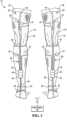
- the carrier material 32 may include one or more alignment indicia 62 from which relative orientation may be quickly identified.
- These indicia 62 may include, anatomical markers, such as indications or holes for a knee cap or ankle bone, marks to align with other equipment, marks to align with anatomical reference planes or the like.
- the indicia 62 may include a line that extends along a majority of the length of the stocking/sleeve, and/or at certain anatomical waypoints along the length of the limb, such as shown in FIG. 3 .
- the line(s) may provide a quick visual reference to determine overall relative orientation of the sleeve, while also calling attention to any localized twisting.
- the carrier material 32 may be a separate therapeutic or diagnostic device that is already common in surgical applications. For example, in a spinal procedure involving one or more of the L2-S 1 vertebrae, it is known that nerve roots innervating the leg muscles may lie within the surgical area. During such procedures, however, compression-type anti-embolism stockings (Thrombo-Embolic-Deterrent (“TED") hose) are typically provided around a subject's legs and feet to discourage blood clot formation.
- TED Thrombo-Embolic-Deterrent
- the carrier material 32 may be an elastic sleeve/stocking configured to apply a compressive force to the subject's leg when worn, thus eliminating the need for separate TED hose.
- the carrier material 32 may include, for example, a blood pressure cuff worn around the subject's arm (or else may include functionality similar to that of a standard blood pressure cuff).
- the carrier material 32 serves a function outside of that of a dedicated neuromuscular sensing device, and thus provides efficiencies in pre-op preparation and planning, while also allowing monitoring access on sometimes crowded limbs.
- the system 10 may further include one or more elongate medical instruments 70 (i.e., stimulators 70) that are capable of selectively providing a stimulus 72 within the intracorporeal treatment area 12 of the subject 14.
- the elongate medical instrument 70 may include a probe 76 (e.g., a ball-tip probe, k-wire, or needle) that has an electrode 78 disposed on a distal end portion.
- the electrode 78 may be selectively electrified, at either the request of a user/physician, or at the command of the processor 28, to provide an electrical stimulus 72 to intracorporeal tissue of the subject.
- the elongate medical instrument 70 may include a dilator, retractor, clip, cautery probe, pedicle screw, or any other medical instrument that may be used in an invasive medical procedure. Regardless of the instrument, if the intended artificial stimulus is an electrical current, the instrument 70 may include a selectively electrifiable electrode 78 disposed at a portion of the instrument that is intended to contact tissue within the intracorporeal treatment area 12 during the procedure.
- the user/surgeon may selectively administer the stimulus to intracorporeal tissue within the treatment area 12 to identify the presence of one or more nerve bundles or fibers.
- the user/surgeon may administer the stimulus, for example, upon depressing a button or foot pedal 74 that is in communication with the host system 20.
- the electrical stimulus 72 may, for example, be a periodic stimulus that includes a plurality of sequential discrete pulses (e.g., a step pulse) provided at a frequency of less than about 10 Hz, or from about 1 Hz to about 5 Hz, and preferably between about 2 Hz and about 4 Hz. Each pulse may have a pulse width within the range of about 50 ⁇ s to about 400 ⁇ s.
- the discrete pulse may have a pulse width within the range of about 50 ⁇ s to about 200 ⁇ s, or within the range of about 75 ⁇ s to about 125 ⁇ s. Additionally, in some embodiments, the current amplitude of each pulse may be independently controllable.
- the electrical stimulus 72 may cause the nerve to depolarize, resulting in a mechanical twitch of a muscle that is innervated by the nerve (i.e., an artificially-induced mechanical muscle response).
- a mechanical twitch of a muscle that is innervated by the nerve i.e., an artificially-induced mechanical muscle response.
- the magnitude of the response/twitch may be directly correlated to the distance between the electrode and the nerve, the impedance between the electrical stimulus and the ground patch, and the magnitude of the stimulus current.
- a lookup table or other suitable function may be employed to provide an approximate distance between the electrode and the nerve, given a known stimulus magnitude and a measured mechanical muscle response.
- the system 10 may generally operate by applying a stimulus 72 to an intracorporeal treatment area 12 of the subject 14 via the stimulator 70, and then monitoring the resulting neuromuscular activity to determine the existence of an artificially induced muscle response and quantify the same.
- the host system 20 may be configured to alert a surgeon to a detected induced muscle response, to indicate a determined distance between the stimulator and a nerve, to display one or more signal traces representative of the sensed muscle response(s), to record event information for subsequent review and analysis, and/or to perform other ancillary functionality.
- the on-board device processor 42 may be operative to pre-process, filter, and/or down-sample the raw sensor output in a manner that minimizes the amount of information that is required to be streamed from the sensor device 30 to the host system 20.
- this on-board processing may involve pre-detecting events, and transmitting only sensor data that likely represents an induced neuromuscular response.
- this on-board processing may involve transmitting sensor data representative of an induced neuromuscular response at a first resolution and/or sampling rate and transmitting all other sensor data at a second, comparatively slower or lower resolution and/or sampling rate.
- FIG. 4 schematically illustrates a method 90 of locally processing a plurality of MMG output signals 38 to reduce total data transmission throughput from the wireless communication circuitry 44.
- the method 90 is performed by the device processor 42 and begins by the processor 42 receiving each MMG output signal generated by the plurality of neuromuscular sensors 34 (at 92) and storing a portion of each signal (i.e., buffering) into electrically erasable memory associated with the processor 42 (at 94) for further analysis.
- the portion of each signal that is recorded at 94 may either be a rolling period of time that follows a first-in-first-out scheme as new data is received, or else may be a triggered period of time that begins at or shortly after the occurrence of some event (e.g., a stimulation).
- a rolling period of time may continuously be buffered upon receipt, then filtered to remove portions of the signal that have a high probability of not representing an induced muscle response, and a triggered period of time may then be buffered from this filtered rolling window for further analysis.
- the triggered period of time may begin at or very shortly after the administering of a stimulus 72 by the stimulator 70.
- a strategy is premised on the idea that induced muscle responses occur following the administration of a stimulus, and if no stimulus has been provided, it is unlikely that any sensed motion represents an induced response. Similarly, if a stimulus has been provided and no muscle response is detected within an expected window of time following the stimulus, it is likely that the stimulus was either too weak or too distant from a nerve to cause that nerve to depolarize.
- the length/duration of the buffered portion of each signal may either be fixed or variable according to one or more attributes of the subject 14 and/or of the signal itself.
- Relevant attributes of the patient that could affect the duration of the response window include the subject's body mass index (BMI), or the existence of diabetes, neuropathy, degenerative nerve conditions, muscle fatigue, or other such factors that are known to affect nerve conduction velocity and/or muscular response.
- BMI body mass index
- one relevant attribute of the signal that could be used to alter the duration of the window includes, for example, the initial slope of the acceleration profile when movement is first detected.
- the length of the buffered data should be from about 75 ms to about 300 ms, or even more narrowly from about 100 ms to about 200 ms.
- This filtering may include, for example, the application of a high pass filter, low pass filter, removal of signal content that is persistent across and seemingly uninfluenced by the application of multiple stimuli, or signal content that is otherwise attributable to a gross translation or rotation of the limb.
- the processor 42 may detect gross translations or rotations by virtue of having a plurality of mechanical sensors 36 held in varying positions around the limb by the carrier material 32. More specifically, if each of the plurality of sensors 36 output a respective signal 38 that, when viewed collectively suggests a coordinated translation or rotation (i.e., a global motion rather than a local motion), any signal content specific to that global motion can be digitally removed. To accomplish this motion detection, the local processor 42 may begin by ensuring that the received signals are coordinated in time (e.g., through the use of time-stamps upon receipt, clock synchronization, or other buffering or signal processing techniques).
- the processor 42 may then examine the collection of MMG output signals to identify any motion that is common between the sensors or that is otherwise indicative of a gross translation or rotation of the limb. If any such motion is identified, it may be filtered, attenuated, or otherwise removed from each respective output signal 38 prior to the system performing any further analysis.
- the processor 42 may perform this gross motion rejection by mapping each sensor reading to a three dimensional (virtual) solid model of the limb. This mapping may be accomplished by understanding the number and relative placement of the sensors on the device 30, and by mapping the actual sensed motion to corresponding points on a virtual solid model of the limb.
- the processor 42 may receive an indication of the subject's anatomy (e.g., body mass index (BMI), limb circumference, or percent body fat) to scale the size and presumed elastic modulus of the virtual solid model.
- BMI body mass index
- the global motion may then be extracted from the model, for example, by examining the motion of, for example, the centroid of the model or of a rigid body diagram/representation of the limb.
- using a virtual limb model may not only enable gross motion detection by inspecting the motion of the model, itself, but it may also permit virtual sensor points to be dropped on the model, which may provide a more complete/higher resolution picture of how the limb is responding/moving. This better understanding of the limb motion may then enable greater accuracy when detecting the occurrence and magnitude of an artificially neuromuscular response, while also serving to reduce the overall noise floor of the system.
- the processor 42 may determine (at 98) if the MMG output signal 38 from any one or more of the plurality of sensors 34 is representative of an artificially induced neuromuscular response. If the processor 42 concludes that the output signal 38 is representative of an induced response, processor 42 may transmit one or more of the buffered MMG output signals 38 to the host system 20 via the wireless communication circuitry 44 (at 100).
- the processor 42 may continue buffering and analyzing in a continuous manner while not transmitting anything to the host system 20 (i.e., the processor 42 would transmit the one or more buffered MMG outputs signals only if the MMG output signal from one or more of the plurality of mechanical sensors is determined to be representative of an artificially induced neuromuscular response).
- the processor 42 may continue to transmit signal data (at 102) to the host system 20 even if no event is detected.
- the processor 42 may reduce the sampling frequency and/or digital resolution of any signal data that is not believed to be representative of an induced muscle response prior to transmitting.
- the processor 42 may transmit comparatively higher quality data (i.e., faster sampling rate and/or greater resolution) to the host system 20 for display, further analysis, and/or recordation.
- the processor 42 may be configured to automatically perform one or more signal processing algorithms or methods to determine whether a mechanical movement sensed embodied by an output signal 38 is representative of an artificially-induced mechanical muscle response or if it is merely a subject-intended muscle movement and/or an environmentally caused movement.
- These processing algorithms may be embodied as software or firmware, and may either be stored locally on the processor 42, or may be readily assessable by the processor 42.
- the signal processing algorithms used to recognize an induced response may involve one or more analog detection techniques such as described, for example, in US Patent No. 8,343,065, issued on January 1, 2013 (the '065 Patent), one or more digital detection techniques, such as described in US 2015/0051506, filed on August 13, 2013 (the ⁇ 506 Application), and/or one or more triggered techniques, which are described above and in US Patent Application Serial No. 15/995,879, filed on June 1, 2018 .
- the processor may examine one or more aspects of the MMG output signal 38 in an analog/time domain to determine if the sensed response is an artificially-induced response of the muscle to the stimulus.
- these analog aspects may include, for example, the time derivative of acceleration, or the maximum amplitude of the initial response.
- the processor 42 may indicate that the sensed motion is likely representative of an induced muscle response if the time derivative acceleration of the output signal (i.e., the initial rise slope of the primary muscle contraction) exceeds a predefined threshold.
- the processor may compare the frequency components of the MMG output signal (i.e., using the signal converted into the frequency domain) with the frequency of the applied stimulation to determine whether the sensed motion and/or candidate events were induced by the applied stimulus.
- Such a technique may be made more robust by considering only events or muscle activity that occurs within the period of time following the stimulus where an induced response is likely to occur and/or by aggressively filtering/attenuating or ignoring the signal outside of expected periods of time prior to applying the signal processing algorithms.
- the signal processing algorithms may include one or more supervised learning algorithms that are operative to classify any sensed motion into one of a plurality of classifications that include at least whether the motion is, or is not representative of an artificially-induced mechanical response of the muscle. Both classifications may provide valuable information to an operating surgeon during a procedure. Affirmatively detecting a response informs the surgeon that a nerve is proximate to the stimulator/tool, and to proceed with caution. Conversely, determining that no induced response occurred, particularly if a stimulus is provided, informs the surgeon that the nerve is not present and they can proceed in their normal manner.
- a supervised learning algorithm is an algorithm that attempts to classify a current sample using observations made about prior samples and their known classifications. More specifically, the algorithm attempts to construct and/or optimize a model that is capable of recognizing relationships or patterns between the training inputs and training outputs, and then the algorithm uses that model to predict an output classification given a new sample.
- supervised learning algorithms include neural networks, support vector machines, logistic regressions, naive Bayes classifiers, decision trees, random forests, or other such techniques or ensembles of techniques.
- FIG. 5 schematically illustrates an embodiment of a supervised learning algorithm 110 that may be used to classify one or more buffered periods of the MMG output signal(s) 38 into a binary classification (i.e., an artificially induced muscle response 112, or not an artificially induced response 114). While the supervised learning algorithm 110 may certainly be applied on a sensor-by-sensor basis (which may aid in classifying the output from any one sensor channel), in one embodiment, the algorithm 110 may consider the MMG output signals 38 from a plurality of the sensors 34, collectively (e.g., within the analysis buffer as described above).
- Such a strategy may recognize that a muscle response on a first side of the limb may cause a detectable response in one or more sensors located apart from that muscle by virtue of wave propagation and/or via the dynamics of the limb itself.
- nerve roots and nerve bundles often serve to innervate multiple muscle groups, though each to varying degrees.
- one manner of detecting the induced depolarization of a nerve is to examine the coordinated responses of all muscles the stimulated nerve innervates.
- Such a multi-channel analysis is generally well suited for supervised learning algorithms.
- the processor 42 may initially characterize the one or more MMG output signals 38/buffered samples and/or any recognized muscle motion according to one or more analog characteristics 118, frequency characteristics 120, and/or time-series/image characteristics 122. The processor may then use a model 124 constructed and/or optimized on the basis of a plurality of pre-classified training samples 126 to make an informed classification that minimizes an established error function or maximizes the probability of an accurate prediction.
- the one or more analog characteristics 118 may include, for example, max/min acceleration amplitudes, max/min velocity amplitudes, time derivative of acceleration, signal rise time, or curve fitting coefficients.
- the one or more frequency characteristics 120 may include, for example, FFT coefficients, peak frequencies, peak frequency magnitudes, harmonic frequencies, or frequency fall-off.
- the time-series/image characteristics 122 may include a snapshot of a graph of the MMG output 38 over time.
- the supervised learning algorithm 110 may model these characteristics 118, 120 in the aggregate to predict the nature of the muscle event with a greater accuracy. Furthermore, in some situations, the visual attributes of an induced response may tell a more complete story than any one parameter or collection of parameters could. As such, in an embodiment, the supervised learning algorithm 110 may include an image based classifier that may attempt to classify a muscle response on the basis of a visual similarity with other previously identified induced responses.
- the supervised learning algorithm 110 may employ an ensemble approach to generating the output classification.
- the model 124 may include a plurality of different models/approaches that may be combined according to a weighting/costing formula to provide improved redundancy/voting.
- the ensemble approach may use the output of one or more approaches/models as an input of another model.
- the analog and/or frequency based detection techniques discussed in the '065 Patent and/or in the '506 Application may output a probability or likelihood that an event in question is representative of an induced response.
- each model including any supervised learning algorithm may feed into a separate algorithm that may output a binary response or probability based upon the outcomes of the various models. This approach may use voting algorithms, probability combinations, and/or separate supervised learning algorithms to provide an output based on the prediction of each constituent model.
- the processor 42 may examine each received output signal 38 individually to see if any respective output signal exhibits traits that are likely the product of an induced muscle response. The processor 42 may also collectively examine all received output signals 38 to determine if the motion/response of various portions of the limb, together, suggest the occurrence of an induced muscle response. In one configuration, the processor 42 may initially screen each output signal individually to determine if any one or more output signals are indicative of the occurrence of an artificially induced neuromuscular response. This initial screening may occur by examining the output signals in real-time or following the application of one or more filtering/noise reduction techniques.
- the process of 42 may then collectively analyze a plurality of the buffered output signals to determine if the coordinated response is also indicative of an induced muscle response. If the signals individually and collectively indicate an induced muscle response, the processor 42 may then transmit the buffered signals to the host system 20 (at 100 in FIG. 4 ).
- the sensing device 30 may include a resident alert system that is operative to provide one or more visual and/or audible alerts to a surgeon or surgical team.
- the alert system may be embodied as a combination of software/firmware executed by the processor 42 in combination with hardware configured to illuminate and/or broadcast an audible signal.
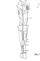
- FIG. 2 illustrates a plurality of lighting elements 130, such as light emitting diodes, that may illuminate at the direction of the processor 42 or other monitoring circuitry associated with the sensor 34 itself.
- the alert system may be configured to provide a first alert 132 if one or more of the MMG output signals 38 is indicative of the occurrence of an artificially induced neuromuscular response, and provide a second alert 134 if the plurality of the buffered MMG output signals are collectively indicative of the occurrence of an artificially induced neuromuscular response.
- the first alert 132 may be, for example, be a light that is illuminated on the particular sensor 34 that sensed the induced response.
- the second alert 134 may be, for example, illuminating a plurality of lights across all of the sensors 34 (i.e., to indicate collective detection).
- the first alert 132 may be different in at least one of tone or color from the second alert 134 to draw attention to the differences.
- the alert system may include a both a light source provided with each sensor and a speaker provided with the device 30.
- the first alert 132 may include a first color illuminated from a first light source provided with the sensor 34 that generated the MMG output signal indicative of the artificially induced neuromuscular response and may further include a first alert tone played via the speaker.
- the second alert 134 may then include at least one of: a second color illuminated from the first light source and a second alert tone played via the speaker; or a third color illuminated from a second light source provided apart from the sensor 34 that generated the MMG output signal indicative of the artificially induced neuromuscular response and a second alert tone played via the speaker.
- the first color is different from the second color
- the first tone is different from the second tone
- the third color is the same or different from the first color.
- the communication of an alert via the device 30 would not be contingent on the existence or quality of the wireless connection between the device 30 host system 20, and the surgeon's attention may be called to the discrepancy between what the device is alerting to and what the host system 20 might be displaying.
- the quality and/or existence of the wireless connection may be evaluated by periodically transmitting a connection diagnostic data packet between the device 30 and the host system 20.
- This data packet maybe a low-footprint, nominal transmission that is performed solely to evaluate whether the connection is still active and/or whether the fidelity of the connection is sufficient to convey data promptly to the host system 20.
- the diagnostic data packet may be a checksum that may validate the previously transmitted data, a time stamp, or similar de minimis transmissions.
- the sensing device 30 may transmit the connection diagnostic packet on a regular, periodic interval.
- the host system 20 may utilize the existence and/or content of the received connection diagnostic packet to evaluate the connection, and alert a surgeon that it may not be proper to infer that a lack of a response/alert is the result of a lack of an induced muscle response. Instead, the lack of a response might the result of a compromised wireless connection between the host system and the sensing device. If the host system 20 detects that the wireless connection has been broken or if it is of such a low quality that alerts to the surgical team may be compromised, the host system 20 may proactively provide a visual and/or audible alert to the surgical team so that the connection maybe repaired or other precautions taken.
- the host system 20 may be operative to transmit the connection diagnostic packet to the sensing device 30 on a regular, periodic interval.
- the processor 42 may provide a visual and/or audible alert via the alert system described above.
- the system 10 may include a wireless stimulator 150.
- the wireless stimulator 150 may include a power supply 152 and control circuitry 154 that is operative to administer an electrical stimulus 156 in a bi-polar manner between two electrodes 158, 160 provided on a distal end portion 162 of the stimulator 150.
- the wireless stimulator 150 may include communication circuitry 164 that enables it to wirelessly communicate with the host system 20 and/or the sensor device 30.
- the magnitude and/or the frequency of the stimulus 156 maybe adjusted according to one or more control signals received via the communication circuitry 164.
- the communication circuitry 164 may transmit an indication that a stimulus has been applied via of the electrodes 158, 160. This provided indication may be received, for example, by the host system 20 and/or communicated to the sensing device 30 to enable the sensing device 30 to begin buffering the received MMG output signals 38 for further analysis.
- the sensing device 30 may still be capable of recognizing the occurrence of the stimulus by monitoring changes in one or more electrical parameters of the subject. More specifically, when an electrical stimulus is applied to the body, the electrical potential of all tissue within the body may momentarily change. When monitored in an electromyography context, such an inrush is generally referred to as a stimulus artifact. While a stimulus artifact is generally viewed as a negative quality (i.e., it can complicate electromyography measurements and potentially obscure changes in the muscle action potential), when used with MMG, the stimulus artifact may provide a near real-time indication that a stimulus has been administered.
- the sensing device 30 may include a pair of electrodes 170 in communication with the processor 42 for the purpose of monitoring one or more electrical parameters of the subject 14.
- the processor 42 may be configured to identify the occurrence of a an electrical stimulus 72, 156 provided apart from the device 30 by recognizing a momentary change in one or more of the monitored parameters (i.e., evidence of a stimulus artifact).
- These electrodes 170 may include any combination of skin-applied transdermal electrodes and invasive needle electrodes.
- the pair of electrodes 170 may include two spaced transdermal electrodes held in contact with the skin of the subject 14.
- the pair of electrodes 170 may include one needle electrode extending through the skin, and one transdermal electrode. Finally, in one embodiment, the pair of electrodes 170 may include two spaced needle electrodes. As noted above, in one configuration, the processor 42 may begin buffering the plurality of MMG output signal 38 following the identification of the electrical disturbance and/or stimulus artifact.
Description
- The present disclosure relates generally to a surgical diagnostic system employing a wireless sensing device for detecting artificially induced neuromuscular activity.
- Traditional surgical practices emphasize the importance of recognizing or verifying the location of nerves to avoid injuring them. Recent advances in surgical techniques include the development of techniques using ever smaller incisions, such as minimally invasive surgical procedures, and the insertion of ever more complex medical devices. With these advances in surgical techniques, there is a corresponding need for improvements in methods of detecting and/or avoiding nerves.
- In many surgical procedures, it may be common to include ancillary monitoring devices or therapeutic devices provided around limbs or other anatomy of the subject. Each device may include wires or tubes that extend between the patient-contacting component and a separate monitoring/control station. These wires/tubes may create a congested area immediately surrounding the patient, which may potentially interfere with the surgical team's ability to move freely within the operating room.
- Therefore, while the need for nerve detection/monitoring exists, the corresponding wiring that could extend from a purely wired implementation may further congest an already crowded operating suite.
US9084550 - A sensing device for detecting an artificially induced neuromuscular response within a limb of a subject includes a plurality of mechanical sensors, wireless communication circuitry, and a processor in electrical communication with each of the plurality of mechanical sensors and wireless communication circuitry. Each sensor is operative to monitor a mechanical response of a different muscle group of the limb and generate a mechanomyography (MMG) output signal corresponding to the monitored motion. According to the invention, the processor receives and buffers a portion of each MMG output signal, determines if the MMG output signal from any one or more of the plurality of mechanical sensors is representative of an artificially induced neuromuscular response, and transmits one or more of the buffered MMG output signals to a host system only if the output signal from one or more of the sensors is determined to be representative of an artificially induced neuromuscular response.
- A system for detecting the presence of a nerve within an intracorporeal treatment area of a subject includes a host system, a first sensing device and a second sensing device. The host system may include a display for outputting data and/or alerts to a surgical team.
- The first sensing device may include a first plurality of mechanical sensors, each operative to monitor a mechanical response of a different muscle group of a first portion of the subject and each configured to generate a respective mechanomyography (MMG) output signal corresponding to the monitored motion. The first device further includes a first processor in communication with each mechanical sensor of the first plurality of mechanical sensors and configured to receive each of the generated MMG output signals from the first plurality of mechanical sensors.
- The second sensing device may include a second plurality of mechanical sensors, each operative to monitor a mechanical response of a different muscle group of a second portion of the subject and each configured to generate a respective mechanomyography (MMG) output signal corresponding to the monitored motion. The second device further includes a second processor in communication with each mechanical sensor of the second plurality of mechanical sensors and configured to receive each of the generated MMG output signals from the first plurality of mechanical sensors.
- To minimize the chance of wires interfering with the surgical procedures each of the first processor and second processor are in wireless digital communication with the host system and are each operative to wirelessly transmit at least a portion of one or more MMG output signals to the host system for output via the display.
- The features and advantages and other features and advantages of the present technology are readily apparent from the following detailed description when taken in connection with the accompanying drawings.
- "A," "an," "the," "at least one," and "one or more" are used interchangeably to indicate that at least one of the item is present; a plurality of such items may be present unless the context clearly indicates otherwise. All numerical values of parameters (e.g., of quantities or conditions) in this specification, including the appended claims, are to be understood as being modified in all instances by the term "about" whether or not "about" actually appears before the numerical value. "About" indicates that the stated numerical value allows some slight imprecision (with some approach to exactness in the value; about or reasonably close to the value; nearly). If the imprecision provided by "about" is not otherwise understood in the art with this ordinary meaning, then "about" as used herein indicates at least variations that may arise from ordinary methods of measuring and using such parameters. In addition, disclosure of ranges includes disclosure of all values and further divided ranges within the entire range. Each value within a range and the endpoints of a range are hereby all disclosed as separate embodiment.
-
-
FIG. 1 is a schematic diagram of a neural monitoring system for detecting an artificially-induced mechanical muscle response. -
FIG. 2 is an enlarged schematic anterior view of a sensing device provided on a leg of a subject. -
FIG. 3 is a schematic anterior view of a first sensing device provided on a first leg of a subject a second sensing device provided on a second leg of the subject, and host system in communication with the fist sensing device and the second sensing device. -
FIG. 4 is a schematic flow diagram for locally processing a plurality of MMG output signals to reduce total data transmission throughput. -
FIG. 5 is a schematic diagram of a signal processing algorithm, including a supervised learning algorithm, for classifying a sensed muscle motion as being either an induced response or not an induced response. -
FIG. 6 is a schematic side view of a wireless bi-polar stimulator probe. -
FIG. 7 is a schematic anterior view of a sensing device provided on a leg of a subject with a pair of electrodes for monitoring an electrical parameter of the leg. - The present disclosure provides a wireless sensing device for detecting an artificially induced neuromuscular response of a subject. The device may include an array of neuromuscular sensors that are locally monitored on the device and collectively networked with a separate host system via a wireless radio frequency (RF) communication circuitry.
- The sensor array of the present device may be adapted to monitor a plurality of different muscle groups of the subject. Each neuromuscular sensor in the array may be held in contact with the skin of the subject immediately adjacent to each monitored muscle group. In most embodiments, each sensor in the array includes a mechanical sensor that is operative to monitor the mechanical motion of the adjacent muscle group and to generate an output signal corresponding to that sensed motion. Using various processing techniques, the system may then be capable of discerning whether the sensed mechanical motion is representative of an artificially induced muscle response.
- While the individual output signals and signal data may be useful for identifying induced muscle responses and determining the proximity of a nerve to an invasive stimulator, unconstrained and continuous wireless data transmission incurs a significant power draw that may quickly deplete onboard power stores/batteries. As such, in certain embodiments, the sensing device may include a local processor that is capable of performing at least a preliminary analysis on the monitored responses and then transmitting only sensor data that likely represents an induced neuromuscular response. Alternatively, the local processor my downsample and/or reduce the resolution of any sensor data that is not representative of an induced neuromuscular response prior to transmission. Because induced responses tend to be sporadic and somewhat infrequent, this filtering technique greatly reduces that amount and frequency of data that must be transmitted and the corresponding power consumption of the onboard communications circuitry. This may permit a reduction in the size of a required battery and/or may increase the duration of device use on a single charge.
- The present "filtering" technique serves to reduce the quantity and/or frequency of wireless data transmission by only transmitting full resolution data when an induced muscle response is likely to exist. In embodiments where data transmission only occurs when the processor detects something, periods of data transmission may be interpreted as being representative of an induced response, and periods of no transmission may be interpreted as being representative of a lack of an induced response (which is also significantly informative to a surgeon). Unfortunately, in such an embodiment, the lack of a response may also be caused by a drop in wireless connectivity, where even if a response were to exist, it would not be communicated. To address this concern, in some embodiments, a connection diagnostic data packet may be periodically communicated between the sensing device and the host system to provide an indication of the fidelity of the wireless communication link. In some embodiments, the connection diagnostic packet may be a checksum or other diagnostic packet that is transmitted back to the sensing device upon conclusion of a transmitted message. If the fidelity of the communication link drops or entirely falls out, as may be determined via the diagnostic packet, the system may provide an alert to indicate that the negative inference should not be trusted (i.e., the negative inference that no transmission = no induced response).
- In some embodiments, the local processor may detect the likelihood of an induced muscle response by analyzing the sensor signals individually and/or in the collective. To perform this analysis, each signal may be locally buffered by the processor across a rolling period, and then the buffered signals may be analyzed to determine signal traits indicative of an induced response. Processing techniques that may be employed involve techniques to actively filter out noise, gross motion, and/or signal content outside of an expected response window, while also examining the signal or signals from the sensors for attributes or patterns that are indicative of an induced response.
- To minimize pre-operative setup while reducing the potential for error, the sensor device may be provided as an integrated unit that may be affixed to the subject by either securing it around the limb (similar to a blood pressure cuff) or by pulling the device onto the subject, such as with anti-embolism stockings. In doing so, the carrier material may locate the array about the subject in a quicker manner than if each sensor was individually placed.
- Referring to the drawings, wherein like reference numerals are used to identify like or identical components in the various views,
FIG. 1 schematically illustrates aneural monitoring system 10 that may be used to identify the presence of one or more nerves within anintracorporeal treatment area 12 of asubject 14, such as during a surgical procedure. As will be described in greater detail below, thesystem 10 may monitor one or more muscles of thesubject 14 for a neuromuscular response that is indicative of a stimulus-induced depolarization of a nerve (i.e., an artificially induced neuromuscular response). If a response of the muscle to the stimulus is detected during the procedure, thesystem 10 may provide an alert or indication to the surgeon, which may enable the surgeon to take an appropriate action if such action is warranted. - As used herein, an "artificially induced neuromuscular response" is a response of a muscle to a depolarizing stimulus that is applied to a nerve innervating the muscle. In general, the response is "artificially induced" because the nerve is depolarized directly by the stimulus, instead of, for example, the stimulus being received through an intermediate sensory means (e.g., sight, sound, taste, smell, and touch). An example of a stimulus that may cause an "artificially-induced" muscle response may include an electrical current applied directly to the nerve or to intracorporeal tissue or fluid immediately surrounding the nerve. In such an example, if the applied electrical current is sufficiently strong and/or sufficiently close to the nerve, it may artificially cause the nerve to depolarize (resulting in a corresponding contraction of the muscle or muscles innervated by that nerve). Other examples of such "artificial stimuli" may involve mechanically-induced depolarization (e.g., physically stretching or compressing a nerve, such as with a tissue retractor), thermally-induced depolarization (e.g., through ultrasonic cautery), or chemically-induced depolarization (e.g., through the application of a chemical agent to the tissue surrounding the nerve).
- During an artificially induced neuromuscular response, a muscle innervated by the artificially depolarized nerve may physically contract or relax (i.e., a mechanical response) and/or the electrical potential throughout the muscle may be altered. Mechanical responses may primarily occur along a longitudinal direction of the muscle (i.e., a direction aligned with the constituent fibers of the muscle), though may further result in a respective swelling/relaxing of the muscle in a lateral direction (which may be substantially normal to the skin for most skeletal muscles). This local movement of the muscle during an artificially-induced mechanical muscle response may be measured relative to the position of the muscle when in a non-stimulated state.
- The
neural monitoring system 10 may generally include ahost system 20 and asensing device 30 that may cooperate to detect a neuromuscular response of a muscle to astimulus 72 provided by astimulator 70. As schematically shown inFIG. 1 , thehost system 20 may include one ormore input devices 22 that are operative to receive information from the surgeon, one ormore output devices 24 that are operative to communicate alerts or to provide informational feedback to the surgeon,communication circuitry 26 operative to communicate with thesensing device 30, and aprocessor 28 that is operative to at least manage the flow of information between theinput devices 22,output devices 24 andcommunication circuitry 26. - In general, the one or
more input devices 22 may include a keyboard, a mouse, and/or a digitizer provided with a touch-screen display. These devices may receive pre-operative case information or may permit a surgeon to alter various intraoperative parameters, alarm limits, or other case information before or during a procedure. In some embodiments, thestimulator 70 and/or afoot pedal 74 may provide additional input to thehost system 20. This input may be in the form of an analog or digital signal that is indicative of the delivery and/or magnitude of a stimulus. Theoutput device 24 may include, for example, a visual display such as an LED/LCD display, one or more indicator lights, or speakers capable of providing an audible alert to the surgeon. - The
sensing device 30 is the portion of thesystem 10 that directly contacts the subject 14 and is responsible for, at a minimum, sensing/detecting neuromuscular responses of the subject 14. Thesensing device 30 may include acarrier material 32 that is operative to be secured to the subject 14, and a plurality of neuromuscular sensors 34 (i.e., a sensor array) that are each operative to monitor a neuromuscular response of a different muscle group of the subject 14. - From the perspective of the
sensing device 30, the carrier material's main purpose is to hold theneuromuscular sensors 34 in relatively stable contact with the skin of the subject. While the present technology has a beneficial use with electromyography (EMG) (i.e., by ensuring that needle electrodes are held in firm, relative position in the muscle without much risk of falling out), the full functionality and accuracy of thedevice 30 is best realized when theneuromuscular sensors 34 are configured to monitor the mechanical responses of the various muscles. As such, in an embodiment, at least a plurality of theneuromuscular sensors 34 include amechanical sensor 36, such as for example, a strain gauge, a pressure/force transducer, a position encoder, an accelerometer, a piezoelectric material, or any other transducer or combination of transducers that may convert a physical motion into a variable electrical signal. - At a device-level, each of the plurality of
neuromuscular sensors 34 may provide anoutput signal 38 that corresponds to or that is representative of its sensed level of neuromuscular activity. In some embodiments, eachsensor 34 may includecommunication circuitry 40 to facilitate transmission of the output signal to a local device processor 42 (note that thecommunication circuitry 40 may be integral to themechanical sensor 36, or may not be required depending on the architecture of the array). In effect, this collection of wired sensors to thelocal processor 42 may form a device-level, serial network that may be managed by theprocessor 42 or by a secondary component operating in conjunction with theprocessor 42. - As schematically shown in
FIG. 2 , thesensing device 30 may includewireless communication circuitry 44 that is operative to digitally communicate with thecommunication circuitry 26 of thehost system 20, anantenna 46, apower source 48, and thelocal processor 42 in communication with each of these. In general, processors used with the present system 10 (e.g.,processors 28, 42) may each be embodied as one or multiple digital computers, data processing devices, and/or digital signal processors (DSPs), which may have one or more microcontrollers or central processing units (CPUs), read only memory (ROM), random access memory (RAM), electrically-erasable programmable read only memory (EEPROM), a high-speed clock, analog-to-digital (A/D) circuitry, digital-to-analog (D/A) circuitry, input/output (I/O) circuitry, and/or signal conditioning and buffering electronics. - In some embodiments, the
power source 48 may comprise a wired power supply, such as an alternating-current line voltage. Such a design, however, negates some of the benefits of the wireless communications and wireless nature of the device, since wires extending from thesensing device 30 would still be required. Because an object of the present disclosure is to reduce or eliminate the need for wires extending from thesensing device 30, in a more preferred embodiment, thepower source 48 is a battery that is provided locally with thesensing device 30. The battery may have any suitable construction/composition, including, but not limited to a nickel metal hydride (NiMH) composition or a lithium-ion (Li-ion) composition. Physically, the battery may be provided as a portion of an integrated package together with theprocessor 42 and/orwireless communication circuitry 44, though this packaging configuration is not strictly necessary. In some embodiments, to provide a complete, singular device, the battery and/or any integrated packaging may be directly affixed to thecarrier material 32. In doing so, the power source is local to and coupled with thesensing device 30, thus reducing the need for a wired connection to thedevice 30. - The
wireless communication circuitry 44 may include any combination of signal processors, power amplifiers, signal filters, transceivers, and the like that may be required to digitally communicate with a physically separate device via the coupledantenna 46. In some embodiments, theantenna 46 may include one or more conductive fibers or films that are integrated with/on thecarrier material 32. In other embodiments, theantenna 46 may be internal to thecommunication circuitry 44. As further illustrated inFIG. 2 , in some embodiments, theantenna 46 may be located at a distal end portion of thesensing device 30, which may surround or abut a distal end portion of the subject's limb. Locating theantenna 46 in this manner may position it apart from large, fluidly-dense bodies, such as the subject's torso, which could attenuate and/or distort transmission signals. - The communication between the
antenna 46 and thecommunication circuitry 26 of thehost system 20 may be unidirectional or bi-directional, and may be performed according to one or more established or subsequently developed radio frequency (RF) protocols. Suitable RF protocols may include those according to IEEE 802.11, IEEE 802.15, a Bluetooth standard, a ZigBee standard, near-field communication (NFC) standards, RFiD or the like. - The
wireless communication circuitry 44 may generally operate at the direction of theprocessor 42 and/or on the basis of digital information supplied by theprocessor 42. In some embodiments, thewireless communication circuitry 44 may be the sole manner of digitally communicating to/from thesensing device 30. For the purpose of this disclosure, it should be noted that "digitally communicating" is not intended to encompass visual or audible alerts that may be communicated directly from thedevice 30 to the surgical team. - As shown in
FIG. 3 , whenmultiple sensor devices 30 are utilized concurrently, eachsensor device 30 may maintain its own local sensor-level network while also wirelessly communicating to thehost system 20 via device-specificwireless communications circuitry 44. An example of such a scenario might be if thesystem 10 was required to monitor both of the subject's legs for neuromuscular activity. At a network level, in order for each device to transmit event data to thehost system 20 concurrently, thesystem 10 may utilize a wireless communications protocol that has the capability of managing data flow from a plurality of different sources on the network, as opposed to one that relies on 1-to-1 pairing relationships. - In the embodiment provided in
FIG. 3 , afirst sensor device 50 is provided on afirst limb 52, and asecond sensor device 54 provided on asecond limb 56. Eachdevice wireless communication circuitry 44 that may be in wireless digital communication with anadjacent host station 20. If required, typical network infrastructure (e.g., a switch or router) may be provided to modulate communications between the various devices. As shown, thefirst sensor device 50 may manage afirst array 58 ofneuromuscular sensors 34, and thesecond sensor device 54 may monitor asecond array 60 ofneuromuscular sensors 34. As noted above, in a preferred embodiment, some or all of theneuromuscular sensors 34 may include sensors capable of sensing a mechanical motion and then generating an electrical output signal representative of that sensed motion (i.e., a mechanomyography signal). - In embodiments utilizing a
carrier material 32 to position the sensor array with respect to the subject, the specific nature of thecarrier material 32 may vary based on the location of the surgical site and nature of the surgical procedure. In many cases thecarrier material 32 may resemble a cuff or sleeve that is secured around a limb of the subject. Such a design may be suitable, for example, with a spinal procedure where nerves existing within the surgical site are known to innervate peripheral muscles of the arms or legs. - To assist the medical staff in achieving proper alignment of the sleeve on the leg of the subject, the
carrier material 32 may include one ormore alignment indicia 62 from which relative orientation may be quickly identified. Theseindicia 62 may include, anatomical markers, such as indications or holes for a knee cap or ankle bone, marks to align with other equipment, marks to align with anatomical reference planes or the like. In one embodiment, theindicia 62 may include a line that extends along a majority of the length of the stocking/sleeve, and/or at certain anatomical waypoints along the length of the limb, such as shown inFIG. 3 . In this embodiment, the line(s) may provide a quick visual reference to determine overall relative orientation of the sleeve, while also calling attention to any localized twisting. - In some embodiments, the
carrier material 32 may be a separate therapeutic or diagnostic device that is already common in surgical applications. For example, in a spinal procedure involving one or more of the L2-S 1 vertebrae, it is known that nerve roots innervating the leg muscles may lie within the surgical area. During such procedures, however, compression-type anti-embolism stockings (Thrombo-Embolic-Deterrent ("TED") hose) are typically provided around a subject's legs and feet to discourage blood clot formation. Thus, in one embodiment thecarrier material 32 may be an elastic sleeve/stocking configured to apply a compressive force to the subject's leg when worn, thus eliminating the need for separate TED hose. Such a compression against the subject may present itself as an elastic tension/strain in the carrier material itself (also referred to as a "tension fit"). In surgical procedures performed higher on the spine, thecarrier material 32 may include, for example, a blood pressure cuff worn around the subject's arm (or else may include functionality similar to that of a standard blood pressure cuff). In these examples, thecarrier material 32 serves a function outside of that of a dedicated neuromuscular sensing device, and thus provides efficiencies in pre-op preparation and planning, while also allowing monitoring access on sometimes crowded limbs. - As noted above, the
system 10 may further include one or more elongate medical instruments 70 (i.e., stimulators 70) that are capable of selectively providing astimulus 72 within theintracorporeal treatment area 12 of the subject 14. For example, in one configuration, the elongatemedical instrument 70 may include a probe 76 (e.g., a ball-tip probe, k-wire, or needle) that has anelectrode 78 disposed on a distal end portion. Theelectrode 78 may be selectively electrified, at either the request of a user/physician, or at the command of theprocessor 28, to provide anelectrical stimulus 72 to intracorporeal tissue of the subject. In other configurations, the elongatemedical instrument 70 may include a dilator, retractor, clip, cautery probe, pedicle screw, or any other medical instrument that may be used in an invasive medical procedure. Regardless of the instrument, if the intended artificial stimulus is an electrical current, theinstrument 70 may include a selectivelyelectrifiable electrode 78 disposed at a portion of the instrument that is intended to contact tissue within theintracorporeal treatment area 12 during the procedure. - During a surgical procedure, the user/surgeon may selectively administer the stimulus to intracorporeal tissue within the
treatment area 12 to identify the presence of one or more nerve bundles or fibers. For anelectrical stimulus 72, the user/surgeon may administer the stimulus, for example, upon depressing a button orfoot pedal 74 that is in communication with thehost system 20. Theelectrical stimulus 72 may, for example, be a periodic stimulus that includes a plurality of sequential discrete pulses (e.g., a step pulse) provided at a frequency of less than about 10 Hz, or from about 1 Hz to about 5 Hz, and preferably between about 2 Hz and about 4 Hz. Each pulse may have a pulse width within the range of about 50 µs to about 400 µs. In other examples, the discrete pulse may have a pulse width within the range of about 50 µs to about 200 µs, or within the range of about 75 µs to about 125 µs. Additionally, in some embodiments, the current amplitude of each pulse may be independently controllable. - If a nerve extends within a predetermined distance of the
electrode 78, theelectrical stimulus 72 may cause the nerve to depolarize, resulting in a mechanical twitch of a muscle that is innervated by the nerve (i.e., an artificially-induced mechanical muscle response). In general, the magnitude of the response/twitch may be directly correlated to the distance between the electrode and the nerve, the impedance between the electrical stimulus and the ground patch, and the magnitude of the stimulus current. In one configuration, a lookup table or other suitable function may be employed to provide an approximate distance between the electrode and the nerve, given a known stimulus magnitude and a measured mechanical muscle response. - Once the sensing devices are properly positioned on the subject 14, the
system 10 may generally operate by applying astimulus 72 to anintracorporeal treatment area 12 of the subject 14 via thestimulator 70, and then monitoring the resulting neuromuscular activity to determine the existence of an artificially induced muscle response and quantify the same. In some embodiments, based on input from thesensing device 30, thehost system 20 may be configured to alert a surgeon to a detected induced muscle response, to indicate a determined distance between the stimulator and a nerve, to display one or more signal traces representative of the sensed muscle response(s), to record event information for subsequent review and analysis, and/or to perform other ancillary functionality. - While it is important to transmit data to the
host system 20 for display, analysis, and/or recordation purposes, the unconstrained transmission of continuous and full resolution sensor data, however, can result in a significant power draw that may quickly depleteonboard power supply 48. As such, in some embodiments, the on-board device processor 42 may be operative to pre-process, filter, and/or down-sample the raw sensor output in a manner that minimizes the amount of information that is required to be streamed from thesensor device 30 to thehost system 20. In one embodiment, this on-board processing may involve pre-detecting events, and transmitting only sensor data that likely represents an induced neuromuscular response. In another embodiment, this on-board processing may involve transmitting sensor data representative of an induced neuromuscular response at a first resolution and/or sampling rate and transmitting all other sensor data at a second, comparatively slower or lower resolution and/or sampling rate. -
FIG. 4 schematically illustrates amethod 90 of locally processing a plurality of MMG output signals 38 to reduce total data transmission throughput from thewireless communication circuitry 44. Themethod 90 is performed by thedevice processor 42 and begins by theprocessor 42 receiving each MMG output signal generated by the plurality of neuromuscular sensors 34 (at 92) and storing a portion of each signal (i.e., buffering) into electrically erasable memory associated with the processor 42 (at 94) for further analysis. The portion of each signal that is recorded at 94 may either be a rolling period of time that follows a first-in-first-out scheme as new data is received, or else may be a triggered period of time that begins at or shortly after the occurrence of some event (e.g., a stimulation). In another embodiment, a rolling period of time may continuously be buffered upon receipt, then filtered to remove portions of the signal that have a high probability of not representing an induced muscle response, and a triggered period of time may then be buffered from this filtered rolling window for further analysis. - In one embodiment, the triggered period of time may begin at or very shortly after the administering of a
stimulus 72 by thestimulator 70. Such a strategy is premised on the idea that induced muscle responses occur following the administration of a stimulus, and if no stimulus has been provided, it is unlikely that any sensed motion represents an induced response. Similarly, if a stimulus has been provided and no muscle response is detected within an expected window of time following the stimulus, it is likely that the stimulus was either too weak or too distant from a nerve to cause that nerve to depolarize. - The length/duration of the buffered portion of each signal may either be fixed or variable according to one or more attributes of the subject 14 and/or of the signal itself. Relevant attributes of the patient that could affect the duration of the response window include the subject's body mass index (BMI), or the existence of diabetes, neuropathy, degenerative nerve conditions, muscle fatigue, or other such factors that are known to affect nerve conduction velocity and/or muscular response. Likewise, one relevant attribute of the signal that could be used to alter the duration of the window includes, for example, the initial slope of the acceleration profile when movement is first detected. In an effort to limit the amount of information that must be subsequently processed, the length of the buffered data should be from about 75 ms to about 300 ms, or even more narrowly from about 100 ms to about 200 ms.
- Prior to any analysis, it may be beneficial to filter the MMG output signals (at 96) to eliminate signal content that is not likely representative of an artificially induced muscle response. This filtering may include, for example, the application of a high pass filter, low pass filter, removal of signal content that is persistent across and seemingly uninfluenced by the application of multiple stimuli, or signal content that is otherwise attributable to a gross translation or rotation of the limb.
- In one embodiment, the
processor 42 may detect gross translations or rotations by virtue of having a plurality ofmechanical sensors 36 held in varying positions around the limb by thecarrier material 32. More specifically, if each of the plurality ofsensors 36 output arespective signal 38 that, when viewed collectively suggests a coordinated translation or rotation (i.e., a global motion rather than a local motion), any signal content specific to that global motion can be digitally removed. To accomplish this motion detection, thelocal processor 42 may begin by ensuring that the received signals are coordinated in time (e.g., through the use of time-stamps upon receipt, clock synchronization, or other buffering or signal processing techniques). Theprocessor 42 may then examine the collection of MMG output signals to identify any motion that is common between the sensors or that is otherwise indicative of a gross translation or rotation of the limb. If any such motion is identified, it may be filtered, attenuated, or otherwise removed from eachrespective output signal 38 prior to the system performing any further analysis. - In some embodiments, the
processor 42 may perform this gross motion rejection by mapping each sensor reading to a three dimensional (virtual) solid model of the limb. This mapping may be accomplished by understanding the number and relative placement of the sensors on thedevice 30, and by mapping the actual sensed motion to corresponding points on a virtual solid model of the limb. In some embodiments, theprocessor 42 may receive an indication of the subject's anatomy (e.g., body mass index (BMI), limb circumference, or percent body fat) to scale the size and presumed elastic modulus of the virtual solid model. The global motion may then be extracted from the model, for example, by examining the motion of, for example, the centroid of the model or of a rigid body diagram/representation of the limb. - In some embodiments, using a virtual limb model may not only enable gross motion detection by inspecting the motion of the model, itself, but it may also permit virtual sensor points to be dropped on the model, which may provide a more complete/higher resolution picture of how the limb is responding/moving. This better understanding of the limb motion may then enable greater accuracy when detecting the occurrence and magnitude of an artificially neuromuscular response, while also serving to reduce the overall noise floor of the system.
- With continued reference to
FIG. 4 , following any filtering (at 96) theprocessor 42 may determine (at 98) if theMMG output signal 38 from any one or more of the plurality ofsensors 34 is representative of an artificially induced neuromuscular response. If theprocessor 42 concludes that theoutput signal 38 is representative of an induced response,processor 42 may transmit one or more of the buffered MMG output signals 38 to thehost system 20 via the wireless communication circuitry 44 (at 100). If this determination is not decided in the affirmative, in one embodiment, theprocessor 42 may continue buffering and analyzing in a continuous manner while not transmitting anything to the host system 20 (i.e., theprocessor 42 would transmit the one or more buffered MMG outputs signals only if the MMG output signal from one or more of the plurality of mechanical sensors is determined to be representative of an artificially induced neuromuscular response). As mentioned above, in another embodiment (designated by the lines in phantom), theprocessor 42 may continue to transmit signal data (at 102) to thehost system 20 even if no event is detected. In such an embodiment, theprocessor 42 may reduce the sampling frequency and/or digital resolution of any signal data that is not believed to be representative of an induced muscle response prior to transmitting. Conversely, if an induced response is detected, theprocessor 42 may transmit comparatively higher quality data (i.e., faster sampling rate and/or greater resolution) to thehost system 20 for display, further analysis, and/or recordation. - To determine whether the MMG output signal is representative of an artificially induced neuromuscular response (at 98), in some embodiments, the
processor 42 may be configured to automatically perform one or more signal processing algorithms or methods to determine whether a mechanical movement sensed embodied by anoutput signal 38 is representative of an artificially-induced mechanical muscle response or if it is merely a subject-intended muscle movement and/or an environmentally caused movement. These processing algorithms may be embodied as software or firmware, and may either be stored locally on theprocessor 42, or may be readily assessable by theprocessor 42. - In some embodiments, the signal processing algorithms used to recognize an induced response may involve one or more analog detection techniques such as described, for example, in
US Patent No. 8,343,065, issued on January 1, 2013 (the '065 Patent), one or more digital detection techniques, such as described inUS 2015/0051506, filed on August 13, 2013 (the `506 Application), and/or one or more triggered techniques, which are described above and inUS Patent Application Serial No. 15/995,879, filed on June 1, 2018 MMG output signal 38 in an analog/time domain to determine if the sensed response is an artificially-induced response of the muscle to the stimulus. These analog aspects may include, for example, the time derivative of acceleration, or the maximum amplitude of the initial response. In one specific embodiment, theprocessor 42 may indicate that the sensed motion is likely representative of an induced muscle response if the time derivative acceleration of the output signal (i.e., the initial rise slope of the primary muscle contraction) exceeds a predefined threshold. - In a digital context, such as described in the '503 Application, the processor may compare the frequency components of the MMG output signal (i.e., using the signal converted into the frequency domain) with the frequency of the applied stimulation to determine whether the sensed motion and/or candidate events were induced by the applied stimulus. Such a technique may be made more robust by considering only events or muscle activity that occurs within the period of time following the stimulus where an induced response is likely to occur and/or by aggressively filtering/attenuating or ignoring the signal outside of expected periods of time prior to applying the signal processing algorithms.
- In some embodiments, the signal processing algorithms may include one or more supervised learning algorithms that are operative to classify any sensed motion into one of a plurality of classifications that include at least whether the motion is, or is not representative of an artificially-induced mechanical response of the muscle. Both classifications may provide valuable information to an operating surgeon during a procedure. Affirmatively detecting a response informs the surgeon that a nerve is proximate to the stimulator/tool, and to proceed with caution. Conversely, determining that no induced response occurred, particularly if a stimulus is provided, informs the surgeon that the nerve is not present and they can proceed in their normal manner.
- In a general sense, a supervised learning algorithm is an algorithm that attempts to classify a current sample using observations made about prior samples and their known classifications. More specifically, the algorithm attempts to construct and/or optimize a model that is capable of recognizing relationships or patterns between the training inputs and training outputs, and then the algorithm uses that model to predict an output classification given a new sample. Examples of supervised learning algorithms that may be employed include neural networks, support vector machines, logistic regressions, naive Bayes classifiers, decision trees, random forests, or other such techniques or ensembles of techniques.
-
FIG. 5 schematically illustrates an embodiment of asupervised learning algorithm 110 that may be used to classify one or more buffered periods of the MMG output signal(s) 38 into a binary classification (i.e., an artificially inducedmuscle response 112, or not an artificially induced response 114). While thesupervised learning algorithm 110 may certainly be applied on a sensor-by-sensor basis (which may aid in classifying the output from any one sensor channel), in one embodiment, thealgorithm 110 may consider the MMG output signals 38 from a plurality of thesensors 34, collectively (e.g., within the analysis buffer as described above). Such a strategy may recognize that a muscle response on a first side of the limb may cause a detectable response in one or more sensors located apart from that muscle by virtue of wave propagation and/or via the dynamics of the limb itself. Furthermore, nerve roots and nerve bundles often serve to innervate multiple muscle groups, though each to varying degrees. Thus, one manner of detecting the induced depolarization of a nerve is to examine the coordinated responses of all muscles the stimulated nerve innervates. Such a multi-channel analysis is generally well suited for supervised learning algorithms. - With continued reference to
FIG. 5 , theprocessor 42 may initially characterize the one or more MMG output signals 38/buffered samples and/or any recognized muscle motion according to one or moreanalog characteristics 118,frequency characteristics 120, and/or time-series/image characteristics 122. The processor may then use amodel 124 constructed and/or optimized on the basis of a plurality ofpre-classified training samples 126 to make an informed classification that minimizes an established error function or maximizes the probability of an accurate prediction. - In an embodiment, the one or more
analog characteristics 118 may include, for example, max/min acceleration amplitudes, max/min velocity amplitudes, time derivative of acceleration, signal rise time, or curve fitting coefficients. Likewise, the one ormore frequency characteristics 120 may include, for example, FFT coefficients, peak frequencies, peak frequency magnitudes, harmonic frequencies, or frequency fall-off. Finally, the time-series/image characteristics 122 may include a snapshot of a graph of theMMG output 38 over time. In general, as discussed in the `065 Patent and in the '506 Application, artificially-induced muscle responses have certain analog and frequency characteristics that non-induced responses do not. As such, thesupervised learning algorithm 110 may model thesecharacteristics supervised learning algorithm 110 may include an image based classifier that may attempt to classify a muscle response on the basis of a visual similarity with other previously identified induced responses. - In some embodiments, the
supervised learning algorithm 110 may employ an ensemble approach to generating the output classification. In such an approach, themodel 124 may include a plurality of different models/approaches that may be combined according to a weighting/costing formula to provide improved redundancy/voting. In another embodiment, the ensemble approach may use the output of one or more approaches/models as an input of another model. For example, the analog and/or frequency based detection techniques discussed in the '065 Patent and/or in the '506 Application may output a probability or likelihood that an event in question is representative of an induced response. These estimations may then be fed into, for example, a supervised learning algorithm as another input (i.e., where the supervised learning algorithm may understand situations when the pre-determined algorithms are to be trusted or not trusted). In another embodiment, each model, including any supervised learning algorithm may feed into a separate algorithm that may output a binary response or probability based upon the outcomes of the various models. This approach may use voting algorithms, probability combinations, and/or separate supervised learning algorithms to provide an output based on the prediction of each constituent model. - In one configuration, the
processor 42 may examine each receivedoutput signal 38 individually to see if any respective output signal exhibits traits that are likely the product of an induced muscle response. Theprocessor 42 may also collectively examine all receivedoutput signals 38 to determine if the motion/response of various portions of the limb, together, suggest the occurrence of an induced muscle response. In one configuration, theprocessor 42 may initially screen each output signal individually to determine if any one or more output signals are indicative of the occurrence of an artificially induced neuromuscular response. This initial screening may occur by examining the output signals in real-time or following the application of one or more filtering/noise reduction techniques. If any one or more of the output signals appear to represent and induced muscle response, the process of 42 may then collectively analyze a plurality of the buffered output signals to determine if the coordinated response is also indicative of an induced muscle response. If the signals individually and collectively indicate an induced muscle response, theprocessor 42 may then transmit the buffered signals to the host system 20 (at 100 inFIG. 4 ). - In some embodiments, the
sensing device 30 may include a resident alert system that is operative to provide one or more visual and/or audible alerts to a surgeon or surgical team. The alert system may be embodied as a combination of software/firmware executed by theprocessor 42 in combination with hardware configured to illuminate and/or broadcast an audible signal. For example,FIG. 2 illustrates a plurality oflighting elements 130, such as light emitting diodes, that may illuminate at the direction of theprocessor 42 or other monitoring circuitry associated with thesensor 34 itself. - In one configuration, the alert system may be configured to provide a
first alert 132 if one or more of the MMG output signals 38 is indicative of the occurrence of an artificially induced neuromuscular response, and provide asecond alert 134 if the plurality of the buffered MMG output signals are collectively indicative of the occurrence of an artificially induced neuromuscular response. Thefirst alert 132 may be, for example, be a light that is illuminated on theparticular sensor 34 that sensed the induced response. Likewise, thesecond alert 134 may be, for example, illuminating a plurality of lights across all of the sensors 34 (i.e., to indicate collective detection). - In one configuration the
first alert 132 may be different in at least one of tone or color from thesecond alert 134 to draw attention to the differences. Likewise, in one configuration, the alert system may include a both a light source provided with each sensor and a speaker provided with thedevice 30. Thefirst alert 132 may include a first color illuminated from a first light source provided with thesensor 34 that generated the MMG output signal indicative of the artificially induced neuromuscular response and may further include a first alert tone played via the speaker. Thesecond alert 134 may then include at least one of: a second color illuminated from the first light source and a second alert tone played via the speaker; or a third color illuminated from a second light source provided apart from thesensor 34 that generated the MMG output signal indicative of the artificially induced neuromuscular response and a second alert tone played via the speaker. In some embodiments, the first color is different from the second color, the first tone is different from the second tone, and the third color is the same or different from the first color. - In the embodiment where data transmission is paused if an induced response is not detected (i.e., as opposed to simply being down-sampled), unless guarded against, it may be possible for a drop in wireless signal quality or transmission to be construed as representing a lack of an induced response, even if an induced response is occurring and has been actively detected by the
device 30. In such a scenario, a surgeon may continue with a procedure while being unaware that a nerve is in close proximity to his/her surgical instrument. This lack of awareness maybe partially remedied by including the above-described alert system on thesensing device 30 itself. In such an embodiment, the communication of an alert via thedevice 30 would not be contingent on the existence or quality of the wireless connection between thedevice 30host system 20, and the surgeon's attention may be called to the discrepancy between what the device is alerting to and what thehost system 20 might be displaying. - In some embodiments, the quality and/or existence of the wireless connection may be evaluated by periodically transmitting a connection diagnostic data packet between the
device 30 and thehost system 20. This data packet maybe a low-footprint, nominal transmission that is performed solely to evaluate whether the connection is still active and/or whether the fidelity of the connection is sufficient to convey data promptly to thehost system 20. In some embodiments, the diagnostic data packet may be a checksum that may validate the previously transmitted data, a time stamp, or similar de minimis transmissions. - In one embodiment the
sensing device 30 may transmit the connection diagnostic packet on a regular, periodic interval. Thehost system 20 may utilize the existence and/or content of the received connection diagnostic packet to evaluate the connection, and alert a surgeon that it may not be proper to infer that a lack of a response/alert is the result of a lack of an induced muscle response. Instead, the lack of a response might the result of a compromised wireless connection between the host system and the sensing device. If thehost system 20 detects that the wireless connection has been broken or if it is of such a low quality that alerts to the surgical team may be compromised, thehost system 20 may proactively provide a visual and/or audible alert to the surgical team so that the connection maybe repaired or other precautions taken. In another embodiment, thehost system 20 may be operative to transmit the connection diagnostic packet to thesensing device 30 on a regular, periodic interval. In such an embodiment, if thewireless communication circuitry 44 and/orprocessor 42 do not receive this packet when expected, theprocessor 42 may provide a visual and/or audible alert via the alert system described above. - As schematically shown in
FIG. 6 , in one embodiment, in addition to awireless sensing device 30, thesystem 10 may include awireless stimulator 150. In one configuration, thewireless stimulator 150 may include apower supply 152 andcontrol circuitry 154 that is operative to administer anelectrical stimulus 156 in a bi-polar manner between twoelectrodes distal end portion 162 of thestimulator 150. - In one configuration, the
wireless stimulator 150 may includecommunication circuitry 164 that enables it to wirelessly communicate with thehost system 20 and/or thesensor device 30. In such an embodiment, the magnitude and/or the frequency of thestimulus 156 maybe adjusted according to one or more control signals received via thecommunication circuitry 164. Additionally, in some embodiments, thecommunication circuitry 164 may transmit an indication that a stimulus has been applied via of theelectrodes host system 20 and/or communicated to thesensing device 30 to enable thesensing device 30 to begin buffering the received MMG output signals 38 for further analysis. - In an embodiment where the
host system 20 and/orstimulator sensing device 30 with an indication that a stimulus has been administered, thesensing device 30 may still be capable of recognizing the occurrence of the stimulus by monitoring changes in one or more electrical parameters of the subject. More specifically, when an electrical stimulus is applied to the body, the electrical potential of all tissue within the body may momentarily change. When monitored in an electromyography context, such an inrush is generally referred to as a stimulus artifact. While a stimulus artifact is generally viewed as a negative quality (i.e., it can complicate electromyography measurements and potentially obscure changes in the muscle action potential), when used with MMG, the stimulus artifact may provide a near real-time indication that a stimulus has been administered. - Therefore, in one embodiment, such as shown in
FIG. 7 , thesensing device 30 may include a pair ofelectrodes 170 in communication with theprocessor 42 for the purpose of monitoring one or more electrical parameters of the subject 14. Using theseelectrodes 170, theprocessor 42 may be configured to identify the occurrence of a anelectrical stimulus device 30 by recognizing a momentary change in one or more of the monitored parameters (i.e., evidence of a stimulus artifact). Theseelectrodes 170 may include any combination of skin-applied transdermal electrodes and invasive needle electrodes. For example, in one embodiment the pair ofelectrodes 170 may include two spaced transdermal electrodes held in contact with the skin of the subject 14. In another embodiment the pair ofelectrodes 170 may include one needle electrode extending through the skin, and one transdermal electrode. Finally, in one embodiment, the pair ofelectrodes 170 may include two spaced needle electrodes. As noted above, in one configuration, theprocessor 42 may begin buffering the plurality ofMMG output signal 38 following the identification of the electrical disturbance and/or stimulus artifact. - While the best modes for carrying out the present technology have been described in detail, those familiar with the art to which this technology relates will recognize various alternative designs and embodiments that are within the scope of the appended claims. It is intended that all matter contained in the above description or shown in the accompanying drawings shall be interpreted as illustrative only and not as limiting.
Claims (15)
- A sensing device for detecting an artificially induced neuromuscular response within a limb of a subject, the sensing device comprising:a plurality of mechanical sensors, each operative to monitor a mechanical response of a different muscle group of the limb and to generate a mechanomyography (MMG) output signal corresponding to the monitored mechanical response;wireless communication circuitry operative to transmit digital information to a host system via radio frequency (RF) communication; anda processor in electrical communication with each of the plurality of mechanical sensors, and with the wireless communication circuitry, wherein the processor is configured to:receive and buffer a portion of each MMG output signal;determine if the MMG output signal from any one or more of the plurality of mechanical sensors is representative of an artificially induced neuromuscular response; andtransmit one or more of the buffered MMG output signals to the host system via the wireless communication circuitry only if the MMG output signal from one or more of the plurality of mechanical sensors is determined to be representative of an artificially induced neuromuscular response.
- The sensing device of claim 1, wherein the buffered MMG output signals have a first resolution and a first sampling rate; and
the processor further configured to generate a low-quality representation of each of the buffered MMG output signals, the low-quality representation having a second resolution and a second sampling rate such that at least one of:the second resolution is less than the first resolution; orthe second sampling rate is less than the first sampling rate; andwherein the processor is configured to transmit each of the low-quality representations to the host system via the wireless communication circuitry if the MMG output signals are not representative of an artificially induced neuromuscular response. - The sensing device of claim 1 or 2, wherein the digital information includes a connection diagnostic packet that is transmitted on a regular, periodic interval; and
wherein the host system may utilize the connection diagnostic packet to determine if a lack of a transmitted buffered MMG output signal is indicative of a lack of an artificially induced neuromuscular response or if it is indicative of a compromised wireless connection between the host system and the sensing device. - The sensing device of any of the preceding claims, wherein the wireless communication circuitry is operative to receive a connection diagnostic packet on a regular, periodic interval from the host system; and
wherein the processor is configured to provide an alert if the connection diagnostic packet is not received at the periodic interval. - The sensing device of any of the preceding claims, wherein the processor is operative to:receive an indication that a stimulus has been provided to the subject; andbuffer a portion of each MMG output signal only following the receipt of the indication.
- The sensing device of any of the preceding claims, further comprising a pair of electrodes operative to be placed in electrical communication with the limb and to monitor an electrical parameter of the limb; and
wherein the processor is operative to:detect a change in the electrical parameter of the limb, the change in the electrical parameter being indicative of an electrical stimulus applied to the subject; andbuffer a portion of each MMG output signal only following the detection of the change in the electrical parameter. - The sensing device of claim 1, wherein the processor is configured to determine if the MMG output signal from any one or more of the plurality of mechanical sensors is representative of an artificially induced neuromuscular response by:analyzing each MMG output signal individually to determine if one or more of the MMG output signals is indicative of the occurrence of an artificially induced neuromuscular response; andanalyzing a plurality of the buffered MMG output signals collectively to determine if the plurality of the buffered MMG output signals are indicative of the occurrence of an artificially induced neuromuscular response.
- The sensing device of claim 7, wherein the plurality of the buffered MMG output signals are only analyzed by the processor if it is determined that one or more of the MMG output signals is indicative of the occurrence of an artificially induced neuromuscular response.
- The sensing device of claim 7 or claim 8, wherein analyzing each MMG output signal individually includes at least one of:comparing an analog, time-domain parameter of the MMG output signal to a threshold;determining a fundamental frequency or harmonic of the MMG output signal; orexamining one or more characteristics of the MMG output signal using a supervised learning algorithm.
- The sensing device of any of claims 7 to 9, wherein the processor is configured to determine that the MMG output signal from any one or more of the plurality of mechanical sensors is representative of an artificially induced neuromuscular response if it is determined that both:one or more MMG output signal individually indicates the occurrence of an artificially induced neuromuscular response; andthe plurality of the buffered MMG output signals collectively indicate the occurrence of an artificially induced neuromuscular response.
- The sensing device of any of claims 7 to 10, wherein the processor is further configured to filter each of the MMG output signals to attenuate a portion of the MMG output signal that is attributable to gross translation or gross rotation of the limb; and
wherein the filtering occurs prior to analyzing each MMG output signal individually. - The sensing device of any of claims 7 to 11, further comprising an alert system configured to:provide a first alert if one or more of the MMG output signals is indicative of the occurrence of an artificially induced neuromuscular response; andprovide a second alert if the plurality of the buffered MMG output signals are indicative of the occurrence of an artificially induced neuromuscular response.
- The sensing device of claim 12, wherein the first alert is different in at least one of tone or color from the second alert, wherein the alert system includes a light source provided with each mechanical sensor and a speaker.
- The sensing device of claim 12,wherein the first alert includes a first color illuminated from a first light source provided with the mechanical sensor that generated the MMG output signal indicative of the artificially induced neuromuscular response and a first alert tone played via the speaker; andwherein the second alert includes at least one of:a second color illuminated from the first light source and a second alert tone played via the speaker; ora third color illuminated from a second light source provided apart from the mechanical sensor that generated the MMG output signal indicative of the artificially induced neuromuscular response and a second alert tone played via the speaker; andwherein the first color is different from the second color, the first tone is different from the second tone, and the third color is the same or different from the first color.
- The sensing device of any of the preceding claims, further comprising a carrier material operative to be secured around a portion of the limb of the subject, wherein each of the plurality of mechanical sensors are secured to the carrier material, wherein the carrier material is preferably a sleeve and the wireless communication circuitry includes an RF antenna provided on a distal end portion of the sleeve and/or
wherein the RF communication includes communication according to at least one of an IEEE 802.11, an IEEE 802.15, or a Bluetooth protocol.
Applications Claiming Priority (1)
| Application Number | Priority Date | Filing Date | Title |
|---|---|---|---|
| US16/158,739 US20200113485A1 (en) | 2018-10-12 | 2018-10-12 | Wireless neuromuscular sensing device |
Publications (2)
| Publication Number | Publication Date |
|---|---|
| EP3636143A1 EP3636143A1 (en) | 2020-04-15 |
| EP3636143B1 true EP3636143B1 (en) | 2023-08-23 |
Family
ID=68242397
Family Applications (1)
| Application Number | Title | Priority Date | Filing Date |
|---|---|---|---|
| EP19202100.4A Active EP3636143B1 (en) | 2018-10-12 | 2019-10-08 | Wireless neuromuscular sensing device |
Country Status (5)
| Country | Link |
|---|---|
| US (1) | US20200113485A1 (en) |
| EP (1) | EP3636143B1 (en) |
| JP (1) | JP2020058807A (en) |
| CN (1) | CN111035362A (en) |
| AU (1) | AU2019240680A1 (en) |
Families Citing this family (3)
| Publication number | Priority date | Publication date | Assignee | Title |
|---|---|---|---|---|
| CN111449641B (en) * | 2020-04-20 | 2021-07-20 | 浙江大学 | Evaluation device and evaluation method for muscle function state based on photoelectric signal detection |
| CN111481197B (en) * | 2020-04-22 | 2021-01-26 | 东北大学 | A living-machine multimode information acquisition fuses device for man-machine natural interaction |
| US11850057B1 (en) | 2023-02-16 | 2023-12-26 | Neuralytix, Llc | Intraoperative neural monitoring method utilizing wavelet-based event detection |
Citations (1)
| Publication number | Priority date | Publication date | Assignee | Title |
|---|---|---|---|---|
| US20150045699A1 (en) * | 2012-04-03 | 2015-02-12 | Camegie Mellon University | Musculoskeletal activity recognition system and method |
Family Cites Families (13)
| Publication number | Priority date | Publication date | Assignee | Title |
|---|---|---|---|---|
| US7470236B1 (en) * | 1999-11-24 | 2008-12-30 | Nuvasive, Inc. | Electromyography system |
| JP2008073456A (en) * | 2006-09-25 | 2008-04-03 | Toshiba Corp | Biological information measuring system, measuring device, biological information measuring method and biological information measuring program |
| US9084550B1 (en) * | 2007-10-18 | 2015-07-21 | Innovative Surgical Solutions, Llc | Minimally invasive nerve monitoring device and method |
| US8343065B2 (en) | 2007-10-18 | 2013-01-01 | Innovative Surgical Solutions, Llc | Neural event detection |
| US8031075B2 (en) * | 2008-10-13 | 2011-10-04 | Sandisk Il Ltd. | Wearable device for adaptively recording signals |
| US10004406B2 (en) * | 2010-09-30 | 2018-06-26 | Fitbit, Inc. | Portable monitoring devices for processing applications and processing analysis of physiological conditions of a user associated with the portable monitoring device |
| TWI487505B (en) * | 2010-12-17 | 2015-06-11 | Ind Tech Res Inst | Mechanomyographic signal input device, human-machine operating system and identification method thereof |
| US10478096B2 (en) | 2013-08-13 | 2019-11-19 | Innovative Surgical Solutions. | Neural event detection |
| US11426123B2 (en) * | 2013-08-16 | 2022-08-30 | Meta Platforms Technologies, Llc | Systems, articles and methods for signal routing in wearable electronic devices that detect muscle activity of a user using a set of discrete and separately enclosed pod structures |
| US9947198B2 (en) * | 2013-08-26 | 2018-04-17 | EveryFit, Inc. | Systems and methods for context-aware transmission of longitudinal safety and wellness data wearable sensors |
| EP3110166B1 (en) * | 2015-06-26 | 2019-08-07 | Airbus Operations GmbH | Mobile monitoring device and method of collecting sensor measurement data |
| WO2017156718A1 (en) * | 2016-03-15 | 2017-09-21 | 深圳迈瑞生物医疗电子股份有限公司 | Operating mode switching method, wireless sensor and system |
| CN109996486A (en) * | 2016-10-05 | 2019-07-09 | 创新外科解决方案有限责任公司 | Nerve positioning and mapping |
-
2018
- 2018-10-12 US US16/158,739 patent/US20200113485A1/en active Pending
-
2019
- 2019-10-03 AU AU2019240680A patent/AU2019240680A1/en active Pending
- 2019-10-08 EP EP19202100.4A patent/EP3636143B1/en active Active
- 2019-10-11 JP JP2019187494A patent/JP2020058807A/en active Pending
- 2019-10-11 CN CN201910962183.8A patent/CN111035362A/en active Pending
Patent Citations (1)
| Publication number | Priority date | Publication date | Assignee | Title |
|---|---|---|---|---|
| US20150045699A1 (en) * | 2012-04-03 | 2015-02-12 | Camegie Mellon University | Musculoskeletal activity recognition system and method |
Also Published As
| Publication number | Publication date |
|---|---|
| US20200113485A1 (en) | 2020-04-16 |
| EP3636143A1 (en) | 2020-04-15 |
| JP2020058807A (en) | 2020-04-16 |
| CN111035362A (en) | 2020-04-21 |
| AU2019240680A1 (en) | 2020-04-30 |
Similar Documents
| Publication | Publication Date | Title |
|---|---|---|
| US10870002B2 (en) | Neuromuscular sensing device with multi-sensor array | |
| US11596327B2 (en) | Detection of hypokinetic and hyperkinetic states | |
| EP3636143B1 (en) | Wireless neuromuscular sensing device | |
| US10478096B2 (en) | Neural event detection | |
| US9301711B2 (en) | System and method for assessing neural health | |
| EP3801742B1 (en) | Neural event detection | |
| US10478097B2 (en) | Neural event detection | |
| US20190183404A1 (en) | Method of indicating the probability of psychogenic non-epileptic seizures | |
| US20220370020A1 (en) | Intraoperative neural monitoring system and method | |
| Yavuz et al. | Clinical use of skull tap vestibular evoked myogenic potentials for the diagnoses of the cerebellopontine angle tumor patients | |
| AU2014277815B2 (en) | Detection of Hypokinetic and/or Hyperkinetic States | |
| US11980476B1 (en) | Intraoperative neural monitoring method | |
| US11850057B1 (en) | Intraoperative neural monitoring method utilizing wavelet-based event detection | |
| CN108207108A (en) | Pulse blood oxygen measuring system and method and optional headgear assemblies based on high in the clouds | |
| US11980474B1 (en) | Intraoperative neural monitoring system utilizing wavelet-based event detection |
Legal Events
| Date | Code | Title | Description |
|---|---|---|---|
| PUAI | Public reference made under article 153(3) epc to a published international application that has entered the european phase |
Free format text: ORIGINAL CODE: 0009012 |
|
| STAA | Information on the status of an ep patent application or granted ep patent |
Free format text: STATUS: THE APPLICATION HAS BEEN PUBLISHED |
|
| AK | Designated contracting states |
Kind code of ref document: A1 Designated state(s): AL AT BE BG CH CY CZ DE DK EE ES FI FR GB GR HR HU IE IS IT LI LT LU LV MC MK MT NL NO PL PT RO RS SE SI SK SM TR |
|
| AX | Request for extension of the european patent |
Extension state: BA ME |
|
| STAA | Information on the status of an ep patent application or granted ep patent |
Free format text: STATUS: REQUEST FOR EXAMINATION WAS MADE |
|
| 17P | Request for examination filed |
Effective date: 20201008 |
|
| RBV | Designated contracting states (corrected) |
Designated state(s): AL AT BE BG CH CY CZ DE DK EE ES FI FR GB GR HR HU IE IS IT LI LT LU LV MC MK MT NL NO PL PT RO RS SE SI SK SM TR |
|
| GRAP | Despatch of communication of intention to grant a patent |
Free format text: ORIGINAL CODE: EPIDOSNIGR1 |
|
| STAA | Information on the status of an ep patent application or granted ep patent |
Free format text: STATUS: GRANT OF PATENT IS INTENDED |
|
| INTG | Intention to grant announced |
Effective date: 20230317 |
|
| GRAS | Grant fee paid |
Free format text: ORIGINAL CODE: EPIDOSNIGR3 |
|
| GRAA | (expected) grant |
Free format text: ORIGINAL CODE: 0009210 |
|
| STAA | Information on the status of an ep patent application or granted ep patent |
Free format text: STATUS: THE PATENT HAS BEEN GRANTED |
|
| AK | Designated contracting states |
Kind code of ref document: B1 Designated state(s): AL AT BE BG CH CY CZ DE DK EE ES FI FR GB GR HR HU IE IS IT LI LT LU LV MC MK MT NL NO PL PT RO RS SE SI SK SM TR |
|
| REG | Reference to a national code |
Ref country code: GB Ref legal event code: FG4D |
|
| REG | Reference to a national code |
Ref country code: CH Ref legal event code: EP |
|
| REG | Reference to a national code |
Ref country code: DE Ref legal event code: R096 Ref document number: 602019035478 Country of ref document: DE |
|
| REG | Reference to a national code |
Ref country code: IE Ref legal event code: FG4D |
|
| PGFP | Annual fee paid to national office [announced via postgrant information from national office to epo] |
Ref country code: GB Payment date: 20230831 Year of fee payment: 5 |
|
| REG | Reference to a national code |
Ref country code: LT Ref legal event code: MG9D |
|
| REG | Reference to a national code |
Ref country code: NL Ref legal event code: MP Effective date: 20230823 |
|
| REG | Reference to a national code |
Ref country code: AT Ref legal event code: MK05 Ref document number: 1601599 Country of ref document: AT Kind code of ref document: T Effective date: 20230823 |
|
| PG25 | Lapsed in a contracting state [announced via postgrant information from national office to epo] |
Ref country code: GR Free format text: LAPSE BECAUSE OF FAILURE TO SUBMIT A TRANSLATION OF THE DESCRIPTION OR TO PAY THE FEE WITHIN THE PRESCRIBED TIME-LIMIT Effective date: 20231124 |
|
| PG25 | Lapsed in a contracting state [announced via postgrant information from national office to epo] |
Ref country code: IS Free format text: LAPSE BECAUSE OF FAILURE TO SUBMIT A TRANSLATION OF THE DESCRIPTION OR TO PAY THE FEE WITHIN THE PRESCRIBED TIME-LIMIT Effective date: 20231223 |
|
| PG25 | Lapsed in a contracting state [announced via postgrant information from national office to epo] |
Ref country code: SE Free format text: LAPSE BECAUSE OF FAILURE TO SUBMIT A TRANSLATION OF THE DESCRIPTION OR TO PAY THE FEE WITHIN THE PRESCRIBED TIME-LIMIT Effective date: 20230823 Ref country code: RS Free format text: LAPSE BECAUSE OF FAILURE TO SUBMIT A TRANSLATION OF THE DESCRIPTION OR TO PAY THE FEE WITHIN THE PRESCRIBED TIME-LIMIT Effective date: 20230823 Ref country code: PT Free format text: LAPSE BECAUSE OF FAILURE TO SUBMIT A TRANSLATION OF THE DESCRIPTION OR TO PAY THE FEE WITHIN THE PRESCRIBED TIME-LIMIT Effective date: 20231226 Ref country code: NO Free format text: LAPSE BECAUSE OF FAILURE TO SUBMIT A TRANSLATION OF THE DESCRIPTION OR TO PAY THE FEE WITHIN THE PRESCRIBED TIME-LIMIT Effective date: 20231123 Ref country code: NL Free format text: LAPSE BECAUSE OF FAILURE TO SUBMIT A TRANSLATION OF THE DESCRIPTION OR TO PAY THE FEE WITHIN THE PRESCRIBED TIME-LIMIT Effective date: 20230823 Ref country code: LV Free format text: LAPSE BECAUSE OF FAILURE TO SUBMIT A TRANSLATION OF THE DESCRIPTION OR TO PAY THE FEE WITHIN THE PRESCRIBED TIME-LIMIT Effective date: 20230823 Ref country code: LT Free format text: LAPSE BECAUSE OF FAILURE TO SUBMIT A TRANSLATION OF THE DESCRIPTION OR TO PAY THE FEE WITHIN THE PRESCRIBED TIME-LIMIT Effective date: 20230823 Ref country code: IS Free format text: LAPSE BECAUSE OF FAILURE TO SUBMIT A TRANSLATION OF THE DESCRIPTION OR TO PAY THE FEE WITHIN THE PRESCRIBED TIME-LIMIT Effective date: 20231223 Ref country code: HR Free format text: LAPSE BECAUSE OF FAILURE TO SUBMIT A TRANSLATION OF THE DESCRIPTION OR TO PAY THE FEE WITHIN THE PRESCRIBED TIME-LIMIT Effective date: 20230823 Ref country code: GR Free format text: LAPSE BECAUSE OF FAILURE TO SUBMIT A TRANSLATION OF THE DESCRIPTION OR TO PAY THE FEE WITHIN THE PRESCRIBED TIME-LIMIT Effective date: 20231124 Ref country code: FI Free format text: LAPSE BECAUSE OF FAILURE TO SUBMIT A TRANSLATION OF THE DESCRIPTION OR TO PAY THE FEE WITHIN THE PRESCRIBED TIME-LIMIT Effective date: 20230823 Ref country code: AT Free format text: LAPSE BECAUSE OF FAILURE TO SUBMIT A TRANSLATION OF THE DESCRIPTION OR TO PAY THE FEE WITHIN THE PRESCRIBED TIME-LIMIT Effective date: 20230823 |
|
| PGFP | Annual fee paid to national office [announced via postgrant information from national office to epo] |
Ref country code: DE Payment date: 20230906 Year of fee payment: 5 Ref country code: CH Payment date: 20231102 Year of fee payment: 5 |
|
| PG25 | Lapsed in a contracting state [announced via postgrant information from national office to epo] |
Ref country code: PL Free format text: LAPSE BECAUSE OF FAILURE TO SUBMIT A TRANSLATION OF THE DESCRIPTION OR TO PAY THE FEE WITHIN THE PRESCRIBED TIME-LIMIT Effective date: 20230823 |
|
| PG25 | Lapsed in a contracting state [announced via postgrant information from national office to epo] |
Ref country code: ES Free format text: LAPSE BECAUSE OF FAILURE TO SUBMIT A TRANSLATION OF THE DESCRIPTION OR TO PAY THE FEE WITHIN THE PRESCRIBED TIME-LIMIT Effective date: 20230823 |
|
| PG25 | Lapsed in a contracting state [announced via postgrant information from national office to epo] |
Ref country code: SM Free format text: LAPSE BECAUSE OF FAILURE TO SUBMIT A TRANSLATION OF THE DESCRIPTION OR TO PAY THE FEE WITHIN THE PRESCRIBED TIME-LIMIT Effective date: 20230823 Ref country code: RO Free format text: LAPSE BECAUSE OF FAILURE TO SUBMIT A TRANSLATION OF THE DESCRIPTION OR TO PAY THE FEE WITHIN THE PRESCRIBED TIME-LIMIT Effective date: 20230823 Ref country code: ES Free format text: LAPSE BECAUSE OF FAILURE TO SUBMIT A TRANSLATION OF THE DESCRIPTION OR TO PAY THE FEE WITHIN THE PRESCRIBED TIME-LIMIT Effective date: 20230823 Ref country code: EE Free format text: LAPSE BECAUSE OF FAILURE TO SUBMIT A TRANSLATION OF THE DESCRIPTION OR TO PAY THE FEE WITHIN THE PRESCRIBED TIME-LIMIT Effective date: 20230823 Ref country code: DK Free format text: LAPSE BECAUSE OF FAILURE TO SUBMIT A TRANSLATION OF THE DESCRIPTION OR TO PAY THE FEE WITHIN THE PRESCRIBED TIME-LIMIT Effective date: 20230823 Ref country code: CZ Free format text: LAPSE BECAUSE OF FAILURE TO SUBMIT A TRANSLATION OF THE DESCRIPTION OR TO PAY THE FEE WITHIN THE PRESCRIBED TIME-LIMIT Effective date: 20230823 Ref country code: SK Free format text: LAPSE BECAUSE OF FAILURE TO SUBMIT A TRANSLATION OF THE DESCRIPTION OR TO PAY THE FEE WITHIN THE PRESCRIBED TIME-LIMIT Effective date: 20230823 |