EP3635289B1 - Wall mounted sliding mount for small devices - Google Patents
Wall mounted sliding mount for small devices Download PDFInfo
- Publication number
- EP3635289B1 EP3635289B1 EP18813259.1A EP18813259A EP3635289B1 EP 3635289 B1 EP3635289 B1 EP 3635289B1 EP 18813259 A EP18813259 A EP 18813259A EP 3635289 B1 EP3635289 B1 EP 3635289B1
- Authority
- EP
- European Patent Office
- Prior art keywords
- slide
- frame
- mounting
- mount assembly
- rail
- Prior art date
- Legal status (The legal status is an assumption and is not a legal conclusion. Google has not performed a legal analysis and makes no representation as to the accuracy of the status listed.)
- Active
Links
Images




Classifications
-
- F—MECHANICAL ENGINEERING; LIGHTING; HEATING; WEAPONS; BLASTING
- F16—ENGINEERING ELEMENTS AND UNITS; GENERAL MEASURES FOR PRODUCING AND MAINTAINING EFFECTIVE FUNCTIONING OF MACHINES OR INSTALLATIONS; THERMAL INSULATION IN GENERAL
- F16M—FRAMES, CASINGS OR BEDS OF ENGINES, MACHINES OR APPARATUS, NOT SPECIFIC TO ENGINES, MACHINES OR APPARATUS PROVIDED FOR ELSEWHERE; STANDS; SUPPORTS
- F16M13/00—Other supports for positioning apparatus or articles; Means for steadying hand-held apparatus or articles
- F16M13/02—Other supports for positioning apparatus or articles; Means for steadying hand-held apparatus or articles for supporting on, or attaching to, an object, e.g. tree, gate, window-frame, cycle
- F16M13/022—Other supports for positioning apparatus or articles; Means for steadying hand-held apparatus or articles for supporting on, or attaching to, an object, e.g. tree, gate, window-frame, cycle repositionable
-
- A—HUMAN NECESSITIES
- A47—FURNITURE; DOMESTIC ARTICLES OR APPLIANCES; COFFEE MILLS; SPICE MILLS; SUCTION CLEANERS IN GENERAL
- A47B—TABLES; DESKS; OFFICE FURNITURE; CABINETS; DRAWERS; GENERAL DETAILS OF FURNITURE
- A47B97/00—Furniture or accessories for furniture, not provided for in other groups of this subclass
- A47B97/001—Wall mounting or suspension arrangements for blackboards or the like
-
- F—MECHANICAL ENGINEERING; LIGHTING; HEATING; WEAPONS; BLASTING
- F16—ENGINEERING ELEMENTS AND UNITS; GENERAL MEASURES FOR PRODUCING AND MAINTAINING EFFECTIVE FUNCTIONING OF MACHINES OR INSTALLATIONS; THERMAL INSULATION IN GENERAL
- F16B—DEVICES FOR FASTENING OR SECURING CONSTRUCTIONAL ELEMENTS OR MACHINE PARTS TOGETHER, e.g. NAILS, BOLTS, CIRCLIPS, CLAMPS, CLIPS OR WEDGES; JOINTS OR JOINTING
- F16B5/00—Joining sheets or plates, e.g. panels, to one another or to strips or bars parallel to them
- F16B5/06—Joining sheets or plates, e.g. panels, to one another or to strips or bars parallel to them by means of clamps or clips
- F16B5/0607—Joining sheets or plates, e.g. panels, to one another or to strips or bars parallel to them by means of clamps or clips joining sheets or plates to each other
- F16B5/0621—Joining sheets or plates, e.g. panels, to one another or to strips or bars parallel to them by means of clamps or clips joining sheets or plates to each other in parallel relationship
- F16B5/0642—Joining sheets or plates, e.g. panels, to one another or to strips or bars parallel to them by means of clamps or clips joining sheets or plates to each other in parallel relationship the plates being arranged one on top of the other and in full close contact with each other
-
- F—MECHANICAL ENGINEERING; LIGHTING; HEATING; WEAPONS; BLASTING
- F16—ENGINEERING ELEMENTS AND UNITS; GENERAL MEASURES FOR PRODUCING AND MAINTAINING EFFECTIVE FUNCTIONING OF MACHINES OR INSTALLATIONS; THERMAL INSULATION IN GENERAL
- F16B—DEVICES FOR FASTENING OR SECURING CONSTRUCTIONAL ELEMENTS OR MACHINE PARTS TOGETHER, e.g. NAILS, BOLTS, CIRCLIPS, CLAMPS, CLIPS OR WEDGES; JOINTS OR JOINTING
- F16B5/00—Joining sheets or plates, e.g. panels, to one another or to strips or bars parallel to them
- F16B5/06—Joining sheets or plates, e.g. panels, to one another or to strips or bars parallel to them by means of clamps or clips
- F16B5/0607—Joining sheets or plates, e.g. panels, to one another or to strips or bars parallel to them by means of clamps or clips joining sheets or plates to each other
- F16B5/0621—Joining sheets or plates, e.g. panels, to one another or to strips or bars parallel to them by means of clamps or clips joining sheets or plates to each other in parallel relationship
- F16B5/0664—Joining sheets or plates, e.g. panels, to one another or to strips or bars parallel to them by means of clamps or clips joining sheets or plates to each other in parallel relationship at least one of the sheets or plates having integrally formed or integrally connected snap-in-features
-
- F—MECHANICAL ENGINEERING; LIGHTING; HEATING; WEAPONS; BLASTING
- F16—ENGINEERING ELEMENTS AND UNITS; GENERAL MEASURES FOR PRODUCING AND MAINTAINING EFFECTIVE FUNCTIONING OF MACHINES OR INSTALLATIONS; THERMAL INSULATION IN GENERAL
- F16M—FRAMES, CASINGS OR BEDS OF ENGINES, MACHINES OR APPARATUS, NOT SPECIFIC TO ENGINES, MACHINES OR APPARATUS PROVIDED FOR ELSEWHERE; STANDS; SUPPORTS
- F16M11/00—Stands or trestles as supports for apparatus or articles placed thereon ; Stands for scientific apparatus such as gravitational force meters
- F16M11/02—Heads
- F16M11/04—Means for attachment of apparatus; Means allowing adjustment of the apparatus relatively to the stand
- F16M11/043—Allowing translations
- F16M11/045—Allowing translations adapted to left-right translation movement
-
- F—MECHANICAL ENGINEERING; LIGHTING; HEATING; WEAPONS; BLASTING
- F16—ENGINEERING ELEMENTS AND UNITS; GENERAL MEASURES FOR PRODUCING AND MAINTAINING EFFECTIVE FUNCTIONING OF MACHINES OR INSTALLATIONS; THERMAL INSULATION IN GENERAL
- F16M—FRAMES, CASINGS OR BEDS OF ENGINES, MACHINES OR APPARATUS, NOT SPECIFIC TO ENGINES, MACHINES OR APPARATUS PROVIDED FOR ELSEWHERE; STANDS; SUPPORTS
- F16M13/00—Other supports for positioning apparatus or articles; Means for steadying hand-held apparatus or articles
- F16M13/02—Other supports for positioning apparatus or articles; Means for steadying hand-held apparatus or articles for supporting on, or attaching to, an object, e.g. tree, gate, window-frame, cycle
-
- A—HUMAN NECESSITIES
- A47—FURNITURE; DOMESTIC ARTICLES OR APPLIANCES; COFFEE MILLS; SPICE MILLS; SUCTION CLEANERS IN GENERAL
- A47B—TABLES; DESKS; OFFICE FURNITURE; CABINETS; DRAWERS; GENERAL DETAILS OF FURNITURE
- A47B21/00—Tables or desks for office equipment, e.g. typewriters, keyboards
- A47B21/04—Tables or desks for office equipment, e.g. typewriters, keyboards characterised by means for holding or fastening typewriters or computer equipment
-
- A—HUMAN NECESSITIES
- A47—FURNITURE; DOMESTIC ARTICLES OR APPLIANCES; COFFEE MILLS; SPICE MILLS; SUCTION CLEANERS IN GENERAL
- A47B—TABLES; DESKS; OFFICE FURNITURE; CABINETS; DRAWERS; GENERAL DETAILS OF FURNITURE
- A47B2220/00—General furniture construction, e.g. fittings
- A47B2220/0022—Slides
-
- F—MECHANICAL ENGINEERING; LIGHTING; HEATING; WEAPONS; BLASTING
- F16—ENGINEERING ELEMENTS AND UNITS; GENERAL MEASURES FOR PRODUCING AND MAINTAINING EFFECTIVE FUNCTIONING OF MACHINES OR INSTALLATIONS; THERMAL INSULATION IN GENERAL
- F16B—DEVICES FOR FASTENING OR SECURING CONSTRUCTIONAL ELEMENTS OR MACHINE PARTS TOGETHER, e.g. NAILS, BOLTS, CIRCLIPS, CLAMPS, CLIPS OR WEDGES; JOINTS OR JOINTING
- F16B5/00—Joining sheets or plates, e.g. panels, to one another or to strips or bars parallel to them
- F16B5/06—Joining sheets or plates, e.g. panels, to one another or to strips or bars parallel to them by means of clamps or clips
- F16B5/0607—Joining sheets or plates, e.g. panels, to one another or to strips or bars parallel to them by means of clamps or clips joining sheets or plates to each other
- F16B5/0621—Joining sheets or plates, e.g. panels, to one another or to strips or bars parallel to them by means of clamps or clips joining sheets or plates to each other in parallel relationship
- F16B5/0628—Joining sheets or plates, e.g. panels, to one another or to strips or bars parallel to them by means of clamps or clips joining sheets or plates to each other in parallel relationship allowing for adjustment parallel or perpendicular to the plane of the sheets or plates
-
- F—MECHANICAL ENGINEERING; LIGHTING; HEATING; WEAPONS; BLASTING
- F16—ENGINEERING ELEMENTS AND UNITS; GENERAL MEASURES FOR PRODUCING AND MAINTAINING EFFECTIVE FUNCTIONING OF MACHINES OR INSTALLATIONS; THERMAL INSULATION IN GENERAL
- F16B—DEVICES FOR FASTENING OR SECURING CONSTRUCTIONAL ELEMENTS OR MACHINE PARTS TOGETHER, e.g. NAILS, BOLTS, CIRCLIPS, CLAMPS, CLIPS OR WEDGES; JOINTS OR JOINTING
- F16B5/00—Joining sheets or plates, e.g. panels, to one another or to strips or bars parallel to them
- F16B5/12—Fastening strips or bars to sheets or plates, e.g. rubber strips, decorative strips for motor vehicles, by means of clips
- F16B5/121—Fastening strips or bars to sheets or plates, e.g. rubber strips, decorative strips for motor vehicles, by means of clips fastened over the edge(s) of the sheet(s) or plate(s)
Definitions
- This application relates to a wall mounted sliding mount for small devices.
- U.S. Patent Application No. 2016/0290553 discloses a slide mount assembly for attachment to a wall or other structure in a location behind a mounted display.
- the assembly includes a base frame with a flange for securing to a structure.
- a sliding frame is attached to the base frame and can slides relative to the base frame.
- a mounting plate is attached to the sliding frame.
- the mounting plate has a planar portion with a plurality of mounting apertures. The mounting plate engages with mounting apertures on the sliding frame.
- a slide mount assembly for attachment to a wall or other structure in a location behind a mounted display.
- the slide mount assembly providing a location for mounting electronics equipment behind a display.
- the slide mount assembly includes a base frame configured to attach to a structure and having a mounting flange with holes for use in securing the base frame to the structure.
- a slide frame is slidably attached to the base frame by at least one slide assembly.
- the slide frame includes upper and lower flanges which are attached to or formed integral with a slide frame plate. Each flange having a plurality of spaced apart mounting apertures.
- a mounting plate is attached to the slide frame and has a generally planar portion that includes a plurality of mounting apertures for attachment of electronics and other components. The planar portion has upper and lower edges.
- At least one mounting tab is formed on and extends outward from each of the upper and lower edges. Each mounting tab is configured to engage with one of the mounting apertures on the slide frame.
- the upper and lower flanges of the slide frame are joggled outward from the slide frame plate, with each flange including a first leg and a second leg, the first leg being offset from the slide frame plate and at a right angle to the second leg which is at right angle to the slide frame plate.
- the mounting apertures are located on the second leg.
- the mounting plate is removably attached to the slide frame and at least one of tabs includes a disengageable locking mechanism for removably securing the tab to the slide frame.
- the locking mechanism includes a locking finger that is movable between a first position where the finger protrudes laterally from the tab, and a second position wherein the finger is located substantially under the tab, and wherein in the first position the finger in combination with the tab inhibits removal of the tab from the mounting aperture in the slide frame, and in the second position the finger does not prevent removal of the tab from the mounting aperture in the slide frame.
- the locking finger is biased into the first position.
- a lever may be attached to the locking finger for permitting the locking finger to be moved into the second position.
- slide assemblies there are two slide assemblies spaced apart from one another, one of the slide assemblies mounted to the upper flange of the slide frame and a top portion of the base frame, and the other of the slide assemblies mounted to the lower flange of the slide frame and a bottom portion of the base frame.
- each slide assembly includes at least a fixed track and a slide rail, the slide rail engaged with and sliding within or upon the fixed track between a retracted position where the slide rail substantially overlies the fixed track, and an extended position where the slide rail is slid at least partially away from the fixed track so as to be cantilevered off of the fixed track.
- the slide rail comprises a two piece rail assembly with a first rail sliding on and engaged with the fixed track, and a second rail that slides on and is engaged with the first rail and is attached to the associated flange on the slide frame.
- the sliding assembly includes a lip formed on and projecting upward from an upper edge of the base frame and a u-shaped channel on the upper flange of the slide frame with an open end of the channel facing downward.
- the u-shaped channel sits on the lip so as to permit the slide frame to slide on the base frame.
- stops are attached to the fixed track or the slide rail for limiting the extension and retraction of the slide rail relative to the fixed track.
- a slide mount assembly for attachment to a wall or other structure in a location behind a mounted display.
- the slide mount assembly includes a base frame configured to attach to a structure and having a mounting flange with holes for use in securing the base frame to the structure.
- a slide frame is slidably attached to the base frame through two slide assemblies spaced apart from one another, one of the slide assemblies being mounted to an upper flange of the slide frame and a top portion of the base frame, and the other of the slide assemblies mounted to a lower flange of the slide frame and a bottom portion of the base frame.
- the upper and lower flanges are preferably attached to or formed integral with a slide frame plate.
- the upper and lower flanges each include a first leg and a second leg, the first leg being offset from the slide frame plate and at a right angle to the second leg which is at right angle to the slide frame plate.
- a plurality of spaced apart mounting apertures are formed in the second leg.
- a mounting plate is removably attached to the slide frame and has a generally planar portion with a plurality of mounting apertures. The planar portion has upper and lower edges with at least one mounting tab formed on and extending outward from each corner of the mounting plate. Each mounting tab is configured to engage with one of the mounting apertures on the slide frame. At least one of the tabs includes a disengageable locking mechanism for removably securing the tab to the slide frame.
- the locking mechanism includes a locking finger that is movable between a first position where the finger protrudes laterally from the tab and a second position wherein the finger is located substantially under the tab.
- the locking finger is preferably biased into the first position where the finger in combination with the tab inhibits removal of the tab from the mounting aperture in the slide frame and wherein in the second position, the finger does not prevent removal of the tab from the mounting aperture in the slide frame.
- a lever may be attached to the locking finger for permitting the locking finger to be moved into the second position.
- Each slide assembly may include a fixed track and a slide rail, the slide rail engaged with and sliding within or upon the fixed track between a retracted position where the slide rail substantially overlies the fixed track, and an extended position where the slide rail is slid at least partially away from the fixed track so as to be cantilevered off of the fixed track.
- the term “wall” is intended to refer to any supporting structure upon which a monitor or video display is mounted.
- the terms “monitor” and “display” are used interchangeably and are intended to broadly refer to any audio/visual display, including video monitor, flat screen television screens, electronic signs, and computer monitors.
- the mount assembly 10 is intended for attachment to a wall W or other structure in a location behind a wall mounted display D, but could also be attached to the display D itself.
- Generally such displays are mounted in close proximity to the wall, typically about 1.5 - 5.0 inches from the wall, which is enough spacing for a conventional monitor mount to secure to the rear of the display to the wall.
- the small amount of spacing limits the ability to mount small components, such as power distribution, surge protection, a/v switches, video extenders, computer components (e.g., mini processors), compact PDUs, network switches, mini ampifilers, set-top boxes, splitters, streaming devices, and wireless routers, or for providing suitable cable management.
- such equipment In conventional systems, such equipment is generally mounted in a remote location from the display, thus requiring the routing of wires which can be costly and an eyesore.
- the display monitor In situations where the equipment is mounted behind a display monitor, the display monitor must be removed or tilted/swung outward from the wall to access the equipment, thus requiring use of a more complex and costly monitor mount, which tends to further extend the spacing for the monitor from the wall.
- the electronics are typically mounted in wall box that must be cut into the wall, again increasing costs.
- the slide mount assembly 10 of the present invention addresses that issue.
- the slide mount assembly 10 includes a slide frame 14 and a base or fixed frame 20, each of which is discussed in more detail below.
- a mounting plate 12 is attached to the slide frame 14 and includes mounting apertures 11, preferably arranged in a pattern, for attachment of various components/small devices.
- the pattern may be a universal mounting pattern sold by Middle Atlantic Products, Inc. and disclosed in US Design Patent D702,826, the disclosure of which is incorporated herein by reference in its entirety.
- the mounting plate 12 is removably attached to a slide frame 14.
- the slide frame 14 includes upper and lower flanges 16 which are preferably joggled outward from a slide frame plate 18.
- Each flange includes a first leg 16 A and a second leg 16 B , which is preferably at right angles to the first leg 16 A and right angles to the slide frame plate 18.
- a plurality of spaced apart mounting apertures or slots 19 are formed in the second leg 16 B .
- the mounting plate 12 includes tabs 12 A that are configured to engage with the apertures 19. Preferably there are four tabs 12 A located in the corners for the mounting plate (see, Fig. 6 ).
- the mounting plate 12 can be attached to the slide frame 14 through any conventional means, including screws that extend through holes in one or more of the mounting tabs.
- the mounting plate 12 preferably includes at least one disengageable locking mechanism for removably securing the mounting plate 12 to the slide frame, thereby permitting ease of access for servicing of the mounted components.
- At least one tab 12 B on the mounting plate 12 preferably includes a Lever Lock ® locking mechanism sold by Middle Atlantic Products, Inc., Fairfield, NJ and disclosed in US Patent 9,131,622 , the disclosure of which is incorporated herein by reference in its entirety.
- That locking mechanism includes a flexible or spring biased locking finger 12c that is preferably biased to project outward from the side of the tab 12 B (first position) thereby defining a tab width that is larger than the width of the mounting aperture in the slide frame.
- the locking finger 12c is configured to preferably deflect as the tab 12 B is inserted into the mounting aperture 19 and springs into place when tab 12 B is fully inserted, thereby preventing removal.
- a lever 12 D is attached to the locking finger and configured to move or pivot the finger away from the first position so as to move it to an unlocked (second) position where the finger is substantially behind the tab, thereby allowing the removal of the tab 12 B from the slot 19.
- Other locking mechanisms can be use.
- the attachment of the mounting plate 12 on the slide frame 14 is intended to locate the surface of the mounting plate 12 as close to the slide frame plate 18 as possible so as to maximize the area for mounting components behind the display D.
- Fig. 8 illustrates the mounting plate 12 separated from the slide frame 14, with the slide frame slid onto the base frame 20.
- Fig. 9 illustrates the attachment of the mounting plate 12 to the slide frame 14.
- the tabs 12 A on one side of the mounting plate 12 are slid completely into the apertures 19 on one of the second legs 16 B , this provide sufficient clearance for the tabs 12 A , 12 B on the opposite side of the mounting plate 12 to be rotated toward the slide frame plate 18 (as depicted by the arrow).
- the mounting plate 12 is then slid downward causing the tabs 12 A , 12 B to engage apertures 19 on the other second leg 16 B .
- the base frame 20 is configured for mounting to the wall W or other structure to which the monitor is mounted, such as a mounting extrusion or frame as discussed below.
- the base frame 20 may include an upper and/or lower mounting flange 22 that has holes for securing the flange 22 to the wall W.
- attachment holes 23 may be located at various places for securing the base frame 20 to a wall or extrusion (see, for example, Fig. 10 which illustrates the slide mount assembly 10 attached to display mount extrusion 100.)
- the flanges 22 are preferably located on opposite sides of a center support plate 24.
- the slide frame 14 is slidably attached to the base frame 20.
- the sliding attachment is provided by at least one and more preferably two slide assemblies 30.
- each slide assembly 30 includes at least a fixed track 32 and a slide rail 34 that fits into and slides within or on the track 32 between a retracted position ( Fig. 4B ) and an extended position ( Fig. 4A ).
- the slide rail 34 is a two piece rail assembly where a first rail 34 A acts as a track for a second rail 34 B that is nested within and slidable in relation to the first rail 34 A , thus permitting further extension of the slide frame 14 (and, accordingly, the mounting plate 12) from the base frame 20.
- the flange 16 of the slide frame 14 is attached to the second rail 34 B of the slide rail 34. Stops 36 on the fixed and/or slide rails limit the extension and retraction of the slide rail relative to the fixed track.
- the base frame may include a lip formed on and projecting upward from an upper edge of the base frame and the slide frame may include a u-shaped channel on its upper flange with the open end of the channel facing downward. The u-shaped channel sits on the lip so as to permit the slide frame to slide on the base frame.
- the fixed frame 20 can be mounted to different structures depending on the intended need.
- the sliding mount assembly 10 can be mounted directly to a wall W
- the clearance between the sliding mount assembly and any potentially interfering structure may be between 1.6 to 3.1 inches for mounting components on the sliding mount assembly.
- the sliding mount assembly may include a cover or vanity plate to obscure the mounted equipment.
- the plate may include a keyed lock to prevent removal of the plate and access to the mounted equipment.
- the sliding mount assembly may be sized to accept 1U and 2U rack rail brackets for attaching larger electronic components. In addition, longer slides can be incorporated so as to permit mounting under a table or desk.
Landscapes
- Engineering & Computer Science (AREA)
- General Engineering & Computer Science (AREA)
- Mechanical Engineering (AREA)
- Devices For Indicating Variable Information By Combining Individual Elements (AREA)
Description
- This application relates to a wall mounted sliding mount for small devices.
- There has been a tremendous growth in the use of wall mounted displays, such as TVs and video monitors, primarily fueled by the development of flat screen displays. More users of wall-mounted displays prefer a clean, aesthetic appearance without the distraction of wiring and audio/visual components. Of course, running wiring in the walls to the location of the display is a known and successful method of hiding the wiring. However, locating associated audio/video and/or computer equipment is more challenging.
- One solution is the incorporation of an electronics box in the wall. That solution, however, requires that there be sufficient room between structural supports for adding the box. It also requires additional construction to be undertaken, which is costly and time consuming.
-
U.S. Patent Application No. 2016/0290553 discloses a slide mount assembly for attachment to a wall or other structure in a location behind a mounted display. The assembly includes a base frame with a flange for securing to a structure. A sliding frame is attached to the base frame and can slides relative to the base frame. A mounting plate is attached to the sliding frame. The mounting plate has a planar portion with a plurality of mounting apertures. The mounting plate engages with mounting apertures on the sliding frame. - A need exists for providing a mounting system for securing small electronics components in close proximity to a wall mounted display.
- A slide mount assembly is disclosed for attachment to a wall or other structure in a location behind a mounted display. The slide mount assembly providing a location for mounting electronics equipment behind a display. The slide mount assembly includes a base frame configured to attach to a structure and having a mounting flange with holes for use in securing the base frame to the structure. A slide frame is slidably attached to the base frame by at least one slide assembly. The slide frame includes upper and lower flanges which are attached to or formed integral with a slide frame plate. Each flange having a plurality of spaced apart mounting apertures. A mounting plate is attached to the slide frame and has a generally planar portion that includes a plurality of mounting apertures for attachment of electronics and other components. The planar portion has upper and lower edges. At least one mounting tab is formed on and extends outward from each of the upper and lower edges. Each mounting tab is configured to engage with one of the mounting apertures on the slide frame. The upper and lower flanges of the slide frame are joggled outward from the slide frame plate, with each flange including a first leg and a second leg, the first leg being offset from the slide frame plate and at a right angle to the second leg which is at right angle to the slide frame plate. The mounting apertures are located on the second leg.
- Preferably there are four tabs, one located at corner of the mounting plate.
- Preferably the mounting plate is removably attached to the slide frame and at least one of tabs includes a disengageable locking mechanism for removably securing the tab to the slide frame. In an embodiment the locking mechanism includes a locking finger that is movable between a first position where the finger protrudes laterally from the tab, and a second position wherein the finger is located substantially under the tab, and wherein in the first position the finger in combination with the tab inhibits removal of the tab from the mounting aperture in the slide frame, and in the second position the finger does not prevent removal of the tab from the mounting aperture in the slide frame. Preferably the locking finger is biased into the first position. A lever may be attached to the locking finger for permitting the locking finger to be moved into the second position.
- Preferably there are two slide assemblies spaced apart from one another, one of the slide assemblies mounted to the upper flange of the slide frame and a top portion of the base frame, and the other of the slide assemblies mounted to the lower flange of the slide frame and a bottom portion of the base frame.
- Preferably each slide assembly includes at least a fixed track and a slide rail, the slide rail engaged with and sliding within or upon the fixed track between a retracted position where the slide rail substantially overlies the fixed track, and an extended position where the slide rail is slid at least partially away from the fixed track so as to be cantilevered off of the fixed track. In an embodiment, the slide rail comprises a two piece rail assembly with a first rail sliding on and engaged with the fixed track, and a second rail that slides on and is engaged with the first rail and is attached to the associated flange on the slide frame.
- In an embodiment the sliding assembly includes a lip formed on and projecting upward from an upper edge of the base frame and a u-shaped channel on the upper flange of the slide frame with an open end of the channel facing downward. The u-shaped channel sits on the lip so as to permit the slide frame to slide on the base frame.
- Preferably stops are attached to the fixed track or the slide rail for limiting the extension and retraction of the slide rail relative to the fixed track.
- In an embodiment, a slide mount assembly for attachment to a wall or other structure in a location behind a mounted display is disclosed. The slide mount assembly includes a base frame configured to attach to a structure and having a mounting flange with holes for use in securing the base frame to the structure. A slide frame is slidably attached to the base frame through two slide assemblies spaced apart from one another, one of the slide assemblies being mounted to an upper flange of the slide frame and a top portion of the base frame, and the other of the slide assemblies mounted to a lower flange of the slide frame and a bottom portion of the base frame. The upper and lower flanges are preferably attached to or formed integral with a slide frame plate. The upper and lower flanges each include a first leg and a second leg, the first leg being offset from the slide frame plate and at a right angle to the second leg which is at right angle to the slide frame plate. A plurality of spaced apart mounting apertures are formed in the second leg. A mounting plate is removably attached to the slide frame and has a generally planar portion with a plurality of mounting apertures. The planar portion has upper and lower edges with at least one mounting tab formed on and extending outward from each corner of the mounting plate. Each mounting tab is configured to engage with one of the mounting apertures on the slide frame. At least one of the tabs includes a disengageable locking mechanism for removably securing the tab to the slide frame. The locking mechanism includes a locking finger that is movable between a first position where the finger protrudes laterally from the tab and a second position wherein the finger is located substantially under the tab. The locking finger is preferably biased into the first position where the finger in combination with the tab inhibits removal of the tab from the mounting aperture in the slide frame and wherein in the second position, the finger does not prevent removal of the tab from the mounting aperture in the slide frame. A lever may be attached to the locking finger for permitting the locking finger to be moved into the second position. Each slide assembly may include a fixed track and a slide rail, the slide rail engaged with and sliding within or upon the fixed track between a retracted position where the slide rail substantially overlies the fixed track, and an extended position where the slide rail is slid at least partially away from the fixed track so as to be cantilevered off of the fixed track.
- The foregoing and other features of the invention and advantages of the present invention will become more apparent in light of the following detailed description of the preferred embodiments, as illustrated in the accompanying figures. As will be realized, the invention is capable of modifications in various respects, all without departing from the invention. Accordingly, the drawings and the description are to be regarded as illustrative in nature, and not as restrictive.
- For the purpose of illustrating the invention, the drawings show a form of the invention which is presently preferred. However, it should be understood that this invention is not limited to the precise arrangements and instrumentalities shown in the drawings.
-
Fig. 1 is a front view of a monitor or display mounted to a wall with a sliding mount attached between the monitor and the wall according to an embodiment of the invention. -
Fig. 2 is a side view ofFig. 1 illustrating the location of the sliding mount between the display and the wall. -
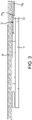
Fig. 3 is a top view ofFig. 1 illustrating the location of the sliding mount between the display and the wall. -
Fig. 4A illustrates one embodiment of the sliding mount in its extended position. -
Fig. 4B illustrates the sliding mount ofFig. 4A in its retracted or closed position. -
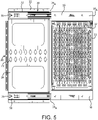
Fig. 5 is a front view of the sliding mount ofFig. 4A in its extended position. -
Fig. 6 is a front view of a removable mounting plate that attaches to the sliding mount. -
Fig. 7 is a side view of the mounting plate ofFig. 6 . -
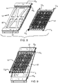
Fig. 8 is an perspective view of a sliding mount according to an embodiment of the invention with a mounting plate shown removed. -
Fig. 9 is an perspective view of the sliding mount ofFig. 8 illustrating the mounting plate in the process of being attached. -
Fig. 10 is a front view of the sliding mount attached to a monitor mounting extrusion which is attached to a wall. -
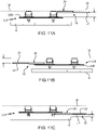
Figs. 11A -11C illustrate top views of sliding mount in different mounted locations. - As used herein, the term "wall" is intended to refer to any supporting structure upon which a monitor or video display is mounted. Similarly, the terms "monitor" and "display" are used interchangeably and are intended to broadly refer to any audio/visual display, including video monitor, flat screen television screens, electronic signs, and computer monitors.
- Referring to the drawings, several preferred embodiments of a sliding
mount assembly 10 for small devices are shown. Themount assembly 10 is intended for attachment to a wall W or other structure in a location behind a wall mounted display D, but could also be attached to the display D itself. Generally such displays are mounted in close proximity to the wall, typically about 1.5 - 5.0 inches from the wall, which is enough spacing for a conventional monitor mount to secure to the rear of the display to the wall. The small amount of spacing limits the ability to mount small components, such as power distribution, surge protection, a/v switches, video extenders, computer components (e.g., mini processors), compact PDUs, network switches, mini ampifilers, set-top boxes, splitters, streaming devices, and wireless routers, or for providing suitable cable management. In conventional systems, such equipment is generally mounted in a remote location from the display, thus requiring the routing of wires which can be costly and an eyesore. In situations where the equipment is mounted behind a display monitor, the display monitor must be removed or tilted/swung outward from the wall to access the equipment, thus requiring use of a more complex and costly monitor mount, which tends to further extend the spacing for the monitor from the wall. Also, in the latter cases, the electronics are typically mounted in wall box that must be cut into the wall, again increasing costs. - The
slide mount assembly 10 of the present invention addresses that issue. Theslide mount assembly 10 includes aslide frame 14 and a base or fixedframe 20, each of which is discussed in more detail below. A mountingplate 12 is attached to theslide frame 14 and includes mountingapertures 11, preferably arranged in a pattern, for attachment of various components/small devices. The pattern may be a universal mounting pattern sold by Middle Atlantic Products, Inc. and disclosed in US Design Patent D702,826, the disclosure of which is incorporated herein by reference in its entirety. In the illustrated embodiment, the mountingplate 12 is removably attached to aslide frame 14. In the illustrated embodiment, theslide frame 14 includes upper andlower flanges 16 which are preferably joggled outward from aslide frame plate 18. Each flange includes afirst leg 16A and asecond leg 16B, which is preferably at right angles to thefirst leg 16A and right angles to theslide frame plate 18. A plurality of spaced apart mounting apertures orslots 19 are formed in thesecond leg 16B. - In the illustrated embodiment, the mounting
plate 12 includestabs 12A that are configured to engage with theapertures 19. Preferably there are fourtabs 12A located in the corners for the mounting plate (see,Fig. 6 ). The mountingplate 12 can be attached to theslide frame 14 through any conventional means, including screws that extend through holes in one or more of the mounting tabs. However, in the illustrated embodiment (more clearly shown inFigs. 6, 7 and8 ), the mountingplate 12 preferably includes at least one disengageable locking mechanism for removably securing the mountingplate 12 to the slide frame, thereby permitting ease of access for servicing of the mounted components. In particular, at least onetab 12B on the mountingplate 12 preferably includes a Lever Lock® locking mechanism sold by Middle Atlantic Products, Inc., Fairfield, NJ and disclosed inUS Patent 9,131,622 tab 12B is inserted into the mountingaperture 19 and springs into place whentab 12B is fully inserted, thereby preventing removal. Alever 12D is attached to the locking finger and configured to move or pivot the finger away from the first position so as to move it to an unlocked (second) position where the finger is substantially behind the tab, thereby allowing the removal of thetab 12B from theslot 19. Other locking mechanisms can be use. The attachment of the mountingplate 12 on theslide frame 14 is intended to locate the surface of the mountingplate 12 as close to theslide frame plate 18 as possible so as to maximize the area for mounting components behind the display D. -
Fig. 8 illustrates the mountingplate 12 separated from theslide frame 14, with the slide frame slid onto thebase frame 20.Fig. 9 illustrates the attachment of the mountingplate 12 to theslide frame 14. Thetabs 12A on one side of the mountingplate 12 are slid completely into theapertures 19 on one of thesecond legs 16B, this provide sufficient clearance for thetabs plate 12 to be rotated toward the slide frame plate 18 (as depicted by the arrow). The mountingplate 12 is then slid downward causing thetabs apertures 19 on the othersecond leg 16B. - Referring to
Figs. 4A ,5 and10 , thebase frame 20 is configured for mounting to the wall W or other structure to which the monitor is mounted, such as a mounting extrusion or frame as discussed below. Thebase frame 20 may include an upper and/or lower mountingflange 22 that has holes for securing theflange 22 to the wall W. Alternatively or in addition, attachment holes 23 may be located at various places for securing thebase frame 20 to a wall or extrusion (see, for example,Fig. 10 which illustrates theslide mount assembly 10 attached to displaymount extrusion 100.) Theflanges 22 are preferably located on opposite sides of acenter support plate 24. - The
slide frame 14 is slidably attached to thebase frame 20. In one embodiment, the sliding attachment is provided by at least one and more preferably twoslide assemblies 30. In an embodiment, eachslide assembly 30 includes at least a fixedtrack 32 and aslide rail 34 that fits into and slides within or on thetrack 32 between a retracted position (Fig. 4B ) and an extended position (Fig. 4A ). In the illustrated embodiment, theslide rail 34 is a two piece rail assembly where afirst rail 34A acts as a track for asecond rail 34B that is nested within and slidable in relation to thefirst rail 34A, thus permitting further extension of the slide frame 14 (and, accordingly, the mounting plate 12) from thebase frame 20. Theflange 16 of theslide frame 14 is attached to thesecond rail 34B of theslide rail 34.Stops 36 on the fixed and/or slide rails limit the extension and retraction of the slide rail relative to the fixed track. - Various other mechanisms can be used for providing the sliding attachment of the
slide frame 14 to thebase frame 20 depending on the anticipated electronic components that are intended to be mounted. For example, the base frame may include a lip formed on and projecting upward from an upper edge of the base frame and the slide frame may include a u-shaped channel on its upper flange with the open end of the channel facing downward. The u-shaped channel sits on the lip so as to permit the slide frame to slide on the base frame. - As mentioned above, the fixed
frame 20 can be mounted to different structures depending on the intended need. For example, as shown inFigs 11A, 11B and 11C , the slidingmount assembly 10 can be mounted directly to a wall W - (
Fig. 11A ), or to the back (Fig. 11B ) or front (11C) of anextrusion 100 that is part of adisplay mount 110. In the illustrated embodiments, depending on theparticular display mount 110 and the location of the slidingmount assembly 10, the clearance between the sliding mount assembly and any potentially interfering structure (e.g., wall W or back of the display D), may be between 1.6 to 3.1 inches for mounting components on the sliding mount assembly. - Although the drawings and discussion refer to a side mounted laterally translating sliding mount assembly, it is also contemplated that the sliding mount assembly could be mounted bellow or above a display and move downwards or upwards, respectively. Thus, terms such as "upper" and "lower" as used herein are relative terms and used for convenience. The sliding mount assembly may include a cover or vanity plate to obscure the mounted equipment. The plate may include a keyed lock to prevent removal of the plate and access to the mounted equipment. The sliding mount assembly may be sized to accept 1U and 2U rack rail brackets for attaching larger electronic components. In addition, longer slides can be incorporated so as to permit mounting under a table or desk.
- The use of the terms "a" and "an" and "the" and similar referents in the context of describing the invention (especially in the context of the following claims) are to be construed to cover both the singular and the plural, unless otherwise indicated herein or clearly contradicted by context. The terms "comprising," "having," "including," and "containing" are to be construed as open-ended terms (i.e., meaning "including, but not limited to,") unless otherwise noted. The term "connected" is to be construed as partly or wholly contained within, attached to, or joined together, even if there is something intervening.
- The recitation of ranges of values herein are merely intended to serve as a shorthand method of referring individually to each separate value falling within the range, unless otherwise indicated herein, and each separate value is incorporated into the specification as if it were individually recited herein.
- The use of any and all examples, or exemplary language (e.g., "such as") provided herein, is intended merely to better illuminate embodiments of the invention.
- There is no intention to limit the invention to the specific form or forms disclosed, but on the contrary, the intention is to cover all modifications, alternative constructions, and equivalents falling within the appended claims. Thus, it is intended that the present invention cover the modifications and variations of this invention provided they come within the scope of the appended claims.
Claims (11)
- A slide mount assembly (10) for attachment to a wall or other structure in a location behind a mounted display and for mounting of electronics equipment, the slide mount assembly comprising:a base frame (20) configured to attach to a structure, the base frame (20) having a mounting flange with holes for use in securing the base frame to the structure;a slide frame (14) slidably attached to the base frame (20) by a sliding attachment, the sliding attachment being provided by at least one slide assembly (30), the slide frame including upper and lower flanges (16) which are attached to or formed integral with a slide frame plate (18), each flange having a plurality of spaced apart mounting apertures (19); anda mounting plate (12) attached to the slide frame (14), the mounting plate having a generally planar portion with a plurality of mounting apertures (11), the planar portion having upper and lower edges, at least one mounting tab (12A) is formed on and extends outward from each of the upper and lower edges of the mounting plate (12), each mounting tab being configured to engage with one of the mounting apertures (19) on the slide frame (14);characterized by the upper and lower flanges (16) of the slide frame (14) being joggled outward from the slide frame plate (18), with each flange including a first leg (16A) and a second leg (16B), the first leg (16A) being offset from the slide frame plate (18) and at a right angle to the second leg (16B) which is at a right angle to the slide frame plate (18); and wherein the mounting apertures (19) on the flange (16) of the slide frame (14) are formed in the second leg (16B).
- The slide mount assembly according to claim 1, wherein there are four tabs (12A, 12B), one located at each corner of the mounting plate (12).
- The slide mount assembly according to either claim 1 or 2, wherein the mounting plate (12) is removably attached to the slide frame (14) and wherein at least one of tabs (12B) includes a disengageable locking mechanism for removably securing the tab (12B) to the slide frame (14).
- The slide mount assembly according to claim 3, wherein the locking mechanism includes a locking finger (12C) that is movable between a first position where the finger (12C) protrudes laterally from the tab (12B) and a second position wherein the finger (12C) is located substantially under the tab (12B), and wherein in the first position, the finger (12C) in combination with the tab (12B) inhibits removal of the tab (12B) from the mounting aperture (19) in the slide frame (14) and wherein in the second position, the finger (12C) does not prevent removal of the tab (12B) from the mounting aperture (19) in the slide frame
- The slide mount assembly according to claim 4, wherein the locking finger (12c) is biased into the first position.
- The slide mount assembly according to either claim 4 or 5, further comprising a lever (12D) attached to the locking finger (12C) for permitting the locking finger (12C) to be moved into the second position.
- The slide mount assembly according to any of the preceding claims, wherein the slide assembly comprises by two slide assemblies (30) spaced apart from one another, one of the slide assemblies (30) mounted to the upper flange (16) of the slide frame (14) and a top portion of the base frame (20), and the other of the slide assemblies (30) mounted to the lower flange (16) of the slide frame (14) and a bottom portion of the base frame (20).
- The slide mount assembly according to claim 7, wherein each slide assembly (30) includes at least a fixed track (32) and a slide rail (34), the slide rail (34) engaged with and sliding within or upon the fixed track (32) between a retracted position where the slide rail (34) substantially overlies the fixed track (32), and an extended position where the slide rail (34) is slid at least partially away from the fixed track (32) so as to be cantilevered off of the fixed track (32).
- The slide mount assembly according to claim 8, wherein the slide rail (34) comprises a two piece rail assembly with a first rail (34) sliding on and engaged with the fixed track (32), and a second rail (34B) that slides on and is engaged with the first rail (34A) and is attached to the associated flange on the slide frame (14).
- The slide mount assembly according to any of claims 1-6, wherein the slide assembly (30) comprises a lip formed on and projecting upward from an upper edge of the base frame and a u-shaped channel on the upper flange (16) of the slide frame (14) with an open end of the channel facing downward, and wherein the u-shaped channel sits on the lip so as to permit the slide frame to slide on the base frame.
- The slide mount assembly according to either claim 7 or 8, further comprising stops (36) attached to the fixed track (32) or the slide rail (34) for limiting the extension and retraction of the slide rail (34) relative to the fixed track (32).
Applications Claiming Priority (3)
| Application Number | Priority Date | Filing Date | Title |
|---|---|---|---|
| US201762517583P | 2017-06-09 | 2017-06-09 | |
| US16/001,700 US10508766B2 (en) | 2017-06-09 | 2018-06-06 | Wall mounted sliding mount for small devices |
| PCT/US2018/036495 WO2018226983A1 (en) | 2017-06-09 | 2018-06-07 | Wall mounted sliding mount for small devices |
Publications (3)
| Publication Number | Publication Date |
|---|---|
| EP3635289A1 EP3635289A1 (en) | 2020-04-15 |
| EP3635289A4 EP3635289A4 (en) | 2020-12-09 |
| EP3635289B1 true EP3635289B1 (en) | 2022-06-01 |
Family
ID=64562311
Family Applications (1)
| Application Number | Title | Priority Date | Filing Date |
|---|---|---|---|
| EP18813259.1A Active EP3635289B1 (en) | 2017-06-09 | 2018-06-07 | Wall mounted sliding mount for small devices |
Country Status (3)
| Country | Link |
|---|---|
| US (1) | US10508766B2 (en) |
| EP (1) | EP3635289B1 (en) |
| WO (1) | WO2018226983A1 (en) |
Families Citing this family (4)
| Publication number | Priority date | Publication date | Assignee | Title |
|---|---|---|---|---|
| US10104963B2 (en) * | 2013-06-07 | 2018-10-23 | Milestone Av Technologies Llc | Wall mount system |
| CN111820598A (en) * | 2020-07-14 | 2020-10-27 | 德州学院 | A computer lifting device |
| CN112043095A (en) * | 2020-08-28 | 2020-12-08 | 广州富港万嘉智能科技有限公司 | Equipment module placing structure |
| US11940088B2 (en) * | 2021-08-20 | 2024-03-26 | Rahi Systems Inc. | Universal hardware mount |
Family Cites Families (41)
| Publication number | Priority date | Publication date | Assignee | Title |
|---|---|---|---|---|
| US5227582A (en) * | 1992-04-06 | 1993-07-13 | Digital Equipment Corporation | Video amplifier assembly mount |
| CN100404768C (en) | 2003-09-26 | 2008-07-23 | Thk株式会社 | wall mount |
| US7604481B2 (en) * | 2004-01-16 | 2009-10-20 | Meadwestvaco Corporation | White board and white board display system |
| USD590184S1 (en) * | 2006-03-22 | 2009-04-14 | Alfred Barabas | Mount for a digital media player |
| US20080029669A1 (en) * | 2006-08-01 | 2008-02-07 | Rbw Industries, Inc. | Flat Screen TV Bracket For A Vehicle |
| US7963489B2 (en) | 2006-08-10 | 2011-06-21 | Peerless Industries, Inc. | Extension mechanism for a mounting system |
| TWM351297U (en) * | 2008-08-07 | 2009-02-21 | Aopen Inc | Display hanging rack and assembly of display hanging rack and electronic device |
| US20100288895A1 (en) * | 2009-05-13 | 2010-11-18 | Steven Shamie | Universal holder and flexible member for mounting, holding, and adjustably positioning electronic products and accessories |
| US8926029B2 (en) * | 2009-06-29 | 2015-01-06 | Evans Consoles Corporation | Console having cabinet and support structure |
| US20110011993A1 (en) * | 2009-07-17 | 2011-01-20 | Aopen Incorporated | Rail-type support device |
| US8596600B2 (en) * | 2009-08-20 | 2013-12-03 | Maya Design, Inc. | Collaborative panel system |
| US8333355B2 (en) * | 2010-02-12 | 2012-12-18 | Peerless Industries, Inc. | Adjustable display mount |
| US8724037B1 (en) * | 2010-06-04 | 2014-05-13 | Kurt William Massey | Mounting system |
| US9121543B2 (en) * | 2010-06-28 | 2015-09-01 | Milestone Av Technologies Llc | Swing arm, tilt positionable mount for electronic display |
| US8550415B2 (en) * | 2010-10-29 | 2013-10-08 | Bell'o International Corp. | Adjustable flat panel display mounting system |
| US10039201B2 (en) * | 2011-10-21 | 2018-07-31 | Innovelis, Inc. | Mounting systems for digital media players |
| US9131622B2 (en) | 2011-06-03 | 2015-09-08 | Middle Atlantic Products, Inc. | Rack rail locking lever |
| GB2494139A (en) * | 2011-08-31 | 2013-03-06 | Piixl Technologies Ltd | Flat panel mounting apparatus having a bracket to receive another device |
| US20130069507A1 (en) * | 2011-09-15 | 2013-03-21 | James Dowling | Method and device for wall mounting flat panel monitor and storing associated audio/video components |
| CN103999013B (en) * | 2011-10-14 | 2017-04-05 | 爱格升有限公司 | Flat board installing arm system and method |
| US8939417B1 (en) * | 2014-04-24 | 2015-01-27 | Innovelis, Inc. | Mounting systems for electronic devices |
| EP2793652B1 (en) | 2011-12-19 | 2018-08-15 | Hidden View Oy | An arrangement for fastening elements to a wall |
| US9146001B2 (en) | 2012-02-01 | 2015-09-29 | Peerless Industries, Inc. | Endcap mounting system for mounting audio/visual devices or the like |
| USD702826S1 (en) | 2012-02-22 | 2014-04-15 | Middle Atlantic Products, Inc. | Electronics mounting plate with a universal hole pattern |
| TWI524771B (en) * | 2012-08-14 | 2016-03-01 | 建碁股份有限公司 | Monitor supporting module |
| US20140061406A1 (en) * | 2012-09-06 | 2014-03-06 | Eddy Nelson Chevalier | System for attaching accessories to a monitor |
| USD695748S1 (en) * | 2013-01-14 | 2013-12-17 | Crystal Morris | Portable electronics tray |
| US9765923B2 (en) * | 2013-10-09 | 2017-09-19 | Milestone Av Technologies Llc | Cleat mount with visual and audible indicator |
| US9366275B2 (en) * | 2013-10-19 | 2016-06-14 | Russ Bassett Corporation | Slatwall clamp |
| EP3766381A1 (en) * | 2014-03-05 | 2021-01-20 | Beanius, L.L.C. | System for mounting, accessing, moving and folding away articles on, under or along a surface |
| US10244862B2 (en) * | 2014-03-31 | 2019-04-02 | Eric Gallup | Bendable strap with detachable accessory |
| TWI547172B (en) * | 2014-09-03 | 2016-08-21 | 鴻海精密工業股份有限公司 | Mounting apparatus for screens |
| USD759005S1 (en) * | 2014-11-10 | 2016-06-14 | Kenji Murakami | Cellular phone holder |
| US9265346B1 (en) * | 2015-03-13 | 2016-02-23 | Anthony Eugene Forney | Responsive support system and mount |
| US9538833B2 (en) * | 2016-01-13 | 2017-01-10 | Donald Lee Rowley | Assembly for storing and deploying for use a handheld digital device |
| US9648771B1 (en) * | 2016-03-31 | 2017-05-09 | Middle Atlantic Products, Inc. | Multi-piece rack shelf |
| US10064489B2 (en) * | 2016-04-13 | 2018-09-04 | Twin-Star International, Inc. | Flat panel display wall mounting system |
| US10117344B2 (en) * | 2017-02-04 | 2018-10-30 | Innovelis, Inc. | Mounting systems for media players |
| US10194544B2 (en) * | 2017-02-04 | 2019-01-29 | Innovelis, Inc. | Mounting systems for media players |
| DE102018101210B4 (en) * | 2018-01-19 | 2019-08-22 | Fujitsu Client Computing Limited | Wall mounting for an electronic display, computer assembly and method of mounting an electronic display and a computer system to a wall |
| US20190277442A1 (en) * | 2018-03-09 | 2019-09-12 | Ilya Kandibur | Accessory holder for a wall mounted tv |
-
2018
- 2018-06-06 US US16/001,700 patent/US10508766B2/en active Active
- 2018-06-07 WO PCT/US2018/036495 patent/WO2018226983A1/en not_active Ceased
- 2018-06-07 EP EP18813259.1A patent/EP3635289B1/en active Active
Also Published As
| Publication number | Publication date |
|---|---|
| WO2018226983A1 (en) | 2018-12-13 |
| EP3635289A1 (en) | 2020-04-15 |
| US20180352956A1 (en) | 2018-12-13 |
| EP3635289A4 (en) | 2020-12-09 |
| US10508766B2 (en) | 2019-12-17 |
Similar Documents
| Publication | Publication Date | Title |
|---|---|---|
| US10508766B2 (en) | Wall mounted sliding mount for small devices | |
| US8459756B2 (en) | Adjustable blanking panel | |
| US7963489B2 (en) | Extension mechanism for a mounting system | |
| US7065933B2 (en) | Trim piece, a trim piece mounting arrangement and a method of mounting a trim piece for an electronic equipment cabinet | |
| US9148006B2 (en) | Interchangeable base system | |
| US6580602B2 (en) | Computer in a wall | |
| US20050183353A1 (en) | Multi-media workstation having a master rail system | |
| US9408465B2 (en) | Method and device for wall mounting flat panel monitor and storing associated audio/video components | |
| TWI501020B (en) | Mounting system | |
| US5897178A (en) | Computer housing mounting system | |
| US10512327B2 (en) | Furniture with pivotable electronics rack | |
| US7878473B1 (en) | Multi-functioning mount system for a monitor | |
| EP2449866A2 (en) | Adjustable vertical exhaust duct | |
| US20110101179A1 (en) | Tv support structure with latching mechanism | |
| US20060039121A1 (en) | Detachable case assembly for computer server | |
| US20130069507A1 (en) | Method and device for wall mounting flat panel monitor and storing associated audio/video components | |
| US7665255B2 (en) | Cable distribution and management system | |
| US20140233205A1 (en) | Mounting apparatus | |
| US20010013420A1 (en) | Elements to cover cables, cases, shells, panels, and channel to cover cables, particularly for electric and/or electronic apparatuses used on a working plane and like or on a floor | |
| US7296523B1 (en) | Space-saving mounting table for use with an equipment rack | |
| WO2025072974A1 (en) | Modular mounting system for televisions and associated equipment | |
| US20260117922A1 (en) | In-wall mounting system for flat panel televisions | |
| WO2025166381A1 (en) | Projector screen roller mount system | |
| GB2410144A (en) | Television mounting apparatus | |
| GB2289557A (en) | Personal computer enclosures |
Legal Events
| Date | Code | Title | Description |
|---|---|---|---|
| STAA | Information on the status of an ep patent application or granted ep patent |
Free format text: STATUS: THE INTERNATIONAL PUBLICATION HAS BEEN MADE |
|
| PUAI | Public reference made under article 153(3) epc to a published international application that has entered the european phase |
Free format text: ORIGINAL CODE: 0009012 |
|
| STAA | Information on the status of an ep patent application or granted ep patent |
Free format text: STATUS: REQUEST FOR EXAMINATION WAS MADE |
|
| 17P | Request for examination filed |
Effective date: 20191017 |
|
| AK | Designated contracting states |
Kind code of ref document: A1 Designated state(s): AL AT BE BG CH CY CZ DE DK EE ES FI FR GB GR HR HU IE IS IT LI LT LU LV MC MK MT NL NO PL PT RO RS SE SI SK SM TR |
|
| AX | Request for extension of the european patent |
Extension state: BA ME |
|
| DAV | Request for validation of the european patent (deleted) | ||
| DAX | Request for extension of the european patent (deleted) | ||
| A4 | Supplementary search report drawn up and despatched |
Effective date: 20201111 |
|
| RIC1 | Information provided on ipc code assigned before grant |
Ipc: F16M 11/04 20060101AFI20201105BHEP Ipc: B60R 11/00 20060101ALI20201105BHEP Ipc: B60R 11/02 20060101ALI20201105BHEP Ipc: F16M 11/18 20060101ALI20201105BHEP Ipc: A47B 81/06 20060101ALI20201105BHEP Ipc: F16M 13/02 20060101ALI20201105BHEP Ipc: A47B 47/05 20060101ALI20201105BHEP |
|
| RIN1 | Information on inventor provided before grant (corrected) |
Inventor name: GEBRIL, MOHAMED Inventor name: ALOSIO, ROBERT Inventor name: HARRIS, ARTUR D., JR. |
|
| GRAP | Despatch of communication of intention to grant a patent |
Free format text: ORIGINAL CODE: EPIDOSNIGR1 |
|
| STAA | Information on the status of an ep patent application or granted ep patent |
Free format text: STATUS: GRANT OF PATENT IS INTENDED |
|
| INTG | Intention to grant announced |
Effective date: 20220104 |
|
| GRAA | (expected) grant |
Free format text: ORIGINAL CODE: 0009210 |
|
| GRAS | Grant fee paid |
Free format text: ORIGINAL CODE: EPIDOSNIGR3 |
|
| STAA | Information on the status of an ep patent application or granted ep patent |
Free format text: STATUS: THE PATENT HAS BEEN GRANTED |
|
| AK | Designated contracting states |
Kind code of ref document: B1 Designated state(s): AL AT BE BG CH CY CZ DE DK EE ES FI FR GB GR HR HU IE IS IT LI LT LU LV MC MK MT NL NO PL PT RO RS SE SI SK SM TR |
|
| REG | Reference to a national code |
Ref country code: GB Ref legal event code: FG4D |
|
| REG | Reference to a national code |
Ref country code: AT Ref legal event code: REF Ref document number: 1495587 Country of ref document: AT Kind code of ref document: T Effective date: 20220615 Ref country code: CH Ref legal event code: EP Ref country code: DE Ref legal event code: R096 Ref document number: 602018036304 Country of ref document: DE |
|
| REG | Reference to a national code |
Ref country code: IE Ref legal event code: FG4D |
|
| REG | Reference to a national code |
Ref country code: NL Ref legal event code: FP |
|
| REG | Reference to a national code |
Ref country code: LT Ref legal event code: MG9D |
|
| PG25 | Lapsed in a contracting state [announced via postgrant information from national office to epo] |
Ref country code: SE Free format text: LAPSE BECAUSE OF FAILURE TO SUBMIT A TRANSLATION OF THE DESCRIPTION OR TO PAY THE FEE WITHIN THE PRESCRIBED TIME-LIMIT Effective date: 20220601 Ref country code: NO Free format text: LAPSE BECAUSE OF FAILURE TO SUBMIT A TRANSLATION OF THE DESCRIPTION OR TO PAY THE FEE WITHIN THE PRESCRIBED TIME-LIMIT Effective date: 20220901 Ref country code: LT Free format text: LAPSE BECAUSE OF FAILURE TO SUBMIT A TRANSLATION OF THE DESCRIPTION OR TO PAY THE FEE WITHIN THE PRESCRIBED TIME-LIMIT Effective date: 20220601 Ref country code: HR Free format text: LAPSE BECAUSE OF FAILURE TO SUBMIT A TRANSLATION OF THE DESCRIPTION OR TO PAY THE FEE WITHIN THE PRESCRIBED TIME-LIMIT Effective date: 20220601 Ref country code: GR Free format text: LAPSE BECAUSE OF FAILURE TO SUBMIT A TRANSLATION OF THE DESCRIPTION OR TO PAY THE FEE WITHIN THE PRESCRIBED TIME-LIMIT Effective date: 20220902 Ref country code: FI Free format text: LAPSE BECAUSE OF FAILURE TO SUBMIT A TRANSLATION OF THE DESCRIPTION OR TO PAY THE FEE WITHIN THE PRESCRIBED TIME-LIMIT Effective date: 20220601 Ref country code: ES Free format text: LAPSE BECAUSE OF FAILURE TO SUBMIT A TRANSLATION OF THE DESCRIPTION OR TO PAY THE FEE WITHIN THE PRESCRIBED TIME-LIMIT Effective date: 20220601 Ref country code: BG Free format text: LAPSE BECAUSE OF FAILURE TO SUBMIT A TRANSLATION OF THE DESCRIPTION OR TO PAY THE FEE WITHIN THE PRESCRIBED TIME-LIMIT Effective date: 20220901 |
|
| REG | Reference to a national code |
Ref country code: AT Ref legal event code: MK05 Ref document number: 1495587 Country of ref document: AT Kind code of ref document: T Effective date: 20220601 |
|
| PG25 | Lapsed in a contracting state [announced via postgrant information from national office to epo] |
Ref country code: RS Free format text: LAPSE BECAUSE OF FAILURE TO SUBMIT A TRANSLATION OF THE DESCRIPTION OR TO PAY THE FEE WITHIN THE PRESCRIBED TIME-LIMIT Effective date: 20220601 Ref country code: PL Free format text: LAPSE BECAUSE OF FAILURE TO SUBMIT A TRANSLATION OF THE DESCRIPTION OR TO PAY THE FEE WITHIN THE PRESCRIBED TIME-LIMIT Effective date: 20220601 Ref country code: LV Free format text: LAPSE BECAUSE OF FAILURE TO SUBMIT A TRANSLATION OF THE DESCRIPTION OR TO PAY THE FEE WITHIN THE PRESCRIBED TIME-LIMIT Effective date: 20220601 |
|
| PG25 | Lapsed in a contracting state [announced via postgrant information from national office to epo] |
Ref country code: SM Free format text: LAPSE BECAUSE OF FAILURE TO SUBMIT A TRANSLATION OF THE DESCRIPTION OR TO PAY THE FEE WITHIN THE PRESCRIBED TIME-LIMIT Effective date: 20220601 Ref country code: SK Free format text: LAPSE BECAUSE OF FAILURE TO SUBMIT A TRANSLATION OF THE DESCRIPTION OR TO PAY THE FEE WITHIN THE PRESCRIBED TIME-LIMIT Effective date: 20220601 Ref country code: RO Free format text: LAPSE BECAUSE OF FAILURE TO SUBMIT A TRANSLATION OF THE DESCRIPTION OR TO PAY THE FEE WITHIN THE PRESCRIBED TIME-LIMIT Effective date: 20220601 Ref country code: PT Free format text: LAPSE BECAUSE OF FAILURE TO SUBMIT A TRANSLATION OF THE DESCRIPTION OR TO PAY THE FEE WITHIN THE PRESCRIBED TIME-LIMIT Effective date: 20221003 Ref country code: EE Free format text: LAPSE BECAUSE OF FAILURE TO SUBMIT A TRANSLATION OF THE DESCRIPTION OR TO PAY THE FEE WITHIN THE PRESCRIBED TIME-LIMIT Effective date: 20220601 Ref country code: CZ Free format text: LAPSE BECAUSE OF FAILURE TO SUBMIT A TRANSLATION OF THE DESCRIPTION OR TO PAY THE FEE WITHIN THE PRESCRIBED TIME-LIMIT Effective date: 20220601 Ref country code: AT Free format text: LAPSE BECAUSE OF FAILURE TO SUBMIT A TRANSLATION OF THE DESCRIPTION OR TO PAY THE FEE WITHIN THE PRESCRIBED TIME-LIMIT Effective date: 20220601 |
|
| REG | Reference to a national code |
Ref country code: CH Ref legal event code: PL |
|
| REG | Reference to a national code |
Ref country code: BE Ref legal event code: MM Effective date: 20220630 |
|
| PG25 | Lapsed in a contracting state [announced via postgrant information from national office to epo] |
Ref country code: MC Free format text: LAPSE BECAUSE OF FAILURE TO SUBMIT A TRANSLATION OF THE DESCRIPTION OR TO PAY THE FEE WITHIN THE PRESCRIBED TIME-LIMIT Effective date: 20220601 Ref country code: IS Free format text: LAPSE BECAUSE OF FAILURE TO SUBMIT A TRANSLATION OF THE DESCRIPTION OR TO PAY THE FEE WITHIN THE PRESCRIBED TIME-LIMIT Effective date: 20221001 |
|
| REG | Reference to a national code |
Ref country code: DE Ref legal event code: R097 Ref document number: 602018036304 Country of ref document: DE |
|
| PG25 | Lapsed in a contracting state [announced via postgrant information from national office to epo] |
Ref country code: AL Free format text: LAPSE BECAUSE OF FAILURE TO SUBMIT A TRANSLATION OF THE DESCRIPTION OR TO PAY THE FEE WITHIN THE PRESCRIBED TIME-LIMIT Effective date: 20220601 |
|
| PLBE | No opposition filed within time limit |
Free format text: ORIGINAL CODE: 0009261 |
|
| STAA | Information on the status of an ep patent application or granted ep patent |
Free format text: STATUS: NO OPPOSITION FILED WITHIN TIME LIMIT |
|
| PG25 | Lapsed in a contracting state [announced via postgrant information from national office to epo] |
Ref country code: LU Free format text: LAPSE BECAUSE OF NON-PAYMENT OF DUE FEES Effective date: 20220607 Ref country code: LI Free format text: LAPSE BECAUSE OF NON-PAYMENT OF DUE FEES Effective date: 20220630 Ref country code: IE Free format text: LAPSE BECAUSE OF NON-PAYMENT OF DUE FEES Effective date: 20220607 Ref country code: DK Free format text: LAPSE BECAUSE OF FAILURE TO SUBMIT A TRANSLATION OF THE DESCRIPTION OR TO PAY THE FEE WITHIN THE PRESCRIBED TIME-LIMIT Effective date: 20220601 Ref country code: CH Free format text: LAPSE BECAUSE OF NON-PAYMENT OF DUE FEES Effective date: 20220630 |
|
| 26N | No opposition filed |
Effective date: 20230302 |
|
| PG25 | Lapsed in a contracting state [announced via postgrant information from national office to epo] |
Ref country code: SI Free format text: LAPSE BECAUSE OF FAILURE TO SUBMIT A TRANSLATION OF THE DESCRIPTION OR TO PAY THE FEE WITHIN THE PRESCRIBED TIME-LIMIT Effective date: 20220601 Ref country code: BE Free format text: LAPSE BECAUSE OF NON-PAYMENT OF DUE FEES Effective date: 20220630 |
|
| PG25 | Lapsed in a contracting state [announced via postgrant information from national office to epo] |
Ref country code: IT Free format text: LAPSE BECAUSE OF FAILURE TO SUBMIT A TRANSLATION OF THE DESCRIPTION OR TO PAY THE FEE WITHIN THE PRESCRIBED TIME-LIMIT Effective date: 20220601 |
|
| PG25 | Lapsed in a contracting state [announced via postgrant information from national office to epo] |
Ref country code: MK Free format text: LAPSE BECAUSE OF FAILURE TO SUBMIT A TRANSLATION OF THE DESCRIPTION OR TO PAY THE FEE WITHIN THE PRESCRIBED TIME-LIMIT Effective date: 20220601 Ref country code: CY Free format text: LAPSE BECAUSE OF FAILURE TO SUBMIT A TRANSLATION OF THE DESCRIPTION OR TO PAY THE FEE WITHIN THE PRESCRIBED TIME-LIMIT Effective date: 20220601 |
|
| PG25 | Lapsed in a contracting state [announced via postgrant information from national office to epo] |
Ref country code: HU Free format text: LAPSE BECAUSE OF FAILURE TO SUBMIT A TRANSLATION OF THE DESCRIPTION OR TO PAY THE FEE WITHIN THE PRESCRIBED TIME-LIMIT; INVALID AB INITIO Effective date: 20180607 |
|
| PG25 | Lapsed in a contracting state [announced via postgrant information from national office to epo] |
Ref country code: TR Free format text: LAPSE BECAUSE OF FAILURE TO SUBMIT A TRANSLATION OF THE DESCRIPTION OR TO PAY THE FEE WITHIN THE PRESCRIBED TIME-LIMIT Effective date: 20220601 |
|
| PG25 | Lapsed in a contracting state [announced via postgrant information from national office to epo] |
Ref country code: MT Free format text: LAPSE BECAUSE OF FAILURE TO SUBMIT A TRANSLATION OF THE DESCRIPTION OR TO PAY THE FEE WITHIN THE PRESCRIBED TIME-LIMIT Effective date: 20220601 |
|
| PG25 | Lapsed in a contracting state [announced via postgrant information from national office to epo] |
Ref country code: BG Free format text: LAPSE BECAUSE OF FAILURE TO SUBMIT A TRANSLATION OF THE DESCRIPTION OR TO PAY THE FEE WITHIN THE PRESCRIBED TIME-LIMIT Effective date: 20220601 |
|
| PG25 | Lapsed in a contracting state [announced via postgrant information from national office to epo] |
Ref country code: BG Free format text: LAPSE BECAUSE OF FAILURE TO SUBMIT A TRANSLATION OF THE DESCRIPTION OR TO PAY THE FEE WITHIN THE PRESCRIBED TIME-LIMIT Effective date: 20220601 |
|
| PGFP | Annual fee paid to national office [announced via postgrant information from national office to epo] |
Ref country code: NL Payment date: 20250409 Year of fee payment: 8 |
|
| PGFP | Annual fee paid to national office [announced via postgrant information from national office to epo] |
Ref country code: DE Payment date: 20250402 Year of fee payment: 8 |
|
| PGFP | Annual fee paid to national office [announced via postgrant information from national office to epo] |
Ref country code: GB Payment date: 20250401 Year of fee payment: 8 |
|
| PGFP | Annual fee paid to national office [announced via postgrant information from national office to epo] |
Ref country code: FR Payment date: 20250401 Year of fee payment: 8 |