EP3634806B1 - A device for positioning a lighting body - Google Patents
A device for positioning a lighting body Download PDFInfo
- Publication number
- EP3634806B1 EP3634806B1 EP18742594.7A EP18742594A EP3634806B1 EP 3634806 B1 EP3634806 B1 EP 3634806B1 EP 18742594 A EP18742594 A EP 18742594A EP 3634806 B1 EP3634806 B1 EP 3634806B1
- Authority
- EP
- European Patent Office
- Prior art keywords
- light module
- positioning
- lighting body
- threaded section
- actuator
- Prior art date
- Legal status (The legal status is an assumption and is not a legal conclusion. Google has not performed a legal analysis and makes no representation as to the accuracy of the status listed.)
- Active
Links
Images

Classifications
-
- B—PERFORMING OPERATIONS; TRANSPORTING
- B60—VEHICLES IN GENERAL
- B60Q—ARRANGEMENT OF SIGNALLING OR LIGHTING DEVICES, THE MOUNTING OR SUPPORTING THEREOF OR CIRCUITS THEREFOR, FOR VEHICLES IN GENERAL
- B60Q1/00—Arrangement of optical signalling or lighting devices, the mounting or supporting thereof or circuits therefor
- B60Q1/02—Arrangement of optical signalling or lighting devices, the mounting or supporting thereof or circuits therefor the devices being primarily intended to illuminate the way ahead or to illuminate other areas of way or environments
- B60Q1/04—Arrangement of optical signalling or lighting devices, the mounting or supporting thereof or circuits therefor the devices being primarily intended to illuminate the way ahead or to illuminate other areas of way or environments the devices being headlights
- B60Q1/06—Arrangement of optical signalling or lighting devices, the mounting or supporting thereof or circuits therefor the devices being primarily intended to illuminate the way ahead or to illuminate other areas of way or environments the devices being headlights adjustable, e.g. remotely-controlled from inside vehicle
- B60Q1/068—Arrangement of optical signalling or lighting devices, the mounting or supporting thereof or circuits therefor the devices being primarily intended to illuminate the way ahead or to illuminate other areas of way or environments the devices being headlights adjustable, e.g. remotely-controlled from inside vehicle by mechanical means
- B60Q1/0683—Adjustable by rotation of a screw
Definitions
- the present invention refers to a device for positioning a lighting body, in particular a lighting body of a vehicle, such as a headlamp, a fog lamp and similar.
- a device for positioning a lighting body of the aforementioned kind has been disclosed in the patent No. EP 1 739 346 B1 , for instance.
- Said device cooperates with the lens holder for pivoting the lens holder along an adjusting axis of the device.
- the positioning device is selected as an endless screw type adjusting screw extending vertically, where the source, the lens, the holder and the part are integrated in the case.
- Said adjusting screw cooperates with a tongue provided with a thread by means of which either the case or the light source can be adjusted.
- a drawback of the disclosed solution lies in the tongue, which is moved along a circular arc together with the case to be adjusted.
- DE 10 2012 111 311 A1 describes a device for positioning a lighting body comprising a case with an articulated light module arranged therein, said module being rotatable about the centreline thereof which extends approximately horizontally and/or approximately perpendicularly to the direction of the luminous flux, and a device for positioning the light module, wherein the device for positioning the light module with respect to a horizontal centreline of the lighting body and, respectively, with regard to the ideal direction of the luminous flux is arrangeable on said case, said device for positioning the light module is formed of at least two actuators set at an angle with respect to each other and mutually cooperating, and a follower associated with said light module, wherein said follower is formed with a fork-like structure comprising threaded plates that extend mutually in parallel and are spaced with regard to each other and are attached at the first end thereof to a base of the follower, said threaded plates being formed in the region of cooperation with a threaded section of the actuator with a threaded section, which comprises an internal thread provided
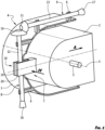
- a lighting body of a vehicle shown schematically in Fig. 1 comprises a case 1 with an articulated light module 2 arranged therein, such as a light source, a reflector of the lighting body, and similar.
- Said module 2 is rotatable about the centreline 3 thereof which, in the present embodiment, extends approximately horizontally and/or approximately perpendicularly to the direction A of the luminous flux.
- a device 4 for positioning the light module 2 with respect to a horizontal centreline 5 of the lighting body and, respectively, with regard to the ideal direction A of the luminous flux is arranged on the case 1.
- Said device 4 for positioning the light module 2 is fixed by means of fixing means 6, wherein it cooperates simultaneously with a follower 7 associated with said light module 2.
- Said follower 7 can be formed either as an integral part of the light module 2, or as a separate element which is attached to the light module 2 in a manner known per se.
- Said device 4 for positioning the light module 2 is connected with said follower 7 by means of a force-locking joint and/or a form-locking joint.
- Said device 4 for positioning the light module 2 is formed of at least two actuators 8, 9 and said follower 7, wherein said actuators 8, 9 are set at an angle to each other and cooperate with each other, and wherein each actuator 8, 9 comprises at the place of the cooperation with the opposite actuator 9, 8 a transfer means 10, 11 mating with each other.
- Said transfer means 10, 11 are provided for transfer of motion from the first actuator 8 and, respectively, 9 to the second actuator 9 and, respectively, 8, the transfer means 10, 11 being selected in the present embodiment as a pair of bevelled gears 10, 11, for example.
- each actuator 8, 9 comprises a stem 12, 13 extending away from each transfer means 10, 11 in direction towards at least one free end of the lighting body according to the invention.
- Said actuators 8, 9 are fixed by means of the connection of the fixing means 6 with the stem 12, 13, wherein a rotational movement of the actuator 8, 9 about the centreline thereof is enabled in each fixing means 6.
- transfer of the rotational movement from the first actuator 8 and, respectively, 9 to the second actuator 9 and, respectively, 8 is achieved via the transfer means 10, 11.
- At least part of the stem 12, 13 of at least one of the actuators 8, 9 is formed in the region of the two neighbouring fixing means 6 with a threaded section 14 provided for mating and cooperating with said follower 7. The length of said threaded section 14 exceeds the dimension of the follower 7 in direction of the extension of the stem 12, 13 of the actuator 8, 9.
- each actuator 8, 9 is formed with a projection and/or a depression 16, 17 for engaging a tool to enter a torque into at least one of the actuators 8, 9.
- at least one end of the actuator 8, 9 provided with the transfer means 10, 11 is additionally formed with a projection and/or a depression for engaging a tool to enter a torque into at least one of the actuators 8, 9.
- Said follower 7 is either an integral part of the light module 2, or is associated with the latter in a removable manner.
- the follower 7 is formed with a fork-like structure 18 comprising threaded plates 19, 20 that extend mutually in parallel and are spaced with regard to each other.
- said threaded plates 19, 20 extend in parallel also with at least one of the actuators 8, 9, in the present embodiment with the actuator 8, wherein they extend substantially beyond the centreline of the stem of the actuator 8.
- Said threaded plates 19, 20 are attached at the first end thereof to a base 21 of the follower 7, which is further either separably or permanently associated with the light module 2.
- each threaded plate 19, 20 is formed in the area of the free end thereof and at the sides facing each other with a chamfer 22, which facilitates placing the actuator 8 and, respectively, 9 between the threaded plates 19, 20.
- the threaded plates 19, 20 are formed in the region of cooperation with the threaded section 14 of the actuator 8 and, respectively, 9 with a threaded section 22 comprising an internal thread 23 provided for cooperation with an external thread 24 of the threaded section 14.
- Said thread 23, 24 is preferably selected as a fine thread.
- Said threaded section 22 comprising the internal thread 23 is formed on an arc 25, the centreline thereof approximately corresponds to the horizontal centreline 5 of the lighting body and, respectively, the light module 2, the latter is to be rotated about.
- Said arc 25 lies in a vertical plane extending through the centreline of the threaded section 14 and, respectively, the actuator 8, and in parallel with the fork-like structure 18 and, respectively, in parallel with the threaded plates 19, 20.
- said threaded section 22, which is provided in the fork-like structure 18, is formed in a manner to compensate movements over the circular arc 25 and ensures, in each position of the fork-like structure 18 relative to the actuator 8, a constant contact in several threads between the outer thread 24 of the threaded section 14 and the inner thread 23 of the fork-like structure 18 within the required positioning region of the lighting module 2.
- Said device 4 for positioning the light module 2 provides for the lighting module 2 to be positioned in the case 1 of the lighting body 2, thus protecting the elements of the lighting body against the overload in the terminal positioning region. Said protection is achieved in a manner, that said shifting section 15 which is associated with each end of the threaded section 14 is pushed, in each extreme rotated position of the fork-like structure 18 and with continuous entering of torque into the actuator 8, between the threaded plates 19, 20. Since the radial dimension of the shifting section 15 is greater than the radial dimension of the threaded section 14 and, therefore, greater than the spacing between the threaded plates 19, 20, said shifting section 15 pushes the threaded plates 19, 20 apart.
Landscapes
- Engineering & Computer Science (AREA)
- Mechanical Engineering (AREA)
- Lighting Device Outwards From Vehicle And Optical Signal (AREA)
- Non-Portable Lighting Devices Or Systems Thereof (AREA)
Description
- The present invention refers to a device for positioning a lighting body, in particular a lighting body of a vehicle, such as a headlamp, a fog lamp and similar.
- A device for positioning a lighting body of the aforementioned kind has been disclosed in the patent No.
EP 1 739 346 B1
DE 10 2012 111 311 A1
Further prior art is known fromEP 2 650 173 A1 - It is the object of the present invention to create a device for positioning a lighting body which remedies drawbacks of the known solution.
- According to the present invention, the object as set above is solved by features set forth in the characterising part of
claim 1. Detail of the invention is disclosed in respective subclaims. - The invention is further described in detail by way of non-limiting embodiment, and with a reference to the accompanying drawings, where
- Fig. 1
- shows a partial section in the vertical plane of a lighting body of the vehicle in a three-dimensional schematic view;
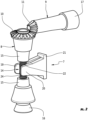
- Fig. 2
- shows a three-dimensional schematic view of the device for positioning the lighting body;
- Fig. 3
- shows a three-dimensional schematic view of a follower; and
- Fig. 4
- shows a partial section of the follower in a three-dimensional schematic view, in direction of an arrow IV.
- A lighting body of a vehicle shown schematically in
Fig. 1 comprises acase 1 with an articulatedlight module 2 arranged therein, such as a light source, a reflector of the lighting body, and similar. Saidmodule 2 is rotatable about thecentreline 3 thereof which, in the present embodiment, extends approximately horizontally and/or approximately perpendicularly to the direction A of the luminous flux. Furthermore, adevice 4 for positioning thelight module 2 with respect to ahorizontal centreline 5 of the lighting body and, respectively, with regard to the ideal direction A of the luminous flux is arranged on thecase 1. Saiddevice 4 for positioning thelight module 2 is fixed by means offixing means 6, wherein it cooperates simultaneously with afollower 7 associated with saidlight module 2. Saidfollower 7 can be formed either as an integral part of thelight module 2, or as a separate element which is attached to thelight module 2 in a manner known per se. Saiddevice 4 for positioning thelight module 2 is connected with saidfollower 7 by means of a force-locking joint and/or a form-locking joint. - Said
device 4 for positioning thelight module 2 is formed of at least twoactuators follower 7, wherein saidactuators actuator opposite actuator 9, 8 a transfer means 10, 11 mating with each other. Said transfer means 10, 11 are provided for transfer of motion from thefirst actuator 8 and, respectively, 9 to thesecond actuator 9 and, respectively, 8, the transfer means 10, 11 being selected in the present embodiment as a pair ofbevelled gears actuator stem actuators stem actuator fixing means 6. Thus, transfer of the rotational movement from thefirst actuator 8 and, respectively, 9 to thesecond actuator 9 and, respectively, 8 is achieved via the transfer means 10, 11. At least part of thestem actuators section 14 provided for mating and cooperating with saidfollower 7. The length of said threadedsection 14 exceeds the dimension of thefollower 7 in direction of the extension of thestem actuator section 14 there is attached a shiftingsection 15 the radial dimension thereof is larger then the radial dimension of the threadedsection 14. Further, the free end of eachactuator depression actuators actuator actuators - Said
follower 7 is either an integral part of thelight module 2, or is associated with the latter in a removable manner. At the side averted from thelight module 2 thefollower 7 is formed with a fork-like structure 18 comprising threadedplates plates actuators actuator 8, wherein they extend substantially beyond the centreline of the stem of theactuator 8. Said threadedplates base 21 of thefollower 7, which is further either separably or permanently associated with thelight module 2. Furthermore, each threadedplate chamfer 22, which facilitates placing theactuator 8 and, respectively, 9 between the threadedplates plates section 14 of theactuator 8 and, respectively, 9 with a threadedsection 22 comprising aninternal thread 23 provided for cooperation with anexternal thread 24 of the threadedsection 14. Saidthread - Said threaded
section 22 comprising theinternal thread 23 is formed on anarc 25, the centreline thereof approximately corresponds to thehorizontal centreline 5 of the lighting body and, respectively, thelight module 2, the latter is to be rotated about. Saidarc 25 lies in a vertical plane extending through the centreline of the threadedsection 14 and, respectively, theactuator 8, and in parallel with the fork-like structure 18 and, respectively, in parallel with the threadedplates section 22, which is provided in the fork-like structure 18, is formed in a manner to compensate movements over thecircular arc 25 and ensures, in each position of the fork-like structure 18 relative to theactuator 8, a constant contact in several threads between theouter thread 24 of the threadedsection 14 and theinner thread 23 of the fork-like structure 18 within the required positioning region of thelighting module 2. - Said
device 4 for positioning thelight module 2 provides for thelighting module 2 to be positioned in thecase 1 of thelighting body 2, thus protecting the elements of the lighting body against the overload in the terminal positioning region. Said protection is achieved in a manner, that said shiftingsection 15 which is associated with each end of the threadedsection 14 is pushed, in each extreme rotated position of the fork-like structure 18 and with continuous entering of torque into theactuator 8, between the threadedplates section 15 is greater than the radial dimension of the threadedsection 14 and, therefore, greater than the spacing between the threadedplates section 15 pushes the threadedplates outer thread 24 disengages theinternal thread 23 and simultaneously enables skipping of saidthreads actuator 8 can still rotate about its centreline, however, thefollower 7 can not be moved any more, and as a result thethreads
Claims (9)
- A device for positioning a lighting body of a vehicle, such as a headlamp or a fog lamp, comprising:a case (1) with an articulated light module (2) arranged therein, such as a light source or a reflector of the lighting body, said module (2) being rotatable about a centreline (3) thereof which extends approximately horizontally and/or approximately perpendicularly to the direction of the luminous flux, when the device for positioning a lighting body is mounted to the vehicle, anda device (4) for positioning the light module (2), wherein the device (4) for positioning the light module (2) with respect to a horizontal centreline (5) of the lighting body and, respectively, with regard to the ideal direction of the luminous flux is arranged on said case (1), said device (4) for positioning the light module (2) is formed of at least two actuators (8, 9) set at an angle with respect to each other and mutually cooperating, and a follower (7) associated with said light module (2),wherein said follower (7) is formed with a fork-like structure (18) comprising threaded plates (19, 20) that extend mutually in parallel and are spaced with regard to each other and are attached at the first end thereof to a base (21) of the follower (7), said threaded plates (19, 20) being formed in the region of cooperation with a threaded section (14) of the at least one (8) of the actuators (8, 9) with a threaded section (22), which comprises an internal thread (23) provided for cooperation with an outer thread (24) of the threaded section (14), characterised in that each said threaded section (22) comprising the internal thread (23) is formed on an arc (25) a centreline thereof approximately corresponds to the horizontal centreline (5) of the lighting body and, respectively, to the centreline (3) of the light module (2), the latter is to be rotated about and wherein said arc (25) lies in a vertical plane extending through the centreline of the threaded section (14) and in parallel with the threaded plates (19, 20), when the device for positioning a lighting body is mounted to the vehicle, wherein said threaded section (22) which is provided in the forklike structure (18) is configured to compensate movements over the circular arc (25) and ensures, in each position of the fork-like structure (18) relative to the actuator (8), a constant contact in several threads between the outer thread (24) of the threaded section (14) and the inner thread (23) of the fork-like structure (18) within the required positioning region of the light module (2).
- A device according to claim 1, characterized in that each actuator (8, 9) comprises at the place of the cooperation with the opposite actuator (9, 8) a transfer means (10, 11) mating with each other provided for a transfer of motion form the first actuator (8, 9) to the second actuator (9, 8).
- A device according to claim 2, characterized in that the transfer means (10, 11) are selected as a pair of bevelled gears (10, 11).
- A device according to claims 1 to 3, characterized in that each actuator (8, 9) comprises a stem (12, 13), at least part of the stem (12, 13) of at least one of the actuators (8, 9) being formed in the region of engagement and cooperation with said follower (7) with a threaded section (14), wherein a shifting section (15) being associated with each end of the threaded section (14), and at least one of the ends of each actuator (8, 9) is formed with a projection and/or a depression (16, 17) for engaging a tool to enter a torque into at least one of the actuators (8, 9).
- A device according to claim 4, characterized in that the radial dimension of the shifting section (15) is greater than the radial dimension of the threaded section (14).
- A device according to any of the preceding claims, characterized in that said device (4) for positioning the light module (2) is connected with said follower (7) by means of a force- locking joint and/or a form-locking joint.
- A device according to any of the preceding claims, characterized in that said follower (7) can be formed either as an integral part of the light module (2), or as a separate element attached to the light module (2) in a manner known per se.
- A lighting body for a vehicle, wherein the position of the lighting body can be set by a device according to any of the preceding claims.
- A motor vehicle provided with a lighting body for a vehicle wherein the position of the lighting body can be set by a device according to any of the preceding claims.
Applications Claiming Priority (2)
| Application Number | Priority Date | Filing Date | Title |
|---|---|---|---|
| SI201700158A SI25444A (en) | 2017-06-07 | 2017-06-07 | Set for position adjustment of light body |
| PCT/IB2018/053964 WO2018224938A1 (en) | 2017-06-07 | 2018-06-04 | A device for positioning a lighting body |
Publications (2)
| Publication Number | Publication Date |
|---|---|
| EP3634806A1 EP3634806A1 (en) | 2020-04-15 |
| EP3634806B1 true EP3634806B1 (en) | 2024-12-25 |
Family
ID=62948273
Family Applications (1)
| Application Number | Title | Priority Date | Filing Date |
|---|---|---|---|
| EP18742594.7A Active EP3634806B1 (en) | 2017-06-07 | 2018-06-04 | A device for positioning a lighting body |
Country Status (3)
| Country | Link |
|---|---|
| EP (1) | EP3634806B1 (en) |
| SI (1) | SI25444A (en) |
| WO (1) | WO2018224938A1 (en) |
Families Citing this family (3)
| Publication number | Priority date | Publication date | Assignee | Title |
|---|---|---|---|---|
| EP3983722A1 (en) | 2019-06-11 | 2022-04-20 | Signify Holding B.V. | Adjustable recessed lighting apparatus |
| FR3102827B1 (en) * | 2019-10-30 | 2022-11-04 | Psa Automobiles Sa | Trim correction device for a motor vehicle headlamp |
| EP3915835A1 (en) * | 2020-05-27 | 2021-12-01 | ZKW Group GmbH | Adjusting device |
Citations (2)
| Publication number | Priority date | Publication date | Assignee | Title |
|---|---|---|---|---|
| KR19980013184U (en) * | 1996-08-30 | 1998-06-05 | 양재신 | Aiming structure of car headlamp |
| DE102012111311A1 (en) * | 2012-11-23 | 2014-05-28 | Hella Kgaa Hueck & Co. | Recording arrangement of a light module in the housing of a headlamp |
Family Cites Families (8)
| Publication number | Priority date | Publication date | Assignee | Title |
|---|---|---|---|---|
| US5186532A (en) * | 1991-05-07 | 1993-02-16 | Textron Inc. | Headlamp adjusting mechanism and headlamp adjusting assembly |
| FR2722460B1 (en) * | 1994-07-13 | 1996-10-04 | Valeo Vision Sa | MOTOR VEHICLE PROJECTOR COMPRISING IMPROVED MEANS OF GUIDANCE INDICATION |
| FR2808316B1 (en) * | 2000-04-28 | 2002-07-12 | Valeo Vision | LIGHTING OR SIGNALING DEVICE FOR VEHICLE WITH REINFORCED PACKAGE |
| FR2902722B1 (en) * | 2006-06-23 | 2009-04-17 | Valeo Vision Sa | PROJECTOR HAVING A SWIVELDER REFLECTOR HAVING A NUT FOR ADJUSTING THE REFLECTOR ANGULAR POSITION |
| FR2951117B1 (en) * | 2009-10-12 | 2012-02-03 | Valeo Vision | DEVICE FOR ADJUSTING A DEVICE FOR LIGHTING AND / OR SIGNALING A MOTOR VEHICLE AND METHOD FOR MOUNTING SUCH A DEVICE |
| AT512215B1 (en) * | 2011-12-12 | 2013-09-15 | Zizala Lichtsysteme Gmbh | HEADLIGHTS, ESPECIALLY MOTORCYCLE HEADLIGHTS |
| CN103358979B (en) * | 2012-03-29 | 2015-11-18 | 本田技研工业株式会社 | The optical axis regulating mechanism of the head lamp of vehicle |
| FR2989333B1 (en) * | 2012-04-11 | 2018-01-12 | Valeo Vision Belgique | LIGHTING AND / OR SIGNALING DEVICE COMPRISING AN OPTIMIZED ADJUSTMENT MEANS |
-
2017
- 2017-06-07 SI SI201700158A patent/SI25444A/en not_active IP Right Cessation
-
2018
- 2018-06-04 EP EP18742594.7A patent/EP3634806B1/en active Active
- 2018-06-04 WO PCT/IB2018/053964 patent/WO2018224938A1/en not_active Ceased
Patent Citations (2)
| Publication number | Priority date | Publication date | Assignee | Title |
|---|---|---|---|---|
| KR19980013184U (en) * | 1996-08-30 | 1998-06-05 | 양재신 | Aiming structure of car headlamp |
| DE102012111311A1 (en) * | 2012-11-23 | 2014-05-28 | Hella Kgaa Hueck & Co. | Recording arrangement of a light module in the housing of a headlamp |
Also Published As
| Publication number | Publication date |
|---|---|
| EP3634806A1 (en) | 2020-04-15 |
| SI25444A (en) | 2018-12-31 |
| WO2018224938A1 (en) | 2018-12-13 |
Similar Documents
| Publication | Publication Date | Title |
|---|---|---|
| EP3634806B1 (en) | A device for positioning a lighting body | |
| EP2679444B1 (en) | Vehicle headlamp | |
| EP2744686B1 (en) | Headlight for a motor vehicle having an exchangeable complex light source | |
| CN103836571B (en) | Storing apparatus of the optical module in the shell of headlamp | |
| EP2436974A1 (en) | LED luminaire | |
| DE102007048911A1 (en) | Headlamp assembly with adjustable direction of the light beam | |
| CN107107810B (en) | Lighting corrector for a motor vehicle headlight with an improved stop | |
| KR102300342B1 (en) | Adjustment system for rotating at least one optically related component of a vehicle headlamp about a first and a second axis | |
| EP3540297A1 (en) | Vehicle headlamp | |
| US11458883B2 (en) | Adjustment device for a motor vehicle headlight | |
| CN110864263B (en) | Adjusting device for a motor vehicle headlight | |
| KR102668153B1 (en) | Lighting devices for automobile headlamps | |
| EP2652394B1 (en) | Headlamp for a vehicle having an led main light module | |
| FR2902722B1 (en) | PROJECTOR HAVING A SWIVELDER REFLECTOR HAVING A NUT FOR ADJUSTING THE REFLECTOR ANGULAR POSITION | |
| US7628516B2 (en) | Headlight adjusting assembly for groups of adjustable illuminating units | |
| CN113423605A (en) | Lighting device for a motor vehicle headlight | |
| KR101828371B1 (en) | Assembly device | |
| US10752160B2 (en) | Adjusting device | |
| EP3388738A1 (en) | Lighting apparatus and automotive vehicle | |
| CN103373272A (en) | Lighting and/or signalling device comprising an optimised adjusting mechanism | |
| US11654818B2 (en) | Adjustment device for a vehicle light emitting module | |
| DE19816364C2 (en) | Lamp housings, in particular headlight housings | |
| EP2115349B1 (en) | Headlight | |
| DE102005020304A1 (en) | Lamp for motor vehicle, has housing, where light beams are guided outward in main radiation direction, and reflector and light panel are adjustable relative to each other in main radiation direction | |
| US10697597B2 (en) | Housing, connector and system |
Legal Events
| Date | Code | Title | Description |
|---|---|---|---|
| STAA | Information on the status of an ep patent application or granted ep patent |
Free format text: STATUS: UNKNOWN |
|
| STAA | Information on the status of an ep patent application or granted ep patent |
Free format text: STATUS: THE INTERNATIONAL PUBLICATION HAS BEEN MADE |
|
| PUAI | Public reference made under article 153(3) epc to a published international application that has entered the european phase |
Free format text: ORIGINAL CODE: 0009012 |
|
| STAA | Information on the status of an ep patent application or granted ep patent |
Free format text: STATUS: REQUEST FOR EXAMINATION WAS MADE |
|
| 17P | Request for examination filed |
Effective date: 20191202 |
|
| AK | Designated contracting states |
Kind code of ref document: A1 Designated state(s): AL AT BE BG CH CY CZ DE DK EE ES FI FR GB GR HR HU IE IS IT LI LT LU LV MC MK MT NL NO PL PT RO RS SE SI SK SM TR |
|
| AX | Request for extension of the european patent |
Extension state: BA ME |
|
| DAV | Request for validation of the european patent (deleted) | ||
| DAX | Request for extension of the european patent (deleted) | ||
| STAA | Information on the status of an ep patent application or granted ep patent |
Free format text: STATUS: EXAMINATION IS IN PROGRESS |
|
| 17Q | First examination report despatched |
Effective date: 20220328 |
|
| GRAP | Despatch of communication of intention to grant a patent |
Free format text: ORIGINAL CODE: EPIDOSNIGR1 |
|
| STAA | Information on the status of an ep patent application or granted ep patent |
Free format text: STATUS: GRANT OF PATENT IS INTENDED |
|
| INTG | Intention to grant announced |
Effective date: 20240726 |
|
| GRAS | Grant fee paid |
Free format text: ORIGINAL CODE: EPIDOSNIGR3 |
|
| GRAA | (expected) grant |
Free format text: ORIGINAL CODE: 0009210 |
|
| STAA | Information on the status of an ep patent application or granted ep patent |
Free format text: STATUS: THE PATENT HAS BEEN GRANTED |
|
| AK | Designated contracting states |
Kind code of ref document: B1 Designated state(s): AL AT BE BG CH CY CZ DE DK EE ES FI FR GB GR HR HU IE IS IT LI LT LU LV MC MK MT NL NO PL PT RO RS SE SI SK SM TR |
|
| REG | Reference to a national code |
Ref country code: GB Ref legal event code: FG4D |
|
| REG | Reference to a national code |
Ref country code: CH Ref legal event code: EP |
|
| REG | Reference to a national code |
Ref country code: DE Ref legal event code: R096 Ref document number: 602018077916 Country of ref document: DE |
|
| REG | Reference to a national code |
Ref country code: IE Ref legal event code: FG4D |
|
| REG | Reference to a national code |
Ref country code: LT Ref legal event code: MG9D |
|
| PG25 | Lapsed in a contracting state [announced via postgrant information from national office to epo] |
Ref country code: HR Free format text: LAPSE BECAUSE OF FAILURE TO SUBMIT A TRANSLATION OF THE DESCRIPTION OR TO PAY THE FEE WITHIN THE PRESCRIBED TIME-LIMIT Effective date: 20241225 |
|
| PG25 | Lapsed in a contracting state [announced via postgrant information from national office to epo] |
Ref country code: FI Free format text: LAPSE BECAUSE OF FAILURE TO SUBMIT A TRANSLATION OF THE DESCRIPTION OR TO PAY THE FEE WITHIN THE PRESCRIBED TIME-LIMIT Effective date: 20241225 |
|
| PG25 | Lapsed in a contracting state [announced via postgrant information from national office to epo] |
Ref country code: BG Free format text: LAPSE BECAUSE OF FAILURE TO SUBMIT A TRANSLATION OF THE DESCRIPTION OR TO PAY THE FEE WITHIN THE PRESCRIBED TIME-LIMIT Effective date: 20241225 |
|
| PG25 | Lapsed in a contracting state [announced via postgrant information from national office to epo] |
Ref country code: NO Free format text: LAPSE BECAUSE OF FAILURE TO SUBMIT A TRANSLATION OF THE DESCRIPTION OR TO PAY THE FEE WITHIN THE PRESCRIBED TIME-LIMIT Effective date: 20250325 |
|
| PG25 | Lapsed in a contracting state [announced via postgrant information from national office to epo] |
Ref country code: LV Free format text: LAPSE BECAUSE OF FAILURE TO SUBMIT A TRANSLATION OF THE DESCRIPTION OR TO PAY THE FEE WITHIN THE PRESCRIBED TIME-LIMIT Effective date: 20241225 Ref country code: GR Free format text: LAPSE BECAUSE OF FAILURE TO SUBMIT A TRANSLATION OF THE DESCRIPTION OR TO PAY THE FEE WITHIN THE PRESCRIBED TIME-LIMIT Effective date: 20250326 |
|
| PG25 | Lapsed in a contracting state [announced via postgrant information from national office to epo] |
Ref country code: RS Free format text: LAPSE BECAUSE OF FAILURE TO SUBMIT A TRANSLATION OF THE DESCRIPTION OR TO PAY THE FEE WITHIN THE PRESCRIBED TIME-LIMIT Effective date: 20250325 |
|
| REG | Reference to a national code |
Ref country code: NL Ref legal event code: MP Effective date: 20241225 |
|
| PG25 | Lapsed in a contracting state [announced via postgrant information from national office to epo] |
Ref country code: NL Free format text: LAPSE BECAUSE OF FAILURE TO SUBMIT A TRANSLATION OF THE DESCRIPTION OR TO PAY THE FEE WITHIN THE PRESCRIBED TIME-LIMIT Effective date: 20241225 |
|
| REG | Reference to a national code |
Ref country code: AT Ref legal event code: MK05 Ref document number: 1753910 Country of ref document: AT Kind code of ref document: T Effective date: 20241225 |
|
| PG25 | Lapsed in a contracting state [announced via postgrant information from national office to epo] |
Ref country code: SM Free format text: LAPSE BECAUSE OF FAILURE TO SUBMIT A TRANSLATION OF THE DESCRIPTION OR TO PAY THE FEE WITHIN THE PRESCRIBED TIME-LIMIT Effective date: 20241225 |
|
| PG25 | Lapsed in a contracting state [announced via postgrant information from national office to epo] |
Ref country code: PL Free format text: LAPSE BECAUSE OF FAILURE TO SUBMIT A TRANSLATION OF THE DESCRIPTION OR TO PAY THE FEE WITHIN THE PRESCRIBED TIME-LIMIT Effective date: 20241225 |
|
| PGFP | Annual fee paid to national office [announced via postgrant information from national office to epo] |
Ref country code: DE Payment date: 20250423 Year of fee payment: 8 |
|
| PG25 | Lapsed in a contracting state [announced via postgrant information from national office to epo] |
Ref country code: ES Free format text: LAPSE BECAUSE OF FAILURE TO SUBMIT A TRANSLATION OF THE DESCRIPTION OR TO PAY THE FEE WITHIN THE PRESCRIBED TIME-LIMIT Effective date: 20241225 |
|
| PGFP | Annual fee paid to national office [announced via postgrant information from national office to epo] |
Ref country code: GB Payment date: 20250417 Year of fee payment: 8 |
|
| PG25 | Lapsed in a contracting state [announced via postgrant information from national office to epo] |
Ref country code: IS Free format text: LAPSE BECAUSE OF FAILURE TO SUBMIT A TRANSLATION OF THE DESCRIPTION OR TO PAY THE FEE WITHIN THE PRESCRIBED TIME-LIMIT Effective date: 20250425 |
|
| PG25 | Lapsed in a contracting state [announced via postgrant information from national office to epo] |
Ref country code: PT Free format text: LAPSE BECAUSE OF FAILURE TO SUBMIT A TRANSLATION OF THE DESCRIPTION OR TO PAY THE FEE WITHIN THE PRESCRIBED TIME-LIMIT Effective date: 20250428 |
|
| PG25 | Lapsed in a contracting state [announced via postgrant information from national office to epo] |
Ref country code: EE Free format text: LAPSE BECAUSE OF FAILURE TO SUBMIT A TRANSLATION OF THE DESCRIPTION OR TO PAY THE FEE WITHIN THE PRESCRIBED TIME-LIMIT Effective date: 20241225 |
|
| PGFP | Annual fee paid to national office [announced via postgrant information from national office to epo] |
Ref country code: FR Payment date: 20250422 Year of fee payment: 8 |
|
| PG25 | Lapsed in a contracting state [announced via postgrant information from national office to epo] |
Ref country code: AT Free format text: LAPSE BECAUSE OF FAILURE TO SUBMIT A TRANSLATION OF THE DESCRIPTION OR TO PAY THE FEE WITHIN THE PRESCRIBED TIME-LIMIT Effective date: 20241225 Ref country code: RO Free format text: LAPSE BECAUSE OF FAILURE TO SUBMIT A TRANSLATION OF THE DESCRIPTION OR TO PAY THE FEE WITHIN THE PRESCRIBED TIME-LIMIT Effective date: 20241225 |
|
| PG25 | Lapsed in a contracting state [announced via postgrant information from national office to epo] |
Ref country code: SK Free format text: LAPSE BECAUSE OF FAILURE TO SUBMIT A TRANSLATION OF THE DESCRIPTION OR TO PAY THE FEE WITHIN THE PRESCRIBED TIME-LIMIT Effective date: 20241225 |
|
| PG25 | Lapsed in a contracting state [announced via postgrant information from national office to epo] |
Ref country code: CZ Free format text: LAPSE BECAUSE OF FAILURE TO SUBMIT A TRANSLATION OF THE DESCRIPTION OR TO PAY THE FEE WITHIN THE PRESCRIBED TIME-LIMIT Effective date: 20241225 |
|
| PG25 | Lapsed in a contracting state [announced via postgrant information from national office to epo] |
Ref country code: IT Free format text: LAPSE BECAUSE OF FAILURE TO SUBMIT A TRANSLATION OF THE DESCRIPTION OR TO PAY THE FEE WITHIN THE PRESCRIBED TIME-LIMIT Effective date: 20241225 |
|
| PG25 | Lapsed in a contracting state [announced via postgrant information from national office to epo] |
Ref country code: SE Free format text: LAPSE BECAUSE OF FAILURE TO SUBMIT A TRANSLATION OF THE DESCRIPTION OR TO PAY THE FEE WITHIN THE PRESCRIBED TIME-LIMIT Effective date: 20241225 |
|
| REG | Reference to a national code |
Ref country code: DE Ref legal event code: R097 Ref document number: 602018077916 Country of ref document: DE |
|
| PG25 | Lapsed in a contracting state [announced via postgrant information from national office to epo] |
Ref country code: DK Free format text: LAPSE BECAUSE OF FAILURE TO SUBMIT A TRANSLATION OF THE DESCRIPTION OR TO PAY THE FEE WITHIN THE PRESCRIBED TIME-LIMIT Effective date: 20241225 |
|
| PLBE | No opposition filed within time limit |
Free format text: ORIGINAL CODE: 0009261 |
|
| STAA | Information on the status of an ep patent application or granted ep patent |
Free format text: STATUS: NO OPPOSITION FILED WITHIN TIME LIMIT |
|
| REG | Reference to a national code |
Ref country code: CH Ref legal event code: L10 Free format text: ST27 STATUS EVENT CODE: U-0-0-L10-L00 (AS PROVIDED BY THE NATIONAL OFFICE) Effective date: 20251105 |
|
| 26N | No opposition filed |
Effective date: 20250926 |
|
| REG | Reference to a national code |
Ref country code: CH Ref legal event code: H13 Free format text: ST27 STATUS EVENT CODE: U-0-0-H10-H13 (AS PROVIDED BY THE NATIONAL OFFICE) Effective date: 20260127 |
|
| PG25 | Lapsed in a contracting state [announced via postgrant information from national office to epo] |
Ref country code: MC Free format text: LAPSE BECAUSE OF FAILURE TO SUBMIT A TRANSLATION OF THE DESCRIPTION OR TO PAY THE FEE WITHIN THE PRESCRIBED TIME-LIMIT Effective date: 20241225 |
|
| PG25 | Lapsed in a contracting state [announced via postgrant information from national office to epo] |
Ref country code: LU Free format text: LAPSE BECAUSE OF NON-PAYMENT OF DUE FEES Effective date: 20250604 |
|
| REG | Reference to a national code |
Ref country code: BE Ref legal event code: MM Effective date: 20250630 |
|
| PG25 | Lapsed in a contracting state [announced via postgrant information from national office to epo] |
Ref country code: IE Free format text: LAPSE BECAUSE OF NON-PAYMENT OF DUE FEES Effective date: 20250604 |
|
| PG25 | Lapsed in a contracting state [announced via postgrant information from national office to epo] |
Ref country code: BE Free format text: LAPSE BECAUSE OF NON-PAYMENT OF DUE FEES Effective date: 20250630 |
|
| PG25 | Lapsed in a contracting state [announced via postgrant information from national office to epo] |
Ref country code: CH Free format text: LAPSE BECAUSE OF NON-PAYMENT OF DUE FEES Effective date: 20250630 |