EP3634795B1 - A shade assembly used in vehicles - Google Patents
A shade assembly used in vehicles Download PDFInfo
- Publication number
- EP3634795B1 EP3634795B1 EP18801078.9A EP18801078A EP3634795B1 EP 3634795 B1 EP3634795 B1 EP 3634795B1 EP 18801078 A EP18801078 A EP 18801078A EP 3634795 B1 EP3634795 B1 EP 3634795B1
- Authority
- EP
- European Patent Office
- Prior art keywords
- tube
- cap
- mounting member
- assembly
- rod
- Prior art date
- Legal status (The legal status is an assumption and is not a legal conclusion. Google has not performed a legal analysis and makes no representation as to the accuracy of the status listed.)
- Active
Links
Images






Classifications
-
- B—PERFORMING OPERATIONS; TRANSPORTING
- B60—VEHICLES IN GENERAL
- B60J—WINDOWS, WINDSCREENS, NON-FIXED ROOFS, DOORS, OR SIMILAR DEVICES FOR VEHICLES; REMOVABLE EXTERNAL PROTECTIVE COVERINGS SPECIALLY ADAPTED FOR VEHICLES
- B60J1/00—Windows; Windscreens; Accessories therefor
- B60J1/20—Accessories, e.g. wind deflectors, blinds
- B60J1/2011—Blinds; curtains or screens reducing heat or light intensity
- B60J1/2013—Roller blinds
- B60J1/2036—Roller blinds characterised by structural elements
- B60J1/2058—Springs for compensating the number of windings of the blind on the tube in case winding tube and draw bar are driven together
-
- B—PERFORMING OPERATIONS; TRANSPORTING
- B60—VEHICLES IN GENERAL
- B60J—WINDOWS, WINDSCREENS, NON-FIXED ROOFS, DOORS, OR SIMILAR DEVICES FOR VEHICLES; REMOVABLE EXTERNAL PROTECTIVE COVERINGS SPECIALLY ADAPTED FOR VEHICLES
- B60J1/00—Windows; Windscreens; Accessories therefor
- B60J1/20—Accessories, e.g. wind deflectors, blinds
- B60J1/2011—Blinds; curtains or screens reducing heat or light intensity
- B60J1/2013—Roller blinds
- B60J1/2033—Roller blinds characterised by the spring motor
-
- B—PERFORMING OPERATIONS; TRANSPORTING
- B60—VEHICLES IN GENERAL
- B60J—WINDOWS, WINDSCREENS, NON-FIXED ROOFS, DOORS, OR SIMILAR DEVICES FOR VEHICLES; REMOVABLE EXTERNAL PROTECTIVE COVERINGS SPECIALLY ADAPTED FOR VEHICLES
- B60J1/00—Windows; Windscreens; Accessories therefor
- B60J1/20—Accessories, e.g. wind deflectors, blinds
- B60J1/2011—Blinds; curtains or screens reducing heat or light intensity
- B60J1/2013—Roller blinds
- B60J1/2036—Roller blinds characterised by structural elements
- B60J1/205—Winding tubes, e.g. telescopic tubes or conically shaped tubes
-
- B—PERFORMING OPERATIONS; TRANSPORTING
- B60—VEHICLES IN GENERAL
- B60J—WINDOWS, WINDSCREENS, NON-FIXED ROOFS, DOORS, OR SIMILAR DEVICES FOR VEHICLES; REMOVABLE EXTERNAL PROTECTIVE COVERINGS SPECIALLY ADAPTED FOR VEHICLES
- B60J1/00—Windows; Windscreens; Accessories therefor
- B60J1/20—Accessories, e.g. wind deflectors, blinds
- B60J1/2011—Blinds; curtains or screens reducing heat or light intensity
- B60J1/2013—Roller blinds
- B60J1/2036—Roller blinds characterised by structural elements
- B60J1/2052—Guides
-
- B—PERFORMING OPERATIONS; TRANSPORTING
- B60—VEHICLES IN GENERAL
- B60J—WINDOWS, WINDSCREENS, NON-FIXED ROOFS, DOORS, OR SIMILAR DEVICES FOR VEHICLES; REMOVABLE EXTERNAL PROTECTIVE COVERINGS SPECIALLY ADAPTED FOR VEHICLES
- B60J1/00—Windows; Windscreens; Accessories therefor
- B60J1/20—Accessories, e.g. wind deflectors, blinds
- B60J1/2011—Blinds; curtains or screens reducing heat or light intensity
- B60J1/2013—Roller blinds
- B60J1/2063—Mounting arrangements for roller blind or its storage box, e.g. integration into beltline or window frame
Definitions
- the invention relates to a shade assembly which is used in vehicles and allows the shade to be retracted when it is released.
- shade assemblies are known, which are used in vehicles and allow the shade to be retracted.
- the number of parts in the mechanisms for retracting the shade is rather high, and hence its assembly is difficult and the cost of manufacture is high. Further, the costs are much higher in these mechanisms, in the case that the rotational movement required for retracting the shade is provided by drive members. Therefore, there is a need for solutions which have lesser parts, is easy to assembly and have reduced cost of manufacture such that the shade is enabled to retract in the vehicles.
- Patent Application US 2016/0083998 discloses a roller shade assembly a cylindrical tube having an inner surface defining an axial bore; a spindle including an outer threaded portion defining a helical groove, the spindle being configured to be received in the axial bore of the cylindrical tube for axial movement in the cylindrical tube at one end of the cylindrical tube; and at least one tracking element operatively associated with the cylindrical tube, the at least one tracking element being configured for riding in the helical groove to convert axial rotation of cylindrical tube into axial movement of the cylindrical tube on the support tube.
- the tracking element engages the helical groove from a position proximal to one end of the cylindrical tube.
- the starting axial position of the cylindrical tube in relation to the support tube is configured to be adjustable by manually rotating the spindle without rotating the support tube.
- the object of the invention is to provide a shade assembly which allows the shade to be retracted, has less number of parts and is easy to assembly.
- FIG 1 is an exploded view of a first assembly (1).
- the first assembly (1) generally has a tube (7) for winding a shade used in vehicles, a rod (9) disposed linearly within the tube (7), a first mounting member (12) through which said rod (9) is passed, a first spring (8) wound onto the rod (9), and opposing caps (4, 5) at which the ends of the tube (7) are located.
- a first cap (4) shown in the Figure 2 and Figure 3 has a geometrically cylindrical shape.
- a first cap recess (41) is present on the first cap (4).
- Said first cap recess (41) has a second cap groove (52).
- said first cap recess (41) and the second cap groove (52) is provided in the form of a circle.
- the first cap (4) has at least one cap flange (43) thereon, which is configured to be away from the cap. At least one connecting hole (44) is present on the first cap flange (43).
- Figure 4 and Figure 5 is representative and sectional views of a guiding member (10) in the first and second shade assembly.
- the guiding member (10) is generally cylindrical.
- the guiding member (10) is formed by a first body (101) and a second body (102), which have cylindrical shapes.
- the guiding member (10) is formed by end-to-end joining the first body (101) and the second body (102), which have different diameters.
- a guiding member channel (104) is present on the front surface (103) of the first body (101) in the guiding member (10).
- said guiding member channel (104) has a "C" shape.
- the first body (101) of the guiding member (104) has a guiding member hole (105).
- Figure 6, Figure 7 and Figure 8 shows a head (11) comprised in the first assembly (1). Said head (11) has a generally conical surface (102). A groove (111) is located at the middle of the head (11).
- Figure 9 and Figure 10 show a first spring (8) in the first assembly (1).
- the first spring (8) has a first helical portion (81) of a circular shape and a first hook portion (82) at both ends of the first helical portion (81).
- Figure 11 and Figure 12 are views of a first mounting member (12) in the first assembly (1).
- the first mounting member (12) comprises a first cylindrical mounting member body (121), a first mounting member recess (124) provided within said first mounting member body (121), and a spindle (122) extending horizontally away from the first mounting member (12) through the first mounting member recess (124).
- a first mounting member channel (126) extends through said spindle (122).
- a first grooved portion (123) is provided at one end of the spindle (122).
- a tab (125) is provided on an inner wall of the first mounting member body (121) facing the first mounting member recess (124). Said tab (125) is defined as an extension extending from the inner wall of the first mounting member body (121) to the spindle (122).
- Figure 13 and Figure 14 are views of a second cap (5) in the first assembly (1).
- the second cap (5) is cylindrical in shape.
- a second cap recess (51) is provided on the second cap (5).
- said second cap recess (51) is circular in shape.
- Said second cap recess (51) has a second cap groove (52).
- At least one second cap flange (53) configured to be away from the cap is provided on the second cap (5).
- At least one second connecting hole (54) is provided on the second cap flange (53).
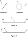
- Figure 34 and Figure 35 are views of a circular linear rod (9) in the first assembly (1).
- a first protrusion (91) is provided proximal to one end of the rod (9).
- a second protrusion (92) is provided at the other end of the rod (9).
- Said second protrusion (92) is conical in shape.
- FIG 15 and Figure 16 are exploded and sectional views of a second assembly (3).
- the second assembly (3) comprises generally a tube (7) for winding a shade used in vehicles, a second spring (13) disposed linearly within the tube (7), a third cap (17) having an extension located at the opposing ends of the tube (7) and extending through the tube (7) and a spring fixing member (16) located fixedly within the tube (7) for fastening the second spring (13).
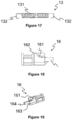
- the second spring (13) in the second assembly (3) shown in Figure 17 has a second circular helical portion (131) and at least one second hook portion (132) at both ends of the second helical portion (131).
- said second hook portion (132) has a "C" shape.
- FIG 18 and figure 19 are views of the spring fixing member (16).
- the spring fixing member (16) has a rectangular shape and has a first slot (161) thereon. In a preferred embodiment, said first slot (161) is inclined downwardly from an upper surface (162) of the spring fixing member (16).
- a second spindle (164) extending horizontally from a side surface (163) of the spring fixing member (16).
- Figure 20 and Figure 21 are views of a tube guiding member (15) in the second assembly (3).
- Said tube guiding member (15) has a circular shape.
- the tube guiding member (15) has a tube guiding member channel (151) therethrough and a second grooved portion (152) on a lateral surface (153) thereof. Also, said lateral surface (153) has a protrusion (154).
- the tube guiding member (15) has a tube guiding member extension (155) on one end thereof, and a first circular ridge (156) and a second circular ridge (157) on the other end thereof, in an opposite direction.
- Figure 22 and Figure 23 are views of a third cap (17) in the second assembly (3).
- the third cap (17) has generally a cylindrical shape. There is provided a third cap recess (171) on the third cap (17).
- said third cap recess (171) is circular in shape. At least one third cap flange (172) configured to be away from the cap is provided on the third cap (17). At least one third connecting hole (173) is provided on the third cap flange (172). There is provided a third cap extension (174) configured to be away from the third cap recess (171) and a circular wall (176) in said third cap recess (171). In a preferred embodiment, said wall is provided in a "C" shape. Further, a second slot (175) is provided on the third cap extension (174).
- Figure 32 shows views of the cylindrical tube (7) used in the first assembly (1) and second assembly (3).
- Said cylindrical tube (7) has a longitudinal aperture (71) thereon.
- the tube (7) is in the form of "C" shape.
- the first spring (8) is wound onto the rod (9), and the first spring (8) is attached to the second protrusion (92) of the rod (9) from one side thereof and is fixed to the head (11).
- the first spring (8) is attached to the first grooved portion (123) from the other side thereof.
- the first protrusion (91) of the rod (9) is passed through the first mounting member channel (126).
- the rod (9) is disposed within the tube (7) along with the first spring (8) thereon.
- the rod (9) is placed in the second cap groove (52) of the second cap (5) from one side thereof such that it will not rotate and is positioned in the guiding member (10) from the other side thereof.
- the guiding member (10) is positioned in the first cap groove (42) of the first cap (4).
- One end of the tube (7) is located within the guiding member channel (104).
- the system thus mounted is placed in the housing channel (61) and fixed by at least one connecting member (19) through the connecting holes (44, 54) on the first cap (4) and second cap (5), and the housing hole (62).
- energy is accumulated in the first spring (8) by the rotational movement of the tube (7).
- the energy accumulated in the first spring (8) is used to retract the shade by rotating the tube (7) in the opposite direction.
- the second spring is positioned between the spring fixing member (16) and the third cap (17) on the tube.
- the second spring (13) is fixed by being attached to the first slot (161) on the spring fixing member (16) from one end thereof and to the second slot (175) on the third cap (17) from the other end thereof.
- the tube guiding member (15) is provided at both ends of the tube (7) and the third cap extension (174) of the third cap (17) is passed through the tube guiding member channel (151).
- the protrusion (154) is located at the aperture of the tube.
- the tube (7) is located at the second slot (171) by the circular wall (176) from both ends thereof.
- the system thus mounted is placed in the housing channel (61) and fixed by at least one connecting member (19) through the third cap connecting holes (173) on the third caps (13), and the housing hole (62).
- energy is accumulated in the second spring (13) by the rotational movement of the tube (7).
- the energy accumulated in the second spring (13) is used to retract the shade by rotating the tube (7) in the opposite direction.
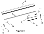
- a further embodiment of the invention comprises generally a tube (7) for winding a shade, a rod (9) disposed linearly within the tube (7), a first mounting member (12) through which said rod (9) is passed, a first spring (8) wound onto the rod (9), and opposing first cap (4) and fourth cap (18) at which the ends of the tube (7) are located.
- Figure 24 is an exploded view of mentioned further embodiment of the invention and Figure 25 is an sectional view of said further embodiment.
- Figure 26 and Figure 27 are views of the fourth cap (18).
- the fourth cap (18) is cylindrical in shape.
- a fourth cap recess (181) is provided on the fourth cap (18).
- said fourth cap recess (181) is circular in shape.
- a circular ridge (183) is provided in said fourth cap recess (181).
- FIG. 28 and Figure 30 are views of the second mounting member (14) in the further embodiment of the invention.
- the second mounting member (14) comprises a second cylindrical mounting member body (141) and a threaded portion (147) with at least one thread provided on a first surface (142) of said second mounting member body (141).
- the first spring (8) is wound onto the rod (9), and the first spring (8) is attached to the second protrusion (92) of the rod (9) from one side thereof and is fixed to the head (11).
- the rod (9) is inserted into the hole (146) from the other side thereof, whereas one end of the tube (7) is positioned in the second mounting member channel (145).
- the extension (144) is passed through the fourth cap channel (182). In such case, threads of the corresponding threaded portion (184) and the threaded portion (147) are complementarily integrated.
- the rod (9) is disposed within the tube (7) along with the first spring (8) thereon.
Landscapes
- Engineering & Computer Science (AREA)
- Mechanical Engineering (AREA)
- Non-Portable Lighting Devices Or Systems Thereof (AREA)
- Operating, Guiding And Securing Of Roll- Type Closing Members (AREA)
- Curtains And Furnishings For Windows Or Doors (AREA)
- Blinds (AREA)
Description
- The invention relates to a shade assembly which is used in vehicles and allows the shade to be retracted when it is released.
- In the state of the art, shade assemblies are known, which are used in vehicles and allow the shade to be retracted. In such shade assemblies, the number of parts in the mechanisms for retracting the shade is rather high, and hence its assembly is difficult and the cost of manufacture is high. Further, the costs are much higher in these mechanisms, in the case that the rotational movement required for retracting the shade is provided by drive members. Therefore, there is a need for solutions which have lesser parts, is easy to assembly and have reduced cost of manufacture such that the shade is enabled to retract in the vehicles.
- Patent Application
US 2016/0083998 discloses a roller shade assembly a cylindrical tube having an inner surface defining an axial bore; a spindle including an outer threaded portion defining a helical groove, the spindle being configured to be received in the axial bore of the cylindrical tube for axial movement in the cylindrical tube at one end of the cylindrical tube; and at least one tracking element operatively associated with the cylindrical tube, the at least one tracking element being configured for riding in the helical groove to convert axial rotation of cylindrical tube into axial movement of the cylindrical tube on the support tube. The tracking element engages the helical groove from a position proximal to one end of the cylindrical tube. The starting axial position of the cylindrical tube in relation to the support tube is configured to be adjustable by manually rotating the spindle without rotating the support tube. - Patent Application
US5226467A discloses a wind-shield blind system to thermally insulate the windshield of a car. The system includes a spindle tube with a spindle tube mechanism which allows the blind to extend only, preventing the blind from being accidentally rewound by locking the spindle tube in a stationary position at any of a plurality of positions in its range of extension. The spindle tube mechanism includes a push block which, when activated, causes the blind to be automatically rewound. - Patent Application
JP2014226969A - The object of the invention is to provide a shade assembly which allows the shade to be retracted, has less number of parts and is easy to assembly.
- Another object of the invention is to provide a shade assembly having a reduced cost of manufacture.
- The invention is set out in the appended set of claims.
- The following second assembly and further embodiment are not according to the invention and are present for illustration purposes only.
-
Figure 1 is an exploded view showing the first assembly. -
Figure 2 is a representative view of a first cap in the first assembly. -
Figure 3 is a sectional view of a first cap in the first assembly. -
Figure 4 is a representative view of a guiding member in the first assembly. -
Figure 5 is a sectional view of a guiding member in the first assembly. -
Figure 6 is a representative view of a head in the first assembly. -
Figure 7 is a top view of a head in the first assembly. -
Figure 8 is a sectional view of a head in the first assembly. -
Figure 9 is a top view of a spring in the first assembly. -
Figure 10 is a front view of a spring in the first assembly. -
Figure 11 is a representative view of a mounting member in the first assembly. -
Figure 12 is a sectional view of a mounting member in the first assembly. -
Figure 13 is a representative view of a second cap in the first assembly. -
Figure 14 is a sectional view of a second cap in the first assembly. -
Figure 15 is an exploded view showing the second assembly. -
Figure 16 is a sectional view showing the second assembly. -
Figure 17 is a front view of a second spring in the second assembly. -
Figure 18 is a front view of a spring fixing member in the second assembly. -
Figure 19 is a representative view of a spring fixing member in the second assembly. -
Figure 20 is a representative view of a tube guiding member in the second assembly. -
Figure 21 is a sectional view of a tube guiding member in the second assembly. -
Figure 22 is a representative view of a third cap in the second assembly. -
Figure 23 is a sectional view of a third cap in the second assembly. -
Figure 24 is an exploded view showing a further embodiment of the invention. -
Figure 25 is a sectional view showing mentioned further embodiment. -
Figure 26 is a representative view of a fourth cap in said further embodiment. -
Figure 27 is a sectional view of a fourth cap in the further embodiment. -
Figure 28 is a representative view of a second mounting member in the further embodiment. -
Figure 29 is another representative view of a second mounting member in the further embodiment. -
Figure 30 is a sectional view of a second mounting member in the further embodiment. -
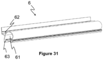
Figure 31 is a representative view of a housing in the first and second assembly. -
Figure 32 is a representative view of a tube in the first and second assembly. -
Figure 33 is a front view of a tube in the first and second assembly. -
Figure 34 is a front view showing a rod in the first assembly. -
Figure 35 is a sectional view showing a rod in the first assembly. - In this detailed description, three different shade assemblies used in vehicles are described by way of examples only for better understanding the subject matter without limitation.
-
Figure 1 is an exploded view of a first assembly (1). The first assembly (1) generally has a tube (7) for winding a shade used in vehicles, a rod (9) disposed linearly within the tube (7), a first mounting member (12) through which said rod (9) is passed, a first spring (8) wound onto the rod (9), and opposing caps (4, 5) at which the ends of the tube (7) are located. A first cap (4) shown in theFigure 2 and Figure 3 has a geometrically cylindrical shape. A first cap recess (41) is present on the first cap (4). Said first cap recess (41) has a second cap groove (52). In a preferred embodiment, said first cap recess (41) and the second cap groove (52) is provided in the form of a circle. The first cap (4) has at least one cap flange (43) thereon, which is configured to be away from the cap. At least one connecting hole (44) is present on the first cap flange (43).Figure 4 and Figure 5 is representative and sectional views of a guiding member (10) in the first and second shade assembly. The guiding member (10) is generally cylindrical. The guiding member (10) is formed by a first body (101) and a second body (102), which have cylindrical shapes. In a more detailed embodiment, the guiding member (10) is formed by end-to-end joining the first body (101) and the second body (102), which have different diameters. A guiding member channel (104) is present on the front surface (103) of the first body (101) in the guiding member (10). In a preferred embodiment, said guiding member channel (104) has a "C" shape. Also, the first body (101) of the guiding member (104) has a guiding member hole (105).Figure 6, Figure 7 and Figure 8 shows a head (11) comprised in the first assembly (1). Said head (11) has a generally conical surface (102). A groove (111) is located at the middle of the head (11).Figure 9 and Figure 10 show a first spring (8) in the first assembly (1). The first spring (8) has a first helical portion (81) of a circular shape and a first hook portion (82) at both ends of the first helical portion (81).Figure 11 and Figure 12 are views of a first mounting member (12) in the first assembly (1). The first mounting member (12) comprises a first cylindrical mounting member body (121), a first mounting member recess (124) provided within said first mounting member body (121), and a spindle (122) extending horizontally away from the first mounting member (12) through the first mounting member recess (124). A first mounting member channel (126) extends through said spindle (122). A first grooved portion (123) is provided at one end of the spindle (122). A tab (125) is provided on an inner wall of the first mounting member body (121) facing the first mounting member recess (124). Said tab (125) is defined as an extension extending from the inner wall of the first mounting member body (121) to the spindle (122).Figure 13 and Figure 14 are views of a second cap (5) in the first assembly (1). The second cap (5) is cylindrical in shape. A second cap recess (51) is provided on the second cap (5). In a preferred embodiment, said second cap recess (51) is circular in shape. Said second cap recess (51) has a second cap groove (52). At least one second cap flange (53) configured to be away from the cap is provided on the second cap (5). At least one second connecting hole (54) is provided on the second cap flange (53).Figure 34 and Figure 35 are views of a circular linear rod (9) in the first assembly (1). A first protrusion (91) is provided proximal to one end of the rod (9). A second protrusion (92) is provided at the other end of the rod (9). Said second protrusion (92) is conical in shape. -
Figure 15 andFigure 16 are exploded and sectional views of a second assembly (3). The second assembly (3) comprises generally a tube (7) for winding a shade used in vehicles, a second spring (13) disposed linearly within the tube (7), a third cap (17) having an extension located at the opposing ends of the tube (7) and extending through the tube (7) and a spring fixing member (16) located fixedly within the tube (7) for fastening the second spring (13). The second spring (13) in the second assembly (3) shown inFigure 17 has a second circular helical portion (131) and at least one second hook portion (132) at both ends of the second helical portion (131). In a preferred embodiment, said second hook portion (132) has a "C" shape.Figure 18 and figure 19 are views of the spring fixing member (16). The spring fixing member (16) has a rectangular shape and has a first slot (161) thereon. In a preferred embodiment, said first slot (161) is inclined downwardly from an upper surface (162) of the spring fixing member (16). There is provided a second spindle (164) extending horizontally from a side surface (163) of the spring fixing member (16).Figure 20 and Figure 21 are views of a tube guiding member (15) in the second assembly (3). Said tube guiding member (15) has a circular shape. The tube guiding member (15) has a tube guiding member channel (151) therethrough and a second grooved portion (152) on a lateral surface (153) thereof. Also, said lateral surface (153) has a protrusion (154). The tube guiding member (15) has a tube guiding member extension (155) on one end thereof, and a first circular ridge (156) and a second circular ridge (157) on the other end thereof, in an opposite direction.Figure 22 and Figure 23 are views of a third cap (17) in the second assembly (3). The third cap (17) has generally a cylindrical shape. There is provided a third cap recess (171) on the third cap (17). - In a preferred embodiment, said third cap recess (171) is circular in shape. At least one third cap flange (172) configured to be away from the cap is provided on the third cap (17). At least one third connecting hole (173) is provided on the third cap flange (172). There is provided a third cap extension (174) configured to be away from the third cap recess (171) and a circular wall (176) in said third cap recess (171). In a preferred embodiment, said wall is provided in a "C" shape. Further, a second slot (175) is provided on the third cap extension (174).
-
Figure 31 shows a housing (6) used in the first assembly (1) and second assembly (3). Said housing (6) has a housing channel (61) thereon in which the tube (7) is accommodated. In a preferred embodiment, said housing channel (61) is a hollow cylinder. Said housing channel (61) has a housing aperture (63) which communicates with outside and allows the shade to pass through. -
Figure 32 shows views of the cylindrical tube (7) used in the first assembly (1) and second assembly (3). Said cylindrical tube (7) has a longitudinal aperture (71) thereon. In a more detailed embodiment, the tube (7) is in the form of "C" shape. - Assembly and operation of the first assembly (1) is as follows: The first spring (8) is wound onto the rod (9), and the first spring (8) is attached to the second protrusion (92) of the rod (9) from one side thereof and is fixed to the head (11). The first spring (8) is attached to the first grooved portion (123) from the other side thereof. The first protrusion (91) of the rod (9) is passed through the first mounting member channel (126). The rod (9) is disposed within the tube (7) along with the first spring (8) thereon. The rod (9) is placed in the second cap groove (52) of the second cap (5) from one side thereof such that it will not rotate and is positioned in the guiding member (10) from the other side thereof. The guiding member (10) is positioned in the first cap groove (42) of the first cap (4). One end of the tube (7) is located within the guiding member channel (104). The system thus mounted is placed in the housing channel (61) and fixed by at least one connecting member (19) through the connecting holes (44, 54) on the first cap (4) and second cap (5), and the housing hole (62). In the first assembly (1) thus mounted, energy is accumulated in the first spring (8) by the rotational movement of the tube (7). The energy accumulated in the first spring (8) is used to retract the shade by rotating the tube (7) in the opposite direction.
- Assembly and operation of the second assembly (3) is as follows: The second spring is positioned between the spring fixing member (16) and the third cap (17) on the tube. The second spring (13) is fixed by being attached to the first slot (161) on the spring fixing member (16) from one end thereof and to the second slot (175) on the third cap (17) from the other end thereof. The tube guiding member (15) is provided at both ends of the tube (7) and the third cap extension (174) of the third cap (17) is passed through the tube guiding member channel (151). The protrusion (154) is located at the aperture of the tube. The tube (7) is located at the second slot (171) by the circular wall (176) from both ends thereof. The system thus mounted is placed in the housing channel (61) and fixed by at least one connecting member (19) through the third cap connecting holes (173) on the third caps (13), and the housing hole (62). In the first assembly (1) thus mounted, energy is accumulated in the second spring (13) by the rotational movement of the tube (7). The energy accumulated in the second spring (13) is used to retract the shade by rotating the tube (7) in the opposite direction.
- A further embodiment of the invention comprises generally a tube (7) for winding a shade, a rod (9) disposed linearly within the tube (7), a first mounting member (12) through which said rod (9) is passed, a first spring (8) wound onto the rod (9), and opposing first cap (4) and fourth cap (18) at which the ends of the tube (7) are located.
Figure 24 is an exploded view of mentioned further embodiment of the invention andFigure 25 is an sectional view of said further embodiment.Figure 26 and Figure 27 are views of the fourth cap (18). The fourth cap (18) is cylindrical in shape. A fourth cap recess (181) is provided on the fourth cap (18). In a preferred embodiment, said fourth cap recess (181) is circular in shape. A circular ridge (183) is provided in said fourth cap recess (181). There is provided a fourth cap channel (182) extending along the fourth cap (18) from the ridge (183). In addition, a corresponding threaded portion (184) is provided on said ridge (183) on which a corresponding thread is present. At least one fourth cap flange (185) configured to be away from the cap is provided on the fourth cap (18). At least one fourth connecting hole (186) is provided on the fourth cap flange (185).Figure 28, Figure 29 and Figure 30 are views of the second mounting member (14) in the further embodiment of the invention. The second mounting member (14) comprises a second cylindrical mounting member body (141) and a threaded portion (147) with at least one thread provided on a first surface (142) of said second mounting member body (141). Said threaded portion (147) is configured to correspond to the threaded portion (184) on the fourth cap (18). In a more detailed embodiment, the threaded portion (147) and the corresponding threaded portion (184) are complementary to each other. On the other hand, there is provided an extension (144) extending horizontally away from the second mounting member (14) on the first surface (142). There is provided a second mounting member channel (145) on a second surface (143) corresponding to the first surface (142). In a preferred embodiment, said second mounting member channel (145) has a "C" shape. There is provided a hole (146) which is located on the second surface (143) of the second mounting member (14) and is extended along at least part of the second mounting member body (141). - Assembly and operation of the further embodiment of the invention is as follows: The first spring (8) is wound onto the rod (9), and the first spring (8) is attached to the second protrusion (92) of the rod (9) from one side thereof and is fixed to the head (11). The rod (9) is inserted into the hole (146) from the other side thereof, whereas one end of the tube (7) is positioned in the second mounting member channel (145). The extension (144) is passed through the fourth cap channel (182). In such case, threads of the corresponding threaded portion (184) and the threaded portion (147) are complementarily integrated. The rod (9) is disposed within the tube (7) along with the first spring (8) thereon. The rod (9) is passed through the fourth cap (18) from one side thereof such that it will not rotate and is positioned in the guiding member (10) from the other side thereof. The guiding member (10) is positioned in the first cap groove (42) of the first cap (4). The system thus mounted is placed in the housing channel (61) and fixed by at least one connecting member (19) through the connecting holes (44, 54) on the first cap (4) and fourth cap (18), and the housing hole (62). The corresponding threaded portion (184) and the threaded portion (147) are disengaged by a force applied linearly to the extension (144). In the first assembly (1) thus mounted, energy is accumulated in the first spring (8) by the rotational movement of the tube (7). The energy accumulated in the first spring (8) is used to retract the shade by rotating the tube (7) in the opposite direction.
-
- 1. First assembly
- 3. Second assembly
- 4. First cap
- 41. First cap recess
- 42. First cap groove
- 43. First cap flange
- 44. First connecting hole
- 5. Second cap
- 51. Second cap recess
- 52. Second cap groove
- 53. Second cap flange
- 54. Second connecting hole
- 6. Housing
- 61. Housing channel
- 62. Housing hole
- 63. Housing aperture
- 7. Tube
- 71. Aperture
- 8. First spring
- 81. First helical portion
- 82. First hook portion
- 9. Rod
- 91. First protrusion
- 92. Second protrusion
- 10. Guiding member
- 101. First body
- 102. Second body
- 103. Front surface
- 104. Guiding member channel
- 105. Guiding member hole
- 11. Head
- 111. Groove
- 112. Conical surface
- 12. First mounting member
- 121. First mounting member body
- 122. Spindle
- 123. First grooved portion
- 124. First mounting member recess
- 125. Tab
- 126. First mounting member channel
- 13. Second spring
- 131. Second helical portion
- 132. Second hook portion
- 14. Second mounting member
- 141. Second mounting member body
- 142. First surface
- 143. Second surface
- 144. Extension
- 145. Second mounting member channel
- 146. Hole
- 147. Threaded portion
- 15. Tube guiding member
- 151. Tube guiding member channel
- 152. Second grooved portion
- 153. Lateral surface
- 154. Protrusion
- 155. Tube guiding member extension
- 156. First circular ridge
- 157. Second circular ridge
- 16. Spring fixing member
- 161. First slot
- 162. Upper surface
- 163. Side surface
- 164. Second spindle
- 17. Third cap
- 171. Third cap recess
- 172. Third cap flange
- 173. Third connecting hole
- 174. Third cap extension
- 175. Second slot
- 176. Circular wall
- 18. Fourth cap
- 181. Fourth cap recess
- 182. Fourth cap channel
- 183. Ridge
- 184. Corresponding threaded portion
- 185. Fourth cap flange
- 186. Fourth connecting hole
- 19. Connecting member
Claims (4)
- A shade assembly comprising a tube (7) for winding a shade used in vehicles, an aperture (71) extending longitudinally on the tube (7), a rod (9) disposed linearly within the tube (7), a first mounting member (12) through which the rod (9) is passed, a first spring (8) that has helical form wound onto the rod (9) and a first hook portion (82) formed on both ends of the first helical portion (81), and opposing first and second caps (4, 5) at which ends of the tube (7) are located, a first protrusion (91) which is formed on one end of the rod (9) and fixed to a second cap groove (52) of the second cap (5) by passing through a first mounting member channel (126) of the first mounting member (12), such that it prevents a rotational movement of the rod (9), a guiding member (10) which one end is located in a first cap groove (42) of the first cap (4) such that it allows a rotational movement of the tube (7), characterized by the shade assembly further comprising;- a second protrusion (92) which is formed in conical shape on an other end of the rod (9), configured to receive the first hook portion (82), and a conical shaped head (11) configured to be placed onto the second protrusion (92),- a first grooved portion (123) that is formed on the first mounting member (12) and configured to mount an other side of the first spring (8) to the first mounting member (12),- the guiding member (10) comprising a guiding member channel (104) configured to receive one end of the tube (7).
- The shade assembly according to claim 1, characterized in that the first mounting member (12) comprises a first mounting member (12) including a first mounting member recess (124) in which the tube is disposed and a tab (125) engaging a hole on the tube (7) on its side facing the tube (7).
- The shade assembly according to anyone of preceding claims, characterized by comprising a housing (6) with a housing channel (61) for accommodating the tube (7) and a housing aperture (63) allowing the shade to pass therethrough.
- The shade assembly according to claim 3, characterized in that the first and second caps (4, 5) have at least one connecting hole (44, 45), and wherein at least one housing hole (62) corresponding to the connecting hole (44, 45) is present on the housing (6), and wherein there is at least one connecting member (19) for fixing the first and second caps (4, 5) to the housing (6).
Applications Claiming Priority (2)
| Application Number | Priority Date | Filing Date | Title |
|---|---|---|---|
| TR201707855 | 2017-05-29 | ||
| PCT/TR2018/000044 WO2018226189A2 (en) | 2017-05-29 | 2018-05-15 | A shade assembly used in vehicles |
Publications (3)
| Publication Number | Publication Date |
|---|---|
| EP3634795A2 EP3634795A2 (en) | 2020-04-15 |
| EP3634795B1 true EP3634795B1 (en) | 2025-07-09 |
| EP3634795C0 EP3634795C0 (en) | 2025-07-09 |
Family
ID=64277769
Family Applications (1)
| Application Number | Title | Priority Date | Filing Date |
|---|---|---|---|
| EP18801078.9A Active EP3634795B1 (en) | 2017-05-29 | 2018-05-15 | A shade assembly used in vehicles |
Country Status (8)
| Country | Link |
|---|---|
| US (1) | US20200180406A1 (en) |
| EP (1) | EP3634795B1 (en) |
| CN (1) | CN110770057A (en) |
| EA (1) | EA201992745A1 (en) |
| ES (1) | ES3041968T3 (en) |
| HU (1) | HUE073564T2 (en) |
| PL (1) | PL3634795T3 (en) |
| WO (1) | WO2018226189A2 (en) |
Citations (4)
| Publication number | Priority date | Publication date | Assignee | Title |
|---|---|---|---|---|
| US3763916A (en) * | 1971-12-27 | 1973-10-09 | Clopay Corp | Window shade motor |
| JP2002174085A (en) * | 2000-12-05 | 2002-06-21 | Suncall Corp | Sheet take-up device and tonneau cover device |
| DE202012008487U1 (en) * | 2012-09-05 | 2012-09-24 | Macauto Industrial Co., Ltd. | Sonnenabschattungsvorrichtung |
| JP2014226969A (en) * | 2013-05-20 | 2014-12-08 | 日本発條株式会社 | Sheet winding device and assembling method of sheet winding part |
Family Cites Families (9)
| Publication number | Priority date | Publication date | Assignee | Title |
|---|---|---|---|---|
| US5226467A (en) * | 1992-06-15 | 1993-07-13 | Lii Jong Yi | Wind-shield blind system |
| US6460593B1 (en) * | 1999-08-18 | 2002-10-08 | James C. Floyd | Adjustable-width roller shade configured to maintain orthogonal tracking at all available widths |
| JP3716924B2 (en) * | 2002-01-17 | 2005-11-16 | 日本発条株式会社 | Winding device for vehicle |
| KR100667879B1 (en) * | 2005-05-06 | 2007-01-12 | 주식회사 대상테크롤 | Winding speed control device of revolving roll for network |
| US20120152470A1 (en) * | 2010-12-15 | 2012-06-21 | Chicology, Inc. | Decelerating device integrated with blind structure |
| DE102013109708A1 (en) * | 2013-09-05 | 2015-03-05 | Webasto SE | Winding device for a roller blind arrangement, roller blind arrangement and roof arrangement |
| TWI552889B (en) * | 2014-09-15 | 2016-10-11 | Shielding device | |
| CA2864581C (en) | 2014-09-24 | 2020-09-22 | Hans Grutzner | Laterally moving shade roller tube |
| JP6419549B2 (en) * | 2014-11-27 | 2018-11-07 | 林テレンプ株式会社 | Winding device |
-
2018
- 2018-05-15 EA EA201992745A patent/EA201992745A1/en unknown
- 2018-05-15 EP EP18801078.9A patent/EP3634795B1/en active Active
- 2018-05-15 CN CN201880040780.9A patent/CN110770057A/en active Pending
- 2018-05-15 WO PCT/TR2018/000044 patent/WO2018226189A2/en not_active Ceased
- 2018-05-15 US US16/614,808 patent/US20200180406A1/en not_active Abandoned
- 2018-05-15 ES ES18801078T patent/ES3041968T3/en active Active
- 2018-05-15 HU HUE18801078A patent/HUE073564T2/en unknown
- 2018-05-15 PL PL18801078.9T patent/PL3634795T3/en unknown
Patent Citations (4)
| Publication number | Priority date | Publication date | Assignee | Title |
|---|---|---|---|---|
| US3763916A (en) * | 1971-12-27 | 1973-10-09 | Clopay Corp | Window shade motor |
| JP2002174085A (en) * | 2000-12-05 | 2002-06-21 | Suncall Corp | Sheet take-up device and tonneau cover device |
| DE202012008487U1 (en) * | 2012-09-05 | 2012-09-24 | Macauto Industrial Co., Ltd. | Sonnenabschattungsvorrichtung |
| JP2014226969A (en) * | 2013-05-20 | 2014-12-08 | 日本発條株式会社 | Sheet winding device and assembling method of sheet winding part |
Also Published As
| Publication number | Publication date |
|---|---|
| US20200180406A1 (en) | 2020-06-11 |
| EA201992745A1 (en) | 2020-03-25 |
| WO2018226189A3 (en) | 2019-03-07 |
| ES3041968T3 (en) | 2025-11-17 |
| WO2018226189A2 (en) | 2018-12-13 |
| HUE073564T2 (en) | 2026-01-28 |
| PL3634795T3 (en) | 2025-11-03 |
| EP3634795C0 (en) | 2025-07-09 |
| EP3634795A2 (en) | 2020-04-15 |
| CN110770057A (en) | 2020-02-07 |
Similar Documents
| Publication | Publication Date | Title |
|---|---|---|
| EP1228925B1 (en) | Fixation device for vehicle rear lights | |
| US5105871A (en) | Tubular motor winding device for blinds, roller shutters or the like | |
| US9175514B2 (en) | Tubular actuator for driving a roller blind | |
| EP3478920B1 (en) | Locking device for a roller blind | |
| JP5199197B2 (en) | Webbing take-up device | |
| JP5410311B2 (en) | Sunshade equipment | |
| EP1203173B1 (en) | Tensioning device for a traction mechanism drive | |
| US20120267465A1 (en) | Sheet winding apparatus for vehicle | |
| US20160193904A1 (en) | Winding Device for a Roller Blind Arrangement, Roller Blind Arrangement and Roof Arrangement | |
| ES2818555T3 (en) | Tolerance compensation element | |
| EP3634795B1 (en) | A shade assembly used in vehicles | |
| US20020148796A1 (en) | Support rail assembly for closet or curtain or the like | |
| DE102005049989A1 (en) | Safety device with interchangeable adapter parts for sun protection in interior of motor vehicle has roller shaft mounted on turning end caps inter spaced with supporting section connected to adapter parts for positive power transmission | |
| KR20070086384A (en) | Device for securing add-on and support spaced apart | |
| DE10127774C2 (en) | Basket spool for wire, especially for welding wire | |
| EP2130650A1 (en) | Tanged insert insertion tool | |
| EP1925773B1 (en) | A device for adjusting the tension of the return spring of mosquito nets, roller curtains or the like | |
| US7669501B2 (en) | Contrivance for automatic rope length correction | |
| US11371572B2 (en) | Disc brake for vehicles, in particular for commercial vehicles | |
| EP2716859B1 (en) | Tubular motor with support for a fixing element | |
| EP1555151B1 (en) | Roller blind for vehicle | |
| EP1813861B1 (en) | Arrangement for attaching light fittings to false ceilings | |
| EA040635B1 (en) | CURTAIN ASSEMBLY USED IN VEHICLES | |
| JP5185229B2 (en) | Structure with stud bolt | |
| EP2436560B1 (en) | System for fixing a component to a support structure |
Legal Events
| Date | Code | Title | Description |
|---|---|---|---|
| STAA | Information on the status of an ep patent application or granted ep patent |
Free format text: STATUS: UNKNOWN |
|
| STAA | Information on the status of an ep patent application or granted ep patent |
Free format text: STATUS: THE INTERNATIONAL PUBLICATION HAS BEEN MADE |
|
| PUAI | Public reference made under article 153(3) epc to a published international application that has entered the european phase |
Free format text: ORIGINAL CODE: 0009012 |
|
| STAA | Information on the status of an ep patent application or granted ep patent |
Free format text: STATUS: REQUEST FOR EXAMINATION WAS MADE |
|
| 17P | Request for examination filed |
Effective date: 20191211 |
|
| AK | Designated contracting states |
Kind code of ref document: A2 Designated state(s): AL AT BE BG CH CY CZ DE DK EE ES FI FR GB GR HR HU IE IS IT LI LT LU LV MC MK MT NL NO PL PT RO RS SE SI SK SM TR |
|
| AX | Request for extension of the european patent |
Extension state: BA ME |
|
| DAV | Request for validation of the european patent (deleted) | ||
| DAX | Request for extension of the european patent (deleted) | ||
| STAA | Information on the status of an ep patent application or granted ep patent |
Free format text: STATUS: EXAMINATION IS IN PROGRESS |
|
| 17Q | First examination report despatched |
Effective date: 20201209 |
|
| GRAP | Despatch of communication of intention to grant a patent |
Free format text: ORIGINAL CODE: EPIDOSNIGR1 |
|
| STAA | Information on the status of an ep patent application or granted ep patent |
Free format text: STATUS: GRANT OF PATENT IS INTENDED |
|
| INTG | Intention to grant announced |
Effective date: 20250212 |
|
| RIN1 | Information on inventor provided before grant (corrected) |
Inventor name: DIVANYAN, EROL |
|
| GRAS | Grant fee paid |
Free format text: ORIGINAL CODE: EPIDOSNIGR3 |
|
| GRAA | (expected) grant |
Free format text: ORIGINAL CODE: 0009210 |
|
| STAA | Information on the status of an ep patent application or granted ep patent |
Free format text: STATUS: THE PATENT HAS BEEN GRANTED |
|
| AK | Designated contracting states |
Kind code of ref document: B1 Designated state(s): AL AT BE BG CH CY CZ DE DK EE ES FI FR GB GR HR HU IE IS IT LI LT LU LV MC MK MT NL NO PL PT RO RS SE SI SK SM TR |
|
| REG | Reference to a national code |
Ref country code: GB Ref legal event code: FG4D |
|
| REG | Reference to a national code |
Ref country code: CH Ref legal event code: EP |
|
| REG | Reference to a national code |
Ref country code: DE Ref legal event code: R096 Ref document number: 602018083448 Country of ref document: DE |
|
| REG | Reference to a national code |
Ref country code: IE Ref legal event code: FG4D |
|
| U01 | Request for unitary effect filed |
Effective date: 20250729 |
|
| U07 | Unitary effect registered |
Designated state(s): AT BE BG DE DK EE FI FR IT LT LU LV MT NL PT RO SE SI Effective date: 20250804 |
|
| REG | Reference to a national code |
Ref country code: ES Ref legal event code: FG2A Ref document number: 3041968 Country of ref document: ES Kind code of ref document: T3 Effective date: 20251117 |
|
| PG25 | Lapsed in a contracting state [announced via postgrant information from national office to epo] |
Ref country code: IS Free format text: LAPSE BECAUSE OF FAILURE TO SUBMIT A TRANSLATION OF THE DESCRIPTION OR TO PAY THE FEE WITHIN THE PRESCRIBED TIME-LIMIT Effective date: 20251109 |
|
| PG25 | Lapsed in a contracting state [announced via postgrant information from national office to epo] |
Ref country code: NO Free format text: LAPSE BECAUSE OF FAILURE TO SUBMIT A TRANSLATION OF THE DESCRIPTION OR TO PAY THE FEE WITHIN THE PRESCRIBED TIME-LIMIT Effective date: 20251009 |
|
| PG25 | Lapsed in a contracting state [announced via postgrant information from national office to epo] |
Ref country code: HR Free format text: LAPSE BECAUSE OF FAILURE TO SUBMIT A TRANSLATION OF THE DESCRIPTION OR TO PAY THE FEE WITHIN THE PRESCRIBED TIME-LIMIT Effective date: 20250709 |
|
| PG25 | Lapsed in a contracting state [announced via postgrant information from national office to epo] |
Ref country code: RS Free format text: LAPSE BECAUSE OF FAILURE TO SUBMIT A TRANSLATION OF THE DESCRIPTION OR TO PAY THE FEE WITHIN THE PRESCRIBED TIME-LIMIT Effective date: 20251009 |
|
| REG | Reference to a national code |
Ref country code: HU Ref legal event code: AG4A Ref document number: E073564 Country of ref document: HU |
|
| PG25 | Lapsed in a contracting state [announced via postgrant information from national office to epo] |
Ref country code: SM Free format text: LAPSE BECAUSE OF FAILURE TO SUBMIT A TRANSLATION OF THE DESCRIPTION OR TO PAY THE FEE WITHIN THE PRESCRIBED TIME-LIMIT Effective date: 20250709 |
|
| PG25 | Lapsed in a contracting state [announced via postgrant information from national office to epo] |
Ref country code: SK Free format text: LAPSE BECAUSE OF FAILURE TO SUBMIT A TRANSLATION OF THE DESCRIPTION OR TO PAY THE FEE WITHIN THE PRESCRIBED TIME-LIMIT Effective date: 20250709 |