EP3634235B1 - Unilateral magnetic resonance imaging system with aperture for interventions and methodologies for operating same - Google Patents
Unilateral magnetic resonance imaging system with aperture for interventions and methodologies for operating same Download PDFInfo
- Publication number
- EP3634235B1 EP3634235B1 EP18812673.4A EP18812673A EP3634235B1 EP 3634235 B1 EP3634235 B1 EP 3634235B1 EP 18812673 A EP18812673 A EP 18812673A EP 3634235 B1 EP3634235 B1 EP 3634235B1
- Authority
- EP
- European Patent Office
- Prior art keywords
- imaging
- magnetic
- subject
- magnetic field
- magnetic resonance
- Prior art date
- Legal status (The legal status is an assumption and is not a legal conclusion. Google has not performed a legal analysis and makes no representation as to the accuracy of the status listed.)
- Active
Links
Images

Classifications
-
- A—HUMAN NECESSITIES
- A61—MEDICAL OR VETERINARY SCIENCE; HYGIENE
- A61B—DIAGNOSIS; SURGERY; IDENTIFICATION
- A61B5/00—Measuring for diagnostic purposes; Identification of persons
- A61B5/0033—Features or image-related aspects of imaging apparatus, e.g. for MRI, optical tomography or impedance tomography apparatus; Arrangements of imaging apparatus in a room
-
- A—HUMAN NECESSITIES
- A61—MEDICAL OR VETERINARY SCIENCE; HYGIENE
- A61B—DIAGNOSIS; SURGERY; IDENTIFICATION
- A61B5/00—Measuring for diagnostic purposes; Identification of persons
- A61B5/70—Means for positioning the patient in relation to the detecting, measuring or recording means
- A61B5/702—Posture restraints
-
- G—PHYSICS
- G01—MEASURING; TESTING
- G01R—MEASURING ELECTRIC VARIABLES; MEASURING MAGNETIC VARIABLES
- G01R33/00—Arrangements or instruments for measuring magnetic variables
- G01R33/20—Arrangements or instruments for measuring magnetic variables involving magnetic resonance
- G01R33/28—Details of apparatus provided for in groups G01R33/44 - G01R33/64
- G01R33/32—Excitation or detection systems, e.g. using radio frequency signals
- G01R33/34—Constructional details, e.g. resonators, specially adapted to MR
- G01R33/341—Constructional details, e.g. resonators, specially adapted to MR comprising surface coils
- G01R33/3415—Constructional details, e.g. resonators, specially adapted to MR comprising surface coils comprising arrays of sub-coils, i.e. phased-array coils with flexible receiver channels
-
- G—PHYSICS
- G01—MEASURING; TESTING
- G01R—MEASURING ELECTRIC VARIABLES; MEASURING MAGNETIC VARIABLES
- G01R33/00—Arrangements or instruments for measuring magnetic variables
- G01R33/20—Arrangements or instruments for measuring magnetic variables involving magnetic resonance
- G01R33/28—Details of apparatus provided for in groups G01R33/44 - G01R33/64
- G01R33/38—Systems for generation, homogenisation or stabilisation of the main or gradient magnetic field
- G01R33/3808—Magnet assemblies for single-sided MR wherein the magnet assembly is located on one side of a subject only; Magnet assemblies for inside-out MR, e.g. for MR in a borehole or in a blood vessel, or magnet assemblies for fringe-field MR
-
- G—PHYSICS
- G01—MEASURING; TESTING
- G01R—MEASURING ELECTRIC VARIABLES; MEASURING MAGNETIC VARIABLES
- G01R33/00—Arrangements or instruments for measuring magnetic variables
- G01R33/20—Arrangements or instruments for measuring magnetic variables involving magnetic resonance
- G01R33/28—Details of apparatus provided for in groups G01R33/44 - G01R33/64
- G01R33/38—Systems for generation, homogenisation or stabilisation of the main or gradient magnetic field
- G01R33/381—Systems for generation, homogenisation or stabilisation of the main or gradient magnetic field using electromagnets
-
- A—HUMAN NECESSITIES
- A61—MEDICAL OR VETERINARY SCIENCE; HYGIENE
- A61B—DIAGNOSIS; SURGERY; IDENTIFICATION
- A61B5/00—Measuring for diagnostic purposes; Identification of persons
- A61B5/45—For evaluating or diagnosing the musculoskeletal system or teeth
- A61B5/4538—Evaluating a particular part of the muscoloskeletal system or a particular medical condition
- A61B5/4571—Evaluating the hip
-
- G—PHYSICS
- G01—MEASURING; TESTING
- G01R—MEASURING ELECTRIC VARIABLES; MEASURING MAGNETIC VARIABLES
- G01R33/00—Arrangements or instruments for measuring magnetic variables
- G01R33/20—Arrangements or instruments for measuring magnetic variables involving magnetic resonance
- G01R33/28—Details of apparatus provided for in groups G01R33/44 - G01R33/64
- G01R33/38—Systems for generation, homogenisation or stabilisation of the main or gradient magnetic field
- G01R33/383—Systems for generation, homogenisation or stabilisation of the main or gradient magnetic field using permanent magnets
Definitions
- Disclosed embodiments provide a method and apparatus for single-sided magnetic resonance imaging.
- MRI Magnetic Resonance Imaging
- the magnetic field used to generate the image is created by a device that is located around the subject.
- the term "subject” is understood to be a human or other animal with or without illness.
- a super conducting clinical MRI usually consists of a superconducting solenoid whose bore becomes the imaging volume. The subject, or patient, is guided into the bore where all imaging is conducted.
- these MRI systems restrict patient mobility and can inhibit the permissible patient body sizes that can be imaged.
- MRI systems To enable greater patient mobility and flexibility, open MRI systems have been developed. These typically consist of bi-planar magnetic field generating components which create a magnetic field within the gap of the two planes. The patient is again imaged within the gap. Typically, the gap distance in these systems is larger than the solenoid configuration of superconducting magnets, but the patient is still enclosed by the MR system.
- US 2004/ 0066194 relates to magnetic field generating assemblies and methods for use in magnetic resonance and in particular to "inside-out" Nuclear Magnetic Resonance (NMR or MR) instrumentation for use in non-invasive investigation of material properties. It discloses embodiments relating to MR imaging in which the pre-polarization method is combined with open-access magnet designs suitable for MRI. A method and apparatus disclosed allows the current in some winding sections of the magnet to be changed to temporarily re-configure the magnet geometry (magnetic circuit) so that the magnetic field strength in the sample during the pre-polarization period is increased, without increasing the stored magnetic energy in the magnet.
- NMR or MR Nuclear Magnetic Resonance
- Disclosed embodiments in US 2017/0139024 enable magnetic resonance imaging using magnetizable nanoparticles.
- Disclosed embodiments provide a new imaging apparatus and methodologies to image a subject using an MRI, wherein the imaging apparatus contains only a single sided device for the purposes of imaging structures in the subject.
- the terms "single sided device” and “single-sided device” are understood to mean a device placed less than 360 degrees around a subject in order to operate. For example, a conventional cylindrical MRI bore would not be considered a single-sided device.
- such an apparatus and corresponding methodologies may be used to image, for example, the pelvic region of a subject.
- the subject's mobility is less restricted compared to conventional MRI scanners.
- a single-sided MRI system that includes access apertures through which interventions on the subject can be made.
- interventions is understood to be a biopsy or method of treatment involving physical access to a part of the subject.
- a single-sided MRI system that includes access apertures through which interventions on the subject can be made.
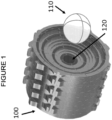
- Figure 1 illustrates an embodiment of the invention wherein a magnet field generating apparatus 100 is placed in proximity to a region of interest 110. As shown in Fig. 1 , there exists an access aperture 120 that is perpendicular to the face of the magnet assembly 100 that is near to the region of interest 110.
- Disclosed embodiments utilize a magnetic field generating apparatus 100 and a radio frequency generating and recording device 130 positioned on one face of the device.
- the magnetic field generating apparatus 100 may be positioned near to only a single face of the region of interest 110.
- the geometrical configuration of the apparatus 100 may include one or more apertures or access holes 120. This configuration enables intervention with the subject, e.g., a human or animal patient/subject can be easily repositioned. Additionally, the one or more apertures or access holes 120 enable increased access to one or more structures in the subject to be imaged.
- the magnetic field generating apparatus 100 may be composed of layers of magnets, one layer of which being composed as illustrated in Figure 2 .
- the layer 200 contains magnets 210 and 220, which are oriented in directions so as to provide magnetic fields opposing the magnetic field provided by a magnet in the same or other layers.
- magnet 210 may be oriented in a position so as to provide a magnetic field opposing the magnetic field produced by magnet 220 in the same layer.
- the aperture is illustrated as aperture 230 in Fig. 2 .
- the magnetic field generating device 100 may include one or more arrays of magnetic components, examples of which being 210 and 220 in one or more layers (an example of which being 200).
- these layers may generate a desired magnetic profile that is either uniform in magnetic field strength to a certain degree of homogeneity, or with a built in magnetic field gradient that varies linearly in space, or with another well characterized magnetic field profile shape suitable for imaging over a region 110.
- the magnetic profile in region 110 may be uniform.
- the magnetic profile in region 110 may not be uniform, in which case an appropriate algorithm for reconstruction may be used to generate an image.
- An example of such an algorithm was provided by Dominic Holland et al. published in the journal Neuroimage volume 50, pages 175-183 in 2010, entitled “Efficient correction of inhomogeneous static magnetic field-induced distortion in Echo Planar Imaging ". Other correction methods may be applied, for example using maximum likelihood reconstructions.
- generation of the magnetic profile may be performed in accordance with patented innovations for imaging of living tissue.
- the imaging system 130 may include electrical coils and/or electro-permanent magnets, in which the electro-permanent magnets that are magnetized by a transient current flowing through electrical coils and stay activated until the magnetization is removed by other transient currents flowing through electrical coils.
- Radiofrequency, gradient, pre-polarizing and/or shimming coils that may be needed to form an image may also be included.
- ultra-fast and high-magnitude gradient pulses as described by Irving Weinberg in US Patent 8154286 , entitled “APPARATUS AND METHOD FOR DECREASING BIO-EFFECTS OF MAGNETIC FIELDS," and related patents and patent applications (related by priority claims) may be used to collect many sets of data points in order to achieve high spatial resolution and signal-to-noise ratio, without causing uncomfortable nerve stimulation.
- Such high magnetic gradient field magnitude may be 400 mT or higher, with rise-times of 10 microseconds or less.
- the gradient pulses may be so rapid as to permit acquisition in a very short time, for example 10 seconds or less, so that there is little motion of the breast during acquisition, thereby reducing resolution loss from "motion-unsharpness.”
- pre-polarizing coils may be activated in order to improve signal-to-noise ratio, as taught in US Patent application 12/488,105 by Weinberg , entitled "RADIOMETAL-LABELED AMINO ACID ANALOGS, IMAGING AND THERAPEUTIC AGENTS INCORPORATING THE SAME, AND METHODS USING THE SAME".
- one or more coils or electro-permanent magnets within the MRI system may be fabricated with additive manufacturing, as taught by Urdaneta et al in the 2011 IEEE Medical Imaging Proceedings entitled “Good-bye Wires and formers: 3-D Additive Manufacturing and Fractal Cooling Applied to Gradient Coils ".
- Magnetic component 210 may be a permanent magnet or may be an electromagnet or may be an electropermanent magnet. Magnetic component 210 may be a discrete magnet or may be a portion of magnetizable material that has been deposited through additive manufacturing and which has been magnetized during or after deposition.
- an electropermanent magnet may be defined as a combination of hard and soft magnetic material with one or more current-carrying coils, in which the electrical current running through the one or more coils magnetizes the soft magnetic component, as disclosed in US Patent Application number 15/427,426 by Weinberg and Nacev , entitled “METHOD AND APPARATUS FOR MANIPULATING ELECTRO-PERMANENT MAGNETS FOR MAGNETIC RESONANCE IMAGING AND IMAGE GUIDED THERAPY".
- the terms "hard magnetic material” and "soft magnetic material” are used to describe material with varying levels of magnetic coercivity, with the hard magnetic material having a higher magnetic coercivity than the soft magnetic material.
- opposite orientation means an orientation that is not parallel to another orientation. It is understood that the invention can be used in conjunction with other components, for example a generator of radiofrequency electromagnetic fields, to create magnetic resonance images of subjects or structures in a region of interest 110. It is understood that some or all of those subjects or structures may be part or all of a living animal or person or inanimate object. It is understood that interventions such as biopsy or therapy may be carried out in part or wholly using the aperture 120.
- device 100 may be used in conjunction with other components, for example a computer and/or a power supply and/or coils for generating magnetic and/or electromagnetic fields, in order to attain a desired result of a meaningful image.
- the image may use principles of proton magnetic resonance imaging, or magnetic resonance imaging of other particles (for example electrons or sodium atoms) or other imaging principles (for example magnetic particle imaging, or impedance imaging).
- the apparatus may be used to deliver therapy by manipulating magnetizable materials with the magnetic field produced by the device. It is understood that said manipulation may be performed at one time, and that imaging may be performed at another time, in order to guide said manipulation.
- the term imaging includes imaging technology that utilize components to form an image using magnetic resonance or magnetic particle imaging. It should be understood that such components include coils or magnets (or electro-permanent magnets) that polarize protons or other nuclei or electrons in one or more structures to be imaged, wherein gradient and/or radiofrequency coils form an image.
- the disclosed embodiments may be used in conjunction with a support structure that may hold an imaging system and may contain other components needed to operate or move the imaging system, for example, wheels and/or batteries.
- an associated display system is not shown but should be understood to be present in order to view images produced by the imaging system.
- disclosed embodiments may image one or more structures for segments of the one or more structure at a time, since it may be difficult in a single-sided MRI to obtain very good uniformity over the entirety of a structure to be imaged. It should be understood that the spatial resolution of certain portions of one or more structures to be imaged, e.g., breast tissues, may be different than in other portions, depending on the gradient applied at the time of image acquisition, which may be useful in order to better characterize certain regions of tissues.
- control and cooperation of the above-described components may be provided using software instructions that may be stored in a tangible, non-transitory storage device such as a non-transitory computer readable storage device storing instructions which, when executed on one or more programmed processors, carry out the above-described method operations and resulting functionality.
- a tangible, non-transitory storage device such as a non-transitory computer readable storage device storing instructions which, when executed on one or more programmed processors, carry out the above-described method operations and resulting functionality.
- non-transitory is intended to preclude transmitted signals and propagating waves, but not storage devices that are erasable or dependent upon power sources to retain information.
Landscapes
- Physics & Mathematics (AREA)
- Health & Medical Sciences (AREA)
- Life Sciences & Earth Sciences (AREA)
- Condensed Matter Physics & Semiconductors (AREA)
- General Physics & Mathematics (AREA)
- General Health & Medical Sciences (AREA)
- Molecular Biology (AREA)
- Veterinary Medicine (AREA)
- Engineering & Computer Science (AREA)
- Biomedical Technology (AREA)
- Heart & Thoracic Surgery (AREA)
- Medical Informatics (AREA)
- Biophysics (AREA)
- Surgery (AREA)
- Animal Behavior & Ethology (AREA)
- Pathology (AREA)
- Public Health (AREA)
- Vascular Medicine (AREA)
- General Life Sciences & Earth Sciences (AREA)
- Physical Education & Sports Medicine (AREA)
- Nuclear Medicine, Radiotherapy & Molecular Imaging (AREA)
- Radiology & Medical Imaging (AREA)
- Electromagnetism (AREA)
- Magnetic Resonance Imaging Apparatus (AREA)
- High Energy & Nuclear Physics (AREA)
Description
- Disclosed embodiments provide a method and apparatus for single-sided magnetic resonance imaging.
- In conventional Magnetic Resonance Imaging (MRI) scanners, the magnetic field used to generate the image is created by a device that is located around the subject. For the purposes of this specification, the term "subject" is understood to be a human or other animal with or without illness. For example, a super conducting clinical MRI usually consists of a superconducting solenoid whose bore becomes the imaging volume. The subject, or patient, is guided into the bore where all imaging is conducted. However, due to the limited size of the bore, these MRI systems restrict patient mobility and can inhibit the permissible patient body sizes that can be imaged.
- To enable greater patient mobility and flexibility, open MRI systems have been developed. These typically consist of bi-planar magnetic field generating components which create a magnetic field within the gap of the two planes. The patient is again imaged within the gap. Typically, the gap distance in these systems is larger than the solenoid configuration of superconducting magnets, but the patient is still enclosed by the MR system.
-
US 2004/ 0066194 relates to magnetic field generating assemblies and methods for use in magnetic resonance and in particular to "inside-out" Nuclear Magnetic Resonance (NMR or MR) instrumentation for use in non-invasive investigation of material properties. It discloses embodiments relating to MR imaging in which the pre-polarization method is combined with open-access magnet designs suitable for MRI. A method and apparatus disclosed allows the current in some winding sections of the magnet to be changed to temporarily re-configure the magnet geometry (magnetic circuit) so that the magnetic field strength in the sample during the pre-polarization period is increased, without increasing the stored magnetic energy in the magnet. - Disclosed embodiments in
US 2017/0139024 enable magnetic resonance imaging using magnetizable nanoparticles. - The independent claims define the scope and dependent claims define different embodiments.
- Disclosed embodiments provide a new imaging apparatus and methodologies to image a subject using an MRI, wherein the imaging apparatus contains only a single sided device for the purposes of imaging structures in the subject. For the purposes of this specification, the terms "single sided device" and "single-sided device" are understood to mean a device placed less than 360 degrees around a subject in order to operate. For example, a conventional cylindrical MRI bore would not be considered a single-sided device.
- In accordance with at least one embodiment, such an apparatus and corresponding methodologies may be used to image, for example, the pelvic region of a subject.
- In accordance with disclosed embodiments, due to the non-encompassing geometry of the innovative imaging apparatus, the subject's mobility is less restricted compared to conventional MRI scanners.
- In accordance with disclosed embodiments, a single-sided MRI system is provided that includes access apertures through which interventions on the subject can be made. For the purposes of this specification, the term "intervention" is understood to be a biopsy or method of treatment involving physical access to a part of the subject.
- The detailed description particularly refers to the accompanying figures in which:
-
Figure 1 shows an embodiment of the disclosed invention, in which a magnet field generating apparatus is placed in proximity to a region of interest. -
Figure 2 shows an example of a composition of one layer of a magnetic field generating apparatus composed of layers of magnets in accordance with a disclosed embodiment. - Conventional single-sided MRI systems do not provide access apertures through which interventions could be made. Examples of such conventional systems include
US Patent 4,721,914 to Eiichi Fukushima , entitled "Apparatus for Unilateral Generation of a Homogeneous Magnetic Field", andUS Patent 6,489,872 by the same inventor, entitled "Unilateral Magnet Having a Remote Uniform Field Region for Nuclear Magnetic Resonance". - To the contrary, in accordance with disclosed embodiments, a single-sided MRI system is provided that includes access apertures through which interventions on the subject can be made.
Figure 1 illustrates an embodiment of the invention wherein a magnetfield generating apparatus 100 is placed in proximity to a region ofinterest 110. As shown inFig. 1 , there exists anaccess aperture 120 that is perpendicular to the face of themagnet assembly 100 that is near to the region ofinterest 110. - Disclosed embodiments utilize a magnetic
field generating apparatus 100 and a radio frequency generating and recording device 130 positioned on one face of the device. The magneticfield generating apparatus 100 may be positioned near to only a single face of the region ofinterest 110. The geometrical configuration of theapparatus 100 may include one or more apertures oraccess holes 120. This configuration enables intervention with the subject, e.g., a human or animal patient/subject can be easily repositioned. Additionally, the one or more apertures oraccess holes 120 enable increased access to one or more structures in the subject to be imaged. - The magnetic
field generating apparatus 100 may be composed of layers of magnets, one layer of which being composed as illustrated inFigure 2 . As shown inFig. 2 , thelayer 200 containsmagnets Fig. 2 ,magnet 210 may be oriented in a position so as to provide a magnetic field opposing the magnetic field produced bymagnet 220 in the same layer. The aperture is illustrated asaperture 230 inFig. 2 . - In accordance with disclosed embodiments, the magnetic
field generating device 100 may include one or more arrays of magnetic components, examples of which being 210 and 220 in one or more layers (an example of which being 200). - These layers may generate a desired magnetic profile that is either uniform in magnetic field strength to a certain degree of homogeneity, or with a built in magnetic field gradient that varies linearly in space, or with another well characterized magnetic field profile shape suitable for imaging over a
region 110. In accordance with at least one embodiment, the magnetic profile inregion 110 may be uniform. Alternatively, in accordance with at least one embodiment, the magnetic profile inregion 110 may not be uniform, in which case an appropriate algorithm for reconstruction may be used to generate an image. An example of such an algorithm was provided by Dominic Holland et al. published in the journal Neuroimage volume 50, pages 175-183 in 2010, entitled "Efficient correction of inhomogeneous static magnetic field-induced distortion in Echo Planar Imaging". Other correction methods may be applied, for example using maximum likelihood reconstructions. Likewise, generation of the magnetic profile may be performed in accordance with patented innovations for imaging of living tissue. - More specifically, the imaging system 130 may include electrical coils and/or electro-permanent magnets, in which the electro-permanent magnets that are magnetized by a transient current flowing through electrical coils and stay activated until the magnetization is removed by other transient currents flowing through electrical coils. Radiofrequency, gradient, pre-polarizing and/or shimming coils that may be needed to form an image may also be included.
- Optionally, ultra-fast and high-magnitude gradient pulses as described by Irving Weinberg in
US Patent 8154286 , entitled "APPARATUS AND METHOD FOR DECREASING BIO-EFFECTS OF MAGNETIC FIELDS," and related patents and patent applications (related by priority claims) may be used to collect many sets of data points in order to achieve high spatial resolution and signal-to-noise ratio, without causing uncomfortable nerve stimulation. Such high magnetic gradient field magnitude may be 400 mT or higher, with rise-times of 10 microseconds or less. The gradient pulses may be so rapid as to permit acquisition in a very short time, for example 10 seconds or less, so that there is little motion of the breast during acquisition, thereby reducing resolution loss from "motion-unsharpness." - Optionally, in accordance with at least one embodiment, pre-polarizing coils may be activated in order to improve signal-to-noise ratio, as taught in
US Patent application 12/488,105 by Weinberg , entitled "RADIOMETAL-LABELED AMINO ACID ANALOGS, IMAGING AND THERAPEUTIC AGENTS INCORPORATING THE SAME, AND METHODS USING THE SAME". - In accodance with at least one embodiment, one or more coils or electro-permanent magnets within the MRI system may be fabricated with additive manufacturing, as taught by Urdaneta et al in the 2011 IEEE Medical Imaging Proceedings entitled "Good-bye Wires and Formers: 3-D Additive Manufacturing and Fractal Cooling Applied to Gradient Coils".
- The
region 110 of desired magnetic profile on one side of the apparatus may not be adjacent to the apparatus, for example it may be one to one hundred centimeters away from theapparatus 100.Magnetic component 210 may be a permanent magnet or may be an electromagnet or may be an electropermanent magnet.Magnetic component 210 may be a discrete magnet or may be a portion of magnetizable material that has been deposited through additive manufacturing and which has been magnetized during or after deposition. - For the purposes of this disclosure an electropermanent magnet may be defined as a combination of hard and soft magnetic material with one or more current-carrying coils, in which the electrical current running through the one or more coils magnetizes the soft magnetic component, as disclosed in
US Patent Application number 15/427,426 by Weinberg and Nacev , entitled "METHOD AND APPARATUS FOR MANIPULATING ELECTRO-PERMANENT MAGNETS FOR MAGNETIC RESONANCE IMAGING AND IMAGE GUIDED THERAPY". In this specification, the terms "hard magnetic material" and "soft magnetic material" are used to describe material with varying levels of magnetic coercivity, with the hard magnetic material having a higher magnetic coercivity than the soft magnetic material. It is understood that what we would term "soft magnetic materials" (e.g. Alnico) for purposes of this specification might be considered as "hard magnetic materials" in comparison to some other materials (for example, Permalloy) by certain authorities. Therefore, the terms "hard magnetic material" and "soft magnetic material" are used to illustrate generally many different materials, without specific limitation as to whether the material is universally considered as being "hard" or "soft". - For the purposes of this disclosure, the term "opposing orientation" means an orientation that is not parallel to another orientation. It is understood that the invention can be used in conjunction with other components, for example a generator of radiofrequency electromagnetic fields, to create magnetic resonance images of subjects or structures in a region of
interest 110. It is understood that some or all of those subjects or structures may be part or all of a living animal or person or inanimate object. It is understood that interventions such as biopsy or therapy may be carried out in part or wholly using theaperture 120. - It is understood that
device 100 may be used in conjunction with other components, for example a computer and/or a power supply and/or coils for generating magnetic and/or electromagnetic fields, in order to attain a desired result of a meaningful image. It is understood that the image may use principles of proton magnetic resonance imaging, or magnetic resonance imaging of other particles (for example electrons or sodium atoms) or other imaging principles (for example magnetic particle imaging, or impedance imaging). It is understood that the apparatus may be used to deliver therapy by manipulating magnetizable materials with the magnetic field produced by the device. It is understood that said manipulation may be performed at one time, and that imaging may be performed at another time, in order to guide said manipulation. - For the purpose of the disclosed embodiments, the term imaging, includes imaging technology that utilize components to form an image using magnetic resonance or magnetic particle imaging. It should be understood that such components include coils or magnets (or electro-permanent magnets) that polarize protons or other nuclei or electrons in one or more structures to be imaged, wherein gradient and/or radiofrequency coils form an image. Thus, although not shown in detail herein, it should be understood that the disclosed embodiments may be used in conjunction with a support structure that may hold an imaging system and may contain other components needed to operate or move the imaging system, for example, wheels and/or batteries.
- Moreover, it should be understood that an associated display system is not shown but should be understood to be present in order to view images produced by the imaging system.
- Further, it should be understood that disclosed embodiments may image one or more structures for segments of the one or more structure at a time, since it may be difficult in a single-sided MRI to obtain very good uniformity over the entirety of a structure to be imaged. It should be understood that the spatial resolution of certain portions of one or more structures to be imaged, e.g., breast tissues, may be different than in other portions, depending on the gradient applied at the time of image acquisition, which may be useful in order to better characterize certain regions of tissues.
- It should be understood that the operations explained herein may be implemented in conjunction with, or under the control of, one or more general purpose computers running software algorithms to provide the presently disclosed functionality and turning those computers into specific purpose computers.
- Moreover, those skilled in the art will recognize, upon consideration of the above teachings, that the above exemplary embodiments may be based upon use of one or more programmed processors programmed with a suitable computer program. However, the disclosed embodiments could be implemented using hardware component equivalents such as special purpose hardware and/or dedicated processors. Similarly, general purpose computers, microprocessor based computers, micro-controllers, optical computers, analog computers, dedicated processors, application specific circuits and/or dedicated hard wired logic may be used to construct alternative equivalent embodiments.
- Moreover, it should be understood that control and cooperation of the above-described components may be provided using software instructions that may be stored in a tangible, non-transitory storage device such as a non-transitory computer readable storage device storing instructions which, when executed on one or more programmed processors, carry out the above-described method operations and resulting functionality. In this case, the term non-transitory is intended to preclude transmitted signals and propagating waves, but not storage devices that are erasable or dependent upon power sources to retain information.
- Those skilled in the art will appreciate, upon consideration of the above teachings, that the program operations and processes and associated data used to implement certain of the embodiments described above can be implemented using disc storage as well as other forms of storage devices including, but not limited to non-transitory storage media (where non-transitory is intended only to preclude propagating signals and not signals which are transitory in that they are erased by removal of power or explicit acts of erasure) such as for example Read Only Memory (ROM) devices, Random Access Memory (RAM) devices, network memory devices, optical storage elements, magnetic storage elements, magneto-optical storage elements, flash memory, core memory and/or other equivalent volatile and non-volatile storage technologies without departing from certain embodiments. Such alternative storage devices should be considered equivalents.
- While certain illustrative embodiments have been described, it is evident that many alternatives, modifications, permutations and variations will become apparent to those skilled in the art in light of the foregoing description. Accordingly, the various embodiments of, as set forth above, are intended to be illustrative, not limiting.
Claims (6)
- A single-sided magnetic resonance apparatus (100) for imaging one or more structures included in a subject, the apparatus comprising:one or more arrays (210, 220) of magnetic components comprised in one or more layers (200) to generate a magnetic field on one side of the apparatus (100), said magnetic field having a well characterized magnetic field profile suitable for imaging over a region, the magnetic components being permanent magnets or electromagnets or electropermanent magnets, whereby each electropermanent magnet is a combination of hard and soft magnetic materials with one or more current-carrying coils configured to magnetize the soft magnetic material, wherein some of the magnetic components (210) in a layer are oriented in directions so as to provide magnetic fields opposing the magnetic field provided by other magnetic components (220) of the magnetic components in the same or other layers; andan access aperture (230) provided through the magnetic components enabling intervention with the subject of the imaging,wherein the subject is a living animal or a person.
- The imaging apparatus (100) of claim 1, wherein the apparatus (100) is configured to image the pelvic region of the subject.
- The imaging apparatus (100) of claim 1, wherein an axis of the access aperture (230) is perpendicular to a face of the imaging apparatus.
- A method of using a single-sided magnetic resonance apparatus (100) according to claim 1 for imaging one or more structures included in a subject, the method comprising:positioning the single-sided magnetic resonance apparatus (100), such that the one or more structures of the subject is in the region where the magnetic field has the well characterized magnetic field profile suitable for imaging; andimaging the one or more structures using magnetic resonance imaging using the single-sided magnetic resonance apparatus (100),wherein the subject is a living animal or person.
- The imaging method of claim 4, wherein the pelvic region of the subject is imaged.
- The imaging method of claim 4, wherein an axis of the access aperture (230) is perpendicular to a face of the imaging apparatus (100).
Applications Claiming Priority (2)
| Application Number | Priority Date | Filing Date | Title |
|---|---|---|---|
| US201762516698P | 2017-06-08 | 2017-06-08 | |
| PCT/US2018/036686 WO2018227108A1 (en) | 2017-06-08 | 2018-06-08 | Unilateral magnetic resonance imaging system with aperture for interventions and methodologies for operating same |
Publications (3)
| Publication Number | Publication Date |
|---|---|
| EP3634235A1 EP3634235A1 (en) | 2020-04-15 |
| EP3634235A4 EP3634235A4 (en) | 2020-06-24 |
| EP3634235B1 true EP3634235B1 (en) | 2024-11-20 |
Family
ID=64564063
Family Applications (1)
| Application Number | Title | Priority Date | Filing Date |
|---|---|---|---|
| EP18812673.4A Active EP3634235B1 (en) | 2017-06-08 | 2018-06-08 | Unilateral magnetic resonance imaging system with aperture for interventions and methodologies for operating same |
Country Status (9)
| Country | Link |
|---|---|
| US (1) | US11686793B2 (en) |
| EP (1) | EP3634235B1 (en) |
| JP (2) | JP2020523172A (en) |
| KR (1) | KR102516329B1 (en) |
| CN (1) | CN110719753B (en) |
| AU (1) | AU2018279823B2 (en) |
| ES (1) | ES2999763T3 (en) |
| SG (1) | SG11201911699PA (en) |
| WO (1) | WO2018227108A1 (en) |
Families Citing this family (14)
| Publication number | Priority date | Publication date | Assignee | Title |
|---|---|---|---|---|
| AU2020223171B2 (en) | 2019-02-15 | 2025-11-27 | Promaxo, Inc. | Systems and methods for ultralow field relaxation dispersion |
| US11656303B2 (en) | 2019-02-22 | 2023-05-23 | Promaxo, Inc. | Pseudo-birdcage coil with variable tuning and applications thereof |
| AU2020225653A1 (en) * | 2019-02-22 | 2021-09-16 | Promaxo, Inc. | Systems and methods for performing magnetic resonance imaging |
| IL297126B2 (en) | 2019-03-25 | 2025-02-01 | Promaxo Inc | Systems and methods for volumetric acquisition in a single-sided mri system |
| EP3948323A4 (en) * | 2019-03-25 | 2022-12-21 | Promaxo, Inc. | FAST SINGLE-SIDED MRI FIELD-GRADIENT COILS AND THEIR APPLICATIONS |
| CN115209829B (en) * | 2020-01-23 | 2025-10-24 | 普罗马克索公司 | MRI-guided robotic systems and methods for biopsy |
| KR20220164825A (en) * | 2020-02-20 | 2022-12-13 | 프로맥소 인크. | A radio frequency receiving coil network for cross-sectional magnetic resonance imaging |
| MX2022011198A (en) * | 2020-03-09 | 2022-09-19 | Promaxo Inc | Phase encoding with frequency sweep pulsed for magnetic resonance imaging in inhomogeneous magnetic fields. |
| CA3171251A1 (en) | 2020-03-09 | 2021-09-16 | Muller Francis DE MATOS GOMES | Pulse sequences and frequency sweep pulses for single-sided magnetic resonance imaging |
| EP4330699B1 (en) | 2021-04-26 | 2025-07-09 | Promaxo, Inc. | Interventional localization guide and method for mri guided pelvic interventions |
| EP4334732A1 (en) * | 2021-05-05 | 2024-03-13 | Neuro42 Inc. | Neural interventional magnetic resonance imaging apparatus |
| EP4113146B1 (en) * | 2021-06-30 | 2025-05-07 | Siemens Healthineers AG | Magnetic resonance imaging device with a concave-shaped field generation unit |
| EP4460704A1 (en) | 2022-01-04 | 2024-11-13 | Promaxo, Inc. | Relaxation-based magnetic resonance thermometry with a low-field single-sided mri scanner |
| WO2025230012A1 (en) * | 2024-05-02 | 2025-11-06 | 国立大学法人千葉大学 | Magnetic resonance detector and magnetic resonance probe |
Family Cites Families (24)
| Publication number | Priority date | Publication date | Assignee | Title |
|---|---|---|---|---|
| US4721914A (en) | 1984-05-01 | 1988-01-26 | The United States Of America As Represented By The United States Department Of Energy | Apparatus for unilateral generation of a homogeneous magnetic field |
| US5382904A (en) * | 1992-04-15 | 1995-01-17 | Houston Advanced Research Center | Structured coil electromagnets for magnetic resonance imaging and method for fabricating the same |
| US5900793A (en) * | 1997-07-23 | 1999-05-04 | Odin Technologies Ltd | Permanent magnet assemblies for use in medical applications |
| ATE419789T1 (en) * | 1997-05-23 | 2009-01-15 | Prorhythm Inc | HIGH INTENSITY DISPOSABLE FOCUSING ULTRASONIC APPLICATOR |
| US6489872B1 (en) | 1999-05-06 | 2002-12-03 | New Mexico Resonance | Unilateral magnet having a remote uniform field region for nuclear magnetic resonance |
| US6262576B1 (en) * | 1999-11-16 | 2001-07-17 | Picker International, Inc. | Phased array planar gradient coil set for MRI systems |
| US20040066194A1 (en) * | 2001-01-12 | 2004-04-08 | Slade Robert Andrew | Magnetic field generating assembly and method |
| JP2002325743A (en) | 2001-05-02 | 2002-11-12 | Shin Etsu Chem Co Ltd | Magnetic circuit structure for MRI |
| US7970452B2 (en) * | 2003-09-30 | 2011-06-28 | Hologic, Inc. | Open architecture imaging apparatus and coil system for magnetic resonance imaging |
| US7379769B2 (en) | 2003-09-30 | 2008-05-27 | Sunnybrook Health Sciences Center | Hybrid imaging method to monitor medical device delivery and patient support for use in the method |
| DE102005024479B3 (en) * | 2005-05-24 | 2006-11-30 | Bruker Biospin Gmbh | Testing head for nuclear resonance measurements comprises a screen arranged between units for producing a high frequency magnetic field and the surface of an object being tested |
| JP5170617B2 (en) * | 2007-04-24 | 2013-03-27 | 独立行政法人産業技術総合研究所 | Open circuit on one side |
| EP2197534B1 (en) * | 2007-09-25 | 2018-03-07 | Neosync, INC. | Device with two rotatable permanent magnets for application to the head of a subject |
| ES2907993T3 (en) | 2008-06-20 | 2022-04-27 | Irving Weinberg | Procedure to reduce the biological effects of magnetic field gradients |
| CN101430371B (en) * | 2008-12-19 | 2012-07-18 | 中国科学院电工研究所 | Magnetic resonance imaging method and apparatus thereof |
| US20120010497A1 (en) | 2009-04-02 | 2012-01-12 | Ehman Richard L | Single-Sided Magnetic Resonance Imaging System Suitable for Performing Magnetic Resonance Elastography |
| EP2500742A1 (en) * | 2011-03-17 | 2012-09-19 | Koninklijke Philips Electronics N.V. | Restriction of the imaging region for MRI in an inhomogeneous magnetic field |
| US20120265050A1 (en) * | 2011-04-04 | 2012-10-18 | Ge Wang | Omni-Tomographic Imaging for Interior Reconstruction using Simultaneous Data Acquisition from Multiple Imaging Modalities |
| US9330825B2 (en) * | 2011-04-12 | 2016-05-03 | Mohammad Sarai | Magnetic configurations |
| CN104181480B (en) * | 2013-05-21 | 2017-02-08 | 上海联影医疗科技有限公司 | Method and system for measuring and correcting imaging magnetic field in magnetic resonance device |
| US20150112187A1 (en) * | 2013-10-18 | 2015-04-23 | Imris Inc. | MR Imaging with RF Coil Integrated into Patient Engaging Component |
| US10534053B2 (en) * | 2015-11-16 | 2020-01-14 | Weinberg Medical Physics, Inc. | Method and apparatus for high slew rate single point magnetic resonance imaging of magnetizable nanoparticles |
| US20170227617A1 (en) | 2016-02-09 | 2017-08-10 | Weinberg Medical Physics, Inc. | Method and apparatus for manipulating electropermanent magnets for magnetic resonance imaging and image guided therapy |
| US10823793B2 (en) * | 2019-03-27 | 2020-11-03 | Siemens Healthcare Gmbh | Resonance data acquisition scanner with rotating basic field magnet |
-
2018
- 2018-06-08 AU AU2018279823A patent/AU2018279823B2/en active Active
- 2018-06-08 JP JP2020517768A patent/JP2020523172A/en active Pending
- 2018-06-08 EP EP18812673.4A patent/EP3634235B1/en active Active
- 2018-06-08 ES ES18812673T patent/ES2999763T3/en active Active
- 2018-06-08 SG SG11201911699PA patent/SG11201911699PA/en unknown
- 2018-06-08 US US16/003,585 patent/US11686793B2/en active Active
- 2018-06-08 WO PCT/US2018/036686 patent/WO2018227108A1/en not_active Ceased
- 2018-06-08 KR KR1020197038970A patent/KR102516329B1/en active Active
- 2018-06-08 CN CN201880038263.8A patent/CN110719753B/en active Active
-
2023
- 2023-12-07 JP JP2023206854A patent/JP7638358B2/en active Active
Also Published As
| Publication number | Publication date |
|---|---|
| EP3634235A1 (en) | 2020-04-15 |
| CN110719753A (en) | 2020-01-21 |
| US11686793B2 (en) | 2023-06-27 |
| JP2024037819A (en) | 2024-03-19 |
| AU2018279823A1 (en) | 2020-01-16 |
| JP2020523172A (en) | 2020-08-06 |
| WO2018227108A1 (en) | 2018-12-13 |
| ES2999763T3 (en) | 2025-02-26 |
| US20180356480A1 (en) | 2018-12-13 |
| KR102516329B1 (en) | 2023-03-30 |
| AU2018279823B2 (en) | 2024-03-28 |
| SG11201911699PA (en) | 2020-01-30 |
| CN110719753B (en) | 2025-08-08 |
| JP7638358B2 (en) | 2025-03-03 |
| EP3634235A4 (en) | 2020-06-24 |
| KR20200018510A (en) | 2020-02-19 |
Similar Documents
| Publication | Publication Date | Title |
|---|---|---|
| AU2018279823B2 (en) | Unilateral magnetic resonance imaging system with aperture for interventions and methodologies for operating same | |
| Marques et al. | Low‐field MRI: an MR physics perspective | |
| JP6317341B2 (en) | Portable magnetic resonance imaging system and method using rotating array permanent magnets | |
| US11675034B2 (en) | Magnetic resonance scanner and magnetic resonance imaging system | |
| CN104619249B (en) | Device for producing the Distribution of Magnetic Field for meeting MPI and MRI requirements | |
| CN110632540B (en) | Method for obtaining images and manipulating objects using magnetic gradients generated by one or more electropermanent magnet arrays | |
| US11448715B2 (en) | Permanent magnet system and method of forming thereof | |
| JP3856505B2 (en) | Magnetic resonance imaging system | |
| US20080097189A1 (en) | Combined MR imaging and tracking | |
| CN120993296A (en) | Magnetic resonance device | |
| de Lara et al. | Simulations of a birdcage coil B 1+ field on a human body model for designing a 3T multichannel TMS/MRI head coil array | |
| JP4045769B2 (en) | Magnetic field generator and MRI apparatus using the same | |
| US11378632B2 (en) | Apparatus and method for rapid and comfortable magnetic imaging of breast tissues, with cultural sensitivity | |
| Wong et al. | Shimming of the inferior frontal cortex using an external local shim coil | |
| Jakob | Small animal magnetic resonance imaging: basic principles, instrumentation and practical issue | |
| Prost et al. | How does an MR scanner operate? | |
| KR20240114530A (en) | Imaging Apparatus for Integrating Magnetic Particle Imaging and Magnetic Resonance Imaging and Method therein | |
| Shen | Magnet Design for LFEIT | |
| GB2525209A (en) | MRI Apparatus and methods | |
| Ireland | Radiofrequency Coils for Faster and Quieter MR Imaging on a Neonatal MR System | |
| CN116087849A (en) | Gradient coil special for MRI | |
| Adkisson | An Introduction to Magnetic Resonance Imaging Physics | |
| Burgess | Magnetic resonance imaging at ultra high field: implications for human neuroimaging | |
| Oldendorf et al. | The MRI Scanner | |
| GB2422672A (en) | A solenoidal magnet structure for a magnetic resonance imaging system |
Legal Events
| Date | Code | Title | Description |
|---|---|---|---|
| STAA | Information on the status of an ep patent application or granted ep patent |
Free format text: STATUS: THE INTERNATIONAL PUBLICATION HAS BEEN MADE |
|
| PUAI | Public reference made under article 153(3) epc to a published international application that has entered the european phase |
Free format text: ORIGINAL CODE: 0009012 |
|
| STAA | Information on the status of an ep patent application or granted ep patent |
Free format text: STATUS: REQUEST FOR EXAMINATION WAS MADE |
|
| 17P | Request for examination filed |
Effective date: 20200103 |
|
| AK | Designated contracting states |
Kind code of ref document: A1 Designated state(s): AL AT BE BG CH CY CZ DE DK EE ES FI FR GB GR HR HU IE IS IT LI LT LU LV MC MK MT NL NO PL PT RO RS SE SI SK SM TR |
|
| AX | Request for extension of the european patent |
Extension state: BA ME |
|
| A4 | Supplementary search report drawn up and despatched |
Effective date: 20200528 |
|
| RIC1 | Information provided on ipc code assigned before grant |
Ipc: A61B 5/00 20060101ALI20200520BHEP Ipc: G01R 33/383 20060101ALN20200520BHEP Ipc: A61B 5/055 20060101ALI20200520BHEP Ipc: G01R 33/38 20060101AFI20200520BHEP |
|
| DAV | Request for validation of the european patent (deleted) | ||
| DAX | Request for extension of the european patent (deleted) | ||
| STAA | Information on the status of an ep patent application or granted ep patent |
Free format text: STATUS: EXAMINATION IS IN PROGRESS |
|
| 17Q | First examination report despatched |
Effective date: 20221129 |
|
| REG | Reference to a national code |
Ref country code: DE Ref legal event code: R079 Free format text: PREVIOUS MAIN CLASS: A61B0006000000 Ipc: G01R0033380000 Ref country code: DE Ref legal event code: R079 Ref document number: 602018076785 Country of ref document: DE Free format text: PREVIOUS MAIN CLASS: A61B0006000000 Ipc: G01R0033380000 |
|
| RIC1 | Information provided on ipc code assigned before grant |
Ipc: A61B 5/00 20060101ALI20240130BHEP Ipc: A61B 5/055 20060101ALI20240130BHEP Ipc: G01R 33/383 20060101ALI20240130BHEP Ipc: G01R 33/381 20060101ALI20240130BHEP Ipc: G01R 33/38 20060101AFI20240130BHEP |
|
| GRAP | Despatch of communication of intention to grant a patent |
Free format text: ORIGINAL CODE: EPIDOSNIGR1 |
|
| STAA | Information on the status of an ep patent application or granted ep patent |
Free format text: STATUS: GRANT OF PATENT IS INTENDED |
|
| INTG | Intention to grant announced |
Effective date: 20240319 |
|
| GRAS | Grant fee paid |
Free format text: ORIGINAL CODE: EPIDOSNIGR3 |
|
| GRAA | (expected) grant |
Free format text: ORIGINAL CODE: 0009210 |
|
| STAA | Information on the status of an ep patent application or granted ep patent |
Free format text: STATUS: THE PATENT HAS BEEN GRANTED |
|
| AK | Designated contracting states |
Kind code of ref document: B1 Designated state(s): AL AT BE BG CH CY CZ DE DK EE ES FI FR GB GR HR HU IE IS IT LI LT LU LV MC MK MT NL NO PL PT RO RS SE SI SK SM TR |
|
| REG | Reference to a national code |
Ref country code: GB Ref legal event code: FG4D |
|
| REG | Reference to a national code |
Ref country code: CH Ref legal event code: EP |
|
| REG | Reference to a national code |
Ref country code: DE Ref legal event code: R096 Ref document number: 602018076785 Country of ref document: DE |
|
| REG | Reference to a national code |
Ref country code: IE Ref legal event code: FG4D |
|
| REG | Reference to a national code |
Ref country code: SE Ref legal event code: TRGR |
|
| REG | Reference to a national code |
Ref country code: NL Ref legal event code: FP |
|
| REG | Reference to a national code |
Ref country code: ES Ref legal event code: FG2A Ref document number: 2999763 Country of ref document: ES Kind code of ref document: T3 Effective date: 20250226 |
|
| REG | Reference to a national code |
Ref country code: LT Ref legal event code: MG9D |
|
| PG25 | Lapsed in a contracting state [announced via postgrant information from national office to epo] |
Ref country code: PT Free format text: LAPSE BECAUSE OF FAILURE TO SUBMIT A TRANSLATION OF THE DESCRIPTION OR TO PAY THE FEE WITHIN THE PRESCRIBED TIME-LIMIT Effective date: 20250320 Ref country code: HR Free format text: LAPSE BECAUSE OF FAILURE TO SUBMIT A TRANSLATION OF THE DESCRIPTION OR TO PAY THE FEE WITHIN THE PRESCRIBED TIME-LIMIT Effective date: 20241120 Ref country code: IS Free format text: LAPSE BECAUSE OF FAILURE TO SUBMIT A TRANSLATION OF THE DESCRIPTION OR TO PAY THE FEE WITHIN THE PRESCRIBED TIME-LIMIT Effective date: 20250320 |
|
| PG25 | Lapsed in a contracting state [announced via postgrant information from national office to epo] |
Ref country code: FI Free format text: LAPSE BECAUSE OF FAILURE TO SUBMIT A TRANSLATION OF THE DESCRIPTION OR TO PAY THE FEE WITHIN THE PRESCRIBED TIME-LIMIT Effective date: 20241120 |
|
| REG | Reference to a national code |
Ref country code: AT Ref legal event code: MK05 Ref document number: 1744044 Country of ref document: AT Kind code of ref document: T Effective date: 20241120 |
|
| PG25 | Lapsed in a contracting state [announced via postgrant information from national office to epo] |
Ref country code: BG Free format text: LAPSE BECAUSE OF FAILURE TO SUBMIT A TRANSLATION OF THE DESCRIPTION OR TO PAY THE FEE WITHIN THE PRESCRIBED TIME-LIMIT Effective date: 20241120 |
|
| PG25 | Lapsed in a contracting state [announced via postgrant information from national office to epo] |
Ref country code: NO Free format text: LAPSE BECAUSE OF FAILURE TO SUBMIT A TRANSLATION OF THE DESCRIPTION OR TO PAY THE FEE WITHIN THE PRESCRIBED TIME-LIMIT Effective date: 20250220 |
|
| PG25 | Lapsed in a contracting state [announced via postgrant information from national office to epo] |
Ref country code: AT Free format text: LAPSE BECAUSE OF FAILURE TO SUBMIT A TRANSLATION OF THE DESCRIPTION OR TO PAY THE FEE WITHIN THE PRESCRIBED TIME-LIMIT Effective date: 20241120 Ref country code: LV Free format text: LAPSE BECAUSE OF FAILURE TO SUBMIT A TRANSLATION OF THE DESCRIPTION OR TO PAY THE FEE WITHIN THE PRESCRIBED TIME-LIMIT Effective date: 20241120 Ref country code: GR Free format text: LAPSE BECAUSE OF FAILURE TO SUBMIT A TRANSLATION OF THE DESCRIPTION OR TO PAY THE FEE WITHIN THE PRESCRIBED TIME-LIMIT Effective date: 20250221 |
|
| PG25 | Lapsed in a contracting state [announced via postgrant information from national office to epo] |
Ref country code: PL Free format text: LAPSE BECAUSE OF FAILURE TO SUBMIT A TRANSLATION OF THE DESCRIPTION OR TO PAY THE FEE WITHIN THE PRESCRIBED TIME-LIMIT Effective date: 20241120 |
|
| PG25 | Lapsed in a contracting state [announced via postgrant information from national office to epo] |
Ref country code: RS Free format text: LAPSE BECAUSE OF FAILURE TO SUBMIT A TRANSLATION OF THE DESCRIPTION OR TO PAY THE FEE WITHIN THE PRESCRIBED TIME-LIMIT Effective date: 20250220 |
|
| PG25 | Lapsed in a contracting state [announced via postgrant information from national office to epo] |
Ref country code: SM Free format text: LAPSE BECAUSE OF FAILURE TO SUBMIT A TRANSLATION OF THE DESCRIPTION OR TO PAY THE FEE WITHIN THE PRESCRIBED TIME-LIMIT Effective date: 20241120 |
|
| PGFP | Annual fee paid to national office [announced via postgrant information from national office to epo] |
Ref country code: DE Payment date: 20250627 Year of fee payment: 8 |
|
| PG25 | Lapsed in a contracting state [announced via postgrant information from national office to epo] |
Ref country code: DK Free format text: LAPSE BECAUSE OF FAILURE TO SUBMIT A TRANSLATION OF THE DESCRIPTION OR TO PAY THE FEE WITHIN THE PRESCRIBED TIME-LIMIT Effective date: 20241120 |
|
| PGFP | Annual fee paid to national office [announced via postgrant information from national office to epo] |
Ref country code: GB Payment date: 20250627 Year of fee payment: 8 |
|
| PGFP | Annual fee paid to national office [announced via postgrant information from national office to epo] |
Ref country code: LU Payment date: 20250627 Year of fee payment: 8 Ref country code: NL Payment date: 20250626 Year of fee payment: 8 Ref country code: BE Payment date: 20250627 Year of fee payment: 8 |
|
| PG25 | Lapsed in a contracting state [announced via postgrant information from national office to epo] |
Ref country code: EE Free format text: LAPSE BECAUSE OF FAILURE TO SUBMIT A TRANSLATION OF THE DESCRIPTION OR TO PAY THE FEE WITHIN THE PRESCRIBED TIME-LIMIT Effective date: 20241120 |
|
| PGFP | Annual fee paid to national office [announced via postgrant information from national office to epo] |
Ref country code: FR Payment date: 20250625 Year of fee payment: 8 |
|
| PG25 | Lapsed in a contracting state [announced via postgrant information from national office to epo] |
Ref country code: RO Free format text: LAPSE BECAUSE OF FAILURE TO SUBMIT A TRANSLATION OF THE DESCRIPTION OR TO PAY THE FEE WITHIN THE PRESCRIBED TIME-LIMIT Effective date: 20241120 |
|
| PG25 | Lapsed in a contracting state [announced via postgrant information from national office to epo] |
Ref country code: SK Free format text: LAPSE BECAUSE OF FAILURE TO SUBMIT A TRANSLATION OF THE DESCRIPTION OR TO PAY THE FEE WITHIN THE PRESCRIBED TIME-LIMIT Effective date: 20241120 |
|
| PG25 | Lapsed in a contracting state [announced via postgrant information from national office to epo] |
Ref country code: CZ Free format text: LAPSE BECAUSE OF FAILURE TO SUBMIT A TRANSLATION OF THE DESCRIPTION OR TO PAY THE FEE WITHIN THE PRESCRIBED TIME-LIMIT Effective date: 20241120 |
|
| PG25 | Lapsed in a contracting state [announced via postgrant information from national office to epo] |
Ref country code: IT Free format text: LAPSE BECAUSE OF FAILURE TO SUBMIT A TRANSLATION OF THE DESCRIPTION OR TO PAY THE FEE WITHIN THE PRESCRIBED TIME-LIMIT Effective date: 20241120 |
|
| PGFP | Annual fee paid to national office [announced via postgrant information from national office to epo] |
Ref country code: IE Payment date: 20250627 Year of fee payment: 8 |
|
| PGFP | Annual fee paid to national office [announced via postgrant information from national office to epo] |
Ref country code: SE Payment date: 20250626 Year of fee payment: 8 |
|
| REG | Reference to a national code |
Ref country code: DE Ref legal event code: R097 Ref document number: 602018076785 Country of ref document: DE |
|
| PLBE | No opposition filed within time limit |
Free format text: ORIGINAL CODE: 0009261 |
|
| STAA | Information on the status of an ep patent application or granted ep patent |
Free format text: STATUS: NO OPPOSITION FILED WITHIN TIME LIMIT |
|
| PGFP | Annual fee paid to national office [announced via postgrant information from national office to epo] |
Ref country code: ES Payment date: 20250701 Year of fee payment: 8 |
|
| PGFP | Annual fee paid to national office [announced via postgrant information from national office to epo] |
Ref country code: CH Payment date: 20250701 Year of fee payment: 8 |
|
| 26N | No opposition filed |
Effective date: 20250821 |
|
| PG25 | Lapsed in a contracting state [announced via postgrant information from national office to epo] |
Ref country code: MC Free format text: LAPSE BECAUSE OF FAILURE TO SUBMIT A TRANSLATION OF THE DESCRIPTION OR TO PAY THE FEE WITHIN THE PRESCRIBED TIME-LIMIT Effective date: 20241120 |