EP3634097B1 - Terminal and method for retaining a component to a surface, and manufacturing method and apparatus - Google Patents
Terminal and method for retaining a component to a surface, and manufacturing method and apparatus Download PDFInfo
- Publication number
- EP3634097B1 EP3634097B1 EP19200737.5A EP19200737A EP3634097B1 EP 3634097 B1 EP3634097 B1 EP 3634097B1 EP 19200737 A EP19200737 A EP 19200737A EP 3634097 B1 EP3634097 B1 EP 3634097B1
- Authority
- EP
- European Patent Office
- Prior art keywords
- clip
- casing
- shielding
- shielding part
- outwardly extending
- Prior art date
- Legal status (The legal status is an assumption and is not a legal conclusion. Google has not performed a legal analysis and makes no representation as to the accuracy of the status listed.)
- Active
Links
Images





Classifications
-
- H—ELECTRICITY
- H05—ELECTRIC TECHNIQUES NOT OTHERWISE PROVIDED FOR
- H05K—PRINTED CIRCUITS; CASINGS OR CONSTRUCTIONAL DETAILS OF ELECTRIC APPARATUS; MANUFACTURE OF ASSEMBLAGES OF ELECTRICAL COMPONENTS
- H05K9/00—Screening of apparatus or components against electric or magnetic fields
- H05K9/0007—Casings
- H05K9/002—Casings with localised screening
- H05K9/0022—Casings with localised screening of components mounted on printed circuit boards [PCB]
- H05K9/0024—Shield cases mounted on a PCB, e.g. cans or caps or conformal shields
- H05K9/0032—Shield cases mounted on a PCB, e.g. cans or caps or conformal shields having multiple parts, e.g. frames mating with lids
- H05K9/0035—Shield cases mounted on a PCB, e.g. cans or caps or conformal shields having multiple parts, e.g. frames mating with lids with retainers mounted beforehand on the PCB, e.g. clips
-
- H—ELECTRICITY
- H05—ELECTRIC TECHNIQUES NOT OTHERWISE PROVIDED FOR
- H05K—PRINTED CIRCUITS; CASINGS OR CONSTRUCTIONAL DETAILS OF ELECTRIC APPARATUS; MANUFACTURE OF ASSEMBLAGES OF ELECTRICAL COMPONENTS
- H05K3/00—Apparatus or processes for manufacturing printed circuits
- H05K3/30—Assembling printed circuits with electric components, e.g. with resistors
- H05K3/32—Assembling printed circuits with electric components, e.g. with resistors electrically connecting electric components or wires to printed circuits
- H05K3/34—Assembling printed circuits with electric components, e.g. with resistors electrically connecting electric components or wires to printed circuits by soldering
- H05K3/341—Surface mounted components
-
- H—ELECTRICITY
- H05—ELECTRIC TECHNIQUES NOT OTHERWISE PROVIDED FOR
- H05K—PRINTED CIRCUITS; CASINGS OR CONSTRUCTIONAL DETAILS OF ELECTRIC APPARATUS; MANUFACTURE OF ASSEMBLAGES OF ELECTRICAL COMPONENTS
- H05K7/00—Constructional details common to different types of electric apparatus
- H05K7/02—Arrangements of circuit components or wiring on supporting structure
- H05K7/12—Resilient or clamping means for holding component to structure
-
- H—ELECTRICITY
- H05—ELECTRIC TECHNIQUES NOT OTHERWISE PROVIDED FOR
- H05K—PRINTED CIRCUITS; CASINGS OR CONSTRUCTIONAL DETAILS OF ELECTRIC APPARATUS; MANUFACTURE OF ASSEMBLAGES OF ELECTRICAL COMPONENTS
- H05K7/00—Constructional details common to different types of electric apparatus
- H05K7/14—Mounting supporting structure in casing or on frame or rack
- H05K7/1401—Mounting supporting structure in casing or on frame or rack comprising clamping or extracting means
- H05K7/1402—Mounting supporting structure in casing or on frame or rack comprising clamping or extracting means for securing or extracting printed circuit boards
- H05K7/1405—Mounting supporting structure in casing or on frame or rack comprising clamping or extracting means for securing or extracting printed circuit boards by clips or resilient members, e.g. hooks
-
- H—ELECTRICITY
- H05—ELECTRIC TECHNIQUES NOT OTHERWISE PROVIDED FOR
- H05K—PRINTED CIRCUITS; CASINGS OR CONSTRUCTIONAL DETAILS OF ELECTRIC APPARATUS; MANUFACTURE OF ASSEMBLAGES OF ELECTRICAL COMPONENTS
- H05K7/00—Constructional details common to different types of electric apparatus
- H05K7/14—Mounting supporting structure in casing or on frame or rack
- H05K7/1417—Mounting supporting structure in casing or on frame or rack having securing means for mounting boards, plates or wiring boards
-
- H—ELECTRICITY
- H05—ELECTRIC TECHNIQUES NOT OTHERWISE PROVIDED FOR
- H05K—PRINTED CIRCUITS; CASINGS OR CONSTRUCTIONAL DETAILS OF ELECTRIC APPARATUS; MANUFACTURE OF ASSEMBLAGES OF ELECTRICAL COMPONENTS
- H05K9/00—Screening of apparatus or components against electric or magnetic fields
- H05K9/0007—Casings
- H05K9/0009—Casings with provisions to reduce EMI leakage through the joining parts
-
- H—ELECTRICITY
- H05—ELECTRIC TECHNIQUES NOT OTHERWISE PROVIDED FOR
- H05K—PRINTED CIRCUITS; CASINGS OR CONSTRUCTIONAL DETAILS OF ELECTRIC APPARATUS; MANUFACTURE OF ASSEMBLAGES OF ELECTRICAL COMPONENTS
- H05K9/00—Screening of apparatus or components against electric or magnetic fields
- H05K9/0007—Casings
- H05K9/002—Casings with localised screening
- H05K9/0022—Casings with localised screening of components mounted on printed circuit boards [PCB]
- H05K9/0024—Shield cases mounted on a PCB, e.g. cans or caps or conformal shields
- H05K9/0026—Shield cases mounted on a PCB, e.g. cans or caps or conformal shields integrally formed from metal sheet
- H05K9/0028—Shield cases mounted on a PCB, e.g. cans or caps or conformal shields integrally formed from metal sheet with retainers or specific soldering features
-
- H—ELECTRICITY
- H05—ELECTRIC TECHNIQUES NOT OTHERWISE PROVIDED FOR
- H05K—PRINTED CIRCUITS; CASINGS OR CONSTRUCTIONAL DETAILS OF ELECTRIC APPARATUS; MANUFACTURE OF ASSEMBLAGES OF ELECTRICAL COMPONENTS
- H05K1/00—Printed circuits
- H05K1/02—Details
- H05K1/0213—Electrical arrangements not otherwise provided for
- H05K1/0216—Reduction of cross-talk, noise or electromagnetic interference
-
- H—ELECTRICITY
- H05—ELECTRIC TECHNIQUES NOT OTHERWISE PROVIDED FOR
- H05K—PRINTED CIRCUITS; CASINGS OR CONSTRUCTIONAL DETAILS OF ELECTRIC APPARATUS; MANUFACTURE OF ASSEMBLAGES OF ELECTRICAL COMPONENTS
- H05K2201/00—Indexing scheme relating to printed circuits covered by H05K1/00
- H05K2201/10—Details of components or other objects attached to or integrated in a printed circuit board
- H05K2201/10227—Other objects, e.g. metallic pieces
- H05K2201/1031—Surface mounted metallic connector elements
-
- H—ELECTRICITY
- H05—ELECTRIC TECHNIQUES NOT OTHERWISE PROVIDED FOR
- H05K—PRINTED CIRCUITS; CASINGS OR CONSTRUCTIONAL DETAILS OF ELECTRIC APPARATUS; MANUFACTURE OF ASSEMBLAGES OF ELECTRICAL COMPONENTS
- H05K2201/00—Indexing scheme relating to printed circuits covered by H05K1/00
- H05K2201/10—Details of components or other objects attached to or integrated in a printed circuit board
- H05K2201/10227—Other objects, e.g. metallic pieces
- H05K2201/10371—Shields or metal cases
-
- H—ELECTRICITY
- H05—ELECTRIC TECHNIQUES NOT OTHERWISE PROVIDED FOR
- H05K—PRINTED CIRCUITS; CASINGS OR CONSTRUCTIONAL DETAILS OF ELECTRIC APPARATUS; MANUFACTURE OF ASSEMBLAGES OF ELECTRICAL COMPONENTS
- H05K2201/00—Indexing scheme relating to printed circuits covered by H05K1/00
- H05K2201/10—Details of components or other objects attached to or integrated in a printed circuit board
- H05K2201/10613—Details of electrical connections of non-printed components, e.g. special leads
- H05K2201/10954—Other details of electrical connections
- H05K2201/10962—Component not directly connected to the PCB
-
- Y—GENERAL TAGGING OF NEW TECHNOLOGICAL DEVELOPMENTS; GENERAL TAGGING OF CROSS-SECTIONAL TECHNOLOGIES SPANNING OVER SEVERAL SECTIONS OF THE IPC; TECHNICAL SUBJECTS COVERED BY FORMER USPC CROSS-REFERENCE ART COLLECTIONS [XRACs] AND DIGESTS
- Y02—TECHNOLOGIES OR APPLICATIONS FOR MITIGATION OR ADAPTATION AGAINST CLIMATE CHANGE
- Y02P—CLIMATE CHANGE MITIGATION TECHNOLOGIES IN THE PRODUCTION OR PROCESSING OF GOODS
- Y02P70/00—Climate change mitigation technologies in the production process for final industrial or consumer products
- Y02P70/50—Manufacturing or production processes characterised by the final manufactured product
Definitions
- the invention relates to removably retaining a component to a surface, in particular, to a terminal and method for the retention of a shield casing on a printed circuit board (PCB), and a manufacturing method and apparatus thereof.
- PCB printed circuit board
- EMI Electromagnetic Interference
- RFID Radio Frequency Interference
- shielding in the form of an electrically conductive shield casing or box is commonly placed on the PCB so as to cover the electronic components to be shielded.
- EMI or RFI can be caused by external influences, or by other parts of the electronic circuit itself, such as antennas or power supplies.
- a method of shielding can be achieved when a closed metal can with a free rim at downwardly extending side pieces is soldered to the PCB along the entire free edge of the metal casing.
- a critical requirement that must be fulfilled in order to achieve good shielding is that the connection between the shield casing free edges and the PCB is well controlled. If any areas of the free edges are not in contact with the PCB creating an electrical contact, the shielding efficiency can be influenced by the largest gap between the shield casing and the PCB.
- a disadvantage of directly soldering the shield casing to the PCB is in the difficulty of removing the shield casing once it has been attached.
- Some arrangements include a soldered casing on the PCB, with a removable cap to make up the shield casing. This arrangement provides the permanent fixture of the shield casing, whilst permitting access to the PCB; however the permitted access is limited by the remaining part of the casing that is not part of the cap.
- Soldering is not the only method of mounting a shield casing to a PCB; other methods include the use of shield clips fixed to the PCB, an example of which is shown in figures 1 and 2 which show a clip terminal 500 that can "pinch" the free edges of a typical shield casing 510, the clip terminal applying a force to two opposite faces of a free edge of the shield casing in order to retain its position.
- shield clips provides the advantage of removably securing the shield casing to a PCB 530.
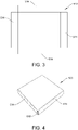
- shield casings which are also known are typically formed from a single piece of flat conductive material 512, typically metal, which is stamped, cut, or etched with four edge portions 514 bent upwards to a position perpendicular to the main surface to form sidewalls of shield casing 520 structure such as that shown in figure 4 (note that the shield casings 510 and 520 have the same functionality but have been assigned different reference numeral because of their different appearance).
- gaps 516 can exist at the corners of the casing between each adjacent sidewall which can reduce the Electromagnetic Compatibility (EMC) performance of the shield casing.
- EMC Electromagnetic Compatibility
- US 9055666 B2 relates to clip terminal soldered to and mounted on a circuit board, the terminal including a connection part bent at an angle corresponding to that of a corner of a case and at least a pair of clips connected to each other by the connection part.
- the connection part and the clips are integrated with each other.
- the connection part has a width less than or equal to that of a solder pattern of the circuit board on which the clip terminal is soldered.
- a lower end of the corner of a sidewall of the case is fitted into the clips.
- support walls are provided that uprightly protrude along an outer edge. Each support wall may have a height less that of plastic pieces that form the pair of clips.
- JP2013211294A relates to a clip terminal that includes a guide part formed along an outer contour of a corner of a shield case, and a terminal side engagement part which is formed at a part of the guide part for click fitting.
- a case side engagement part is formed which is engaged with the terminal side engagement part for click fitting, and the side surface of the shield case is click-fitted to and held on a plurality of clip terminals fixed to a circuit board.
- US 7876579 relates to an anti-electromagnetic interference (anti-EMI) corner shield unit for a shielding device.
- the shielding device is designed for fastening to a printed circuit board and includes an upper lid and a frame, and the frame includes a plurality of sequentially connected side walls with a gap left at each joint of two adjacent side walls.
- the anti-EMI corner shield unit includes an L-shaped shield plate having a first and a second shield plate for mounting to an inner side of each corner of the frame formed at the joint of any two adjacent side walls, so as to completely shield the gap left at the joint; and a clip provided at a lower edge of each of the first and the second shield plate for receiving and firmly clamping on the side wall of the frame.
- US2013148318 A1 relates to a clip terminal soldered to and mounted on a circuit board, and includes a connection part bent at an angle corresponding to that of a corner of a case and at least a pair of clips connected to each other by the connection part.
- the connection part and the clips are integrated with each other.
- the connection part has a width less than or equal to that of a solder pattern of the circuit board on which the clip terminal is soldered. A lower end of the corner of a sidewall of the case is fitted into the clips.
- JP2011198839A relates to a clip terminal, for positioning and holding a shield case, that has a side wall, which is arranged in the proximity of a side face of the shield case from outside and has a side wall with a bent portion formed so as to be a shape bent in an L shape along the side face of the shield case at the corner portion of the shield case.
- US 6051781 relates to a unitary metal clip that is stamped from a flat strip of sheet metal which is bent to provide two pairs of generally V-shaped fingers which extend upwardly from a base and have opposing apexes.
- An L-shaped arm also extends upwardly from the base between the pairs of fingers and has a horizontal pick-up tab that is located at a height above the opposing apexes of the fingers.
- a pneumatic head of an automatic pick and place machine grabs the pick-up tab and removes the clip from a pocket of a supply tape unrolled from a reel.
- the base of the clip is positioned on a solder pad of a PC board before solder re-flow.
- the lower edge of the sidewall of an EMI shield may be pressed down to bend the pick-up tab downwardly and squeeze the sidewall between the apexes of the fingers.
- the present invention provides a clip terminal according to appended claim 1.
- the first outwardly extending portion is at an angle to the second outwardly extending portion.
- the angle may be such that the first outwardly extending portion and the second outwardly extending portion form a substantially perpendicular shape corresponding to that of a corner portion of the casing.
- the shielding part may shield the corner portion of the casing.
- each of the first portion and the second portion comprise a pair of the upstanding clips.
- the shielding part also acts as a guiding member for the casing in that it enables a casing to be fed in diagonal and then in a downward direction such that the casing is aligned to sit in between the upstanding retention clips that are located on the first and second portion.
- the pair of clips are integral with the connector part and the shielding part is integral with the connector part.
- the shielding part projects upwards at an incline and not perpendicular relative to the surface of the connector part, such that the shielding part is bent inwards towards the connector part. Therefore, at least the top part of the shielding part can contact at least part of the casing to be retained by the clip terminal.
- the angle of the incline is such that the shielding part enables a gap in a corner of a casing to be substantially covered to reduce EMI entering the casing.
- the angle could be around 86 degrees relative to the surface of the connector part (which can be considered 94 degrees in the direction of bending) but the invention is not limited to this angle.
- the shielding part comprises a first shielding wall connected to an outer edge of the first outwardly extending portion of the connector part and a second shielding wall connected to the first shielding wall and having a planar surface axially aligned with an outer edge of the second outwardly extending portion of the connector part.
- the first shielding wall has an extension portion at a top end of the wall that forms a surface which can be sufficiently interacted with and picked up by a suction instrument of a conventional clip terminal mounting machine.
- the surface of the extension portion may be substantially parallel to the surface of the connector part.
- the second shielding wall has a top end which can be sufficiently gripped and picked up by a gripping instrument of a conventional clip terminal mounting machine.
- the pair of upstanding retention clips may comprise a first clip attached to an outer edge of the connector part and a second clip attached to an inner edge of the connector part, wherein at a lower portion of the pair of clips, the first clip and second clips converge towards each other, at an upper portion the first and second clips diverge away from each other, and the first and second clip are closest at a middle portion between the lower and upper portions.
- the present invention provides a clip terminal according to appended claim 9.
- the first outwardly extending portion is at an angle to the second outwardly extending portion.
- the angle may be such that the first outwardly extending portion and the second outwardly extending portion form a substantially perpendicular shape corresponding to that of a corner portion of the casing.
- the shielding part may shield a corner portion of the casing.
- each of the first portion and the second portion comprise a pair of the upstanding clips.
- the shielding part also acts as a guiding member for the casing in that it enables a casing to be fed in diagonal and then in a downward direction such that the casing is aligned to sit in between the upstanding retention clips that are located on the first and second portion.
- the pair of clips are integral with the connector part and the shielding part is integral with the connector part.
- the shielding part projects upwards at an incline and not perpendicular relative to the surface of the connector part, such that the shielding part is bent inwards towards the connector part.
- the angle of the incline is such that the shielding part enables a gap in a corner of a casing to be substantially covered to reduce EMI entering the casing.
- the angle could be around 86 degrees relative to the surface of the connector part but the invention is not limited to this angle.
- the pair of clips can be positioned on the first and / or second outwardly extending portions and have a first height relative to a surface of the connector part, and the shielding part has a second height relative to the surface of the connector part, wherein the second height is greater than the first height.
- the pair of upstanding retention clips may comprise a first clip attached to an outer edge of the connector part and a second clip attached to an inner edge of the connector part, wherein at a lower portion of the pair of clips, the first clip and second clips converge towards each other, at an upper portion the first and second clips diverge away from each other, and the first and second clip are closest at a middle portion between the lower and upper portions.
- the present invention provides a method for retaining a casing relative to a circuit board, according to appended claim 11.
- the present invention provides a method for manufacturing a clip terminal such as the clip terminal of the first aspect or second aspect, according to appended claim 12.
- a clip terminal is used to retain a shield casing (also known as a shield can) on a PCB for EMC protection.
- a clip terminal comprises shielding means to reduce a gap that may exist in one or more corners of a shield casing after the casing has been formed, for example, from a piece of stamped material.
- the clip terminal may also be formed automatically using manufacturing machinery and constructed such that it can be automatically picked and placed from a first location, for example, a tape and reel packaging, to a second location, for example, the PCB where it is to be fixed.
- the shielding means to reduce the gap is slightly inclined so that there is contact between at least a portion of the shielding means, for example, the top portion, and the shield casing.
- a clip terminal 100 according to a first embodiment of the invention will now be described with reference to Figures 4 to 11 .
- the clip terminal 100 comprises a base connector part 102 having first outwardly extending portion 104 and a second outwardly extending portion 106.
- the first outwardly extending portion 104 is at an angle to the second outwardly extending portion. The angle is such that the first outwardly extending portion and the second outwardly extending portion form a substantially perpendicular shape corresponding to that of a corner portion of a typical shield casing 520 such as that shown in figure 9 .
- the first outwardly extending portion 104 is horizontal and the second outwardly extending portion 106 is vertical thus corresponding to a corner portion of the shield casing 520.
- the angle is therefore ninety degrees but this could vary depending on the type of shield casing to be used with the clip terminal or where the clip terminal is intended to be placed relative to the casing. In some embodiments (not shown), the angle may be 180 degrees such that the first outwardly extending portion is axially aligned with the second outwardly extending portion more similar to the clip terminal arrangement shown in figure 1 .
- the clip terminal 100 further comprises one or more retention clips to provide a lateral spring force and grip side wall portions 514a, 514b (see figure 9 ) of the shield casing 520.
- a first pair 108 and a second pair 110 of retention clips are provided on the clip terminal, however, it will be appreciated to those skilled in the art with the benefit of this disclosure that any number of retention clips can be provided to grip or contact a part of a side wall of the casing 520.
- the first pair of retention clips 108 have first and second generally upstanding clip elements 112, 114 that are resilient spring portions connected to the first outwardly extending portion 104 of the connector part 102.
- the first clip element 112 is connected to an outer edge of the first outwardly extending portion 104.
- the second clip element 114 is located on an opposite side of first outwardly extending portion 104 and connected to an inner edge of the first outwardly extending portion 104.
- the first clip element 112 and second clip element 114 converge towards each other after an initial divergence adjacent the base of the connector part 102.
- the first clip element 112 and second clip element 114 diverge away from each other, and the first clip element 112 and second clip element 114 are closest at a middle portion between the lower and upper portions.
- the gripping of the side wall of the shield casing 520 can take place at the middle portion.
- the second pair of retention clips 110 have first and second generally upstanding clip elements 116, 118 that are resilient spring portions but are connected to the second outwardly extending portion 106 of the connector part 102.
- the first clip element 116 is connected to an outer edge of the second outwardly extending portion 106.
- the second clip element 118 is located on an opposite side of second outwardly extending portion 106 and connected to an inner edge of the second outwardly extending portion 106.
- the first clip element 116 and second clip element 118 converge towards each other after an initial divergence adjacent the base of the connector part 102.
- the first clip element 116 and second clip element 118 diverge away from each other, and the first clip element 116 and second clip element 118 are closest at a middle portion between the lower and upper portions.
- the gripping of the side wall of the shield casing 520 can take place at the middle portion.
- the first and second pair of retention clips 108, 110 are integral with the connection part 102 and may be formed by bending the clips upwards from the same material as the base connector part 102 into the desired shape suitable for gripping.
- gripping means may be provided instead of the specific retention clip arrangement described and may consist of any other form of resilient elements suitable for providing the required lateral spring force.
- a shielding part 130 is provided on the clip terminal.
- the shielding part 130 is located on an outer edge of the connector part for shielding a portion of the casing where there may be a gap in a wall of the casing 520.
- the shielding part 130 projects generally upwards substantially transversely relative to a planar surface of the base connector part 102.
- the shielding part 130 is integral with the connector part. It will be appreciated that the shielding part may not be integral although there are advantages to having it integral with the connector (and retention clips) and formed from the same material as the base connector part 102.
- the shielding part 130 comprises a first shielding wall 132 connected to an outer edge of the first outwardly extending portion 104 of the connector part 102 and a second shielding wall 134 that is connected to the first shielding wall 132 substantially along one longitudinal edge 132a of the first shielding wall 132 such that the second shielding wall is considered to be bent or folded along the longitudinal edge 132a towards an outer edge of the second outwardly extending portion 106 up to when it is aligned with the outer edge.
- the second shielding wall 134 is bent until it forms about a ninety degree angle with the first shielding portion 132. With this construction there may be a small gap 135 between the bottom of the second shielding wall and the outer edge of the second outwardly extending portion 106.
- the second shielding wall is connected to an outer edge of the second outwardly extending portion of the connector part.
- the shielding part 130 and particularly the first shielding wall 132 projects transversely upwards at an incline and not perpendicular relative to the surface of the connector part, such that the shielding part 130 is bent inwards towards the connector part 102. Therefore, at least the top part of the shielding part 130 can contact at least part of the corner of the shield casing 520 and to provide better shielding and retention.
- the angle of the incline is such that the shielding part enables a gap in a corner of a casing to be substantially covered to reduce EMI entering the casing.
- the angle is acute and around 86 degrees relative to the surface of the connector part 102 however the angle can vary and is not limited to 86 degrees. Looking at the angle relative to the outside of the first shielding wall and the axis of the second outwardly extending portion 106, the angle can be considered to be 94 degrees (as shown in figure 9 ).
- the first shielding wall 132 has an extension portion 136 at a top end of the wall 132 that forms a surface which can be sufficiently interacted with and picked up by a suction instrument of a conventional clip terminal mounting machine (not shown).
- the surface of the extension portion 136 may be substantially parallel to the planar surface of the connector part 102. However, it will be appreciated that such an arrangement is one example and other orientations are possible to provide a surface that enables interaction with a suction instrument.
- the second shielding wall has a top end 138 which can be sufficiently gripped and picked up by a gripping instrument of a conventional clip terminal mounting machine and therefore may not have an extension portion.
- the clip terminal can therefore be easily and automatically transported from a first location, which can be a tape and reel packaging, to a second location, which can be a PCB where it is to be fixed.
- the shielding part 130 has a height Hs greater than the heights H C of the retention clips 108, 110. This can allow easy pick and place of the clip terminal 100 in particular by having a higher point for a pick and place instrument on the top of the shielding part compared to the retention clips which will also be more difficult to pick and place due to their shape.
- the height of the first shielding wall 132 is preferably the same as the second shielding wall 134, however, in other embodiments they may be different without losing the functionality of providing extra shielding and allowing easy automatic pick and placement.
- the shield casing 520 (shown in figure 10 and 11 ) is known and in this embodiment is a conventional hollow cuboid with at least one open face so as to allow it to shield an electrical circuit on the PCB. It will be appreciated that other shield can geometries may be used with the present embodiment, for instance a hollow cube, a hollow triangular cuboid or a hollow dome shaped component could also be used, each having at least one open face so as to allow it to shield an electrical circuit on the PCB.
- the shield casing / can 520 is made from an electrically conductive material so as to protect the shielded circuit from electromagnetic interference (EMI).
- EMI electromagnetic interference
- the can has the ability to attenuate EMI and will contribute to protecting or shielding the circuit contained within it from receiving electromagnetic waves originating from outside the can (and also attenuate electromagnetic waves originating inside the can from exiting).
- the shielding part 130 of the clip terminal 100 acts as a guiding member for the casing 520 in that it enables a casing 520 to be fed in diagonal and then in a downward direction such that the casing 520 is aligned to sit in between the upstanding retention clips 108, 110 that are located on the first and second portion 104, 106.
- the shield casing 520 may be retained to a surface such as a PCB surface using the clip terminal 100 provided in this application and shield casing 520 in combination with the clip terminal 100 to be secured to the surface such as the PCB surface may not be a shield against EMI, but a cover to prevent ingress of dust or water.
- the PCB 530 comprises and is provided with electrical circuitry or some other electronic component (not shown) that requires shielding such as shielding from EMI.
- At least one clip terminal 100 but preferably a plurality of clip terminals are positioned proximal to the electrical circuitry on the PCB, such that when the casing 520 is received in the terminals 100 the casing will shield the electrical circuitry but in particular the corners of the casing 520 to prevent leakage of EMI. Therefore, the clip terminals 100 are located in a positions that are aligned with corresponding corners (not necessarily all corners) of the casing 520.
- the casing 520 is received in the clip terminal 100 to shield the electrical circuitry by positioning the casing 520 so as to abut the clip terminal 100 and in particular so as to abut the base of the clip terminal in order for the casing to be retained.
- the shielding part 130 may abut the corner of the casing 520.
- the casing 520 can thus be retained relative to the PCB 530 by the clip terminal 100.
- the pair of upstanding retention clips on the clip terminal need not take the particular form shown in figure 5 , and may consist of any other form of resilient elements suitable for providing the required lateral spring force on the internal and external surface of a side wall of a shield casing 520.
- the distance between the first clip elements and second clip elements of each pair of retention clips may vary, but will be such to allow at least the middle portion of the retention clips to contact the internal and external surface of a side wall of a shield casing 520 and the part of the retention clips to provide a retention force on the shield casing 520.
- This clips may be designed such that the distance may be adjusted to accommodate different types of shield casings or requirements of the application of the clip terminal 100.
- the design can be such to allow the retention force to be controlled to provide a high retention force for a permanent retention of the casing 520 or a low retention force for easy removal of the casing 520.
- the retention force can be controlled to provide a high retention force for a permanent retention of the casing 520 or a low retention force for easy removal of the casing 520.
- the first clip elements and second clip elements of each pair of retention clips can be made of any material so long as they are not overly flexible (unable to provide a sufficient biasing force) or overly rigid (immoveable through contact with a wall of a shield casing component).
- each clip element used in the pair to secure a component are shown as substantially the same, it will be appreciated by the skilled person that the clip element could have different styles and need not be identical in appearance.
- only one of the pair of retention clips in combination with the shielding part is provided to retain the shield casing.
- only the second clip elements 114,118 of each pair of clip elements i.e. the elements that are situated internal to the side wall of the shield casing 520
- a shielding part 130 is provided on a modified clip terminal in order to retain the shield casing 520 (for example, one or more clip elements acting on the same or different vertical side walls of the shield casing 520).
- the angle of the shielding part 130 relative to the connector part surface may be chosen to ensure contact with the external surface of the side wall of the casing 520 given that the shielding part 130 will be provided the main force for retaining the shield casing from outside the shield casing 520. It will also be appreciated that the distance between the shielding part 130 and the upstanding clips may vary depending on the forces required.
- the clip terminal could be constructed to be straight or another shape (not shown) without such an angle in which case the terminal is used with a straight edge of a shied casing rather than a corner.
- the terminal can thus be modified for use with different types of shield casings.
- clip terminals in some embodiments may be of a suitable size to be received by a printed circuit board and to receive part of a shield casing / can.
- the length of each the first and second outwardly extending portions is around least 5 cm
- the height of the shielding part is around 5 cm
- the height of the pair of upstanding clips is around 2 cm.
- Embodiments for making a clip terminal from a planar strip material will now be described. It will be appreciated that other methods of manufacturing may be used but the automated methods and apparatus disclosed herein have advantages in manufacturing such a clip terminal as disclosed herein with a complex shape and such advantages would be evident to the skilled person with the benefit of the present disclosure.
- the clip terminal 100 in one embodiment can be formed using a manufacturing apparatus including a stripper mounted overbend former assembly 200 that receives a strip 300 which is a planar material stamped or punched such that bending of one of more parts of the material will form the clip terminal 100.
- a stripper mounted overbend former assembly 200 that receives a strip 300 which is a planar material stamped or punched such that bending of one of more parts of the material will form the clip terminal 100.
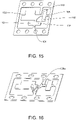
- An example of one portion of the strip 300 used to make one corner clip terminal 100 is shown in figure 15 ; it will be appreciated that the strip 300 is a plurality of these portions arranged adjacent and attached to each other.
- 'Stripper' refers to the stripper plate section of the assembly and this is also referred to as a pressure plate.
- 'Overbend' refers to the forming of a part of the planar material past the required angle. The part will then spring back to the required angle.
- the amount of overbend is determined by the mechanical properties of the material. Both terms will be understood to the skilled person (in the stamping industry). In this embodiment, one method of automatically bending the material is provided.
- the assembly 200 comprises at least clip overbend forming section 210 and shield overbend forming section 250.
- the clip overbend forming section 210 can be a piece of tooling that bends a part of a planar material past 90°.
- the part of the material is usually formed up to 90° by conventional swipe tooling section before entering the clip overbend forming section and the conventional swipe tooling process will not be described in detail as it will be known those in the art.
- a discussion of conventional swipe tooling is provided later (see description related to figures 19-21 ). See figure 16 which shows an example of a clip planar material from a larger strip 300 with a part 108a that is formed up to 90°, substantially perpendicular to the surface of the material.
- overbend tooling such as overbend forming section 210 forms it further so as to overbend to a position as shown by clip 108 (see figure 5 for example), that is past 90° to the surface of overbend forming section 210 (and an acute angle to the base surface of the clip 108).
- 'planar material' refers to the flat, raw material that is punched and formed and is a portion of the strip 300.
- the strip 300 moves in a direction parallel to the longitudinal axis of the assembly 200 (coaxial with the axes X-X and Y-Y shown in figures 13 and 14 respectively).
- the clip overbend forming section 210 is attached to a stripper block 200a which itself is attached to a punch block 200b.
- the clip overbend forming section comprises a plurality of formers 212, preferably two arranged opposite each other along the axis X-X, that when open, will be positioned either side of a clip 108 of clip terminal 100.
- the formers are movable in directions A and B - that is, in a direction parallel to the longitudinal axis of the assembly 200 - and will be driven together by actuators 214 from punch block 200b.
- the actuators 214 are mounted in the punch block 200b and pass through the stripper block 200a.
- the actuators 214 are movable in directions C and D - that is, in a direction substantially perpendicular to the longitudinal axis of the assembly 200 and the direction of movement of the strip 300 through the assembly 200.
- the formers 212 will open by means of two springs 218 that are in contact with the formers 212.
- Stripper block 200a will lift taking the formers 212 with it, and this will allow the strip 300 to feed and the next section of the strip 300 that requires overbending to enter the overbend forming section 210.
- the formers 212 have replaceable inserts 220 which simplify adjustment and servicing.
- the inserts 220 are the tooling parts, which make contact with the part of the planar clip material of the strip 300 to be overbent and in particular have a surface 220a on one side that is angled such that moving opposing surfaces 220a towards each other will contact the outer surfaces of clip elements 112, 114 and overbend these portions to arrive at the configuration, for example, shown in figure 5 .
- the clip 110 that is formed from bending clip elements 116 and 118 can be formed using a conventional swipe tooling and overbend tooling method and will be described later but would be understood by the skilled person and can be incorporated into the assembly 200.
- the central axis of the clip 110 coincides with the axis of movement of the strip through the assembly 200 not requiring the same configuration as the clip overbend section 210 whereas the central axis of the clip 108 is transverse or perpendicular to the axis of movement X of the strip through the assembly 200.
- the shield overbend forming section 250 similarly to the clip overbend forming section can be a piece of tooling that bends a part of a planar material past 90°, that is, past 90° to the surface of shield overbend forming section 210 (and an acute angle to the base surface of the shielding part 130)The part of the material is usually formed up to 90° by conventional swipe tooling before entering the shield overbend forming section and the conventional swipe tooling process will not be described in detail as it will be known those in the art but an example is described later.
- the section 250 comprises a former 252, preferably an inverted U-shaped single block, that when open (i.e.
- the home position of the overbend tooling assembly before it is driven forward will be positioned to the rear of the shielding part 130 (rear when following the direction of travel of the strip 300). It will then be driven forward under the extension portion 136 of the clip terminal 100 which is used as a pick and place tab, by an actuator 254 from the punch block 200b.
- the actuator is movable in direction E - that is, in a direction substantially perpendicular to the longitudinal axis of the assembly 200 and the direction of movement of the strip 300 through the assembly 200.
- the former 252 will open by means of one or more springs, preferably two springs (not shown but housed in former 252 and located either side of insert 260).
- the stripper block 200a will lift taking the former 252 with it, and this will allow the strip 300 to feed.
- the former 252 has the replaceable insert 260 which simplifies adjustment and servicing.
- the inserts 260 are the tooling parts, which make contact with the part of the clip material to be overbent.
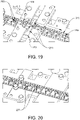
- FIG. 19 shows an example of swipe tooling section 265 where a pair of appropriate formers 266 move up from below the strip and interact with the strip to form the second pair of clips upwards to 90°. This can be achieved by pushing the clip elements 116, 118 upwards from a flat position to the 90° position relative to the strip 300 as the strip moves along the direction X.
- a similar process and machinery although not shown is used for the first pair of clips before the first pair of clips at 90° configuration enter the clip overbend forming section 210.
- Conventional overbend tooling section 270 with a pair of formers 271 is used to overbend the second pair of clips past 90° by applying a force from sides of the first and second clip elements 116, 118 to form the second pair of clips 110.
- the shielding part 130 of the planar strip material is usually formed up to 90° by conventional swipe tooling section 275 before entering the shield overbend forming section 250.
- An appropriate former 276 in the form of a member that has sufficient strength to move the strip when it interacts with it moves up from below the strip and interacts with the strip to form a bend in the portion of the strip material that corresponds to the second shielding wall 134 inwards towards the first shielding wall 132 (see right side of figure 19 ).
- swipe tooling section 277 employing conventional swipe tooling, includes a first part that is used to bend the portion of the strip material that corresponds first shielding wall 132 upwards to 90°.
- the swipe tooling section 277 then has a second part adjacent the first part that bends the portion of the strip material that corresponds extension portion 136 outwards to form the lip of the extension portion. It will be appreciated the order of the conventional strip forming and overbend forming can differ and is not limited to the order described in relation to figures 19 and 20 .
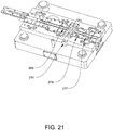
- the swipe tool section 265, overbend tooling section 270 and swipe tool section 275 are positioned after the clip overbend forming section 210 and before the shield overbend forming section 250 in the process path of the manufacturing apparatus. See figure 21 to show Z the example of where the swipe tooling and conventional overbend is located in a die section of the manufacture apparatus.
- the die section of figure 21 is typically a base section for the manufacturing apparatus and is located below the overbend forming assembly 200 shown in figure 12 . Parts of the overbend forming assembly 200 can interact with the planar strip material from above whilst parts of the die section can interact with the planar strip material from below.
- the overbend forming assembly can comprise members 216 (see figure 12 ) extending downwards perpendicular to the plane of the directional path of the strip material and that interact with the strip material from above to hold parts of the strip material in place whilst a part of the die section acts on the strip material (for example, when bending is to take place).
- members 216 see figure 12
- the overbend forming assembly can comprise members 216 (see figure 12 ) extending downwards perpendicular to the plane of the directional path of the strip material and that interact with the strip material from above to hold parts of the strip material in place whilst a part of the die section acts on the strip material (for example, when bending is to take place).
- alternative stripper mounted formers and actuators to those shown in figures 12-14 , and 17-18 may be provided in the assembly 200, as shown in figures 21 and 22 .
- two overbend formers 282a, 282b would be mounted to the stripper block 200a of figure 12 for example instead of formers 212 (see fig. 12-13 ) and are pivotable and rotational about a pivot hole or axis 283 through the formers 282a, 282b which may include an axle (not shown) or other fixed rod member that passes through both former 282a, 282b.
- the formers 282a, 282b are pivotable around the axle when a force is applied to the formers 282a, 282b from above through respective actuators 284a, 284b or some other members that are attached to the punch block 200b and move down in a direction G (that is, perpendicular to the direction of movement of the strip 300) with the punch block 200b.
- the actuators 284a, 284b interact with respective extension portion 285a, 285b of the formers 282a, 282b which cause rotational motion of the formers about the axle.
- the formers 282a, 282b also have foot portions which contact the outer surfaces of clip elements 112, 114 that are in a 90° configuration and overbend these portions to arrive at the configuration, for example, shown in figure 5
- a spring (not shown) that is located on the underside of the former would rotate the former away from the clip 108 and this will allow the strip 300 to feed.
- this modification uses rotational movement of the formers rather than lateral movement which is used in the example assembly that is used to perform the method of manufacturing covered by the appended claims, but is itself as a device not covered by the appended claims in figure 13 and 17 .
- a rotatable overbend former 292 would be mounted to the stripper block 200a in the shield overbend forming section 250 instead of formers 252 (see fig. 12 and 14 ) and would work in a similar way to the formers described in relation to figure 20 .
- the former 292 is pivotable about a pivot hole 293 through the former 292 which may include an axle (not shown) or other fixed rod member that passes through both former 292.
- the former 292 is pivotable around the axle when a force is applied to it from above through an actuator 294 or some other member that is attached to the punch block 200b and move down in a direction H (that is, perpendicular to the direction of movement of the strip 300) with the punch block 200b.
- the actuator 294 interacts with extension portion 295 of the formers 292 which causes rotational motion of the former about the axle.
- the formers 292 also has foot portions which contact the outer surface of shielding portion 130 that is in a 90° configuration and overbend this portion to arrive at the configuration, for example, shown in figure 5 .
- a spring (not shown) that is located on the underside of the former would rotate the former away from the shielding part 130 and this will allow the strip 300 to feed.
- this modification uses rotational movement of the formers rather than lateral movement which is used in the example assembly that is used to perform the method of manufacturing covered by the appended claims, but is itself a device that is not covered by the appended claims in figure 14 and 18 .
- the overbend section can be positioned on top of the die section which can form a base for the overbend section of figure 12 .
- a planar strip 300 is provided which is a single planar material having at least one portion such as that shown in figure 15 that forms a corner clip terminal 100.
- the planar strip is created with stamped and / or punched sections that are to be bent and / or cut during the manufacturing process accordingly to form the clip terminal 100.
- the planar strip can be moved along a pathway of the manufacturing apparatus which includes the assembly 200 that comprises at least the clip overbend forming section 210 and the shield overbend forming section 250.
- the pathway is generally parallel to the longitudinal axis of the second outwardly extending part 106 of the planar material that forms the clip terminal 100 (or from another reference point, generally parallel to the central axis of the second pair of clips 110) and generally perpendicular to the longitudinal axis of the first outwardly extending part 104 of the planar material that forms the clip terminal 100 (or from another reference point, generally perpendicular to the central axis of the first pair of clips 108).
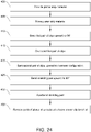
- step 410 the first pair of clips on the first outwardly extending part 104 are bent upwards towards each other to be substantially formed to 90° to the surface of the first outwardly extending part of the strip material in an upstanding configuration 108a (see figure 16 ).
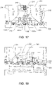
- step 415 the first pair of clips formed in step 410 move to the clip overbend forming section 210 to be overbent as described in one example in relation to apparatus in figures 13 and 17 .
- step 420 the strip portion with the overbent first pair of clips 108 moves to a section such as a conventional swipe tooling section (see figure 19 ) that bends upwards at substantially 90° to the surface the second pair of clips 110 and then overbends to an overbent configuration to a similar extent to the first pair of clips 108 (also see figure 18 showing that the second pair of clips are already formed).
- a section such as a conventional swipe tooling section (see figure 19 ) that bends upwards at substantially 90° to the surface the second pair of clips 110 and then overbends to an overbent configuration to a similar extent to the first pair of clips 108 (also see figure 18 showing that the second pair of clips are already formed).
- the portion of the strip material including the formed first pair of clips 108 and second pair of clips 110 moves to a section where the portions of the strip material that correspond to the shielding part 130 are formed into shape to 90° to the surface of the strip material.
- This can be achieved in a conventional way by bending the portion of the strip material that corresponds second shielding wall 134 inwards towards the first shielding wall 132, bending the portion of the strip material that corresponds first shielding wall 132 upwards, and bending the portion of the strip material that corresponds extension portion 136 outwards to form the lip on the first shielding wall 132.
- the shielding part in this configuration is at up to 90° to the surface of the strip material.
- An example of the process is shown in figure 19 and 20 described above.
- step 430 the portion of strip material formed in step 425 moves to the shield overbend forming section 210 to overbend the shielding part 130 as described in one example in relation to apparatus in figures 14 and 18 .
Landscapes
- Engineering & Computer Science (AREA)
- Microelectronics & Electronic Packaging (AREA)
- Manufacturing & Machinery (AREA)
- Shielding Devices Or Components To Electric Or Magnetic Fields (AREA)
- Manufacturing Of Electrical Connectors (AREA)
- Coupling Device And Connection With Printed Circuit (AREA)
Description
- The invention relates to removably retaining a component to a surface, in particular, to a terminal and method for the retention of a shield casing on a printed circuit board (PCB), and a manufacturing method and apparatus thereof.
- In order to shield electronic components on a PCB in electronic devices against Electromagnetic Interference (EMI) or Radio Frequency Interference (RFI), shielding in the form of an electrically conductive shield casing or box is commonly placed on the PCB so as to cover the electronic components to be shielded. EMI or RFI can be caused by external influences, or by other parts of the electronic circuit itself, such as antennas or power supplies.
- A method of shielding can be achieved when a closed metal can with a free rim at downwardly extending side pieces is soldered to the PCB along the entire free edge of the metal casing. A critical requirement that must be fulfilled in order to achieve good shielding is that the connection between the shield casing free edges and the PCB is well controlled. If any areas of the free edges are not in contact with the PCB creating an electrical contact, the shielding efficiency can be influenced by the largest gap between the shield casing and the PCB. A disadvantage of directly soldering the shield casing to the PCB is in the difficulty of removing the shield casing once it has been attached. Some arrangements include a soldered casing on the PCB, with a removable cap to make up the shield casing. This arrangement provides the permanent fixture of the shield casing, whilst permitting access to the PCB; however the permitted access is limited by the remaining part of the casing that is not part of the cap.
- Soldering is not the only method of mounting a shield casing to a PCB; other methods include the use of shield clips fixed to the PCB, an example of which is shown in
figures 1 and 2 which show aclip terminal 500 that can "pinch" the free edges of atypical shield casing 510, the clip terminal applying a force to two opposite faces of a free edge of the shield casing in order to retain its position. Using shield clips provides the advantage of removably securing the shield casing to a PCB 530. - Referring to
figure 3 , shield casings which are also known are typically formed from a single piece of flatconductive material 512, typically metal, which is stamped, cut, or etched with fouredge portions 514 bent upwards to a position perpendicular to the main surface to form sidewalls ofshield casing 520 structure such as that shown infigure 4 (note that theshield casings gaps 516 can exist at the corners of the casing between each adjacent sidewall which can reduce the Electromagnetic Compatibility (EMC) performance of the shield casing. -
US 9055666 B2 -
JP2013211294A -
US 7876579 relates to an anti-electromagnetic interference (anti-EMI) corner shield unit for a shielding device. The shielding device is designed for fastening to a printed circuit board and includes an upper lid and a frame, and the frame includes a plurality of sequentially connected side walls with a gap left at each joint of two adjacent side walls. The anti-EMI corner shield unit includes an L-shaped shield plate having a first and a second shield plate for mounting to an inner side of each corner of the frame formed at the joint of any two adjacent side walls, so as to completely shield the gap left at the joint; and a clip provided at a lower edge of each of the first and the second shield plate for receiving and firmly clamping on the side wall of the frame.US2013148318 A1 relates to a clip terminal soldered to and mounted on a circuit board, and includes a connection part bent at an angle corresponding to that of a corner of a case and at least a pair of clips connected to each other by the connection part. The connection part and the clips are integrated with each other. The connection part has a width less than or equal to that of a solder pattern of the circuit board on which the clip terminal is soldered. A lower end of the corner of a sidewall of the case is fitted into the clips. -
JP2011198839A -
US 6051781 relates to a unitary metal clip that is stamped from a flat strip of sheet metal which is bent to provide two pairs of generally V-shaped fingers which extend upwardly from a base and have opposing apexes. An L-shaped arm also extends upwardly from the base between the pairs of fingers and has a horizontal pick-up tab that is located at a height above the opposing apexes of the fingers. A pneumatic head of an automatic pick and place machine grabs the pick-up tab and removes the clip from a pocket of a supply tape unrolled from a reel. The base of the clip is positioned on a solder pad of a PC board before solder re-flow. The lower edge of the sidewall of an EMI shield may be pressed down to bend the pick-up tab downwardly and squeeze the sidewall between the apexes of the fingers. - There remains a need to provide an improved removable retention of a PCB shield casing, whilst maintaining EMC performance.
- There is also a need for a clip terminal that is versatile and can be used with one or more existing clip mounting techniques such as automatic pick and placement techniques from tape and reel packaging.
- There is also a need to provide an improved manufacturing method and apparatus for such a clip.
- From a first aspect, the present invention provides a clip terminal according to appended claim 1.
- In an embodiment, the first outwardly extending portion is at an angle to the second outwardly extending portion. The angle may be such that the first outwardly extending portion and the second outwardly extending portion form a substantially perpendicular shape corresponding to that of a corner portion of the casing. The shielding part may shield the corner portion of the casing.
- In an embodiment, each of the first portion and the second portion comprise a pair of the upstanding clips. The shielding part also acts as a guiding member for the casing in that it enables a casing to be fed in diagonal and then in a downward direction such that the casing is aligned to sit in between the upstanding retention clips that are located on the first and second portion.
- In an embodiment, the pair of clips are integral with the connector part and the shielding part is integral with the connector part.
- The shielding part projects upwards at an incline and not perpendicular relative to the surface of the connector part, such that the shielding part is bent inwards towards the connector part. Therefore, at least the top part of the shielding part can contact at least part of the casing to be retained by the clip terminal. The angle of the incline is such that the shielding part enables a gap in a corner of a casing to be substantially covered to reduce EMI entering the casing. As an example, the angle could be around 86 degrees relative to the surface of the connector part (which can be considered 94 degrees in the direction of bending) but the invention is not limited to this angle.
- In an embodiment, the shielding part comprises a first shielding wall connected to an outer edge of the first outwardly extending portion of the connector part and a second shielding wall connected to the first shielding wall and having a planar surface axially aligned with an outer edge of the second outwardly extending portion of the connector part.
- The first shielding wall has an extension portion at a top end of the wall that forms a surface which can be sufficiently interacted with and picked up by a suction instrument of a conventional clip terminal mounting machine. The surface of the extension portion may be substantially parallel to the surface of the connector part.
- The second shielding wall has a top end which can be sufficiently gripped and picked up by a gripping instrument of a conventional clip terminal mounting machine.
- The pair of upstanding retention clips may comprise a first clip attached to an outer edge of the connector part and a second clip attached to an inner edge of the connector part, wherein at a lower portion of the pair of clips, the first clip and second clips converge towards each other, at an upper portion the first and second clips diverge away from each other, and the first and second clip are closest at a middle portion between the lower and upper portions.
- From a second aspect, the present invention provides a clip terminal according to appended claim 9.
- In an embodiment, the first outwardly extending portion is at an angle to the second outwardly extending portion. The angle may be such that the first outwardly extending portion and the second outwardly extending portion form a substantially perpendicular shape corresponding to that of a corner portion of the casing. The shielding part may shield a corner portion of the casing.
- In an embodiment, each of the first portion and the second portion comprise a pair of the upstanding clips. The shielding part also acts as a guiding member for the casing in that it enables a casing to be fed in diagonal and then in a downward direction such that the casing is aligned to sit in between the upstanding retention clips that are located on the first and second portion.
- In an embodiment, the pair of clips are integral with the connector part and the shielding part is integral with the connector part.
- The shielding part projects upwards at an incline and not perpendicular relative to the surface of the connector part, such that the shielding part is bent inwards towards the connector part. The angle of the incline is such that the shielding part enables a gap in a corner of a casing to be substantially covered to reduce EMI entering the casing. As an example, the angle could be around 86 degrees relative to the surface of the connector part but the invention is not limited to this angle.
- The pair of clips can be positioned on the first and / or second outwardly extending portions and have a first height relative to a surface of the connector part, and the shielding part has a second height relative to the surface of the connector part, wherein the second height is greater than the first height.
- The pair of upstanding retention clips may comprise a first clip attached to an outer edge of the connector part and a second clip attached to an inner edge of the connector part, wherein at a lower portion of the pair of clips, the first clip and second clips converge towards each other, at an upper portion the first and second clips diverge away from each other, and the first and second clip are closest at a middle portion between the lower and upper portions.
- From a third aspect, the present invention provides a method for retaining a casing relative to a circuit board, according to appended claim 11.
- From a fourth aspect, the present invention provides a method for manufacturing a clip terminal such as the clip terminal of the first aspect or second aspect, according to appended claim 12.
- Embodiments of the present invention are now described, by way of example only, with reference to the accompanying drawings, in which:
-
Figure 1 is a perspective view of a clip terminal arrangement known in the prior art; -
Figure 2 is a view of a shield casing located above a typical PCB including a plurality of the clips terminals offig. 1 ; -
Figure 3 is a top view of a known shield casing flat material before it is formed into a shielding casing; -
Figure 4 is a perspective view of a shield casing formed from the shielding casing flat material offigure 3 ; -
Figure 5 is a perspective view of a clip terminal arrangement according to a first embodiment of the invention; -
Figure 6 is a top view of the clip terminal offigure 5 ; -
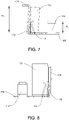
Figure 7 is a view of the clip terminal offigure 5 from a first side; -
Figure 8 is a view of the clip terminal offigure 5 from a second side; -
Figure 9 is a view of the clip terminal offigure 5 from a third side; -
Figure 10 is a perspective view of a clip terminal offigure 5 having received a shield casing such as that offigure 4 ; -
Figure 11 is a closer view of a clip terminal and part of the shield casing offigure 10 ; -
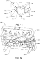
Figure 12 is a bottom perspective view of a stripper mounted overbend former assembly is an example assembly that is itself not covered by the appended claims and that can be used to make a clip terminal of the first embodiment from a strip of planar stamped material, the method of manufacturing being covered by the appended claims, but the assembly itself not. -
Figure 13 is a bottom perspective view showing a clip overbend forming section offigure 12 in more detail; -
Figure 14 is a bottom perspective view showing shield overbend forming section offigure 12 in more detail; -
Figure 15 is a part of a planar strip material that can be used with the stripper mounted overbend former assembly,Figures 12-24 relate to the appended method of manufacturing claims. The assembly is not covered by the appended claims; -
Figure 16 is the material offigure 15 including a feature of the material prior to overbend.Figures 12-24 relate to the appended method of manufacturing claims. The material on its own is not covered by the appended claims; -
Figure 17 is a simplified perspective cross sectional view of the clip overbend forming section offigure 13 taken along the line X-X offigure 13 , the formers being used to interact with a strip of planar stamped material to form a pair of the upstanding clips of the clip terminal, the stripper block offigure 12 being omitted for clarity.Figures 12-24 relate to the appended method of manufacturing claims. The assembly is not covered by the appended claims; -
Figure 18 is a simplified perspective view of the shield overbend forming section offigure 14 taken along the line Y-Y offigure 14 , the formers being used to interact with the strip of planar stamped material to a shielding part of the clip terminal.Figures 12-24 relate to the appended method of manufacturing claims. The assembly is not covered by the appended claims; -
Figure 19 is a top perspective view showing clip and shield forming process section that is located and can occur after the clip forming offigure 17 .Figures 12-24 relate to the appended method of manufacturing claims. The assembly and its individual sections are not covered by the appended claims; -
Figure 20 is a top perspective view showing a continuation of the shield forming section that is located after the clip and initial shield forming process section offigure 18 .Figures 12-24 relate to the appended method of manufacturing claims. The assembly and its individual sections are not covered by the appended claims; -
Figure 21 is a die stamping section of the apparatus that includes the sections offigures 19 and 20 and can be located below theassembly 200 offigure 12 .Figures 12-24 relate to the appended method of manufacturing claims. The assembly and its individual sections are not covered by the appended claims; -
Figure 22 is a simplified perspective view of a clip overbend former and actuator that can be used in the assembly offigure 12 as an alternative to the former and actuator described and shown in relation tofigure 13 and17 .Figures 12-24 relate to the appended method of manufacturing claims. The assembly and the alternative former and actuator are not covered by the appended claims as such; -
Figure 23 is a simplified perspective view of a shield overbend former and actuator that can be used in the assembly offigure 12 as an alternative to the former and actuator described and shown in relation tofigure 14 and18 .Figures 12-24 relate to the appended method of manufacturing claims. The assembly and the former and actuator are not covered by the appended claims as such; -
Figure 24 is a flow diagram of the process of manufacturing using the apparatus offigures 12 and21 . The process of manufacturing is covered by the appended method claims, while the apparatus to do so, is not. - A clip terminal is used to retain a shield casing (also known as a shield can) on a PCB for EMC protection. In some embodiments of the invention, a clip terminal comprises shielding means to reduce a gap that may exist in one or more corners of a shield casing after the casing has been formed, for example, from a piece of stamped material. The clip terminal may also be formed automatically using manufacturing machinery and constructed such that it can be automatically picked and placed from a first location, for example, a tape and reel packaging, to a second location, for example, the PCB where it is to be fixed. In some embodiments, the shielding means to reduce the gap is slightly inclined so that there is contact between at least a portion of the shielding means, for example, the top portion, and the shield casing.
- A
clip terminal 100 according to a first embodiment of the invention will now be described with reference toFigures 4 to 11 . - In the first embodiment, the
clip terminal 100 comprises abase connector part 102 having first outwardly extendingportion 104 and a second outwardly extendingportion 106. In this embodiment, the first outwardly extendingportion 104 is at an angle to the second outwardly extending portion. The angle is such that the first outwardly extending portion and the second outwardly extending portion form a substantially perpendicular shape corresponding to that of a corner portion of atypical shield casing 520 such as that shown infigure 9 . Put another way, the first outwardly extendingportion 104 is horizontal and the second outwardly extendingportion 106 is vertical thus corresponding to a corner portion of theshield casing 520. The angle is therefore ninety degrees but this could vary depending on the type of shield casing to be used with the clip terminal or where the clip terminal is intended to be placed relative to the casing. In some embodiments (not shown), the angle may be 180 degrees such that the first outwardly extending portion is axially aligned with the second outwardly extending portion more similar to the clip terminal arrangement shown infigure 1 . - The
clip terminal 100 further comprises one or more retention clips to provide a lateral spring force and gripside wall portions figure 9 ) of theshield casing 520. In this embodiment, afirst pair 108 and asecond pair 110 of retention clips are provided on the clip terminal, however, it will be appreciated to those skilled in the art with the benefit of this disclosure that any number of retention clips can be provided to grip or contact a part of a side wall of thecasing 520. - The first pair of
retention clips 108 have first and second generallyupstanding clip elements portion 104 of theconnector part 102. Thefirst clip element 112 is connected to an outer edge of the first outwardly extendingportion 104. Thesecond clip element 114 is located on an opposite side of first outwardly extendingportion 104 and connected to an inner edge of the first outwardly extendingportion 104. At a lower portion of the first pair ofclips 108, thefirst clip element 112 andsecond clip element 114 converge towards each other after an initial divergence adjacent the base of theconnector part 102. At an upper portion of the first pair ofclips 108, thefirst clip element 112 andsecond clip element 114 diverge away from each other, and thefirst clip element 112 andsecond clip element 114 are closest at a middle portion between the lower and upper portions. The gripping of the side wall of theshield casing 520 can take place at the middle portion. Similarly to the first pair of retention clips, the second pair ofretention clips 110 have first and second generallyupstanding clip elements portion 106 of theconnector part 102. Thefirst clip element 116 is connected to an outer edge of the second outwardly extendingportion 106. Thesecond clip element 118 is located on an opposite side of second outwardly extendingportion 106 and connected to an inner edge of the second outwardly extendingportion 106. At a lower portion of the second pair ofclips 110, thefirst clip element 116 andsecond clip element 118 converge towards each other after an initial divergence adjacent the base of theconnector part 102. At an upper portion of the second pair ofclips 110, thefirst clip element 116 andsecond clip element 118 diverge away from each other, and thefirst clip element 116 andsecond clip element 118 are closest at a middle portion between the lower and upper portions. The gripping of the side wall of theshield casing 520 can take place at the middle portion. - The first and second pair of
retention clips connection part 102 and may be formed by bending the clips upwards from the same material as thebase connector part 102 into the desired shape suitable for gripping. - It will be appreciated that, in other embodiments, other types of gripping means may be provided instead of the specific retention clip arrangement described and may consist of any other form of resilient elements suitable for providing the required lateral spring force.
- In order to enable more complete shielding and protection of electrical components contained with the
shield casing 520 when positioned in theclip terminal 100, a shieldingpart 130 is provided on the clip terminal. In this embodiment, the shieldingpart 130 is located on an outer edge of the connector part for shielding a portion of the casing where there may be a gap in a wall of thecasing 520. The shieldingpart 130 projects generally upwards substantially transversely relative to a planar surface of thebase connector part 102. The shieldingpart 130 is integral with the connector part. It will be appreciated that the shielding part may not be integral although there are advantages to having it integral with the connector (and retention clips) and formed from the same material as thebase connector part 102. - The shielding
part 130 comprises afirst shielding wall 132 connected to an outer edge of the first outwardly extendingportion 104 of theconnector part 102 and asecond shielding wall 134 that is connected to thefirst shielding wall 132 substantially along onelongitudinal edge 132a of thefirst shielding wall 132 such that the second shielding wall is considered to be bent or folded along thelongitudinal edge 132a towards an outer edge of the second outwardly extendingportion 106 up to when it is aligned with the outer edge. In this embodiment, thesecond shielding wall 134 is bent until it forms about a ninety degree angle with thefirst shielding portion 132. With this construction there may be asmall gap 135 between the bottom of the second shielding wall and the outer edge of the second outwardly extendingportion 106. - In other embodiments (not shown), the second shielding wall is connected to an outer edge of the second outwardly extending portion of the connector part.
- In this embodiment, the shielding
part 130 and particularly thefirst shielding wall 132 projects transversely upwards at an incline and not perpendicular relative to the surface of the connector part, such that the shieldingpart 130 is bent inwards towards theconnector part 102. Therefore, at least the top part of the shieldingpart 130 can contact at least part of the corner of theshield casing 520 and to provide better shielding and retention. The angle of the incline is such that the shielding part enables a gap in a corner of a casing to be substantially covered to reduce EMI entering the casing. In this embodiment, the angle is acute and around 86 degrees relative to the surface of theconnector part 102 however the angle can vary and is not limited to 86 degrees. Looking at the angle relative to the outside of the first shielding wall and the axis of the second outwardly extendingportion 106, the angle can be considered to be 94 degrees (as shown infigure 9 ). - The
first shielding wall 132 has anextension portion 136 at a top end of thewall 132 that forms a surface which can be sufficiently interacted with and picked up by a suction instrument of a conventional clip terminal mounting machine (not shown). The surface of theextension portion 136 may be substantially parallel to the planar surface of theconnector part 102. However, it will be appreciated that such an arrangement is one example and other orientations are possible to provide a surface that enables interaction with a suction instrument. - The second shielding wall has a
top end 138 which can be sufficiently gripped and picked up by a gripping instrument of a conventional clip terminal mounting machine and therefore may not have an extension portion. - The clip terminal can therefore be easily and automatically transported from a first location, which can be a tape and reel packaging, to a second location, which can be a PCB where it is to be fixed.
- As shown in more detail in
figure 7 , in this embodiment, the shieldingpart 130 has a height Hs greater than the heights HC of the retention clips 108, 110. This can allow easy pick and place of theclip terminal 100 in particular by having a higher point for a pick and place instrument on the top of the shielding part compared to the retention clips which will also be more difficult to pick and place due to their shape. The height of thefirst shielding wall 132 is preferably the same as thesecond shielding wall 134, however, in other embodiments they may be different without losing the functionality of providing extra shielding and allowing easy automatic pick and placement. - The shield casing 520 (shown in
figure 10 and11 ) is known and in this embodiment is a conventional hollow cuboid with at least one open face so as to allow it to shield an electrical circuit on the PCB. It will be appreciated that other shield can geometries may be used with the present embodiment, for instance a hollow cube, a hollow triangular cuboid or a hollow dome shaped component could also be used, each having at least one open face so as to allow it to shield an electrical circuit on the PCB. - The shield casing / can 520 is made from an electrically conductive material so as to protect the shielded circuit from electromagnetic interference (EMI). In particular, the can has the ability to attenuate EMI and will contribute to protecting or shielding the circuit contained within it from receiving electromagnetic waves originating from outside the can (and also attenuate electromagnetic waves originating inside the can from exiting). The shielding
part 130 of theclip terminal 100 acts as a guiding member for thecasing 520 in that it enables acasing 520 to be fed in diagonal and then in a downward direction such that thecasing 520 is aligned to sit in between the upstanding retention clips 108, 110 that are located on the first andsecond portion - In some embodiments, the
shield casing 520 may be retained to a surface such as a PCB surface using theclip terminal 100 provided in this application andshield casing 520 in combination with theclip terminal 100 to be secured to the surface such as the PCB surface may not be a shield against EMI, but a cover to prevent ingress of dust or water. - In a method of retaining the
casing 520 relative to thePCB 530, thePCB 530 comprises and is provided with electrical circuitry or some other electronic component (not shown) that requires shielding such as shielding from EMI. At least oneclip terminal 100, but preferably a plurality of clip terminals are positioned proximal to the electrical circuitry on the PCB, such that when thecasing 520 is received in theterminals 100 the casing will shield the electrical circuitry but in particular the corners of thecasing 520 to prevent leakage of EMI. Therefore, theclip terminals 100 are located in a positions that are aligned with corresponding corners (not necessarily all corners) of thecasing 520. Thecasing 520 is received in theclip terminal 100 to shield the electrical circuitry by positioning thecasing 520 so as to abut theclip terminal 100 and in particular so as to abut the base of the clip terminal in order for the casing to be retained. The shieldingpart 130 may abut the corner of thecasing 520. Thecasing 520 can thus be retained relative to thePCB 530 by theclip terminal 100. - It will be appreciated that the pair of upstanding retention clips on the clip terminal need not take the particular form shown in
figure 5 , and may consist of any other form of resilient elements suitable for providing the required lateral spring force on the internal and external surface of a side wall of ashield casing 520. The distance between the first clip elements and second clip elements of each pair of retention clips may vary, but will be such to allow at least the middle portion of the retention clips to contact the internal and external surface of a side wall of ashield casing 520 and the part of the retention clips to provide a retention force on theshield casing 520. This clips may be designed such that the distance may be adjusted to accommodate different types of shield casings or requirements of the application of theclip terminal 100. For example, the design can be such to allow the retention force to be controlled to provide a high retention force for a permanent retention of thecasing 520 or a low retention force for easy removal of thecasing 520. With removal retention of ashield casing 520 to a surface such as a printed circuit board, maintenance or fault finding on the surface can be aided given that the shield casing can be removed. - The first clip elements and second clip elements of each pair of retention clips can be made of any material so long as they are not overly flexible (unable to provide a sufficient biasing force) or overly rigid (immoveable through contact with a wall of a shield casing component). Although each clip element used in the pair to secure a component are shown as substantially the same, it will be appreciated by the skilled person that the clip element could have different styles and need not be identical in appearance.
- It will also be appreciated that in some embodiments (not shown but derivable from the current figures), only one of the pair of retention clips in combination with the shielding part is provided to retain the shield casing. In one embodiment, only the second clip elements 114,118 of each pair of clip elements (i.e. the elements that are situated internal to the side wall of the shield casing 520) and a shielding
part 130 is provided on a modified clip terminal in order to retain the shield casing 520 (for example, one or more clip elements acting on the same or different vertical side walls of the shield casing 520). The angle of the shieldingpart 130 relative to the connector part surface may be chosen to ensure contact with the external surface of the side wall of thecasing 520 given that the shieldingpart 130 will be provided the main force for retaining the shield casing from outside theshield casing 520. It will also be appreciated that the distance between the shieldingpart 130 and the upstanding clips may vary depending on the forces required. - Although an angled clip terminal with substantially a ninety degree corner is described and shown in the figures, it will be appreciated to those skilled in the art with the benefit of the present disclosure that the clip terminal could be constructed to be straight or another shape (not shown) without such an angle in which case the terminal is used with a straight edge of a shied casing rather than a corner. The terminal can thus be modified for use with different types of shield casings.
- It will be appreciated that clip terminals in some embodiments may be of a suitable size to be received by a printed circuit board and to receive part of a shield casing / can. In one embodiment, the length of each the first and second outwardly extending portions is around least 5 cm, the height of the shielding part is around 5 cm and the height of the pair of upstanding clips is around 2 cm. These dimensions are provided by way of example only (the invention not being limited to such dimensions) and to demonstrate the scale of some embodiments of the invention.
- Embodiments for making a clip terminal from a planar strip material will now be described. It will be appreciated that other methods of manufacturing may be used but the automated methods and apparatus disclosed herein have advantages in manufacturing such a clip terminal as disclosed herein with a complex shape and such advantages would be evident to the skilled person with the benefit of the present disclosure.
- Referring to
figures 12 to 18 , theclip terminal 100 in one embodiment can be formed using a manufacturing apparatus including a stripper mounted overbendformer assembly 200 that receives astrip 300 which is a planar material stamped or punched such that bending of one of more parts of the material will form theclip terminal 100. An example of one portion of thestrip 300 used to make onecorner clip terminal 100 is shown infigure 15 ; it will be appreciated that thestrip 300 is a plurality of these portions arranged adjacent and attached to each other. 'Stripper' refers to the stripper plate section of the assembly and this is also referred to as a pressure plate. 'Overbend' refers to the forming of a part of the planar material past the required angle. The part will then spring back to the required angle. The amount of overbend is determined by the mechanical properties of the material. Both terms will be understood to the skilled person (in the stamping industry). In this embodiment, one method of automatically bending the material is provided. Theassembly 200 comprises at least clipoverbend forming section 210 and shieldoverbend forming section 250. - The clip
overbend forming section 210 can be a piece of tooling that bends a part of a planar material past 90°. The part of the material is usually formed up to 90° by conventional swipe tooling section before entering the clip overbend forming section and the conventional swipe tooling process will not be described in detail as it will be known those in the art. A discussion of conventional swipe tooling is provided later (see description related tofigures 19-21 ). Seefigure 16 which shows an example of a clip planar material from alarger strip 300 with apart 108a that is formed up to 90°, substantially perpendicular to the surface of the material. Then overbend tooling such asoverbend forming section 210 forms it further so as to overbend to a position as shown by clip 108 (seefigure 5 for example), that is past 90° to the surface of overbend forming section 210 (and an acute angle to the base surface of the clip 108). As will be understood by the skilled person, 'planar material' refers to the flat, raw material that is punched and formed and is a portion of thestrip 300. Thestrip 300 moves in a direction parallel to the longitudinal axis of the assembly 200 (coaxial with the axes X-X and Y-Y shown infigures 13 and 14 respectively). - The clip
overbend forming section 210 is attached to astripper block 200a which itself is attached to apunch block 200b. The clip overbend forming section comprises a plurality offormers 212, preferably two arranged opposite each other along the axis X-X, that when open, will be positioned either side of aclip 108 ofclip terminal 100. The formers are movable in directions A and B - that is, in a direction parallel to the longitudinal axis of the assembly 200 - and will be driven together byactuators 214 from punch block 200b.Theactuators 214 are mounted in thepunch block 200b and pass through thestripper block 200a. Theactuators 214 are movable in directions C and D - that is, in a direction substantially perpendicular to the longitudinal axis of theassembly 200 and the direction of movement of thestrip 300 through theassembly 200. When theactuators 214 retract with thepunch block 200b, theformers 212 will open by means of twosprings 218 that are in contact with theformers 212.Stripper block 200a will lift taking theformers 212 with it, and this will allow thestrip 300 to feed and the next section of thestrip 300 that requires overbending to enter theoverbend forming section 210. Theformers 212 havereplaceable inserts 220 which simplify adjustment and servicing. Theinserts 220 are the tooling parts, which make contact with the part of the planar clip material of thestrip 300 to be overbent and in particular have asurface 220a on one side that is angled such that moving opposingsurfaces 220a towards each other will contact the outer surfaces ofclip elements figure 5 . It should be noted that theclip 110 that is formed from bendingclip elements assembly 200. For the formation of the bending ofclip 110, the central axis of theclip 110 coincides with the axis of movement of the strip through theassembly 200 not requiring the same configuration as theclip overbend section 210 whereas the central axis of theclip 108 is transverse or perpendicular to the axis of movement X of the strip through theassembly 200. - The shield
overbend forming section 250 similarly to the clip overbend forming section can be a piece of tooling that bends a part of a planar material past 90°, that is, past 90° to the surface of shield overbend forming section 210 (and an acute angle to the base surface of the shielding part 130)The part of the material is usually formed up to 90° by conventional swipe tooling before entering the shield overbend forming section and the conventional swipe tooling process will not be described in detail as it will be known those in the art but an example is described later. Thesection 250 comprises a former 252, preferably an inverted U-shaped single block, that when open (i.e. the home position of the overbend tooling assembly before it is driven forward), will be positioned to the rear of the shielding part 130 (rear when following the direction of travel of the strip 300). It will then be driven forward under theextension portion 136 of theclip terminal 100 which is used as a pick and place tab, by an actuator 254 from thepunch block 200b. The actuator is movable in direction E - that is, in a direction substantially perpendicular to the longitudinal axis of theassembly 200 and the direction of movement of thestrip 300 through theassembly 200. When theactuator 254 retracts with the punch block, the former 252 will open by means of one or more springs, preferably two springs (not shown but housed in former 252 and located either side of insert 260). Thestripper block 200a will lift taking the former 252 with it, and this will allow thestrip 300 to feed. The former 252 has thereplaceable insert 260 which simplifies adjustment and servicing. Theinserts 260 are the tooling parts, which make contact with the part of the clip material to be overbent. - As mentioned above, conventional swipe tooling can be used to form the first pair of
clips 108a and second pair of clips at 90° upstanding to the surface of thestrip material 300.Figure 19 shows an example ofswipe tooling section 265 where a pair of appropriate formers 266 move up from below the strip and interact with the strip to form the second pair of clips upwards to 90°. This can be achieved by pushing theclip elements strip 300 as the strip moves along the direction X. A similar process and machinery although not shown is used for the first pair of clips before the first pair of clips at 90° configuration enter the clipoverbend forming section 210. Conventionaloverbend tooling section 270 with a pair offormers 271 is used to overbend the second pair of clips past 90° by applying a force from sides of the first andsecond clip elements clips 110. - In addition, the shielding
part 130 of the planar strip material is usually formed up to 90° by conventionalswipe tooling section 275 before entering the shieldoverbend forming section 250. An appropriate former 276 in the form of a member that has sufficient strength to move the strip when it interacts with it (for example a solid block but other structures can be appropriate) moves up from below the strip and interacts with the strip to form a bend in the portion of the strip material that corresponds to thesecond shielding wall 134 inwards towards the first shielding wall 132 (see right side offigure 19 ). As shown infigure 20 ,swipe tooling section 277, employing conventional swipe tooling, includes a first part that is used to bend the portion of the strip material that corresponds first shieldingwall 132 upwards to 90°. Theswipe tooling section 277 then has a second part adjacent the first part that bends the portion of the strip material that correspondsextension portion 136 outwards to form the lip of the extension portion. It will be appreciated the order of the conventional strip forming and overbend forming can differ and is not limited to the order described in relation tofigures 19 and 20 . - In this example assembly, that is used to perform the manufacturing method covered by the appended claims, but is itself not covered by the claims, the
swipe tool section 265,overbend tooling section 270 andswipe tool section 275 are positioned after the clipoverbend forming section 210 and before the shieldoverbend forming section 250 in the process path of the manufacturing apparatus. Seefigure 21 to show Z the example of where the swipe tooling and conventional overbend is located in a die section of the manufacture apparatus. The die section offigure 21 is typically a base section for the manufacturing apparatus and is located below theoverbend forming assembly 200 shown infigure 12 . Parts of theoverbend forming assembly 200 can interact with the planar strip material from above whilst parts of the die section can interact with the planar strip material from below. For example, the overbend forming assembly can comprise members 216 (seefigure 12 ) extending downwards perpendicular to the plane of the directional path of the strip material and that interact with the strip material from above to hold parts of the strip material in place whilst a part of the die section acts on the strip material (for example, when bending is to take place). Other arrangements would be conceivable by the skilled person with the benefit of the present disclosure. - In an alternative arrangement, alternative stripper mounted formers and actuators to those shown in
figures 12-14 , and17-18 may be provided in theassembly 200, as shown infigures 21 and22 . - Referring to
figure 22 , in this modification, two overbend formers 282a, 282b would be mounted to thestripper block 200a offigure 12 for example instead of formers 212 (seefig. 12-13 ) and are pivotable and rotational about a pivot hole oraxis 283 through theformers formers formers respective actuators punch block 200b and move down in a direction G (that is, perpendicular to the direction of movement of the strip 300) with thepunch block 200b. Theactuators respective extension portion formers formers clip elements figure 5 When the actuators 284a, 284b retract, a spring (not shown) that is located on the underside of the former would rotate the former away from theclip 108 and this will allow thestrip 300 to feed. As will be apparent to the skilled person with the benefit of the present disclosure, this modification uses rotational movement of the formers rather than lateral movement which is used in the example assembly that is used to perform the method of manufacturing covered by the appended claims, but is itself as a device not covered by the appended claims infigure 13 and17 . - Referring to
figure 23 , in this modification, a rotatable overbend former 292 would be mounted to thestripper block 200a in the shieldoverbend forming section 250 instead of formers 252 (seefig. 12 and14 ) and would work in a similar way to the formers described in relation tofigure 20 . The former 292 is pivotable about apivot hole 293 through the former 292 which may include an axle (not shown) or other fixed rod member that passes through both former 292. The former 292 is pivotable around the axle when a force is applied to it from above through anactuator 294 or some other member that is attached to thepunch block 200b and move down in a direction H (that is, perpendicular to the direction of movement of the strip 300) with thepunch block 200b. Theactuator 294 interacts withextension portion 295 of theformers 292 which causes rotational motion of the former about the axle. Theformers 292 also has foot portions which contact the outer surface of shieldingportion 130 that is in a 90° configuration and overbend this portion to arrive at the configuration, for example, shown infigure 5 . When theactuator 294 retracts, a spring (not shown) that is located on the underside of the former would rotate the former away from the shieldingpart 130 and this will allow thestrip 300 to feed. As will be apparent to the skilled person with the benefit of the present disclosure, this modification uses rotational movement of the formers rather than lateral movement which is used in the example assembly that is used to perform the method of manufacturing covered by the appended claims, but is itself a device that is not covered by the appended claims infigure 14 and18 . - An example of a method of making the
clip terminal 100 using the manufacturing apparatus that may comprise the overbend section shown infigure 12 and the die section shown infigure 21 is now described with reference tofigure 24 . As will be apparent, the overbend section can be positioned on top of the die section which can form a base for the overbend section offigure 12 . Reference will also be made to the features of theclip terminal 100 shown infigures 5-6 , where appropriate, for ease of explanation. - In
step 400, aplanar strip 300 is provided which is a single planar material having at least one portion such as that shown infigure 15 that forms acorner clip terminal 100. The planar strip is created with stamped and / or punched sections that are to be bent and / or cut during the manufacturing process accordingly to form theclip terminal 100. - In
step 405, the planar strip can be moved along a pathway of the manufacturing apparatus which includes theassembly 200 that comprises at least the clipoverbend forming section 210 and the shieldoverbend forming section 250. The pathway is generally parallel to the longitudinal axis of the second outwardly extendingpart 106 of the planar material that forms the clip terminal 100 (or from another reference point, generally parallel to the central axis of the second pair of clips 110) and generally perpendicular to the longitudinal axis of the first outwardly extendingpart 104 of the planar material that forms the clip terminal 100 (or from another reference point, generally perpendicular to the central axis of the first pair of clips 108). - In
step 410, the first pair of clips on the first outwardly extendingpart 104 are bent upwards towards each other to be substantially formed to 90° to the surface of the first outwardly extending part of the strip material in anupstanding configuration 108a (seefigure 16 ). - In
step 415, the first pair of clips formed instep 410 move to the clipoverbend forming section 210 to be overbent as described in one example in relation to apparatus infigures 13 and17 . - In
step 420, the strip portion with the overbent first pair ofclips 108 moves to a section such as a conventional swipe tooling section (seefigure 19 ) that bends upwards at substantially 90° to the surface the second pair ofclips 110 and then overbends to an overbent configuration to a similar extent to the first pair of clips 108 (also seefigure 18 showing that the second pair of clips are already formed). - In
step 425, the portion of the strip material including the formed first pair ofclips 108 and second pair ofclips 110 moves to a section where the portions of the strip material that correspond to the shieldingpart 130 are formed into shape to 90° to the surface of the strip material. This can be achieved in a conventional way by bending the portion of the strip material that corresponds second shieldingwall 134 inwards towards thefirst shielding wall 132, bending the portion of the strip material that corresponds first shieldingwall 132 upwards, and bending the portion of the strip material that correspondsextension portion 136 outwards to form the lip on thefirst shielding wall 132. The shielding part in this configuration is at up to 90° to the surface of the strip material. An example of the process is shown infigure 19 and 20 described above. - In
step 430, the portion of strip material formed instep 425 moves to the shieldoverbend forming section 210 to overbend the shieldingpart 130 as described in one example in relation to apparatus infigures 14 and18 . - The upstanding portions are now formed and the remaining parts of the planar strip of material not required can be removed in
step 435 to leave theclip terminal 100.
Claims (18)
- A clip terminal (100) for fixedly retaining a casing (520), the clip terminal (100) being suitable for being mounted on a circuit board (530), the clip terminal (100) comprising:a connector part (102) having a first outwardly extending portion (104) and a second outwardly extending portion (106);at least one upstanding retention clip (108, 110) for gripping a side wall portion (514) of acasing (520), wherein the upstanding retention clip (108, 110) is positioned on the first or second outwardly extending portions (104, 106) and has a first height relative to a surface of the connector part (102); anda shielding part (130) located on an outer edge of the connector part (102) for shielding a portion of the casing (520), the shielding part (130) projecting upwards relative to the surface of the connector part (102) and having a second height relative to the surface of the connector part (102), wherein the second height is greater than the first height, characterised in that the shielding part (130) projects upwards at an incline relative to the surface of the connector part (102), such that the shielding part (130) is bent inwards towards the connector part (102), and the angle of the incline is such that a gap (516) in a casing (520) is substantially covered to reduce EMI entering the casing (520) or dust or water entering the casing (520).
- The clip terminal (100) of claim 1, wherein the first outwardly extending portion (104) is at an angle to the second outwardly extending portion (106) and wherein the angle is such that the first outwardly extending portion (104) and the second outwardly extending portion (106) form a substantially perpendicular shape corresponding to that of a corner portion of the casing (520), and the shielding part (130) is configured to shield the corner portion of the casing (520).
- The clip terminal (100) of claim 1 or 2, wherein there is at least a pair of upstanding retention clips (108,110) positioned on the first and / or second outwardly extending portions (104, 106).
- The clip terminal (100) of any preceding claim, where the upstanding retention clip (108) or the pair of upstanding retention clips (108, 110) is / are integral with the connector part (102) and / or wherein the shielding part (130) is integral with the connector part (102).
- The clip terminal (100) of any preceding claim, wherein at least the top part of the shielding part (130) is arranged to contact at least part of the casing (520) to be retained by the clip terminal (100).
- The clip terminal (100) of any preceding claim, wherein the shielding part (130) comprises a first shielding wall (132) connected to an outer edge of the first outwardly extending portion (104) of the connector part (102) and a second shielding wall (134) connected to the first shielding wall (132) and optionally wherein the second shielding wall (134) has a planar surface axially aligned with at least a part of an outer edge of the second outwardly extending portion (106) of the connector part (102).
- The clip terminal (100) of any preceding claim wherein the shielding part (130) comprises an extension portion (136) at a top end that forms a surface which can be sufficiently interacted with and picked up by a suction instrument and / or the shielding part (130) has a top end which can be sufficiently gripped and picked up by a gripping instrument.
- The clip terminal (100) of claim 7, wherein the surface of the extension portion (136) is substantially parallel to the surface of the connector part (102).
- A terminal (100) for fixedly retaining a casing (520), the clip terminal (100) being suitable for being mounted on a circuit board (530), the clip terminal (100) comprising:a connector part (102) having a first outwardly extending portion (104) and a second outwardly extending portion (106);at least one upstanding retention clip (108, 110) for gripping a side wall portion (514) of a casing (520), wherein the upstanding retention clip (108, 110) is positioned on the first or second outwardly extending portions (104, 106);a shielding part (130) located on an outer edge of the connector part (102) for shielding a portion of the casing (520), the shielding part (130) projecting upwards relative to the surface of the connector part (102), the shielding part (130) comprising an extension portion (136) at a top end that forms a surface which can be sufficiently interacted with and picked up by a suction instrument, characterised in that the shielding part (130) projects upwards at an incline relative to the surface of the connector part (102), such that the shielding part (130) is bent inwards towards the connector part (102), and the angle of the incline is such that a gap (516) in a casing (520) is substantially covered to reduce EMI entering the casing (520) or dust or water entering the casing (520).
- The clip terminal (100) of claim 9, wherein the shielding part (130) comprises a first shielding wall (132) connected to an outer edge of the first outwardly extending portion (104) of the connector part (102) and a second shielding wall (134) connected to the first shielding wall (132) and optionally wherein the second shielding wall (134) has a planar surface axially aligned with at least a part of an outer edge of the second outwardly extending portion (106) of the connector part (102).
- A method for retaining a casing (520) relative to a circuit board (530) comprising:providing a circuit board (530) with electrical circuitry;providing at least one clip terminal (100) of any preceding claim in a position proximal to the electrical circuitry on the circuit board (530); andreceiving in the clip terminal (100) a casing (520) to shield the electrical circuitry by positioning the casing (520) so as to abut the clip terminal (100) in order to retain the casing (520) in a position relative to the circuit.
- A method of forming a clip terminal (100) of any of the claims 1-10, comprising:forming (400) a planar strip material (300) comprising stamped sections to be formed into at least one upstanding retention clip (108, 110) for gripping a side wall portion (514) of a casing (520), and into at least one shielding part (130);bending upwards a section of the stamped sections corresponding to the at least one upstanding retention clip (108, 110);bending upwards a section of the stamped sections corresponding to the at least one shielding part (130); andremoving (435) parts of the planar strip material (300) to thereby produce a clip terminal (100) comprising at least one upstanding retention clip (108, 110) and at least one shielding part (130), wherein the step of bending the section of the stamped sections corresponding to the shielding part (130) further comprises bending (425) upwards the shielding part (130) to be formed to substantially 90° to the surface of the planar strip material (300), and then overbending (430) the shielding part (130) beyond substantially 90°.
- The method of claim 12 wherein the section corresponding to the at least one Z upstanding retention clip (108, 110) is connected to the first outwardly extending portion (104) in the planar strip material (300), and the step of bending the section of the stamped sections corresponding to the at least one upstanding retention clip (108, 110) further comprises bending (410) upwards the upstanding retention clip (108, 110) to be formed to substantially 90° to the surface of the first outwardly extending portion (104) of the strip material (300), and then overbending (415) the at least one upstanding retention clip (108, 110) beyond substantially 90°.
- The method of claim 12 or 13, wherein the section corresponding to a second upstanding retention clip (110) is connected to the second outwardly extending part (106) in the planar strip material (300).
- A method of claim 12, wherein the step of bending upwards the section of the stamped sections corresponding to the at least one upstanding retention clip (108, 110) comprises:bending a first upstanding retention clip (108)section of a planar strip material (300) to form a first upstanding retention clip (108) having a central axis;moving the formed first upstanding retention clip (108) along a directional path with an axis that is substantially perpendicular to the central axis;overbending the formed first upstanding retention clip (108) through a first overbend mechanism (210) that interacts with the first upstanding retention clip (108) from above and provides a force in a direction that is substantially parallel to the path axis such that upstanding retention clip (108) is bent inwards.
- The method of claim 15, wherein the step of bending upwards the section of the stamped sections corresponding to the at least one shielding part (130) further comprises:bending a shielding section of a planar strip material (300) to form an upstanding shielding part (130), the shielding part (130) having a longitudinal axis that is substantially perpendicular to the surface of the planar strip material (300);moving the formed upstanding shielding part (130) pent along the directional path; and the overbending of the shielding part (130) beyond substantially 90° further comprises:
overbending the formed upstanding shielding part (130) through a second overbend mechanism (250) that interacts with the shielding part (130) from above and provides a force in a direction that is substantially parallel to the path axis such that shielding part (130) is bent inwards. - The method of claims 15 or 16, wherein the method further comprises:bending a second upstanding retention clip (108, 110) section of a planar strip material (300) to form a second upstanding retention clip (108, 110) having a central axis;moving the formed second upstanding retention clip (108, 110) along a directional path with an axis that is substantially parallel to the central axis;overbending the formed second upstanding retention clip (108, 110) through a second overbend mechanism that interacts with the second upstanding retention clip (108, 110) from above and provides a force in a direction that is substantially perpendicular to the path axis such that upstanding retention clip (108, 110) is bent inwards.
- The method of any of claims 15 to 17, wherein the first overbend mechanism comprises at least one former (212) that is movable in a direction substantially parallel to the directional path and / or about a rotational axis and optionally wherein the first overbend mechanism further comprises at least one actuator (214) that drives the formers in the substantially parallel direction.
Applications Claiming Priority (1)
| Application Number | Priority Date | Filing Date | Title |
|---|---|---|---|
| GB1815992.1A GB2577684A (en) | 2018-10-01 | 2018-10-01 | Terminal and method for retaining a component to a surface, and manufacturing method and apparatus |
Publications (3)
| Publication Number | Publication Date |
|---|---|
| EP3634097A2 EP3634097A2 (en) | 2020-04-08 |
| EP3634097A3 EP3634097A3 (en) | 2020-07-22 |
| EP3634097B1 true EP3634097B1 (en) | 2022-10-26 |
Family
ID=68109179
Family Applications (1)
| Application Number | Title | Priority Date | Filing Date |
|---|---|---|---|
| EP19200737.5A Active EP3634097B1 (en) | 2018-10-01 | 2019-10-01 | Terminal and method for retaining a component to a surface, and manufacturing method and apparatus |
Country Status (4)
| Country | Link |
|---|---|
| US (1) | US10869416B2 (en) |
| EP (1) | EP3634097B1 (en) |
| ES (1) | ES2933819T3 (en) |
| GB (1) | GB2577684A (en) |
Families Citing this family (3)
| Publication number | Priority date | Publication date | Assignee | Title |
|---|---|---|---|---|
| WO2023277902A1 (en) * | 2021-06-30 | 2023-01-05 | Hewlett-Packard Development Company, L.P. | Shield clips |
| CN116014517A (en) | 2021-10-21 | 2023-04-25 | 苏州力特奥维斯保险丝有限公司 | Jumper bus bars with PDM case supports |
| US20240389289A1 (en) * | 2023-05-17 | 2024-11-21 | Intel Corporation | Apparatus and system of electromagnetic interference (emi) shielding |
Family Cites Families (13)
| Publication number | Priority date | Publication date | Assignee | Title |
|---|---|---|---|---|
| JPH0710998A (en) * | 1993-06-25 | 1995-01-13 | Asahi Glass Co Ltd | Method for producing hydrophilic porous membrane |
| JPH0710998U (en) | 1993-07-02 | 1995-02-14 | 幸夫 城尾 | Electronic circuit cover with electromagnetic wave blocking function |
| US6051781A (en) | 1997-09-24 | 2000-04-18 | Autosplice, Inc. | Surface mount electromagnetic frequency interference shield clip |
| JP2000196280A (en) * | 1998-12-25 | 2000-07-14 | Autosplice Inc | Surface-mounted clips for electromagnetic frequency interference shielding |
| CN201029127Y (en) * | 2007-03-09 | 2008-02-27 | 富士康(昆山)电脑接插件有限公司 | electrical connector |
| US7876579B1 (en) * | 2009-09-23 | 2011-01-25 | Ezconn Corporation | Anti-electromagnetic interference corner shield unit for a shielding device |
| JP5566142B2 (en) * | 2010-03-17 | 2014-08-06 | オートスプライス株式会社 | Clip terminal |
| US8188381B2 (en) * | 2010-05-06 | 2012-05-29 | Avago Technologies Fiber Ip (Singapore) Pte. Ltd. | Mid-board module retention and EMI cage |
| JP5467469B2 (en) | 2011-01-04 | 2014-04-09 | 山栄化学株式会社 | Method of surface mounting on printed wiring board |
| WO2013085123A1 (en) * | 2011-12-09 | 2013-06-13 | 조인셋 주식회사 | Case fixing clip terminal and emi shielding device using same |
| JP2013211294A (en) * | 2012-03-30 | 2013-10-10 | Auto Splice Kk | Shield case assembly |
| CN105246316B (en) * | 2015-11-11 | 2018-09-14 | 中磊电子(苏州)有限公司 | Shade presss from both sides and communication device |
| CN205546409U (en) * | 2016-02-01 | 2016-08-31 | 富士康(昆山)电脑接插件有限公司 | Shielding is pressed from both sides and shield assembly thereof |
-
2018
- 2018-10-01 GB GB1815992.1A patent/GB2577684A/en not_active Withdrawn
-
2019
- 2019-09-30 US US16/587,526 patent/US10869416B2/en active Active
- 2019-10-01 EP EP19200737.5A patent/EP3634097B1/en active Active
- 2019-10-01 ES ES19200737T patent/ES2933819T3/en active Active
Also Published As
| Publication number | Publication date |
|---|---|
| ES2933819T3 (en) | 2023-02-14 |
| EP3634097A2 (en) | 2020-04-08 |
| US20200107477A1 (en) | 2020-04-02 |
| EP3634097A3 (en) | 2020-07-22 |
| US10869416B2 (en) | 2020-12-15 |
| GB2577684A (en) | 2020-04-08 |
Similar Documents
| Publication | Publication Date | Title |
|---|---|---|
| US9055666B2 (en) | Clip terminal for fixing case and shield apparatus using the same | |
| US10869416B2 (en) | Terminal and method for retaining a component to a surface, and manufacturing method and apparatus | |
| US6051781A (en) | Surface mount electromagnetic frequency interference shield clip | |
| CN109659723B (en) | Electric connector and manufacturing method thereof | |
| CN2548312Y (en) | plug connector | |
| WO2010135540A1 (en) | Board-to-board connector | |
| CN105265033B (en) | Electromagnetic wave shielding structure | |
| US11903177B2 (en) | Board level shield (BLS) frames including pickup members with pickup areas rotatable in place when drawn | |
| EP2415126B1 (en) | Shielded connector with improved positioning of the shield | |
| US9437945B2 (en) | Electrical connector with improved terminal | |
| JP3851526B2 (en) | Earth terminal | |
| CN100521406C (en) | Assembling method for electrical connector | |
| JP2009117773A (en) | Electronic apparatus | |
| JP2000196280A (en) | Surface-mounted clips for electromagnetic frequency interference shielding | |
| JP6020509B2 (en) | Circuit board connection terminal | |
| EP4148915A1 (en) | Electrical connection apparatus, manufacturing method, and computer device | |
| JP2006012886A (en) | Shield structure | |
| KR101268088B1 (en) | Clip for fixing shield case for shielding emi and shield apparatus using the same | |
| KR101151689B1 (en) | Clip for fixing shield case for shielding emi and shield apparatus using the same | |
| KR101500719B1 (en) | Side-mounting type contactor and connection structure thereof | |
| TW202249585A (en) | Surface-mounting shield assembly and surface-mounting one-way positioning member for shield convenient for shield mounting and detachment and preventing operator's error during press-mounting of shield | |
| CN217011623U (en) | Motherboard components and terminal equipment | |
| KR101727994B1 (en) | Side-mounting type contactor and connection structure thereof | |
| KR20140064160A (en) | Fixing clip for pcb and shielding apparatus | |
| CN215683114U (en) | Surface mount shield case assembly and surface mount unidirectional positioning member for shield case |
Legal Events
| Date | Code | Title | Description |
|---|---|---|---|
| PUAI | Public reference made under article 153(3) epc to a published international application that has entered the european phase |
Free format text: ORIGINAL CODE: 0009012 |
|
| STAA | Information on the status of an ep patent application or granted ep patent |
Free format text: STATUS: THE APPLICATION HAS BEEN PUBLISHED |
|
| AK | Designated contracting states |
Kind code of ref document: A2 Designated state(s): AL AT BE BG CH CY CZ DE DK EE ES FI FR GB GR HR HU IE IS IT LI LT LU LV MC MK MT NL NO PL PT RO RS SE SI SK SM TR |
|
| AX | Request for extension of the european patent |
Extension state: BA ME |
|
| PUAL | Search report despatched |
Free format text: ORIGINAL CODE: 0009013 |
|
| AK | Designated contracting states |
Kind code of ref document: A3 Designated state(s): AL AT BE BG CH CY CZ DE DK EE ES FI FR GB GR HR HU IE IS IT LI LT LU LV MC MK MT NL NO PL PT RO RS SE SI SK SM TR |
|
| AX | Request for extension of the european patent |
Extension state: BA ME |
|
| RIC1 | Information provided on ipc code assigned before grant |
Ipc: H05K 9/00 20060101AFI20200617BHEP |
|
| STAA | Information on the status of an ep patent application or granted ep patent |
Free format text: STATUS: REQUEST FOR EXAMINATION WAS MADE |
|
| 17P | Request for examination filed |
Effective date: 20200909 |
|
| RBV | Designated contracting states (corrected) |
Designated state(s): AL AT BE BG CH CY CZ DE DK EE ES FI FR GB GR HR HU IE IS IT LI LT LU LV MC MK MT NL NO PL PT RO RS SE SI SK SM TR |
|
| GRAP | Despatch of communication of intention to grant a patent |
Free format text: ORIGINAL CODE: EPIDOSNIGR1 |
|
| STAA | Information on the status of an ep patent application or granted ep patent |
Free format text: STATUS: GRANT OF PATENT IS INTENDED |
|
| INTG | Intention to grant announced |
Effective date: 20220520 |
|
| GRAS | Grant fee paid |
Free format text: ORIGINAL CODE: EPIDOSNIGR3 |
|
| GRAA | (expected) grant |
Free format text: ORIGINAL CODE: 0009210 |
|
| STAA | Information on the status of an ep patent application or granted ep patent |
Free format text: STATUS: THE PATENT HAS BEEN GRANTED |
|
| AK | Designated contracting states |
Kind code of ref document: B1 Designated state(s): AL AT BE BG CH CY CZ DE DK EE ES FI FR GB GR HR HU IE IS IT LI LT LU LV MC MK MT NL NO PL PT RO RS SE SI SK SM TR |
|
| REG | Reference to a national code |
Ref country code: GB Ref legal event code: FG4D |
|
| REG | Reference to a national code |
Ref country code: CH Ref legal event code: EP |
|
| REG | Reference to a national code |
Ref country code: DE Ref legal event code: R096 Ref document number: 602019021030 Country of ref document: DE |
|
| REG | Reference to a national code |
Ref country code: AT Ref legal event code: REF Ref document number: 1528055 Country of ref document: AT Kind code of ref document: T Effective date: 20221115 |
|
| REG | Reference to a national code |
Ref country code: IE Ref legal event code: FG4D |
|
| REG | Reference to a national code |
Ref country code: SE Ref legal event code: TRGR |
|
| REG | Reference to a national code |
Ref country code: LT Ref legal event code: MG9D |
|
| REG | Reference to a national code |
Ref country code: ES Ref legal event code: FG2A Ref document number: 2933819 Country of ref document: ES Kind code of ref document: T3 Effective date: 20230214 |
|
| REG | Reference to a national code |
Ref country code: NL Ref legal event code: MP Effective date: 20221026 |
|
| REG | Reference to a national code |
Ref country code: AT Ref legal event code: MK05 Ref document number: 1528055 Country of ref document: AT Kind code of ref document: T Effective date: 20221026 |
|
| PG25 | Lapsed in a contracting state [announced via postgrant information from national office to epo] |
Ref country code: NL Free format text: LAPSE BECAUSE OF FAILURE TO SUBMIT A TRANSLATION OF THE DESCRIPTION OR TO PAY THE FEE WITHIN THE PRESCRIBED TIME-LIMIT Effective date: 20221026 |
|
| PG25 | Lapsed in a contracting state [announced via postgrant information from national office to epo] |
Ref country code: PT Free format text: LAPSE BECAUSE OF FAILURE TO SUBMIT A TRANSLATION OF THE DESCRIPTION OR TO PAY THE FEE WITHIN THE PRESCRIBED TIME-LIMIT Effective date: 20230227 Ref country code: NO Free format text: LAPSE BECAUSE OF FAILURE TO SUBMIT A TRANSLATION OF THE DESCRIPTION OR TO PAY THE FEE WITHIN THE PRESCRIBED TIME-LIMIT Effective date: 20230126 Ref country code: LT Free format text: LAPSE BECAUSE OF FAILURE TO SUBMIT A TRANSLATION OF THE DESCRIPTION OR TO PAY THE FEE WITHIN THE PRESCRIBED TIME-LIMIT Effective date: 20221026 Ref country code: FI Free format text: LAPSE BECAUSE OF FAILURE TO SUBMIT A TRANSLATION OF THE DESCRIPTION OR TO PAY THE FEE WITHIN THE PRESCRIBED TIME-LIMIT Effective date: 20221026 Ref country code: AT Free format text: LAPSE BECAUSE OF FAILURE TO SUBMIT A TRANSLATION OF THE DESCRIPTION OR TO PAY THE FEE WITHIN THE PRESCRIBED TIME-LIMIT Effective date: 20221026 |
|
| PG25 | Lapsed in a contracting state [announced via postgrant information from national office to epo] |
Ref country code: RS Free format text: LAPSE BECAUSE OF FAILURE TO SUBMIT A TRANSLATION OF THE DESCRIPTION OR TO PAY THE FEE WITHIN THE PRESCRIBED TIME-LIMIT Effective date: 20221026 Ref country code: PL Free format text: LAPSE BECAUSE OF FAILURE TO SUBMIT A TRANSLATION OF THE DESCRIPTION OR TO PAY THE FEE WITHIN THE PRESCRIBED TIME-LIMIT Effective date: 20221026 Ref country code: LV Free format text: LAPSE BECAUSE OF FAILURE TO SUBMIT A TRANSLATION OF THE DESCRIPTION OR TO PAY THE FEE WITHIN THE PRESCRIBED TIME-LIMIT Effective date: 20221026 Ref country code: IS Free format text: LAPSE BECAUSE OF FAILURE TO SUBMIT A TRANSLATION OF THE DESCRIPTION OR TO PAY THE FEE WITHIN THE PRESCRIBED TIME-LIMIT Effective date: 20230226 Ref country code: HR Free format text: LAPSE BECAUSE OF FAILURE TO SUBMIT A TRANSLATION OF THE DESCRIPTION OR TO PAY THE FEE WITHIN THE PRESCRIBED TIME-LIMIT Effective date: 20221026 Ref country code: GR Free format text: LAPSE BECAUSE OF FAILURE TO SUBMIT A TRANSLATION OF THE DESCRIPTION OR TO PAY THE FEE WITHIN THE PRESCRIBED TIME-LIMIT Effective date: 20230127 |
|
| REG | Reference to a national code |
Ref country code: DE Ref legal event code: R097 Ref document number: 602019021030 Country of ref document: DE |
|
| PG25 | Lapsed in a contracting state [announced via postgrant information from national office to epo] |
Ref country code: SM Free format text: LAPSE BECAUSE OF FAILURE TO SUBMIT A TRANSLATION OF THE DESCRIPTION OR TO PAY THE FEE WITHIN THE PRESCRIBED TIME-LIMIT Effective date: 20221026 Ref country code: RO Free format text: LAPSE BECAUSE OF FAILURE TO SUBMIT A TRANSLATION OF THE DESCRIPTION OR TO PAY THE FEE WITHIN THE PRESCRIBED TIME-LIMIT Effective date: 20221026 Ref country code: EE Free format text: LAPSE BECAUSE OF FAILURE TO SUBMIT A TRANSLATION OF THE DESCRIPTION OR TO PAY THE FEE WITHIN THE PRESCRIBED TIME-LIMIT Effective date: 20221026 Ref country code: DK Free format text: LAPSE BECAUSE OF FAILURE TO SUBMIT A TRANSLATION OF THE DESCRIPTION OR TO PAY THE FEE WITHIN THE PRESCRIBED TIME-LIMIT Effective date: 20221026 Ref country code: CZ Free format text: LAPSE BECAUSE OF FAILURE TO SUBMIT A TRANSLATION OF THE DESCRIPTION OR TO PAY THE FEE WITHIN THE PRESCRIBED TIME-LIMIT Effective date: 20221026 |
|
| PG25 | Lapsed in a contracting state [announced via postgrant information from national office to epo] |
Ref country code: SK Free format text: LAPSE BECAUSE OF FAILURE TO SUBMIT A TRANSLATION OF THE DESCRIPTION OR TO PAY THE FEE WITHIN THE PRESCRIBED TIME-LIMIT Effective date: 20221026 Ref country code: AL Free format text: LAPSE BECAUSE OF FAILURE TO SUBMIT A TRANSLATION OF THE DESCRIPTION OR TO PAY THE FEE WITHIN THE PRESCRIBED TIME-LIMIT Effective date: 20221026 |
|
| PLBE | No opposition filed within time limit |
Free format text: ORIGINAL CODE: 0009261 |
|
| STAA | Information on the status of an ep patent application or granted ep patent |
Free format text: STATUS: NO OPPOSITION FILED WITHIN TIME LIMIT |
|
| 26N | No opposition filed |
Effective date: 20230727 |
|
| PG25 | Lapsed in a contracting state [announced via postgrant information from national office to epo] |
Ref country code: SI Free format text: LAPSE BECAUSE OF FAILURE TO SUBMIT A TRANSLATION OF THE DESCRIPTION OR TO PAY THE FEE WITHIN THE PRESCRIBED TIME-LIMIT Effective date: 20221026 |
|
| PG25 | Lapsed in a contracting state [announced via postgrant information from national office to epo] |
Ref country code: MC Free format text: LAPSE BECAUSE OF FAILURE TO SUBMIT A TRANSLATION OF THE DESCRIPTION OR TO PAY THE FEE WITHIN THE PRESCRIBED TIME-LIMIT Effective date: 20221026 |
|
| REG | Reference to a national code |
Ref country code: BE Ref legal event code: MM Effective date: 20231031 |
|
| PG25 | Lapsed in a contracting state [announced via postgrant information from national office to epo] |
Ref country code: LU Free format text: LAPSE BECAUSE OF NON-PAYMENT OF DUE FEES Effective date: 20231001 |
|
| PG25 | Lapsed in a contracting state [announced via postgrant information from national office to epo] |
Ref country code: LU Free format text: LAPSE BECAUSE OF NON-PAYMENT OF DUE FEES Effective date: 20231001 |
|
| PG25 | Lapsed in a contracting state [announced via postgrant information from national office to epo] |
Ref country code: BE Free format text: LAPSE BECAUSE OF NON-PAYMENT OF DUE FEES Effective date: 20231031 |
|
| PG25 | Lapsed in a contracting state [announced via postgrant information from national office to epo] |
Ref country code: BG Free format text: LAPSE BECAUSE OF FAILURE TO SUBMIT A TRANSLATION OF THE DESCRIPTION OR TO PAY THE FEE WITHIN THE PRESCRIBED TIME-LIMIT Effective date: 20221026 |
|
| PG25 | Lapsed in a contracting state [announced via postgrant information from national office to epo] |
Ref country code: BG Free format text: LAPSE BECAUSE OF FAILURE TO SUBMIT A TRANSLATION OF THE DESCRIPTION OR TO PAY THE FEE WITHIN THE PRESCRIBED TIME-LIMIT Effective date: 20221026 |
|
| PG25 | Lapsed in a contracting state [announced via postgrant information from national office to epo] |
Ref country code: CY Free format text: LAPSE BECAUSE OF FAILURE TO SUBMIT A TRANSLATION OF THE DESCRIPTION OR TO PAY THE FEE WITHIN THE PRESCRIBED TIME-LIMIT; INVALID AB INITIO Effective date: 20191001 |
|
| PG25 | Lapsed in a contracting state [announced via postgrant information from national office to epo] |
Ref country code: HU Free format text: LAPSE BECAUSE OF FAILURE TO SUBMIT A TRANSLATION OF THE DESCRIPTION OR TO PAY THE FEE WITHIN THE PRESCRIBED TIME-LIMIT; INVALID AB INITIO Effective date: 20191001 |
|
| PGFP | Annual fee paid to national office [announced via postgrant information from national office to epo] |
Ref country code: TR Payment date: 20250930 Year of fee payment: 7 Ref country code: IT Payment date: 20250922 Year of fee payment: 7 |
|
| PGFP | Annual fee paid to national office [announced via postgrant information from national office to epo] |
Ref country code: GB Payment date: 20250911 Year of fee payment: 7 |
|
| PGFP | Annual fee paid to national office [announced via postgrant information from national office to epo] |
Ref country code: FR Payment date: 20250908 Year of fee payment: 7 |
|
| PGFP | Annual fee paid to national office [announced via postgrant information from national office to epo] |
Ref country code: SE Payment date: 20250910 Year of fee payment: 7 |
|
| PGFP | Annual fee paid to national office [announced via postgrant information from national office to epo] |
Ref country code: IE Payment date: 20250909 Year of fee payment: 7 |
|
| REG | Reference to a national code |
Ref country code: CH Ref legal event code: U11 Free format text: ST27 STATUS EVENT CODE: U-0-0-U10-U11 (AS PROVIDED BY THE NATIONAL OFFICE) Effective date: 20251101 |
|
| PGFP | Annual fee paid to national office [announced via postgrant information from national office to epo] |
Ref country code: DE Payment date: 20250910 Year of fee payment: 7 |
|
| PGFP | Annual fee paid to national office [announced via postgrant information from national office to epo] |
Ref country code: CH Payment date: 20251101 Year of fee payment: 7 |
|
| PGFP | Annual fee paid to national office [announced via postgrant information from national office to epo] |
Ref country code: ES Payment date: 20251107 Year of fee payment: 7 |