EP3633877B1 - Method for detecting discontinuities in an optical channel, especially in a fibre optic line - Google Patents
Method for detecting discontinuities in an optical channel, especially in a fibre optic line Download PDFInfo
- Publication number
- EP3633877B1 EP3633877B1 EP19200901.7A EP19200901A EP3633877B1 EP 3633877 B1 EP3633877 B1 EP 3633877B1 EP 19200901 A EP19200901 A EP 19200901A EP 3633877 B1 EP3633877 B1 EP 3633877B1
- Authority
- EP
- European Patent Office
- Prior art keywords
- frequency
- laser
- lasers
- control unit
- test pulse
- Prior art date
- Legal status (The legal status is an assumption and is not a legal conclusion. Google has not performed a legal analysis and makes no representation as to the accuracy of the status listed.)
- Active
Links
Images


Classifications
-
- G—PHYSICS
- G01—MEASURING; TESTING
- G01M—TESTING STATIC OR DYNAMIC BALANCE OF MACHINES OR STRUCTURES; TESTING OF STRUCTURES OR APPARATUS, NOT OTHERWISE PROVIDED FOR
- G01M11/00—Testing of optical apparatus; Testing structures by optical methods not otherwise provided for
- G01M11/30—Testing of optical devices, constituted by fibre optics or optical waveguides
- G01M11/31—Testing of optical devices, constituted by fibre optics or optical waveguides with a light emitter and a light receiver being disposed at the same side of a fibre or waveguide end-face, e.g. reflectometers
- G01M11/3109—Reflectometers detecting the back-scattered light in the time-domain, e.g. OTDR
- G01M11/3136—Reflectometers detecting the back-scattered light in the time-domain, e.g. OTDR for testing of multiple fibers
-
- G—PHYSICS
- G01—MEASURING; TESTING
- G01M—TESTING STATIC OR DYNAMIC BALANCE OF MACHINES OR STRUCTURES; TESTING OF STRUCTURES OR APPARATUS, NOT OTHERWISE PROVIDED FOR
- G01M11/00—Testing of optical apparatus; Testing structures by optical methods not otherwise provided for
- G01M11/08—Testing mechanical properties
- G01M11/088—Testing mechanical properties of optical fibres; Mechanical features associated with the optical testing of optical fibres
-
- G—PHYSICS
- G01—MEASURING; TESTING
- G01M—TESTING STATIC OR DYNAMIC BALANCE OF MACHINES OR STRUCTURES; TESTING OF STRUCTURES OR APPARATUS, NOT OTHERWISE PROVIDED FOR
- G01M11/00—Testing of optical apparatus; Testing structures by optical methods not otherwise provided for
- G01M11/02—Testing optical properties
- G01M11/0207—Details of measuring devices
-
- G—PHYSICS
- G01—MEASURING; TESTING
- G01M—TESTING STATIC OR DYNAMIC BALANCE OF MACHINES OR STRUCTURES; TESTING OF STRUCTURES OR APPARATUS, NOT OTHERWISE PROVIDED FOR
- G01M11/00—Testing of optical apparatus; Testing structures by optical methods not otherwise provided for
- G01M11/30—Testing of optical devices, constituted by fibre optics or optical waveguides
- G01M11/31—Testing of optical devices, constituted by fibre optics or optical waveguides with a light emitter and a light receiver being disposed at the same side of a fibre or waveguide end-face, e.g. reflectometers
- G01M11/3109—Reflectometers detecting the back-scattered light in the time-domain, e.g. OTDR
- G01M11/3127—Reflectometers detecting the back-scattered light in the time-domain, e.g. OTDR using multiple or wavelength variable input source
-
- G—PHYSICS
- G01—MEASURING; TESTING
- G01M—TESTING STATIC OR DYNAMIC BALANCE OF MACHINES OR STRUCTURES; TESTING OF STRUCTURES OR APPARATUS, NOT OTHERWISE PROVIDED FOR
- G01M11/00—Testing of optical apparatus; Testing structures by optical methods not otherwise provided for
- G01M11/30—Testing of optical devices, constituted by fibre optics or optical waveguides
- G01M11/31—Testing of optical devices, constituted by fibre optics or optical waveguides with a light emitter and a light receiver being disposed at the same side of a fibre or waveguide end-face, e.g. reflectometers
- G01M11/3109—Reflectometers detecting the back-scattered light in the time-domain, e.g. OTDR
- G01M11/3145—Details of the optoelectronics or data analysis
-
- G—PHYSICS
- G01—MEASURING; TESTING
- G01M—TESTING STATIC OR DYNAMIC BALANCE OF MACHINES OR STRUCTURES; TESTING OF STRUCTURES OR APPARATUS, NOT OTHERWISE PROVIDED FOR
- G01M11/00—Testing of optical apparatus; Testing structures by optical methods not otherwise provided for
- G01M11/30—Testing of optical devices, constituted by fibre optics or optical waveguides
- G01M11/31—Testing of optical devices, constituted by fibre optics or optical waveguides with a light emitter and a light receiver being disposed at the same side of a fibre or waveguide end-face, e.g. reflectometers
- G01M11/3181—Reflectometers dealing with polarisation
-
- G—PHYSICS
- G01—MEASURING; TESTING
- G01M—TESTING STATIC OR DYNAMIC BALANCE OF MACHINES OR STRUCTURES; TESTING OF STRUCTURES OR APPARATUS, NOT OTHERWISE PROVIDED FOR
- G01M11/00—Testing of optical apparatus; Testing structures by optical methods not otherwise provided for
- G01M11/30—Testing of optical devices, constituted by fibre optics or optical waveguides
- G01M11/33—Testing of optical devices, constituted by fibre optics or optical waveguides with a light emitter being disposed at one fibre or waveguide end-face, and a light receiver at the other end-face
- G01M11/335—Testing of optical devices, constituted by fibre optics or optical waveguides with a light emitter being disposed at one fibre or waveguide end-face, and a light receiver at the other end-face using two or more input wavelengths
-
- H—ELECTRICITY
- H04—ELECTRIC COMMUNICATION TECHNIQUE
- H04B—TRANSMISSION
- H04B10/00—Transmission systems employing electromagnetic waves other than radio-waves, e.g. infrared, visible or ultraviolet light, or employing corpuscular radiation, e.g. quantum communication
- H04B10/07—Arrangements for monitoring or testing transmission systems; Arrangements for fault measurement of transmission systems
- H04B10/071—Arrangements for monitoring or testing transmission systems; Arrangements for fault measurement of transmission systems using a reflected signal, e.g. using optical time domain reflectometers [OTDR]
-
- H—ELECTRICITY
- H04—ELECTRIC COMMUNICATION TECHNIQUE
- H04B—TRANSMISSION
- H04B10/00—Transmission systems employing electromagnetic waves other than radio-waves, e.g. infrared, visible or ultraviolet light, or employing corpuscular radiation, e.g. quantum communication
- H04B10/07—Arrangements for monitoring or testing transmission systems; Arrangements for fault measurement of transmission systems
- H04B10/075—Arrangements for monitoring or testing transmission systems; Arrangements for fault measurement of transmission systems using an in-service signal
- H04B10/077—Arrangements for monitoring or testing transmission systems; Arrangements for fault measurement of transmission systems using an in-service signal using a supervisory or additional signal
- H04B10/0771—Fault location on the transmission path
-
- G—PHYSICS
- G02—OPTICS
- G02F—OPTICAL DEVICES OR ARRANGEMENTS FOR THE CONTROL OF LIGHT BY MODIFICATION OF THE OPTICAL PROPERTIES OF THE MEDIA OF THE ELEMENTS INVOLVED THEREIN; NON-LINEAR OPTICS; FREQUENCY-CHANGING OF LIGHT; OPTICAL LOGIC ELEMENTS; OPTICAL ANALOGUE/DIGITAL CONVERTERS
- G02F1/00—Devices or arrangements for the control of the intensity, colour, phase, polarisation or direction of light arriving from an independent light source, e.g. switching, gating or modulating; Non-linear optics
- G02F1/01—Devices or arrangements for the control of the intensity, colour, phase, polarisation or direction of light arriving from an independent light source, e.g. switching, gating or modulating; Non-linear optics for the control of the intensity, phase, polarisation or colour
- G02F1/0121—Operation of devices; Circuit arrangements, not otherwise provided for in this subclass
-
- G—PHYSICS
- G02—OPTICS
- G02F—OPTICAL DEVICES OR ARRANGEMENTS FOR THE CONTROL OF LIGHT BY MODIFICATION OF THE OPTICAL PROPERTIES OF THE MEDIA OF THE ELEMENTS INVOLVED THEREIN; NON-LINEAR OPTICS; FREQUENCY-CHANGING OF LIGHT; OPTICAL LOGIC ELEMENTS; OPTICAL ANALOGUE/DIGITAL CONVERTERS
- G02F1/00—Devices or arrangements for the control of the intensity, colour, phase, polarisation or direction of light arriving from an independent light source, e.g. switching, gating or modulating; Non-linear optics
- G02F1/01—Devices or arrangements for the control of the intensity, colour, phase, polarisation or direction of light arriving from an independent light source, e.g. switching, gating or modulating; Non-linear optics for the control of the intensity, phase, polarisation or colour
- G02F1/17—Devices or arrangements for the control of the intensity, colour, phase, polarisation or direction of light arriving from an independent light source, e.g. switching, gating or modulating; Non-linear optics for the control of the intensity, phase, polarisation or colour based on variable-absorption elements not provided for in groups G02F1/015 - G02F1/169
Definitions
- the invention relates to a method and a device for detecting discontinuities in an optical channel, in particular a glass fiber line.
- the EP 3312582 A1 discloses an optical time domain reflectometer for determining properties of an optical fiber.
- the reflectometer comprises an electro-absorption modulator with a waveguide and two electrodes, as well as a light source that emits test light into the waveguide.
- the waveguide is connected to the fiber and the light source.
- a control unit controls the light source and a modulation voltage between the electrodes.
- the electro-absorption modulator receives reflected light resulting from the reflection of the test light in the fiber, creating a photocurrent between the electrodes.
- an optical module for in-band transparent transmission of monitoring signals based on amplitude modulation which comprises a laser, an electro-absorption modulator, an avalanche photodiode, a transconductance amplifier and a limiting amplifier.
- a particularly advantageous selection of the crossover frequency of the frequency multiplexer, with which an advantageous differentiation of the frequency is possible, provides that the Crossover frequency of the frequency duplexer between the spectral components of the test pulse and the minimum of reference frequency difference and detuning frequency difference is selected.
- a transmission control unit can also be provided which is designed to cause the laser units to transmit and receive data and, the transmission control unit is preferably connected to a further network for data transmission, and a switchover unit is provided which is designed to enable the laser units to be activated by the control unit or by the transmission control unit.
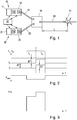
- Fig. 1 shows a transmitter for testing discontinuities in lines.
- Fig. 2 shows the sequence of frequencies for creating the pulse that is used to detect discontinuities.
- Fig. 3 shows the time course of the power of a pulse used for detection.
- Figures 4 and 5 show individual frequency components in the emitted and received laser light.
- Figure 5a shows a possible control of an electro-absorption modulator with an electrical frequency duplexer.
- Fig. 6 shows schematically the time course of the signal received by means of an electro-absorption modulator between the sending of the pulse and the detection of the reflection of the pulse at a discontinuity.
- Fig. 7 shows an alternative device that allows switching between a data transmission mode and a discontinuity detection mode.
- a time-of-flight measurement is typically used which is based on the fact that in the area of optical discontinuities 51 the light transmitted by the lasers is at least partially reflected on them.
- two laser units 10, 20 are used, which are connected to one another via a polarization beam splitter 40 and beam laser light with two different polarization directions into the optical channel to be examined.
- Fig. 1 the two laser units 10, 20 are shown, each having a laser 11, 21 and an electro-absorption modulator 12, 22 located in the beam path of the laser 11, 21.
- optical connections of the two electro-absorption modulators 12, 22 are connected to the two inputs 41, 42 of the polarization beam splitter 40 via optical connecting lines 13, 23.
- the output 43 of the polarization beam splitter 40 is connected to the optical channel 50.
- a test pulse is then generated by means of the two laser units 10, 20.
- the two laser units 10, 20 are controlled by a control unit 30, the control unit 30 specifying a laser current for each of the two lasers 11, 21 via which the respective laser frequencies f 1 , f 2 can be set.
- the laser frequencies f 1 , f 2 can also be set and stabilized by means of a temperature controller, whereby the setting of the frequencies is possible in a wider range.
- a temperature controller such a regulation of the temperature can also be used in order to exclude environmental influences which, for example, result from the drift of the room temperature.
- the light from the lasers 11, 21 is then at least partially reflected at the discontinuities 51.
- This circumstance can be determined by means of the electro-absorption modulators 12, 22, which have the advantageous property that they not only allow their light transmission to be regulated by impressing a signal on their electrical connection, but also provide a voltage at their electrical connection when light from meets the electro-absorption modulator on the outside.
- the light reflected at the discontinuity 51 and the laser light do not have exactly the same frequency, but rather differ from one another by a predetermined frequency value which is between 1 and 10 GHz.
- a predetermined frequency value which is between 1 and 10 GHz.
- an electrical signal is created, the frequency of which corresponds to the difference frequency of the two lasers 11, 21. If the same optical frequency were used for sending and receiving, the Electro-absorption modulator 12, 22 generated superimposition signal have a very low frequency, in particular have the frequency zero, whereby a very high electrical noise would be present overall.
- a modulation signal in the range of this difference frequency - also referred to as intermediate frequency - is generated at the electrical connection of the electro-absorption modulator 12, 22, which does not cause the noise interference described above is subject and can also be conditioned in a simple manner in the electronic field.
- the concrete creation of the test pulse T is detailed in Fig. 2 shown in more detail.
- the two lasers 11, 21 each emit light with a reference frequency f 1 , f 2 , the two reference frequencies f 1 , f 2 having a predetermined reference frequency difference ⁇ f from one another.
- This reference frequency difference ⁇ f can typically be set electrically, for example via a central control unit 30, and is in the range between 1 GHz and 10 GHz.
- V eam specified by the control unit 30 at the electrical connection of the two electro- absorption modulators 12, 22, this is shown in addition to the respective laser current of the laser 11, 21.
- the test pulse T is, as in Fig. 2 shown, divided into two equally long periods of time T 1 , T 2 .
- the duration of the test pulse is typically 1 to 10 ns. At a speed of light of about 2.10 8 m / s in the optical channel, this pulse length allows a spatial resolution of the reflected signals of about 20 cm to 2 m.
- the frequencies of the lasers 11, 21 are reset to the reference frequencies f 1 , f 2 .
- the voltage at the electrical connection of the two electroabsorption modulators 12, 22 is reset to a value at which the two electroabsorption modulators 12, 22 are no longer transparent to the laser light.
- the two lasers 11, 21 are operated with their respective reference frequencies f 1 , f 2 .
- the control unit 30 modifies the laser current of the respective lasers 11, 21 by a predetermined detuning frequency difference ⁇ f, in the present case it is increased.
- the temporal arrangement of the two time periods can also be interchanged, ie it is also possible that the second time period T 2 , in which the laser frequencies are detuned or modified, precedes the first time period T 1.
- the light output at the output of the two laser units 10, 20 corresponds approximately to that in FIG Fig. 3 shown temporal course.
- the transit time behavior of the light by measuring the reflected light in the area of the laser units 10, 20 it can be determined at which point in the optical channel 50 optical discontinuities 51 may be present.
- a major problem with this measurement is that due to the unpredictable polarization rotation in the optical channels 50, as occurs in particular in fiber optic lines, optical pulses generated by a laser 11, 21 with a predetermined reference frequency, which with a first polarization in an optical channel 50, are rotated in this optical channel 50 with regard to their polarization in an unpredictable manner and, in the worst case, are then transmitted to the respective other laser unit 10, 20 due to the polarization beam splitter 40.
- the two lasers 11, 21 each have different optical reference frequencies f 1 , f 2 that differ from one another by between 1 and 10 GHz, the reflected signal from the electro-absorption modulator 12, 22 cannot be received or cannot be received in the correct frequency range.
- the portion of the pulse T originating from the first laser 11 is transmitted back to the first modulated laser 10, and the portion originating from the second modulated laser 20 of the pulse is sent to the second modulated laser 20 transmitted back and superimposed in the relevant electro-absorption modulator 12, 22 with the laser light of the respective laser 11, 12, the frequency of which was reset to the reference frequency f 1 , f 2 after the pulse was emitted.
- the temporally first part of the pulse T which was generated during the time period T 1 , corresponds in terms of its frequency to the reference frequency f 1 , f 2 of the respective laser, so that an overlay signal in the low-frequency range is obtained at the output of the electro-absorption modulator 12, 22, which is subject to strong noise-related interference and cannot be further evaluated.
- the light generated during the second time period T 2 of the pulse T is offset by the detuning frequency difference ⁇ f compared to the light of the respective laser 11, 21, which was reset to the reference frequency f 1 , f 2 after the pulse T was generated electrical connection of the electro-absorption modulator 12, 22 to a voltage signal in the range of the frequency ⁇ f predetermined by the detuning frequency difference. This signal is not subject to interference caused by low frequencies and can easily be further processed electrically.
- the light generated by the first laser unit 10 reaches the second laser unit 20 and the light generated by the second laser unit 20 in each case with the first laser 10.
- the signals generated during the first time period with the reference frequency f 1 , f 2 are each generated with the reference frequency f 1 , f 2 of the laser of the respective other modulated laser 11, 21 is superimposed so that there is a frequency difference in the range of the reference frequency difference ⁇ f between the respective laser frequency f 1 , f 2 and the frequency of the reflected light. Since this reference frequency difference ⁇ f is in the range from 1 GHz to 10 GHz, it can advantageously be tapped at the electrical connection of the electro-absorption modulator 12, 22 of the respective laser unit 10, 20.
- the light of the pulse T which was generated during the second time period T 2 , can also be detected.
- the frequency of this signal may be too small to be detected without noise. Overall, these signal components can be neglected.
- the signal emitted by the second laser f 2 with a frequency f 2 + ⁇ f is superimposed on the first electro-absorption modulator 12 with the light produced by the first laser 11 with a frequency f 1.
- a signal in the range of an intermediate frequency of ⁇ f - / + ⁇ f can be detected on the electroabsorption modulator.
- the signal applied to the electrical connection of the electro-absorption modulator 12, 22 is shown in FIG Figures 4 and 5 shown at different times.
- Fig. 4 the frequency profile of the electrical signal at the input of the electro-absorption modulator 12, 22 at the time the pulse is generated. It can be seen here that the electroabsorption modulator 12, 22 is switched to be permeable for the generation of the pulse T due to an external excitation, so that the pulse T can be emitted via the optical channel 50.
- Fig. 5 the signal spectrum obtained on the basis of the received reflected pulse at the electrical connection of the electroabsorption modulator 12, 22 or several possible signal spectra in this regard is shown.
- the transmission signal is shown in dashed lines to illustrate the frequency difference to the transmission signal. It can be seen that due to the superimposition of the reflected portion of the pulse with the respective light of the laser 11, 21 signals in the range of the intermediate frequency are received, which are either in the range of the reference frequency difference ⁇ f or the detuning frequency difference ⁇ f.
- the common connection 31c, ie the common frequency connection, of a frequency duplexer 31 can be connected to the electrical connection of the electroabsorption modulators 12, 22 ( Figure 5a ).
- the low-frequency connection 31e of the frequency duplexer 31 is connected to a pulse generator 33 which generates the pulse T and which belongs to the control unit 30 and is controlled by it.
- the high-frequency connection 31h of the frequency duplexer 31 is connected to an evaluation unit 32 belonging to the control unit 30. Alternatively, the high-frequency Terminal 31h can be used directly for further processing of the reflected signal.
- the crossover frequency f T of the frequency duplexer can advantageously be selected in the intermediate range between the spectral components of the test pulse and the minimum of reference frequency difference ⁇ f and detuning frequency difference ⁇ f.
- a test pulse duration of 10 ns was selected so that the frequency components emanating from the test pulse are below a frequency of 0.2 GHz. Since both the reference frequency difference ⁇ f and the detuning frequency difference ⁇ f are in the range of 10 GHz, a crossover frequency of the frequency multiplexer can be set at around 0.5 GHz.
- Fig. 6 the time course of the light prevailing in the electroabsorption modulator 12, 22 is shown schematically.
- the light is received at a different point in time after the pulse T is emitted. Since the sensitivity of the pulse T is relevant at different times depending on the polarization rotation, the accuracy of the measurement is limited by the duration of the pulse T. If the speed of light in the optical channel 50 is 2.10 8 m / s and the pulse length is 10 ns, the result is a resolution accuracy of 200 cm.
- the distance between the laser units 10, 20 and the discontinuity 51 can be deduced, taking into account the resolution accuracy.
- a particularly preferred embodiment of the invention is in Fig. 7 shown in more detail.
- Two different control units 30, 60 are provided, with the control unit 30 corresponding to the control unit 30 described in connection with the previous exemplary embodiment and the other control unit functioning as a transmission control unit 60, which is designed to supply the electro-absorption modulators 12, 22 for outputting data transmission signals cause and detect received signals at the electrical connection of the electroabsorption modulator 12, 22.
- this transmission control unit 60 is also designed to modify the laser current of the two lasers 11, 21 if this should be necessary for the data transmission.
- Both the control unit 30 and the transmission control unit 60 thus have a control connection for controlling the laser current, as well as an output for connection to the electrical connection of the electro-absorption modulator 12, 22.
- the respective connections of the control unit 30 or the transmission control unit 60 are forwarded to a switching unit 70, which makes it possible to connect either the control unit 30 or the transmission control unit 60 to the two laser units 10, 20 in order to alternate between the two functions in any cycle ratio without changing the opto -electronic hardware to run.
- the transmission control unit 60 may typically be connected to a digital computer, telephone, antenna, or similar device.
Description
Die Erfindung betrifft ein Verfahren sowie eine Vorrichtung zur Detektion von Diskontinuitäten in einem optischen Kanal, insbesondere einer Glasfaserleitung.The invention relates to a method and a device for detecting discontinuities in an optical channel, in particular a glass fiber line.
Die
Aus der
Aus dem Stand der Technik ist eine Vielzahl von unterschiedlichen Prüfverfahren bekannt, mit denen Störungen in Glasfasernetzen auf einfache Weise aufgefunden werden können. Typischerweise ist dabei vorgesehen, dass im Falle einer aufgetretenen Störung, wenn vermutet wird, dass Beschädigungen am Glasfasernetzwerk vorliegen, zu dem Endpunkt der Glasfaserleitung befindlichen Transmitter zusätzlich ein Überprüfungsgerät an das Glasfasernetzwerk angeschlossen wird, mit dem eine Prüfung der Qualität des optischen Kanals möglich ist. Insbesondere können mit einer derartigen aus dem Stand der Technik bekannten Prüfung Diskontinuitäten im betreffenden optischen Kanal aufgefunden werden, die beispielsweise von Kabelbrüchen, schlechten Steckverbindungen oder ähnlichen mechanischen Beeinträchtigungen der Glasfaserleitung herrühren.A large number of different test methods are known from the prior art with which faults in fiber optic networks can be found in a simple manner. Typically, in the event of a malfunction, if it is suspected that there is damage to the fiber optic network, a transmitter located at the end point of the fiber optic line is additionally connected to the fiber optic network, with which the quality of the optical channel can be checked. In particular, with such a test known from the prior art, discontinuities in the relevant optical channel can be found, which result, for example, from broken cables, poor plug connections or similar mechanical impairments of the fiber optic line.
Dabei besteht jedoch gerade bei weit verteilten Glasfasernetzen das Problem, dass mit dem zusätzlichen temporären Anschluss eines Prüfgeräts zu dem für die Kommunikation verwendeten Transmitter am Endpunkt des Glasfasernetzes ein erheblicher Arbeitsaufwand verbunden ist.However, especially with widely distributed fiber optic networks, the problem is that the additional temporary connection of a test device to the transmitter used for communication at the end point of the fiber optic network entails a considerable amount of work.
Aus dem Stand der Technik ist es bekannt, unterschiedliche Transmitter zum Empfangen und Übermitteln von Daten aus einem Glasfasernetzwerk zu verwenden. Die Erfindung macht sich den Umstand zu Nutze, dass eine Vielzahl von Transmittern bereits ohnedies extern modulierte Laser aufweist, die auch für die Prüfung von Diskontinuitäten im optischen Kanal herangezogen werden können.It is known from the prior art to use different transmitters for receiving and transmitting data from a fiber optic network. The invention makes use of the fact that a large number of transmitters already have externally modulated lasers which can also be used to test discontinuities in the optical channel.
Die Erfindung sieht dabei ein Verfahren vor, bei dem
- die Referenzfrequenzen der beiden Laser einen vorgegebenen Referenzfrequenzunterschied, insbesondere in einem Bereich von 1 GHz bis 10 GHz, aufweist,
- die optischen Anschlüsse des Elektroabsorptionsmodulators an die beiden Eingänge eines Polarisationsstrahlteilers geführt sind und der Ausgang des Polarisationsstrahlteilers an den optischen Kanal angeschlossen ist,
- ein Testpuls, insbesondere mit einer Länge von 1 bis 10 ns, gleichzeitig an die beiden Elektroabsorptionsmodulatoren angelegt wird und derart während der Zeit des Testpulses Laserlicht von den Lasern durch die jeweiligen Elektroabsorptionsmodulatoren transmittiert wird,
- der Testpuls in zwei, insbesondere gleich lange, Zeitspannen geteilt wird, und während der ersten Zeitspanne die Laser mit ihrer jeweiligen Referenzfrequenz betrieben werden, und während der zweiten Zeitspanne die Emissionsfrequenzen der Laser gegenüber den Referenzfrequenzen, insbesondere durch Modifikation des jeweiligen Laserstroms, vorzugsweise um eine Frequenz von 1 bis 10 GHz, um einen vorgegebenen Verstimmungsfrequenzunterschied verstimmt werden,
- die beiden Elektroabsorptionsmodulatoren nach dem Ende des Testpulses in einen lichtundurchlässigen Zustand versetzt werden, wobei die Elektroabsorptionsmodulatoren von einer Seite von den Lasern mit ihrer jeweiligen Referenzfrequenz beleuchtet werden und gleichzeitig das über den optischen Kanal an einer Diskontinuität reflektierte Licht des Testpulses absorbieren, und
- die beiden Elektroabsorptionsmodulatoren einen dem bei ihnen insgesamt einfallenden Licht entsprechenden Fotostrom an ihrem optischen Anschluss zur Verfügung stellen, und die so ermittelten Fotoströme, gegebenenfalls nach Vornahme einer Filterung und/oder Verstärkung, als charakteristisch für den jeweiligen Kanal angesehen werden.
- the reference frequencies of the two lasers have a predetermined reference frequency difference, in particular in a range from 1 GHz to 10 GHz,
- the optical connections of the electro-absorption modulator are routed to the two inputs of a polarization beam splitter and the output of the polarization beam splitter is connected to the optical channel,
- a test pulse, in particular with a length of 1 to 10 ns, is applied simultaneously to the two electroabsorption modulators and in this way laser light from the lasers is transmitted through the respective electroabsorption modulators during the time of the test pulse,
- the test pulse is divided into two, in particular equally long, time spans, and during the first time span the lasers are operated at their respective reference frequencies, and during the second time span the emission frequencies of the lasers compared to the reference frequencies, in particular by modifying the respective laser current, preferably by one Frequency from 1 to 10 GHz to be detuned by a specified detuning frequency difference,
- the two electroabsorption modulators are placed in an opaque state after the end of the test pulse, the electroabsorption modulators being illuminated from one side by the lasers with their respective reference frequency and at the same time absorbing the light of the test pulse reflected via the optical channel at a discontinuity, and
- the two electro-absorption modulators provide a photocurrent corresponding to the total incident light at their optical connection, and the photocurrents determined in this way, if necessary after filtering and / or amplification, are regarded as characteristic of the respective channel.
Die Erfindung löst die Aufgabe mit einer Vorrichtung
- die Referenzfrequenzen der beiden Laser einen vorgegebenen Referenzfrequenzunterschied, insbesondere in einem Bereich von 1 GHz bis 10 GHz, aufweisen,
- die optischen Anschlüsse der Elektroabsorptionsmodulatoren an die beiden Eingänge eines Polarisationsstrahlteilers geführt sind und der Ausgang des Polarisationsstrahlteilers an den optischen Kanal angeschlossen ist,
- wobei die Vorrichtung eine Steuereinheit umfasst, wobei die Steuereinheit einen Pulsgenerator umfasst, der zur Erstellung eines Testpulses an den elektrischen Anschlüssen der beiden Elektroabsorptionsmodulatoren und zum gleichzeitigen Anlegen eines Testpulses, insbesondere mit einer Länge von 1 bis 10 ns, ausgebildet ist, wobei die Steuereinheit dazu ausgebildet ist, den Laserstrom der beiden Laser während der Abgabe des Testpulses derart zu steuern, dass während einer ersten Zeitspanne die Laser mit ihrer jeweiligen Referenzfrequenz betrieben werden und während einer zweiten, insbesondere gleich langen und/oder auf die erste Zeitspanne folgenden oder dieser unmittelbar vorangehenden, zweiten Zeitspanne die Frequenzen der Laser gegenüber den Referenzfrequenzen, vorzugsweise um eine Frequenz von 1 bis 10 GHz, um einen vorgegebenen Verstimmungsfrequenzunterschied verstimmt sind, und
- die Steuereinheit dazu ausgebildet ist, nach dem Ende des Testpulses die Laser bei ihren Referenzfrequenzen weiter zu betreiben und die beiden Elektroabsorptionsmodulatoren in einen absorbierenden Zustand zu versetzen, bei dem die Elektroabsorptionsmodulatoren sowohl das Laserlicht der beiden Laser als auch allenfalls reflektiertes Licht vom optischen Kanal absorbieren und am elektrischen Anschluss einen dem bei ihnen insgesamt einfallenden Licht entsprechenden Fotostrom zur Verfügung stellen,
- die Steuereinheit dazu ausgebildet ist, die elektrischen Anschlüsse der beiden Elektroabsorptionsmodulatoren nach dem Ende des Testpulses zu überwachen.
- the reference frequencies of the two lasers have a predetermined reference frequency difference, in particular in a range from 1 GHz to 10 GHz,
- the optical connections of the electro-absorption modulators are routed to the two inputs of a polarization beam splitter and the output of the polarization beam splitter is connected to the optical channel,
- the device comprising a control unit, the control unit comprising a pulse generator which is designed to generate a test pulse at the electrical connections of the two electroabsorption modulators and to simultaneously apply a test pulse, in particular with a length of 1 to 10 ns, the control unit for this purpose is designed to control the laser current of the two lasers during the delivery of the test pulse in such a way that the lasers are operated at their respective reference frequency during a first period of time and during a second, in particular of the same length and / or following or immediately preceding the first period , the second time period the frequencies of the lasers are detuned with respect to the reference frequencies, preferably by a frequency of 1 to 10 GHz, by a predetermined detuning frequency difference, and
- the control unit is designed to continue to operate the lasers at their reference frequencies after the end of the test pulse and to put the two electroabsorption modulators in an absorbing state in which the electroabsorption modulators absorb both the laser light of the two lasers and any light reflected from the optical channel and provide a photocurrent corresponding to the total amount of incident light at the electrical connection,
- the control unit is designed to monitor the electrical connections of the two electro-absorption modulators after the end of the test pulse.
Eine besonders einfache Variante, mit der am Modulationsanschluss des Elektroabsorptionsmodulators einlangende und ausgehende Signale von einander getrennt übertragen werden können, sieht vor, dass
- am elektrischen Anschluss zumindest eines der Elektroabsorptionsmodulatoren der Common-Anschluss eines Frequenz-Duplexers angeschlossen ist,
- wobei der niederfrequente Anschluss des Frequenz-Duplexers an einen den Testpuls generierenden Pulsgenerator angeschlossen ist, und
- der hochfrequente Anschluss des Frequenz-Duplexers an eine Auswerteeinheit angeschlossen ist oder das charakteristische Signal an diesem Anschluss bereitgestellt anliegt.
- the common connection of a frequency duplexer is connected to the electrical connection of at least one of the electro-absorption modulators,
- wherein the low-frequency connection of the frequency duplexer is connected to a pulse generator generating the test pulse, and
- the high-frequency connection of the frequency duplexer is connected to an evaluation unit or the characteristic signal is provided at this connection.
Eine besonders vorteilhafte Auswahl der Trennfrequenz des Frequenz-Multiplexers, mit der eine vorteilhafte Unterscheidung der Frequenz möglich ist, sieht vor, dass die Trennfrequenz des Frequenz-Duplexers zwischen den spektralen Anteilen des Testpulses und dem Minimum von Referenzfrequenzunterschied und Verstimmungsfrequenzunterschied gewählt wird.A particularly advantageous selection of the crossover frequency of the frequency multiplexer, with which an advantageous differentiation of the frequency is possible, provides that the Crossover frequency of the frequency duplexer between the spectral components of the test pulse and the minimum of reference frequency difference and detuning frequency difference is selected.
Um die erfindungsgemäße Schaltung auf einfache Weise und ohne zusätzlichen Serviceaufwand sowohl zur Datenübertragung als auch zur Prüfung des optischen Übertragungskanals nutzen zu können, kann vorgesehen sein, dass zusätzlich eine Übertragungssteuerungseinheit vorgesehen ist, die dazu ausgebildet ist, die Lasereinheiten zur Datenübertragung sowie zum Datenempfang zu veranlassen und, die Übertragungssteuerungseinheit vorzugsweise mit einem weiteren Netzwerk zur Datenübertragung verbunden ist, und
eine Umschalteeinheit vorgesehen ist, die dazu ausgebildet ist, die Ansteuerung der Lasereinheiten durch die Steuereinheit oder durch die Übertragungssteuerungseinheit zu ermöglichen.In order to be able to use the circuit according to the invention in a simple manner and without additional service expenditure both for data transmission and for checking the optical transmission channel, a transmission control unit can also be provided which is designed to cause the laser units to transmit and receive data and, the transmission control unit is preferably connected to a further network for data transmission, and
a switchover unit is provided which is designed to enable the laser units to be activated by the control unit or by the transmission control unit.
Eine bevorzugte Ausführungsform der Erfindung wird anhand der folgenden Zeichnungsfiguren ohne Beschränkung des allgemeinen erfinderischen Gedankens näher dargestellt.A preferred embodiment of the invention is illustrated in more detail with reference to the following drawing figures without restricting the general inventive concept.
Zur Bestimmung von optischen Diskontinuitäten 51 im optischen Kanal 50 wird typischerweise eine Lichtlaufzeitmessung verwendet, die auf dem Umstand basiert, dass im Bereich von optischen Diskontinuitäten 51 das von den Lasern übermittelte Licht an diesen zumindest teilweise reflektiert wird.To determine
Um Auswirkungen von polarisationsbedingten Drehungen auf die Messung möglichst auszuschließen, werden zwei Lasereinheiten 10, 20 verwendet, die über einen Polarisationsstrahlteiler 40 miteinander verbunden sind und Laserlicht mit zwei unterschiedlichen Polarisationsrichtungen in den zu untersuchenden optischen Kanal strahlen. In
Die optischen Anschlüsse der beiden Elektroabsorptionsmodulatoren 12, 22 sind über optische Verbindungsleitungen 13, 23 an die beiden Eingänge 41, 42 des Polarisationsstrahlteilers 40 angeschlossen. Der Ausgang 43 des Polarisationsstrahlteilers 40 ist an den optischen Kanal 50 angeschlossen.The optical connections of the two electro-
Zur Detektion von Diskontinuitäten 51 im optischen Kanal 50 wird in weiterer Folge mittels der beiden Lasereinheiten 10, 20 ein Testpuls erstellt. Typischerweise werden die beiden Lasereinheiten 10, 20 von einer Steuereinheit 30 angesteuert, wobei die Steuereinheit 30 für die beiden Laser 11, 21 jeweils einen Laserstrom vorgibt, über den die jeweiligen Laserfrequenzen f1, f2 einstellbar sind. Zusätzlich oder alternativ können die Laserfrequenzen f1, f2 auch mittels eines Temperaturreglers eingestellt und stabilisiert werden, wodurch die Einstellung der Frequenzen in einem weiteren Bereich möglich ist. Eine solche Regelung der Temperatur kann auch verwendet werden, um Umwelteinflüsse auszuschließen, die beispielsweise vom Drift der Raumtemperatur herrühren.In order to detect
Anschließend wird das Licht der Laser 11, 21 an den Diskontinuitäten 51 zumindest teilweise reflektiert. Dieser Umstand kann mittels der Elektroabsorptionsmodulatoren 12, 22 festgestellt werden, die die vorteilhafte Eigenschaft aufweisen, dass sie nicht bloß die Regelung ihrer Lichtdurchlässigkeit durch Aufprägen eine Signals an ihrem elektrischen Anschluss erlauben, sondern auch an ihrem elektrischen Anschluss dann eine Spannung bereitstellen, wenn Licht von außen auf den Elektroabsorptionsmodulator trifft.The light from the
Besonders vorteilhaft ist es, wenn das an der Diskontinuität 51 reflektierte Licht und das Laserlicht nicht exakt dieselbe Frequenz haben, sondern voneinander um einen vorgegebenen Frequenzwert, der zwischen 1 und 10 GHz liegt, voneinander abweichen. In diesem Fall wird nämlich aufgrund einer quadratischen Detektionskennlinie des Elektroabsorptionsmodulators 12, 22 ein elektrisches Signal erstellt, dessen Frequenz der Differenzfrequenz der beiden Laser 11, 21 entspricht. Würde nämlich für Aussenden und Empfangen dieselbe optische Frequenz verwendet, so würde das vom Elektroabsorptionsmodulator 12, 22 erstellte Überlagerungssignal eine sehr geringe Frequenz aufweisen, insbesondere die Frequenz Null aufweisen, wodurch insgesamt ein sehr hohes elektrisches Rauschen vorhanden wäre. Werden hingegen zur Detektion optische Signale verwendet, die voneinander um bestimmte Frequenzen, beispielsweise im Bereich 1 GHz, abweichen, so entsteht am elektrischen Anschluss des Elektroabsorptionsmodulators 12, 22 ein Modulationssignal im Bereich dieser Differenzfrequenz - auch als Zwischenfrequenz bezeichnet - die den zuvor beschriebenen Rauschstörungen nicht unterliegt und auch in einfacher Weise im elektronischen Bereich konditioniert werden kann.It is particularly advantageous if the light reflected at the
Die konkrete Erstellung des Testpulses T ist im Detail in
Nach der Abgabe des Testpulses werden die Frequenzen der Laser 11, 21 auf die Referenzfrequenzen f1, f2 zurückgesetzt. Die Spannung am elektrischen Anschluss der beiden Elektroabsorptionsmodulatoren 12, 22 wird auf einen Wert zurückgesetzt, bei dem die beiden Elektroabsorptionsmodulatoren 12, 22 für das Laserlicht nicht mehr durchsichtig sind.After the test pulse has been emitted, the frequencies of the
Während der ersten Zeitspanne T1 werden die beiden Laser 11, 21 mit ihrer jeweiligen Referenzfrequenz f1, f2 betrieben. Während der zweiten Zeitspanne T2 wird mittels der Steuereinheit 30 der Laserstrom der jeweiligen Laser 11, 21 um einen vorgegebenen Verstimmungsfrequenzunterschied Δf modifiziert, im vorliegenden Fall erhöht. Die zeitliche Anordnung der beiden Zeitspannen kann auch vertauscht sein, dh es ist auch möglich, dass die zweite Zeitspanne T2, in der die Laserfrequenzen verstimmt bzw modifiziert sind, der ersten Zeitspanne T1 vorangeht.During the first time period T 1 , the two
Wie aus
Ein wesentliches Problem dieser Messung besteht darin, dass aufgrund der nicht vorhersagbaren Polarisationsdrehung in den optischen Kanälen 50, wie sie insbesondere bei Glasfaserleitungen auftritt, von einem Laser 11, 21 mit einer vorgegebenen Referenzfrequenz erstellte optische Pulse, die mit einer ersten Polarisation in einen optischen Kanal 50 geleitet werden, in diesem optischen Kanal 50 hinsichtlich ihrer Polarisation auf unvorhersehbare Weise verdreht werden und im ungünstigsten Fall anschließend aufgrund des Polarisationsstrahlteilers 40 an die jeweils andere Lasereinheit 10, 20 übermittelt werden. Da im vorliegenden Fall jedoch die beiden Laser 11, 21 jeweils unterschiedliche optische Referenzfrequenzen f1, f2 aufweisen, die voneinander um zwischen 1 bis 10 GHz abweichen, kann das reflektierte Signal vom Elektroabsorptionsmodulator 12, 22 nicht bzw nicht im richtigen Frequenzbereich empfangen werden. Grund hierfür ist der Umstand, dass aufgrund des in
Wird also beispielsweise vom ersten Laser 11 Licht ausgesendet, so erfolgt dies während der ersten Zeitspanne T1 des Pulses T mit einer Frequenz f1, und während der zweiten Zeitspanne T2 des Pulses T mit einer Frequenz f1 + Δf. Ebenso wird vom zweiten Laser 21 während der ersten Zeitspanne t1 ein Signal mit der zweiten Referenzfrequenz f2 abgesandt, und in der zweiten Zeitspanne T2 wird diese Frequenz auf f2 + Δf erhöht. Aufgrund der möglichen Polarisationsdrehung dieser Signale im optischen Kanal 50 kann nicht vorhergesagt werden, bei welcher der Lasereinheiten 10, 20 der so erstellte Impuls nach einer erfolgten Reflektion an einer Diskontinuität 51 zurück erhalten wird.If, for example, light is emitted by the
Geht man davon aus, dass die vom Kanal 50 und der optischen Diskontinuität 51 insgesamt bewirkte Polarisationsdrehung Null ist, wird der vom ersten Laser 11 herrührende Anteil des Pulses T an den ersten modulierten Laser 10 zurück übermittelt, und der vom zweiten modulierten Laser 20 herrührende Anteil des Pulses wird an den zweiten modulierten Laser 20 zurück übermittelt und im betreffenden Elektroabsorptionsmodulator 12, 22 mit dem Laserlicht des jeweiligen Lasers 11, 12, dessen Frequenz nach der Abgabe des Pulses wieder auf die Referenzfrequenz f1, f2 zurückgestellt wurde, überlagert.Assuming that the total polarization rotation caused by the
Der zeitlich gesehen erste Teil des Pulses T, der während der Zeitspanne T1 erstellt wurde, entspricht hinsichtlich seiner Frequenz der Referenzfrequenz f1, f2 des jeweiligen Lasers, sodass am Ausgang des Elektroabsorptionsmodulators 12, 22 ein Überlagerungssignal im niederfrequenten Bereich erhalten wird, das starken rauschbedingten Störungen unterliegt und nicht weiter ausgewertet werden kann. Das während der zweiten Zeitspanne T2 des Pulses T erstellte Licht ist gegenüber dem Licht des jeweiligen Lasers 11, 21, das nach der Erstellung es Pulses T wieder auf die Referenzfrequenz f1, f2 zurückgestellt wurde, um den Verstimmungsfrequenzunterschied Δf versetzt, was am elektrischen Anschluss des Elektroabsorptionsmodulators 12, 22 zu einem Spannungssignal im Bereich der durch den Verstimmungsfrequenzunterschied vorgegebenen Frequenz Δf bewirkt. Dieses Signal unterliegt keinen niederfrequenzbedingten Störungen und kann elektrisch einfach weiterverarbeitet werden.The temporally first part of the pulse T, which was generated during the time period T 1 , corresponds in terms of its frequency to the reference frequency f 1 , f 2 of the respective laser, so that an overlay signal in the low-frequency range is obtained at the output of the electro-
Für den Fall, dass das optische Signal auf seinem Weg durch den optischen Kanal 50 zur Diskontinuität 51 und aufgrund der Reflektion wieder zurück zum Laser hinsichtlich seiner Polarisation verändert wurde und - im ungünstigsten Fall orthogonal vorliegt, langt das von der ersten Lasereinheit 10 erstellte Licht bei der zweiten Lasereinheit 20 ein und das von der zweiten Lasereinheit 20 erstellte Licht jeweils beim ersten Laser 10. In diesem Fall werden die während der ersten Zeitspanne mit der Referenzfrequenz f1, f2 erstellten Signale jeweils mit der Referenzfrequenz f1, f2 des Lasers des jeweils anderen modulierten Lasers 11, 21 überlagert, sodass zwischen der jeweiligen Laserfrequenz f1, f2 und der Frequenz des reflektierten Lichts ein Frequenzunterschied im Bereich des Referenzfrequenzunterschieds δf vorliegt. Da dieser Referenzfrequenzunterschied δf im Bereich von 1 GHz bis 10 GHz liegt, lässt dieser sich vorteilhaft am elektrischen Anschluss des Elektroabsorptionsmodulators 12, 22 der jeweiligen Lasereinheit 10, 20 abgreifen.In the event that the polarization of the optical signal was changed on its way through the
In Einzelfällen kann zusätzlich auch das Licht des Pulses T, das während der zweiten Zeitspanne T2 erstellt wurde, detektiert werden. Im vorliegenden Fall wird das vom ersten Laser mit einer Frequenz f1 + Δf während der zweiten Zeitspanne T2 ausgesandte Signal mit dem Lasersignal des zweiten Lasers 21 mit der Referenzfrequenz f2 = f1 + δf überlagert, sodass ein elektrisches Ausgangssignal am Ausgang des Elektroabsorptionsmodulators 22 vorliegt, das eine Frequenz von δf - Δf aufweist. Je nach Vorgabe der Frequenzen ist die Frequenz dieses Signals jedoch möglicherweise zu klein, um rauschfrei detektiert zu werden. Insgesamt können diese Signalanteile vernachlässigt werden. Das vom zweiten Laser f2 mit einer Frequenz f2 + Δf abgegebene Signal wird am ersten Elektroabsorptionsmodulator 12 mit dem vom ersten Laser 11 erstellten Licht mit einer Frequenz f1 überlagert. Am Elektroabsorptionsmodulator kann ein Signal im Bereich der einer Zwischenfrequenz von Δf -/+ δf detektiert werden.In individual cases, the light of the pulse T, which was generated during the second time period T 2 , can also be detected. In the present case, the signal emitted by the first laser with a frequency f 1 + Δf during the second time period T 2 is combined with the laser signal of the
Das am elektrischen Anschluss des Elektroabsorptionsmodulators 12, 22 anliegende Signal ist hinsichtlich seines Frequenzverlaufs in den
Dabei zeigt
In
Zum einfachen Trennen des einlangenden Signals und des ausgehenden Signals sowie zur Erstellung eines separaten Eingangs und Ausgangs am Elektroabsorptionsmodulator 12, 22 kann am elektrischen Anschluss der Elektroabsorptionsmodulatoren 12, 22 der Common-Anschluss 31c, d.h. der gemeinsame Frequenzanschluss, eines Frequenz-Duplexers 31 angeschlossen sein (
Im vorliegenden Fall wurde eine Testpulsdauer von 10 ns gewählt, sodass die vom Testpuls ausgehenden Frequenzanteile unter einer Frequenz von 0.2 GHz liegen. Da sowohl von Referenzfrequenzunterschied δf als auch Verstimmungsfrequenzunterschied Δf im Bereich von 10 GHz liegen, kann eine Trennfrequenz des Frequenz-Multiplexers bei etwa 0.5 GHz festgelegt werden.In the present case, a test pulse duration of 10 ns was selected so that the frequency components emanating from the test pulse are below a frequency of 0.2 GHz. Since both the reference frequency difference Δf and the detuning frequency difference Δf are in the range of 10 GHz, a crossover frequency of the frequency multiplexer can be set at around 0.5 GHz.
In
Eine besonders bevorzugte Ausführung der Erfindung ist in
Sowohl die Steuereinheit 30 als auch die Übertragungssteuerungseinheit 60 weisen somit einen Steueranschluss zur Steuerung des Laserstroms, sowie einen Ausgang zum Anschluss an den elektrischen Anschluss des Elektroabsorptionsmodulators 12, 22 auf.Both the
Die jeweiligen Anschlüsse der Steuereinheit 30 bzw. der Übertragungssteuerungseinheit 60 werden an eine Umschalteinheit 70 weitergeleitet, die es ermöglicht, an die beiden Lasereinheiten 10, 20 entweder die Steuereinheit 30 oder die Übertragungssteuerungseinheit 60 anzuschließen um abwechselnd in einem beliebigen Taktverhältnis beide Funktionen ohne Wechsel der opto-elektronischen Hardware ausführen zu können. Die Übertragungssteuerungseinheit 60 kann typischerweise mit einem Digitalrechner, Telefon, Antenne oder einem ähnlichen Gerät verbunden sein.The respective connections of the
Claims (5)
- Method for detecting discontinuities (51) in an optical channel (50), in particular in a fibre optic cable,- having two laser units (10, 20), each comprising a laser (11, 21) and an electroabsorption modulator (12, 22),- wherein the reference frequencies (f1, f2) of the two lasers (11, 21) has a predetermined reference frequency difference (δf), in particular in a range from 1 GHz to 10 GHz,- wherein the optical ports (120, 12p; 220, 22p) of the electroabsorption modulator (12, 22) are guided to the two inputs (41, 42) of a polarisation beam splitter (40) and the output (43) of the polarisation beam splitter (40) is connected to the optical channel (50),- wherein a test pulse (T), in particular with a length of 1 to 10 ns, is applied simultaneously to the two electroabsorption modulators (12, 22) and, in such a way, during the time of the test pulse (T) laser light from the lasers (11, 21) is transmitted through the respective electroabsorption modulators (12, 22),- wherein the test pulse (T) is divided into two, in particular equally long, time periods (T1, T2), and during the first time period (T1) the lasers (11, 21) are operated at their respective reference frequency (f1, f2), and during the second time period (T2) the emission frequencies of the lasers are detuned relative to the reference frequencies, in particular by modification of the respective laser current, preferably by a frequency of 1 to 10 GHz, by a predetermined detuning frequency difference (Δf),- wherein the two electroabsorption modulators (12, 22) are switched to an opaque state after the end of the test pulse (T), wherein the electroabsorption modulators (12, 22) are illuminated from one side by the lasers (11, 22) at their respective reference frequency (f1, f2) and simultaneously absorb the light of the test pulse (T) reflected via the optical channel (50) at a discontinuity (51), and- wherein the two electroabsorption modulators (12, 22) make available at their optical port (120, 12p; 220, 22p) a photocurrent corresponding to the total light incident on them, and the photocurrents thus determined, optionally after filtering and/or amplification, are considered characteristic of the respective channel.
- Device for detecting discontinuities (51) in an optical channel (50), in particular a fibre optic cable,- having two laser units (10, 20), each comprising a laser (11, 21) and an electroabsorption modulator (12, 22),- wherein the reference frequencies (f1, f2) of the two lasers (11, 21) have a predetermined reference frequency difference (δf), in particular in a range from 1 GHz to 10 GHz,- wherein the optical ports (120, 12p; 220, 22p) of the electroabsorption modulators (12, 22) are guided to the two inputs (41, 42) of a polarisation beam splitter (40) and the output (43) of the polarisation beam splitter (40) is connected to the optical channel (50),- wherein the device comprises a control unit (30), wherein the control unit (30) comprises a pulse generator which is designed to generate a test pulse at the electrical ports (12e; 22e) of the two electroabsorption modulators (12, 22) and to simultaneously apply a test pulse, in particular with a length of 1 to 10 ns, wherein the control unit (30) is designed to control the laser current of the two lasers (11, 21) during the emission of the test pulse (T) in such a way that during a first time period (T1) the lasers (11, 21) are operated at their respective reference frequency (f1, f2) and during a second time period (T2), which is in particular equally long and/or follows or immediately precedes the first time period (T1), the frequencies of the lasers (11, 21) are detuned relative to the reference frequencies (f1, f2), preferably by a frequency of 1 to 10 GHz, by a predetermined detuning frequency difference (Δf), and- wherein the control unit (30) is designed to continue to operate the lasers (11, 21) at their reference frequencies (f1, f2) after the end of the test pulse and to switch the two electroabsorption modulators (12, 22) to an absorbing state in which the electroabsorption modulators (12, 22) absorb both the laser light of the two lasers (11, 21) and any reflected light from the optical channel (50) and make available at the electrical port a photocurrent corresponding to the total light incident on them,- wherein the control unit (30) is designed to monitor the electrical ports (12e; 22e) of the two electroabsorption modulators (12, 22) after the end of the test pulse (T).
- Device according to claim 2,- wherein the common port (31c) of a frequency duplexer (31) is connected to the electrical port of at least one of the electroabsorption modulators (12, 22),- wherein the low-frequency port (311) of the frequency duplexer (31) is connected to a pulse generator (33) generating the test pulse (T), and- wherein the high-frequency port (31h) of the frequency duplexer (31) is connected to an evaluation unit (32) or the characteristic signal is provided at the high-frequency port (31h).
- Device according to claim 3, wherein the crossover frequency of the frequency duplexer is selected from among the spectral components of the test pulse (T) and the minimum of the reference frequency difference (δf) and the detuning frequency difference (Δf).
- Device according to any of claims 2 to 4, wherein a transmission control unit (60) is additionally provided which is designed to cause the laser units (10, 20) to transmit data as well as to receive data and wherein the transmission control unit (60) is preferably connected to a further network for data transmission, and
wherein a switching unit (70) is provided which is designed to enable the control unit (30) or the transmission control unit (60) to control the laser units (10, 20).
Applications Claiming Priority (1)
| Application Number | Priority Date | Filing Date | Title |
|---|---|---|---|
| ATA50847/2018A AT521463B1 (en) | 2018-10-03 | 2018-10-03 | Method for the detection of discontinuities in an optical channel, in particular in the case of an optical fiber line |
Publications (2)
| Publication Number | Publication Date |
|---|---|
| EP3633877A1 EP3633877A1 (en) | 2020-04-08 |
| EP3633877B1 true EP3633877B1 (en) | 2021-03-24 |
Family
ID=68109258
Family Applications (1)
| Application Number | Title | Priority Date | Filing Date |
|---|---|---|---|
| EP19200901.7A Active EP3633877B1 (en) | 2018-10-03 | 2019-10-01 | Method for detecting discontinuities in an optical channel, especially in a fibre optic line |
Country Status (3)
| Country | Link |
|---|---|
| US (1) | US10928273B2 (en) |
| EP (1) | EP3633877B1 (en) |
| AT (1) | AT521463B1 (en) |
Families Citing this family (3)
| Publication number | Priority date | Publication date | Assignee | Title |
|---|---|---|---|---|
| CN116325557A (en) * | 2020-10-09 | 2023-06-23 | 华为技术有限公司 | Apparatus and method for generating optical signals in an optical communication network |
| US20220247488A1 (en) * | 2021-02-02 | 2022-08-04 | Huawei Technologies Co., Ltd. | Method and system inspecting fibered optical communication paths |
| CN116131940B (en) * | 2023-04-17 | 2023-07-07 | 广州赛宝计量检测中心服务有限公司 | Calibration device, system and method for optical discontinuity tester |
Family Cites Families (12)
| Publication number | Priority date | Publication date | Assignee | Title |
|---|---|---|---|---|
| JP2589345B2 (en) * | 1988-06-24 | 1997-03-12 | 日本電信電話株式会社 | Method and apparatus for evaluating characteristics of optical fiber |
| US5394260A (en) * | 1992-02-03 | 1995-02-28 | Kokusai Denshin Denwa Kabushiki Kaisha | Optical pulse generator |
| DE19641441A1 (en) * | 1996-10-08 | 1998-04-09 | Siemens Ag | Optical dispersion measurement by phase shift of back scattered light |
| GB2404992B (en) * | 2003-08-12 | 2006-12-27 | Agilent Technologies Inc | Electro-absorption modulation of optical signals |
| JP5380647B2 (en) * | 2007-05-25 | 2014-01-08 | アンリツ株式会社 | Optical signal sampling apparatus and method, and optical signal monitoring apparatus and method using the same |
| JP5495506B2 (en) * | 2008-05-13 | 2014-05-21 | キヤノン株式会社 | Laser apparatus and optical tomographic imaging apparatus |
| JP5322184B2 (en) * | 2008-11-27 | 2013-10-23 | ニューブレクス株式会社 | Distributed optical fiber sensor |
| US9281893B2 (en) * | 2013-10-23 | 2016-03-08 | Lumentum Operations Llc | In-service monitoring of a fiberoptic network |
| JP6199341B2 (en) * | 2015-06-11 | 2017-09-20 | アンリツ株式会社 | Sampling circuit, sampling method, sampling oscilloscope and waveform display method |
| CN104980225B (en) * | 2015-07-24 | 2017-10-03 | 武汉光迅科技股份有限公司 | A kind of optical module of the interior transparent transmission monitoring signal of band based on amplitude modulation(PAM) |
| EP3312582B1 (en) | 2016-10-20 | 2020-02-26 | Xieon Networks S.à r.l. | Otdr using an electro-absorption modulator for both pulse forming and pulse detection |
| US10673528B1 (en) * | 2019-02-25 | 2020-06-02 | Huawei Technologies Co., Ltd. | Methods and apparatuses for controlling optical signals in optical networks |
-
2018
- 2018-10-03 AT ATA50847/2018A patent/AT521463B1/en active
-
2019
- 2019-10-01 EP EP19200901.7A patent/EP3633877B1/en active Active
- 2019-10-03 US US16/592,098 patent/US10928273B2/en active Active
Non-Patent Citations (1)
| Title |
|---|
| None * |
Also Published As
| Publication number | Publication date |
|---|---|
| US10928273B2 (en) | 2021-02-23 |
| AT521463A4 (en) | 2020-02-15 |
| EP3633877A1 (en) | 2020-04-08 |
| AT521463B1 (en) | 2020-02-15 |
| US20200110003A1 (en) | 2020-04-09 |
Similar Documents
| Publication | Publication Date | Title |
|---|---|---|
| EP3633877B1 (en) | Method for detecting discontinuities in an optical channel, especially in a fibre optic line | |
| DE69736856T2 (en) | Monitoring nonlinear effects in an optical transmission system | |
| EP1796295B1 (en) | Method for detection and location of faults on an optical transmission path and optical transmission system | |
| DE602005004787T2 (en) | An optical transmitter-receiver module for monitoring an optical fiber and method for providing the monitoring data of the optical fiber | |
| WO2013170982A1 (en) | Optical distance measurement device with calibration device to take cross-talk into account | |
| DE102007059551A1 (en) | Device for measuring the properties of an optical fiber | |
| DE10218421A1 (en) | Device for measuring the properties of optical fibers | |
| DE69823609T2 (en) | Monitoring the optical signal power with a signature bit pattern in WDM systems | |
| DE60127060T2 (en) | Measurement of the polarization-dependent property of optical units | |
| EP0602075B1 (en) | Optical sensor for rotary movements | |
| EP1224754B1 (en) | Method and device for continuously monitoring an optical transmission path | |
| DE102009046691B4 (en) | sensor device | |
| DE4411063A1 (en) | Method for determining the zero point of dispersion of an optical waveguide | |
| DE102007028117A1 (en) | Objects verification method for use in automatic door area, involves sending light from monitoring area in two spectral regions using transmitter, so that detector unit spectral-selectively verifies light | |
| DE60211126T2 (en) | Test structure for the simultaneous characterization of two ports of an optical component by means of interferometer-based optical network analysis | |
| DE602004003968T2 (en) | Optical receiver and method for compensating chromatic dispersion | |
| EP4057026A1 (en) | Distance measurement using an active optical sensor system | |
| EP1879009A2 (en) | Spectrum analysis of external optical modulators | |
| DE69829799T2 (en) | Measurement of eye opening of optical signals by optical scanning | |
| DE10239305A1 (en) | Method for determining the signal-to-noise ratio of an optical signal demultiplexing | |
| DE10064515C2 (en) | Arrangement for the output of a probe signal | |
| EP3208636B1 (en) | Optoelectronic sensor and method for detecting objects | |
| DE4438415C2 (en) | Optical reflectometer | |
| EP3521859A1 (en) | Triangulation light button | |
| DE19957236A1 (en) | Electro-optical scanning and probing device |
Legal Events
| Date | Code | Title | Description |
|---|---|---|---|
| PUAI | Public reference made under article 153(3) epc to a published international application that has entered the european phase |
Free format text: ORIGINAL CODE: 0009012 |
|
| STAA | Information on the status of an ep patent application or granted ep patent |
Free format text: STATUS: THE APPLICATION HAS BEEN PUBLISHED |
|
| AK | Designated contracting states |
Kind code of ref document: A1 Designated state(s): AL AT BE BG CH CY CZ DE DK EE ES FI FR GB GR HR HU IE IS IT LI LT LU LV MC MK MT NL NO PL PT RO RS SE SI SK SM TR |
|
| AX | Request for extension of the european patent |
Extension state: BA ME |
|
| STAA | Information on the status of an ep patent application or granted ep patent |
Free format text: STATUS: REQUEST FOR EXAMINATION WAS MADE |
|
| 17P | Request for examination filed |
Effective date: 20200915 |
|
| RBV | Designated contracting states (corrected) |
Designated state(s): AL AT BE BG CH CY CZ DE DK EE ES FI FR GB GR HR HU IE IS IT LI LT LU LV MC MK MT NL NO PL PT RO RS SE SI SK SM TR |
|
| GRAP | Despatch of communication of intention to grant a patent |
Free format text: ORIGINAL CODE: EPIDOSNIGR1 |
|
| STAA | Information on the status of an ep patent application or granted ep patent |
Free format text: STATUS: GRANT OF PATENT IS INTENDED |
|
| RIC1 | Information provided on ipc code assigned before grant |
Ipc: G01M 11/08 20060101ALI20201012BHEP Ipc: G01M 11/00 20060101ALI20201012BHEP Ipc: H04B 10/071 20130101AFI20201012BHEP |
|
| INTG | Intention to grant announced |
Effective date: 20201118 |
|
| GRAS | Grant fee paid |
Free format text: ORIGINAL CODE: EPIDOSNIGR3 |
|
| GRAA | (expected) grant |
Free format text: ORIGINAL CODE: 0009210 |
|
| STAA | Information on the status of an ep patent application or granted ep patent |
Free format text: STATUS: THE PATENT HAS BEEN GRANTED |
|
| AK | Designated contracting states |
Kind code of ref document: B1 Designated state(s): AL AT BE BG CH CY CZ DE DK EE ES FI FR GB GR HR HU IE IS IT LI LT LU LV MC MK MT NL NO PL PT RO RS SE SI SK SM TR |
|
| REG | Reference to a national code |
Ref country code: GB Ref legal event code: FG4D Free format text: NOT ENGLISH |
|
| REG | Reference to a national code |
Ref country code: CH Ref legal event code: EP |
|
| REG | Reference to a national code |
Ref country code: DE Ref legal event code: R096 Ref document number: 502019001055 Country of ref document: DE |
|
| REG | Reference to a national code |
Ref country code: IE Ref legal event code: FG4D Free format text: LANGUAGE OF EP DOCUMENT: GERMAN |
|
| REG | Reference to a national code |
Ref country code: AT Ref legal event code: REF Ref document number: 1375570 Country of ref document: AT Kind code of ref document: T Effective date: 20210415 |
|
| REG | Reference to a national code |
Ref country code: LT Ref legal event code: MG9D |
|
| PG25 | Lapsed in a contracting state [announced via postgrant information from national office to epo] |
Ref country code: HR Free format text: LAPSE BECAUSE OF FAILURE TO SUBMIT A TRANSLATION OF THE DESCRIPTION OR TO PAY THE FEE WITHIN THE PRESCRIBED TIME-LIMIT Effective date: 20210324 Ref country code: BG Free format text: LAPSE BECAUSE OF FAILURE TO SUBMIT A TRANSLATION OF THE DESCRIPTION OR TO PAY THE FEE WITHIN THE PRESCRIBED TIME-LIMIT Effective date: 20210624 Ref country code: GR Free format text: LAPSE BECAUSE OF FAILURE TO SUBMIT A TRANSLATION OF THE DESCRIPTION OR TO PAY THE FEE WITHIN THE PRESCRIBED TIME-LIMIT Effective date: 20210625 Ref country code: FI Free format text: LAPSE BECAUSE OF FAILURE TO SUBMIT A TRANSLATION OF THE DESCRIPTION OR TO PAY THE FEE WITHIN THE PRESCRIBED TIME-LIMIT Effective date: 20210324 Ref country code: NO Free format text: LAPSE BECAUSE OF FAILURE TO SUBMIT A TRANSLATION OF THE DESCRIPTION OR TO PAY THE FEE WITHIN THE PRESCRIBED TIME-LIMIT Effective date: 20210624 |
|
| PG25 | Lapsed in a contracting state [announced via postgrant information from national office to epo] |
Ref country code: SE Free format text: LAPSE BECAUSE OF FAILURE TO SUBMIT A TRANSLATION OF THE DESCRIPTION OR TO PAY THE FEE WITHIN THE PRESCRIBED TIME-LIMIT Effective date: 20210324 Ref country code: RS Free format text: LAPSE BECAUSE OF FAILURE TO SUBMIT A TRANSLATION OF THE DESCRIPTION OR TO PAY THE FEE WITHIN THE PRESCRIBED TIME-LIMIT Effective date: 20210324 Ref country code: LV Free format text: LAPSE BECAUSE OF FAILURE TO SUBMIT A TRANSLATION OF THE DESCRIPTION OR TO PAY THE FEE WITHIN THE PRESCRIBED TIME-LIMIT Effective date: 20210324 |
|
| REG | Reference to a national code |
Ref country code: NL Ref legal event code: MP Effective date: 20210324 |
|
| PG25 | Lapsed in a contracting state [announced via postgrant information from national office to epo] |
Ref country code: NL Free format text: LAPSE BECAUSE OF FAILURE TO SUBMIT A TRANSLATION OF THE DESCRIPTION OR TO PAY THE FEE WITHIN THE PRESCRIBED TIME-LIMIT Effective date: 20210324 |
|
| PG25 | Lapsed in a contracting state [announced via postgrant information from national office to epo] |
Ref country code: SM Free format text: LAPSE BECAUSE OF FAILURE TO SUBMIT A TRANSLATION OF THE DESCRIPTION OR TO PAY THE FEE WITHIN THE PRESCRIBED TIME-LIMIT Effective date: 20210324 Ref country code: EE Free format text: LAPSE BECAUSE OF FAILURE TO SUBMIT A TRANSLATION OF THE DESCRIPTION OR TO PAY THE FEE WITHIN THE PRESCRIBED TIME-LIMIT Effective date: 20210324 Ref country code: CZ Free format text: LAPSE BECAUSE OF FAILURE TO SUBMIT A TRANSLATION OF THE DESCRIPTION OR TO PAY THE FEE WITHIN THE PRESCRIBED TIME-LIMIT Effective date: 20210324 Ref country code: LT Free format text: LAPSE BECAUSE OF FAILURE TO SUBMIT A TRANSLATION OF THE DESCRIPTION OR TO PAY THE FEE WITHIN THE PRESCRIBED TIME-LIMIT Effective date: 20210324 |
|
| PG25 | Lapsed in a contracting state [announced via postgrant information from national office to epo] |
Ref country code: IS Free format text: LAPSE BECAUSE OF FAILURE TO SUBMIT A TRANSLATION OF THE DESCRIPTION OR TO PAY THE FEE WITHIN THE PRESCRIBED TIME-LIMIT Effective date: 20210724 Ref country code: PL Free format text: LAPSE BECAUSE OF FAILURE TO SUBMIT A TRANSLATION OF THE DESCRIPTION OR TO PAY THE FEE WITHIN THE PRESCRIBED TIME-LIMIT Effective date: 20210324 Ref country code: SK Free format text: LAPSE BECAUSE OF FAILURE TO SUBMIT A TRANSLATION OF THE DESCRIPTION OR TO PAY THE FEE WITHIN THE PRESCRIBED TIME-LIMIT Effective date: 20210324 Ref country code: PT Free format text: LAPSE BECAUSE OF FAILURE TO SUBMIT A TRANSLATION OF THE DESCRIPTION OR TO PAY THE FEE WITHIN THE PRESCRIBED TIME-LIMIT Effective date: 20210726 Ref country code: RO Free format text: LAPSE BECAUSE OF FAILURE TO SUBMIT A TRANSLATION OF THE DESCRIPTION OR TO PAY THE FEE WITHIN THE PRESCRIBED TIME-LIMIT Effective date: 20210324 |
|
| REG | Reference to a national code |
Ref country code: DE Ref legal event code: R097 Ref document number: 502019001055 Country of ref document: DE |
|
| PG25 | Lapsed in a contracting state [announced via postgrant information from national office to epo] |
Ref country code: AL Free format text: LAPSE BECAUSE OF FAILURE TO SUBMIT A TRANSLATION OF THE DESCRIPTION OR TO PAY THE FEE WITHIN THE PRESCRIBED TIME-LIMIT Effective date: 20210324 Ref country code: DK Free format text: LAPSE BECAUSE OF FAILURE TO SUBMIT A TRANSLATION OF THE DESCRIPTION OR TO PAY THE FEE WITHIN THE PRESCRIBED TIME-LIMIT Effective date: 20210324 Ref country code: ES Free format text: LAPSE BECAUSE OF FAILURE TO SUBMIT A TRANSLATION OF THE DESCRIPTION OR TO PAY THE FEE WITHIN THE PRESCRIBED TIME-LIMIT Effective date: 20210324 |
|
| PLBE | No opposition filed within time limit |
Free format text: ORIGINAL CODE: 0009261 |
|
| STAA | Information on the status of an ep patent application or granted ep patent |
Free format text: STATUS: NO OPPOSITION FILED WITHIN TIME LIMIT |
|
| PG25 | Lapsed in a contracting state [announced via postgrant information from national office to epo] |
Ref country code: SI Free format text: LAPSE BECAUSE OF FAILURE TO SUBMIT A TRANSLATION OF THE DESCRIPTION OR TO PAY THE FEE WITHIN THE PRESCRIBED TIME-LIMIT Effective date: 20210324 |
|
| 26N | No opposition filed |
Effective date: 20220104 |
|
| PG25 | Lapsed in a contracting state [announced via postgrant information from national office to epo] |
Ref country code: IS Free format text: LAPSE BECAUSE OF FAILURE TO SUBMIT A TRANSLATION OF THE DESCRIPTION OR TO PAY THE FEE WITHIN THE PRESCRIBED TIME-LIMIT Effective date: 20210724 |
|
| REG | Reference to a national code |
Ref country code: BE Ref legal event code: MM Effective date: 20211031 |
|
| PG25 | Lapsed in a contracting state [announced via postgrant information from national office to epo] |
Ref country code: MC Free format text: LAPSE BECAUSE OF FAILURE TO SUBMIT A TRANSLATION OF THE DESCRIPTION OR TO PAY THE FEE WITHIN THE PRESCRIBED TIME-LIMIT Effective date: 20210324 |
|
| PG25 | Lapsed in a contracting state [announced via postgrant information from national office to epo] |
Ref country code: LU Free format text: LAPSE BECAUSE OF NON-PAYMENT OF DUE FEES Effective date: 20211001 Ref country code: BE Free format text: LAPSE BECAUSE OF NON-PAYMENT OF DUE FEES Effective date: 20211031 |
|
| PG25 | Lapsed in a contracting state [announced via postgrant information from national office to epo] |
Ref country code: FR Free format text: LAPSE BECAUSE OF NON-PAYMENT OF DUE FEES Effective date: 20211031 |
|
| PG25 | Lapsed in a contracting state [announced via postgrant information from national office to epo] |
Ref country code: IE Free format text: LAPSE BECAUSE OF NON-PAYMENT OF DUE FEES Effective date: 20211001 |
|
| PG25 | Lapsed in a contracting state [announced via postgrant information from national office to epo] |
Ref country code: IT Free format text: LAPSE BECAUSE OF FAILURE TO SUBMIT A TRANSLATION OF THE DESCRIPTION OR TO PAY THE FEE WITHIN THE PRESCRIBED TIME-LIMIT Effective date: 20210324 |
|
| PGFP | Annual fee paid to national office [announced via postgrant information from national office to epo] |
Ref country code: DE Payment date: 20221019 Year of fee payment: 4 |
|
| REG | Reference to a national code |
Ref country code: CH Ref legal event code: PL |
|
| PG25 | Lapsed in a contracting state [announced via postgrant information from national office to epo] |
Ref country code: CY Free format text: LAPSE BECAUSE OF FAILURE TO SUBMIT A TRANSLATION OF THE DESCRIPTION OR TO PAY THE FEE WITHIN THE PRESCRIBED TIME-LIMIT Effective date: 20210324 |
|
| PG25 | Lapsed in a contracting state [announced via postgrant information from national office to epo] |
Ref country code: LI Free format text: LAPSE BECAUSE OF NON-PAYMENT OF DUE FEES Effective date: 20221031 Ref country code: HU Free format text: LAPSE BECAUSE OF FAILURE TO SUBMIT A TRANSLATION OF THE DESCRIPTION OR TO PAY THE FEE WITHIN THE PRESCRIBED TIME-LIMIT; INVALID AB INITIO Effective date: 20191001 Ref country code: CH Free format text: LAPSE BECAUSE OF NON-PAYMENT OF DUE FEES Effective date: 20221031 |