EP3633845A1 - Control system and control method - Google Patents
Control system and control method Download PDFInfo
- Publication number
- EP3633845A1 EP3633845A1 EP18805756.6A EP18805756A EP3633845A1 EP 3633845 A1 EP3633845 A1 EP 3633845A1 EP 18805756 A EP18805756 A EP 18805756A EP 3633845 A1 EP3633845 A1 EP 3633845A1
- Authority
- EP
- European Patent Office
- Prior art keywords
- motor
- digital signal
- value
- voltage
- phase coil
- Prior art date
- Legal status (The legal status is an assumption and is not a legal conclusion. Google has not performed a legal analysis and makes no representation as to the accuracy of the status listed.)
- Granted
Links
Images





Classifications
-
- H—ELECTRICITY
- H02—GENERATION; CONVERSION OR DISTRIBUTION OF ELECTRIC POWER
- H02P—CONTROL OR REGULATION OF ELECTRIC MOTORS, ELECTRIC GENERATORS OR DYNAMO-ELECTRIC CONVERTERS; CONTROLLING TRANSFORMERS, REACTORS OR CHOKE COILS
- H02P29/00—Arrangements for regulating or controlling electric motors, appropriate for both AC and DC motors
- H02P29/02—Providing protection against overload without automatic interruption of supply
- H02P29/024—Detecting a fault condition, e.g. short circuit, locked rotor, open circuit or loss of load
-
- H—ELECTRICITY
- H02—GENERATION; CONVERSION OR DISTRIBUTION OF ELECTRIC POWER
- H02P—CONTROL OR REGULATION OF ELECTRIC MOTORS, ELECTRIC GENERATORS OR DYNAMO-ELECTRIC CONVERTERS; CONTROLLING TRANSFORMERS, REACTORS OR CHOKE COILS
- H02P8/00—Arrangements for controlling dynamo-electric motors rotating step by step
- H02P8/22—Control of step size; Intermediate stepping, e.g. microstepping
-
- F—MECHANICAL ENGINEERING; LIGHTING; HEATING; WEAPONS; BLASTING
- F25—REFRIGERATION OR COOLING; COMBINED HEATING AND REFRIGERATION SYSTEMS; HEAT PUMP SYSTEMS; MANUFACTURE OR STORAGE OF ICE; LIQUEFACTION SOLIDIFICATION OF GASES
- F25B—REFRIGERATION MACHINES, PLANTS OR SYSTEMS; COMBINED HEATING AND REFRIGERATION SYSTEMS; HEAT PUMP SYSTEMS
- F25B49/00—Arrangement or mounting of control or safety devices
- F25B49/02—Arrangement or mounting of control or safety devices for compression type machines, plants or systems
-
- H—ELECTRICITY
- H02—GENERATION; CONVERSION OR DISTRIBUTION OF ELECTRIC POWER
- H02P—CONTROL OR REGULATION OF ELECTRIC MOTORS, ELECTRIC GENERATORS OR DYNAMO-ELECTRIC CONVERTERS; CONTROLLING TRANSFORMERS, REACTORS OR CHOKE COILS
- H02P6/00—Arrangements for controlling synchronous motors or other dynamo-electric motors using electronic commutation dependent on the rotor position; Electronic commutators therefor
- H02P6/14—Electronic commutators
- H02P6/16—Circuit arrangements for detecting position
- H02P6/18—Circuit arrangements for detecting position without separate position detecting elements
- H02P6/182—Circuit arrangements for detecting position without separate position detecting elements using back-emf in windings
-
- F—MECHANICAL ENGINEERING; LIGHTING; HEATING; WEAPONS; BLASTING
- F25—REFRIGERATION OR COOLING; COMBINED HEATING AND REFRIGERATION SYSTEMS; HEAT PUMP SYSTEMS; MANUFACTURE OR STORAGE OF ICE; LIQUEFACTION SOLIDIFICATION OF GASES
- F25B—REFRIGERATION MACHINES, PLANTS OR SYSTEMS; COMBINED HEATING AND REFRIGERATION SYSTEMS; HEAT PUMP SYSTEMS
- F25B41/00—Fluid-circulation arrangements
- F25B41/30—Expansion means; Dispositions thereof
- F25B41/31—Expansion valves
-
- G—PHYSICS
- G01—MEASURING; TESTING
- G01R—MEASURING ELECTRIC VARIABLES; MEASURING MAGNETIC VARIABLES
- G01R31/00—Arrangements for testing electric properties; Arrangements for locating electric faults; Arrangements for electrical testing characterised by what is being tested not provided for elsewhere
- G01R31/34—Testing dynamo-electric machines
-
- G—PHYSICS
- G01—MEASURING; TESTING
- G01R—MEASURING ELECTRIC VARIABLES; MEASURING MAGNETIC VARIABLES
- G01R31/00—Arrangements for testing electric properties; Arrangements for locating electric faults; Arrangements for electrical testing characterised by what is being tested not provided for elsewhere
- G01R31/34—Testing dynamo-electric machines
- G01R31/343—Testing dynamo-electric machines in operation
-
- H—ELECTRICITY
- H02—GENERATION; CONVERSION OR DISTRIBUTION OF ELECTRIC POWER
- H02K—DYNAMO-ELECTRIC MACHINES
- H02K7/00—Arrangements for handling mechanical energy structurally associated with dynamo-electric machines, e.g. structural association with mechanical driving motors or auxiliary dynamo-electric machines
- H02K7/006—Structural association of a motor or generator with the drive train of a motor vehicle
-
- H—ELECTRICITY
- H02—GENERATION; CONVERSION OR DISTRIBUTION OF ELECTRIC POWER
- H02P—CONTROL OR REGULATION OF ELECTRIC MOTORS, ELECTRIC GENERATORS OR DYNAMO-ELECTRIC CONVERTERS; CONTROLLING TRANSFORMERS, REACTORS OR CHOKE COILS
- H02P29/00—Arrangements for regulating or controlling electric motors, appropriate for both AC and DC motors
- H02P29/10—Arrangements for regulating or controlling electric motors, appropriate for both AC and DC motors for preventing overspeed or under speed
-
- H—ELECTRICITY
- H02—GENERATION; CONVERSION OR DISTRIBUTION OF ELECTRIC POWER
- H02P—CONTROL OR REGULATION OF ELECTRIC MOTORS, ELECTRIC GENERATORS OR DYNAMO-ELECTRIC CONVERTERS; CONTROLLING TRANSFORMERS, REACTORS OR CHOKE COILS
- H02P8/00—Arrangements for controlling dynamo-electric motors rotating step by step
- H02P8/34—Monitoring operation
-
- H—ELECTRICITY
- H02—GENERATION; CONVERSION OR DISTRIBUTION OF ELECTRIC POWER
- H02P—CONTROL OR REGULATION OF ELECTRIC MOTORS, ELECTRIC GENERATORS OR DYNAMO-ELECTRIC CONVERTERS; CONTROLLING TRANSFORMERS, REACTORS OR CHOKE COILS
- H02P6/00—Arrangements for controlling synchronous motors or other dynamo-electric motors using electronic commutation dependent on the rotor position; Electronic commutators therefor
- H02P6/08—Arrangements for controlling the speed or torque of a single motor
Definitions
- the present application relates to the field of control technology, and in particular to a control system and a control method.
- a controller determines a theoretical position according to a back electromotive force of a motor coil, and then sends a drive signal to a motor according to the theoretical position to control the operation of the motor.
- the controller still sends the drive signal to the motor according to the theoretical position, so that the motor cannot run to a target position according to the requirements of the controller, resulting in unreliable control.
- An object of the present application is to provide a control system and a control method, which are advantageous for improving the reliability of the control.
- the control system is capable of controlling a motor and includes a central processing module and a drive control module;
- control system being configured to convert the digital signal into a conversion value according to an abnormality probability of the motor running abnormally is implemented as follows: the control system is configured to convert the digital signal into a first conversion value when the abnormality probability of the motor is higher than a preset probability threshold; and convert the digital signal into a second conversion value when the abnormality probability of the motor is lower than the preset probability threshold, wherein an absolute value of the first conversion value is greater than an absolute value of the second conversion value.
- the preset threshold is a positive number
- the first conversion value is a positive number
- the conversion value corresponding to the digital signal at least includes a negative number
- the accumulated value has a minimum value, and when the accumulated value is less than the minimum value, the minimum value is assigned to the accumulated value; and when the accumulated value is greater than the preset threshold, it is determined that the operating state of the motor is an abnormal operation.
- the preset threshold is a negative number, and the first conversion value is a negative number; if the motor is in the normal operating state, the conversion value corresponding to the digital signal at least includes a positive number; and the accumulated value has a maximum value, and when the accumulated value is greater than the maximum value, the maximum value is assigned to the accumulated value; and when the accumulated value is less than the preset threshold, it is determined that the operating state of the motor is the abnormal operation.
- the central processing module is further configured to set an initial value for the accumulated value, a type of the initial value is the same as a type of the preset threshold, and the accumulated value is equal to a sum of a previous accumulated value and the conversion value obtained by converting a current digital signal, wherein the first accumulated value is equal to the sum of the initial value and the conversion value converted from the digital signal read for the first time.
- one full step of motor operation includes at least two micro-steps and the drive control module further includes a micro-step register; and the micro-step register is configured to store a current micro-step value of the motor, and the period in which no voltage is applied to any phase coil of the motor corresponds to a same micro-step value, and a moment when the central processing module reads the digital signal does not belong to the period in which no voltage is applied to any phase coil of the motor.
- one period, in which no voltage is applied to any phase coil of the motor is included between the two adjacent moments when the central processing module reads the digital signal.
- the central processing module at least reads the digital signal once between the two adjacent periods in which no voltage is applied to any phase coil of the motor.
- the abnormal operation includes motor stalling; and the central processing module is further configured to control a speed of the motor to avoid a speed corresponding to one or more resonance intervals of the motor, and the speed corresponding to the resonance intervals of the motor is related to properties of the motor itself.
- the present application also discloses a control method for controlling a motor, the motor is controlled by the control system, and the control system includes a central processing module and a drive control module; when the motor is running, the drive control module is configured to sample a voltage of a phase coil of the motor, to which no voltage is applied, during a period in which no voltage is applied to any phase coil of the motor, and convert the voltage of the phase coil of the motor, to which no voltage is applied, into a digital signal; the control system is configured to store the digital signal, and update the digital signal in real time during the period in which no voltage is applied to any phase coil of the motor; the central processing module is configured to read the digital signal and perform the control method, and the control method includes the following steps:
- the present application further discloses another control method for controlling a motor, the motor is controlled by the control system, and the control system includes the central processing module and the drive control module; when the motor is running, the drive control module is configured to sample a voltage of a phase coil of the motor, to which no voltage is applied, during a period in which no voltage is applied to any phase coil of the motor, and convert the voltage of the phase coil of the motor, to which no voltage is applied, into a digital signal; the control system is configured to store the digital signal, and update the digital signal in real time during the period in which no voltage is applied to any phase coil of the motor; the central processing module is configured to read the digital signal and perform the control method, and the control method includes the following steps:
- control method further includes: determining the motor is in an abnormal operation state and generating an abnormal signal by the central processing module when the absolute value of the accumulated value bemftotali is greater than that of the preset threshold bemfthr.
- control method further includes Step b3 between Step a2 and Step a3; Step b3, determining whether a moment, when the central processing module reads the digital signal, belongs to the period in which no voltage is applied to any phase coil of the motor, and if yes, proceeding to Step a2, and otherwise proceeding to Step a3.
- control method further includes Step b31 after Step b3; Step b31, determining whether there is one period, in which no voltage is applied to any phase coil of the rotor, between two adjacent moments when the digital signal is read, and if yes proceeding to Step a3, and otherwise proceeding to Step a2.
- control method further includes Step b31 after Step b3.
- Step b31 determining whether the digital signal is read once between two adjacent periods in which no voltage is applied to any phase coil of the motor, and if yes, proceeding to Step a3, and otherwise proceeding to Step a2.
- the abnormal operation includes motor stalling
- the control method further includes Step b2 after or before Step a1; Step b2, controlling a speed of the motor to avoid resonance intervals of the motor, wherein a speed corresponding to the resonance intervals of the motor is related to properties of the motor itself.
- the drive control module samples the voltage of the phase coil, to which no voltage is applied, when there is no voltage is applied to any phase coil of the motor, and converts the voltage of the phase coil into the digital signal, and stores the digital signal.
- the central processing module reads the digital signal and converts the digital signal to obtain the conversion value, and sequentially accumulates the conversion values to obtain the accumulated value, and determines the operating state of the motor according to the relationship between the accumulated value and the preset threshold.
- the central processing module converts the digital signal to obtain the conversion value based on the magnitude of the abnormality probability, and accumulates the conversion values to determine the operating state of the motor. Since some accumulated values may counteract each other, which is advantageous for eliminating occasional misjudgment, the reliability of determining the operating state of the motor may be improved.
- An electronic expansion valve is applicable to an air conditioning system.
- the air conditioning system further includes a compressor, a condenser and an evaporator, and the electronic expansion valve is configured to control a flow rate of a refrigerant from the condenser to the evaporator.
- the electronic expansion valve moves according to the requirements of the control system.
- the electronic expansion valve includes a motor and a valve body.
- the stepping motor includes a coil and a rotor.
- the control system includes a central processing module and a drive control module, and the central processing module sends a control signal based on an operating state of the motor to control the action of the stepping motor.
- the central processing module may be integrated into a controller of the air conditioning system or may be a controller integrated in a superior computer of the air conditioning system, such as a controller of a vehicle.
- the drive control module samples a voltage of one phase coil with no voltage being applied when no voltage is applied to any phase coil of the motor, and converts the voltage of this phase coil into a digital signal and stores the digital signal.
- the central processing module reads the digital signal and converts the digital signal to obtain a conversion value, and sequentially accumulates the conversion values to obtain an accumulated value.
- the central processing module determines the operating state of the motor according to a relationship between the accumulated value and a preset threshold.
- the central processing module converts the digital signal to obtain the conversion value according to the magnitude of the abnormality probability, and accumulates the conversion values to determine the operating state of the motor, such that some accumulated values may counteract each other, which is advantageous for eliminating occasional misjudgment and for improving the reliability of determining the operating state of the motor.
- the operating state of the motor includes an abnormal operation and a normal operation.
- the abnormal operation of the motor includes motor stalling, motor running at abnormal speed and the like. This embodiment is described by taking motor stalling as an example.
- the motor in this embodiment may be applied to a domestic air conditioning system, and may be applied to a vehicle air conditioning system.
- the motor in the present application may be applied to an electronic expansion valve, an electronic water valve and other products driven by a motor.
- a detailed description is given hereinafter with the motor, the control system and the control method being applied to the electronic expansion valve. This embodiment is described in conjunction with the control system and control method applied to the vehicle air conditioning system.
- the control system 2 includes a bus transceiver module 21, a central processing module 22, a drive control module 23 and a drive module 24.
- the electronic expansion valve 3 includes a motor 31 and a valve body 32.
- the motor 31 is a stepping motor.
- the control system 2 can control the operation of the motor 31.
- the control system 2 is connected with a bus 1 and the motor 31.
- the bus transceiver module 21 is configured to receive a control signal sent by the bus 1 and send the control signal to the central processing module 22.
- the central processing module 22 performs a method calculation after reading a digital signal from the drive control module 23 and determines an operating state of the stepping motor 31.
- the drive control module 23 samples a voltage of a phase coil to which no voltage is applied when no voltage is applied to any phase coil of the motor, and converts the voltage of this phase coil into a digital signal and stores the digital signal.
- the drive module 24 is configured to receive a control signal sent by the drive control module 23, and control on and off of the current supply of the stepping motor 31.
- the above bus transceiver module 21 may be a LIN transceiver module or other communication module such as a CAN transceiver module or a PWM communication module.
- the control system 2 includes a bus transceiver module 21, a central processing module, a drive control module 23 and a drive module 24.
- the central processing module is integrated into a vehicle thermal management central processing module 22.
- the vehicle thermal management central processing module 22 also sends control signals to other devices of the vehicle. With such arrangement of the central processing module, the space is saved and the connection of the control system is simplified.
- the bus transceiver module 21 is configured to receive a control signal sent by a LIN bus or/and a CAN bus 1 and send the control signal to the vehicle thermal management central processing module 22, where the bus transceiver module 21 may also be other communication module, such as a PWM communication module.
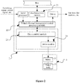
- the drive control module 23 includes a coil sample-and-hold circuit 231, an ADC circuit 232 and a logic processing register 233.
- the motor 31 includes a coil a and a coil b.
- the coil sample-and-hold circuit 231 alternately selects one of the coils a and b as a current voltage sampling source, that is, the coil a is selected as the current voltage sampling source when starting sampling, and the coil b is selected as the current voltage sampling source for the next time, such that the sampling is performed alternately, and the voltage across two ends of the selected coil is sampled and output by the coil sample-and-hold circuit to the ADC circuit 232.
- the ADC circuit 232 converts an analog signal into the digital signal and outputs the digital signal to the logic processing register 233.
- the logic processing register 233 includes a bemf register 234 configured to store the digital signal sent by the ADC circuit 232, and the digital signal converted by the ADC circuit 232 is updated accordingly in the bemf register 234.
- the logic processing register 233 according to an inputted reference clock, controls the generation of a drive signal and sends the drive signal to the drive module.
- the logic processing register 233 may provide a clock signal to the coil sample-and-hold circuit 231, to enable that voltage sampling of the coil is performed only during a period in which no voltage is applied to any phase coil of the motor.
- the logic processing register 233 further includes a micro-step register 235.
- a value stored in the micro-step register 235 is a micro-step value corresponding to the current running position of the motor. Therefore, by reading the value stored in the micro-step register, it can be determined at which micro-step position the motor is running currently.
- a value range of the register may range from 0 to 63, and the range corresponds to 4 full steps, that is, one drive cycle. When the set value for the stepping mode is changed, the range of the register may be changed accordingly.
- the drive control module 23 samples the voltage of the phase coil to which no voltage is applied during the period in which no voltage is applied to any phase coil of the motor, and converts the voltage of the phase coil into the digital signal, and stores the digital signal. During this period, the drive control module 23 samples the voltage of the coil multiple times. The number of times the voltage is sampled depends on a motor speed and a sampling frequency. Generally, the higher the motor speed and the greater the sampling frequency, the more the number of times the coil voltage is sampled, and each sample value of the coil voltage is updated to the bemf register 234 in real time.
- a first time period T a0 (corresponding to a micro-step value of 0) and a second time period T b0 (corresponding to a micro-step value of 16) in Figure 6 respectively correspond to two periods in which no voltage is applied to the a-phase coil and the b-phase coil. Sampling the coil voltage occurs in these periods, such that the micro-step value of 0, that is, a last sampled voltage value in the first time period T a0 , is stored in the bemf register 234 until the second time period T b0 .
- the first time period T a0 corresponds to a period between a first time point T 1 and a second time point T 2 shown in Figure 4 .
- the drive control module 23 continuously samples the coil voltage between the first time point T 1 and the second time point T 2 , and updates the sample value stored in the bemf register 234.
- the first sampling is S10 and the last sampling is S27.
- the number of times the voltage is sampled is 18, and each sample value is updated and stored in the bemf register 234.
- the bemf register stores the last sample value until a starting point of the second period T b0 .
- the bemf register 234 always stores the last sample value during a period from an ending point of the first time period T a0 to the starting point of the second time period T b0 .
- the first sampling S10 to the 18th sampling S27 occur in the first time period T a0 , and the time period corresponds to the same micro-step value stored in the micro-step register 235.
- the corresponding value range of the micro-step register 235 may range from 0 to 63, and this range corresponds to 4 full steps, that is, one drive cycle.
- the micro-step values are 0, 16, 32, and 48, respectively. When the micro-step value is 0, the micro-step value corresponds to the time period between the first time point T 1 and the second time point T 2 shown in Figure 4 .
- the first time point T 1 is a moment when the voltage is stopped from being applied to the coil, the current of the coil does not immediately become zero, and there is always a problem that the coil voltage between the first time point T 1 and a delay time point T decay is not an actual back electromotive force of the coil.
- a delay module 236 may be integrated in the logic processing register 233, such that the central processing module 22 reads the digital signal bemf i from the drive control module 23 after the delay time point T decay , to allow the sampled coil voltage to more approximate to the actual back electromotive force, thereby further improving the reliability of control.
- control method is used for controlling the operating state of the motor.
- the control method is implemented by the above control system of the motor, and includes the following steps a1 to a6.
- Step a1 a preset threshold bemf thr is read.
- Step a3 the digital signal bemf; is converted into a conversion value EQUIbemf i by the central processing module, where an absolute value of a first conversion value corresponding to a digital signal with a high abnormality probability is greater than an absolute value of a second conversion value corresponding to a digital signal with a low stalling probability, and a type of the preset threshold bemf thr is the same as a type of the conversion value EQUIbemf i .
- Step a5 it is determined whether an absolute value of the accumulated value bemftotal i is greater than that of the preset threshold bemf thr , if yes, Step a6 is performed, otherwise Step a2 is performed.
- Step a6 the central processing module determines that the motor is in an abnormal operation state and generates an abnormal signal.
- the operating state of the motor includes the abnormal operation, and the abnormal operation includes a stalling state.
- the control method further increases the reliability of control by converting the digital signal to the conversion value corresponding to the abnormal operation probability, accumulating the conversion values, and comparing the accumulated value with the preset threshold.
- the abnormality probability includes a stalling probability.
- the preset threshold may be a positive number or a negative number. If the preset threshold is a positive number, the first conversion value is a positive number. In the normal operating state, the conversion value corresponding to the digital signal at least includes a negative number.
- the accumulated value has a minimum value, and when the accumulated value is less than the minimum value, the minimum value is assigned to the accumulated value, and when the accumulated value is greater than the preset threshold, it is determined that the operating state of the motor is the abnormal operation, and it is further determined that the motor is stalled.
- the first conversion value corresponding to the digital signal with a high abnormality probability is a negative number.
- the conversion value corresponding to the digital signal at least includes a positive number.
- the accumulated value has a maximum value, and when the accumulated value is greater than the maximum value, the maximum value is assigned to the accumulated value, and when the accumulated value is less than the preset threshold, it is determined that the operating state of the motor is the abnormal operation, and it is further determined that the motor is stalled.
- Figure 8 is a flow chart of a second embodiment of the control method.
- the control method of the motor is used for controlling the operating state of the motor.
- the control method is implemented by the above control system of the motor, and includes the following steps a1 to a6.
- Step a1 an initial value bemftotalo of the accumulated value bemftotal i is preset and a preset threshold bemf thr is read.
- Step a5 it is determined whether the accumulated value bemftotal i is greater than the preset threshold bemf thr , if yes, Step a6 is performed, otherwise Step a2 is performed.
- Step a6 the central processing module determines that the motor is in an abnormal operation state and generates an abnormal signal.
- the initial value of the accumulated value in this embodiment is preset according to the motor speed and the motor properties, which further improves the reliability of the control system.
- Figure 9 is a flow chart of a third embodiment of the control method.
- the control method of the motor is used for controlling the operating state of the motor.
- the control method is implemented by the above control system of the motor, and includes the following steps a1 to a6.
- Step a1 an initial value bemftotal 0 of an accumulated value bemftotal i is preset and a preset threshold bemf thr is read.
- Step b3 it is determined whether a moment when the central processing module reads the digital signal belongs to a period in which no voltage is applied to any phase coil of the motor, and if yes, Step a2 is performed, otherwise Step a3 is performed.
- Step a5 it is determined whether the accumulated value bemftotal i is greater than the preset threshold bemf thr , if yes, Step a6 is performed, otherwise Step a2 is performed.
- Step a6 the central processing module determines that the motor is in an abnormal operation state and generates an abnormal signal.
- the time for the central processing module reading the digital signal bemf i is set to be after the second time period T b0 , which avoids a situation that the sampled voltage value of the coil is greater than the back electromotive force value, thereby further improving the reliability of the control system.
- Figure 10 is a flow chart of a fourth embodiment of the control method.
- the control method of the motor is used for controlling the operating state of the motor.
- the control method is implemented by the above control system of the motor, and includes the following steps a1 to a6.
- Step a1 an initial value bemftotal 0 of an accumulated value bemftotal i is preset and a preset threshold bemf thr is read.
- Step b3 it is determined whether a moment when the central processing module reads the digital signal belongs to a period in which no voltage is applied to any phase coil of the motor, and if yes, Step a2 is performed, otherwise Step b31 is performed.
- Step b31 it is determined whether there is one time period, in which no voltage is applied to any phase coil of the motor, included between two adjacent read digital signals, and if yes, Step a3 is performed, and otherwise Step a2 is performed.
- Step a5 it is determined by the central processing module whether the accumulated value bemftotal i is greater than the preset threshold bemf thr , if yes, Step a6 is performed, otherwise Step a2 is performed.
- Step a6 the central processing module determines that the motor is in an abnormal operation state and generates an abnormal signal.
- Step b31 is added in this embodiment, such that between the first time period T a0 and the second time period T b0 , the value of the digital signal bemf i is read only once and then calculated, which can improve the efficiency of control.
- Step b31 may be the following step or the following step may be provided after the step b31: it is determined whether the digital signal is read once between two adjacent periods in which no voltage is applied to any phase coil of the motor, and if yes, Step a3 is performed, otherwise Step a2 is performed, which is advantageous for preventing the signal from jumping and improving the accuracy of control.
- the control method further includes Step b2 after or before Step a1.
- Step b2 the motor speed is controlled to avoid resonance intervals of the motor, where the speed corresponding to the resonance intervals of the motor is related to properties of the motor itself, and Step b2 is not shown in the specific embodiment.
Landscapes
- Engineering & Computer Science (AREA)
- Power Engineering (AREA)
- Physics & Mathematics (AREA)
- General Physics & Mathematics (AREA)
- Mechanical Engineering (AREA)
- Thermal Sciences (AREA)
- General Engineering & Computer Science (AREA)
- Control Of Electric Motors In General (AREA)
- Control Of Stepping Motors (AREA)
Abstract
Description
- The present application claims the priority to Chinese Patent Application No.
2017103717240 - The present application relates to the field of control technology, and in particular to a control system and a control method.
- In the conventional technology, a controller determines a theoretical position according to a back electromotive force of a motor coil, and then sends a drive signal to a motor according to the theoretical position to control the operation of the motor. However, during the operation of the motor, there is a situation where the theoretical position of the motor determined according to the back electromotive force does not match an actual position of the motor when the motor is stuck or stalled, while the controller still sends the drive signal to the motor according to the theoretical position, so that the motor cannot run to a target position according to the requirements of the controller, resulting in unreliable control.
- Therefore, there is a need to improve the conventional technology to solve the above technical issues.
- An object of the present application is to provide a control system and a control method, which are advantageous for improving the reliability of the control.
- In order to achieve the above object, a control system is provided according to the present application. The control system is capable of controlling a motor and includes a central processing module and a drive control module;
- when the motor is running, the drive control module is configured to sample a voltage of a phase coil of the motor, to which no voltage is applied, during a period in which no voltage is applied to any phase coil of the motor, and convert the sampled voltage of the phase coil of the motor, to which no voltage is applied, into a digital signal;
- the control system is configured to store the digital signal, and update the digital signal in real time during the period in which no voltage is applied to any phase coil of the motor;
- the central processing module is configured read the digital signal, and the control system is configured to convert the digital signal into a conversion value according to an abnormality probability of the motor running abnormally; and
- the central processing module is configured to sequentially accumulate the conversion values to obtain an accumulated value, and determine an operating state of the motor according to a relationship between the accumulated value and a preset threshold.
- Optionally, the control system being configured to convert the digital signal into a conversion value according to an abnormality probability of the motor running abnormally is implemented as follows: the control system is configured to convert the digital signal into a first conversion value when the abnormality probability of the motor is higher than a preset probability threshold; and
convert the digital signal into a second conversion value when the abnormality probability of the motor is lower than the preset probability threshold, wherein an absolute value of the first conversion value is greater than an absolute value of the second conversion value. - Optionally, the preset threshold is a positive number, and the first conversion value is a positive number; if the motor is in a normal operating state, the conversion value corresponding to the digital signal at least includes a negative number; and
the accumulated value has a minimum value, and when the accumulated value is less than the minimum value, the minimum value is assigned to the accumulated value; and when the accumulated value is greater than the preset threshold, it is determined that the operating state of the motor is an abnormal operation. - Optionally, the preset threshold is a negative number, and the first conversion value is a negative number; if the motor is in the normal operating state, the conversion value corresponding to the digital signal at least includes a positive number; and
the accumulated value has a maximum value, and when the accumulated value is greater than the maximum value, the maximum value is assigned to the accumulated value; and when the accumulated value is less than the preset threshold, it is determined that the operating state of the motor is the abnormal operation. - Optionally, the central processing module is further configured to set an initial value for the accumulated value, a type of the initial value is the same as a type of the preset threshold, and the accumulated value is equal to a sum of a previous accumulated value and the conversion value obtained by converting a current digital signal, wherein the first accumulated value is equal to the sum of the initial value and the conversion value converted from the digital signal read for the first time.
- Optionally, one full step of motor operation includes at least two micro-steps and the drive control module further includes a micro-step register; and
the micro-step register is configured to store a current micro-step value of the motor, and the period in which no voltage is applied to any phase coil of the motor corresponds to a same micro-step value, and a moment when the central processing module reads the digital signal does not belong to the period in which no voltage is applied to any phase coil of the motor. - Optionally, one period, in which no voltage is applied to any phase coil of the motor, is included between the two adjacent moments when the central processing module reads the digital signal.
- Optionally, the central processing module at least reads the digital signal once between the two adjacent periods in which no voltage is applied to any phase coil of the motor.
- Optionally, the abnormal operation includes motor stalling; and
the central processing module is further configured to control a speed of the motor to avoid a speed corresponding to one or more resonance intervals of the motor, and the speed corresponding to the resonance intervals of the motor is related to properties of the motor itself. - The present application also discloses a control method for controlling a motor, the motor is controlled by the control system, and the control system includes a central processing module and a drive control module;
when the motor is running, the drive control module is configured to sample a voltage of a phase coil of the motor, to which no voltage is applied, during a period in which no voltage is applied to any phase coil of the motor, and convert the voltage of the phase coil of the motor, to which no voltage is applied, into a digital signal;
the control system is configured to store the digital signal, and update the digital signal in real time during the period in which no voltage is applied to any phase coil of the motor;
the central processing module is configured to read the digital signal and perform the control method, and the control method includes the following steps: - a1, reading a preset threshold bemfthr;
- a2, reading a digital signal bemfi, wherein i represents the number of times the digital signal is read, and i=1, 2...;
- a3, converting, according to an abnormality probability, the digital signal bemfi into a corresponding conversion value EQUIbemfi, wherein i represents the number of times the digital signal is read, and i=1, 2...;
- a4, calculating an accumulated value bemftotali according to an equation bemftotali=bemftotali-1+EQUIbemfi, wherein i represents the number of times the digital signal is read, i=1, 2..., bemftotali-1 is a previous accumulated value, and when i=1, the accumulated value bemftotal0=0;
- a5, comparing the accumulated value bemftotali with the preset threshold bemfthr; and a6, determining whether an absolute value of the accumulated value bemftotali is greater than an absolute value of the preset threshold bemfthr, and if yes, determining an operating state of the motor, and otherwise proceeding to Step a2.
- The present application further discloses another control method for controlling a motor, the motor is controlled by the control system, and the control system includes the central processing module and the drive control module;
when the motor is running, the drive control module is configured to sample a voltage of a phase coil of the motor, to which no voltage is applied, during a period in which no voltage is applied to any phase coil of the motor, and convert the voltage of the phase coil of the motor, to which no voltage is applied, into a digital signal;
the control system is configured to store the digital signal, and update the digital signal in real time during the period in which no voltage is applied to any phase coil of the motor;
the central processing module is configured to read the digital signal and perform the control method, and the control method includes the following steps: - a1, reading a preset threshold bemfthr and setting an initial value bemftotal0;
- a2, reading a digital signal bemfi, wherein i represents the number of times the digital signal is read, and i=1, 2...;
- a3, converting, according to an abnormality probability, the digital signal bemfi into a corresponding conversion value EQUIbemfi, wherein i represents the number of times the digital signal is read, and i=1, 2...;
- a4, calculating an accumulated value bemftotali according to an equation bemftotali=bemftotali-1+EQUIbemfi, wherein i represents the number of times the digital signal is read, i=1, 2..., bemftotali-1 is a previous accumulated value, and when i=1, the accumulated value bemftotal1=bemftotal0+EQUIbemf1;
- a5, comparing the accumulated value bemftotali with the preset threshold bemfthr; and
- a6, determining whether an absolute value of the accumulated value bemftotali is greater than an absolute value of the preset threshold bemfthr by the central processing module, and if yes, determining an operating state of the motor, and otherwise proceeding to Step a2.
- Optionally, the control method further includes:
determining the motor is in an abnormal operation state and generating an abnormal signal by the central processing module when the absolute value of the accumulated value bemftotali is greater than that of the preset threshold bemfthr. - Optionally, the control method further includes Step b3 between Step a2 and Step a3;
Step b3, determining whether a moment, when the central processing module reads the digital signal, belongs to the period in which no voltage is applied to any phase coil of the motor, and if yes, proceeding to Step a2, and otherwise proceeding to Step a3. - Optionally, the control method further includes Step b31 after Step b3;
Step b31, determining whether there is one period, in which no voltage is applied to any phase coil of the rotor, between two adjacent moments when the digital signal is read, and if yes proceeding to Step a3, and otherwise proceeding to Step a2. - Optionally, the control method further includes Step b31 after Step b3.
- Step b31, determining whether the digital signal is read once between two adjacent periods in which no voltage is applied to any phase coil of the motor, and if yes, proceeding to Step a3, and otherwise proceeding to Step a2.
- Optionally, the abnormal operation includes motor stalling, and the control method further includes Step b2 after or before Step a1;
Step b2, controlling a speed of the motor to avoid resonance intervals of the motor, wherein a speed corresponding to the resonance intervals of the motor is related to properties of the motor itself. - Compared with the conventional technology, in the control system provided by the present application, the drive control module samples the voltage of the phase coil, to which no voltage is applied, when there is no voltage is applied to any phase coil of the motor, and converts the voltage of the phase coil into the digital signal, and stores the digital signal. The central processing module reads the digital signal and converts the digital signal to obtain the conversion value, and sequentially accumulates the conversion values to obtain the accumulated value, and determines the operating state of the motor according to the relationship between the accumulated value and the preset threshold. The central processing module converts the digital signal to obtain the conversion value based on the magnitude of the abnormality probability, and accumulates the conversion values to determine the operating state of the motor. Since some accumulated values may counteract each other, which is advantageous for eliminating occasional misjudgment, the reliability of determining the operating state of the motor may be improved.
-
-
Figure 1 is a schematic functional diagram of a first embodiment of a control system according to the present application; -
Figure 2 is a schematic functional diagram of a second embodiment of the control system according to the present application; -
Figure 3 is a schematic diagram of an embodiment of a drive control module shown inFigure 1 orFigure 2 ; -
Figure 4 is a schematic diagram showing the correspondence relationship between the current of a phase coil to which no voltage is applied and the time; -
Figure 5 is a schematic diagram showing the correspondence relationship between the voltage of a phase coil to which no voltage is applied and the time; -
Figure 6 is a schematic diagram showing the correspondence relationship between the currents of the a-phase coil and the b-phase coil of the motor and the time; -
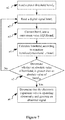
Figure 7 is a schematic flow chart of a first embodiment of a control method according to the present application; -
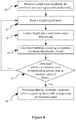
Figure 8 is a schematic flow chart of a second embodiment of the control method according to the present application; -
Figure 9 is a schematic flow chart of a third embodiment of the control method according to the present application; and -
Figure 10 is a schematic flow chart of a fourth embodiment of the control method according to the present application. - The present application will be further described below in conjunction with the accompanying drawings and specific embodiments.
- An electronic expansion valve is applicable to an air conditioning system. The air conditioning system further includes a compressor, a condenser and an evaporator, and the electronic expansion valve is configured to control a flow rate of a refrigerant from the condenser to the evaporator. The electronic expansion valve moves according to the requirements of the control system. The electronic expansion valve includes a motor and a valve body. The stepping motor includes a coil and a rotor. The control system includes a central processing module and a drive control module, and the central processing module sends a control signal based on an operating state of the motor to control the action of the stepping motor. The central processing module may be integrated into a controller of the air conditioning system or may be a controller integrated in a superior computer of the air conditioning system, such as a controller of a vehicle. In this embodiment, the drive control module samples a voltage of one phase coil with no voltage being applied when no voltage is applied to any phase coil of the motor, and converts the voltage of this phase coil into a digital signal and stores the digital signal. The central processing module reads the digital signal and converts the digital signal to obtain a conversion value, and sequentially accumulates the conversion values to obtain an accumulated value. The central processing module determines the operating state of the motor according to a relationship between the accumulated value and a preset threshold. In this way, the central processing module converts the digital signal to obtain the conversion value according to the magnitude of the abnormality probability, and accumulates the conversion values to determine the operating state of the motor, such that some accumulated values may counteract each other, which is advantageous for eliminating occasional misjudgment and for improving the reliability of determining the operating state of the motor.
- In this embodiment, the operating state of the motor includes an abnormal operation and a normal operation. The abnormal operation of the motor includes motor stalling, motor running at abnormal speed and the like. This embodiment is described by taking motor stalling as an example.
- In addition, the motor in this embodiment may be applied to a domestic air conditioning system, and may be applied to a vehicle air conditioning system. The motor in the present application may be applied to an electronic expansion valve, an electronic water valve and other products driven by a motor. A detailed description is given hereinafter with the motor, the control system and the control method being applied to the electronic expansion valve. This embodiment is described in conjunction with the control system and control method applied to the vehicle air conditioning system.
- The control system in this embodiment is described below with reference to
Figure 1 ,Figure 2 andFigure 3 , respectively. - Referring to
Figure 1 , in this embodiment, thecontrol system 2 includes abus transceiver module 21, acentral processing module 22, adrive control module 23 and adrive module 24. Theelectronic expansion valve 3 includes amotor 31 and avalve body 32. Themotor 31 is a stepping motor. Thecontrol system 2 can control the operation of themotor 31. Thecontrol system 2 is connected with abus 1 and themotor 31. Thebus transceiver module 21 is configured to receive a control signal sent by thebus 1 and send the control signal to thecentral processing module 22. Thecentral processing module 22 performs a method calculation after reading a digital signal from thedrive control module 23 and determines an operating state of the steppingmotor 31. Thedrive control module 23 samples a voltage of a phase coil to which no voltage is applied when no voltage is applied to any phase coil of the motor, and converts the voltage of this phase coil into a digital signal and stores the digital signal. Thedrive module 24 is configured to receive a control signal sent by thedrive control module 23, and control on and off of the current supply of the steppingmotor 31. The abovebus transceiver module 21 may be a LIN transceiver module or other communication module such as a CAN transceiver module or a PWM communication module. - Referring to
Figure 2 , in this embodiment, thecontrol system 2 includes abus transceiver module 21, a central processing module, adrive control module 23 and adrive module 24. Compared with the first embodiment, the central processing module is integrated into a vehicle thermal managementcentral processing module 22. In addition to sending a control signal to thedrive control module 23, the vehicle thermal managementcentral processing module 22 also sends control signals to other devices of the vehicle. With such arrangement of the central processing module, the space is saved and the connection of the control system is simplified. Thebus transceiver module 21 is configured to receive a control signal sent by a LIN bus or/and aCAN bus 1 and send the control signal to the vehicle thermal managementcentral processing module 22, where thebus transceiver module 21 may also be other communication module, such as a PWM communication module. - Referring to
Figure 3 , in this embodiment, thedrive control module 23 includes a coil sample-and-hold circuit 231, anADC circuit 232 and alogic processing register 233. Assuming that, themotor 31 includes a coil a and a coil b. The coil sample-and-hold circuit 231 alternately selects one of the coils a and b as a current voltage sampling source, that is, the coil a is selected as the current voltage sampling source when starting sampling, and the coil b is selected as the current voltage sampling source for the next time, such that the sampling is performed alternately, and the voltage across two ends of the selected coil is sampled and output by the coil sample-and-hold circuit to theADC circuit 232. TheADC circuit 232 converts an analog signal into the digital signal and outputs the digital signal to thelogic processing register 233. Thelogic processing register 233 includes abemf register 234 configured to store the digital signal sent by theADC circuit 232, and the digital signal converted by theADC circuit 232 is updated accordingly in thebemf register 234. Thelogic processing register 233, according to an inputted reference clock, controls the generation of a drive signal and sends the drive signal to the drive module. Thelogic processing register 233 may provide a clock signal to the coil sample-and-hold circuit 231, to enable that voltage sampling of the coil is performed only during a period in which no voltage is applied to any phase coil of the motor. - The
logic processing register 233 further includes amicro-step register 235. A value stored in themicro-step register 235 is a micro-step value corresponding to the current running position of the motor. Therefore, by reading the value stored in the micro-step register, it can be determined at which micro-step position the motor is running currently. In a case that a set value for a motor stepping mode is 16 micro-steps (that is, a full step is divided into 16 micro-steps), a value range of the register may range from 0 to 63, and the range corresponds to 4 full steps, that is, one drive cycle. When the set value for the stepping mode is changed, the range of the register may be changed accordingly. - The
drive control module 23 samples the voltage of the phase coil to which no voltage is applied during the period in which no voltage is applied to any phase coil of the motor, and converts the voltage of the phase coil into the digital signal, and stores the digital signal. During this period, thedrive control module 23 samples the voltage of the coil multiple times. The number of times the voltage is sampled depends on a motor speed and a sampling frequency. Generally, the higher the motor speed and the greater the sampling frequency, the more the number of times the coil voltage is sampled, and each sample value of the coil voltage is updated to thebemf register 234 in real time. - The above sampling process is described below with reference to
Figure 4, Figure 5 and Figure 6 . - Referring to
Figure 6 , a first time period Ta0 (corresponding to a micro-step value of 0) and a second time period Tb0 (corresponding to a micro-step value of 16) inFigure 6 respectively correspond to two periods in which no voltage is applied to the a-phase coil and the b-phase coil. Sampling the coil voltage occurs in these periods, such that the micro-step value of 0, that is, a last sampled voltage value in the first time period Ta0, is stored in thebemf register 234 until the second time period Tb0. The first time period Ta0 corresponds to a period between a first time point T1 and a second time point T2 shown inFigure 4 . Thedrive control module 23 continuously samples the coil voltage between the first time point T1 and the second time point T2, and updates the sample value stored in thebemf register 234. As shown inFigure 5 , in this embodiment, according to the speed of the motor, the first sampling is S10 and the last sampling is S27. The number of times the voltage is sampled is 18, and each sample value is updated and stored in thebemf register 234. After the second time point T2, the bemf register stores the last sample value until a starting point of the second period Tb0. As shown inFigure 6 , during a period from an ending point of the first time period Ta0 to the starting point of the second time period Tb0, thebemf register 234 always stores the last sample value. - As shown in
Figure 5 , the first sampling S10 to the 18th sampling S27 occur in the first time period Ta0, and the time period corresponds to the same micro-step value stored in themicro-step register 235. If the set value for the motor stepping mode is 16 micro-steps, the corresponding value range of themicro-step register 235 may range from 0 to 63, and this range corresponds to 4 full steps, that is, one drive cycle. The micro-step values are 0, 16, 32, and 48, respectively. When the micro-step value is 0, the micro-step value corresponds to the time period between the first time point T1 and the second time point T2 shown inFigure 4 . - Referring to
Figure 4 , the first time point T1 is a moment when the voltage is stopped from being applied to the coil, the current of the coil does not immediately become zero, and there is always a problem that the coil voltage between the first time point T1 and a delay time point Tdecay is not an actual back electromotive force of the coil. Thus, adelay module 236 may be integrated in thelogic processing register 233, such that thecentral processing module 22 reads the digital signal bemfi from thedrive control module 23 after the delay time point Tdecay, to allow the sampled coil voltage to more approximate to the actual back electromotive force, thereby further improving the reliability of control. - The control method of the embodiments of the present application is described below with reference to
Figs. 7-10 . - Referring to
Figure 7 , in this embodiment, the control method is used for controlling the operating state of the motor. The control method is implemented by the above control system of the motor, and includes the following steps a1 to a6. - In Step a1, a preset threshold bemfthr is read.
- In Step a2, a digital signal bemfi is read, where i represents the number of times the digital signal is read, i = 1, 2....
- In Step a3, the digital signal bemf; is converted into a conversion value EQUIbemfi by the central processing module, where an absolute value of a first conversion value corresponding to a digital signal with a high abnormality probability is greater than an absolute value of a second conversion value corresponding to a digital signal with a low stalling probability, and a type of the preset threshold bemfthr is the same as a type of the conversion value EQUIbemfi.
- In Step a4, an accumulated value bemftotali is calculated according to the equation bemftotali=bemftotali-1+EQUIbemfi, where i represents the number of times the digital signal is read, i=1, 2..., bemftotali-1 represents a previous accumulated value; and when i=1, the accumulated value bemftotal1=bemftotal0+EQUIbemf1, where the bemftotal0=0.
- In Step a5, it is determined whether an absolute value of the accumulated value bemftotali is greater than that of the preset threshold bemfthr, if yes, Step a6 is performed, otherwise Step a2 is performed.
- In Step a6, the central processing module determines that the motor is in an abnormal operation state and generates an abnormal signal.
- The operating state of the motor includes the abnormal operation, and the abnormal operation includes a stalling state.
- The control method further increases the reliability of control by converting the digital signal to the conversion value corresponding to the abnormal operation probability, accumulating the conversion values, and comparing the accumulated value with the preset threshold.
- In this embodiment, the abnormality probability includes a stalling probability. The preset threshold may be a positive number or a negative number. If the preset threshold is a positive number, the first conversion value is a positive number. In the normal operating state, the conversion value corresponding to the digital signal at least includes a negative number. The accumulated value has a minimum value, and when the accumulated value is less than the minimum value, the minimum value is assigned to the accumulated value, and when the accumulated value is greater than the preset threshold, it is determined that the operating state of the motor is the abnormal operation, and it is further determined that the motor is stalled.
- If the preset threshold is a negative number, the first conversion value corresponding to the digital signal with a high abnormality probability is a negative number. In the normal operating state, the conversion value corresponding to the digital signal at least includes a positive number. The accumulated value has a maximum value, and when the accumulated value is greater than the maximum value, the maximum value is assigned to the accumulated value, and when the accumulated value is less than the preset threshold, it is determined that the operating state of the motor is the abnormal operation, and it is further determined that the motor is stalled.
-
Figure 8 is a flow chart of a second embodiment of the control method. In this embodiment, the control method of the motor is used for controlling the operating state of the motor. The control method is implemented by the above control system of the motor, and includes the following steps a1 to a6. - In Step a1, an initial value bemftotalo of the accumulated value bemftotali is preset and a preset threshold bemfthr is read.
- In Step a2, a digital signal bemfi is read, where i represents the number of times the digital signal is read, i = 1, 2....
- In Step a3, a digital signal bemfi is converted into a conversion value EQUIbemfi, where an absolute value of a first conversion value corresponding to a digital signal with a high abnormality probability is greater than an absolute value of a second conversion value corresponding to a digital signal with a low stalling probability, a type of the preset initial value bemftotal0 of the accumulated value bemftotali is the same as a type of the conversion value EQUIbemfi, and a type of the preset threshold bemfthr is the same as the type of the conversion value EQUIbemfi, and the central processing module calculates the accumulated value bemftotali according to the equation bemftotali= bemftotali-1+EQUIbemfi, where i represents the number of times the digital signal is read, i = 1, 2....
- In Step a4, an accumulated value bemftotali is calculated according to the equation bemftotali=bemftotali-1+EQUIbemfi, where i=1, 2..., and bemftotali-1 represents a previous accumulated value, and when i=1, the accumulated value bemftotal1=bemftotal0+EQUIbemf1, the bemftotalo is the initial value; the current accumulated value equals to the sum of the previous accumulated value and the current digital signal, and the first accumulated value equals to the sum of the initial value and the first read digital signal.
- In Step a5, it is determined whether the accumulated value bemftotali is greater than the preset threshold bemfthr, if yes, Step a6 is performed, otherwise Step a2 is performed.
- In Step a6, the central processing module determines that the motor is in an abnormal operation state and generates an abnormal signal.
- Compared with the first embodiment, the initial value of the accumulated value in this embodiment is preset according to the motor speed and the motor properties, which further improves the reliability of the control system.
-
Figure 9 is a flow chart of a third embodiment of the control method. In this embodiment, the control method of the motor is used for controlling the operating state of the motor. The control method is implemented by the above control system of the motor, and includes the following steps a1 to a6. - In Step a1, an initial value bemftotal0 of an accumulated value bemftotali is preset and a preset threshold bemfthr is read.
- In Step a2, a digital signal bemfi is read by the central processing module, where i represents the number of times the digital signal is read, and i = 1, 2....
- In Step b3, it is determined whether a moment when the central processing module reads the digital signal belongs to a period in which no voltage is applied to any phase coil of the motor, and if yes, Step a2 is performed, otherwise Step a3 is performed.
- In Step a3, the digital signal bemfi is converted into a conversion value EQUIbemfi, where an absolute value of a first conversion value corresponding to a digital signal with a high abnormality probability is greater than an absolute value of a second conversion value corresponding to a digital signal with a low stalling probability, a type of the preset initial value bemftotalo of the accumulated value bemftotali is the same as a type of the conversion value EQUIbemfi, and a type of the preset threshold bemfthr is the same as a type of the conversion value EQUIbemfi; and the accumulated value bemftotali is calculated according to the equation bemftotali= bemftotali-1+EQUIbemfi, where i represents the number of times the digital signal is read, and i = 1, 2....
- In Step a4, the accumulated value bemftotali is calculated according to the equation bemftotali=bemftotali-1+EQUIbemfi, where i represents the number of times the digital signal is read, and i=1, 2...
- In Step a5, it is determined whether the accumulated value bemftotali is greater than the preset threshold bemfthr, if yes, Step a6 is performed, otherwise Step a2 is performed.
- In Step a6, the central processing module determines that the motor is in an abnormal operation state and generates an abnormal signal.
- Compared with the second embodiment, in this embodiment, it is determined whether the moment when the central processing module reads the digital signal belongs to the period in which no voltage is applied to any phase coil of the motor, then the time for the central processing module reading the digital signal bemfi is set to be after the second time period Tb0, which avoids a situation that the sampled voltage value of the coil is greater than the back electromotive force value, thereby further improving the reliability of the control system.
-
Figure 10 is a flow chart of a fourth embodiment of the control method. In this embodiment, the control method of the motor is used for controlling the operating state of the motor. The control method is implemented by the above control system of the motor, and includes the following steps a1 to a6. - In Step a1, an initial value bemftotal0 of an accumulated value bemftotali is preset and a preset threshold bemfthr is read.
- In Step a2, a digital signal bemfi is read, where i represents the number of times the digital signal is read, and i = 1, 2....
- In Step b3, it is determined whether a moment when the central processing module reads the digital signal belongs to a period in which no voltage is applied to any phase coil of the motor, and if yes, Step a2 is performed, otherwise Step b31 is performed.
- In Step b31, it is determined whether there is one time period, in which no voltage is applied to any phase coil of the motor, included between two adjacent read digital signals, and if yes, Step a3 is performed, and otherwise Step a2 is performed.
- In Step a3, the digital signal bemfi is converted into a conversion value EQUIbemfi, where an absolute value of a first conversion value corresponding to a digital signal with a high abnormality probability is greater than an absolute value of a second conversion value corresponding to a digital signal with a low stalling probability, a type of the initial value bemftotal0 of the accumulated value bemftotali is the same as a type of the conversion value EQUIbemfi, and a type of the preset threshold bemfthr is the same as a type of the conversion value EQUIbemfi; and the accumulated value bemftotali is calculated according to the equation bemftotali= bemftotali-1+EQUIbemfi, where i represents the number of times the digital signal is read, and i = 1, 2....
- In Step a4, the accumulated value bemftotali is calculated by the central processing module according to the equation bemftotali=bemftotali-1+EQUIbemfi, where i represents the number of times the digital signal is read, and i=1, 2...
- In Step a5, it is determined by the central processing module whether the accumulated value bemftotali is greater than the preset threshold bemfthr, if yes, Step a6 is performed, otherwise Step a2 is performed.
- In Step a6, the central processing module determines that the motor is in an abnormal operation state and generates an abnormal signal.
- Compared with the third embodiment, Step b31 is added in this embodiment, such that between the first time period Ta0 and the second time period Tb0, the value of the digital signal bemfi is read only once and then calculated, which can improve the efficiency of control.
- Apparently, Step b31 may be the following step or the following step may be provided after the step b31: it is determined whether the digital signal is read once between two adjacent periods in which no voltage is applied to any phase coil of the motor, and if yes, Step a3 is performed, otherwise Step a2 is performed, which is advantageous for preventing the signal from jumping and improving the accuracy of control.
- The control method further includes Step b2 after or before Step a1. In Step b2, the motor speed is controlled to avoid resonance intervals of the motor, where the speed corresponding to the resonance intervals of the motor is related to properties of the motor itself, and Step b2 is not shown in the specific embodiment.
- It should be noted that the above embodiments are only for explaining the present application and are not intended to limit the technical solutions described in the present application. Although the present application has been described in detail with reference to the above embodiments, those skilled in the art should understand that modification or equivalently replacement may be made to the present application by those skilled in the art, and all the technical solutions and improvements thereof without departing from the spirit and scope of the present application fall within the scope of the claims.
Claims (16)
- A control system, wherein, the control system is configured to control a motor, and comprises a central processing module and a drive control module;
when the motor is running, the drive control module is configured to sample a voltage of a phase coil of the motor, to which no voltage is applied, during a period in which no voltage is applied to any phase coil of the motor, and convert the sampled voltage of the phase coil of the motor, to which no voltage is applied, into a digital signal;
the control system is configured to store the digital signal, and update the digital signal in real time during the period in which no voltage is applied to any phase coil of the motor;
the central processing module is configured read the digital signal, and the control system is configured to convert the digital signal into a conversion value according to an abnormality probability of the motor running abnormally; and
the central processing module is configured to sequentially accumulate the conversion values to obtain an accumulated value, and determine an operating state of the motor according to a relationship between the accumulated value and a preset threshold. - The control system according to claim 1, wherein, the control system being configured to convert the digital signal into a conversion value according to an abnormality probability of the motor running abnormally is implemented as follows: the control system is configured to convert the digital signal into a first conversion value when the abnormality probability of the motor is higher than a preset probability threshold; and
convert the digital signal into a second conversion value when the abnormality probability of the motor is lower than the preset probability threshold, wherein an absolute value of the first conversion value is greater than an absolute value of the second conversion value. - The control system according to claim 2, wherein the preset threshold is a positive number, and the first conversion value is a positive number; if the motor is in a normal operating state, the conversion value corresponding to the digital signal at least comprises a negative number; and
the accumulated value has a minimum value, and when the accumulated value is less than the minimum value, the minimum value is assigned to the accumulated value; and when the accumulated value is greater than the preset threshold, it is determined that the operating state of the motor is an abnormal operation. - The control system according to claim 2, wherein the preset threshold is a negative number, and the first conversion value is a negative number; if the motor is in the normal operating state, the conversion value corresponding to the digital signal at least comprises a positive number; and
the accumulated value has a maximum value, and when the accumulated value is greater than the maximum value, the maximum value is assigned to the accumulated value; and when the accumulated value is less than the preset threshold, it is determined that the operating state of the motor is the abnormal operation. - The control system according to any one of claims 1 to 4, wherein the central processing module is further configured to set an initial value for the accumulated value, a type of the initial value is the same as a type of the preset threshold, and the accumulated value is equal to a sum of a previous accumulated value and the conversion value obtained by converting a current digital signal, wherein the first accumulated value is equal to the sum of the initial value and the conversion value converted from the digital signal read for the first time.
- The control system according to claim 5, wherein one full step of motor operation comprises at least two micro-steps and the drive control module further comprises a micro-step register; and
the micro-step register is configured to store a current micro-step value of the motor, and the period in which no voltage is applied to any phase coil of the motor corresponds to a same micro-step value, and a moment when the central processing module reads the digital signal does not belong to the period in which no voltage is applied to any phase coil of the motor. - The control system according to claim 6, wherein, one period, in which no voltage is applied to any phase coil of the motor, is included between the two adjacent moments when the central processing module reads the digital signal.
- The control system according to claim 6, wherein, the central processing module at least reads the digital signal once between the two adjacent periods in which no voltage is applied to any phase coil of the motor.
- The control system according to any one of claims 6 to 8, wherein the abnormal operation comprises motor stalling; and
the central processing module is further configured to control a speed of the motor to avoid a speed corresponding to one or more resonance intervals of the motor, and the speed corresponding to the resonance intervals of the motor is related to properties of the motor itself. - A control method, wherein the control method is used for controlling a motor, the motor is controlled by a control system, and the control system comprises a central processing module and a drive control module;
when the motor is running, the drive control module is configured to sample a voltage of a phase coil of the motor, to which no voltage is applied, during a period in which no voltage is applied to any phase coil of the motor, and convert the voltage of the phase coil of the motor, to which no voltage is applied, into a digital signal;
the control system is configured to store the digital signal, and update the digital signal in real time during the period in which no voltage is applied to any phase coil of the motor;
the central processing module is configured to read the digital signal and perform the control method, and the control method comprises the following steps:a1, reading a preset threshold bemfthr;a2, reading a digital signal bemfi, wherein i represents the number of times the digital signal is read, and i=1, 2...;a3, converting, according to an abnormality probability, the digital signal bemfi into a corresponding conversion value EQUIbemfi, wherein i represents the number of times the digital signal is read, and i=1, 2...;a4, calculating an accumulated value bemftotali according to an equation bemftotali=bemftotali-1+EQUIbemfi, wherein i represents the number of times the digital signal is read, i=1, 2..., bemftotali-1 is a previous accumulated value, and when i=1, the accumulated value bemftotal0=0;a5, comparing the accumulated value bemftotali with the preset threshold bemfthr; anda6, determining whether an absolute value of the accumulated value bemftotali is greater than an absolute value of the preset threshold bemfthr, and if yes, determining an operating state of the motor, and otherwise proceeding to Step a2. - A control method, wherein the control method is used for controlling a motor, the motor is controlled by a control system, and the control system comprises a central processing module and a drive control module;
when the motor is running, the drive control module is configured to sample a voltage of a phase coil of the motor, to which no voltage is applied, during a period in which no voltage is applied to any phase coil of the motor, and convert the voltage of the phase coil of the motor, to which no voltage is applied, into a digital signal;
the control system is configured to store the digital signal, and update the digital signal in real time during the period in which no voltage is applied to any phase coil of the motor;
the central processing module is configured to read the digital signal and perform the control method, and the control method comprises the following steps:a1, reading a preset threshold bemfthr and setting an initial value bemftotal0;a2, reading a digital signal bemfi, wherein i represents the number of times the digital signal is read, and i=1, 2...;a3, converting, according to an abnormality probability, the digital signal bemfi into a corresponding conversion value EQUIbemfi, wherein i represents the number of times the digital signal is read, and i=1, 2...;a4, calculating an accumulated value bemftotali according to an equation bemftotali=bemftotali-1+EQUIbemfi, wherein i represents the number of times the digital signal is read, i=1, 2..., bemftotali-i is a previous accumulated value, and when i=1, the accumulated value bemftotal1=bemftotal0+EQUIbemf1;a5, comparing the accumulated value bemftotali with the preset threshold bemfthr; anda6, determining whether an absolute value of the accumulated value bemftotali is greater than an absolute value of the preset threshold bemfthr by the central processing module, and if yes, determining an operating state of the motor, and otherwise proceeding to Step a2. - The control method according to claim 10 or 11, further comprising:
determining the motor is in an abnormal operation state and generating an abnormal signal by the central processing module when the absolute value of the accumulated value bemftotali is greater than that of the preset threshold bemfthr. - The control method according to claim 10 or 11, further comprising Step b3 between step a2 and step a3;
Step b3, determining whether a moment, when the central processing module reads the digital signal, belongs to the period in which no voltage is applied to any phase coil of the motor, and if yes, proceeding to Step a2, and otherwise proceeding to Step a3. - The control method according to claim 13, further comprising Step b31 after Step b3;
Step b31, determining whether there is one period, in which no voltage is applied to any phase coil of the rotor, between two adjacent moments when the digital signal is read, and if yes proceeding to Step a3, and otherwise proceeding to Step a2. - The control method according to claim 13, further comprising Step b31 after Step b3;
Step b31, determining whether the digital signal is read once between two adjacent periods in which no voltage is applied to any phase coil of the motor, and if yes, proceeding to Step a3, and otherwise proceeding to Step a2. - The control method according to claim 14 or 15, wherein, the abnormal operation comprises motor stalling, and the control method further comprises Step b2 after or before Step a1;
Step b2, controlling a speed of the motor to avoid resonance intervals of the motor, wherein a speed corresponding to the resonance intervals of the motor is related to properties of the motor itself.
Applications Claiming Priority (2)
| Application Number | Priority Date | Filing Date | Title |
|---|---|---|---|
| CN201710371724.0A CN108931085A (en) | 2017-05-24 | 2017-05-24 | control system and control method |
| PCT/CN2018/087274 WO2018214801A1 (en) | 2017-05-24 | 2018-05-17 | Control system and control method |
Publications (3)
| Publication Number | Publication Date |
|---|---|
| EP3633845A1 true EP3633845A1 (en) | 2020-04-08 |
| EP3633845A4 EP3633845A4 (en) | 2021-01-13 |
| EP3633845B1 EP3633845B1 (en) | 2022-08-17 |
Family
ID=64395313
Family Applications (1)
| Application Number | Title | Priority Date | Filing Date |
|---|---|---|---|
| EP18805756.6A Active EP3633845B1 (en) | 2017-05-24 | 2018-05-17 | Control system and control method |
Country Status (6)
| Country | Link |
|---|---|
| US (1) | US10951142B2 (en) |
| EP (1) | EP3633845B1 (en) |
| JP (1) | JP2020518224A (en) |
| KR (1) | KR102262315B1 (en) |
| CN (1) | CN108931085A (en) |
| WO (1) | WO2018214801A1 (en) |
Cited By (1)
| Publication number | Priority date | Publication date | Assignee | Title |
|---|---|---|---|---|
| EP3993257A1 (en) * | 2020-11-03 | 2022-05-04 | Ypsomed AG | System and method to detect drive blockage in a drug delivery device |
Families Citing this family (4)
| Publication number | Priority date | Publication date | Assignee | Title |
|---|---|---|---|---|
| CN108955005A (en) * | 2017-05-24 | 2018-12-07 | 杭州三花研究院有限公司 | control system and control method |
| CN111557636B (en) * | 2020-01-14 | 2023-08-11 | 杭州法博激光科技有限公司 | Soft mirror surgery auxiliary system |
| CN115514292B (en) * | 2022-10-21 | 2023-05-05 | 江门市力丰电机有限公司 | Servo motor rotating speed control system and method |
| KR102821841B1 (en) | 2023-03-13 | 2025-06-16 | 조금복 | Label that is easy to separate from the container and its manufacturing method |
Family Cites Families (18)
| Publication number | Priority date | Publication date | Assignee | Title |
|---|---|---|---|---|
| US3638480A (en) * | 1969-11-21 | 1972-02-01 | Bucyrus Erie Co | Dual-stator induction motor torque sensor ac dynamometer |
| FR2795886B1 (en) | 1999-06-29 | 2001-10-05 | Sonceboz Sa | STEP-BY-STEP METHOD OF AN ELECTRIC MOTOR OF THE STEP-BY-STEP POLYPHASE TYPE, THIS IN RELATION TO A REFERENCE POSITION CORRESPONDING TO A MECHANICAL STOP |
| JP3673964B2 (en) | 2000-03-29 | 2005-07-20 | 株式会社ルネサステクノロジ | Brushless motor drive control semiconductor integrated circuit and brushless motor drive control device |
| JP4665735B2 (en) | 2005-11-30 | 2011-04-06 | 株式会社日立製作所 | Synchronous motor drive system and synchronous motor drive method |
| KR20080042566A (en) | 2006-11-10 | 2008-05-15 | 주식회사 두원공조 | Driving speed control system of motor by PPM control and its control method |
| CN101098118B (en) * | 2007-06-13 | 2010-11-10 | 深圳市瑞凌实业股份有限公司 | Rotation velocity control method and circuit of DC dragging system |
| GB0713239D0 (en) | 2007-07-07 | 2007-08-15 | Trw Ltd | Electriv motor control |
| US7705555B2 (en) * | 2007-12-18 | 2010-04-27 | Freescale Semiconductor, Inc. | Method and controller for detecting a stall condition in a stepping motor during micro-stepping |
| CN201509176U (en) * | 2009-08-28 | 2010-06-16 | 比亚迪股份有限公司 | A kind of brushless motor control system and brushless motor |
| US8242732B2 (en) | 2009-12-18 | 2012-08-14 | Xylon d.o.o. | Apparatus, system and method for stepper motor stall detection |
| JP5786283B2 (en) | 2010-06-04 | 2015-09-30 | 株式会社リコー | Motor control apparatus, image forming apparatus, and motor control method |
| CN203522143U (en) * | 2013-08-27 | 2014-04-02 | 长沙市博巨兴电子科技有限公司 | Motor stalling detection circuit |
| JP5928438B2 (en) * | 2013-11-05 | 2016-06-01 | 株式会社デンソー | AC motor control device |
| JP6315235B2 (en) | 2013-12-06 | 2018-04-25 | セイコーエプソン株式会社 | Recording apparatus and setting method |
| KR101619699B1 (en) | 2015-03-30 | 2016-05-10 | 현대자동차주식회사 | Method of motor speed control for improving the performance of running resistance evaluation |
| CN105391350A (en) * | 2015-12-02 | 2016-03-09 | 江苏科技大学 | Detection device and method for phase counterelectromotive forces of permanent magnet synchronous motor (PMSM) |
| CN106253789B (en) * | 2016-10-27 | 2018-10-19 | 深圳市复兴伟业技术有限公司 | The zero passage method of sampling of single phase induction motor inverse electromotive force |
| CN108955005A (en) * | 2017-05-24 | 2018-12-07 | 杭州三花研究院有限公司 | control system and control method |
-
2017
- 2017-05-24 CN CN201710371724.0A patent/CN108931085A/en not_active Withdrawn
-
2018
- 2018-05-17 KR KR1020197030990A patent/KR102262315B1/en active Active
- 2018-05-17 US US16/604,553 patent/US10951142B2/en active Active
- 2018-05-17 WO PCT/CN2018/087274 patent/WO2018214801A1/en not_active Ceased
- 2018-05-17 EP EP18805756.6A patent/EP3633845B1/en active Active
- 2018-05-17 JP JP2019557831A patent/JP2020518224A/en active Pending
Cited By (2)
| Publication number | Priority date | Publication date | Assignee | Title |
|---|---|---|---|---|
| EP3993257A1 (en) * | 2020-11-03 | 2022-05-04 | Ypsomed AG | System and method to detect drive blockage in a drug delivery device |
| WO2022096352A1 (en) * | 2020-11-03 | 2022-05-12 | Ypsomed Ag | System and method to detect drive blockage in a drug delivery device |
Also Published As
| Publication number | Publication date |
|---|---|
| WO2018214801A1 (en) | 2018-11-29 |
| EP3633845A4 (en) | 2021-01-13 |
| JP2020518224A (en) | 2020-06-18 |
| KR20190127901A (en) | 2019-11-13 |
| CN108931085A (en) | 2018-12-04 |
| US20200161996A1 (en) | 2020-05-21 |
| EP3633845B1 (en) | 2022-08-17 |
| US10951142B2 (en) | 2021-03-16 |
| KR102262315B1 (en) | 2021-06-09 |
Similar Documents
| Publication | Publication Date | Title |
|---|---|---|
| US10951142B2 (en) | Control system and control method | |
| US11336217B2 (en) | Method for reducing noise of a switched reluctance motor based on adjusting a PWM carrier frequency | |
| EP2863537B1 (en) | Motor control device | |
| US20160221416A1 (en) | Refrigerant Circulation System | |
| US11585320B2 (en) | Method for controlling a multiphase separately excited synchronous generator in a wind turbine | |
| US20140084823A1 (en) | Motor controlling device and motor controlling method | |
| KR101376914B1 (en) | Apparatus and method for controlling motor | |
| CN107154760A (en) | A kind of high speed high torque (HT) implementation method of composite stepper motor | |
| US6667598B2 (en) | Circuit for generating three-phase PWM signal | |
| KR920007515B1 (en) | Method and apparatus for controlling the magnitude and direction of current flowing through a winding | |
| CN218679039U (en) | Analog-digital converter | |
| CN105553357B (en) | A kind of fixed duty cycle stepper motor constant current driving system and method | |
| US10998846B2 (en) | Control system and control method | |
| US6922028B2 (en) | Controller for permanent magnet motor | |
| CN107101428B (en) | The control method and control system of electric expansion valve | |
| CN111441947B (en) | Method and device for starting control of variable frequency compressor and computer storage medium | |
| CN110912475B (en) | Stepping motor driving method and system | |
| CN108955005A (en) | control system and control method | |
| CN100380801C (en) | Stepping motor driving circuit | |
| CN115801007B (en) | Analog-to-digital converter, chip and electronic equipment | |
| US20240348167A1 (en) | Direct voltage converter with synchronized dividing modules | |
| CN112805914B (en) | Starting method of permanent magnet synchronous motor and aircraft compressor | |
| CN119906303A (en) | A stepper motor control method, device and medium based on pre-tightening | |
| CN122068831A (en) | Motor controller | |
| AU2021408621A9 (en) | Parameter identification method and parameter identification device for wind turbine |
Legal Events
| Date | Code | Title | Description |
|---|---|---|---|
| STAA | Information on the status of an ep patent application or granted ep patent |
Free format text: STATUS: THE INTERNATIONAL PUBLICATION HAS BEEN MADE |
|
| PUAI | Public reference made under article 153(3) epc to a published international application that has entered the european phase |
Free format text: ORIGINAL CODE: 0009012 |
|
| STAA | Information on the status of an ep patent application or granted ep patent |
Free format text: STATUS: REQUEST FOR EXAMINATION WAS MADE |
|
| 17P | Request for examination filed |
Effective date: 20191015 |
|
| AK | Designated contracting states |
Kind code of ref document: A1 Designated state(s): AL AT BE BG CH CY CZ DE DK EE ES FI FR GB GR HR HU IE IS IT LI LT LU LV MC MK MT NL NO PL PT RO RS SE SI SK SM TR |
|
| AX | Request for extension of the european patent |
Extension state: BA ME |
|
| DAV | Request for validation of the european patent (deleted) | ||
| DAX | Request for extension of the european patent (deleted) | ||
| A4 | Supplementary search report drawn up and despatched |
Effective date: 20201215 |
|
| RIC1 | Information provided on ipc code assigned before grant |
Ipc: H02P 6/08 20160101ALN20201209BHEP Ipc: H02P 8/34 20060101ALI20201209BHEP Ipc: H02P 6/182 20160101ALN20201209BHEP Ipc: H02P 29/024 20160101AFI20201209BHEP Ipc: F25B 41/06 20060101ALN20201209BHEP |
|
| RAP1 | Party data changed (applicant data changed or rights of an application transferred) |
Owner name: ZHEJIANG SANHUA INTELLIGENT CONTROLS CO., LTD. |
|
| REG | Reference to a national code |
Ref country code: DE Ref legal event code: R079 Ref document number: 602018039478 Country of ref document: DE Free format text: PREVIOUS MAIN CLASS: H02P0006080000 Ipc: H02P0029024000 |
|
| GRAP | Despatch of communication of intention to grant a patent |
Free format text: ORIGINAL CODE: EPIDOSNIGR1 |
|
| STAA | Information on the status of an ep patent application or granted ep patent |
Free format text: STATUS: GRANT OF PATENT IS INTENDED |
|
| RIC1 | Information provided on ipc code assigned before grant |
Ipc: H02P 6/08 20160101ALN20220307BHEP Ipc: H02P 6/182 20160101ALN20220307BHEP Ipc: H02P 8/34 20060101ALI20220307BHEP Ipc: H02P 29/024 20160101AFI20220307BHEP |
|
| INTG | Intention to grant announced |
Effective date: 20220322 |
|
| GRAS | Grant fee paid |
Free format text: ORIGINAL CODE: EPIDOSNIGR3 |
|
| GRAA | (expected) grant |
Free format text: ORIGINAL CODE: 0009210 |
|
| STAA | Information on the status of an ep patent application or granted ep patent |
Free format text: STATUS: THE PATENT HAS BEEN GRANTED |
|
| AK | Designated contracting states |
Kind code of ref document: B1 Designated state(s): AL AT BE BG CH CY CZ DE DK EE ES FI FR GB GR HR HU IE IS IT LI LT LU LV MC MK MT NL NO PL PT RO RS SE SI SK SM TR |
|
| REG | Reference to a national code |
Ref country code: CH Ref legal event code: EP |
|
| REG | Reference to a national code |
Ref country code: DE Ref legal event code: R096 Ref document number: 602018039478 Country of ref document: DE |
|
| REG | Reference to a national code |
Ref country code: IE Ref legal event code: FG4D |
|
| REG | Reference to a national code |
Ref country code: AT Ref legal event code: REF Ref document number: 1512827 Country of ref document: AT Kind code of ref document: T Effective date: 20220915 |
|
| REG | Reference to a national code |
Ref country code: SE Ref legal event code: TRGR |
|
| REG | Reference to a national code |
Ref country code: NL Ref legal event code: MP Effective date: 20220817 |
|
| REG | Reference to a national code |
Ref country code: LT Ref legal event code: MG9D |
|
| PG25 | Lapsed in a contracting state [announced via postgrant information from national office to epo] |
Ref country code: RS Free format text: LAPSE BECAUSE OF FAILURE TO SUBMIT A TRANSLATION OF THE DESCRIPTION OR TO PAY THE FEE WITHIN THE PRESCRIBED TIME-LIMIT Effective date: 20220817 Ref country code: PT Free format text: LAPSE BECAUSE OF FAILURE TO SUBMIT A TRANSLATION OF THE DESCRIPTION OR TO PAY THE FEE WITHIN THE PRESCRIBED TIME-LIMIT Effective date: 20221219 Ref country code: NO Free format text: LAPSE BECAUSE OF FAILURE TO SUBMIT A TRANSLATION OF THE DESCRIPTION OR TO PAY THE FEE WITHIN THE PRESCRIBED TIME-LIMIT Effective date: 20221117 Ref country code: NL Free format text: LAPSE BECAUSE OF FAILURE TO SUBMIT A TRANSLATION OF THE DESCRIPTION OR TO PAY THE FEE WITHIN THE PRESCRIBED TIME-LIMIT Effective date: 20220817 Ref country code: LV Free format text: LAPSE BECAUSE OF FAILURE TO SUBMIT A TRANSLATION OF THE DESCRIPTION OR TO PAY THE FEE WITHIN THE PRESCRIBED TIME-LIMIT Effective date: 20220817 Ref country code: LT Free format text: LAPSE BECAUSE OF FAILURE TO SUBMIT A TRANSLATION OF THE DESCRIPTION OR TO PAY THE FEE WITHIN THE PRESCRIBED TIME-LIMIT Effective date: 20220817 Ref country code: FI Free format text: LAPSE BECAUSE OF FAILURE TO SUBMIT A TRANSLATION OF THE DESCRIPTION OR TO PAY THE FEE WITHIN THE PRESCRIBED TIME-LIMIT Effective date: 20220817 |
|
| REG | Reference to a national code |
Ref country code: AT Ref legal event code: MK05 Ref document number: 1512827 Country of ref document: AT Kind code of ref document: T Effective date: 20220817 |
|
| PG25 | Lapsed in a contracting state [announced via postgrant information from national office to epo] |
Ref country code: PL Free format text: LAPSE BECAUSE OF FAILURE TO SUBMIT A TRANSLATION OF THE DESCRIPTION OR TO PAY THE FEE WITHIN THE PRESCRIBED TIME-LIMIT Effective date: 20220817 Ref country code: IS Free format text: LAPSE BECAUSE OF FAILURE TO SUBMIT A TRANSLATION OF THE DESCRIPTION OR TO PAY THE FEE WITHIN THE PRESCRIBED TIME-LIMIT Effective date: 20221217 Ref country code: HR Free format text: LAPSE BECAUSE OF FAILURE TO SUBMIT A TRANSLATION OF THE DESCRIPTION OR TO PAY THE FEE WITHIN THE PRESCRIBED TIME-LIMIT Effective date: 20220817 Ref country code: GR Free format text: LAPSE BECAUSE OF FAILURE TO SUBMIT A TRANSLATION OF THE DESCRIPTION OR TO PAY THE FEE WITHIN THE PRESCRIBED TIME-LIMIT Effective date: 20221118 |
|
| PG25 | Lapsed in a contracting state [announced via postgrant information from national office to epo] |
Ref country code: SM Free format text: LAPSE BECAUSE OF FAILURE TO SUBMIT A TRANSLATION OF THE DESCRIPTION OR TO PAY THE FEE WITHIN THE PRESCRIBED TIME-LIMIT Effective date: 20220817 Ref country code: RO Free format text: LAPSE BECAUSE OF FAILURE TO SUBMIT A TRANSLATION OF THE DESCRIPTION OR TO PAY THE FEE WITHIN THE PRESCRIBED TIME-LIMIT Effective date: 20220817 Ref country code: ES Free format text: LAPSE BECAUSE OF FAILURE TO SUBMIT A TRANSLATION OF THE DESCRIPTION OR TO PAY THE FEE WITHIN THE PRESCRIBED TIME-LIMIT Effective date: 20220817 Ref country code: DK Free format text: LAPSE BECAUSE OF FAILURE TO SUBMIT A TRANSLATION OF THE DESCRIPTION OR TO PAY THE FEE WITHIN THE PRESCRIBED TIME-LIMIT Effective date: 20220817 Ref country code: CZ Free format text: LAPSE BECAUSE OF FAILURE TO SUBMIT A TRANSLATION OF THE DESCRIPTION OR TO PAY THE FEE WITHIN THE PRESCRIBED TIME-LIMIT Effective date: 20220817 Ref country code: AT Free format text: LAPSE BECAUSE OF FAILURE TO SUBMIT A TRANSLATION OF THE DESCRIPTION OR TO PAY THE FEE WITHIN THE PRESCRIBED TIME-LIMIT Effective date: 20220817 |
|
| REG | Reference to a national code |
Ref country code: DE Ref legal event code: R097 Ref document number: 602018039478 Country of ref document: DE |
|
| PG25 | Lapsed in a contracting state [announced via postgrant information from national office to epo] |
Ref country code: SK Free format text: LAPSE BECAUSE OF FAILURE TO SUBMIT A TRANSLATION OF THE DESCRIPTION OR TO PAY THE FEE WITHIN THE PRESCRIBED TIME-LIMIT Effective date: 20220817 Ref country code: EE Free format text: LAPSE BECAUSE OF FAILURE TO SUBMIT A TRANSLATION OF THE DESCRIPTION OR TO PAY THE FEE WITHIN THE PRESCRIBED TIME-LIMIT Effective date: 20220817 |
|
| PLBE | No opposition filed within time limit |
Free format text: ORIGINAL CODE: 0009261 |
|
| STAA | Information on the status of an ep patent application or granted ep patent |
Free format text: STATUS: NO OPPOSITION FILED WITHIN TIME LIMIT |
|
| PG25 | Lapsed in a contracting state [announced via postgrant information from national office to epo] |
Ref country code: AL Free format text: LAPSE BECAUSE OF FAILURE TO SUBMIT A TRANSLATION OF THE DESCRIPTION OR TO PAY THE FEE WITHIN THE PRESCRIBED TIME-LIMIT Effective date: 20220817 |
|
| P01 | Opt-out of the competence of the unified patent court (upc) registered |
Effective date: 20230530 |
|
| 26N | No opposition filed |
Effective date: 20230519 |
|
| PG25 | Lapsed in a contracting state [announced via postgrant information from national office to epo] |
Ref country code: SI Free format text: LAPSE BECAUSE OF FAILURE TO SUBMIT A TRANSLATION OF THE DESCRIPTION OR TO PAY THE FEE WITHIN THE PRESCRIBED TIME-LIMIT Effective date: 20220817 |
|
| REG | Reference to a national code |
Ref country code: CH Ref legal event code: PL |
|
| PG25 | Lapsed in a contracting state [announced via postgrant information from national office to epo] |
Ref country code: MC Free format text: LAPSE BECAUSE OF FAILURE TO SUBMIT A TRANSLATION OF THE DESCRIPTION OR TO PAY THE FEE WITHIN THE PRESCRIBED TIME-LIMIT Effective date: 20220817 |
|
| REG | Reference to a national code |
Ref country code: BE Ref legal event code: MM Effective date: 20230531 |
|
| PG25 | Lapsed in a contracting state [announced via postgrant information from national office to epo] |
Ref country code: MC Free format text: LAPSE BECAUSE OF FAILURE TO SUBMIT A TRANSLATION OF THE DESCRIPTION OR TO PAY THE FEE WITHIN THE PRESCRIBED TIME-LIMIT Effective date: 20220817 Ref country code: LU Free format text: LAPSE BECAUSE OF NON-PAYMENT OF DUE FEES Effective date: 20230517 Ref country code: LI Free format text: LAPSE BECAUSE OF NON-PAYMENT OF DUE FEES Effective date: 20230531 Ref country code: CH Free format text: LAPSE BECAUSE OF NON-PAYMENT OF DUE FEES Effective date: 20230531 |
|
| REG | Reference to a national code |
Ref country code: IE Ref legal event code: MM4A |
|
| PG25 | Lapsed in a contracting state [announced via postgrant information from national office to epo] |
Ref country code: IE Free format text: LAPSE BECAUSE OF NON-PAYMENT OF DUE FEES Effective date: 20230517 |
|
| PG25 | Lapsed in a contracting state [announced via postgrant information from national office to epo] |
Ref country code: IE Free format text: LAPSE BECAUSE OF NON-PAYMENT OF DUE FEES Effective date: 20230517 |
|
| PG25 | Lapsed in a contracting state [announced via postgrant information from national office to epo] |
Ref country code: BE Free format text: LAPSE BECAUSE OF NON-PAYMENT OF DUE FEES Effective date: 20230531 |
|
| PG25 | Lapsed in a contracting state [announced via postgrant information from national office to epo] |
Ref country code: BG Free format text: LAPSE BECAUSE OF FAILURE TO SUBMIT A TRANSLATION OF THE DESCRIPTION OR TO PAY THE FEE WITHIN THE PRESCRIBED TIME-LIMIT Effective date: 20220817 |
|
| PG25 | Lapsed in a contracting state [announced via postgrant information from national office to epo] |
Ref country code: BG Free format text: LAPSE BECAUSE OF FAILURE TO SUBMIT A TRANSLATION OF THE DESCRIPTION OR TO PAY THE FEE WITHIN THE PRESCRIBED TIME-LIMIT Effective date: 20220817 |
|
| PGFP | Annual fee paid to national office [announced via postgrant information from national office to epo] |
Ref country code: DE Payment date: 20250513 Year of fee payment: 8 |
|
| PGFP | Annual fee paid to national office [announced via postgrant information from national office to epo] |
Ref country code: GB Payment date: 20250521 Year of fee payment: 8 |
|
| PGFP | Annual fee paid to national office [announced via postgrant information from national office to epo] |
Ref country code: IT Payment date: 20250508 Year of fee payment: 8 |
|
| PGFP | Annual fee paid to national office [announced via postgrant information from national office to epo] |
Ref country code: FR Payment date: 20250530 Year of fee payment: 8 |
|
| PG25 | Lapsed in a contracting state [announced via postgrant information from national office to epo] |
Ref country code: CY Free format text: LAPSE BECAUSE OF FAILURE TO SUBMIT A TRANSLATION OF THE DESCRIPTION OR TO PAY THE FEE WITHIN THE PRESCRIBED TIME-LIMIT; INVALID AB INITIO Effective date: 20180517 |
|
| PGFP | Annual fee paid to national office [announced via postgrant information from national office to epo] |
Ref country code: SE Payment date: 20250519 Year of fee payment: 8 |
|
| PG25 | Lapsed in a contracting state [announced via postgrant information from national office to epo] |
Ref country code: HU Free format text: LAPSE BECAUSE OF FAILURE TO SUBMIT A TRANSLATION OF THE DESCRIPTION OR TO PAY THE FEE WITHIN THE PRESCRIBED TIME-LIMIT; INVALID AB INITIO Effective date: 20180517 |
|
| PG25 | Lapsed in a contracting state [announced via postgrant information from national office to epo] |
Ref country code: TR Free format text: LAPSE BECAUSE OF FAILURE TO SUBMIT A TRANSLATION OF THE DESCRIPTION OR TO PAY THE FEE WITHIN THE PRESCRIBED TIME-LIMIT Effective date: 20220817 |