EP3633834A1 - Reluctance motor, compressor, and air conditioner - Google Patents
Reluctance motor, compressor, and air conditioner Download PDFInfo
- Publication number
- EP3633834A1 EP3633834A1 EP17911412.9A EP17911412A EP3633834A1 EP 3633834 A1 EP3633834 A1 EP 3633834A1 EP 17911412 A EP17911412 A EP 17911412A EP 3633834 A1 EP3633834 A1 EP 3633834A1
- Authority
- EP
- European Patent Office
- Prior art keywords
- reluctance motor
- winding
- parts
- rotor
- motor according
- Prior art date
- Legal status (The legal status is an assumption and is not a legal conclusion. Google has not performed a legal analysis and makes no representation as to the accuracy of the status listed.)
- Granted
Links
Images






Classifications
-
- H—ELECTRICITY
- H02—GENERATION; CONVERSION OR DISTRIBUTION OF ELECTRIC POWER
- H02K—DYNAMO-ELECTRIC MACHINES
- H02K1/00—Details of the magnetic circuit
- H02K1/06—Details of the magnetic circuit characterised by the shape, form or construction
- H02K1/22—Rotating parts of the magnetic circuit
- H02K1/24—Rotor cores with salient poles ; Variable reluctance rotors
- H02K1/246—Variable reluctance rotors
-
- F—MECHANICAL ENGINEERING; LIGHTING; HEATING; WEAPONS; BLASTING
- F25—REFRIGERATION OR COOLING; COMBINED HEATING AND REFRIGERATION SYSTEMS; HEAT PUMP SYSTEMS; MANUFACTURE OR STORAGE OF ICE; LIQUEFACTION SOLIDIFICATION OF GASES
- F25B—REFRIGERATION MACHINES, PLANTS OR SYSTEMS; COMBINED HEATING AND REFRIGERATION SYSTEMS; HEAT PUMP SYSTEMS
- F25B13/00—Compression machines, plants or systems, with reversible cycle
-
- F—MECHANICAL ENGINEERING; LIGHTING; HEATING; WEAPONS; BLASTING
- F25—REFRIGERATION OR COOLING; COMBINED HEATING AND REFRIGERATION SYSTEMS; HEAT PUMP SYSTEMS; MANUFACTURE OR STORAGE OF ICE; LIQUEFACTION SOLIDIFICATION OF GASES
- F25B—REFRIGERATION MACHINES, PLANTS OR SYSTEMS; COMBINED HEATING AND REFRIGERATION SYSTEMS; HEAT PUMP SYSTEMS
- F25B31/00—Compressor arrangements
- F25B31/02—Compressor arrangements of motor-compressor units
- F25B31/026—Compressor arrangements of motor-compressor units with compressor of rotary type
-
- H—ELECTRICITY
- H02—GENERATION; CONVERSION OR DISTRIBUTION OF ELECTRIC POWER
- H02K—DYNAMO-ELECTRIC MACHINES
- H02K1/00—Details of the magnetic circuit
- H02K1/06—Details of the magnetic circuit characterised by the shape, form or construction
- H02K1/12—Stationary parts of the magnetic circuit
- H02K1/20—Stationary parts of the magnetic circuit with channels or ducts for flow of cooling medium
-
- H—ELECTRICITY
- H02—GENERATION; CONVERSION OR DISTRIBUTION OF ELECTRIC POWER
- H02K—DYNAMO-ELECTRIC MACHINES
- H02K1/00—Details of the magnetic circuit
- H02K1/06—Details of the magnetic circuit characterised by the shape, form or construction
- H02K1/22—Rotating parts of the magnetic circuit
- H02K1/32—Rotating parts of the magnetic circuit with channels or ducts for flow of cooling medium
-
- H—ELECTRICITY
- H02—GENERATION; CONVERSION OR DISTRIBUTION OF ELECTRIC POWER
- H02K—DYNAMO-ELECTRIC MACHINES
- H02K1/00—Details of the magnetic circuit
- H02K1/06—Details of the magnetic circuit characterised by the shape, form or construction
- H02K1/22—Rotating parts of the magnetic circuit
- H02K1/32—Rotating parts of the magnetic circuit with channels or ducts for flow of cooling medium
- H02K1/325—Rotating parts of the magnetic circuit with channels or ducts for flow of cooling medium between salient poles
-
- H—ELECTRICITY
- H02—GENERATION; CONVERSION OR DISTRIBUTION OF ELECTRIC POWER
- H02K—DYNAMO-ELECTRIC MACHINES
- H02K19/00—Synchronous motors or generators
- H02K19/02—Synchronous motors
- H02K19/10—Synchronous motors for multi-phase current
- H02K19/103—Motors having windings on the stator and a variable reluctance soft-iron rotor without windings
Definitions
- the present invention relates to a reluctance motor, and a compressor and an air conditioner in each of which the reluctance motor is used.
- a reluctance motor (more specifically, a synchronous reluctance motor) has been conventionally developed in order to reduce power consumption and reduce manufacturing cost.
- the reluctance motor does not include a permanent magnet, but includes a slit formed in a magnetic pole of a rotor, so that a driving force is obtained by means of reluctance torque.
- Patent References 1 and 2 disclose techniques in which a permanent magnet is auxiliarily attached to a rotor of a reluctance motor to thereby enhance a motor output or the like.
- Patent Reference 3 discloses a technique in which a rotor of a reluctance motor is divided into a permanent magnet rotor part and a reluctance rotor part to thereby suppress reduction in reluctance torque due to magnetic saturation.
- the present invention is made to solve the above problems, and an object of the present invention is to provide a reluctance motor that can be accommodated in a limited space in a compressor, can generate high torque, and can provide a sufficient flow rate of refrigerant.
- a reluctance motor of the present invention is used in a compressor.
- the reluctance motor includes a rotor having a rotor core that has an annular outer circumference about an axis, having a plurality of magnetic poles along the outer circumference, and having no permanent magnet, and a stator having a stator core surrounding the rotor from an outer side in a radial direction about the axis and a winding wound around the stator core in wave winding.
- Each of the plurality of magnetic poles has a first slit formed in the rotor core and a second slit formed on an inner side of the first slit in the radial direction.
- the stator core has a refrigerant passage through which refrigerant passes in a direction of the axis.
- the winding is wound in wave winding, coil end parts can be made small. Therefore, the rotor core and the stator core can be made large in the direction of the axis without making the reluctance motor entirely large, and thus high torque can be obtained. Moreover, since the refrigerant passage is provided in the stator core, a flow rate of the refrigerant in the compressor can be increased.
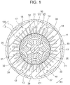
- FIG. 1 is a sectional view illustrating a motor 100 of the first embodiment.
- the motor 100 is a brushless DC motor and is used in a compressor 500 ( FIG. 20 ) described later.
- the motor 100 is a reluctance motor (more specifically, a synchronous reluctance motor) that generates a driving force by reluctance torque without using a permanent magnet.
- the motor 100 includes a stator 1 and a rotor 3 rotatably provided on an inner side of the stator 1. An air gap is formed between the stator 1 and the rotor 3.
- the stator 1 is incorporated on an inner circumferential surface 41 side of a cylindrical shell 4 of the compressor 500.
- the rotor 3 includes a cylindrical rotor core 30.
- the rotor core 30 includes stacking steel sheets (electromagnetic steel sheets) each having a thickness of 0.25 to 0.5 mm, for example, which are stacked in a direction of a rotation axis and are fixed by crimping or the like.
- a circular shaft hole 37 is formed at a center of the rotor core 30 in a radial direction.
- a shaft 38 that is a rotation shaft is fixed to the shaft hole 37 by press fitting.
- An axis C1 that is a center axis of the shaft 38 defines the rotation axis of the rotor 3.
- a direction of the axis C1 of the shaft 38 is referred to as an "axial direction”.
- a direction of a circumference about the axis C1 (indicated by an arrow R1 in FIG. 1 and the like) is referred to as a “circumferential direction”.
- a direction of a radius about the axis C1 is referred to as a "radial direction”.
- FIG. 2 is a sectional view illustrating the rotor 3.
- the rotor 3 has an annular outer circumferential surface 30a (an outer circumference) extending in the circumferential direction, and has six magnetic poles in the circumferential direction.
- the pole number P of the rotor 3 is six.
- the six magnetic poles are indicated by marks P1, P2, P3, P4, P5, and P6.
- the pole number P is not limited to six, and it is sufficient that the pole number P is two or more.
- a center position of each magnetic pole in the circumferential direction is a pole center.
- a part between magnetic poles adjacent to each other in the circumferential direction is an inter-pole part (indicated by mark M in FIG. 2 ).
- First slits 31 are formed along the outer circumference of the rotor core 30.
- Second slits 32 are formed on inner sides of the respective first slits 31 in the radial direction.
- the first slit 31 and the second slit 32 correspond to one magnetic pole. In other words, each of the six magnetic poles has the first slit 31 and the second slit 32.
- the first slit 31 and the second slit 32 are also referred to as a flux barrier.
- Each first slit 31 has an arc shape such that a center part 31a in the circumferential direction protrudes inward in the radial direction with respect to both end parts 32b in the circumferential direction.
- each second slit 32 has an arc shape such that a center part 32a in the circumferential direction protrudes inward in the radial direction with respect to both ends 32b in the circumferential direction.
- the center part 31a of the first slit 31 and the center part 32a of the second slit 32 are located on the same axis (an axis in the radial direction) passing through the axis C1.
- This axis corresponds to a q-axis (that is, a center line of a magnetic pole).
- an axis in the radial direction passing through between the magnetic poles adjacent to each other in the circumferential direction corresponds to a d-axis (that is, a center line of the inter-pole part).
- FIG. 3 is an enlarged diagram illustrating a part of the rotor core 30 including one magnetic pole.
- Each of the first slits 31 has an outer circumferential end side 311 having an arc shape and an inner circumferential end side 312 having an arc shape.
- a region B1 in which magnetic flux from the stator 1 flows is formed between the first slit 31 and the outer circumferential surface 30a of the rotor core 30 (more specifically, between the outer circumferential end side 311 of the first slit 31 and the outer circumferential surface 30a of the rotor core 30).
- Each of the second slits 32 has an outer circumferential end side 321 having an arc shape and an inner circumferential end side 322 having an arc shape.
- a region B2 in which magnetic flux from the stator 1 flows is formed between the first slit 31 and the second slit 32 (more specifically, between the inner circumferential end side 312 of the first slit 31 and the outer circumferential end side 321 of the second slit 32).
- an inner circumferential side region B3 in which less magnetic flux from the stator 1 flows is formed in a region surrounded by the second slits 32 of the six magnetic poles (more specifically, a region surrounded by the inner circumferential end sides 312 of the second slits 32).
- the first slit 31 and the second slit 32 of the rotor core 30 generate a difference between d-axis inductance Ld and q-axis inductance Lq, so that reluctance torque is generated.
- an outer circumferential bridge that is a thin wall part is formed between the end part 31b of the first slit 31 and the outer circumferential surface 30a of the rotor core 30.
- an outer circumferential bridge that is a thin wall part is formed between the end part 32b of the second slit 32 and the outer circumferential surface 30a of the rotor core 30.
- a thickness of each outer circumferential bridge is the same as a thickness of each stacking steel sheet, for example.
- the circular shaft hole 37 is formed at the center of the rotor core 30 in the radial direction, and the shaft 38 ( FIG. 2 ) is fitted to the shaft hole 37.
- Groove parts 35 are formed to extend outward in the radial direction from an outer circumferential surface of the shaft hole 37. Each groove part 35 passes through the rotor core 30 in the axial direction. An outer end part 35a of the groove part 35 in the radial direction is close to the center part 32a of the second slit 32. The shortest distance between the end part 35a of the groove part 35 and the second slit 32 is the same as the thickness of each stacking steel sheet, for example.
- each groove part 35 in the circumferential direction corresponds to each magnetic pole.
- a center line of each groove part 35 is aligned with the center line of the magnetic pole.
- the groove parts 35 are not closed. Therefore, refrigerant flows in the axial direction through the inside of the groove parts 35.
- the groove parts 35 constitute refrigerant passages through which refrigerant passes.
- the groove parts 35 are formed continuously with the shaft hole 37, the groove parts 35 may be apart from the shaft hole 37 outward in the radial direction.
- the number of the groove parts 35 is not limited to the same number as the pole number P, and it is sufficient that the number of the groove parts 35 is one or more.
- the stator 1 includes a stator core 10 and a winding 2 ( FIG. 5 ) wound around the stator core 10 in wave winding.
- the stator core 10 is obtained by stacking a plurality of stacking steel sheets (electromagnetic steel sheets) each having a thickness of 0.25 to 0.5 mm, for example, in the axial direction and fixing the sheets by crimping parts 17.
- the stator core 10 includes an annular yoke part 11 that extends in the circumferential direction and a plurality of teeth 12 extending inward in the radial direction from the yoke part 11.
- a slot 13 is formed between each two teeth 12 adjacent to each other in the circumferential direction.
- the slots 13 are parts for accommodating the winding 2 wound around the teeth 12, and extend in the radial direction.
- the number of the teeth 12 and the number of the slots 13 are the same as each other, and are thirty-six in the example illustrated in FIG. 1 . That is, six slots 13 correspond to each magnetic pole of the rotor 3.
- the slot number S is 3n (n is a natural number) times the pole number P. Therefore, a ratio S/P of the slot number S to the pole number P is 3, 6, 9, 12, and 15, for example.
- Cutout parts 16 are formed on an outer circumferential surface 18 of the stator core 10. Each cutout part 16 is formed by cutting the cylindrical outer circumferential surface 18 by a plane parallel to the axis C1, and extends over the entire region of the stator core 10 in the axial direction. The cutout parts 16 are formed at a plurality of positions in the circumferential direction in the yoke part 11. In this example, six cutout parts 16, the number of which is the same as the pole number P, are arranged at equal intervals in the circumferential direction. A refrigerant passage through which refrigerant passes in the axial direction is formed between the cutout part 16 and the inner circumferential surface 41 of the shell 4.
- the crimping parts 17 for fixing the stacking steel sheets of the stator core 10 to each other are formed in the yoke part 11.
- a reason why the crimping parts 17 are not formed in the teeth 12 but formed in the yoke part 11 is to prevent the crimping parts 17 from obstructing a flow of magnetic flux.
- six crimping parts 17, the number of which is the same as the pole number P, are arranged at equal intervals in the circumferential direction.
- the crimping parts 17 are formed at positions corresponding to center parts of the cutout parts 16 in the circumferential direction.
- FIG. 4 is an enlarged schematic diagram illustrating a part of the stator 1.
- a width (a length in the circumferential direction) of each tooth 12 decreases toward the tip 12a of the tooth 12. That is, a width W1 of the tooth 12 at the tip 12a (an inner end in the radial direction) is narrower than a width W2 of the tooth 12 at its base 12b (an outer end in the radial direction) .
- a length of the tooth 12 in the radial direction (that is, a distance from the base 12b to the tip 12a) is represented by H1.
- H1 is also a length of each slot 13.
- a distance from the base 12b of the tooth 12 to the outer circumferential surface 18 of the yoke part 11 (a yoke width) is represented by H2.
- the yoke width H2 is a width of a magnetic path that flows in the yoke part 11 in the circumferential direction.
- the winding 2 is arranged in a row in each slot 13.
- a width Ws of the slot 13 in the circumferential direction is set to such a width that the winding 2 is arranged in a row. That is, the slot 13 has a rectangular shape having the width Ws in the circumferential direction and the length H1 in the radial direction.
- An inner end of the slot 13 in the radial direction is an opening 13a through which the winding 2 is inserted, and an outer end of the slot 13 in the radial direction is a closed end 13b.
- FIG. 5 is a perspective view illustrating the motor 100 in which the winding 2 is wound around the stator core 10.
- the winding 2 is wound around thirty-six teeth 12 ( FIG. 1 ) of the stator core 10 in wave winding. Since the winding 2 is wound in wave winding, an outward protruding amount of the winding 2 in the radial direction from the teeth 12 is small. Therefore, the winding 2 does not obstruct a flow of refrigerant passing through the cutout parts 16.
- a protruding amount of the winding 2 in the axial direction from the stator core 10 is also small, as compared with a case where the winding 2 is wound in concentric winding.
- the protruding amount of the winding 2 in the axial direction is small, the lengths of the stator core 10 and the rotor core 30 in the axial direction can be increased.
- lengths of parts (parts inserted into the slots 13) other than coil end parts can be increased, and thus higher torque can be obtained.
- the winding 2 is a conductor (for example, copper) on which a corrosion-resistant cover layer such as a cover layer of polyesterimide or polyamideimide is formed. This is because the winding 2 is in contact with refrigerant that circulates in the compressor 500 in which the motor 100 is provided.
- FIG. 6 is a schematic diagram illustrating the winding 2 wound in wave winding.
- the winding 2 has a straight part 22 inserted in the slots 13 ( FIG. 1 ), a coil end part 21 extending in the circumferential direction on one end surface of the rotor core 30 in the axial direction, and a coil end part 23 extending in the circumferential direction on the other end surface of the rotor core 30 in the axial direction.
- eight winding parts 20 of the winding 2 are inserted in each slot 13 ( FIG. 1 ).
- FIG. 7 is an enlarged diagram illustrating a part of the coil end part 21 of the winding 2.
- nine winding parts 20 are wound at the same winding position in the radial direction (for example, an innermost position) in such a manner that positions of the winding parts 20 in the circumferential direction are shifted from each other by one slot.
- Three of the nine winding parts 20 wound at the innermost position are referred to as winding parts 20a, 20b, and 20c.
- FIG. 8 is a schematic diagram illustrating one winding part 20a.
- the winding part 20a has two coil end parts 21a, four straight parts 22a, and two coil end parts 23a.
- the winding part 20a is wound so as to span nine teeth 12. That is, the straight parts 22a of the winding part 20a are inserted in every nine slots 13.
- the coil end part 21a extends to connect ends of the straight parts 22a in the axial direction (upper ends in FIG. 8 ) to each other, and the coil end part 23a extends to connect the other ends of the straight parts 22a in the axial direction (lower ends in FIG. 8 ) to each other.
- the coil end parts 21a and the coil end parts 23a are alternately arranged in the circumferential direction about the axis C1.
- a nose part 25a is provided at a center part of the coil end part 21a in the circumferential direction, and the coil end part 21a is displaced in the radial direction by a displacement amount E1 at the nose part 25a.
- the coil end part 21a extends clockwise in the circumferential direction about the axis C1 as indicated by an arrow A1 in FIG. 8 , is displaced inward in the radial direction by the displacement amount E1 at the nose part 25a, and extends again in the direction indicated by the arrow A1.
- a nose part 26a is provided at a center part of the coil end part 23a in the circumferential direction, and the coil end part 23a is displaced in the radial direction by the displacement amount E1 at the nose part 26a.
- the coil end part 23a extends clockwise in the circumferential direction about the axis C1 as indicated by an arrow A2 in FIG. 8 , is displaced outward in the radial direction by the displacement amount E1 at the nose part 26a, and extends again in the direction indicated by the arrow A2.
- FIG. 9 is a schematic diagram illustrating the two winding parts 20a and 20b.
- the winding part 20b has two coil end parts 21b, four straight parts 22b, and two coil end parts 23b, as is the case with the winding part 20a.
- the straight part 22b of the winding part 20b is shifted clockwise about the axis C1 with respect to the straight part 22a of the winding part 20a by one slot.
- a nose part 25b is provided at a center part of the coil end part 21b in the circumferential direction, as is the case with the nose part 25a of the coil end part 21a.
- a nose part 26b is provided at a center part of the coil end part 23b in the circumferential direction, as is the case with the nose part 26a of the coil end part 23a.
- the coil end parts 21a and 21b of the winding parts 20a and 20b extend in the circumferential direction while overlapping each other in the axial direction, and their vertical positions (positions in the axial direction) are inverted to each other through the nose parts 25a and 25b.
- the coil end parts 23a and 23b of the winding parts 20a and 20b extend in the circumferential direction while overlapping each other in the axial direction, and their vertical positions (positions in the axial direction) are inverted to each other through the nose parts 26a and 26b. Therefore, the straight parts 22a and 22b of the winding parts 20a and 20b can be inserted in the slots 13 adjacent to each other ( FIG. 1 ) without interfering with each other.
- FIG. 9 illustrates the two winding parts 20a and 20b only, nine winding parts 20 in total including these winding parts 20a and 20b are wound at the same winding position (for example, at the innermost position) in the radial direction as the winding parts 20a and 20b. That is, the straight part 22 of the winding 20 is inserted in each of the thirty-six slots 13 of the stator core 10.
- FIG. 10 is a schematic diagram illustrating eight winding parts 20 in total inserted in the same slots 13 in which the winding part 20a illustrated in FIG. 8 is inserted.
- the eight winding parts 20 are wound at equal intervals in the radial direction.
- the winding 2 in wave winding illustrated in FIG. 6 is formed.
- the number of the winding parts 20 inserted in each slot 13 and the number of the teeth 12 spanned by each winding part 20 are not limited to those in the example illustrated in FIGS. 6 to 10 , and can be set to any numbers in accordance with the pole number P and the slot number S.
- FIG. 11 is a diagram illustrating an analysis result of a magnetic flux distribution in the motor 100 in the case where the groove part 35 is not provided in the rotor core 30.
- a current is made to flow in the winding 2 (omitted in FIG. 11 ) in the slot 13 of the stator 1
- magnetic flux generated by the winding current is distributed as illustrated in FIG. 11 .
- magnetic flux flows in the regions B1 on the outer circumferential side of the first slits 31 and the band-shaped regions B2 between the first slits 31 and the second slits 32. Meanwhile, magnetic flux flowing in the inner circumferential side region B3 surrounded by the second slits 32 of the six magnetic poles is little.
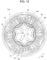
- FIG. 12 is a diagram illustrating an analysis result of a magnetic flux distribution in the motor 100 in the case where the groove part 35 is provided in the rotor core 30.
- the groove parts 35 are formed in the inner circumferential side region B3 of the rotor core 30, and little magnetic flux flows in the inner circumferential side region B3. Therefore, the groove parts 35 do not obstruct a flow of magnetic flux in the rotor core 30 and therefore do not affect magnetic characteristics of the motor 100.
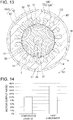
- FIG. 13 is a sectional view illustrating a motor 100D of a comparative example in a cross-section perpendicular to the axis C1.
- the motor 100D of the comparative example includes a stator 1D and a rotor 3D.
- the stator 1D includes a stator core 10D and a winding 2D wound around the stator core 10D.
- the stator core 10D includes an annular yoke part 11D and eighteen teeth 12D protruding inward in the radial direction from the yoke part 11D.
- a slot 13D is formed between each two teeth 12D adjacent to each other in the circumferential direction.
- the winding 2D is wound around the teeth 12D in concentric winding.
- the rotor 3D has the same configuration as the rotor 3 of the first embodiment except that the rotor 3D is not provided with the groove part 35.
- the winding 2D is wound in concentric winding, and thus coil end parts are large. Therefore, in order to accommodate the motor 100D in a limited space within a compressor, it is necessary to shorten lengths of the stator core 10D and the rotor core 30D in the axial direction.
- FIG. 14 is a graph illustrating in comparison an output of the motor 100 of the first embodiment ( FIG. 1 ) and an output of the motor 100D of comparative example ( FIG. 13 ).
- the motor output of the motor 100 of the first embodiment and that of the motor 100D of the comparative example are compared assuming that the motors have the same entire sizes (dimensions in the axial and radial directions).
- the winding 2 wound in wave winding has smaller coil end parts than the winding 2 wound in concentric winding. Therefore, in the motor 100 of the first embodiment, it is possible to increase the lengths of the stator core 10 and the rotor core 30 in the axial direction, and to increase the length of the winding 2 inserted in the slots 13 (a length that contributes to generation of a driving force), in comparison with the motor 100D of the comparative example having the same size.
- the motor 100 of the first embodiment can generate a higher output than the motor 100D of the comparative example.
- the analysis result in FIG. 14 shows that the motor 100 of the first embodiment generates an output higher than the motor 100D of the comparative example by 60%.
- the motor 100 of the first embodiment can generate a high output although the motor 100 is a reluctance motor having no permanent magnet.
- each magnetic pole Although two slits (the first slit 31 and the second slit 32) are formed in each magnetic pole in this example, three or more slits may be formed in each magnetic pole. In such a case, an outermost slit in each magnetic pole is referred to as the first slit, and an innermost slit is referred to as the second slit.
- the motor 100 of the first embodiment of the present invention is a reluctance motor having the first slit 31 and the second slit 32 in each magnetic pole of the rotor 3, the winding 2 is wound around the stator core 10 in wave winding, and the cutout parts 16 (refrigerant passages) through which refrigerant flows in the axial direction are formed in the stator core 10.
- the winding 2 Since the winding 2 is wound in wave winding, the coil end parts are small. Therefore, it is possible to increase the lengths of the stator core 10 and the rotor core 30 in the axial direction and the length of the winding 2 that contributes to generation of a driving force, without increasing the entire size of the motor 100. As a result, a high output can be obtained even by a reluctance motor having no permanent magnet.
- the winding 2 is wound in wave winding and the outward protruding amount of the winding in the radial direction is small. Therefore, a flow of refrigerant passing through the cutout parts 16 is not obstructed by the winding 2, and thus a sufficient flow rate of refrigerant can be obtained. That is, it is possible to flow a sufficient amount of refrigerant in accordance with enhancement in output of the motor 100.
- groove parts 35 that pass through the rotor core 30 in the radial direction are formed on the outer side in the radial direction of the shaft hole 37 of the rotor core 30, it is possible to increase a flow rate of refrigerant without obstructing a flow of magnetic flux in the rotor core 30.
- the groove parts 35 are formed continuously with the shaft hole 37, it is easy to process the stacking steel sheets and it is possible to increase an area of the groove parts 35 (that is, an area of flow passages).
- the slit 31 has an arc shape such that the center part 31a in the circumferential direction protrudes inward in the radial direction with respect to both end parts 31b
- the slit 32 has an arc shape such that the center part 32a in the circumferential direction protrudes inward in the radial direction with respect to both end parts 32b. Therefore, it is possible to make a difference between d-axis inductance Ld and q-axis inductance Lq and to thereby generate reluctance torque.
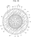
- FIG. 15 is a sectional view illustrating a configuration of a motor 100A of the second embodiment in a plane perpendicular to the axis C1.
- the motor 100A includes the stator 1 and a rotor 3A.
- the stator 1 of the motor 100A has the same configuration as the stator 1 of the motor 100 of the first embodiment. That is, the stator core 10 of the stator 1 includes the yoke part 11 and the teeth 12, the winding 2 is wound around the teeth 12 in wave winding, and the cutout parts 16 (refrigerant passages) through which refrigerant flows in the axial direction are formed in the yoke part 11.
- the rotor 3A of the motor 100A is obtained by providing crimping parts 33 and rivet holes (through holes) 34 in the rotor 3 of the motor 100 of the first embodiment. Both of the number of the crimping parts 33 and the number of the rivet holes 34 are the same as the pole number P. Since the pole number P is six in this example, both of the number of the crimping parts 33 and the number of the rivet holes 34 are six.
- FIG. 16 is an enlarged view illustrating a part of the rotor 3A.
- the crimping parts 33 of the rotor 3 are provided for fixing stacking steel sheets of the rotor core 30 to each other.
- the crimping parts 33 are formed in the inner circumferential side region B3 surrounded by the second slits 32 of the magnetic poles in the rotor core 30.
- the crimping parts 33 are formed in the inter-pole parts. More specifically, each crimping part 33 is formed at a position between two second slits 32 adjacent to each other in the circumferential direction.
- the rivet holes 34 of the rotor 3 are formed in the inner circumferential side region B3 surrounded by the second slits 32 of the magnetic poles in the rotor core 30, as is the case with the crimping parts 33. Moreover, the rivet holes 34 are formed in the inter-pole parts and are located on the inner sides of the crimping parts 33 in the radial direction.
- a flow of magnetic flux is little in the inner circumferential side region B3 surrounded by the second slits 32 of the magnetic poles in the rotor core 30. Therefore, the crimping parts 33 and the rivet holes 34 do not obstruct a flow of magnetic flux in the rotor core 30.
- an area occupied by opening parts (the slits 31 and 32) in the rotor core 30 of the reluctance motor is larger, and thus a region where the crimping parts 33 can be formed is smaller.
- the rivet holes 34 in which the rivets are inserted occupy a wider area than the crimping parts 17. Therefore, in the second embodiment, the rivet holes 34 are formed on the inner sides of the crimping parts 33 in the radial direction.
- the crimping parts 33 and the rivet holes 34 are formed in all of the six inter-pole parts. Thus, a weight balance of the rotor core 30 in the circumferential direction is enhanced. Although the six crimping parts 33 and the six rivet holes 34 are formed in this example, it is sufficient that at least one crimping part 33 and at least one rivet hole 34 are formed.
- both of the crimping part 33 and the rivet hole 34 are formed in the rotor core 30 in this example, it is possible that only the crimping part 33 is formed in the rotor core 30 or only the rivet holes 34 is formed in the rotor core 30.
- the rivet holes 34 may be used as through holes through which refrigerant passes in the axial direction.
- the crimping parts 33 and the rivet holes 34 are formed in a region surrounded by innermost slits (referred to as the second slits) of the magnetic poles.
- the crimping parts 33 are formed in the inner circumferential side region B3 surrounded by the second slits 32 of the magnetic poles in the rotor core 30. Therefore, it is possible to form the crimping parts 33 so as not to obstruct a flow of magnetic flux in the rotor core 30, and thus the stacking elements of the rotor core 30 can be fixed strongly.
- the rivet holes (the through holes) 34 are formed on the inner sides of the crimping parts 33 in the radial direction. Therefore, it is possible to form the rivet holes 34 so as not to obstruct a flow of magnetic flux in the rotor core 30, and thus the stacking elements of the rotor core 30 can be fixed further strongly.
- the crimping parts 33 and the rivet holes 34 are formed in the inter-pole parts, it is possible to effectively use a limited space of the inner circumferential side region B3 of the rotor core 30. Since the crimping parts 33 and the rivet holes 34 are formed in all of the inter-pole parts, a weight balance of the rotor core 30 in the circumferential direction is enhanced.
- FIG. 17 is a sectional view illustrating a configuration a motor 100B of the third embodiment in a plane perpendicular to the axis C1.
- the motor 100B includes the stator 1 and a rotor 3B.
- the stator 1 of the motor 100B has the same configuration as the stator 1 of the motor 100 of the first embodiment. That is, the stator core 10 of the stator 1 includes the yoke part 11 and the teeth 12, the winding 2 is wound around the teeth 12 in wave winding, and the cutout parts 16 (refrigerant passages) through which refrigerant flows in the axial direction are formed in the yoke part 11.
- the rotor 3B of the motor 100B is different from the rotor 3 of the motor 100 of the first embodiment in the shape of slits.
- the rotor 3B of the second embodiment has first slits 51 formed along the outer circumferential surface 30a of the rotor core 30 and second slits 52 formed on inner sides of the respective first slits 51 in the radial direction.
- the first slit 51 and the second slit 52 correspond to one magnetic pole. In other words, each of the six magnetic poles has the first slit 51 and the second slit 52.
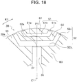
- FIG. 18 is an enlarged view illustrating a part of the rotor 3B.
- Each first slit 51 has a first part 51b that includes a center part 51a in the circumferential direction and linearly extends, and a pair of second parts 51c that linearly extend from both ends of the first part 51b in the circumferential direction toward the outer circumference of the rotor core 30.
- the first part 51b extends in a direction perpendicular to a line (a magnetic-pole center line) in the radial direction which passes through the center part 51a.
- the pair of second parts 51c extend symmetrically with respect to the line in the radial direction which passes through the center part 51a in such a manner that a distance between the second parts 51c increases outward in the radial direction.
- Each second slit 52 has a first part 52b that includes a center part 52a in the circumferential direction and linearly extends, and a pair of second parts 52c that linearly extend from both ends of the first part 52b in the circumferential direction toward the outer circumference of the rotor core 30.
- the first part 52b extends in a direction perpendicular to a line (a magnetic-pole center line) in the radial direction which passes through the center part 52a.
- the pair of second parts 52c extend symmetrically with respect to the line in the radial direction which passes through the center part 52a in such a manner that a distance between the second parts 52c increases outward in the radial direction.
- the region B1 in which magnetic flux from the stator 1 flows is formed on the outer circumferential side of the first slit 51.
- the band-shaped region B2 in which magnetic flux from the stator 1 flows is formed between the first slit 51 and the second slit 52.
- the inner circumferential side region B3 where less magnetic flux flows is formed.
- the configurations of the shaft hole 37 and the groove parts 35 of the rotor core 30 are the same as those in the first embodiment. Moreover, the crimping parts 33 and the rivet holes 34 described in the second embodiment may be formed in the inner circumferential side region B3 of the rotor core 30.
- the reluctance motor includes the first slit 51 and the second slit 52 in each magnetic pole of the rotor 3B, the winding 2 is wound around the stator core 10 in wave winding, and the cutout parts 16 (refrigerant passages) through which refrigerant flows in the axial direction are formed in the stator core 10. Therefore, it is possible to obtain a high output without increasing the entire size of the motor 100B, as in the first embodiment. Moreover, the winding 2 is wound in wave winding and the outward protruding amount of the winding 2 in the radial direction is small. Therefore, a sufficient flow rate of refrigerant passing through the cutout parts 16 can be obtained.
- groove parts 35 that pass through the rotor core 30 in the radial direction are formed on the outer side in the radial direction of the shaft hole 37 of the rotor core 30, it is possible to increase a flow rate of refrigerant without obstructing a flow of magnetic flux in the rotor core 30.
- FIG. 19 is a sectional view illustrating a configuration of a motor 100C of the third embodiment in a plane perpendicular to the axis C1.
- the motor 100C includes a stator 1C and the rotor 3.
- the stator 1C of the motor 100C includes the stator core 10 and the winding 2.
- the stator core 10 includes the yoke part 11 and the teeth 12, and the winding 2 is wound around the teeth 12 in wave winding, as in the first embodiment.
- through holes 15 through which refrigerant flows in the axial direction are formed in the yoke part 11, in place of the cutout parts 16.
- Each through hole 15 is located, for example, on an axis in the radial direction which passes through the center position of the tooth 12 in the circumferential direction. Moreover, it is desirable that the through holes 15 and the crimping parts 17 of the stator core 10 are formed alternately in the circumferential direction.
- the cutout parts 16 ( FIG. 1 ) described in the first embodiment may be formed in the yoke part 11 in addition to the through holes 15.
- the number of the through holes 15 is not limited to the same number as the pole number P, and it is sufficient that the number of the through holes 15 is one or more.
- the rotor 3 of the motor 100C has the same configuration as the rotor 3 of the first embodiment.
- the crimping parts 33 and the rivet holes 34 may be formed in the rotor 3 as described in the second embodiment, or the shapes of the slits 51 and 52 described in the third embodiment may be employed.
- the through holes 15 through which refrigerant passes are formed in the yoke part 11 of the stator 1C, and the winding 2 is wound around the teeth 12 in wave winding. Therefore, a flow of refrigerant passing through the through holes 15 is not obstructed by the winding 2, so that a sufficient flow rate of refrigerant can be obtained. Moreover, by providing both of the through holes 15 and the cutout parts 16 in the yoke part 11 of the stator 1C, the flow rate of refrigerant can be further increased.
- FIG. 20 is a sectional view illustrating a configuration of the compressor (scroll compressor) 500 in which the motor 100 of the above described first embodiment is used.
- the compressor 500 is a scroll compressor and includes, in a closed container 502, a compression mechanism 510, the motor 100 that drives the compression mechanism 510, a main shaft 501 that connects the compression mechanism 510 and the motor 100 to each other, a sub-frame 503 that supports an end (a sub-shaft part) of the main shaft 501 opposite to the compression mechanism 510, and a lubricant 504 stored in an oil reservoir 505 at a bottom of the closed container 502.
- the compression mechanism 510 has a fixed scroll 511 and an orbiting scroll 512 attached to the main shaft 501. Each of the fixed scroll 511 and the orbiting scroll 512 has a spiral part, and a spiral compression chamber 516 is formed between the fixed scroll 511 and the orbiting scroll 512.
- the compression mechanism 510 further includes an Oldham ring 513 that regulates rotation of the orbiting scroll 512 to make the orbiting scroll 512 swing, a compliant frame 514 to which the orbiting scroll 512 is attached, and a guide frame 515 that supports these components.
- a suction pipe 506 passing through the closed container 502 is press-fitted to the fixed scroll 511. Moreover, a discharge pipe 507 is provided so as to pass through the closed container 502. The discharge pipe 507 allows high-pressure refrigerant gas discharged from a discharge port 511a of the fixed scroll 511 to be discharged to the outside.
- the closed container 502 includes the cylindrical shell 4 ( FIG. 1 ).
- the motor 100 of the first embodiment is attached to the inner circumferential side of the shell 4.
- a glass terminal 508 for electrically connecting the stator 1 of the motor 100 and a driving circuit to each other is fixed to the closed container 502 by welding.
- the main shaft 501 is the shaft 38 of the motor 100 ( FIG. 1 ).
- An operation of the compressor 500 is as follows.
- the main shaft 501 (the shaft 38) rotates together with the rotor 3.
- the orbiting scroll 512 swings to change a volume of the compression chamber 516 between the fixed scroll 511 and the orbiting scroll 512.
- refrigerant gas is sucked through the suction pipe 506 into the compression chamber 516 and is compressed.
- the high-pressure refrigerant gas compressed in the compression chamber 516 is discharged into the closed container 502 through the discharge port 511a of the fixed scroll 511, and is discharged to the outside through the discharge pipe 507. Moreover, part of the refrigerant gas discharged into the closed container 502 from the compression chamber 516 passes through the cutout parts 16 of the stator 1 ( FIG. 1 ) and cools the motor 100 and the lubricant 504.
- the motor 100 of the first embodiment generates high torque and manufacturing cost of the motor 100 is low. Therefore, an output of the compressor 500 can be increased and manufacturing cost of the compressor 500 can be reduced.
- any of the motors 100A to 100C described in the second to fourth embodiments may be used in the compressor 500.
- a scroll compressor has been described here as an example of a compressor, the motors 100 to 100C of the first to fourth embodiments may be applied to a compressor other than a scroll compressor.
- FIG. 21 is a diagram illustrating a configuration of an air conditioner 400.
- the air conditioner 400 illustrated in FIG. 21 includes a compressor 401, a condenser 402, a restrictor (a decompressor) 403, and an evaporator 404.
- the compressor 401, the condenser 402, the restrictor 403, and the evaporator 404 are connected by a refrigerant pipe 407 to constitute a refrigerating cycle. That is, refrigerant circulates through the compressor 401, the condenser 402, the restrictor 403, and the evaporator 404 in this order.
- the compressor 401, the condenser 402, and the restrictor 403 are provided in an outdoor unit 410.
- the compressor 401 is constituted by the compressor 500 illustrated in FIG. 20 .
- An outdoor fan 405 for supplying outdoor air to the condenser 402 is provided in the outdoor unit 410.
- the evaporator 404 is provided in an indoor unit 420.
- An indoor fan 406 for supplying indoor air to the evaporator 404 is provided in the indoor unit 420.
- An operation of the air conditioner 400 is as follows.
- the compressor 401 compresses sucked refrigerant and sends out the compressed refrigerant.
- the condenser 402 exchanges heat between the refrigerant flowing from the compressor 401 and the outdoor air, condenses and liquefies the refrigerant, and sends out the liquefied refrigerant to the refrigerant pipe 407.
- the outdoor fan 405 supplies the outdoor air to the condenser 402.
- the restrictor 403 changes its opening degree to thereby adjust a pressure or the like of the refrigerant flowing through the refrigerant pipe 407.
- the evaporator 404 exchanges heat between the refrigerant brought into a low pressure state by the restrictor 403 and the indoor air, causes the refrigerant to take heat from the air and evaporate (vaporize), and sends out the refrigerant to the refrigerant pipe 407.
- the indoor fan 406 supplies the indoor air to the evaporator 404.
- cool wind deprived of heat by the evaporator 404 is supplied into a room.
- any of the motors 100 to 100C described in the first to fourth embodiments is applicable to the compressor 401 (the compressor 500 in FIG. 20 ), air conditioning performance of the air conditioner 400 can be increased and manufacturing cost of the air conditioner 400 can be reduced.
- the compressor 500 to which any of the motors 100 to 100C of the first to fourth embodiments is applied is not limited to use in the air conditioner 400 illustrated in FIG. 21 .
- the compressor 500 may be used in another type of air conditioner.
- stator core 11 yoke part; 12 tooth; 12a tip; 12b base; 13 slot; 15 through hole: 16 cutout part; 17 crimping part; 18 outer circumferential surface; 20, 20a, 20b, 20c winding part; 30 rotor core; 31 first slit; 31a center part; 31b end part; 32 second slit; 32a center part; 32b end part; 33 crimping part; 34 rivet hole; 35 groove part; 37 shaft hole; 38 shaft; 51 first slit; 51a center part; 51b first part; 51c second part; 52 second slit; 52a center part; 52b first part; 52c second part; 100, 100A, 100B, 100C motor; 400 air conditioner; 401 outdoor unit; 402 indoor unit; 403 refrigerant pipe; 405 fan; 406 blade; 500 compressor (scroll compressor);
Landscapes
- Engineering & Computer Science (AREA)
- Power Engineering (AREA)
- Physics & Mathematics (AREA)
- Mechanical Engineering (AREA)
- Thermal Sciences (AREA)
- General Engineering & Computer Science (AREA)
- Iron Core Of Rotating Electric Machines (AREA)
- Motor Or Generator Cooling System (AREA)
- Synchronous Machinery (AREA)
- Applications Or Details Of Rotary Compressors (AREA)
Abstract
Description
- The present invention relates to a reluctance motor, and a compressor and an air conditioner in each of which the reluctance motor is used.
- A reluctance motor (more specifically, a synchronous reluctance motor) has been conventionally developed in order to reduce power consumption and reduce manufacturing cost. The reluctance motor does not include a permanent magnet, but includes a slit formed in a magnetic pole of a rotor, so that a driving force is obtained by means of reluctance torque.
- For example,
Patent References -
Patent Reference 3 discloses a technique in which a rotor of a reluctance motor is divided into a permanent magnet rotor part and a reluctance rotor part to thereby suppress reduction in reluctance torque due to magnetic saturation. -
- Patent Reference 1: Japanese Patent Application Publication No.
2013-192359 FIG. 2 ) - Patent Reference 2: Japanese Patent Application Publication No.
2011-83066 FIG. 1 ) - Patent Reference 3: Japanese Patent Application Publication No.
2004-88852 FIG. 2 ) - In order to reduce manufacturing cost of a reluctance motor, it is desirable not to use a permanent magnet. However, in order to obtain high torque only by reluctance torque, it is necessary to increase a size of a reluctance motor. It is difficult to accommodate such a reluctance motor in a limited space inside a compressor.
- Moreover, in a compressor in which refrigerant flows in an axial direction through a through hole (a wind hole) or the like formed in a rotor, it is necessary to increase a flow rate of the refrigerant with an increase in torque.
- The present invention is made to solve the above problems, and an object of the present invention is to provide a reluctance motor that can be accommodated in a limited space in a compressor, can generate high torque, and can provide a sufficient flow rate of refrigerant.
- A reluctance motor of the present invention is used in a compressor. The reluctance motor includes a rotor having a rotor core that has an annular outer circumference about an axis, having a plurality of magnetic poles along the outer circumference, and having no permanent magnet, and a stator having a stator core surrounding the rotor from an outer side in a radial direction about the axis and a winding wound around the stator core in wave winding. Each of the plurality of magnetic poles has a first slit formed in the rotor core and a second slit formed on an inner side of the first slit in the radial direction. The stator core has a refrigerant passage through which refrigerant passes in a direction of the axis.
- In the present invention, since the winding is wound in wave winding, coil end parts can be made small. Therefore, the rotor core and the stator core can be made large in the direction of the axis without making the reluctance motor entirely large, and thus high torque can be obtained. Moreover, since the refrigerant passage is provided in the stator core, a flow rate of the refrigerant in the compressor can be increased.
-
-
FIG. 1 is a sectional view illustrating a motor (a reluctance motor) of a first embodiment. -
FIG. 2 is a sectional view illustrating a rotor of the motor of the first embodiment. -
FIG. 3 is an enlarged diagram illustrating a part of the rotor of the motor of the first embodiment. -
FIG. 4 is an enlarged schematic diagram illustrating a tooth and its surrounding part of the motor of the first embodiment. -
FIG. 5 is a perspective view illustrating the motor of the first embodiment. -
FIG. 6 is a perspective view illustrating a winding of the first embodiment. -
FIG. 7 is an enlarged schematic diagram illustrating a part of the winding of the first embodiment. -
FIG. 8 is a perspective view illustrating one winding part of the winding of the first embodiment. -
FIG. 9 is a perspective view illustrating two winding parts of the winding of the first embodiment. -
FIG. 10 is a perspective view illustrating winding parts inserted into the same slot of a stator of the first embodiment. -
FIG. 11 is a diagram illustrating an analysis result of a magnetic flux distribution in the motor of the first embodiment in a case where no groove part is provided in the rotor. -
FIG. 12 is a diagram illustrating an analysis result of a magnetic flux distribution in the motor of the first embodiment in a case where a groove part is provided in the rotor. -
FIG. 13 is a sectional view illustrating a motor of a comparative example. -
FIG. 14 is a graph illustrating in comparison a motor output in the first embodiment and a motor output in the comparative example. -
FIG. 15 is a sectional view illustrating a motor of a second embodiment. -
FIG. 16 is an enlarged view illustrating a part of a rotor of the motor of the second embodiment. -
FIG. 17 is a sectional view illustrating a motor of a third embodiment. -
FIG. 18 is an enlarged view illustrating a part of a rotor of the motor of the third embodiment. -
FIG. 19 is a sectional view illustrating a motor of a fourth embodiment. -
FIG. 20 is a vertical sectional view illustrating a compressor to which the motor of each of the embodiments is applicable. -
FIG. 21 is a diagram illustrating an air conditioner including the compressor ofFIG. 20 . - A first embodiment of the present invention will be described.
FIG. 1 is a sectional view illustrating amotor 100 of the first embodiment. Themotor 100 is a brushless DC motor and is used in a compressor 500 (FIG. 20 ) described later. Moreover, themotor 100 is a reluctance motor (more specifically, a synchronous reluctance motor) that generates a driving force by reluctance torque without using a permanent magnet. - The
motor 100 includes astator 1 and arotor 3 rotatably provided on an inner side of thestator 1. An air gap is formed between thestator 1 and therotor 3. Thestator 1 is incorporated on an innercircumferential surface 41 side of acylindrical shell 4 of thecompressor 500. - The
rotor 3 includes acylindrical rotor core 30. Therotor core 30 includes stacking steel sheets (electromagnetic steel sheets) each having a thickness of 0.25 to 0.5 mm, for example, which are stacked in a direction of a rotation axis and are fixed by crimping or the like. Acircular shaft hole 37 is formed at a center of therotor core 30 in a radial direction. Ashaft 38 that is a rotation shaft is fixed to theshaft hole 37 by press fitting. An axis C1 that is a center axis of theshaft 38 defines the rotation axis of therotor 3. - Hereinafter, a direction of the axis C1 of the
shaft 38 is referred to as an "axial direction". A direction of a circumference about the axis C1 (indicated by an arrow R1 inFIG. 1 and the like) is referred to as a "circumferential direction". A direction of a radius about the axis C1 is referred to as a "radial direction". -
FIG. 2 is a sectional view illustrating therotor 3. Therotor 3 has an annular outercircumferential surface 30a (an outer circumference) extending in the circumferential direction, and has six magnetic poles in the circumferential direction. In other words, the pole number P of therotor 3 is six. InFIG. 2 , the six magnetic poles are indicated by marks P1, P2, P3, P4, P5, and P6. However, the pole number P is not limited to six, and it is sufficient that the pole number P is two or more. A center position of each magnetic pole in the circumferential direction is a pole center. A part between magnetic poles adjacent to each other in the circumferential direction is an inter-pole part (indicated by mark M inFIG. 2 ). - First slits 31 are formed along the outer circumference of the
rotor core 30.Second slits 32 are formed on inner sides of the respectivefirst slits 31 in the radial direction. Thefirst slit 31 and thesecond slit 32 correspond to one magnetic pole. In other words, each of the six magnetic poles has thefirst slit 31 and thesecond slit 32. Thefirst slit 31 and thesecond slit 32 are also referred to as a flux barrier. - Each first slit 31 has an arc shape such that a
center part 31a in the circumferential direction protrudes inward in the radial direction with respect to bothend parts 32b in the circumferential direction. Similarly, eachsecond slit 32 has an arc shape such that acenter part 32a in the circumferential direction protrudes inward in the radial direction with respect to both ends 32b in the circumferential direction. - In a cross-section perpendicular to the axis C1 illustrated in
FIG. 2 , thecenter part 31a of thefirst slit 31 and thecenter part 32a of thesecond slit 32 are located on the same axis (an axis in the radial direction) passing through the axis C1. This axis corresponds to a q-axis (that is, a center line of a magnetic pole). Meanwhile, an axis in the radial direction passing through between the magnetic poles adjacent to each other in the circumferential direction corresponds to a d-axis (that is, a center line of the inter-pole part). -
FIG. 3 is an enlarged diagram illustrating a part of therotor core 30 including one magnetic pole. Each of thefirst slits 31 has an outercircumferential end side 311 having an arc shape and an innercircumferential end side 312 having an arc shape. A region B1 in which magnetic flux from thestator 1 flows is formed between thefirst slit 31 and the outercircumferential surface 30a of the rotor core 30 (more specifically, between the outercircumferential end side 311 of thefirst slit 31 and the outercircumferential surface 30a of the rotor core 30). - Each of the second slits 32 has an outer
circumferential end side 321 having an arc shape and an innercircumferential end side 322 having an arc shape. A region B2 in which magnetic flux from thestator 1 flows is formed between thefirst slit 31 and the second slit 32 (more specifically, between the innercircumferential end side 312 of thefirst slit 31 and the outercircumferential end side 321 of the second slit 32). - Moreover, an inner circumferential side region B3 in which less magnetic flux from the
stator 1 flows is formed in a region surrounded by thesecond slits 32 of the six magnetic poles (more specifically, a region surrounded by the inner circumferential end sides 312 of the second slits 32). - The
first slit 31 and thesecond slit 32 of therotor core 30 generate a difference between d-axis inductance Ld and q-axis inductance Lq, so that reluctance torque is generated. - Moreover, an outer circumferential bridge that is a thin wall part is formed between the
end part 31b of thefirst slit 31 and the outercircumferential surface 30a of therotor core 30. Similarly, an outer circumferential bridge that is a thin wall part is formed between theend part 32b of thesecond slit 32 and the outercircumferential surface 30a of therotor core 30. A thickness of each outer circumferential bridge is the same as a thickness of each stacking steel sheet, for example. - The
circular shaft hole 37 is formed at the center of therotor core 30 in the radial direction, and the shaft 38 (FIG. 2 ) is fitted to theshaft hole 37.Groove parts 35 are formed to extend outward in the radial direction from an outer circumferential surface of theshaft hole 37. Eachgroove part 35 passes through therotor core 30 in the axial direction. Anouter end part 35a of thegroove part 35 in the radial direction is close to thecenter part 32a of thesecond slit 32. The shortest distance between theend part 35a of thegroove part 35 and thesecond slit 32 is the same as the thickness of each stacking steel sheet, for example. - With reference to
FIG. 2 again, thegroove parts 35 of the same number as the pole number P are formed in therotor core 30 in a radial pattern. Since the pole number P is six in this example, sixgroove parts 35 are formed. Moreover, a position of eachgroove part 35 in the circumferential direction corresponds to each magnetic pole. A center line of each groove part 35 (a line in the radial direction which defines a center of thegroove part 35 in the circumferential direction) is aligned with the center line of the magnetic pole. - Even in a state where the shaft 38 (
FIG. 1 ) is fitted into theshaft hole 37, thegroove parts 35 are not closed. Therefore, refrigerant flows in the axial direction through the inside of thegroove parts 35. Thegroove parts 35 constitute refrigerant passages through which refrigerant passes. Although thegroove parts 35 are formed continuously with theshaft hole 37, thegroove parts 35 may be apart from theshaft hole 37 outward in the radial direction. Moreover, the number of thegroove parts 35 is not limited to the same number as the pole number P, and it is sufficient that the number of thegroove parts 35 is one or more. - With reference to
FIG. 1 again, thestator 1 includes astator core 10 and a winding 2 (FIG. 5 ) wound around thestator core 10 in wave winding. Thestator core 10 is obtained by stacking a plurality of stacking steel sheets (electromagnetic steel sheets) each having a thickness of 0.25 to 0.5 mm, for example, in the axial direction and fixing the sheets by crimpingparts 17. - The
stator core 10 includes anannular yoke part 11 that extends in the circumferential direction and a plurality ofteeth 12 extending inward in the radial direction from theyoke part 11. Aslot 13 is formed between each twoteeth 12 adjacent to each other in the circumferential direction. Theslots 13 are parts for accommodating the winding 2 wound around theteeth 12, and extend in the radial direction. - The number of the
teeth 12 and the number of the slots 13 (referred to as the slot number S) are the same as each other, and are thirty-six in the example illustrated inFIG. 1 . That is, sixslots 13 correspond to each magnetic pole of therotor 3. In three-phase distributed winding, the slot number S is 3n (n is a natural number) times the pole number P. Therefore, a ratio S/P of the slot number S to the pole number P is 3, 6, 9, 12, and 15, for example. -
Cutout parts 16 are formed on an outercircumferential surface 18 of thestator core 10. Eachcutout part 16 is formed by cutting the cylindrical outercircumferential surface 18 by a plane parallel to the axis C1, and extends over the entire region of thestator core 10 in the axial direction. Thecutout parts 16 are formed at a plurality of positions in the circumferential direction in theyoke part 11. In this example, sixcutout parts 16, the number of which is the same as the pole number P, are arranged at equal intervals in the circumferential direction. A refrigerant passage through which refrigerant passes in the axial direction is formed between thecutout part 16 and the innercircumferential surface 41 of theshell 4. - Moreover, the crimping
parts 17 for fixing the stacking steel sheets of thestator core 10 to each other are formed in theyoke part 11. A reason why the crimpingparts 17 are not formed in theteeth 12 but formed in theyoke part 11 is to prevent the crimpingparts 17 from obstructing a flow of magnetic flux. In this example, six crimpingparts 17, the number of which is the same as the pole number P, are arranged at equal intervals in the circumferential direction. The crimpingparts 17 are formed at positions corresponding to center parts of thecutout parts 16 in the circumferential direction. -
FIG. 4 is an enlarged schematic diagram illustrating a part of thestator 1. A width (a length in the circumferential direction) of eachtooth 12 decreases toward thetip 12a of thetooth 12. That is, a width W1 of thetooth 12 at thetip 12a (an inner end in the radial direction) is narrower than a width W2 of thetooth 12 at itsbase 12b (an outer end in the radial direction) . - A length of the
tooth 12 in the radial direction (that is, a distance from the base 12b to thetip 12a) is represented by H1. H1 is also a length of eachslot 13. Moreover, a distance from the base 12b of thetooth 12 to the outercircumferential surface 18 of the yoke part 11 (a yoke width) is represented by H2. The yoke width H2 is a width of a magnetic path that flows in theyoke part 11 in the circumferential direction. - The winding 2 is arranged in a row in each
slot 13. A width Ws of theslot 13 in the circumferential direction is set to such a width that the winding 2 is arranged in a row. That is, theslot 13 has a rectangular shape having the width Ws in the circumferential direction and the length H1 in the radial direction. An inner end of theslot 13 in the radial direction is an opening 13a through which the winding 2 is inserted, and an outer end of theslot 13 in the radial direction is aclosed end 13b. - Next, the winding 2 will be described.
FIG. 5 is a perspective view illustrating themotor 100 in which the winding 2 is wound around thestator core 10. The winding 2 is wound around thirty-six teeth 12 (FIG. 1 ) of thestator core 10 in wave winding. Since the winding 2 is wound in wave winding, an outward protruding amount of the winding 2 in the radial direction from theteeth 12 is small. Therefore, the winding 2 does not obstruct a flow of refrigerant passing through thecutout parts 16. - Moreover, since the winding 2 is wound in wave winding, a protruding amount of the winding 2 in the axial direction from the
stator core 10 is also small, as compared with a case where the winding 2 is wound in concentric winding. As the protruding amount of the winding 2 in the axial direction is small, the lengths of thestator core 10 and therotor core 30 in the axial direction can be increased. Moreover, in the entire length of the winding 2, lengths of parts (parts inserted into the slots 13) other than coil end parts can be increased, and thus higher torque can be obtained. - The winding 2 is a conductor (for example, copper) on which a corrosion-resistant cover layer such as a cover layer of polyesterimide or polyamideimide is formed. This is because the winding 2 is in contact with refrigerant that circulates in the
compressor 500 in which themotor 100 is provided. -
FIG. 6 is a schematic diagram illustrating the winding 2 wound in wave winding. The winding 2 has astraight part 22 inserted in the slots 13 (FIG. 1 ), acoil end part 21 extending in the circumferential direction on one end surface of therotor core 30 in the axial direction, and acoil end part 23 extending in the circumferential direction on the other end surface of therotor core 30 in the axial direction. In this example, eight windingparts 20 of the winding 2 are inserted in each slot 13 (FIG. 1 ). -
FIG. 7 is an enlarged diagram illustrating a part of thecoil end part 21 of the winding 2. In thecoil end part 21, nine windingparts 20 are wound at the same winding position in the radial direction (for example, an innermost position) in such a manner that positions of the windingparts 20 in the circumferential direction are shifted from each other by one slot. Three of the nine windingparts 20 wound at the innermost position are referred to as windingparts -
FIG. 8 is a schematic diagram illustrating one windingpart 20a. The windingpart 20a has twocoil end parts 21a, fourstraight parts 22a, and twocoil end parts 23a. The windingpart 20a is wound so as to span nineteeth 12. That is, thestraight parts 22a of the windingpart 20a are inserted in every nineslots 13. - The
coil end part 21a extends to connect ends of thestraight parts 22a in the axial direction (upper ends inFIG. 8 ) to each other, and thecoil end part 23a extends to connect the other ends of thestraight parts 22a in the axial direction (lower ends inFIG. 8 ) to each other. Thecoil end parts 21a and thecoil end parts 23a are alternately arranged in the circumferential direction about the axis C1. - A
nose part 25a is provided at a center part of thecoil end part 21a in the circumferential direction, and thecoil end part 21a is displaced in the radial direction by a displacement amount E1 at thenose part 25a. Thecoil end part 21a extends clockwise in the circumferential direction about the axis C1 as indicated by an arrow A1 inFIG. 8 , is displaced inward in the radial direction by the displacement amount E1 at thenose part 25a, and extends again in the direction indicated by the arrow A1. - A
nose part 26a is provided at a center part of thecoil end part 23a in the circumferential direction, and thecoil end part 23a is displaced in the radial direction by the displacement amount E1 at thenose part 26a. Thecoil end part 23a extends clockwise in the circumferential direction about the axis C1 as indicated by an arrow A2 inFIG. 8 , is displaced outward in the radial direction by the displacement amount E1 at thenose part 26a, and extends again in the direction indicated by the arrow A2. -
FIG. 9 is a schematic diagram illustrating the two windingparts part 20b has twocoil end parts 21b, fourstraight parts 22b, and twocoil end parts 23b, as is the case with the windingpart 20a. - The
straight part 22b of the windingpart 20b is shifted clockwise about the axis C1 with respect to thestraight part 22a of the windingpart 20a by one slot. Anose part 25b is provided at a center part of thecoil end part 21b in the circumferential direction, as is the case with thenose part 25a of thecoil end part 21a. Anose part 26b is provided at a center part of thecoil end part 23b in the circumferential direction, as is the case with thenose part 26a of thecoil end part 23a. - The
coil end parts parts nose parts coil end parts parts nose parts straight parts parts slots 13 adjacent to each other (FIG. 1 ) without interfering with each other. - Although
FIG. 9 illustrates the two windingparts parts 20 in total including these windingparts parts straight part 22 of the winding 20 is inserted in each of the thirty-sixslots 13 of thestator core 10. -
FIG. 10 is a schematic diagram illustrating eight windingparts 20 in total inserted in thesame slots 13 in which the windingpart 20a illustrated inFIG. 8 is inserted. The eight windingparts 20 are wound at equal intervals in the radial direction. By winding the winding 20 while shifting the windingparts 20 from each other by one slot in the circumferential direction (FIG. 9 ) and also winding the windingparts 20 in the radial direction as above, the winding 2 in wave winding illustrated inFIG. 6 is formed. - The number of the winding
parts 20 inserted in eachslot 13 and the number of theteeth 12 spanned by each windingpart 20 are not limited to those in the example illustrated inFIGS. 6 to 10 , and can be set to any numbers in accordance with the pole number P and the slot number S. -
FIG. 11 is a diagram illustrating an analysis result of a magnetic flux distribution in themotor 100 in the case where thegroove part 35 is not provided in therotor core 30. When a current is made to flow in the winding 2 (omitted inFIG. 11 ) in theslot 13 of thestator 1, magnetic flux generated by the winding current is distributed as illustrated inFIG. 11 . In therotor core 30, magnetic flux flows in the regions B1 on the outer circumferential side of thefirst slits 31 and the band-shaped regions B2 between thefirst slits 31 and thesecond slits 32. Meanwhile, magnetic flux flowing in the inner circumferential side region B3 surrounded by thesecond slits 32 of the six magnetic poles is little. -
FIG. 12 is a diagram illustrating an analysis result of a magnetic flux distribution in themotor 100 in the case where thegroove part 35 is provided in therotor core 30. Thegroove parts 35 are formed in the inner circumferential side region B3 of therotor core 30, and little magnetic flux flows in the inner circumferential side region B3. Therefore, thegroove parts 35 do not obstruct a flow of magnetic flux in therotor core 30 and therefore do not affect magnetic characteristics of themotor 100. -
FIG. 13 is a sectional view illustrating amotor 100D of a comparative example in a cross-section perpendicular to the axis C1. Themotor 100D of the comparative example includes astator 1D and arotor 3D. Thestator 1D includes astator core 10D and a winding 2D wound around thestator core 10D. Thestator core 10D includes anannular yoke part 11D and eighteenteeth 12D protruding inward in the radial direction from theyoke part 11D. Aslot 13D is formed between each twoteeth 12D adjacent to each other in the circumferential direction. The winding 2D is wound around theteeth 12D in concentric winding. Therotor 3D has the same configuration as therotor 3 of the first embodiment except that therotor 3D is not provided with thegroove part 35. - In the
motor 100D of the comparative example, the winding 2D is wound in concentric winding, and thus coil end parts are large. Therefore, in order to accommodate themotor 100D in a limited space within a compressor, it is necessary to shorten lengths of thestator core 10D and the rotor core 30D in the axial direction. - Next, an effect of enhancing a motor output in the first embodiment will be described.
FIG. 14 is a graph illustrating in comparison an output of themotor 100 of the first embodiment (FIG. 1 ) and an output of themotor 100D of comparative example (FIG. 13 ). Here, the motor output of themotor 100 of the first embodiment and that of themotor 100D of the comparative example are compared assuming that the motors have the same entire sizes (dimensions in the axial and radial directions). - The winding 2 wound in wave winding has smaller coil end parts than the winding 2 wound in concentric winding. Therefore, in the
motor 100 of the first embodiment, it is possible to increase the lengths of thestator core 10 and therotor core 30 in the axial direction, and to increase the length of the winding 2 inserted in the slots 13 (a length that contributes to generation of a driving force), in comparison with themotor 100D of the comparative example having the same size. - By increasing the lengths of the
stator core 10 and therotor core 30 in the axial direction and the length of the winding 2 that contributes to generation of a driving force as above, a torque constant can be increased. Therefore, when the same current is made to flow in the winding 2, themotor 100 of the first embodiment can generate a higher output than themotor 100D of the comparative example. The analysis result inFIG. 14 shows that themotor 100 of the first embodiment generates an output higher than themotor 100D of the comparative example by 60%. - As described above, the
motor 100 of the first embodiment can generate a high output although themotor 100 is a reluctance motor having no permanent magnet. - Although two slits (the
first slit 31 and the second slit 32) are formed in each magnetic pole in this example, three or more slits may be formed in each magnetic pole. In such a case, an outermost slit in each magnetic pole is referred to as the first slit, and an innermost slit is referred to as the second slit. - As described above, the
motor 100 of the first embodiment of the present invention is a reluctance motor having thefirst slit 31 and thesecond slit 32 in each magnetic pole of therotor 3, the winding 2 is wound around thestator core 10 in wave winding, and the cutout parts 16 (refrigerant passages) through which refrigerant flows in the axial direction are formed in thestator core 10. - Since the winding 2 is wound in wave winding, the coil end parts are small. Therefore, it is possible to increase the lengths of the
stator core 10 and therotor core 30 in the axial direction and the length of the winding 2 that contributes to generation of a driving force, without increasing the entire size of themotor 100. As a result, a high output can be obtained even by a reluctance motor having no permanent magnet. - Moreover, the winding 2 is wound in wave winding and the outward protruding amount of the winding in the radial direction is small. Therefore, a flow of refrigerant passing through the
cutout parts 16 is not obstructed by the winding 2, and thus a sufficient flow rate of refrigerant can be obtained. That is, it is possible to flow a sufficient amount of refrigerant in accordance with enhancement in output of themotor 100. - Further, since the
groove parts 35 that pass through therotor core 30 in the radial direction are formed on the outer side in the radial direction of theshaft hole 37 of therotor core 30, it is possible to increase a flow rate of refrigerant without obstructing a flow of magnetic flux in therotor core 30. - Furthermore, since the
groove parts 35 are formed continuously with theshaft hole 37, it is easy to process the stacking steel sheets and it is possible to increase an area of the groove parts 35 (that is, an area of flow passages). - In addition, the
slit 31 has an arc shape such that thecenter part 31a in the circumferential direction protrudes inward in the radial direction with respect to bothend parts 31b, and theslit 32 has an arc shape such that thecenter part 32a in the circumferential direction protrudes inward in the radial direction with respect to bothend parts 32b. Therefore, it is possible to make a difference between d-axis inductance Ld and q-axis inductance Lq and to thereby generate reluctance torque. - Next, a second embodiment of the present invention will be described.
FIG. 15 is a sectional view illustrating a configuration of amotor 100A of the second embodiment in a plane perpendicular to the axis C1. Themotor 100A includes thestator 1 and arotor 3A. - The
stator 1 of themotor 100A has the same configuration as thestator 1 of themotor 100 of the first embodiment. That is, thestator core 10 of thestator 1 includes theyoke part 11 and theteeth 12, the winding 2 is wound around theteeth 12 in wave winding, and the cutout parts 16 (refrigerant passages) through which refrigerant flows in the axial direction are formed in theyoke part 11. - The
rotor 3A of themotor 100A is obtained by providing crimpingparts 33 and rivet holes (through holes) 34 in therotor 3 of themotor 100 of the first embodiment. Both of the number of the crimpingparts 33 and the number of the rivet holes 34 are the same as the pole number P. Since the pole number P is six in this example, both of the number of the crimpingparts 33 and the number of the rivet holes 34 are six. -
FIG. 16 is an enlarged view illustrating a part of therotor 3A. The crimpingparts 33 of therotor 3 are provided for fixing stacking steel sheets of therotor core 30 to each other. The crimpingparts 33 are formed in the inner circumferential side region B3 surrounded by thesecond slits 32 of the magnetic poles in therotor core 30. Moreover, the crimpingparts 33 are formed in the inter-pole parts. More specifically, each crimpingpart 33 is formed at a position between twosecond slits 32 adjacent to each other in the circumferential direction. - The rivet holes 34 of the
rotor 3 are formed in the inner circumferential side region B3 surrounded by thesecond slits 32 of the magnetic poles in therotor core 30, as is the case with the crimpingparts 33. Moreover, the rivet holes 34 are formed in the inter-pole parts and are located on the inner sides of the crimpingparts 33 in the radial direction. - As described in the first embodiment, a flow of magnetic flux is little in the inner circumferential side region B3 surrounded by the
second slits 32 of the magnetic poles in therotor core 30. Therefore, the crimpingparts 33 and the rivet holes 34 do not obstruct a flow of magnetic flux in therotor core 30. - In addition, as compared with a permanent magnet embedded type motor, an area occupied by opening parts (the
slits 31 and 32) in therotor core 30 of the reluctance motor is larger, and thus a region where the crimpingparts 33 can be formed is smaller. By forming the crimpingparts 33 in the inter-pole parts, it is possible to effectively use a limited region in therotor core 30. - Moreover, in the reluctance motor, no permanent magnet is inserted in the
slits rotor 3. For this reason, it is necessary to securely fasten the stacking steel sheets using the crimpingparts 17 and rivets. Further, the rivet holes 34 in which the rivets are inserted occupy a wider area than the crimpingparts 17. Therefore, in the second embodiment, the rivet holes 34 are formed on the inner sides of the crimpingparts 33 in the radial direction. - Furthermore, the crimping
parts 33 and the rivet holes 34 are formed in all of the six inter-pole parts. Thus, a weight balance of therotor core 30 in the circumferential direction is enhanced. Although the six crimpingparts 33 and the sixrivet holes 34 are formed in this example, it is sufficient that at least one crimpingpart 33 and at least onerivet hole 34 are formed. - In addition, although both of the crimping
part 33 and therivet hole 34 are formed in therotor core 30 in this example, it is possible that only the crimpingpart 33 is formed in therotor core 30 or only the rivet holes 34 is formed in therotor core 30. Moreover, the rivet holes 34 may be used as through holes through which refrigerant passes in the axial direction. - Furthermore, although two slits (the
first slit 31 and the second slit 32) are formed in each magnetic pole in this example, three or more slits may be formed. In such a case, it is sufficient that the crimpingparts 33 and the rivet holes 34 are formed in a region surrounded by innermost slits (referred to as the second slits) of the magnetic poles. - As described above, in the second embodiment, the crimping
parts 33 are formed in the inner circumferential side region B3 surrounded by thesecond slits 32 of the magnetic poles in therotor core 30. Therefore, it is possible to form the crimpingparts 33 so as not to obstruct a flow of magnetic flux in therotor core 30, and thus the stacking elements of therotor core 30 can be fixed strongly. - Moreover, the rivet holes (the through holes) 34 are formed on the inner sides of the crimping
parts 33 in the radial direction. Therefore, it is possible to form the rivet holes 34 so as not to obstruct a flow of magnetic flux in therotor core 30, and thus the stacking elements of therotor core 30 can be fixed further strongly. - Furthermore, since the crimping
parts 33 and the rivet holes 34 are formed in the inter-pole parts, it is possible to effectively use a limited space of the inner circumferential side region B3 of therotor core 30. Since the crimpingparts 33 and the rivet holes 34 are formed in all of the inter-pole parts, a weight balance of therotor core 30 in the circumferential direction is enhanced. - Next, a third embodiment of the present invention will be described.
FIG. 17 is a sectional view illustrating a configuration amotor 100B of the third embodiment in a plane perpendicular to the axis C1. Themotor 100B includes thestator 1 and arotor 3B. - The
stator 1 of themotor 100B has the same configuration as thestator 1 of themotor 100 of the first embodiment. That is, thestator core 10 of thestator 1 includes theyoke part 11 and theteeth 12, the winding 2 is wound around theteeth 12 in wave winding, and the cutout parts 16 (refrigerant passages) through which refrigerant flows in the axial direction are formed in theyoke part 11. - The
rotor 3B of themotor 100B is different from therotor 3 of themotor 100 of the first embodiment in the shape of slits. Therotor 3B of the second embodiment has first slits 51 formed along the outercircumferential surface 30a of therotor core 30 andsecond slits 52 formed on inner sides of the respectivefirst slits 51 in the radial direction. Thefirst slit 51 and thesecond slit 52 correspond to one magnetic pole. In other words, each of the six magnetic poles has thefirst slit 51 and thesecond slit 52. -
FIG. 18 is an enlarged view illustrating a part of therotor 3B. Each first slit 51 has afirst part 51b that includes acenter part 51a in the circumferential direction and linearly extends, and a pair ofsecond parts 51c that linearly extend from both ends of thefirst part 51b in the circumferential direction toward the outer circumference of therotor core 30. Thefirst part 51b extends in a direction perpendicular to a line (a magnetic-pole center line) in the radial direction which passes through thecenter part 51a. The pair ofsecond parts 51c extend symmetrically with respect to the line in the radial direction which passes through thecenter part 51a in such a manner that a distance between thesecond parts 51c increases outward in the radial direction. - Each
second slit 52 has afirst part 52b that includes acenter part 52a in the circumferential direction and linearly extends, and a pair ofsecond parts 52c that linearly extend from both ends of thefirst part 52b in the circumferential direction toward the outer circumference of therotor core 30. Thefirst part 52b extends in a direction perpendicular to a line (a magnetic-pole center line) in the radial direction which passes through thecenter part 52a. The pair ofsecond parts 52c extend symmetrically with respect to the line in the radial direction which passes through thecenter part 52a in such a manner that a distance between thesecond parts 52c increases outward in the radial direction. - The region B1 in which magnetic flux from the
stator 1 flows is formed on the outer circumferential side of thefirst slit 51. The band-shaped region B2 in which magnetic flux from thestator 1 flows is formed between thefirst slit 51 and thesecond slit 52. In a region surrounded by thesecond slits 52 of the magnetic poles, the inner circumferential side region B3 where less magnetic flux flows is formed. Although two slits (thefirst slit 51 and the second slit 52) are formed in each magnetic pole of therotor 3B in this example, three or more slits may be formed. - The configurations of the
shaft hole 37 and thegroove parts 35 of therotor core 30 are the same as those in the first embodiment. Moreover, the crimpingparts 33 and the rivet holes 34 described in the second embodiment may be formed in the inner circumferential side region B3 of therotor core 30. - As described above, in the third embodiment, the reluctance motor includes the
first slit 51 and thesecond slit 52 in each magnetic pole of therotor 3B, the winding 2 is wound around thestator core 10 in wave winding, and the cutout parts 16 (refrigerant passages) through which refrigerant flows in the axial direction are formed in thestator core 10. Therefore, it is possible to obtain a high output without increasing the entire size of themotor 100B, as in the first embodiment. Moreover, the winding 2 is wound in wave winding and the outward protruding amount of the winding 2 in the radial direction is small. Therefore, a sufficient flow rate of refrigerant passing through thecutout parts 16 can be obtained. - Furthermore, since the
groove parts 35 that pass through therotor core 30 in the radial direction are formed on the outer side in the radial direction of theshaft hole 37 of therotor core 30, it is possible to increase a flow rate of refrigerant without obstructing a flow of magnetic flux in therotor core 30. - Next, a fourth embodiment of the present invention is described.
FIG. 19 is a sectional view illustrating a configuration of amotor 100C of the third embodiment in a plane perpendicular to the axis C1. Themotor 100C includes a stator 1C and therotor 3. - The stator 1C of the
motor 100C includes thestator core 10 and the winding 2. Thestator core 10 includes theyoke part 11 and theteeth 12, and the winding 2 is wound around theteeth 12 in wave winding, as in the first embodiment. However, through holes 15 (refrigerant passages) through which refrigerant flows in the axial direction are formed in theyoke part 11, in place of thecutout parts 16. - Six through
holes 15, the number of which is the same as the pole number P, are formed at equal intervals in the circumferential direction in this example. Each throughhole 15 is located, for example, on an axis in the radial direction which passes through the center position of thetooth 12 in the circumferential direction. Moreover, it is desirable that the throughholes 15 and the crimpingparts 17 of thestator core 10 are formed alternately in the circumferential direction. - Since the winding 2 is wound around the
teeth 12 in wave winding, the outward protruding amount of the winding 2 in the radial direction is small, and thus the winding 2 does not obstruct a flow of refrigerant passing through the through holes 15. Therefore, a sufficient flow rate of refrigerant can be obtained. The cutout parts 16 (FIG. 1 ) described in the first embodiment may be formed in theyoke part 11 in addition to the through holes 15. The number of the throughholes 15 is not limited to the same number as the pole number P, and it is sufficient that the number of the throughholes 15 is one or more. - The
rotor 3 of themotor 100C has the same configuration as therotor 3 of the first embodiment. However, the crimpingparts 33 and the rivet holes 34 may be formed in therotor 3 as described in the second embodiment, or the shapes of theslits - As described above, in this fourth embodiment, the through
holes 15 through which refrigerant passes are formed in theyoke part 11 of the stator 1C, and the winding 2 is wound around theteeth 12 in wave winding. Therefore, a flow of refrigerant passing through the throughholes 15 is not obstructed by the winding 2, so that a sufficient flow rate of refrigerant can be obtained. Moreover, by providing both of the throughholes 15 and thecutout parts 16 in theyoke part 11 of the stator 1C, the flow rate of refrigerant can be further increased. - Next, a compressor in which the
motor 100 of the above described first embodiment is used will be described.FIG. 20 is a sectional view illustrating a configuration of the compressor (scroll compressor) 500 in which themotor 100 of the above described first embodiment is used. - The
compressor 500 is a scroll compressor and includes, in aclosed container 502, acompression mechanism 510, themotor 100 that drives thecompression mechanism 510, amain shaft 501 that connects thecompression mechanism 510 and themotor 100 to each other, asub-frame 503 that supports an end (a sub-shaft part) of themain shaft 501 opposite to thecompression mechanism 510, and alubricant 504 stored in anoil reservoir 505 at a bottom of theclosed container 502. - The
compression mechanism 510 has a fixedscroll 511 and anorbiting scroll 512 attached to themain shaft 501. Each of the fixedscroll 511 and theorbiting scroll 512 has a spiral part, and aspiral compression chamber 516 is formed between thefixed scroll 511 and theorbiting scroll 512. Thecompression mechanism 510 further includes anOldham ring 513 that regulates rotation of theorbiting scroll 512 to make theorbiting scroll 512 swing, acompliant frame 514 to which theorbiting scroll 512 is attached, and aguide frame 515 that supports these components. - A
suction pipe 506 passing through theclosed container 502 is press-fitted to the fixedscroll 511. Moreover, adischarge pipe 507 is provided so as to pass through theclosed container 502. Thedischarge pipe 507 allows high-pressure refrigerant gas discharged from adischarge port 511a of the fixedscroll 511 to be discharged to the outside. - The
closed container 502 includes the cylindrical shell 4 (FIG. 1 ). Themotor 100 of the first embodiment is attached to the inner circumferential side of theshell 4. Aglass terminal 508 for electrically connecting thestator 1 of themotor 100 and a driving circuit to each other is fixed to theclosed container 502 by welding. Themain shaft 501 is theshaft 38 of the motor 100 (FIG. 1 ). - An operation of the
compressor 500 is as follows. When themotor 100 rotates, the main shaft 501 (the shaft 38) rotates together with therotor 3. When themain shaft 501 rotates, theorbiting scroll 512 swings to change a volume of thecompression chamber 516 between thefixed scroll 511 and theorbiting scroll 512. Thus, refrigerant gas is sucked through thesuction pipe 506 into thecompression chamber 516 and is compressed. - The high-pressure refrigerant gas compressed in the
compression chamber 516 is discharged into theclosed container 502 through thedischarge port 511a of the fixedscroll 511, and is discharged to the outside through thedischarge pipe 507. Moreover, part of the refrigerant gas discharged into theclosed container 502 from thecompression chamber 516 passes through thecutout parts 16 of the stator 1 (FIG. 1 ) and cools themotor 100 and thelubricant 504. - As described above, the
motor 100 of the first embodiment generates high torque and manufacturing cost of themotor 100 is low. Therefore, an output of thecompressor 500 can be increased and manufacturing cost of thecompressor 500 can be reduced. - In place of the
motor 100, any of themotors 100A to 100C described in the second to fourth embodiments may be used in thecompressor 500. Although a scroll compressor has been described here as an example of a compressor, themotors 100 to 100C of the first to fourth embodiments may be applied to a compressor other than a scroll compressor. - Next, an air conditioner (a refrigerating cycle apparatus) including the
compressor 500 illustrated inFIG. 20 will be described.FIG. 21 is a diagram illustrating a configuration of anair conditioner 400. Theair conditioner 400 illustrated inFIG. 21 includes acompressor 401, acondenser 402, a restrictor (a decompressor) 403, and anevaporator 404. Thecompressor 401, thecondenser 402, therestrictor 403, and theevaporator 404 are connected by arefrigerant pipe 407 to constitute a refrigerating cycle. That is, refrigerant circulates through thecompressor 401, thecondenser 402, therestrictor 403, and theevaporator 404 in this order. - The
compressor 401, thecondenser 402, and therestrictor 403 are provided in anoutdoor unit 410. Thecompressor 401 is constituted by thecompressor 500 illustrated inFIG. 20 . Anoutdoor fan 405 for supplying outdoor air to thecondenser 402 is provided in theoutdoor unit 410. Theevaporator 404 is provided in anindoor unit 420. Anindoor fan 406 for supplying indoor air to theevaporator 404 is provided in theindoor unit 420. - An operation of the
air conditioner 400 is as follows. Thecompressor 401 compresses sucked refrigerant and sends out the compressed refrigerant. Thecondenser 402 exchanges heat between the refrigerant flowing from thecompressor 401 and the outdoor air, condenses and liquefies the refrigerant, and sends out the liquefied refrigerant to therefrigerant pipe 407. Theoutdoor fan 405 supplies the outdoor air to thecondenser 402. The restrictor 403 changes its opening degree to thereby adjust a pressure or the like of the refrigerant flowing through therefrigerant pipe 407. - The
evaporator 404 exchanges heat between the refrigerant brought into a low pressure state by therestrictor 403 and the indoor air, causes the refrigerant to take heat from the air and evaporate (vaporize), and sends out the refrigerant to therefrigerant pipe 407. Theindoor fan 406 supplies the indoor air to theevaporator 404. Thus, cool wind deprived of heat by theevaporator 404 is supplied into a room. - Since any of the
motors 100 to 100C described in the first to fourth embodiments is applicable to the compressor 401 (thecompressor 500 inFIG. 20 ), air conditioning performance of theair conditioner 400 can be increased and manufacturing cost of theair conditioner 400 can be reduced. - The
compressor 500 to which any of themotors 100 to 100C of the first to fourth embodiments is applied is not limited to use in theair conditioner 400 illustrated inFIG. 21 . Thecompressor 500 may be used in another type of air conditioner. - Although the preferred embodiments of the present invention have been described specifically, the present invention is not limited to the above described embodiments, and various improvements or modifications can be made within a range not departing from the gist of the present invention.
- 1, 1C stator; 2, 2A, 2B, 2C, 2D, 2E, 2F winding; 3, 3A, 3B rotor; 4 shell; 10 stator core; 11 yoke part; 12 tooth; 12a tip; 12b base; 13 slot; 15 through hole: 16 cutout part; 17 crimping part; 18 outer circumferential surface; 20, 20a, 20b, 20c winding part; 30 rotor core; 31 first slit; 31a center part; 31b end part; 32 second slit; 32a center part; 32b end part; 33 crimping part; 34 rivet hole; 35 groove part; 37 shaft hole; 38 shaft; 51 first slit; 51a center part; 51b first part; 51c second part; 52 second slit; 52a center part; 52b first part; 52c second part; 100, 100A, 100B, 100C motor; 400 air conditioner; 401 outdoor unit; 402 indoor unit; 403 refrigerant pipe; 405 fan; 406 blade; 500 compressor (scroll compressor); 501 main shaft; 502 closed container; 510 compression mechanism.
Claims (18)
- A reluctance motor used in a compressor, comprising:a rotor having a rotor core that has an annular outer circumference about an axis, having a plurality of magnetic poles along the outer circumference, and having no permanent magnet; anda stator having a stator core that surrounds the rotor from an outer side in a radial direction about the axis and a winding wound around the stator core in wave winding,wherein each of the plurality of magnetic poles has a first slit formed in the rotor core and a second slit formed on an inner side of the first slit in the radial direction, andwherein the stator core has a refrigerant passage through which refrigerant passes in a direction of the axis.
- The reluctance motor according to claim 1, wherein the rotor core has a shaft hole formed at a center in the radial direction and a groove part formed on an outer side of the shaft hole in the radial direction, and the groove part passes through the rotor core in the direction of the axis.
- The reluctance motor according to claim 2, wherein the groove part is formed continuously with the shaft hole.
- The reluctance motor according to claim 2 or 3, wherein the rotor core has groove parts including the groove part, and a number of the groove parts is equal to a number of the plurality of magnetic poles.
- The reluctance motor according to any one of claims 1 to 4, wherein the rotor core has a crimping part in a region surrounded by the second slits of the plurality of magnetic poles.
- The reluctance motor according to claim 5, wherein the crimping part is located between adjacent two of the plurality of magnetic poles.
- The reluctance motor according to claim 5 or 6, wherein the rotor core has a plurality of crimping parts including the crimping part, and a number of the plurality of crimping parts is equal to a number of the plurality of magnetic poles.
- The reluctance motor according to any one of claims 5 to 7, wherein the rotor core has a through hole on an inner side of the crimping part in the radial direction, and the through hole passes through the rotor core in the direction of the axis.
- The reluctance motor according to claim 8, wherein the through hole is located between adjacent two of the plurality of magnetic poles.
- The reluctance motor according to claim 8 or 9, wherein the rotor core has a plurality of through holes including the through hole, and a number of the plurality of through holes is equal to a number of the plurality of magnetic poles.
- The reluctance motor according to any one of claims 1 to 10, wherein each of the first slit and the second slit has an arc shape such that a center in a circumferential direction about the axis protrudes inward in the radial direction with respect to both ends in the circumferential direction.
- The reluctance motor according to any one of claims 1 to 10, wherein each of the first slit and the second slit has a first part and a pair of second parts, the first part including a center in the circumferential direction about the axis and extending linearly, the second parts extending linearly from both ends in the circumferential direction of the first part toward the outer circumference of the rotor.
- The reluctance motor according to any one of claims 1 to 12, wherein the refrigerant passage has a cutout part in an outer circumference of the stator core, and the cutout part is formed over an entire region of the stator core in the direction of the axis.
- The reluctance motor according to any one of claims 1 to 12, wherein the refrigerant passage has a through hole that passes through the stator core in the direction of the axis.
- The reluctance motor according to any one of claims 1 to 14, wherein the winding has a cover layer of polyesterimide or polyamideimide.
- A compressor comprising:the reluctance motor according to any one of claims 1 to 15; anda compression mechanism driven by the reluctance motor.
- The compressor according to claim 16, further comprising a cylindrical shell,
wherein the stator core is fitted into the shell. - An air conditioner comprising a compressor, a condenser, a decompressor, and an evaporator,
wherein the compressor comprises the reluctance motor according to any one of claims 1 to 15 and a compression mechanism driven by the reluctance motor.
Applications Claiming Priority (1)
| Application Number | Priority Date | Filing Date | Title |
|---|---|---|---|
| PCT/JP2017/020536 WO2018220806A1 (en) | 2017-06-02 | 2017-06-02 | Reluctance motor, compressor, and air conditioner |
Publications (3)
| Publication Number | Publication Date |
|---|---|
| EP3633834A1 true EP3633834A1 (en) | 2020-04-08 |
| EP3633834A4 EP3633834A4 (en) | 2020-05-27 |
| EP3633834B1 EP3633834B1 (en) | 2021-09-01 |
Family
ID=64455865
Family Applications (1)
| Application Number | Title | Priority Date | Filing Date |
|---|---|---|---|
| EP17911412.9A Not-in-force EP3633834B1 (en) | 2017-06-02 | 2017-06-02 | Reluctance motor, compressor, and air conditioner |
Country Status (4)
| Country | Link |
|---|---|
| US (1) | US11264847B2 (en) |
| EP (1) | EP3633834B1 (en) |
| JP (1) | JP6789390B2 (en) |
| WO (1) | WO2018220806A1 (en) |
Cited By (1)
| Publication number | Priority date | Publication date | Assignee | Title |
|---|---|---|---|---|
| FR3104651A1 (en) * | 2019-12-13 | 2021-06-18 | Danfoss Commercial Compressors | Scroll compressor with a synchronous reluctance motor with direct line start (DOL) |
Families Citing this family (3)
| Publication number | Priority date | Publication date | Assignee | Title |
|---|---|---|---|---|
| JPWO2023084676A1 (en) * | 2021-11-11 | 2023-05-19 | ||
| JPWO2023152891A1 (en) * | 2022-02-10 | 2023-08-17 | ||
| TWI836446B (en) * | 2022-05-26 | 2024-03-21 | 國立宜蘭大學 | Motor rotor and design method |
Family Cites Families (27)
| Publication number | Priority date | Publication date | Assignee | Title |
|---|---|---|---|---|
| JPS60114555U (en) * | 1984-01-06 | 1985-08-02 | 三菱電機株式会社 | Field core of rotating electric machine |
| JPS63245239A (en) * | 1987-03-31 | 1988-10-12 | Toshiba Corp | Rotor for induction motor |
| JPH10281064A (en) * | 1997-04-02 | 1998-10-20 | Daikin Ind Ltd | Hermetic electric compressor |
| TW364234B (en) | 1997-04-14 | 1999-07-11 | Sanyo Electric Co | Rotor for an electric motor |
| JPH10290541A (en) * | 1997-04-14 | 1998-10-27 | Sanyo Electric Co Ltd | Rotor for motor |
| US6189322B1 (en) * | 1998-03-13 | 2001-02-20 | Mitsubishi Denki Kabushiki Kaisha | Refrigerant-circulating system, and refrigerant compressor and refrigeration cycle employing the refrigerant compressor |
| JP3906879B2 (en) * | 1998-03-31 | 2007-04-18 | 株式会社富士通ゼネラル | Reluctance motor |
| JP3952346B2 (en) * | 1998-05-20 | 2007-08-01 | 株式会社デンソー | Rotating electric machine and manufacturing method thereof |
| JP2002153029A (en) * | 2000-11-13 | 2002-05-24 | Denso Corp | Reluctance motor |
| JP2004088852A (en) | 2002-08-23 | 2004-03-18 | Daikin Ind Ltd | Electric motor and compressor using the same |
| JP2006121821A (en) * | 2004-10-21 | 2006-05-11 | Honda Motor Co Ltd | Synchronous reluctance motor and electric steering device equipped with synchronous reluctance motor |
| CN101443982B (en) * | 2005-05-12 | 2012-10-31 | Lg电子株式会社 | Rotor of synchronous reluctance motor |
| JP4815204B2 (en) * | 2005-12-01 | 2011-11-16 | アイチエレック株式会社 | Permanent magnet rotating machine and compressor |
| JP5072502B2 (en) * | 2007-09-19 | 2012-11-14 | 三菱電機株式会社 | Rotating motor |
| JP2009077582A (en) * | 2007-09-21 | 2009-04-09 | Toyota Industries Corp | Interphase insulation sheet in rotating electrical machine, method for producing interphase insulation sheet, and electric compressor |
| JP2009185722A (en) * | 2008-02-07 | 2009-08-20 | Panasonic Corp | Hermetic compressor |
| MY156192A (en) * | 2008-08-05 | 2016-01-29 | Mitsubishi Electric Corp | Induction motor and hermetic compressor |
| JP5042178B2 (en) * | 2008-09-22 | 2012-10-03 | 三菱電機株式会社 | Electric motor stator and electric motor and compressor |
| EP3165770B1 (en) * | 2009-03-26 | 2024-10-23 | Johnson Controls Tyco IP Holdings LLP | Compressor with a bypass port |
| JP2011083066A (en) | 2009-10-02 | 2011-04-21 | Osaka Prefecture Univ | Permanent magnet assisted synchronous reluctance motor |
| JP5235912B2 (en) * | 2010-01-14 | 2013-07-10 | 三菱電機株式会社 | Reluctance motor |
| JP5235911B2 (en) | 2010-01-14 | 2013-07-10 | 三菱電機株式会社 | Reluctance motor |
| JP2013192359A (en) | 2012-03-14 | 2013-09-26 | Mitsuba Corp | Brushless motor |
| JP2015002650A (en) * | 2013-06-18 | 2015-01-05 | ダイキン工業株式会社 | Motor and compressor employing the same |
| JP6230441B2 (en) | 2014-02-20 | 2017-11-15 | 三菱電機株式会社 | Single-phase induction motor, hermetic compressor, and refrigeration cycle apparatus |
| DE112014006430B4 (en) * | 2014-03-05 | 2024-05-29 | Mitsubishi Electric Corporation | Synchronous reluctance motor |
| CN106416002B (en) | 2014-07-01 | 2019-10-15 | 三菱电机株式会社 | Rotors, electric motors, compressors and blowers |
-
2017
- 2017-06-02 WO PCT/JP2017/020536 patent/WO2018220806A1/en not_active Ceased
- 2017-06-02 US US16/603,374 patent/US11264847B2/en not_active Expired - Fee Related
- 2017-06-02 JP JP2019521886A patent/JP6789390B2/en not_active Expired - Fee Related
- 2017-06-02 EP EP17911412.9A patent/EP3633834B1/en not_active Not-in-force
Cited By (1)
| Publication number | Priority date | Publication date | Assignee | Title |
|---|---|---|---|---|
| FR3104651A1 (en) * | 2019-12-13 | 2021-06-18 | Danfoss Commercial Compressors | Scroll compressor with a synchronous reluctance motor with direct line start (DOL) |
Also Published As
| Publication number | Publication date |
|---|---|
| JPWO2018220806A1 (en) | 2019-11-07 |
| US11264847B2 (en) | 2022-03-01 |
| EP3633834B1 (en) | 2021-09-01 |
| WO2018220806A1 (en) | 2018-12-06 |
| US20200328636A1 (en) | 2020-10-15 |
| JP6789390B2 (en) | 2020-11-25 |
| EP3633834A4 (en) | 2020-05-27 |
Similar Documents
| Publication | Publication Date | Title |
|---|---|---|
| US10075034B2 (en) | Magnet-embedded motor and compressor having magnet-embedded motor | |
| EP3633827B1 (en) | Electric motor, compressor, and air conditioning device | |
| TWI569560B (en) | A permanent magnet type rotating machine, and a compressor using the same | |
| US9083225B2 (en) | Rotary electric machine | |
| US11228214B2 (en) | Motor, fan, compressor, and air conditioning apparatus | |
| US11750053B2 (en) | Stator, motor, compressor, and air conditioner | |
| EP3633834B1 (en) | Reluctance motor, compressor, and air conditioner | |
| KR102237601B1 (en) | Internal permanent magnet motor and compressor with internal permanent magnet motor | |
| CN110622394B (en) | Stator, motor, compressor, and air conditioner | |
| US11831204B2 (en) | Rotor, motor, compressor, and air conditioner | |
| EP2270954A2 (en) | Rotor of electric motor | |
| EP3979473A1 (en) | Method for manufacturing electric motor, electric motor, compressor, and air conditioner | |
| JP2016100927A (en) | Permanent magnet type rotating electric machine and compressor using the same | |
| JP2016171646A (en) | Permanent magnet dynamo-electric machine, and compressor for use therein | |
| US20230208232A1 (en) | Stator, electric motor, compressor, and air conditioner | |
| WO2023032134A1 (en) | Electric motor, compressor, and refrigeration cycle device | |
| JP2007312513A (en) | Permanent magnet type rotating electric machine and electric compressor using the same | |
| JP2006307748A (en) | Compressor | |
| US20230299623A1 (en) | Stator, motor, compressor, and air conditioner |
Legal Events
| Date | Code | Title | Description |
|---|---|---|---|
| STAA | Information on the status of an ep patent application or granted ep patent |
Free format text: STATUS: THE INTERNATIONAL PUBLICATION HAS BEEN MADE |
|
| PUAI | Public reference made under article 153(3) epc to a published international application that has entered the european phase |
Free format text: ORIGINAL CODE: 0009012 |
|
| STAA | Information on the status of an ep patent application or granted ep patent |
Free format text: STATUS: REQUEST FOR EXAMINATION WAS MADE |
|
| 17P | Request for examination filed |
Effective date: 20191125 |
|
| AK | Designated contracting states |
Kind code of ref document: A1 Designated state(s): AL AT BE BG CH CY CZ DE DK EE ES FI FR GB GR HR HU IE IS IT LI LT LU LV MC MK MT NL NO PL PT RO RS SE SI SK SM TR |
|
| AX | Request for extension of the european patent |
Extension state: BA ME |
|
| A4 | Supplementary search report drawn up and despatched |
Effective date: 20200424 |
|
| RIC1 | Information provided on ipc code assigned before grant |
Ipc: H02K 1/24 20060101ALI20200420BHEP Ipc: H02K 1/32 20060101ALN20200420BHEP Ipc: H02K 1/20 20060101ALI20200420BHEP Ipc: H02K 19/10 20060101AFI20200420BHEP |
|
| DAV | Request for validation of the european patent (deleted) | ||
| DAX | Request for extension of the european patent (deleted) | ||
| STAA | Information on the status of an ep patent application or granted ep patent |
Free format text: STATUS: EXAMINATION IS IN PROGRESS |
|
| 17Q | First examination report despatched |
Effective date: 20201130 |
|
| GRAP | Despatch of communication of intention to grant a patent |
Free format text: ORIGINAL CODE: EPIDOSNIGR1 |
|
| STAA | Information on the status of an ep patent application or granted ep patent |
Free format text: STATUS: GRANT OF PATENT IS INTENDED |
|
| RIC1 | Information provided on ipc code assigned before grant |
Ipc: H02K 1/32 20060101ALN20210331BHEP Ipc: H02K 1/20 20060101ALI20210331BHEP Ipc: H02K 1/24 20060101ALI20210331BHEP Ipc: H02K 19/10 20060101AFI20210331BHEP |
|
| RIC1 | Information provided on ipc code assigned before grant |
Ipc: H02K 1/32 20060101ALI20210413BHEP Ipc: H02K 1/20 20060101ALI20210413BHEP Ipc: H02K 1/24 20060101ALI20210413BHEP Ipc: H02K 19/10 20060101AFI20210413BHEP |
|
| INTG | Intention to grant announced |
Effective date: 20210426 |
|
| GRAS | Grant fee paid |
Free format text: ORIGINAL CODE: EPIDOSNIGR3 |
|
| GRAA | (expected) grant |
Free format text: ORIGINAL CODE: 0009210 |
|
| STAA | Information on the status of an ep patent application or granted ep patent |
Free format text: STATUS: THE PATENT HAS BEEN GRANTED |
|
| AK | Designated contracting states |
Kind code of ref document: B1 Designated state(s): AL AT BE BG CH CY CZ DE DK EE ES FI FR GB GR HR HU IE IS IT LI LT LU LV MC MK MT NL NO PL PT RO RS SE SI SK SM TR |
|
| REG | Reference to a national code |
Ref country code: GB Ref legal event code: FG4D |
|
| REG | Reference to a national code |
Ref country code: CH Ref legal event code: EP Ref country code: AT Ref legal event code: REF Ref document number: 1427265 Country of ref document: AT Kind code of ref document: T Effective date: 20210915 |
|
| REG | Reference to a national code |
Ref country code: DE Ref legal event code: R096 Ref document number: 602017045481 Country of ref document: DE |
|
| REG | Reference to a national code |
Ref country code: IE Ref legal event code: FG4D |
|
| REG | Reference to a national code |
Ref country code: LT Ref legal event code: MG9D |
|
| REG | Reference to a national code |
Ref country code: NL Ref legal event code: MP Effective date: 20210901 |
|
| PG25 | Lapsed in a contracting state [announced via postgrant information from national office to epo] |
Ref country code: RS Free format text: LAPSE BECAUSE OF FAILURE TO SUBMIT A TRANSLATION OF THE DESCRIPTION OR TO PAY THE FEE WITHIN THE PRESCRIBED TIME-LIMIT Effective date: 20210901 Ref country code: SE Free format text: LAPSE BECAUSE OF FAILURE TO SUBMIT A TRANSLATION OF THE DESCRIPTION OR TO PAY THE FEE WITHIN THE PRESCRIBED TIME-LIMIT Effective date: 20210901 Ref country code: HR Free format text: LAPSE BECAUSE OF FAILURE TO SUBMIT A TRANSLATION OF THE DESCRIPTION OR TO PAY THE FEE WITHIN THE PRESCRIBED TIME-LIMIT Effective date: 20210901 Ref country code: ES Free format text: LAPSE BECAUSE OF FAILURE TO SUBMIT A TRANSLATION OF THE DESCRIPTION OR TO PAY THE FEE WITHIN THE PRESCRIBED TIME-LIMIT Effective date: 20210901 Ref country code: FI Free format text: LAPSE BECAUSE OF FAILURE TO SUBMIT A TRANSLATION OF THE DESCRIPTION OR TO PAY THE FEE WITHIN THE PRESCRIBED TIME-LIMIT Effective date: 20210901 Ref country code: LT Free format text: LAPSE BECAUSE OF FAILURE TO SUBMIT A TRANSLATION OF THE DESCRIPTION OR TO PAY THE FEE WITHIN THE PRESCRIBED TIME-LIMIT Effective date: 20210901 Ref country code: BG Free format text: LAPSE BECAUSE OF FAILURE TO SUBMIT A TRANSLATION OF THE DESCRIPTION OR TO PAY THE FEE WITHIN THE PRESCRIBED TIME-LIMIT Effective date: 20211201 Ref country code: NO Free format text: LAPSE BECAUSE OF FAILURE TO SUBMIT A TRANSLATION OF THE DESCRIPTION OR TO PAY THE FEE WITHIN THE PRESCRIBED TIME-LIMIT Effective date: 20211201 |
|
| REG | Reference to a national code |
Ref country code: AT Ref legal event code: MK05 Ref document number: 1427265 Country of ref document: AT Kind code of ref document: T Effective date: 20210901 |
|
| PG25 | Lapsed in a contracting state [announced via postgrant information from national office to epo] |
Ref country code: PL Free format text: LAPSE BECAUSE OF FAILURE TO SUBMIT A TRANSLATION OF THE DESCRIPTION OR TO PAY THE FEE WITHIN THE PRESCRIBED TIME-LIMIT Effective date: 20210901 Ref country code: LV Free format text: LAPSE BECAUSE OF FAILURE TO SUBMIT A TRANSLATION OF THE DESCRIPTION OR TO PAY THE FEE WITHIN THE PRESCRIBED TIME-LIMIT Effective date: 20210901 Ref country code: GR Free format text: LAPSE BECAUSE OF FAILURE TO SUBMIT A TRANSLATION OF THE DESCRIPTION OR TO PAY THE FEE WITHIN THE PRESCRIBED TIME-LIMIT Effective date: 20211202 |
|
| PG25 | Lapsed in a contracting state [announced via postgrant information from national office to epo] |
Ref country code: AT Free format text: LAPSE BECAUSE OF FAILURE TO SUBMIT A TRANSLATION OF THE DESCRIPTION OR TO PAY THE FEE WITHIN THE PRESCRIBED TIME-LIMIT Effective date: 20210901 |
|
| PG25 | Lapsed in a contracting state [announced via postgrant information from national office to epo] |
Ref country code: IS Free format text: LAPSE BECAUSE OF FAILURE TO SUBMIT A TRANSLATION OF THE DESCRIPTION OR TO PAY THE FEE WITHIN THE PRESCRIBED TIME-LIMIT Effective date: 20220101 Ref country code: SM Free format text: LAPSE BECAUSE OF FAILURE TO SUBMIT A TRANSLATION OF THE DESCRIPTION OR TO PAY THE FEE WITHIN THE PRESCRIBED TIME-LIMIT Effective date: 20210901 Ref country code: SK Free format text: LAPSE BECAUSE OF FAILURE TO SUBMIT A TRANSLATION OF THE DESCRIPTION OR TO PAY THE FEE WITHIN THE PRESCRIBED TIME-LIMIT Effective date: 20210901 Ref country code: RO Free format text: LAPSE BECAUSE OF FAILURE TO SUBMIT A TRANSLATION OF THE DESCRIPTION OR TO PAY THE FEE WITHIN THE PRESCRIBED TIME-LIMIT Effective date: 20210901 Ref country code: PT Free format text: LAPSE BECAUSE OF FAILURE TO SUBMIT A TRANSLATION OF THE DESCRIPTION OR TO PAY THE FEE WITHIN THE PRESCRIBED TIME-LIMIT Effective date: 20220103 Ref country code: NL Free format text: LAPSE BECAUSE OF FAILURE TO SUBMIT A TRANSLATION OF THE DESCRIPTION OR TO PAY THE FEE WITHIN THE PRESCRIBED TIME-LIMIT Effective date: 20210901 Ref country code: EE Free format text: LAPSE BECAUSE OF FAILURE TO SUBMIT A TRANSLATION OF THE DESCRIPTION OR TO PAY THE FEE WITHIN THE PRESCRIBED TIME-LIMIT Effective date: 20210901 Ref country code: CZ Free format text: LAPSE BECAUSE OF FAILURE TO SUBMIT A TRANSLATION OF THE DESCRIPTION OR TO PAY THE FEE WITHIN THE PRESCRIBED TIME-LIMIT Effective date: 20210901 Ref country code: AL Free format text: LAPSE BECAUSE OF FAILURE TO SUBMIT A TRANSLATION OF THE DESCRIPTION OR TO PAY THE FEE WITHIN THE PRESCRIBED TIME-LIMIT Effective date: 20210901 |
|
| REG | Reference to a national code |
Ref country code: DE Ref legal event code: R097 Ref document number: 602017045481 Country of ref document: DE |
|
| PLBE | No opposition filed within time limit |
Free format text: ORIGINAL CODE: 0009261 |
|
| STAA | Information on the status of an ep patent application or granted ep patent |
Free format text: STATUS: NO OPPOSITION FILED WITHIN TIME LIMIT |
|
| PG25 | Lapsed in a contracting state [announced via postgrant information from national office to epo] |
Ref country code: IT Free format text: LAPSE BECAUSE OF FAILURE TO SUBMIT A TRANSLATION OF THE DESCRIPTION OR TO PAY THE FEE WITHIN THE PRESCRIBED TIME-LIMIT Effective date: 20210901 Ref country code: DK Free format text: LAPSE BECAUSE OF FAILURE TO SUBMIT A TRANSLATION OF THE DESCRIPTION OR TO PAY THE FEE WITHIN THE PRESCRIBED TIME-LIMIT Effective date: 20210901 |
|
| 26N | No opposition filed |
Effective date: 20220602 |
|
| PG25 | Lapsed in a contracting state [announced via postgrant information from national office to epo] |
Ref country code: SI Free format text: LAPSE BECAUSE OF FAILURE TO SUBMIT A TRANSLATION OF THE DESCRIPTION OR TO PAY THE FEE WITHIN THE PRESCRIBED TIME-LIMIT Effective date: 20210901 |
|
| PG25 | Lapsed in a contracting state [announced via postgrant information from national office to epo] |
Ref country code: MC Free format text: LAPSE BECAUSE OF FAILURE TO SUBMIT A TRANSLATION OF THE DESCRIPTION OR TO PAY THE FEE WITHIN THE PRESCRIBED TIME-LIMIT Effective date: 20210901 |
|
| REG | Reference to a national code |
Ref country code: CH Ref legal event code: PL |
|
| REG | Reference to a national code |
Ref country code: BE Ref legal event code: MM Effective date: 20220630 |
|
| GBPC | Gb: european patent ceased through non-payment of renewal fee |
Effective date: 20220602 |
|
| PG25 | Lapsed in a contracting state [announced via postgrant information from national office to epo] |
Ref country code: LU Free format text: LAPSE BECAUSE OF NON-PAYMENT OF DUE FEES Effective date: 20220602 Ref country code: LI Free format text: LAPSE BECAUSE OF NON-PAYMENT OF DUE FEES Effective date: 20220630 Ref country code: IE Free format text: LAPSE BECAUSE OF NON-PAYMENT OF DUE FEES Effective date: 20220602 Ref country code: FR Free format text: LAPSE BECAUSE OF NON-PAYMENT OF DUE FEES Effective date: 20220630 Ref country code: CH Free format text: LAPSE BECAUSE OF NON-PAYMENT OF DUE FEES Effective date: 20220630 |
|
| PG25 | Lapsed in a contracting state [announced via postgrant information from national office to epo] |
Ref country code: GB Free format text: LAPSE BECAUSE OF NON-PAYMENT OF DUE FEES Effective date: 20220602 Ref country code: BE Free format text: LAPSE BECAUSE OF NON-PAYMENT OF DUE FEES Effective date: 20220630 |
|
| P01 | Opt-out of the competence of the unified patent court (upc) registered |
Effective date: 20230512 |
|
| PGFP | Annual fee paid to national office [announced via postgrant information from national office to epo] |
Ref country code: DE Payment date: 20230502 Year of fee payment: 7 |
|
| REG | Reference to a national code |
Ref country code: DE Ref legal event code: R084 Ref document number: 602017045481 Country of ref document: DE |
|
| PG25 | Lapsed in a contracting state [announced via postgrant information from national office to epo] |
Ref country code: MK Free format text: LAPSE BECAUSE OF FAILURE TO SUBMIT A TRANSLATION OF THE DESCRIPTION OR TO PAY THE FEE WITHIN THE PRESCRIBED TIME-LIMIT Effective date: 20210901 Ref country code: CY Free format text: LAPSE BECAUSE OF FAILURE TO SUBMIT A TRANSLATION OF THE DESCRIPTION OR TO PAY THE FEE WITHIN THE PRESCRIBED TIME-LIMIT Effective date: 20210901 |
|
| PG25 | Lapsed in a contracting state [announced via postgrant information from national office to epo] |
Ref country code: HU Free format text: LAPSE BECAUSE OF FAILURE TO SUBMIT A TRANSLATION OF THE DESCRIPTION OR TO PAY THE FEE WITHIN THE PRESCRIBED TIME-LIMIT; INVALID AB INITIO Effective date: 20170602 |
|
| PG25 | Lapsed in a contracting state [announced via postgrant information from national office to epo] |
Ref country code: TR Free format text: LAPSE BECAUSE OF FAILURE TO SUBMIT A TRANSLATION OF THE DESCRIPTION OR TO PAY THE FEE WITHIN THE PRESCRIBED TIME-LIMIT Effective date: 20210901 |
|
| PG25 | Lapsed in a contracting state [announced via postgrant information from national office to epo] |
Ref country code: MT Free format text: LAPSE BECAUSE OF FAILURE TO SUBMIT A TRANSLATION OF THE DESCRIPTION OR TO PAY THE FEE WITHIN THE PRESCRIBED TIME-LIMIT Effective date: 20210901 |
|
| REG | Reference to a national code |
Ref country code: DE Ref legal event code: R119 Ref document number: 602017045481 Country of ref document: DE |
|
| PG25 | Lapsed in a contracting state [announced via postgrant information from national office to epo] |
Ref country code: DE Free format text: LAPSE BECAUSE OF NON-PAYMENT OF DUE FEES Effective date: 20250101 |