WO2018220806A1 - Reluctance motor, compressor, and air conditioner - Google Patents
Reluctance motor, compressor, and air conditioner Download PDFInfo
- Publication number
- WO2018220806A1 WO2018220806A1 PCT/JP2017/020536 JP2017020536W WO2018220806A1 WO 2018220806 A1 WO2018220806 A1 WO 2018220806A1 JP 2017020536 W JP2017020536 W JP 2017020536W WO 2018220806 A1 WO2018220806 A1 WO 2018220806A1
- Authority
- WO
- WIPO (PCT)
- Prior art keywords
- reluctance motor
- slit
- rotor
- winding
- motor according
- Prior art date
Links
Images


Classifications
-
- H—ELECTRICITY
- H02—GENERATION; CONVERSION OR DISTRIBUTION OF ELECTRIC POWER
- H02K—DYNAMO-ELECTRIC MACHINES
- H02K1/00—Details of the magnetic circuit
- H02K1/06—Details of the magnetic circuit characterised by the shape, form or construction
- H02K1/22—Rotating parts of the magnetic circuit
- H02K1/24—Rotor cores with salient poles ; Variable reluctance rotors
- H02K1/246—Variable reluctance rotors
-
- F—MECHANICAL ENGINEERING; LIGHTING; HEATING; WEAPONS; BLASTING
- F25—REFRIGERATION OR COOLING; COMBINED HEATING AND REFRIGERATION SYSTEMS; HEAT PUMP SYSTEMS; MANUFACTURE OR STORAGE OF ICE; LIQUEFACTION SOLIDIFICATION OF GASES
- F25B—REFRIGERATION MACHINES, PLANTS OR SYSTEMS; COMBINED HEATING AND REFRIGERATION SYSTEMS; HEAT PUMP SYSTEMS
- F25B13/00—Compression machines, plants or systems, with reversible cycle
-
- F—MECHANICAL ENGINEERING; LIGHTING; HEATING; WEAPONS; BLASTING
- F25—REFRIGERATION OR COOLING; COMBINED HEATING AND REFRIGERATION SYSTEMS; HEAT PUMP SYSTEMS; MANUFACTURE OR STORAGE OF ICE; LIQUEFACTION SOLIDIFICATION OF GASES
- F25B—REFRIGERATION MACHINES, PLANTS OR SYSTEMS; COMBINED HEATING AND REFRIGERATION SYSTEMS; HEAT PUMP SYSTEMS
- F25B31/00—Compressor arrangements
- F25B31/02—Compressor arrangements of motor-compressor units
- F25B31/026—Compressor arrangements of motor-compressor units with compressor of rotary type
-
- H—ELECTRICITY
- H02—GENERATION; CONVERSION OR DISTRIBUTION OF ELECTRIC POWER
- H02K—DYNAMO-ELECTRIC MACHINES
- H02K1/00—Details of the magnetic circuit
- H02K1/06—Details of the magnetic circuit characterised by the shape, form or construction
- H02K1/12—Stationary parts of the magnetic circuit
- H02K1/20—Stationary parts of the magnetic circuit with channels or ducts for flow of cooling medium
-
- H—ELECTRICITY
- H02—GENERATION; CONVERSION OR DISTRIBUTION OF ELECTRIC POWER
- H02K—DYNAMO-ELECTRIC MACHINES
- H02K1/00—Details of the magnetic circuit
- H02K1/06—Details of the magnetic circuit characterised by the shape, form or construction
- H02K1/22—Rotating parts of the magnetic circuit
- H02K1/32—Rotating parts of the magnetic circuit with channels or ducts for flow of cooling medium
- H02K1/325—Rotating parts of the magnetic circuit with channels or ducts for flow of cooling medium between salient poles
-
- H—ELECTRICITY
- H02—GENERATION; CONVERSION OR DISTRIBUTION OF ELECTRIC POWER
- H02K—DYNAMO-ELECTRIC MACHINES
- H02K19/00—Synchronous motors or generators
- H02K19/02—Synchronous motors
- H02K19/10—Synchronous motors for multi-phase current
- H02K19/103—Motors having windings on the stator and a variable reluctance soft-iron rotor without windings
Definitions
- the present invention relates to a reluctance motor, and a compressor and an air conditioner using the reluctance motor.
- a reluctance motor (more specifically, a synchronous reluctance motor) has been developed in order to reduce power consumption and reduce manufacturing costs.
- a reluctance motor uses a reluctance torque by using a reluctance torque by forming a slit in a magnetic pole of a rotor without using a permanent magnet.
- Patent Document 1 and Patent Document 2 disclose a technique for improving the motor output by attaching a permanent magnet to a reluctance motor rotor in an auxiliary manner.
- Patent Document 3 discloses a technique for suppressing a decrease in reluctance torque due to magnetic saturation by dividing a rotor of a reluctance motor into a permanent magnet rotor portion and a reluctance rotor portion.
- JP2013-192359A JP 2011-83066 A (see FIG. 1) JP 2004-88852 A (see FIG. 2)
- the reluctance motor in order to reduce the manufacturing cost of the reluctance motor, it is desirable not to use a permanent magnet.
- the reluctance motor in order to obtain a high torque only by the reluctance torque, the reluctance motor must be enlarged, and it is difficult to accommodate it in a limited space inside the compressor.
- the refrigerant flows in the axial direction through a through hole (air hole) formed in the rotor, but it is necessary to increase the refrigerant flow rate as the torque is improved.
- the present invention has been made to solve the above-described problems, and can be stored in a limited space in a compressor, can generate high torque, and can provide a sufficient reluctance flow rate.
- An object is to provide a motor.
- the reluctance motor of the present invention is used for a compressor.
- a reluctance motor has a rotor core having an annular outer periphery centered on an axis, a rotor having a plurality of magnetic poles along the outer periphery, no permanent magnet, and a rotor outside in a radial direction centered on the axis.
- a stator having a winding wound around the stator core by wave winding.
- Each of the plurality of magnetic poles has a first slit formed in the rotor core and a second slit formed inside the first slit in the radial direction.
- the stator core has a refrigerant passage through which the refrigerant flows in the direction of the axis.
- the winding is wound by wave winding, the coil end portion can be made small. Therefore, the rotor core and the stator core can be enlarged in the axial direction without enlarging the entire reluctance motor, and thereby high torque can be obtained. Further, since the refrigerant passage is provided in the stator core, the flow rate of the refrigerant in the compressor can be increased.
- FIG. 3 is a cross-sectional view showing the rotor of the motor according to the first embodiment.
- FIG. 3 is an enlarged view showing a part of the rotor of the motor according to the first embodiment.
- FIG. 3 is a schematic diagram showing an enlargement of the periphery of the teeth of the motor according to the first embodiment.
- 1 is a perspective view showing a motor according to a first embodiment.
- FIG. 3 is a perspective view showing a winding according to the first embodiment.
- FIG. 3 is a schematic diagram illustrating an enlarged part of the winding according to the first embodiment.
- FIG. 3 is a perspective view showing one winding portion of the winding according to the first embodiment.
- FIG. 3 is a perspective view showing two winding portions of the winding according to the first embodiment.
- FIG. 4 is a perspective view showing a winding portion inserted into the same slot of the stator of the first embodiment.
- the motor of Embodiment 1 it is a figure which shows the analysis result of magnetic flux distribution when not providing a groove part in a rotor.
- the motor of Embodiment 1 it is a figure which shows the analysis result of magnetic flux distribution at the time of providing a groove part in a rotor.
- FIG. 6 is a cross-sectional view showing a motor according to a second embodiment.
- FIG. 6 is an enlarged view showing a part of a rotor of a motor according to a second embodiment.
- FIG. 6 is a cross-sectional view showing a motor according to a third embodiment.
- FIG. 6 is an enlarged view showing a part of a rotor of a motor according to a third embodiment.
- FIG. 6 is a cross-sectional view showing a motor according to a fourth embodiment. It is a longitudinal cross-sectional view which shows the compressor which can apply the motor of each embodiment. It is a figure which shows the air conditioning apparatus provided with the compressor of FIG.
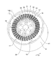
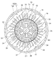
- FIG. 1 is a cross-sectional view showing a motor 100 according to the first embodiment.
- the motor 100 is a brushless DC motor, and is used for a compressor 500 (FIG. 20) described later.
- the motor 100 is a reluctance motor (more specifically, a synchronous reluctance motor) that generates a driving force by a reluctance torque without using a permanent magnet.
- the motor 100 includes a stator 1 and a rotor 3 that is rotatably provided inside the stator 1. An air gap is provided between the stator 1 and the rotor 3.
- the stator 1 is incorporated on the inner peripheral surface 41 side of the cylindrical shell 4 of the compressor 500.
- the rotor 3 has a cylindrical rotor core 30.
- the rotor core 30 is formed by stacking laminated steel plates (magnetic steel plates) having a thickness of 0.25 to 0.5 mm, for example, in the direction of the rotation axis and fixed by caulking or the like.
- a circular shaft hole 37 is formed at the radial center of the rotor core 30.
- a shaft 38 that is a rotating shaft is fixed to the shaft hole 37 by press-fitting.
- An axis C ⁇ b> 1 that is the central axis of the shaft 38 forms the rotation axis of the rotor 3.
- the direction of the axis C1 of the shaft 38 is referred to as “axial direction”.
- the circumferential direction around the axis C1 (indicated by an arrow R1 in FIG. 1 and the like) is referred to as “circumferential direction”.
- a radial direction centered on the axis C1 is referred to as a “radial direction”.
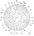
- FIG. 2 is a cross-sectional view showing the rotor 3.
- the rotor 3 has an annular outer peripheral surface 30a (outer periphery) extending in the circumferential direction, and has six magnetic poles in the circumferential direction.
- the number of poles P of the rotor 3 is 6.
- the symbols P1, P2, P3, P4, P5, and P6 are attached to the six magnetic poles.
- the number of poles P is not limited to 6, but may be 2 or more.
- the center position in the circumferential direction of each magnetic pole is the pole center.
- there is a gap (indicated by a symbol M in FIG. 2).
- a first slit 31 is formed along the outer periphery of the rotor core 30.
- a second slit 32 is formed on the radially inner side of the first slit 31.
- the first slit 31 and the second slit 32 correspond to one magnetic pole. In other words, each of the six magnetic poles has the first slit 31 and the second slit 32.
- the first slit 31 and the second slit 32 are also referred to as a flux barrier.
- the first slit 31 has an arc shape in which a central portion 31a in the circumferential direction protrudes radially inward from both end portions 31b in the circumferential direction.
- the second slit 32 has a circular arc shape in which a central portion 32a in the circumferential direction protrudes radially inward from both end portions 32b in the circumferential direction.
- the central portion 31a of the first slit 31 and the central portion 32a of the second slit 32 are on the same axis (radial axis) passing through the axis C1. is there.
- This axis corresponds to the q-axis (that is, the center line of the magnetic pole).
- the radial axis passing between the magnetic poles adjacent in the circumferential direction corresponds to the d-axis (that is, the center line between the poles).
- FIG. 3 is an enlarged view showing a portion including one magnetic pole of the rotor core 30.
- Each of the first slits 31 has an arcuate outer peripheral side edge 311 and an inner peripheral side edge 312. From the stator 1 between the first slit 31 and the outer peripheral surface 30a of the rotor core 30 (more specifically, between the outer peripheral side edge 311 of the first slit 31 and the outer peripheral surface 30a of the rotor core 30). A region B1 through which the magnetic flux flows is formed.
- Each of the second slits 32 has an arcuate outer peripheral side edge 321 and an inner peripheral side edge 322. Between the first slit 31 and the second slit 32 (more specifically, between the inner peripheral side edge 312 of the first slit 31 and the outer peripheral side edge 321 of the second slit 32). The region B2 through which the magnetic flux from the stator 1 flows is formed.
- the first slit 31 and the second slit 32 of the rotor core 30 cause a difference between the d-axis inductance Ld and the q-axis inductance Lq, and reluctance torque is generated.
- an outer peripheral bridge that is a thin portion is formed between the end 31 b of the first slit 31 and the outer peripheral surface 30 a of the rotor core 30.
- an outer peripheral bridge that is a thin portion is formed between the end portion 32 b of the second slit 32 and the outer peripheral surface 30 a of the rotor core 30.
- the thickness of the outer bridge is, for example, the same as the thickness of one laminated steel plate.
- a circular shaft hole 37 that fits into the shaft 38 is formed in the central portion of the rotor core 30 in the radial direction.
- a groove portion 35 is formed on the outer side in the radial direction from the outer peripheral surface of the shaft hole 37.
- the groove portion 35 penetrates the rotor core 30 in the axial direction.
- the radially outer end 35 a of the groove 35 is close to the center 32 a of the second slit 32.
- the shortest distance between the end 35a of the groove 35 and the second slit 32 is, for example, the same as the thickness of one laminated steel plate.
- the rotor core 30 has the same number of grooves 35 as the number of poles P formed radially.
- the number of poles P is 6, six groove portions 35 are formed.
- the circumferential position of each groove 35 corresponds to each magnetic pole.
- the center line of the groove part 35 (the radial line that defines the circumferential center of the groove part 35) coincides with the center line of the magnetic pole.
- the groove part 35 constitutes a refrigerant passage through which the refrigerant flows.
- the groove part 35 is formed continuously with the shaft hole 37, it may be spaced apart from the shaft hole 37 radially outward.
- the number of the groove portions 35 is not limited to the same number as the number of poles P, and may be one or more.
- the stator 1 includes a stator core 10 and a winding 2 (FIG. 5) wound around the stator core 10 by wave winding.
- the stator core 10 is formed by, for example, laminating steel sheets (magnetic steel sheets) having a thickness of 0.25 to 0.5 mm, which are laminated in the axial direction and fixed by a caulking portion 17.
- the stator core 10 includes an annular yoke portion 11 extending in the circumferential direction and a plurality of teeth 12 extending radially inward from the yoke portion 11.
- a slot 13 is formed between the teeth 12 adjacent in the circumferential direction.
- the slot 13 is a portion that accommodates the winding 2 wound around the tooth 12 and extends in the radial direction.
- the number of teeth 12 and the number of slots 13 are the same as each other, and in the example shown in FIG. That is, six slots 13 correspond to one magnetic pole of the rotor 3.
- the number of slots S is 3n (n is a natural number) times the number of poles P. Therefore, the ratio (ratio) S / P of the slot number S to the pole number P is, for example, 3, 6, 9, 12, 15 or the like.
- a notch 16 is formed on the outer peripheral surface 18 of the stator core 10.
- the notch 16 is a cylindrical outer peripheral surface 18 that is notched with a plane parallel to the axis C ⁇ b> 1, and extends across the entire axial direction of the stator core 10.
- the notch portion 16 is formed at a plurality of locations in the circumferential direction in the yoke portion 11. Here, six notches 16 having the same number as the number of poles P are arranged at equal intervals in the circumferential direction.
- the notch 16 constitutes a refrigerant passage that allows the refrigerant to pass in the axial direction between the inner peripheral surface 41 of the shell 4.
- the yoke portion 11 is formed with a crimping portion 17 that fixes the laminated steel plates constituting the stator core 10 to each other.
- the reason why the caulking portion 17 is formed not on the teeth 12 but on the yoke portion 11 is to prevent the flow of magnetic flux from being disturbed by the caulking portion 17.
- six crimping portions 17 having the same number as the number of poles P are formed at equal intervals in the circumferential direction.
- the caulking portion 17 is formed at a position corresponding to the central portion in the circumferential direction of the notch portion 16.
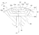
- FIG. 4 is a schematic view showing a part of the stator 1 in an enlarged manner.
- the width (the length in the circumferential direction) of the tooth 12 becomes narrower as the tip 12a of the tooth 12 is approached. That is, the width W1 at the tip 12a (the radially inner end) of the tooth 12 is narrower than the width W2 at the root 12b (the radially outer end) of the tooth 12.
- the length of the teeth 12 in the radial direction (that is, the distance from the root portion 12b to the tip portion 12a) is H1.
- H1 is also the length of the slot 13.
- the distance (yoke width) from the root portion 12b of the tooth 12 to the outer peripheral surface 18 of the yoke portion 11 is defined as H2.
- the yoke width H2 is the width of a magnetic path that flows in the circumferential direction in the yoke portion 11.
- the windings 2 are arranged in a line.
- the circumferential width Ws of the slot 13 is set to such a width that the windings 2 are arranged in a line. That is, the slot 13 has a rectangular shape having a circumferential width Ws and a radial length H1.
- the radially inner end of the slot 13 is an opening 13a into which the winding 2 is inserted, and the radially outer end is a terminal end 13b.
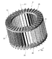
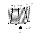
- FIG. 5 is a perspective view showing the motor 100 in which the winding 2 is wound around the stator core 10.
- the winding 2 is wound around 36 teeth 12 (FIG. 1) of the stator core 10 by wave winding. Since the coil
- the winding 2 is wound by wave winding, the amount of projection of the winding 2 from the stator core 10 in the axial direction is small compared to the case of winding by concentric winding.
- the axial length of the stator core 10 and the rotor core 30 can be increased by the amount of the axial protrusion of the winding 2 being small.
- the part (part inserted in the slot 13) other than a coil end part can be lengthened among the full length of the coil
- the winding 2 is a conductor (for example, copper) formed with a corrosion-resistant film such as a polyesterimide or polyamideimide film.
- winding 2 is for contacting the refrigerant
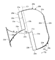
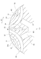
- FIG. 6 is a schematic diagram showing only the winding 2 wound by wave winding.
- Winding 2 includes linear portion 22 inserted into slot 13 (FIG. 1), coil end portion 21 extending in the circumferential direction at one axial end surface of rotor core 30, and the other axial end surface of rotor core 30. And a coil end portion 23 extending in the circumferential direction.
- FIG. 7 is an enlarged view showing a part of the coil end portion 21 of the winding 2.
- nine winding portions 20 are wound at the same radial winding position (for example, the innermost circumferential position) while shifting the circumferential position by one slot.
- Three of the nine winding portions 20 wound on the innermost periphery are referred to as winding portions 20a, 20b, and 20c.
- FIG. 8 is a schematic view showing one winding portion 20a.
- the winding portion 20a includes two coil end portions 21a, four linear portions 22a, and two coil end portions 23a.
- the winding portion 20 a is wound so as to straddle the nine teeth 12. That is, the straight portion 22a of the winding portion 20a is inserted into every nine slots 13.
- the coil end portion 21a extends so as to connect one axial end (the upper end in FIG. 8) of the linear portion 22a, and the coil end portion 23a connects the other axial end (the lower end in FIG. 8) of the linear portion 22a. It extends to connect.
- the coil end portions 21a and the coil end portions 23a are alternately arranged in the circumferential direction around the axis C1.
- a nose portion 25a that is displaced in the radial direction by a displacement amount E1 is provided at the center portion in the circumferential direction of the coil end portion 21a.
- the coil end portion 21a extends in the circumferential direction around the axis C1, and is displaced radially inward by the displacement amount E1 at the nose portion 25a. It extends in the direction indicated by.
- a nose portion 26a that is displaced by a displacement amount E1 in the radial direction is provided at the center portion in the circumferential direction of the coil end portion 23a.
- the coil end portion 23a extends in the circumferential direction around the axis C1, and is displaced radially outward by the nose portion 26a by the displacement amount E1. It extends in the direction indicated by.
- FIG. 9 is a schematic diagram showing two winding portions 20a and 20b. Similar to the winding portion 20a, the winding portion 20b has two coil end portions 21b, four linear portions 22b, and two coil end portions 23b.
- the linear portion 22b of the winding portion 20b is at a position shifted by one slot clockwise with respect to the axis C1 with respect to the linear portion 22a of the winding portion 20a.
- Nose portions 25b and 26b are respectively formed at the center portions in the circumferential direction of the coil end portions 21b and 23b, similarly to the nose portions 25a and 26a of the coil end portions 21a and 23a.
- the coil end portions 21a and 21b of the winding portions 20a and 20b overlap in the axial direction and extend in the circumferential direction, and the top and bottom (axial positional relationship) are reversed through the nose portions 25a and 25b.
- the coil end portions 23a and 23b of the winding portions 20a and 20b overlap in the axial direction and extend in the circumferential direction, and are reversed upside down via the nose portions 26a and 26b. Therefore, the straight portions 22a and 22b of the winding portions 20a and 20b can be inserted into the adjacent slots 13 (FIG. 1) without interfering with each other.
- FIG. 9 shows only two winding portions 20a and 20b, but a total of nine winding portions 20a and 20b including these at the same radial winding position (for example, the innermost circumferential position) as the winding portions 20a and 20b.
- Winding portion 20 is wound. That is, the straight portions 22 of the winding 2 are inserted into all 36 slots 13 of the stator core 10.
- FIG. 10 is a schematic diagram showing a total of eight winding portions 20 inserted into the same slot 13 as the winding portion 20a shown in FIG.
- the eight winding portions 20 are wound at equal intervals in the radial direction.
- the winding portion 20 is wound with a shift of one slot in the circumferential direction (FIG. 9) and also wound in the radial direction, whereby the wave winding 2 shown in FIG. 6 is formed. .
- the number of winding portions 20 inserted into one slot 13 and the number of teeth 12 spanned by the winding portion 20 are not limited to the examples shown in FIGS. It can be arbitrarily set according to the number of slots S.
- FIG. 11 is a diagram illustrating the analysis result of the magnetic flux distribution in the motor 100 when the groove portion 35 is not provided in the rotor core 30.
- a current is passed through the winding 2 (not shown in FIG. 11) in the slot 13 of the stator 1
- the magnetic flux generated by this winding current is distributed as shown in FIG.
- the magnetic flux flows through a region B ⁇ b> 1 on the outer peripheral side of the first slit 31 and a band-shaped region B ⁇ b> 2 between the first slit 31 and the second slit 32.
- the magnetic flux flowing in the inner peripheral region B3 surrounded by the second slits 32 of the six magnetic poles is very small.
- FIG. 12 is a diagram showing an analysis result of the magnetic flux distribution in the motor 100 when the groove portion 35 is provided in the rotor core 30.
- the groove 35 is formed in the inner peripheral side region B3 of the rotor core 30, and only a slight magnetic flux flows through the inner peripheral side region B3. Therefore, the groove portion 35 does not hinder the flow of magnetic flux in the rotor core 30 and does not affect the magnetic characteristics of the motor 100.
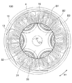
- FIG. 13 is a cross-sectional view showing a motor 100D of a comparative example, in a cross section orthogonal to the axis C1.
- the motor 100D of the comparative example has a stator 1D and a rotor 3D.
- Stator 1D has stator core 10D and winding 2D wound around stator core 10D.
- the stator core 10D has an annular yoke portion 11D and 18 teeth 12D protruding radially inward from the yoke portion 11D.
- a slot 13D is formed between the teeth 12D adjacent in the circumferential direction.
- a winding 2D is wound around the teeth 12D in a concentric manner.
- the rotor 3D is configured in the same manner as the rotor 3 of the first embodiment except that the rotor 3D is not provided.
- the coil end portion is large. Therefore, in order to store the motor 100D in a limited space in the compressor, it is necessary to reduce the axial lengths of the stator core 10D and the rotor core 30.
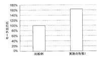
- FIG. 14 is a graph showing a comparison between the output of the motor 100 (FIG. 1) of the first embodiment and the output of the motor 100D (FIG. 13) of the comparative example.
- the motor output of the motor 100 of the first embodiment and the motor 100D of the comparative example are compared with the same size (size in the axial direction and radial direction) of the entire motor.
- the winding 2 wound by the wave winding has a coil end portion smaller than the winding 2 wound by the concentric winding. Therefore, in the motor 100 of the first embodiment, the axial lengths of the stator core 10 and the rotor core 30 can be increased and inserted into the slot 13 of the winding 2 as compared with the comparative motor 100D having the same dimensions. The length (the length that contributes to the generation of driving force) can be increased.
- the torque constant can be increased by increasing the axial length of the stator core 10 and the rotor core 30 and the length that contributes to the generation of the driving force of the winding 2. Therefore, when the same current is passed through the winding 2, the motor 100 of the first embodiment can generate a higher output than the motor 100D of the comparative example. In the analysis result shown in FIG. 14, the motor 100 of the first embodiment generates an output that is 60% higher than the motor 100D of the comparative example.
- the motor 100 according to the first embodiment can generate a high output even though it is a reluctance motor that does not use a permanent magnet.
- first slit 31 and second slit 32 are formed in each magnetic pole
- three or more slits may be formed in each magnetic pole.
- the outermost slit of each magnetic pole is referred to as a first slit
- the innermost slit is referred to as a second slit.
- the motor 100 according to the first embodiment of the present invention is a reluctance motor having the first slit 31 and the second slit 32 in each magnetic pole of the rotor 3. 2 is wound by wave winding, and a notch 16 (refrigerant passage) is formed for circulating the refrigerant in the axial direction.
- the coil end portion is small, so that it contributes to the axial length of the stator core 10 and the rotor core 30 and the generation of the driving force of the winding 2 without enlarging the entire motor 100.
- the length to do can be lengthened. As a result, a high output can be obtained even with a reluctance motor having no permanent magnet.
- the winding 2 is wound in a wave winding, and the protrusion to the outside in the radial direction is small, the flow of the refrigerant passing through the notch portion 16 is not hindered by the winding 2, and a sufficient flow rate of the refrigerant is ensured. can do. That is, it is possible to flow a refrigerant having a flow rate corresponding to the improvement in the output of the motor 100.
- the groove portion 35 penetrating the rotor core 30 in the radial direction is provided on the radially outer side of the shaft hole 37 of the rotor core 30, the flow rate of the refrigerant can be increased without hindering the flow of magnetic flux in the rotor core 30.
- the groove portion 35 is formed continuously with the shaft hole 37, the laminated steel plate can be easily processed, and the area of the groove portion 35 (that is, the flow path area) can be secured large.
- the slits 31 and 32 have circular arc shapes in which the center portions 31a and 32a in the circumferential direction protrude radially inward from the both end portions 31b and 32b. Therefore, the slits 31 and 32 have a d-axis inductance Ld and a q-axis inductance Lq. A difference can be produced and a reluctance torque can be produced.
- FIG. 15 is a cross-sectional view taken along a plane orthogonal to the axis C1, showing the configuration of the motor 100A according to the second embodiment.
- the motor 100A has a stator 1 and a rotor 3A.
- the stator 1 of the motor 100A has the same configuration as the stator 1 of the motor 100 of the first embodiment. That is, the stator core 10 of the stator 1 includes a yoke portion 11 and a tooth 12, the winding 2 is wound around the tooth 12 by a wave winding, and the yoke portion 11 has a notch portion 16 through which refrigerant flows in the axial direction. (Refrigerant passage) is formed.
- the rotor 3A of the motor 100A is obtained by providing a caulking portion 33 and a rivet hole (through hole) 34 to the rotor 3 of the motor 100 of the first embodiment.
- the number of crimping portions 33 and the number of rivet holes 34 are both the same as the number of poles P.
- the number of poles P is 6, the number of crimping portions 33 and the number of rivet holes 34 are both six.
- FIG. 16 is an enlarged view showing a part of the rotor 3A.
- the caulking part 33 of the rotor 3 fixes the laminated steel plates constituting the rotor core 30 to each other.
- the caulking portion 33 is formed in the inner peripheral side region B ⁇ b> 3 surrounded by the second slit 32 of each magnetic pole in the rotor core 30. Further, the caulking portion 33 is formed between the electrodes. More specifically, the crimping portion 33 is formed at a position sandwiched between two second slits 32 adjacent in the circumferential direction.
- the rivet hole 34 of the rotor 3 is formed in the inner peripheral side region B3 surrounded by the second slit 32 of each magnetic pole in the rotor core 30 like the caulking portion 33.
- the rivet hole 34 is formed between the poles and is located on the radially inner side of the crimping portion 33.
- the caulking portion 33 and the rivet hole 34 are provided in the rotor core 30. Does not block the flow of magnetic flux.
- the occupied area of the gap portions (slits 31 and 32) of the rotor core 30 is larger than that in the permanent magnet embedded motor, and the area where the caulking portion 33 can be formed is small.
- the rivet hole 34 through which the rivet is inserted occupies a larger area than the caulking portion 17. Therefore, in the second embodiment, the rivet hole 34 is formed on the inner side in the radial direction than the caulking portion 33.
- the caulking portion 33 and the rivet hole 34 are formed between all the six poles, the weight balance in the circumferential direction of the rotor core 30 is improved.
- six crimping portions 33 and six rivet holes 34 are formed, but it is sufficient that at least one of them is formed.
- both the crimping portion 33 and the rivet hole 34 are formed in the rotor core 30, but only the crimping portion 33 may be formed, or only the rivet hole 34 may be formed. Further, the rivet hole 34 may be used as a through hole through which the refrigerant passes in the axial direction.
- first slit 31 and second slit 32 are formed in each magnetic pole, but three or more slits may be formed.
- the caulking portion 33 and the rivet hole 34 may be formed in a region surrounded by the innermost slit (referred to as a second slit) of each magnetic pole.
- the caulking portion 33 is formed in the inner peripheral side region B3 surrounded by the second slit 32 of each magnetic pole of the rotor core 30, so that the flow of magnetic flux in the rotor core 30
- the caulking portion 33 is provided so as not to hinder, and the laminated element of the rotor core 30 can be firmly fixed.
- a rivet hole (through hole) 34 is formed on the inner side in the radial direction of the caulking portion 33, the rivet hole 34 is provided so as not to disturb the flow of magnetic flux in the rotor core 30, thereby further strengthening the laminated elements of the rotor core 30. Can be fixed.
- the crimping portion 33 and the rivet hole 34 are formed between the poles, the limited space of the inner peripheral side region B3 of the rotor core 30 can be used effectively. Since the crimping portion 33 and the rivet hole 34 are provided between all the poles, the weight balance in the circumferential direction of the rotor core 30 is improved.
- FIG. 17 is a cross-sectional view taken along a plane orthogonal to the axis C1, showing the configuration of the motor 100B according to the third embodiment.
- the motor 100B has a stator 1 and a rotor 3B.
- the stator 1 of the motor 100B has the same configuration as the stator 1 of the motor 100 of the first embodiment. That is, the stator core 10 of the stator 1 includes a yoke portion 11 and a tooth 12, the winding 2 is wound around the tooth 12 by a wave winding, and the yoke portion 11 has a notch portion 16 through which refrigerant flows in the axial direction. (Refrigerant passage) is formed.
- the rotor 3B of the motor 100B has a slit shape different from that of the rotor 3 of the motor 100 of the first embodiment.
- the rotor 3 ⁇ / b> B of the second embodiment includes a first slit 51 formed along the outer peripheral surface 30 a of the rotor core 30 and a second slit 52 formed on the radially inner side of the first slit 51.
- the first slit 51 and the second slit 52 correspond to one magnetic pole. In other words, each of the six magnetic poles has the first slit 51 and the second slit 52.
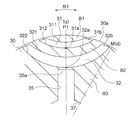
- FIG. 18 is an enlarged view showing a part of the rotor 3B.
- the first slit 51 includes a first portion 51b that includes a central portion 51a in the circumferential direction and extends linearly, and a straight line from each circumferential end of the first portion 51b toward the outer periphery of the rotor core 30. And a pair of second portions 51c extending in a shape.
- the first portion 51b extends in a direction orthogonal to the radial straight line (magnetic pole center line) passing through the central portion 51a.
- the pair of second portions 51c extend symmetrically with respect to a straight line in the radial direction passing through the central portion 51a so that the distance between the second portions 51c increases toward the outer side in the radial direction.
- the second slit 52 includes a first portion 52b that extends in a straight line including the central portion 52a in the circumferential direction, and a straight line from each circumferential end of the first portion 52b toward the outer periphery of the rotor core 30. And a pair of second portions 52c extending in a shape.
- the first portion 52b extends in a direction orthogonal to the radial straight line (magnetic pole center line) passing through the central portion 52a.
- the pair of second portions 52c extend symmetrically with respect to a radial straight line passing through the central portion 52a so that the distance between the second portions 52c increases toward the outer side in the radial direction.
- a region B1 through which the magnetic flux from the stator 1 flows is formed on the outer peripheral side of the first slit 51. Between the 1st slit 51 and the 2nd slit 52, the strip
- two slits are formed in each magnetic pole of the rotor 3B, but three or more slits may be formed.
- the configurations of the shaft hole 37 and the groove 35 of the rotor core 30 are the same as those in the first embodiment. Further, the caulking portion 33 and the rivet hole 34 described in the second embodiment may be formed in the inner peripheral region B3 of the rotor core 30.
- the reluctance motor has the first slit 51 and the second slit 52 in each magnetic pole of the rotor 3B, and the winding 2 is wound around the stator core 10. And a notch 16 (refrigerant passage) is formed through which the refrigerant flows in the axial direction. Therefore, as in the first embodiment, a high output can be obtained without enlarging the entire motor 100B. In addition, since the winding 2 is wound in a wave manner and there is little overhanging outward in the radial direction, a sufficient flow rate of the refrigerant passing through the notch portion 16 can be ensured.
- the groove portion 35 penetrating the rotor core 30 in the radial direction is provided on the radially outer side of the shaft hole 37 of the rotor core 30, the flow rate of the refrigerant can be increased without hindering the flow of magnetic flux in the rotor core 30.
- FIG. 19 is a cross-sectional view taken along a plane orthogonal to the axis C1, showing the configuration of the motor 100C according to the third embodiment.
- the motor 100 ⁇ / b> C includes a stator 1 ⁇ / b> C and a rotor 3.
- the stator 1C of the motor 100C has a stator core 10 and a winding 2.
- the stator core 10 has a yoke portion 11 and a tooth 12, and the winding 2 is wound around the tooth 12 by wave winding.
- a through hole 15 (refrigerant passage) through which the refrigerant flows in the axial direction is formed in the yoke portion 11 instead of the notch portion 16.
- through holes 15 having the same number as the number of poles P are formed at equal intervals in the circumferential direction.
- the through hole 15 is located on a radial axis passing through the center position in the circumferential direction of the tooth 12.
- the through holes 15 are preferably formed alternately with the caulking portions 17 of the stator core 10 in the circumferential direction.
- the notch portion 16 (FIG. 1) described in the first embodiment may be formed in the yoke portion 11.
- the number of through holes 15 is not limited to the same number as the number of poles P, and may be one or more.
- the rotor 3 of the motor 100C has the same configuration as the rotor 3 of the first embodiment.
- the caulking portion 33 and the rivet hole 34 may be formed in the rotor 3 as described in the second embodiment, and the shapes of the slits 51 and 52 described in the third embodiment may be employed.
- the through hole 15 through which the refrigerant passes is formed in the yoke portion 11 of the stator 1C, and the winding 2 is wound in the tooth 12 by the wave winding.
- the flow of the refrigerant passing through the hole 15 is not hindered by the winding 2, and a sufficient flow rate of the refrigerant can be ensured.
- both the through-hole 15 and the notch part 16 are provided in the yoke part 11 of the stator 1C, the flow rate of the refrigerant can be further increased.
- FIG. 20 is a cross-sectional view showing a configuration of a compressor (scroll compressor) 500 using the motor 100 of the first embodiment described above.
- the compressor 500 is a scroll compressor, and in a sealed container 502, a compression mechanism 510, a motor 100 that drives the compression mechanism 510, a main shaft 501 that connects the compression mechanism 510 and the motor 100, and compression of the main shaft 501
- a subframe 503 that supports the opposite end (subshaft portion) of the mechanism 510 and a lubricating oil 504 that is stored in a sump 505 at the bottom of the sealed container 502 are provided.
- the heel compression mechanism 510 includes a fixed scroll 511 and a swing scroll 512 attached to the main shaft 501. Each of the fixed scroll 511 and the swing scroll 512 has a spiral portion, and a spiral compression chamber 516 is formed therebetween.
- the compression mechanism 510 further includes an Oldham ring 513 that restricts the rotation of the swing scroll 512 to swing the swing scroll 512, a compliant frame 514 to which the swing scroll 512 is attached, and a guide frame that supports these. 515.
- a suction pipe 506 penetrating the sealed container 502 is press-fitted into the heel fixed scroll 511.
- a discharge pipe 507 that discharges high-pressure refrigerant gas discharged from the discharge port 511a of the fixed scroll 511 to the outside through the sealed container 502 is provided.
- the sealed container 502 has a cylindrical shell 4 (FIG. 1), and the motor 100 of the first embodiment is attached to the inner peripheral side of the shell 4.
- a glass terminal 508 for electrically connecting the stator 1 of the motor 100 and the drive circuit is fixed to the sealed container 502 by welding.
- the main shaft 501 is the shaft 38 (FIG. 1) of the motor 100.
- the operation of the compressor 500 is as follows.
- the main shaft 501 (shaft 38) rotates together with the rotor 3.
- the swing scroll 512 swings, and the volume of the compression chamber 516 between the fixed scroll 511 and the swing scroll 512 is changed.
- the refrigerant gas is sucked into the compression chamber 516 from the suction pipe 506 and compressed.
- the high-pressure refrigerant gas compressed in the compression chamber 516 is discharged from the discharge port 511a of the fixed scroll 511 into the sealed container 502 and discharged from the discharge pipe 507 to the outside. Further, a part of the refrigerant gas discharged from the compression chamber 516 into the sealed container 502 passes through the notch portion 16 (FIG. 1) of the stator 1 to cool the motor 100 and the lubricating oil 504.
- the motor 100 according to the first embodiment generates a high torque and has a low manufacturing cost. Therefore, the output of the compressor 500 can be increased and the manufacturing cost can be reduced.
- the compressor 500 may use the motors 100A to 100C described in Embodiments 2 to 4 instead of the motor 100.
- the scroll compressor has been described here as an example of the compressor, the motors 100 to 100C of the first to fourth embodiments may be applied to a compressor other than the scroll compressor.
- FIG. 21 is a diagram showing the configuration of the air conditioning apparatus 400.
- An air conditioner 400 shown in FIG. 21 includes a compressor 401, a condenser 402, a throttle device (decompression device) 403, and an evaporator 404.
- the compressor 401, the condenser 402, the expansion device 403, and the evaporator 404 are connected by a refrigerant pipe 407 to constitute a refrigeration cycle. That is, the refrigerant circulates in the order of the compressor 401, the condenser 402, the expansion device 403, and the evaporator 404.
- the compressor 401, the condenser 402, and the expansion device 403 are provided in the outdoor unit 410.
- the compressor 401 includes the compressor 500 shown in FIG.
- the outdoor unit 410 is provided with an outdoor fan 405 that supplies outdoor air to the condenser 402.
- the evaporator 404 is provided in the indoor unit 420.
- the indoor unit 420 is provided with an indoor blower 406 that supplies indoor air to the evaporator 404.
- the operation of the air conditioner 400 is as follows.
- the compressor 401 compresses and sends out the sucked refrigerant.
- the condenser 402 exchanges heat between the refrigerant flowing in from the compressor 401 and the outdoor air, condenses and liquefies the refrigerant, and sends it out to the refrigerant pipe 407.
- the outdoor blower 405 supplies outdoor air to the condenser 402.
- the expansion device 403 adjusts the pressure and the like of the refrigerant flowing through the refrigerant pipe 407 by changing the opening degree.
- the evaporator 404 exchanges heat between the refrigerant in the low pressure state by the expansion device 403 and the indoor air, causes the refrigerant to evaporate (vaporize) the heat of the air, and sends it to the refrigerant pipe 407.
- the indoor fan 406 supplies indoor air to the evaporator 404. Thereby, the cold air from which heat has been removed by the evaporator 404 is supplied to the room.
- the motors 100 to 100C described in the first to fourth embodiments are applied to the compressor 401 (the compressor 500 in FIG. 20), the air conditioning capability of the air conditioner 400 is increased and the manufacturing cost is reduced. Can do.
- compressor 500 to which the motors 100 to 100C of the first to fourth embodiments are applied is not limited to the air conditioner 400 shown in FIG. 21, but may be used for other types of air conditioners.
- stator core 11 yoke part, 12 teeth, 12a tip, 12b root part, 13 Slot, 15 through hole, 16 notch, 17 crimping part, 18 outer peripheral surface, 20, 20a, 20b, 20c winding part, 30 rotor core, 31 1st slit, 31a center, 31b end, 32 2nd Slit, 32a center part, 32b end part, 33 crimping part, 34 rivet hole, 35 groove part, 37 shaft hole, 38 shaft, 51 first slit, 51a center part, 51b first part, 51c second part , 52 Second slit 52a central part, 52b first part, 52c second part, 100, 100A, 100B, 100C motor, 400 air conditioner, 401 outdoor unit, 402 indoor unit, 403 refrigerant piping, 405 blower, 406 blade, 500 compression Machine (scroll compressor),
Abstract
Description
<モータの構成>
本発明の実施の形態1について説明する。図1は、実施の形態1のモータ100を示す断面図である。このモータ100は、ブラシレスDCモータであり、後述する圧縮機500(図20)に用いられる。また、このモータ100は、永久磁石を用いずに、リラクタンストルクによって駆動力を発生するリラクタンスモータ(より具体的には、同期リラクタンスモータ)である。
<Configuration of motor>
図2は、ロータ3を示す断面図である。ロータ3は、周方向に延在する環状の外周面30a(外周)を有し、周方向に6個の磁極を有する。言い換えると、ロータ3の極数Pは、6である。図2では、6個の磁極に、符号P1,P2,P3,P4,P5,P6を付している。但し、極数Pは6に限らず、2以上であればよい。各磁極の周方向の中心位置は、極中心となる。また、周方向に隣り合う任意の磁極の間は、極間(図2に符号Mで示す)となる。 <Configuration of rotor>
FIG. 2 is a cross-sectional view showing the
図1に戻り、ステータ1は、ステータコア10と、ステータコア10に波巻で巻かれた巻線2(図5)とを有する。ステータコア10は、例えば厚さ0.25~0.5mmの積層鋼板(電磁鋼板)を軸方向に積層し、カシメ部17により固定したものである。 <Structure of stator>
Returning to FIG. 1, the
次に、巻線2について説明する。図5は、ステータコア10に巻線2を巻き付けたモータ100を示す斜視図である。巻線2は、ステータコア10の36個のティース12(図1)に、波巻で巻かれる。巻線2は、波巻で巻かれているため、ティース12から径方向外側への突出量が少ない。そのため、巻線2は、切欠き部16を通過する冷媒の流れの妨げにならない。 <Configuration of winding>
Next, the winding 2 will be described. FIG. 5 is a perspective view showing the
図13は、比較例のモータ100Dを示す、軸線C1に直交する断面における断面図である。比較例のモータ100Dは、ステータ1Dとロータ3Dとを有する。ステータ1Dは、ステータコア10Dと、ステータコア10Dに巻かれた巻線2Dとを有する。ステータコア10Dは、環状のヨーク部11Dと、ヨーク部11Dから径方向内側に突出する18個のティース12Dとを有する。周方向に隣り合うティース12Dの間には、スロット13Dが形成されている。ティース12Dには、巻線2Dが、同心巻で巻かれている。ロータ3Dは、溝部35を有さない点を除き、実施の形態1のロータ3と同様に構成されている。 <Comparative example>
FIG. 13 is a cross-sectional view showing a
次に、この実施の形態1によるモータ出力の向上効果について説明する。図14は、実施の形態1のモータ100(図1)の出力と、比較例のモータ100D(図13)の出力とを比較して示すグラフである。ここでは、実施の形態1のモータ100と比較例のモータ100Dについて、モータ全体の大きさ(軸方向および径方向における寸法)を同一として、モータ出力を比較している。 <Improvement of motor output>
Next, the effect of improving the motor output according to the first embodiment will be described. FIG. 14 is a graph showing a comparison between the output of the motor 100 (FIG. 1) of the first embodiment and the output of the
以上説明したように、本発明の実施の形態1のモータ100は、ロータ3の各磁極に第1のスリット31と第2のスリット32とを有するリラクタンスモータであって、ステータコア10には巻線2が波巻で巻かれ、また冷媒を軸方向に流通させる切欠き部16(冷媒通路)が形成されている。 <Effect of Embodiment>
As described above, the
次に、本発明の実施の形態2について説明する。図15は、実施の形態2のモータ100Aの構成を示す、軸線C1に直交する面における断面図である。モータ100Aは、ステータ1と、ロータ3Aとを有している。
Next, a second embodiment of the present invention will be described. FIG. 15 is a cross-sectional view taken along a plane orthogonal to the axis C1, showing the configuration of the
次に、本発明の実施の形態3について説明する。図17は、実施の形態3のモータ100Bの構成を示す、軸線C1に直交する面における断面図である。モータ100Bは、ステータ1と、ロータ3Bとを有している。
Next, a third embodiment of the present invention will be described. FIG. 17 is a cross-sectional view taken along a plane orthogonal to the axis C1, showing the configuration of the
次に、本発明の実施の形態4について説明する。図19は、実施の形態3のモータ100Cの構成を示す、軸線C1に直交する面における断面図である。モータ100Cは、ステータ1Cと、ロータ3とを有している。
Next, a fourth embodiment of the present invention will be described. FIG. 19 is a cross-sectional view taken along a plane orthogonal to the axis C1, showing the configuration of the
次に、上述した実施の形態1のモータ100を用いた圧縮機について説明する。図20は、上述した実施の形態1のモータ100を用いた圧縮機(スクロール圧縮機)500の構成を示す断面図である。 <Compressor>
Next, a compressor using the
次に、図20に示した圧縮機500を有する空気調和装置(冷凍サイクル装置)について説明する。図21は、空気調和装置400の構成を示す図である。図21に示した空気調和装置400は、圧縮機401と、凝縮器402と、絞り装置(減圧装置)403と、蒸発器404とを備えている。圧縮機401、凝縮器402、絞り装置403および蒸発器404は、冷媒配管407によって連結されて冷凍サイクルを構成している。すなわち、圧縮機401、凝縮器402、絞り装置403および蒸発器404の順に、冷媒が循環する。 <Air conditioning device>
Next, an air conditioner (refrigeration cycle apparatus) having the
Claims (18)
- 圧縮機に用いられるリラクタンスモータであって、
軸線を中心とする環状の外周を有するロータコアを有し、前記外周に沿って複数の磁極を有し、永久磁石を有さないロータと、
前記軸線を中心とする径方向において前記ロータを外側から囲むステータコアと、前記ステータコアに波巻で巻かれた巻線とを有するステータと
を備え、
前記複数の磁極は、いずれも、前記ロータコアに形成された第1のスリットと、前記第1のスリットの前記径方向の内側に形成された第2のスリットとを有し、
前記ステータコアは、冷媒を前記軸線の方向に流通させる冷媒通路を有する
リラクタンスモータ。 A reluctance motor used in a compressor,
A rotor core having an annular outer periphery centered on an axis, a plurality of magnetic poles along the outer periphery, and a rotor having no permanent magnet;
A stator core that surrounds the rotor from the outside in a radial direction centered on the axis, and a stator having a winding wound in a wave winding around the stator core,
Each of the plurality of magnetic poles includes a first slit formed in the rotor core and a second slit formed inside the radial direction of the first slit,
The stator core is a reluctance motor having a refrigerant passage through which refrigerant flows in the direction of the axis. - 前記ロータコアは、前記径方向の中心に形成されたシャフト孔と、前記シャフト孔の前記径方向の外側に形成された溝部とを有し、
前記溝部は、前記ロータコアを前記軸線の方向に貫通する
請求項1に記載のリラクタンスモータ。 The rotor core has a shaft hole formed at the center in the radial direction, and a groove portion formed on the outer side in the radial direction of the shaft hole,
The reluctance motor according to claim 1, wherein the groove portion penetrates the rotor core in a direction of the axis. - 前記溝部は、前記シャフト孔に連続して形成されている
請求項2に記載のリラクタンスモータ。 The reluctance motor according to claim 2, wherein the groove portion is formed continuously with the shaft hole. - 前記ロータコアは、前記溝部を含む、前記複数の磁極の極数と同数の溝部を有する
請求項2または3に記載のリラクタンスモータ。 The reluctance motor according to claim 2, wherein the rotor core has the same number of grooves as the number of poles of the plurality of magnetic poles, including the groove. - 前記ロータコアは、前記複数の磁極のそれぞれの前記第2のスリットによって囲まれた領域に、カシメ部を有する
請求項1から4までの何れか1項に記載のリラクタンスモータ。 The reluctance motor according to any one of claims 1 to 4, wherein the rotor core has a crimping portion in a region surrounded by the second slits of each of the plurality of magnetic poles. - 前記カシメ部は、前記複数の磁極のうち、隣り合う2つの磁極の極間に位置している
請求項5に記載のリラクタンスモータ。 The reluctance motor according to claim 5, wherein the caulking portion is located between two adjacent magnetic poles among the plurality of magnetic poles. - 前記ロータコアは、前記カシメ部を含む、前記複数の磁極の極数と同数のカシメ部を有する
請求項5または6に記載のリラクタンスモータ。 The reluctance motor according to claim 5, wherein the rotor core includes caulking portions that are the same as the number of poles of the plurality of magnetic poles, including the caulking portion. - 前記ロータコアは、前記カシメ部よりも前記径方向の内側に、前記ロータコアを前記軸線の方向に貫通する貫通穴を有する
請求項5から7までの何れか1項に記載のリラクタンスモータ。 The reluctance motor according to any one of claims 5 to 7, wherein the rotor core has a through-hole penetrating the rotor core in the axial direction on the inner side in the radial direction than the caulking portion. - 前記貫通穴は、前記複数の磁極のうち、隣り合う2つの磁極の極間に位置している
請求項8に記載のリラクタンスモータ。 The reluctance motor according to claim 8, wherein the through hole is located between two adjacent magnetic poles among the plurality of magnetic poles. - 前記ロータコアは、前記貫通穴を含む、前記複数の磁極の極数と同数の貫通穴を有する
請求項8または9に記載のリラクタンスモータ。 The reluctance motor according to claim 8 or 9, wherein the rotor core has as many through holes as the number of poles of the plurality of magnetic poles including the through holes. - 前記第1のスリットおよび前記第2のスリットは、いずれも、前記軸線を中心とする周方向の中心部が前記周方向の両端部よりも前記径方向の内側に突出する円弧形状を有する
請求項1から10までの何れか1項に記載のリラクタンスモータ。 The first slit and the second slit both have an arc shape in which a central portion in the circumferential direction centering on the axis protrudes inward in the radial direction from both end portions in the circumferential direction. The reluctance motor according to any one of 1 to 10. - 前記第1のスリットおよび前記第2のスリットは、いずれも、前記軸線を中心とする周方向の中心部を含み直線状に延在する第1の部分と、前記第1の部分の前記周方向の両端部から前記ロータの前記外周に向けて直線状に延在する一対の第2の部分とを有する
請求項1から10までの何れか1項に記載のリラクタンスモータ。 Each of the first slit and the second slit includes a first portion including a central portion in the circumferential direction centered on the axis and extending linearly, and the circumferential direction of the first portion The reluctance motor according to claim 1, further comprising: a pair of second portions extending linearly from both ends of the rotor toward the outer periphery of the rotor. - 前記冷媒通路は、前記ステータコアの外周に、前記ステータコアの前記軸線の方向の全域に亘って形成された切欠き部を有する
請求項1から12までの何れか1項に記載のリラクタンスモータ。 The reluctance motor according to any one of claims 1 to 12, wherein the refrigerant passage has a notch formed on an outer periphery of the stator core over an entire region in a direction of the axis of the stator core. - 前記冷媒通路は、前記ステータコアを前記軸線の方向に貫通する貫通穴を有する
請求項1から12までの何れか1項に記載のリラクタンスモータ。 The reluctance motor according to any one of claims 1 to 12, wherein the refrigerant passage has a through hole that penetrates the stator core in the direction of the axis. - 前記巻線は、ポリエステルイミドまたはポリアミドイミドの被膜を有する
請求項1から14までの何れか1項に記載のリラクタンスモータ。 The reluctance motor according to any one of claims 1 to 14, wherein the winding has a film of polyesterimide or polyamideimide. - 請求項1から15までの何れか1項に記載のリラクタンスモータと、前記リラクタンスモータによって駆動される圧縮機構とを備えた
圧縮機。 A compressor comprising: the reluctance motor according to any one of claims 1 to 15; and a compression mechanism driven by the reluctance motor. - 前記圧縮機は、円筒状のシェルを有し、
前記ステータコアは、前記シェルの内側に嵌合する
請求項16に記載の圧縮機。 The compressor has a cylindrical shell,
The compressor according to claim 16, wherein the stator core is fitted inside the shell. - 圧縮機、凝縮器、減圧装置および蒸発器を備えた空気調和装置であって、
前記圧縮機は、請求項1から15までの何れか1項に記載のリラクタンスモータと、前記リラクタンスモータによって駆動される圧縮機構とを備える
空気調和装置。
An air conditioner comprising a compressor, a condenser, a decompression device and an evaporator,
The said compressor is provided with the reluctance motor in any one of Claim 1-15, and the compression mechanism driven by the said reluctance motor. Air conditioning apparatus.
Priority Applications (4)
| Application Number | Priority Date | Filing Date | Title |
|---|---|---|---|
| US16/603,374 US11264847B2 (en) | 2017-06-02 | 2017-06-02 | Reluctance motor, compressor, and air conditioner |
| JP2019521886A JP6789390B2 (en) | 2017-06-02 | 2017-06-02 | Reluctance motors, compressors and air conditioners |
| EP17911412.9A EP3633834B1 (en) | 2017-06-02 | 2017-06-02 | Reluctance motor, compressor, and air conditioner |
| PCT/JP2017/020536 WO2018220806A1 (en) | 2017-06-02 | 2017-06-02 | Reluctance motor, compressor, and air conditioner |
Applications Claiming Priority (1)
| Application Number | Priority Date | Filing Date | Title |
|---|---|---|---|
| PCT/JP2017/020536 WO2018220806A1 (en) | 2017-06-02 | 2017-06-02 | Reluctance motor, compressor, and air conditioner |
Publications (1)
| Publication Number | Publication Date |
|---|---|
| WO2018220806A1 true WO2018220806A1 (en) | 2018-12-06 |
Family
ID=64455865
Family Applications (1)
| Application Number | Title | Priority Date | Filing Date |
|---|---|---|---|
| PCT/JP2017/020536 WO2018220806A1 (en) | 2017-06-02 | 2017-06-02 | Reluctance motor, compressor, and air conditioner |
Country Status (4)
| Country | Link |
|---|---|
| US (1) | US11264847B2 (en) |
| EP (1) | EP3633834B1 (en) |
| JP (1) | JP6789390B2 (en) |
| WO (1) | WO2018220806A1 (en) |
Cited By (4)
| Publication number | Priority date | Publication date | Assignee | Title |
|---|---|---|---|---|
| FR3104651A1 (en) * | 2019-12-13 | 2021-06-18 | Danfoss Commercial Compressors | Scroll compressor with a synchronous reluctance motor with direct line start (DOL) |
| WO2023084676A1 (en) * | 2021-11-11 | 2023-05-19 | 三菱電機株式会社 | Reluctance motor, compressor, air conditioning device, and method for manufacturing reluctance motor |
| WO2023152891A1 (en) * | 2022-02-10 | 2023-08-17 | 三菱電機株式会社 | Reluctance motor drive device, reluctance motor unit, compressor and air conditioner |
| JP7437808B2 (en) | 2022-05-26 | 2024-02-26 | 國立宜蘭大學 | Motor rotor and its design method |
Citations (12)
| Publication number | Priority date | Publication date | Assignee | Title |
|---|---|---|---|---|
| JPS63245239A (en) * | 1987-03-31 | 1988-10-12 | Toshiba Corp | Rotor for induction motor |
| JPH10290541A (en) * | 1997-04-14 | 1998-10-27 | Sanyo Electric Co Ltd | Rotor for motor |
| JP2002153029A (en) * | 2000-11-13 | 2002-05-24 | Denso Corp | Reluctance motor |
| JP2004088852A (en) | 2002-08-23 | 2004-03-18 | Daikin Ind Ltd | Motor and compressor using the same |
| JP2009077480A (en) * | 2007-09-19 | 2009-04-09 | Mitsubishi Electric Corp | Rotary motor |
| JP2010075011A (en) * | 2008-09-22 | 2010-04-02 | Mitsubishi Electric Corp | Stator for motor, motor, and compressor |
| JP2011083066A (en) | 2009-10-02 | 2011-04-21 | Osaka Prefecture Univ | Permanent magnet assisted synchronous reluctance motor |
| JP2011147259A (en) * | 2010-01-14 | 2011-07-28 | Mitsubishi Electric Corp | Reluctance motor |
| JP2013192359A (en) | 2012-03-14 | 2013-09-26 | Mitsuba Corp | Brushless motor |
| JP2015156756A (en) * | 2014-02-20 | 2015-08-27 | 三菱電機株式会社 | Single phase induction motor, sealed compressor and refrigeration cycle system |
| WO2015132991A1 (en) * | 2014-03-05 | 2015-09-11 | 三菱電機株式会社 | Synchronous reluctance motor |
| WO2016002012A1 (en) * | 2014-07-01 | 2016-01-07 | 三菱電機株式会社 | Rotor, electric motor, compressor, and fan |
Family Cites Families (15)
| Publication number | Priority date | Publication date | Assignee | Title |
|---|---|---|---|---|
| JPS60114555U (en) * | 1984-01-06 | 1985-08-02 | 三菱電機株式会社 | Field core of rotating electric machine |
| JPH10281064A (en) * | 1997-04-02 | 1998-10-20 | Daikin Ind Ltd | Hermetic electrically driven compressor |
| TW364234B (en) | 1997-04-14 | 1999-07-11 | Sanyo Electric Co | Rotor for an electric motor |
| US6189322B1 (en) * | 1998-03-13 | 2001-02-20 | Mitsubishi Denki Kabushiki Kaisha | Refrigerant-circulating system, and refrigerant compressor and refrigeration cycle employing the refrigerant compressor |
| JP3906879B2 (en) * | 1998-03-31 | 2007-04-18 | 株式会社富士通ゼネラル | Reluctance motor |
| JP3952346B2 (en) * | 1998-05-20 | 2007-08-01 | 株式会社デンソー | Rotating electric machine and manufacturing method thereof |
| JP2006121821A (en) * | 2004-10-21 | 2006-05-11 | Honda Motor Co Ltd | Synchronous reluctance motor and electric steering device mounted with the synchronous reluctance motor |
| WO2006121225A2 (en) * | 2005-05-12 | 2006-11-16 | Lg Electronics Inc. | Rotor of synchronous reluctance motor |
| JP4815204B2 (en) * | 2005-12-01 | 2011-11-16 | アイチエレック株式会社 | Permanent magnet rotating machine and compressor |
| JP2009077582A (en) * | 2007-09-21 | 2009-04-09 | Toyota Industries Corp | Interphase insulating sheet in dynamo-electric machine, method of manufacturing interphase insulating sheet, and electric compressor |
| JP2009185722A (en) * | 2008-02-07 | 2009-08-20 | Panasonic Corp | Hermetic compressor |
| CN102099987B (en) * | 2008-08-05 | 2014-06-11 | 三菱电机株式会社 | Induction motor and enclosed compressor |
| CN102414448B (en) * | 2009-03-26 | 2015-04-15 | 江森自控科技公司 | Compressor |
| JP5235911B2 (en) | 2010-01-14 | 2013-07-10 | 三菱電機株式会社 | Reluctance motor |
| JP2015002650A (en) * | 2013-06-18 | 2015-01-05 | ダイキン工業株式会社 | Motor and compressor employing the same |
-
2017
- 2017-06-02 US US16/603,374 patent/US11264847B2/en active Active
- 2017-06-02 EP EP17911412.9A patent/EP3633834B1/en active Active
- 2017-06-02 WO PCT/JP2017/020536 patent/WO2018220806A1/en active Application Filing
- 2017-06-02 JP JP2019521886A patent/JP6789390B2/en active Active
Patent Citations (12)
| Publication number | Priority date | Publication date | Assignee | Title |
|---|---|---|---|---|
| JPS63245239A (en) * | 1987-03-31 | 1988-10-12 | Toshiba Corp | Rotor for induction motor |
| JPH10290541A (en) * | 1997-04-14 | 1998-10-27 | Sanyo Electric Co Ltd | Rotor for motor |
| JP2002153029A (en) * | 2000-11-13 | 2002-05-24 | Denso Corp | Reluctance motor |
| JP2004088852A (en) | 2002-08-23 | 2004-03-18 | Daikin Ind Ltd | Motor and compressor using the same |
| JP2009077480A (en) * | 2007-09-19 | 2009-04-09 | Mitsubishi Electric Corp | Rotary motor |
| JP2010075011A (en) * | 2008-09-22 | 2010-04-02 | Mitsubishi Electric Corp | Stator for motor, motor, and compressor |
| JP2011083066A (en) | 2009-10-02 | 2011-04-21 | Osaka Prefecture Univ | Permanent magnet assisted synchronous reluctance motor |
| JP2011147259A (en) * | 2010-01-14 | 2011-07-28 | Mitsubishi Electric Corp | Reluctance motor |
| JP2013192359A (en) | 2012-03-14 | 2013-09-26 | Mitsuba Corp | Brushless motor |
| JP2015156756A (en) * | 2014-02-20 | 2015-08-27 | 三菱電機株式会社 | Single phase induction motor, sealed compressor and refrigeration cycle system |
| WO2015132991A1 (en) * | 2014-03-05 | 2015-09-11 | 三菱電機株式会社 | Synchronous reluctance motor |
| WO2016002012A1 (en) * | 2014-07-01 | 2016-01-07 | 三菱電機株式会社 | Rotor, electric motor, compressor, and fan |
Non-Patent Citations (1)
| Title |
|---|
| See also references of EP3633834A4 |
Cited By (4)
| Publication number | Priority date | Publication date | Assignee | Title |
|---|---|---|---|---|
| FR3104651A1 (en) * | 2019-12-13 | 2021-06-18 | Danfoss Commercial Compressors | Scroll compressor with a synchronous reluctance motor with direct line start (DOL) |
| WO2023084676A1 (en) * | 2021-11-11 | 2023-05-19 | 三菱電機株式会社 | Reluctance motor, compressor, air conditioning device, and method for manufacturing reluctance motor |
| WO2023152891A1 (en) * | 2022-02-10 | 2023-08-17 | 三菱電機株式会社 | Reluctance motor drive device, reluctance motor unit, compressor and air conditioner |
| JP7437808B2 (en) | 2022-05-26 | 2024-02-26 | 國立宜蘭大學 | Motor rotor and its design method |
Also Published As
| Publication number | Publication date |
|---|---|
| EP3633834A4 (en) | 2020-05-27 |
| JP6789390B2 (en) | 2020-11-25 |
| US20200328636A1 (en) | 2020-10-15 |
| EP3633834A1 (en) | 2020-04-08 |
| US11264847B2 (en) | 2022-03-01 |
| EP3633834B1 (en) | 2021-09-01 |
| JPWO2018220806A1 (en) | 2019-11-07 |
Similar Documents
| Publication | Publication Date | Title |
|---|---|---|
| US10075034B2 (en) | Magnet-embedded motor and compressor having magnet-embedded motor | |
| TWI569560B (en) | A permanent magnet type rotating machine, and a compressor using the same | |
| JP5401204B2 (en) | Self-starting permanent magnet synchronous motor, and compressor and refrigeration cycle using the same | |
| WO2018220806A1 (en) | Reluctance motor, compressor, and air conditioner | |
| US11750053B2 (en) | Stator, motor, compressor, and air conditioner | |
| CN108886276B (en) | Motor, blower, compressor, and air conditioner | |
| JP6942246B2 (en) | Rotors, motors, compressors and air conditioners | |
| JP6305535B2 (en) | Rotor, electric motor, compressor, and blower | |
| CN110622394B (en) | Stator, motor, compressor, and air conditioner | |
| WO2018128006A1 (en) | Permanent magnet-type rotary electric machine and compressor using same | |
| JP7090605B2 (en) | Motors, compressors and air conditioners | |
| WO2019073509A1 (en) | Stator, electric motor, compressor, air conditioning device, and stator manufacturing method | |
| WO2022014031A1 (en) | Stator, motor, compressor, and air conditioner | |
| KR20150050464A (en) | Internal permanent magnet motor and compressor with internal permanent magnet motor | |
| JP6470598B2 (en) | Permanent magnet type rotating electric machine and compressor using the same | |
| WO2021070353A1 (en) | Rotor, electric motor, compressor, and air conditioner | |
| JP2016100927A (en) | Permanent magnet type rotary electric machine and compressor using the same | |
| WO2022064624A1 (en) | Stator, electric motor, compressor, refrigiration cycle device, and stator manufacturing method | |
| WO2023037438A1 (en) | Rotor, motor, compressor, and refrigeration cycle device | |
| WO2022180717A1 (en) | Electric motor, compressor, and refrigeration cycle device | |
| WO2023032134A1 (en) | Electric motor, compressor, and refrigeration cycle device | |
| WO2018163370A1 (en) | Rotating electric machine, compressor, and refrigeration cycle device | |
| JPH07336918A (en) | Permanent magnet motor, and compressor for cooler |
Legal Events
| Date | Code | Title | Description |
|---|---|---|---|
| 121 | Ep: the epo has been informed by wipo that ep was designated in this application |
Ref document number: 17911412 Country of ref document: EP Kind code of ref document: A1 |
|
| ENP | Entry into the national phase |
Ref document number: 2019521886 Country of ref document: JP Kind code of ref document: A |
|
| NENP | Non-entry into the national phase |
Ref country code: DE |
|
| WWE | Wipo information: entry into national phase |
Ref document number: 2017911412 Country of ref document: EP |
|
| ENP | Entry into the national phase |
Ref document number: 2017911412 Country of ref document: EP Effective date: 20200102 |