EP3633829A1 - Motor control unit for an electric motor, motor assembly and process for assembling a motor assembly - Google Patents
Motor control unit for an electric motor, motor assembly and process for assembling a motor assembly Download PDFInfo
- Publication number
- EP3633829A1 EP3633829A1 EP18465583.5A EP18465583A EP3633829A1 EP 3633829 A1 EP3633829 A1 EP 3633829A1 EP 18465583 A EP18465583 A EP 18465583A EP 3633829 A1 EP3633829 A1 EP 3633829A1
- Authority
- EP
- European Patent Office
- Prior art keywords
- motor
- electric motor
- assembly
- control unit
- pins
- Prior art date
- Legal status (The legal status is an assumption and is not a legal conclusion. Google has not performed a legal analysis and makes no representation as to the accuracy of the status listed.)
- Granted
Links
Images


Classifications
-
- H—ELECTRICITY
- H02—GENERATION; CONVERSION OR DISTRIBUTION OF ELECTRIC POWER
- H02K—DYNAMO-ELECTRIC MACHINES
- H02K11/00—Structural association of dynamo-electric machines with electric components or with devices for shielding, monitoring or protection
- H02K11/30—Structural association with control circuits or drive circuits
-
- F—MECHANICAL ENGINEERING; LIGHTING; HEATING; WEAPONS; BLASTING
- F02—COMBUSTION ENGINES; HOT-GAS OR COMBUSTION-PRODUCT ENGINE PLANTS
- F02D—CONTROLLING COMBUSTION ENGINES
- F02D9/00—Controlling engines by throttling air or fuel-and-air induction conduits or exhaust conduits
- F02D9/08—Throttle valves specially adapted therefor; Arrangements of such valves in conduits
- F02D9/10—Throttle valves specially adapted therefor; Arrangements of such valves in conduits having pivotally-mounted flaps
- F02D9/1035—Details of the valve housing
-
- F—MECHANICAL ENGINEERING; LIGHTING; HEATING; WEAPONS; BLASTING
- F02—COMBUSTION ENGINES; HOT-GAS OR COMBUSTION-PRODUCT ENGINE PLANTS
- F02D—CONTROLLING COMBUSTION ENGINES
- F02D9/00—Controlling engines by throttling air or fuel-and-air induction conduits or exhaust conduits
- F02D9/08—Throttle valves specially adapted therefor; Arrangements of such valves in conduits
- F02D9/10—Throttle valves specially adapted therefor; Arrangements of such valves in conduits having pivotally-mounted flaps
- F02D9/1065—Mechanical control linkage between an actuator and the flap, e.g. including levers, gears, springs, clutches, limit stops of the like
-
- F—MECHANICAL ENGINEERING; LIGHTING; HEATING; WEAPONS; BLASTING
- F02—COMBUSTION ENGINES; HOT-GAS OR COMBUSTION-PRODUCT ENGINE PLANTS
- F02D—CONTROLLING COMBUSTION ENGINES
- F02D9/00—Controlling engines by throttling air or fuel-and-air induction conduits or exhaust conduits
- F02D9/08—Throttle valves specially adapted therefor; Arrangements of such valves in conduits
- F02D9/10—Throttle valves specially adapted therefor; Arrangements of such valves in conduits having pivotally-mounted flaps
- F02D9/107—Manufacturing or mounting details
-
- F—MECHANICAL ENGINEERING; LIGHTING; HEATING; WEAPONS; BLASTING
- F02—COMBUSTION ENGINES; HOT-GAS OR COMBUSTION-PRODUCT ENGINE PLANTS
- F02D—CONTROLLING COMBUSTION ENGINES
- F02D9/00—Controlling engines by throttling air or fuel-and-air induction conduits or exhaust conduits
- F02D9/08—Throttle valves specially adapted therefor; Arrangements of such valves in conduits
- F02D9/10—Throttle valves specially adapted therefor; Arrangements of such valves in conduits having pivotally-mounted flaps
- F02D9/1075—Materials, e.g. composites
- F02D9/108—Plastics
-
- H—ELECTRICITY
- H02—GENERATION; CONVERSION OR DISTRIBUTION OF ELECTRIC POWER
- H02K—DYNAMO-ELECTRIC MACHINES
- H02K5/00—Casings; Enclosures; Supports
- H02K5/04—Casings or enclosures characterised by the shape, form or construction thereof
- H02K5/22—Auxiliary parts of casings not covered by groups H02K5/06-H02K5/20, e.g. shaped to form connection boxes or terminal boxes
-
- F—MECHANICAL ENGINEERING; LIGHTING; HEATING; WEAPONS; BLASTING
- F02—COMBUSTION ENGINES; HOT-GAS OR COMBUSTION-PRODUCT ENGINE PLANTS
- F02B—INTERNAL-COMBUSTION PISTON ENGINES; COMBUSTION ENGINES IN GENERAL
- F02B37/00—Engines characterised by provision of pumps driven at least for part of the time by exhaust
- F02B37/12—Control of the pumps
- F02B37/18—Control of the pumps by bypassing exhaust from the inlet to the outlet of turbine or to the atmosphere
- F02B37/183—Arrangements of bypass valves or actuators therefor
- F02B37/186—Arrangements of actuators or linkage for bypass valves
-
- F—MECHANICAL ENGINEERING; LIGHTING; HEATING; WEAPONS; BLASTING
- F02—COMBUSTION ENGINES; HOT-GAS OR COMBUSTION-PRODUCT ENGINE PLANTS
- F02D—CONTROLLING COMBUSTION ENGINES
- F02D11/00—Arrangements for, or adaptations to, non-automatic engine control initiation means, e.g. operator initiated
- F02D11/06—Arrangements for, or adaptations to, non-automatic engine control initiation means, e.g. operator initiated characterised by non-mechanical control linkages, e.g. fluid control linkages or by control linkages with power drive or assistance
- F02D11/10—Arrangements for, or adaptations to, non-automatic engine control initiation means, e.g. operator initiated characterised by non-mechanical control linkages, e.g. fluid control linkages or by control linkages with power drive or assistance of the electric type
-
- H—ELECTRICITY
- H01—ELECTRIC ELEMENTS
- H01R—ELECTRICALLY-CONDUCTIVE CONNECTIONS; STRUCTURAL ASSOCIATIONS OF A PLURALITY OF MUTUALLY-INSULATED ELECTRICAL CONNECTING ELEMENTS; COUPLING DEVICES; CURRENT COLLECTORS
- H01R13/00—Details of coupling devices of the kinds covered by groups H01R12/70 or H01R24/00 - H01R33/00
- H01R13/02—Contact members
- H01R13/04—Pins or blades for co-operation with sockets
- H01R13/05—Resilient pins or blades
Definitions
- the present invention relates to a motor control unit for an electric motor for actuating a valve of the vehicle. Furthermore, it relates to a motor assembly comprising the motor control unit and to a process for assembling the motor assembly.
- a wastegate In turbocharged vehicles, a wastegate is used to divert exhaust gases away from the turbine wheel to prevent a built-up of exhaust pressure.
- One possible way to actuate a wastegate of the vehicle is by using an electric motor which opens and closes the wastegate according to demand.
- the electric motor is controlled by a motor control unit which is often integrated with the electric motor in a common housing.
- the motor control unit comprises a number of motor control devices, for example a microcontroller or a microprocessor, which are arranged on a leadframe and at least partially overmolded with a plastic housing to protect the electronic components from the environment.
- pins of the leadframe have to be connected to terminals of the electric motor. This is done by inserting connectors of a metal material which bridge the distance between the pins of the leadframe and the terminals of the electric motor and which are welded to the pins as well as to the terminals.
- a motor control unit for an electric motor for actuating a valve of a vehicle comprising a leadframe at least partially overmolded with a plastic housing, the leadframe supporting a number of motor control devices arranged in the housing, the leadframe having at least two pins providing terminals for electrical connection to an electric motor.
- the pins protrude from the plastic housing.
- the pins have a first portion being in contact with the plastic housing and a second portion for making contact with terminals of the electric motor.
- the pins have a weak portion arranged between the first portion and the second portion, wherein the weak portion is adapted to being bent out of an original orientation into an assembly orientation in which the second portion of the pins make contact with terminals of the electric motor during assembly with the electric motor.
- the motor control unit has the advantage that the pins can be in an original, unbent orientation during molding, which facilitates the molding process.
- the pins can be bent out of the original orientation into an assembly orientation, in which they make contact with the terminals of the electric motor.
- no separate connector is needed.
- the number of welding points is reduced.
- the motor control unit can be used for any electrically actuated valve of a vehicle where the electric motor and its motor control unit are integrated in a common housing, for example a throttle valve or a wastegate.
- the weak portion which is a portion yielding more easily to a bending force than surrounding portions of the pin, may be provided by a portion with a reduced material thickness.
- the reduced material thickness may be produced during stamping of the leadframe or by a cut-out at a later step.
- the weak portion may be provided by a portion having no reinforcement structure, while the first portion and the second portion comprise a reinforcement structure.
- a reinforcement structure may be provided by a portion of material being arranged perpendicular to the pin.
- the first portion and the second portion comprise reinforcement structures, while the weak portion has no reinforcement and therefore can be bent more easily.
- the reinforcement structure may also be produced during stamping of the leadframe.
- a motor assembly comprising an electric motor for actuating a valve of a vehicle and a motor control unit as described above.
- the weak portion has been bent out of an original orientation into an assembly orientation in which the pins make contact with terminals of the electric motor.
- the bent portion may be identified by a zone of material deformation of the pin.
- the motor assembly has the advantages described above in connection with the motor control unit.
- the first portion and the second portion are perpendicular to each other.
- the pin is bent vertically, that is around an axis parallel to a main plane of the assembly, by an angle of about 90° during assembly.
- This has the advantage, that the bending by 90 degrees can be implemented very easily in the production line with applying a bending force from above.
- a pin that has to be bent vertically into an assembly orientation can have smaller horizontal dimensions and it can be inserted more easily into an opening of the housing during assembly.
- the second portion can be connected to the motor terminal by welding. According to the present invention, only one welding point per pin is needed, which makes the assembly more economical.
- a process for assembling the described motor assembly comprises providing the described motor control unit and providing an electric motor for actuating a valve of a vehicle. Furthermore, a housing for receiving the motor control unit and the electric motor is provided and the motor control unit and the electric motor are assembled with the housing. After this, a force is applied on the pins to bend them from the original orientation into the assembly orientation and the second portions of the pins are connected to terminals of the electric motor.
- the second portions of the pins may be connected to the terminals of the electric motor by welding. Alternatively, they could be connected by clamping or some other means of electrical connection.
- the pins are bent from the original orientation into the assembly orientation vertically by an angle ⁇ of 90° as described above.
- the pins can be bent from the original orientation into the assembly orientation horizontally by an angle ⁇ with ⁇ ⁇ 90°.
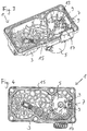
- the motor assembly 1 according to figures 1 and 2 comprises a housing 3, which is typically made of metal and produced in a casting process.
- the housing 3 receives an electric motor 5 which has a shaft 11 protruding on a first side 15 of the motor assembly 1. Furthermore, two terminals 13 of the electric motor 5 for electric connection of the motor 5 to a motor control unit 7 protrude from the first side 15 of the motor assembly 1.
- the housing 3 also receives a motor control unit 7 which comprises a number of motor control devices arranged on a leadframe and overmolded with a plastic housing. Since the motor control unit 7 is arranged on a second side of the motor assembly 1, which is not shown in figure 1 , only the pins 9 of the motor control unit 7 are shown in the figures. The two pins 9 protrude on the first side 15 of the motor assembly 1 and are provided to electrically connect the electric motor 5 to the motor control unit 7. Therefore, the pins 9 have to be brought into electrical contact with the terminals 13 during assembly. To make contact between the pins 9 and the terminals 13, the distance between them has to be bridged.
- a motor control unit 7 which comprises a number of motor control devices arranged on a leadframe and overmolded with a plastic housing. Since the motor control unit 7 is arranged on a second side of the motor assembly 1, which is not shown in figure 1 , only the pins 9 of the motor control unit 7 are shown in the figures. The two pins 9 protrude on the first side 15 of the
- Figure 3 shows a perspective view of the motor assembly 1 according to figure 1 during an assembly step, in which the pins 9 are connected to the terminals 13.
- a plan view of the motor assembly 1 during this assembly step is shown in figure 4 .
- Figure 5 shows a side view of a detail of the motor assembly 1 after the second portion 17 of the pins 9 has been bent to make contact with the terminals 13.
- the second portions 17 of the pins 9 make contact with the terminals 13 and can thus be connected by a welding point 19.
- only two welding points 19 are required to connect the electric motor 5 with the motor control unit 7.
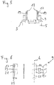
- Figure 6 shows different views of a pin 9 of the motor control unit 7 during a processing step.
- the pin is part of the leadframe of the motor control unit 7 and has a first portion 21, a second portion 17 and a weak portion 23 which is arranged between the first portion 21 and the second portion 17. Furthermore, the pin 9 has a lower part 25 which is connected to or part of the leadframe (not shown).
- the weak portion 23 has a lower yield strength than the first portion 21 and the second portion 17 and therefore yields more easily to a bending force which is applied during assembly. In particular, it has a lower yield strength with respect to a bending force which is applied in a certain bending direction. In the embodiment shown in figure 6 , the lower yield strength is achieved by a lower material thickness of the pin 9 in the weak portion 23 which is achieved by a cut-out of material.
- Figure 7 shows several views of the pin 9 according to figure 6 during a later processing step.
- the pin 9 has been folded around its longitudinal axis L to form an inner part 27 and an outer part 29.
- the outer part 29 provides a surface area to facilitate welding of the pin 9 to the terminal 13.
- the weak portion 23, due to the cut-out, has no outer part 29.
- the inner part 27 and the outer part 29 are perpendicular to each other.
- the pin 9 has also been folded around the horizontal axis, i.e. in the plane of the first side 15 of the motor assembly 1, so that the lower part 25 is parallel to the plane of the first side 15.
- Figure 7 shows the pin 9 in an original orientation after the molding process, in which the plastic housing of the motor control unit 7 is formed, while figure 8 shows the pin 9 after the assembly of the motor control unit with the housing 3 and the electric motor 5 and after the second portion 17 has been bent by an angle ⁇ of 90 degrees into an assembly orientation to make contact with the terminals 13.
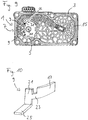
- Figure 9 shows a motor assembly 1 according to a second embodiment. This embodiment differs from the first embodiment in the shape of the pins 9 and in the direction of a bending force required to bend the second portion 17 of the pins 9 into an assembly position.
- the second portions 17 of the pins 9 are bent horizontally, that is around an axis M perpendicular to the plane of the first side 15, according to the arrow 31 by an angle ⁇ of less than 90 degrees.
- Figure 10 shows a perspective view of a possible shape of the pins 9 according to the second embodiment in its original orientation.
Landscapes
- Engineering & Computer Science (AREA)
- Chemical & Material Sciences (AREA)
- Combustion & Propulsion (AREA)
- Mechanical Engineering (AREA)
- General Engineering & Computer Science (AREA)
- Power Engineering (AREA)
- Manufacturing & Machinery (AREA)
- Motor Or Generator Frames (AREA)
Abstract
Description
- The present invention relates to a motor control unit for an electric motor for actuating a valve of the vehicle. Furthermore, it relates to a motor assembly comprising the motor control unit and to a process for assembling the motor assembly.
- In turbocharged vehicles, a wastegate is used to divert exhaust gases away from the turbine wheel to prevent a built-up of exhaust pressure. One possible way to actuate a wastegate of the vehicle is by using an electric motor which opens and closes the wastegate according to demand. The electric motor is controlled by a motor control unit which is often integrated with the electric motor in a common housing. Typically, the motor control unit comprises a number of motor control devices, for example a microcontroller or a microprocessor, which are arranged on a leadframe and at least partially overmolded with a plastic housing to protect the electronic components from the environment.
- To electrically connect the motor control unit to the electric motor, pins of the leadframe have to be connected to terminals of the electric motor. This is done by inserting connectors of a metal material which bridge the distance between the pins of the leadframe and the terminals of the electric motor and which are welded to the pins as well as to the terminals.
- Other possibilities to connect a motor control unit to an electric motor are known from
EP 153832182 - It is an object of the present invention to facilitate the connection of the pins of the leadframe with the electric motor and thereby to simplify the assembly of the motor assembly. This object is achieved by means of the motor control unit according to claim 1, the motor assembly according to
claim 5 and the process for assembling the motor assembly according to claim 8. - Advantageous embodiments and developments are objects of the dependent claims.
- According to a first aspect of the invention, a motor control unit for an electric motor for actuating a valve of a vehicle is provided, the motor control unit comprising a leadframe at least partially overmolded with a plastic housing, the leadframe supporting a number of motor control devices arranged in the housing, the leadframe having at least two pins providing terminals for electrical connection to an electric motor. The pins protrude from the plastic housing. The pins have a first portion being in contact with the plastic housing and a second portion for making contact with terminals of the electric motor.
- Furthermore, the pins have a weak portion arranged between the first portion and the second portion, wherein the weak portion is adapted to being bent out of an original orientation into an assembly orientation in which the second portion of the pins make contact with terminals of the electric motor during assembly with the electric motor.
- The motor control unit has the advantage that the pins can be in an original, unbent orientation during molding, which facilitates the molding process. When the motor control unit is assembled with the electric motor, the pins can be bent out of the original orientation into an assembly orientation, in which they make contact with the terminals of the electric motor. Thus, no separate connector is needed. Furthermore, the number of welding points is reduced.
- The motor control unit can be used for any electrically actuated valve of a vehicle where the electric motor and its motor control unit are integrated in a common housing, for example a throttle valve or a wastegate.
- The weak portion, which is a portion yielding more easily to a bending force than surrounding portions of the pin, may be provided by a portion with a reduced material thickness. According to this embodiment, there is a portion between the first portion and the second portion, where the pin has a reduced thickness and can be bent easily and in a controlled way. The reduced material thickness may be produced during stamping of the leadframe or by a cut-out at a later step.
- Additionally or alternatively, the weak portion may be provided by a portion having no reinforcement structure, while the first portion and the second portion comprise a reinforcement structure. Such a reinforcement structure may be provided by a portion of material being arranged perpendicular to the pin.
- According to this embodiment, the first portion and the second portion comprise reinforcement structures, while the weak portion has no reinforcement and therefore can be bent more easily.
- The reinforcement structure may also be produced during stamping of the leadframe.
- According to a second aspect of the invention, a motor assembly is provided comprising an electric motor for actuating a valve of a vehicle and a motor control unit as described above. The weak portion has been bent out of an original orientation into an assembly orientation in which the pins make contact with terminals of the electric motor.
- The bent portion may be identified by a zone of material deformation of the pin.
- The motor assembly has the advantages described above in connection with the motor control unit.
- According to an embodiment, the first portion and the second portion are perpendicular to each other.
- According to this embodiment, the pin is bent vertically, that is around an axis parallel to a main plane of the assembly, by an angle of about 90° during assembly. This has the advantage, that the bending by 90 degrees can be implemented very easily in the production line with applying a bending force from above. Furthermore, a pin that has to be bent vertically into an assembly orientation can have smaller horizontal dimensions and it can be inserted more easily into an opening of the housing during assembly.
- The second portion can be connected to the motor terminal by welding. According to the present invention, only one welding point per pin is needed, which makes the assembly more economical.
- According to a third aspect of the invention, a process for assembling the described motor assembly is provided. The process comprises providing the described motor control unit and providing an electric motor for actuating a valve of a vehicle. Furthermore, a housing for receiving the motor control unit and the electric motor is provided and the motor control unit and the electric motor are assembled with the housing. After this, a force is applied on the pins to bend them from the original orientation into the assembly orientation and the second portions of the pins are connected to terminals of the electric motor.
- The second portions of the pins may be connected to the terminals of the electric motor by welding. Alternatively, they could be connected by clamping or some other means of electrical connection.
- According to an embodiment, the pins are bent from the original orientation into the assembly orientation vertically by an angle α of 90° as described above. Alternatively, the pins can be bent from the original orientation into the assembly orientation horizontally by an angle α with α ≤ 90°.
- Further advantages, advantageous embodiments and developments of the motor control unit, the motor assembly and the process for assembling a motor assembly will become apparent from the exemplary embodiments which are described below in association with the schematic figures.
- Figure 1
- shows a perspective view of a motor assembly according to a first embodiment of the invention,
- Figure 2
- shows a plan view of a first side of the motor assembly according to
figure 1 , - Figure 3
- shows a perspective view of the motor assembly according to
figure 1 during a further assembly step, - Figure 4
- shows a plan view of the motor assembly according to
figure 3 , - Figure 5
- shows a side view of a detail of the motor assembly according to
figures 3 and 4 , - Figure 6
- shows several views of a pin of the motor assembly according to
figure 1 , - Figure 7
- shows several views of the pin according to
figure 6 during a later processing step, - Figure 8
- shows several views of the pin according to
figures 6 and7 in a further processing step, - Figure 9
- shows a plan view of the motor assembly according to a second embodiment of the invention and
- Figure 10
- shows a perspective view of a
pin 9 according to the second embodiment. - The motor assembly 1 according to
figures 1 and 2 comprises ahousing 3, which is typically made of metal and produced in a casting process. Thehousing 3 receives anelectric motor 5 which has ashaft 11 protruding on afirst side 15 of the motor assembly 1. Furthermore, twoterminals 13 of theelectric motor 5 for electric connection of themotor 5 to amotor control unit 7 protrude from thefirst side 15 of the motor assembly 1. - The
housing 3 also receives amotor control unit 7 which comprises a number of motor control devices arranged on a leadframe and overmolded with a plastic housing. Since themotor control unit 7 is arranged on a second side of the motor assembly 1, which is not shown infigure 1 , only thepins 9 of themotor control unit 7 are shown in the figures. The twopins 9 protrude on thefirst side 15 of the motor assembly 1 and are provided to electrically connect theelectric motor 5 to themotor control unit 7. Therefore, thepins 9 have to be brought into electrical contact with theterminals 13 during assembly. To make contact between thepins 9 and theterminals 13, the distance between them has to be bridged. -
Figure 3 shows a perspective view of the motor assembly 1 according tofigure 1 during an assembly step, in which thepins 9 are connected to theterminals 13. A plan view of the motor assembly 1 during this assembly step is shown infigure 4 . - As can be seen in
figure 3 and 4 , asecond portion 17 of thepins 9 has been bent and brought into contact with theterminals 13. By bending thesecond portion 17 downwards, the distance between thepins 9 and theterminals 13 has been bridged. When thepins 9 have thus been brought into contact with theterminals 13, they are connected by welding. - This is shown in more detail in
figure 5 . The shape of thepins 9 is shown in more detail infigures 6 to 8 . -
Figure 5 shows a side view of a detail of the motor assembly 1 after thesecond portion 17 of thepins 9 has been bent to make contact with theterminals 13. As can be seen infigure 5 , thesecond portions 17 of thepins 9 make contact with theterminals 13 and can thus be connected by awelding point 19. According to this embodiment, only twowelding points 19 are required to connect theelectric motor 5 with themotor control unit 7. -
Figure 6 shows different views of apin 9 of themotor control unit 7 during a processing step. The pin is part of the leadframe of themotor control unit 7 and has afirst portion 21, asecond portion 17 and aweak portion 23 which is arranged between thefirst portion 21 and thesecond portion 17. Furthermore, thepin 9 has alower part 25 which is connected to or part of the leadframe (not shown). - The
weak portion 23 has a lower yield strength than thefirst portion 21 and thesecond portion 17 and therefore yields more easily to a bending force which is applied during assembly. In particular, it has a lower yield strength with respect to a bending force which is applied in a certain bending direction. In the embodiment shown infigure 6 , the lower yield strength is achieved by a lower material thickness of thepin 9 in theweak portion 23 which is achieved by a cut-out of material. -
Figure 7 shows several views of thepin 9 according tofigure 6 during a later processing step. In the state shown infigures 7 and 8 , thepin 9 has been folded around its longitudinal axis L to form aninner part 27 and anouter part 29. Theouter part 29 provides a surface area to facilitate welding of thepin 9 to the terminal 13. Theweak portion 23, due to the cut-out, has noouter part 29. - The
inner part 27 and theouter part 29 are perpendicular to each other. - The
pin 9 has also been folded around the horizontal axis, i.e. in the plane of thefirst side 15 of the motor assembly 1, so that thelower part 25 is parallel to the plane of thefirst side 15. -
Figure 7 shows thepin 9 in an original orientation after the molding process, in which the plastic housing of themotor control unit 7 is formed, whilefigure 8 shows thepin 9 after the assembly of the motor control unit with thehousing 3 and theelectric motor 5 and after thesecond portion 17 has been bent by an angle α of 90 degrees into an assembly orientation to make contact with theterminals 13. -
Figure 9 shows a motor assembly 1 according to a second embodiment. This embodiment differs from the first embodiment in the shape of thepins 9 and in the direction of a bending force required to bend thesecond portion 17 of thepins 9 into an assembly position. - According to the second embodiment, the
second portions 17 of thepins 9 are bent horizontally, that is around an axis M perpendicular to the plane of thefirst side 15, according to thearrow 31 by an angle α of less than 90 degrees. -
Figure 10 shows a perspective view of a possible shape of thepins 9 according to the second embodiment in its original orientation.
Claims (11)
- Motor control unit (7) for an electric motor (5) for actuating a valve of a vehicle,
the motor control unit (7) comprising a leadframe at least partially overmolded with a plastic housing, the leadframe supporting a number of motor control devices arranged in the housing, the leadframe having at least two pins (9) providing terminals for electrical connection to an electric motor (5),
wherein the pins (9) protrude from the plastic housing and have- a first portion (21) being in contact with the plastic housing;- a second portion (17) for making contact with terminals (13) of the electric motor (5) and- a weak portion (23) arranged between the first portion (21) and the second portion (17), wherein the weak portion (23) is adapted to being bent out of an original orientation into an assembly orientation in which the second portion (17) of the pin (9) makes contact with a terminal (13) of the electric motor (5) during assembly with the electric motor (5) . - Motor control unit (7) according to claim 1,
wherein the weak portion (23) is provided by a portion with a reduced material thickness. - Motor control unit (7) according to claim 1 or 2,
wherein the weak portion (23) is provided by a portion having no reinforcement structure, while the first portion (21) and the second portion (17) comprise a reinforcement structure. - Motor control unit (7) according to claim 3,
wherein the reinforcement structure is provided by a portion of material being arranged perpendicular to the pin (9). - Motor assembly (1) comprising- an electric motor (5) for actuating a valve of a vehicle,- a motor control unit (7) according to any one of claims 1 to 4 to control the electric motor (5),wherein the weak portion (23) has been bent out of an original orientation into an assembly orientation in which at least a second portion (17) of the pin (9) makes contact with a terminal (13) of the electric motor.
- Motor assembly (1) according to claim 5,
wherein the first portion (21) and the second portion (17) are perpendicular to each other. - Motor assembly (1) according to claim 5 or 6,
wherein the second portion (17) is connected to the motor terminal (13) by welding. - Process for assembling the motor assembly (1) according to claim 5, the process comprising- providing a motor control unit (7) according to any one of claims 1 to 4,- providing an electric motor (5) for actuating a valve of a vehicle,- providing a housing (3) for receiving the motor control unit (7) and the electric motor (5),- assembling the motor control unit (7) and the electric motor (5) with the housing (3),- applying a force on the pins (9) to bend them from the original orientation into the assembly orientation,- connecting the second portions (17) of the pins (9) to terminals (13) of the electric motor (5).
- Process according to claim 8,
wherein the second portions (17) of the pins (9) are connected to terminals (13) of the electric motor (5) by welding. - Process according to claim 8 or 9,
wherein the pins (9) are bent from the original orientation into the assembly orientation vertically by an angle α of 90 degrees. - Process according to claim 8 or 9,
wherein the pins (9) are bent from the original orientation into the assembly orientation horizontally by an angle α with α ≤ 90 degrees.
Priority Applications (1)
| Application Number | Priority Date | Filing Date | Title |
|---|---|---|---|
| EP18465583.5A EP3633829B1 (en) | 2018-10-01 | 2018-10-01 | Motor control unit for an electric motor, motor assembly and process for assembling a motor assembly |
Applications Claiming Priority (1)
| Application Number | Priority Date | Filing Date | Title |
|---|---|---|---|
| EP18465583.5A EP3633829B1 (en) | 2018-10-01 | 2018-10-01 | Motor control unit for an electric motor, motor assembly and process for assembling a motor assembly |
Publications (2)
| Publication Number | Publication Date |
|---|---|
| EP3633829A1 true EP3633829A1 (en) | 2020-04-08 |
| EP3633829B1 EP3633829B1 (en) | 2023-12-20 |
Family
ID=63965596
Family Applications (1)
| Application Number | Title | Priority Date | Filing Date |
|---|---|---|---|
| EP18465583.5A Active EP3633829B1 (en) | 2018-10-01 | 2018-10-01 | Motor control unit for an electric motor, motor assembly and process for assembling a motor assembly |
Country Status (1)
| Country | Link |
|---|---|
| EP (1) | EP3633829B1 (en) |
Citations (8)
| Publication number | Priority date | Publication date | Assignee | Title |
|---|---|---|---|---|
| DE7328355U (en) * | 1973-08-03 | 1974-01-10 | Neosid Pemetzrieder Kg | Electrical connector |
| JPH1040984A (en) * | 1996-07-23 | 1998-02-13 | Matsushita Electric Works Ltd | Terminal device and manufacturing method thereof |
| JP2005052850A (en) * | 2003-08-07 | 2005-03-03 | Toyo Kitchen & Living Co Ltd | Bending method for metallic plate and bent structure |
| EP1538321A2 (en) | 2003-11-20 | 2005-06-08 | Hitachi Ltd. | Electronically controlled throttle device |
| JP2007278123A (en) * | 2006-04-04 | 2007-10-25 | Aisan Ind Co Ltd | Throttle valve control device |
| US20080224553A1 (en) * | 2007-03-16 | 2008-09-18 | Keihin Corporation | Electric motor, rotary actuator and rotary apparatus |
| DE102009057491A1 (en) * | 2009-12-10 | 2011-06-16 | Apel, Helga | Throttle device is provided with throttle body with ring element and outer cylinder, where throttle body is provided with cross-pervading throttle shaft with attached butterfly valve |
| US20170256875A1 (en) * | 2016-03-04 | 2017-09-07 | International Business Machines Corporation | Electrical contact assembly for printed circuit boards |
Family Cites Families (3)
| Publication number | Priority date | Publication date | Assignee | Title |
|---|---|---|---|---|
| JP4367473B2 (en) * | 1999-11-01 | 2009-11-18 | 株式会社デンソー | Rotation angle detector |
| JP2011096695A (en) * | 2009-10-27 | 2011-05-12 | Mitsubishi Electric Corp | Semiconductor device |
| DE102010001545A1 (en) * | 2010-02-03 | 2011-08-04 | Robert Bosch GmbH, 70469 | Molded power module for electronic module of electric motor, has structural element enclosed by mold body, and interconnect device with insulation displacement connectors laterally protruding away from mold body to form electric contacts |
-
2018
- 2018-10-01 EP EP18465583.5A patent/EP3633829B1/en active Active
Patent Citations (8)
| Publication number | Priority date | Publication date | Assignee | Title |
|---|---|---|---|---|
| DE7328355U (en) * | 1973-08-03 | 1974-01-10 | Neosid Pemetzrieder Kg | Electrical connector |
| JPH1040984A (en) * | 1996-07-23 | 1998-02-13 | Matsushita Electric Works Ltd | Terminal device and manufacturing method thereof |
| JP2005052850A (en) * | 2003-08-07 | 2005-03-03 | Toyo Kitchen & Living Co Ltd | Bending method for metallic plate and bent structure |
| EP1538321A2 (en) | 2003-11-20 | 2005-06-08 | Hitachi Ltd. | Electronically controlled throttle device |
| JP2007278123A (en) * | 2006-04-04 | 2007-10-25 | Aisan Ind Co Ltd | Throttle valve control device |
| US20080224553A1 (en) * | 2007-03-16 | 2008-09-18 | Keihin Corporation | Electric motor, rotary actuator and rotary apparatus |
| DE102009057491A1 (en) * | 2009-12-10 | 2011-06-16 | Apel, Helga | Throttle device is provided with throttle body with ring element and outer cylinder, where throttle body is provided with cross-pervading throttle shaft with attached butterfly valve |
| US20170256875A1 (en) * | 2016-03-04 | 2017-09-07 | International Business Machines Corporation | Electrical contact assembly for printed circuit boards |
Also Published As
| Publication number | Publication date |
|---|---|
| EP3633829B1 (en) | 2023-12-20 |
Similar Documents
| Publication | Publication Date | Title |
|---|---|---|
| US20080207009A1 (en) | Female terminal for connector, connector, and electrical connection device | |
| US6737863B2 (en) | Rotation detecting device and method of producing same | |
| EP1990873B1 (en) | Case provided with connector and method for manufacturing such case | |
| JP2016212983A (en) | Connector and method of manufacturing the same | |
| US5685728A (en) | Rotary connector device | |
| JP2000500276A (en) | Squib connector socket assembly with shorting clips for automotive airbags | |
| EP3633829B1 (en) | Motor control unit for an electric motor, motor assembly and process for assembling a motor assembly | |
| US20110120768A1 (en) | Control unit | |
| US9849848B2 (en) | Motor vehicle component support and method for the production thereof | |
| EP2105997A2 (en) | Terminal cap | |
| US9831611B2 (en) | Electrical plug connector | |
| CN109417853A (en) | For manufacturing the method for being used for the electrical components carrier of automobile application | |
| EP0877451A2 (en) | Insert moulded product and method of manufacturing thereof | |
| US10900817B2 (en) | Sensor system and method for producing a sensor system | |
| EP1221744B1 (en) | Electrical connector | |
| US7045712B2 (en) | Method of producing an electronic device and electronic device | |
| CN102498319B (en) | Contact connection module for transmission control part, transmission control module and their manufacturing method | |
| JP2020170625A (en) | Resin molded product | |
| US7147520B2 (en) | Connection part and method for producing a connection part | |
| JP3901868B2 (en) | Electronic component mounting substrate and manufacturing method thereof | |
| JP2000082339A (en) | Bending structure of electric wire module | |
| JP4010203B2 (en) | Control module for automobile and manufacturing method thereof | |
| JP3494986B2 (en) | Wiring structure of automotive control unit | |
| US20040065222A1 (en) | Ignition device for a safety system | |
| EP1356997B1 (en) | Vehicle component having an electrical conductor adhesively secured into the component |
Legal Events
| Date | Code | Title | Description |
|---|---|---|---|
| PUAI | Public reference made under article 153(3) epc to a published international application that has entered the european phase |
Free format text: ORIGINAL CODE: 0009012 |
|
| STAA | Information on the status of an ep patent application or granted ep patent |
Free format text: STATUS: THE APPLICATION HAS BEEN PUBLISHED |
|
| AK | Designated contracting states |
Kind code of ref document: A1 Designated state(s): AL AT BE BG CH CY CZ DE DK EE ES FI FR GB GR HR HU IE IS IT LI LT LU LV MC MK MT NL NO PL PT RO RS SE SI SK SM TR |
|
| AX | Request for extension of the european patent |
Extension state: BA ME |
|
| RAP1 | Party data changed (applicant data changed or rights of an application transferred) |
Owner name: VITESCO TECHNOLOGIES GMBH |
|
| STAA | Information on the status of an ep patent application or granted ep patent |
Free format text: STATUS: REQUEST FOR EXAMINATION WAS MADE |
|
| 17P | Request for examination filed |
Effective date: 20201008 |
|
| RBV | Designated contracting states (corrected) |
Designated state(s): AL AT BE BG CH CY CZ DE DK EE ES FI FR GB GR HR HU IE IS IT LI LT LU LV MC MK MT NL NO PL PT RO RS SE SI SK SM TR |
|
| STAA | Information on the status of an ep patent application or granted ep patent |
Free format text: STATUS: EXAMINATION IS IN PROGRESS |
|
| 17Q | First examination report despatched |
Effective date: 20210830 |
|
| RAP3 | Party data changed (applicant data changed or rights of an application transferred) |
Owner name: VITESCO TECHNOLOGIES GMBH |
|
| P01 | Opt-out of the competence of the unified patent court (upc) registered |
Effective date: 20230530 |
|
| RIC1 | Information provided on ipc code assigned before grant |
Ipc: H01R 13/05 20060101ALN20230604BHEP Ipc: F02B 37/18 20060101ALN20230604BHEP Ipc: F02D 11/10 20060101ALN20230604BHEP Ipc: H01R 43/00 20060101ALI20230604BHEP Ipc: F02D 9/10 20060101ALI20230604BHEP Ipc: H02K 11/30 20160101ALI20230604BHEP Ipc: H02K 5/22 20060101AFI20230604BHEP |
|
| GRAP | Despatch of communication of intention to grant a patent |
Free format text: ORIGINAL CODE: EPIDOSNIGR1 |
|
| STAA | Information on the status of an ep patent application or granted ep patent |
Free format text: STATUS: GRANT OF PATENT IS INTENDED |
|
| RIC1 | Information provided on ipc code assigned before grant |
Ipc: H01R 13/05 20060101ALN20230626BHEP Ipc: F02B 37/18 20060101ALN20230626BHEP Ipc: F02D 11/10 20060101ALN20230626BHEP Ipc: H01R 43/00 20060101ALI20230626BHEP Ipc: F02D 9/10 20060101ALI20230626BHEP Ipc: H02K 11/30 20160101ALI20230626BHEP Ipc: H02K 5/22 20060101AFI20230626BHEP |
|
| INTG | Intention to grant announced |
Effective date: 20230718 |
|
| GRAS | Grant fee paid |
Free format text: ORIGINAL CODE: EPIDOSNIGR3 |
|
| GRAA | (expected) grant |
Free format text: ORIGINAL CODE: 0009210 |
|
| STAA | Information on the status of an ep patent application or granted ep patent |
Free format text: STATUS: THE PATENT HAS BEEN GRANTED |
|
| AK | Designated contracting states |
Kind code of ref document: B1 Designated state(s): AL AT BE BG CH CY CZ DE DK EE ES FI FR GB GR HR HU IE IS IT LI LT LU LV MC MK MT NL NO PL PT RO RS SE SI SK SM TR |
|
| REG | Reference to a national code |
Ref country code: GB Ref legal event code: FG4D |
|
| REG | Reference to a national code |
Ref country code: DE Ref legal event code: R096 Ref document number: 602018062850 Country of ref document: DE |
|
| REG | Reference to a national code |
Ref country code: CH Ref legal event code: EP |
|
| REG | Reference to a national code |
Ref country code: IE Ref legal event code: FG4D |
|
| PG25 | Lapsed in a contracting state [announced via postgrant information from national office to epo] |
Ref country code: GR Free format text: LAPSE BECAUSE OF FAILURE TO SUBMIT A TRANSLATION OF THE DESCRIPTION OR TO PAY THE FEE WITHIN THE PRESCRIBED TIME-LIMIT Effective date: 20240321 |
|
| REG | Reference to a national code |
Ref country code: LT Ref legal event code: MG9D |
|
| PG25 | Lapsed in a contracting state [announced via postgrant information from national office to epo] |
Ref country code: LT Free format text: LAPSE BECAUSE OF FAILURE TO SUBMIT A TRANSLATION OF THE DESCRIPTION OR TO PAY THE FEE WITHIN THE PRESCRIBED TIME-LIMIT Effective date: 20231220 |
|
| REG | Reference to a national code |
Ref country code: NL Ref legal event code: MP Effective date: 20231220 |
|
| PG25 | Lapsed in a contracting state [announced via postgrant information from national office to epo] |
Ref country code: ES Free format text: LAPSE BECAUSE OF FAILURE TO SUBMIT A TRANSLATION OF THE DESCRIPTION OR TO PAY THE FEE WITHIN THE PRESCRIBED TIME-LIMIT Effective date: 20231220 |
|
| PG25 | Lapsed in a contracting state [announced via postgrant information from national office to epo] |
Ref country code: LT Free format text: LAPSE BECAUSE OF FAILURE TO SUBMIT A TRANSLATION OF THE DESCRIPTION OR TO PAY THE FEE WITHIN THE PRESCRIBED TIME-LIMIT Effective date: 20231220 Ref country code: GR Free format text: LAPSE BECAUSE OF FAILURE TO SUBMIT A TRANSLATION OF THE DESCRIPTION OR TO PAY THE FEE WITHIN THE PRESCRIBED TIME-LIMIT Effective date: 20240321 Ref country code: FI Free format text: LAPSE BECAUSE OF FAILURE TO SUBMIT A TRANSLATION OF THE DESCRIPTION OR TO PAY THE FEE WITHIN THE PRESCRIBED TIME-LIMIT Effective date: 20231220 Ref country code: ES Free format text: LAPSE BECAUSE OF FAILURE TO SUBMIT A TRANSLATION OF THE DESCRIPTION OR TO PAY THE FEE WITHIN THE PRESCRIBED TIME-LIMIT Effective date: 20231220 Ref country code: BG Free format text: LAPSE BECAUSE OF FAILURE TO SUBMIT A TRANSLATION OF THE DESCRIPTION OR TO PAY THE FEE WITHIN THE PRESCRIBED TIME-LIMIT Effective date: 20240320 |
|
| REG | Reference to a national code |
Ref country code: AT Ref legal event code: MK05 Ref document number: 1643311 Country of ref document: AT Kind code of ref document: T Effective date: 20231220 |
|
| PG25 | Lapsed in a contracting state [announced via postgrant information from national office to epo] |
Ref country code: NL Free format text: LAPSE BECAUSE OF FAILURE TO SUBMIT A TRANSLATION OF THE DESCRIPTION OR TO PAY THE FEE WITHIN THE PRESCRIBED TIME-LIMIT Effective date: 20231220 |
|
| PG25 | Lapsed in a contracting state [announced via postgrant information from national office to epo] |
Ref country code: SE Free format text: LAPSE BECAUSE OF FAILURE TO SUBMIT A TRANSLATION OF THE DESCRIPTION OR TO PAY THE FEE WITHIN THE PRESCRIBED TIME-LIMIT Effective date: 20231220 Ref country code: RS Free format text: LAPSE BECAUSE OF FAILURE TO SUBMIT A TRANSLATION OF THE DESCRIPTION OR TO PAY THE FEE WITHIN THE PRESCRIBED TIME-LIMIT Effective date: 20231220 Ref country code: NO Free format text: LAPSE BECAUSE OF FAILURE TO SUBMIT A TRANSLATION OF THE DESCRIPTION OR TO PAY THE FEE WITHIN THE PRESCRIBED TIME-LIMIT Effective date: 20240320 Ref country code: NL Free format text: LAPSE BECAUSE OF FAILURE TO SUBMIT A TRANSLATION OF THE DESCRIPTION OR TO PAY THE FEE WITHIN THE PRESCRIBED TIME-LIMIT Effective date: 20231220 Ref country code: LV Free format text: LAPSE BECAUSE OF FAILURE TO SUBMIT A TRANSLATION OF THE DESCRIPTION OR TO PAY THE FEE WITHIN THE PRESCRIBED TIME-LIMIT Effective date: 20231220 Ref country code: HR Free format text: LAPSE BECAUSE OF FAILURE TO SUBMIT A TRANSLATION OF THE DESCRIPTION OR TO PAY THE FEE WITHIN THE PRESCRIBED TIME-LIMIT Effective date: 20231220 |
|
| PG25 | Lapsed in a contracting state [announced via postgrant information from national office to epo] |
Ref country code: IS Free format text: LAPSE BECAUSE OF FAILURE TO SUBMIT A TRANSLATION OF THE DESCRIPTION OR TO PAY THE FEE WITHIN THE PRESCRIBED TIME-LIMIT Effective date: 20240420 |
|
| PG25 | Lapsed in a contracting state [announced via postgrant information from national office to epo] |
Ref country code: AT Free format text: LAPSE BECAUSE OF FAILURE TO SUBMIT A TRANSLATION OF THE DESCRIPTION OR TO PAY THE FEE WITHIN THE PRESCRIBED TIME-LIMIT Effective date: 20231220 Ref country code: CZ Free format text: LAPSE BECAUSE OF FAILURE TO SUBMIT A TRANSLATION OF THE DESCRIPTION OR TO PAY THE FEE WITHIN THE PRESCRIBED TIME-LIMIT Effective date: 20231220 |
|
| PG25 | Lapsed in a contracting state [announced via postgrant information from national office to epo] |
Ref country code: SK Free format text: LAPSE BECAUSE OF FAILURE TO SUBMIT A TRANSLATION OF THE DESCRIPTION OR TO PAY THE FEE WITHIN THE PRESCRIBED TIME-LIMIT Effective date: 20231220 |
|
| PG25 | Lapsed in a contracting state [announced via postgrant information from national office to epo] |
Ref country code: SM Free format text: LAPSE BECAUSE OF FAILURE TO SUBMIT A TRANSLATION OF THE DESCRIPTION OR TO PAY THE FEE WITHIN THE PRESCRIBED TIME-LIMIT Effective date: 20231220 Ref country code: SK Free format text: LAPSE BECAUSE OF FAILURE TO SUBMIT A TRANSLATION OF THE DESCRIPTION OR TO PAY THE FEE WITHIN THE PRESCRIBED TIME-LIMIT Effective date: 20231220 Ref country code: RO Free format text: LAPSE BECAUSE OF FAILURE TO SUBMIT A TRANSLATION OF THE DESCRIPTION OR TO PAY THE FEE WITHIN THE PRESCRIBED TIME-LIMIT Effective date: 20231220 Ref country code: IT Free format text: LAPSE BECAUSE OF FAILURE TO SUBMIT A TRANSLATION OF THE DESCRIPTION OR TO PAY THE FEE WITHIN THE PRESCRIBED TIME-LIMIT Effective date: 20231220 Ref country code: IS Free format text: LAPSE BECAUSE OF FAILURE TO SUBMIT A TRANSLATION OF THE DESCRIPTION OR TO PAY THE FEE WITHIN THE PRESCRIBED TIME-LIMIT Effective date: 20240420 Ref country code: EE Free format text: LAPSE BECAUSE OF FAILURE TO SUBMIT A TRANSLATION OF THE DESCRIPTION OR TO PAY THE FEE WITHIN THE PRESCRIBED TIME-LIMIT Effective date: 20231220 Ref country code: CZ Free format text: LAPSE BECAUSE OF FAILURE TO SUBMIT A TRANSLATION OF THE DESCRIPTION OR TO PAY THE FEE WITHIN THE PRESCRIBED TIME-LIMIT Effective date: 20231220 Ref country code: AT Free format text: LAPSE BECAUSE OF FAILURE TO SUBMIT A TRANSLATION OF THE DESCRIPTION OR TO PAY THE FEE WITHIN THE PRESCRIBED TIME-LIMIT Effective date: 20231220 |
|
| PG25 | Lapsed in a contracting state [announced via postgrant information from national office to epo] |
Ref country code: PL Free format text: LAPSE BECAUSE OF FAILURE TO SUBMIT A TRANSLATION OF THE DESCRIPTION OR TO PAY THE FEE WITHIN THE PRESCRIBED TIME-LIMIT Effective date: 20231220 Ref country code: PT Free format text: LAPSE BECAUSE OF FAILURE TO SUBMIT A TRANSLATION OF THE DESCRIPTION OR TO PAY THE FEE WITHIN THE PRESCRIBED TIME-LIMIT Effective date: 20240422 |
|
| PG25 | Lapsed in a contracting state [announced via postgrant information from national office to epo] |
Ref country code: PT Free format text: LAPSE BECAUSE OF FAILURE TO SUBMIT A TRANSLATION OF THE DESCRIPTION OR TO PAY THE FEE WITHIN THE PRESCRIBED TIME-LIMIT Effective date: 20240422 Ref country code: PL Free format text: LAPSE BECAUSE OF FAILURE TO SUBMIT A TRANSLATION OF THE DESCRIPTION OR TO PAY THE FEE WITHIN THE PRESCRIBED TIME-LIMIT Effective date: 20231220 |
|
| REG | Reference to a national code |
Ref country code: DE Ref legal event code: R097 Ref document number: 602018062850 Country of ref document: DE |
|
| PG25 | Lapsed in a contracting state [announced via postgrant information from national office to epo] |
Ref country code: DK Free format text: LAPSE BECAUSE OF FAILURE TO SUBMIT A TRANSLATION OF THE DESCRIPTION OR TO PAY THE FEE WITHIN THE PRESCRIBED TIME-LIMIT Effective date: 20231220 |
|
| PLBE | No opposition filed within time limit |
Free format text: ORIGINAL CODE: 0009261 |
|
| STAA | Information on the status of an ep patent application or granted ep patent |
Free format text: STATUS: NO OPPOSITION FILED WITHIN TIME LIMIT |
|
| PG25 | Lapsed in a contracting state [announced via postgrant information from national office to epo] |
Ref country code: SI Free format text: LAPSE BECAUSE OF FAILURE TO SUBMIT A TRANSLATION OF THE DESCRIPTION OR TO PAY THE FEE WITHIN THE PRESCRIBED TIME-LIMIT Effective date: 20231220 |
|
| PG25 | Lapsed in a contracting state [announced via postgrant information from national office to epo] |
Ref country code: SI Free format text: LAPSE BECAUSE OF FAILURE TO SUBMIT A TRANSLATION OF THE DESCRIPTION OR TO PAY THE FEE WITHIN THE PRESCRIBED TIME-LIMIT Effective date: 20231220 Ref country code: DK Free format text: LAPSE BECAUSE OF FAILURE TO SUBMIT A TRANSLATION OF THE DESCRIPTION OR TO PAY THE FEE WITHIN THE PRESCRIBED TIME-LIMIT Effective date: 20231220 |
|
| 26N | No opposition filed |
Effective date: 20240923 |
|
| REG | Reference to a national code |
Ref country code: DE Ref legal event code: R081 Ref document number: 602018062850 Country of ref document: DE Owner name: SCHAEFFLER TECHNOLOGIES AG & CO. KG, DE Free format text: FORMER OWNER: VITESCO TECHNOLOGIES GMBH, 93055 REGENSBURG, DE |
|
| REG | Reference to a national code |
Ref country code: CH Ref legal event code: PL |
|
| GBPC | Gb: european patent ceased through non-payment of renewal fee |
Effective date: 20241001 |
|
| PG25 | Lapsed in a contracting state [announced via postgrant information from national office to epo] |
Ref country code: MC Free format text: LAPSE BECAUSE OF FAILURE TO SUBMIT A TRANSLATION OF THE DESCRIPTION OR TO PAY THE FEE WITHIN THE PRESCRIBED TIME-LIMIT Effective date: 20231220 |
|
| PG25 | Lapsed in a contracting state [announced via postgrant information from national office to epo] |
Ref country code: GB Free format text: LAPSE BECAUSE OF NON-PAYMENT OF DUE FEES Effective date: 20241001 |
|
| PG25 | Lapsed in a contracting state [announced via postgrant information from national office to epo] |
Ref country code: BE Free format text: LAPSE BECAUSE OF NON-PAYMENT OF DUE FEES Effective date: 20241031 Ref country code: LU Free format text: LAPSE BECAUSE OF NON-PAYMENT OF DUE FEES Effective date: 20241001 |
|
| PG25 | Lapsed in a contracting state [announced via postgrant information from national office to epo] |
Ref country code: FR Free format text: LAPSE BECAUSE OF NON-PAYMENT OF DUE FEES Effective date: 20241031 |
|
| PG25 | Lapsed in a contracting state [announced via postgrant information from national office to epo] |
Ref country code: CH Free format text: LAPSE BECAUSE OF NON-PAYMENT OF DUE FEES Effective date: 20241031 |
|
| REG | Reference to a national code |
Ref country code: BE Ref legal event code: MM Effective date: 20241031 |
|
| PG25 | Lapsed in a contracting state [announced via postgrant information from national office to epo] |
Ref country code: IE Free format text: LAPSE BECAUSE OF NON-PAYMENT OF DUE FEES Effective date: 20241001 |
|
| PGFP | Annual fee paid to national office [announced via postgrant information from national office to epo] |
Ref country code: DE Payment date: 20251031 Year of fee payment: 8 |
|
| PG25 | Lapsed in a contracting state [announced via postgrant information from national office to epo] |
Ref country code: CY Free format text: LAPSE BECAUSE OF FAILURE TO SUBMIT A TRANSLATION OF THE DESCRIPTION OR TO PAY THE FEE WITHIN THE PRESCRIBED TIME-LIMIT; INVALID AB INITIO Effective date: 20181001 |
|
| PG25 | Lapsed in a contracting state [announced via postgrant information from national office to epo] |
Ref country code: HU Free format text: LAPSE BECAUSE OF FAILURE TO SUBMIT A TRANSLATION OF THE DESCRIPTION OR TO PAY THE FEE WITHIN THE PRESCRIBED TIME-LIMIT; INVALID AB INITIO Effective date: 20181001 |
|
| PG25 | Lapsed in a contracting state [announced via postgrant information from national office to epo] |
Ref country code: TR Free format text: LAPSE BECAUSE OF FAILURE TO SUBMIT A TRANSLATION OF THE DESCRIPTION OR TO PAY THE FEE WITHIN THE PRESCRIBED TIME-LIMIT Effective date: 20231220 |