EP3633790A1 - Shared aperture antenna array - Google Patents
Shared aperture antenna array Download PDFInfo
- Publication number
- EP3633790A1 EP3633790A1 EP19211570.7A EP19211570A EP3633790A1 EP 3633790 A1 EP3633790 A1 EP 3633790A1 EP 19211570 A EP19211570 A EP 19211570A EP 3633790 A1 EP3633790 A1 EP 3633790A1
- Authority
- EP
- European Patent Office
- Prior art keywords
- antenna
- antennas
- array
- patches
- shared
- Prior art date
- Legal status (The legal status is an assumption and is not a legal conclusion. Google has not performed a legal analysis and makes no representation as to the accuracy of the status listed.)
- Withdrawn
Links
- 239000000758 substrate Substances 0.000 claims description 9
- 238000005070 sampling Methods 0.000 description 17
- 238000003384 imaging method Methods 0.000 description 10
- 238000000034 method Methods 0.000 description 9
- 230000010287 polarization Effects 0.000 description 9
- 238000003491 array Methods 0.000 description 7
- 238000013461 design Methods 0.000 description 6
- 238000005516 engineering process Methods 0.000 description 3
- 238000005259 measurement Methods 0.000 description 3
- 230000008878 coupling Effects 0.000 description 2
- 238000010168 coupling process Methods 0.000 description 2
- 238000005859 coupling reaction Methods 0.000 description 2
- 238000011161 development Methods 0.000 description 2
- 238000012216 screening Methods 0.000 description 2
- 238000010276 construction Methods 0.000 description 1
- 238000013480 data collection Methods 0.000 description 1
- 230000001066 destructive effect Effects 0.000 description 1
- 238000001514 detection method Methods 0.000 description 1
- 230000009977 dual effect Effects 0.000 description 1
- 238000011156 evaluation Methods 0.000 description 1
- 239000006260 foam Substances 0.000 description 1
- 238000005286 illumination Methods 0.000 description 1
- 239000002184 metal Substances 0.000 description 1
- 238000012986 modification Methods 0.000 description 1
- 230000004048 modification Effects 0.000 description 1
- 230000000149 penetrating effect Effects 0.000 description 1
- 238000012545 processing Methods 0.000 description 1
- 238000011160 research Methods 0.000 description 1
- 238000012163 sequencing technique Methods 0.000 description 1
- 238000004088 simulation Methods 0.000 description 1
- 238000001228 spectrum Methods 0.000 description 1
- 238000012546 transfer Methods 0.000 description 1
Images


Classifications
-
- H—ELECTRICITY
- H01—ELECTRIC ELEMENTS
- H01Q—ANTENNAS, i.e. RADIO AERIALS
- H01Q9/00—Electrically-short antennas having dimensions not more than twice the operating wavelength and consisting of conductive active radiating elements
- H01Q9/04—Resonant antennas
- H01Q9/0407—Substantially flat resonant element parallel to ground plane, e.g. patch antenna
- H01Q9/0428—Substantially flat resonant element parallel to ground plane, e.g. patch antenna radiating a circular polarised wave
- H01Q9/0435—Substantially flat resonant element parallel to ground plane, e.g. patch antenna radiating a circular polarised wave using two feed points
-
- G—PHYSICS
- G01—MEASURING; TESTING
- G01S—RADIO DIRECTION-FINDING; RADIO NAVIGATION; DETERMINING DISTANCE OR VELOCITY BY USE OF RADIO WAVES; LOCATING OR PRESENCE-DETECTING BY USE OF THE REFLECTION OR RERADIATION OF RADIO WAVES; ANALOGOUS ARRANGEMENTS USING OTHER WAVES
- G01S13/00—Systems using the reflection or reradiation of radio waves, e.g. radar systems; Analogous systems using reflection or reradiation of waves whose nature or wavelength is irrelevant or unspecified
- G01S13/02—Systems using reflection of radio waves, e.g. primary radar systems; Analogous systems
-
- G—PHYSICS
- G01—MEASURING; TESTING
- G01S—RADIO DIRECTION-FINDING; RADIO NAVIGATION; DETERMINING DISTANCE OR VELOCITY BY USE OF RADIO WAVES; LOCATING OR PRESENCE-DETECTING BY USE OF THE REFLECTION OR RERADIATION OF RADIO WAVES; ANALOGOUS ARRANGEMENTS USING OTHER WAVES
- G01S7/00—Details of systems according to groups G01S13/00, G01S15/00, G01S17/00
- G01S7/02—Details of systems according to groups G01S13/00, G01S15/00, G01S17/00 of systems according to group G01S13/00
- G01S7/03—Details of HF subsystems specially adapted therefor, e.g. common to transmitter and receiver
-
- H—ELECTRICITY
- H01—ELECTRIC ELEMENTS
- H01Q—ANTENNAS, i.e. RADIO AERIALS
- H01Q21/00—Antenna arrays or systems
- H01Q21/0006—Particular feeding systems
-
- H—ELECTRICITY
- H01—ELECTRIC ELEMENTS
- H01Q—ANTENNAS, i.e. RADIO AERIALS
- H01Q21/00—Antenna arrays or systems
- H01Q21/06—Arrays of individually energised antenna units similarly polarised and spaced apart
- H01Q21/061—Two dimensional planar arrays
- H01Q21/062—Two dimensional planar arrays using dipole aerials
-
- H—ELECTRICITY
- H01—ELECTRIC ELEMENTS
- H01Q—ANTENNAS, i.e. RADIO AERIALS
- H01Q21/00—Antenna arrays or systems
- H01Q21/24—Combinations of antenna units polarised in different directions for transmitting or receiving circularly and elliptically polarised waves or waves linearly polarised in any direction
-
- H—ELECTRICITY
- H01—ELECTRIC ELEMENTS
- H01Q—ANTENNAS, i.e. RADIO AERIALS
- H01Q9/00—Electrically-short antennas having dimensions not more than twice the operating wavelength and consisting of conductive active radiating elements
- H01Q9/04—Resonant antennas
- H01Q9/16—Resonant antennas with feed intermediate between the extremities of the antenna, e.g. centre-fed dipole
- H01Q9/28—Conical, cylindrical, cage, strip, gauze, or like elements having an extended radiating surface; Elements comprising two conical surfaces having collinear axes and adjacent apices and fed by two-conductor transmission lines
- H01Q9/285—Planar dipole
-
- G—PHYSICS
- G01—MEASURING; TESTING
- G01S—RADIO DIRECTION-FINDING; RADIO NAVIGATION; DETERMINING DISTANCE OR VELOCITY BY USE OF RADIO WAVES; LOCATING OR PRESENCE-DETECTING BY USE OF THE REFLECTION OR RERADIATION OF RADIO WAVES; ANALOGOUS ARRANGEMENTS USING OTHER WAVES
- G01S13/00—Systems using the reflection or reradiation of radio waves, e.g. radar systems; Analogous systems using reflection or reradiation of waves whose nature or wavelength is irrelevant or unspecified
- G01S13/02—Systems using reflection of radio waves, e.g. primary radar systems; Analogous systems
- G01S2013/0236—Special technical features
- G01S2013/0245—Radar with phased array antenna
- G01S2013/0254—Active array antenna
Definitions
- This invention relates to antenna arrays. More specifically, this invention relates to a shared aperture antenna array wherein elements or portions of neighboring antennas are shared to create additional antennas.
- linear and two-dimensional radar imaging antenna arrays use sequential sampling, synthetic apertures, and sparse array techniques to achieve sampling/pixel density. All of these techniques focus on switching networks to use antennas in the array as transmitters/receivers.
- linear holographic radar imaging arrays typically use two separate linear arrays of cavity-backed spiral antennas to transmit and receive circularly polarized signals.
- Microwave and millimeter-wave technologies or synthetic aperture imaging techniques have been developed for a wide variety of applications. These applications include radar (GPR), through-wall and inner wall imaging, body measurements, security screening, and non-destructive evaluation.
- the imaging techniques developed are fully three-dimensional and typically operate by scanning a wide bandwidth radar transceiver over a planar or cylindrical aperture, and using mathematical techniques to focus the data into a three-dimensional image. Examples of these techniques are described in U.S. Patent Nos. 5,557,283 and 5,859,609 by Sheen et al. It is advantageous to use mathematical focusing for these applications because it allows for the use of large apertures and extreme near-field operation, where it would be inconvenient or impossible to use physical focusing elements such as lenses or reflectors. Additionally, scanning the transmitter along with the receiver doubles the resolution relative to fixed transmitters and provides superior illumination quality by using a large diversity of transmitters.
- Sequentially-switched linear array technology that allows one dimension of a planar or cylindrical aperture to be effectively scanned electronically at high speed has been developed. This is accomplished by sequencing through each antenna element or transmit/receive antenna pair using microwave or millimeter-wave switching networks connected to the radar transceiver.
- Phased array antenna systems are well known in the antenna art. Such antennas are generally comprised of radiating elements that are individually controllable with regard to relative phase and amplitude. The antenna pattern of the array is selectively determined by the geometry of the individual elements and the selected phase/amplitude relationships among the elements. Typical radiating elements for such antenna systems may include dipoles, patches, waveguides, or slots.
- a planar antenna element is known in the art as the Foursquare antenna, as described in U.S. Patent No. 5,926,137 to Nealy . It comprises four square radiating elements on the top side of a dielectric substrate which is separated from a ground plane by a foam separator. At least two coaxial feeds connect to interior corners of opposing pairs of radiating elements.
- This Foursquare antenna provides wideband performance and several practical advantages for commercial and military applications.
- Various polarizations can be achieved with the Foursquare antenna - for example, dual linear, circular and elliptical polarizations of any orientation - and its features are a low-profile geometry and compact radiating element size.
- the continuing challenge with the development of antenna arrays used in holographic imaging applications is to reduce the size and weight and achieve adequate physical sampling/pixel spacing in the array.
- the required sampling is typically a minimum of one-half wavelength.
- the physical sampling of the array is determined by the spacing of transmit and receive antennas used in the array system. Since the physical size of the antenna is constrained by the bandwidth of operation, the physical size of the antennas cannot be greatly reduced to achieve any noticeable increase in sampling density.
- an antenna array is disclosed.
- the antennas array includes an array of antennas wherein elements of neighboring antennas are shared to create additional antennas.
- the shared elements include radiating patches and apertures. Apertures of neighboring antennas overlap.
- feed points of the antennas are phased so that opposing dipole patches are 180 degrees out of phase.
- each antenna is a foursquare antenna.
- the antennas are printed on a dielectric substrate and located above a ground plane.
- the antenna array includes a phase shifting network with single-pole-single-throw reflective switches coupled to the antennas.
- the array of antennas is a linear array of antennas or a two-dimensional array of antennas.
- a shared aperture antenna array in another embodiment, includes an array of antennas. Each antenna shares an aperture with neighboring antennas.
- a method of increasing sampling density using a shared aperture antenna array includes providing an array of antennas; and creating additional antennas by sharing elements of neighboring antennas within the array.
- the method includes electrically coupling a phase shifting network with single-pole-single-throw reflective switches to the antennas.
- a shared aperture antenna array in another embodiment, includes an array having a plurality of antennas wherein each antenna shares at least one radiating patch and an aperture with a neighboring antenna. At least one feed point is phased so that opposing dipole patches are 180 degrees out of phase.
- the antennas are printed on a dielectric substrate and located above a ground plane.
- the present invention describes an array of antennas that shares components or elements of neighboring antennas to create additional antennas.
- the shared aperture array creates additional antenna elements within an array of broadband planar dipole antennas, allowing for increased array sampling and pixel density than current antenna array designs.
- the shared aperture array can achieve pixel sampling distances much smaller than one-half wavelength with a single array of antennas.
- the sharing of elements of neighboring antennas to create additional antennas reduces the physical size of the arrays by a factor of two, allows for fully polarimetric data sets with a single array, increases the physical sampling - reducing pixel sampling in the array - to one-twelfth of a wavelength, and enables imaging systems with reduced weight.
- the present invention discloses an array of broadband planar dipoles and maintains desirable circular polarization properties of transmitted and received signals using an appropriate feed network.
- FIG. 1 is a schematic of a shared aperture antenna array 100, in accordance with one embodiment of the present invention.
- the antenna array 100 includes a first antenna 110, a second antenna 120, and a third antenna 130.
- each antenna 110, 120, and 130 is a foursquare antenna that includes four radiating patches or metal sheets 140.
- Each radiating patch 140 includes at least one feed point 150.
- the antenna array 100 is not limited to any particular number of antennas, radiating patches or feed points. Note also that the antenna array can be a single (linear) or a two-dimensional array of antennas.
- the shared elements include the radiating patches 140 and apertures.
- the radiating patches 140 of the first antenna 110 and the third antenna 130 are shared to create the second antenna 120.
- the same radiating patch is used for two antennas, and two radiating patches belong to two antennas. This is achieved without changing the physical size of the array 100.
- the number of antennas is increased as the radiating patches of neighboring antennas are shared. This results in having nearly twice as many antennas in the same space compared to current or prior antenna array designs.
- the first antenna 110 has an aperture consisting of its four radiating patches.
- the second and third antennas 120 and 130 each have apertures above them. However since the first antenna 110 and the second antenna 120 overlap, they have a shared aperture. Similarly, since the second and third antennas 120 and 130 overlap, they also share an aperture. Each antenna shares an aperture with neighboring antennas.
- FIG. 2 is a schematic of a phase shifting network 200 coupled to antennas using single-pole-single-throw reflective switches, in accordance with one embodiment of the present invention.
- the network 200 includes two separate 180 degree hybrids or baluns plus a separate 90 degree hybrid for each antenna.
- the feed points of each antenna are coupled to the 180 degree hybrid couplers via single-pole-single-throw reflective switches.
- a transfer switch is coupled between the difference signal outputs of the 180 degree hybrid couplers and the 90 degree hybrid coupler, which is used to produce circular polarization.
- a second switch is coupled between the 90 degree output port and a transceiver - the transmit switch and the receive switch - which is used for generating signals to be transmitted and processing received signals.
- the array transmits with right-hand circular polarization (RHCP) and receives with left-hand circular polarization (LHCP).
- RHCP right-hand circular polarization
- LHCP left-hand circular polarization
- the antenna array of the present invention was simulated and verified using a finite element model of a planar broadband foursquare patch/dipole array with a center frequency of approximately 10 GHz.
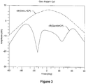
- Figure 3 is a graph showing the antenna gain using this array configuration, which is similar in design to the antenna array of Figure 1 .
- Results of the simulation demonstrated the following: an increased sampling/pixel density - e.g., one-twelfth wavelength sampling, which is 3-6X better than existing array designs - reduced array surface by 50%, the ability to utilize co-polarized and cross-polarized signals with a single array, and antenna gain by approximately 5 dB relative to cavity-backed spiral array designs.
- Antenna geometries and feed network components are frequency scalable, so this design may be used over the RF, microwave, and mm-wave spectrums.
- the performance of the linear antenna array can be extrapolated using an infinite array model of the shared aperture antenna used in a 2-D antenna array configuration.
- the shared aperture antenna array of the present invention was able to maintain the desired antenna gain, voltage standing wave ratio (VSWR), and circular polarized properties of the baseline antenna by employing a reflective switch at the input to the shared ports of the foursquare antenna patches to appear as a short-circuit when the element was not being used.
- VSWR voltage standing wave ratio
- the shared aperture antenna array demonstrated the ability to obtain both right-handed and left-handed senses of circular polarization using only a single array of antennas. Sampling configurations within the array allow for improved physical sampling within the antenna array as small as one-twelfth of a wavelength.
- the present invention is applicable to any frequency band via frequency scaling of the physical antenna dimensions.
- linear and 2-D holographic radar arrays include, but are not limited, to the following: security screening, handheld holographic imaging systems, ground penetrating radar (GPR), and clothing/apparel measurements.
- GPR ground penetrating radar
- the shared aperture array allows for increased physical sampling throughout the antenna array, which results in high-fidelity and multiple polarization state based images.
- High-fidelity images in conjunction with multiple polarization state data sets can increase the probability of detection of threat objects and improve the accuracy for apparel measurements.
- an antenna array comprising: an array of antennas, wherein elements of neighboring antennas are shared to create additional antennas.
- the shared elements include radiating patches and apertures.
- the feed points of the antennas are phased so that opposing dipole patches are 180 degrees out of phase.
- the apertures of the neighboring antennas overlap.
- each antenna is a foursquare antenna.
- the antennas are printed on a dielectric substrate and located above a ground plane.
- the antenna array further comprises a phase shifting network with single-pole-single-throw reflective switches coupled to the antennas.
- the array of antennas is a linear array of antennas or a two-dimensional array of antennas.
- the present invention provides a shared aperture antenna array comprising: an array of antennas, wherein each antenna shares an aperture with neighboring antennas.
- the antennas are printed on a dielectric substrate and located above a ground plane.
- the apertures of neighboring antennas overlap.
- At least one radiating patch of each antenna is shared with the neighboring antennas.
- at least one feed point of each antenna is phased so that opposing dipole patches are 180 degrees out of phase.
- each antenna in the array is a foursquare antenna.
- the shared aperture antenna array further comprises a phase shifting network with single-pole-single-throw reflective switches coupled to the antennas.
- the array of antennas is a linear array of antennas or a two-dimensional array of antennas.
- the present invention provides a method of increasing sampling density using a shared aperture antenna array comprising:
- the antennas are printed on a dielectric substrate and located above a ground plane.
- the shared elements include apertures and radiating patches.
- the feed points of the antennas are phased so that opposing dipole patches are 180 degrees out of phase.
- the apertures of the neighboring antennas overlap.
- each antenna is a foursquare antenna.
- the method further comprises electrically coupling a phase shifting network with single-pole-single-throw reflective switches to the antennas.
- the present invention provides a shared aperture antenna array comprising: an array having a plurality of antennas, wherein each antenna shares at least one radiating patch and an aperture with a neighboring antenna, and wherein at least one feed point is phased so that opposing dipole patches are 180 degrees out of phase, and wherein the antennas are printed on a dielectric substrate and located above a ground plane.
Landscapes
- Engineering & Computer Science (AREA)
- Radar, Positioning & Navigation (AREA)
- Remote Sensing (AREA)
- Computer Networks & Wireless Communication (AREA)
- Physics & Mathematics (AREA)
- General Physics & Mathematics (AREA)
- Variable-Direction Aerials And Aerial Arrays (AREA)
- Aerials With Secondary Devices (AREA)
Abstract
Description
- This application claims priority to
U.S. Patent Application No. 14/178,998, filed February 12, 2014 - This invention was made with Government support under Contract DE-AC05-76RLO1830 awarded by the U.S. Department of Energy. The Government has certain rights in the invention.
- This invention relates to antenna arrays. More specifically, this invention relates to a shared aperture antenna array wherein elements or portions of neighboring antennas are shared to create additional antennas.
- Current technologies for linear and two-dimensional radar imaging antenna arrays use sequential sampling, synthetic apertures, and sparse array techniques to achieve sampling/pixel density. All of these techniques focus on switching networks to use antennas in the array as transmitters/receivers. For example, linear holographic radar imaging arrays typically use two separate linear arrays of cavity-backed spiral antennas to transmit and receive circularly polarized signals.
- Microwave and millimeter-wave technologies or synthetic aperture imaging techniques have been developed for a wide variety of applications. These applications include radar (GPR), through-wall and inner wall imaging, body measurements, security screening, and non-destructive evaluation. The imaging techniques developed are fully three-dimensional and typically operate by scanning a wide bandwidth radar transceiver over a planar or cylindrical aperture, and using mathematical techniques to focus the data into a three-dimensional image. Examples of these techniques are described in
U.S. Patent Nos. 5,557,283 and5,859,609 by Sheen et al. It is advantageous to use mathematical focusing for these applications because it allows for the use of large apertures and extreme near-field operation, where it would be inconvenient or impossible to use physical focusing elements such as lenses or reflectors. Additionally, scanning the transmitter along with the receiver doubles the resolution relative to fixed transmitters and provides superior illumination quality by using a large diversity of transmitters. - Many near-field radar imaging applications require real-time or near-real-time data collection and imaging. Sequentially-switched linear array technology that allows one dimension of a planar or cylindrical aperture to be effectively scanned electronically at high speed has been developed. This is accomplished by sequencing through each antenna element or transmit/receive antenna pair using microwave or millimeter-wave switching networks connected to the radar transceiver.
- Phased array antenna systems are well known in the antenna art. Such antennas are generally comprised of radiating elements that are individually controllable with regard to relative phase and amplitude. The antenna pattern of the array is selectively determined by the geometry of the individual elements and the selected phase/amplitude relationships among the elements. Typical radiating elements for such antenna systems may include dipoles, patches, waveguides, or slots.
- One example of a planar antenna element is known in the art as the Foursquare antenna, as described in
U.S. Patent No. 5,926,137 to Nealy . It comprises four square radiating elements on the top side of a dielectric substrate which is separated from a ground plane by a foam separator. At least two coaxial feeds connect to interior corners of opposing pairs of radiating elements. This Foursquare antenna provides wideband performance and several practical advantages for commercial and military applications. Various polarizations can be achieved with the Foursquare antenna - for example, dual linear, circular and elliptical polarizations of any orientation - and its features are a low-profile geometry and compact radiating element size. - The continuing challenge with the development of antenna arrays used in holographic imaging applications is to reduce the size and weight and achieve adequate physical sampling/pixel spacing in the array. The required sampling is typically a minimum of one-half wavelength. The physical sampling of the array is determined by the spacing of transmit and receive antennas used in the array system. Since the physical size of the antenna is constrained by the bandwidth of operation, the physical size of the antennas cannot be greatly reduced to achieve any noticeable increase in sampling density.
- In accordance with one embodiment of the present invention, an antenna array is disclosed. The antennas array includes an array of antennas wherein elements of neighboring antennas are shared to create additional antennas.
- The shared elements include radiating patches and apertures. Apertures of neighboring antennas overlap.
- In one embodiment, feed points of the antennas are phased so that opposing dipole patches are 180 degrees out of phase.
- In one embodiment, each antenna is a foursquare antenna.
- The antennas are printed on a dielectric substrate and located above a ground plane.
- The antenna array includes a phase shifting network with single-pole-single-throw reflective switches coupled to the antennas.
- The array of antennas is a linear array of antennas or a two-dimensional array of antennas.
- In another embodiment of the present invention, a shared aperture antenna array is disclosed. The shared aperture array includes an array of antennas. Each antenna shares an aperture with neighboring antennas.
- In another embodiment of the present invention, a method of increasing sampling density using a shared aperture antenna array is disclosed. The method includes providing an array of antennas; and creating additional antennas by sharing elements of neighboring antennas within the array.
- In one embodiment, the method includes electrically coupling a phase shifting network with single-pole-single-throw reflective switches to the antennas.
- In another embodiment of the present invention, a shared aperture antenna array is disclosed. The shared aperture array includes an array having a plurality of antennas wherein each antenna shares at least one radiating patch and an aperture with a neighboring antenna. At least one feed point is phased so that opposing dipole patches are 180 degrees out of phase. The antennas are printed on a dielectric substrate and located above a ground plane.
-
-
Figure 1 is a schematic of a shared aperture antenna linear array, in accordance with one embodiment of the present invention. -
Figure 2 is a schematic of a phase shifting network coupled to antennas, in accordance with one embodiment of the present invention. -
Figure 3 is a graph showing antenna gain using the shared aperture antenna array ofFigure 1 . - The present invention describes an array of antennas that shares components or elements of neighboring antennas to create additional antennas. The shared aperture array creates additional antenna elements within an array of broadband planar dipole antennas, allowing for increased array sampling and pixel density than current antenna array designs. The shared aperture array can achieve pixel sampling distances much smaller than one-half wavelength with a single array of antennas. The sharing of elements of neighboring antennas to create additional antennas reduces the physical size of the arrays by a factor of two, allows for fully polarimetric data sets with a single array, increases the physical sampling - reducing pixel sampling in the array - to one-twelfth of a wavelength, and enables imaging systems with reduced weight.
- In one embodiment, the present invention discloses an array of broadband planar dipoles and maintains desirable circular polarization properties of transmitted and received signals using an appropriate feed network.
-
Figure 1 is a schematic of a sharedaperture antenna array 100, in accordance with one embodiment of the present invention. Theantenna array 100 includes afirst antenna 110, asecond antenna 120, and athird antenna 130. In this embodiment, eachantenna metal sheets 140. Each radiatingpatch 140 includes at least onefeed point 150. It should be noted that theantenna array 100 is not limited to any particular number of antennas, radiating patches or feed points. Note also that the antenna array can be a single (linear) or a two-dimensional array of antennas. - In the present invention, certain elements or components of the antenna array are shared. The shared elements include the radiating
patches 140 and apertures. For example, inFigure 1 , the radiatingpatches 140 of thefirst antenna 110 and thethird antenna 130 are shared to create thesecond antenna 120. As such, the same radiating patch is used for two antennas, and two radiating patches belong to two antennas. This is achieved without changing the physical size of thearray 100. The number of antennas is increased as the radiating patches of neighboring antennas are shared. This results in having nearly twice as many antennas in the same space compared to current or prior antenna array designs. - Apertures of neighboring antennas also overlap. Still referring to
Figure 1 , thefirst antenna 110 has an aperture consisting of its four radiating patches. Likewise, the second andthird antennas first antenna 110 and thesecond antenna 120 overlap, they have a shared aperture. Similarly, since the second andthird antennas -
Figure 2 is a schematic of aphase shifting network 200 coupled to antennas using single-pole-single-throw reflective switches, in accordance with one embodiment of the present invention. Thenetwork 200 includes two separate 180 degree hybrids or baluns plus a separate 90 degree hybrid for each antenna. The feed points of each antenna are coupled to the 180 degree hybrid couplers via single-pole-single-throw reflective switches. A transfer switch is coupled between the difference signal outputs of the 180 degree hybrid couplers and the 90 degree hybrid coupler, which is used to produce circular polarization. A second switch is coupled between the 90 degree output port and a transceiver - the transmit switch and the receive switch - which is used for generating signals to be transmitted and processing received signals. In one embodiment, the array transmits with right-hand circular polarization (RHCP) and receives with left-hand circular polarization (LHCP). - The antenna array of the present invention was simulated and verified using a finite element model of a planar broadband foursquare patch/dipole array with a center frequency of approximately 10 GHz.
Figure 3 is a graph showing the antenna gain using this array configuration, which is similar in design to the antenna array ofFigure 1 . - Results of the simulation demonstrated the following: an increased sampling/pixel density - e.g., one-twelfth wavelength sampling, which is 3-6X better than existing array designs - reduced array surface by 50%, the ability to utilize co-polarized and cross-polarized signals with a single array, and antenna gain by approximately 5 dB relative to cavity-backed spiral array designs.
- Antenna geometries and feed network components are frequency scalable, so this design may be used over the RF, microwave, and mm-wave spectrums. The performance of the linear antenna array can be extrapolated using an infinite array model of the shared aperture antenna used in a 2-D antenna array configuration.
- The shared aperture antenna array of the present invention was able to maintain the desired antenna gain, voltage standing wave ratio (VSWR), and circular polarized properties of the baseline antenna by employing a reflective switch at the input to the shared ports of the foursquare antenna patches to appear as a short-circuit when the element was not being used.
- The shared aperture antenna array demonstrated the ability to obtain both right-handed and left-handed senses of circular polarization using only a single array of antennas. Sampling configurations within the array allow for improved physical sampling within the antenna array as small as one-twelfth of a wavelength.
- The present invention is applicable to any frequency band via frequency scaling of the physical antenna dimensions.
- Applications involving linear and 2-D holographic radar arrays include, but are not limited, to the following: security screening, handheld holographic imaging systems, ground penetrating radar (GPR), and clothing/apparel measurements.
- The shared aperture array allows for increased physical sampling throughout the antenna array, which results in high-fidelity and multiple polarization state based images. High-fidelity images in conjunction with multiple polarization state data sets can increase the probability of detection of threat objects and improve the accuracy for apparel measurements.
- The present invention has been described in terms of specific embodiments incorporating details to facilitate the understanding of the principles of construction and operation of the invention. As such, references herein to specific embodiments and details thereof are not intended to limit the scope of the claims appended hereto. It will be apparent to those skilled in the art that modifications can be made in the embodiments chosen for illustration without departing from the spirit and scope of the invention.
- Viewed from a first aspect the present invention provides an antenna array comprising: an array of antennas, wherein elements of neighboring antennas are shared to create additional antennas.
- Preferably the shared elements include radiating patches and apertures. Particularly preferably the feed points of the antennas are phased so that opposing dipole patches are 180 degrees out of phase. Particularly preferably the apertures of the neighboring antennas overlap.
- Preferably each antenna is a foursquare antenna.
- Preferably the antennas are printed on a dielectric substrate and located above a ground plane.
- Preferably the antenna array further comprises a phase shifting network with single-pole-single-throw reflective switches coupled to the antennas.
- Preferably the array of antennas is a linear array of antennas or a two-dimensional array of antennas.
- Viewed from a further aspect the present invention provides a shared aperture antenna array comprising: an array of antennas, wherein each antenna shares an aperture with neighboring antennas.
- Preferably the antennas are printed on a dielectric substrate and located above a ground plane.
- Preferably the apertures of neighboring antennas overlap.
- Preferably at least one radiating patch of each antenna is shared with the neighboring antennas. Particularly preferably at least one feed point of each antenna is phased so that opposing dipole patches are 180 degrees out of phase.
- Preferably each antenna in the array is a foursquare antenna.
- Preferably the shared aperture antenna array further comprises a phase shifting network with single-pole-single-throw reflective switches coupled to the antennas.
- Preferably the array of antennas is a linear array of antennas or a two-dimensional array of antennas.
- Viewed from a yet further aspect the present invention provides a method of increasing sampling density using a shared aperture antenna array comprising:
- a. providing an array of antennas; and
- b. creating additional antennas by sharing elements of neighboring antennas within the array.
- Preferably the antennas are printed on a dielectric substrate and located above a ground plane.
- Preferably the shared elements include apertures and radiating patches.
- Preferably the feed points of the antennas are phased so that opposing dipole patches are 180 degrees out of phase.
- Preferably the apertures of the neighboring antennas overlap.
- Preferably each antenna is a foursquare antenna.
- Preferably the method further comprises electrically coupling a phase shifting network with single-pole-single-throw reflective switches to the antennas.
- Viewed from an even further aspect the present invention provides a shared aperture antenna array comprising: an array having a plurality of antennas, wherein each antenna shares at least one radiating patch and an aperture with a neighboring antenna, and wherein at least one feed point is phased so that opposing dipole patches are 180 degrees out of phase, and wherein the antennas are printed on a dielectric substrate and located above a ground plane.
Claims (11)
- An antenna array comprising: a linear array of antennas printed on a dielectric substrate and located above a ground plane, wherein elements of neighboring antennas are shared to create additional antennas, wherein the linear antenna array includes a first antenna, a second antenna and a third antenna and wherein the radiating patches of the first antenna and the third antenna are shared to create the second antenna.
- The antenna array of Claim 2 wherein feed points of the antennas are phased so that opposing dipole patches are 180 degrees out of phase.
- The antenna array of Claim 1 wherein each antenna is a foursquare antenna.
- The antenna array of Claim 1 further comprising a phase shifting network with single-pole-single-throw reflective switches coupled to the antennas.
- The antenna array of Claim 1 wherein each of the shared patches has at least two feed points.
- The antenna array of Claim 1 wherein each of the shared patches has two feed points.
- A linear antenna array comprising:at least a pair of abutting foursquare antennas having one pair of patches of one foursquare antenna abutting another pair of patches of the other foursquare antenna; andat least two feed points in each of the abutting pair of patches.
- The linear antenna array of claim 7 wherein the array is printed on a dielectric substrate and located above a ground plane.
- The linear antenna array of claim 7 wherein each of the foursquare antennas comprises radiating patches.
- The linear antenna array of claim 9 wherein at least one radiating patch of the one pair of radiating patches of the one foursquare antenna is shared with at least another radiating patch of the other pair of radiating patches of the other foursquare antenna to form a third antenna.
- The linear antenna array of claim 9 wherein the one pair of radiating patches of the one foursquare antenna is shared with the other pair of radiating patches of the other foursquare antenna to form a third antenna.
Applications Claiming Priority (3)
| Application Number | Priority Date | Filing Date | Title |
|---|---|---|---|
| US14/178,998 US10942262B2 (en) | 2014-02-12 | 2014-02-12 | Shared aperture antenna array |
| PCT/US2014/067942 WO2015126496A1 (en) | 2014-02-12 | 2014-12-01 | Shared aperture antenna array |
| EP14870649.2A EP3105818A1 (en) | 2014-02-12 | 2014-12-01 | Shared aperture antenna array |
Related Parent Applications (1)
| Application Number | Title | Priority Date | Filing Date |
|---|---|---|---|
| EP14870649.2A Division EP3105818A1 (en) | 2014-02-12 | 2014-12-01 | Shared aperture antenna array |
Publications (1)
| Publication Number | Publication Date |
|---|---|
| EP3633790A1 true EP3633790A1 (en) | 2020-04-08 |
Family
ID=53385925
Family Applications (2)
| Application Number | Title | Priority Date | Filing Date |
|---|---|---|---|
| EP14870649.2A Ceased EP3105818A1 (en) | 2014-02-12 | 2014-12-01 | Shared aperture antenna array |
| EP19211570.7A Withdrawn EP3633790A1 (en) | 2014-02-12 | 2014-12-01 | Shared aperture antenna array |
Family Applications Before (1)
| Application Number | Title | Priority Date | Filing Date |
|---|---|---|---|
| EP14870649.2A Ceased EP3105818A1 (en) | 2014-02-12 | 2014-12-01 | Shared aperture antenna array |
Country Status (5)
| Country | Link |
|---|---|
| US (2) | US10942262B2 (en) |
| EP (2) | EP3105818A1 (en) |
| AU (3) | AU2014383018A1 (en) |
| CA (1) | CA2938827A1 (en) |
| WO (1) | WO2015126496A1 (en) |
Families Citing this family (16)
| Publication number | Priority date | Publication date | Assignee | Title |
|---|---|---|---|---|
| US10411505B2 (en) * | 2014-12-29 | 2019-09-10 | Ricoh Co., Ltd. | Reconfigurable reconstructive antenna array |
| WO2016095064A1 (en) * | 2015-10-13 | 2016-06-23 | Serani Mostazal Jorge | Aperture antenna array, method and system for locating, tracking, detecting and controlling the access of people and objects |
| US10978812B2 (en) * | 2016-10-17 | 2021-04-13 | Director General, Defence Research & Development Organisation (Drdo) | Single layer shared aperture dual band antenna |
| US10483648B2 (en) | 2018-03-27 | 2019-11-19 | The Mitre Corporation | Cavity-backed annular slot antenna array |
| CN109638462B (en) * | 2018-12-21 | 2021-09-14 | 深圳市万普拉斯科技有限公司 | Antenna system, mobile terminal and switching method of antenna system |
| CN109962335B (en) * | 2019-02-28 | 2020-12-25 | 中国电子科技集团公司第三十八研究所 | Dual-band broadband circularly polarized common-caliber antenna |
| CN111725605B (en) | 2019-03-20 | 2022-03-15 | Oppo广东移动通信有限公司 | Millimeter wave module and electronic equipment |
| JP7064467B2 (en) * | 2019-04-18 | 2022-05-10 | 株式会社東芝 | Antenna device |
| CN110970721B (en) * | 2019-12-16 | 2024-11-26 | 耀登电通科技(昆山)有限公司 | Shared Antenna |
| CN111509405B (en) * | 2020-04-24 | 2021-12-24 | 维沃移动通信有限公司 | Antenna module and electronic equipment |
| CN112421242B (en) * | 2020-11-06 | 2022-04-19 | 中国电子科技集团公司第三十八研究所 | A Array Method of Ultra-Broadband Synthesized Aperture Array Antenna |
| US12088013B2 (en) | 2021-03-30 | 2024-09-10 | Skyworks Solutions, Inc. | Frequency range two antenna array with switches for joining antennas for frequency range one communications |
| CN113285220B (en) * | 2021-05-20 | 2023-01-31 | 中国电子科技集团公司第二十六研究所 | Dual-frequency common-aperture phased array antenna, communication device and system |
| FR3127077B1 (en) | 2021-09-15 | 2024-08-23 | Commissariat Energie Atomique | Reconfigurable antenna network |
| WO2024106464A1 (en) * | 2022-11-18 | 2024-05-23 | 京セラ株式会社 | Antenna |
| CN116017473B (en) * | 2022-12-15 | 2025-04-11 | 中国航天科工集团八五一一研究所 | A multi-frequency common aperture array layout optimization method |
Citations (4)
| Publication number | Priority date | Publication date | Assignee | Title |
|---|---|---|---|---|
| US5557283A (en) | 1991-08-30 | 1996-09-17 | Sheen; David M. | Real-time wideband holographic surveillance system |
| US5859609A (en) | 1991-08-30 | 1999-01-12 | Battelle Memorial Institute | Real-time wideband cylindrical holographic surveillance system |
| US5926137A (en) | 1997-06-30 | 1999-07-20 | Virginia Tech Intellectual Properties | Foursquare antenna radiating element |
| US6057802A (en) * | 1997-06-30 | 2000-05-02 | Virginia Tech Intellectual Properties, Inc. | Trimmed foursquare antenna radiating element |
Family Cites Families (15)
| Publication number | Priority date | Publication date | Assignee | Title |
|---|---|---|---|---|
| GB9424119D0 (en) * | 1994-11-28 | 1995-01-18 | Northern Telecom Ltd | An antenna dow-tilt arrangement |
| US6496738B2 (en) * | 1995-09-06 | 2002-12-17 | Kenneth L. Carr | Dual frequency microwave heating apparatus |
| US6504516B1 (en) * | 2001-07-20 | 2003-01-07 | Northrop Grumman Corporation | Hexagonal array antenna for limited scan spatial applications |
| JP3716919B2 (en) * | 2001-08-20 | 2005-11-16 | 日本電信電話株式会社 | Multi-beam antenna |
| US6842141B2 (en) * | 2002-02-08 | 2005-01-11 | Virginia Tech Inellectual Properties Inc. | Fourpoint antenna |
| US6788258B2 (en) * | 2002-04-09 | 2004-09-07 | Arc Wireless Solutions, Inc. | Partially shared antenna aperture |
| JP4155092B2 (en) * | 2003-05-09 | 2008-09-24 | 株式会社村田製作所 | Diversity antenna device and communication device including the same |
| FI118837B (en) * | 2006-05-26 | 2008-03-31 | Pulse Finland Oy | dual Antenna |
| WO2009038790A1 (en) * | 2007-09-18 | 2009-03-26 | The Board Of Trustees Of The University Of Illinois | Electrically small antenna devices, systems, apparatus, and methods |
| GB0808010D0 (en) | 2008-05-02 | 2008-06-11 | Univ Belfast | Retrodirective antenna systems |
| US8626242B2 (en) * | 2009-11-02 | 2014-01-07 | Panasonic Corporation | Adaptive array antenna and wireless communication apparatus including adaptive array antenna |
| US8872719B2 (en) * | 2009-11-09 | 2014-10-28 | Linear Signal, Inc. | Apparatus, system, and method for integrated modular phased array tile configuration |
| US8681070B2 (en) | 2011-05-08 | 2014-03-25 | Maxtena | Co-axial quadrifilar antenna |
| US8467363B2 (en) * | 2011-08-17 | 2013-06-18 | CBF Networks, Inc. | Intelligent backhaul radio and antenna system |
| EP2728375A1 (en) | 2012-10-31 | 2014-05-07 | Leica Geosystems AG | Method and device for determining the orientation of an object |
-
2014
- 2014-02-12 US US14/178,998 patent/US10942262B2/en active Active
- 2014-12-01 AU AU2014383018A patent/AU2014383018A1/en not_active Abandoned
- 2014-12-01 WO PCT/US2014/067942 patent/WO2015126496A1/en not_active Ceased
- 2014-12-01 CA CA2938827A patent/CA2938827A1/en not_active Abandoned
- 2014-12-01 EP EP14870649.2A patent/EP3105818A1/en not_active Ceased
- 2014-12-01 EP EP19211570.7A patent/EP3633790A1/en not_active Withdrawn
-
2018
- 2018-03-28 AU AU2018202198A patent/AU2018202198A1/en not_active Abandoned
-
2019
- 2019-11-18 AU AU2019268039A patent/AU2019268039A1/en not_active Abandoned
-
2021
- 2021-02-05 US US17/169,344 patent/US12007461B2/en active Active
Patent Citations (4)
| Publication number | Priority date | Publication date | Assignee | Title |
|---|---|---|---|---|
| US5557283A (en) | 1991-08-30 | 1996-09-17 | Sheen; David M. | Real-time wideband holographic surveillance system |
| US5859609A (en) | 1991-08-30 | 1999-01-12 | Battelle Memorial Institute | Real-time wideband cylindrical holographic surveillance system |
| US5926137A (en) | 1997-06-30 | 1999-07-20 | Virginia Tech Intellectual Properties | Foursquare antenna radiating element |
| US6057802A (en) * | 1997-06-30 | 2000-05-02 | Virginia Tech Intellectual Properties, Inc. | Trimmed foursquare antenna radiating element |
Non-Patent Citations (3)
| Title |
|---|
| DEREK S. LINDEN ET AL: "A wideband, dual-polarized connected crossed-dipole scalable array for SATCOM", MILITARY COMMUNICATIONS CONFERENCE, 2010 - MILCOM 2010, 31 October 2010 (2010-10-31), Piscataway, NJ, USA, pages 353 - 356, XP055560408, ISBN: 978-1-4244-8178-1, DOI: 10.1109/MILCOM.2010.5680408 * |
| N RILEY ET AL: "Design and modeling of finite and low-profile, ultra-wideband phased-array antennas", PHASED ARRAY SYSTEMS AND TECHNOLOGY (ARRAY), 2010 IEEE INTERNATIONAL SYMPOSIUM ON, 12 October 2010 (2010-10-12), Piscataway, NJ, USA, pages 484 - 491, XP055560404, ISBN: 978-1-4244-5127-2, DOI: 10.1109/ARRAY.2010.5613324 * |
| YAN FEI ET AL: "A simple wideband dual-polarized array with connected elements", 2013 IEEE ANTENNAS AND PROPAGATION SOCIETY INTERNATIONAL SYMPOSIUM (APSURSI), IEEE, 7 July 2013 (2013-07-07), pages 1594 - 1595, XP032555835, ISSN: 1522-3965, ISBN: 978-1-4799-3538-3, [retrieved on 20140113], DOI: 10.1109/APS.2013.6711456 * |
Also Published As
| Publication number | Publication date |
|---|---|
| CA2938827A1 (en) | 2015-08-27 |
| US12007461B2 (en) | 2024-06-11 |
| US10942262B2 (en) | 2021-03-09 |
| AU2014383018A1 (en) | 2016-08-18 |
| AU2018202198A1 (en) | 2018-04-26 |
| AU2019268039A1 (en) | 2019-12-05 |
| US20150226846A1 (en) | 2015-08-13 |
| WO2015126496A1 (en) | 2015-08-27 |
| EP3105818A1 (en) | 2016-12-21 |
| US20210255297A1 (en) | 2021-08-19 |
Similar Documents
| Publication | Publication Date | Title |
|---|---|---|
| US12007461B2 (en) | Shared aperture antenna array | |
| Pal et al. | A twelve-beam steering low-profile patch antenna with shorting vias for vehicular applications | |
| CN104868233B (en) | A kind of microband travelling wave antenna array of left-right-hand circular polarization restructural | |
| CN106450714A (en) | Broadband circularly-polarized antenna applicable to arrays | |
| US20170366208A1 (en) | Ultrawideband Co-polarized Simultaneous Transmit and Receive Aperture (STAR) | |
| Kothapudi et al. | Hybrid‐fed shared aperture antenna array for X/K‐band airborne synthetic aperture radar applications | |
| US6404377B1 (en) | UHF foliage penetration radar antenna | |
| Greco et al. | A dual-band, dual-polarized array element for Ka band satcom on the move terminals | |
| Reis et al. | General Overview of Antennas for Unmanned Aerial Vehicles: A Review | |
| BG et al. | Wideband Narrow-Beam 16-Element Two-Port MIMO Array Antenna With High Isolation for Automotive Radar and 5G Millimeter Wave Applications | |
| Ito et al. | Wideband scattering performance of reflectarray using log-periodic dipole array | |
| Jokanovic et al. | Advanced antennas for next generation wireless access | |
| Su et al. | Isolation improvement and beam manipulation of dual-polarized RIS-halved lens antennas for compact transceiver systems | |
| Altakhaineh et al. | A survey of limitations and future directions of antenna design for UAV applications | |
| Mathivanan et al. | Omnidirectional microstrip MIMO antenna for intelligent vehicle RADAR communication | |
| Colak et al. | SLL suppressed monopulse microstrip antenna design | |
| Wang et al. | A brief review of SAR antenna development in China | |
| Lialios et al. | A New Class of 2D Scanning Planar TTD Multibeam Networks | |
| Sahu et al. | 4× 4 rectangular patch array antenna for bore sight application of conical scan S-band tracking radar | |
| Singh et al. | Exponential Flare Slot Vivaldi OAM Antenna for Near Field Communication in EVs and HEVs | |
| Weinmann | Planar 9-element quasi-Yagi antenna array for X-band application | |
| Tiwari et al. | Millimeter-Wave Broadband Antenna: A Review and Current State of the Art. | |
| Knott et al. | Design of a disc-cone antenna for passive radar in the DVB-T frequency range | |
| Novak et al. | Dual polarized Tightly Coupled Dipole Array (TCDA) for UHF to millimeter wave applications | |
| Ouacha et al. | Wideband multibeam antenna for integration in small platforms |
Legal Events
| Date | Code | Title | Description |
|---|---|---|---|
| PUAI | Public reference made under article 153(3) epc to a published international application that has entered the european phase |
Free format text: ORIGINAL CODE: 0009012 |
|
| STAA | Information on the status of an ep patent application or granted ep patent |
Free format text: STATUS: THE APPLICATION HAS BEEN PUBLISHED |
|
| AC | Divisional application: reference to earlier application |
Ref document number: 3105818 Country of ref document: EP Kind code of ref document: P |
|
| AK | Designated contracting states |
Kind code of ref document: A1 Designated state(s): AL AT BE BG CH CY CZ DE DK EE ES FI FR GB GR HR HU IE IS IT LI LT LU LV MC MK MT NL NO PL PT RO RS SE SI SK SM TR |
|
| STAA | Information on the status of an ep patent application or granted ep patent |
Free format text: STATUS: REQUEST FOR EXAMINATION WAS MADE |
|
| 17P | Request for examination filed |
Effective date: 20201007 |
|
| RBV | Designated contracting states (corrected) |
Designated state(s): AL AT BE BG CH CY CZ DE DK EE ES FI FR GB GR HR HU IE IS IT LI LT LU LV MC MK MT NL NO PL PT RO RS SE SI SK SM TR |
|
| STAA | Information on the status of an ep patent application or granted ep patent |
Free format text: STATUS: EXAMINATION IS IN PROGRESS |
|
| 17Q | First examination report despatched |
Effective date: 20210301 |
|
| STAA | Information on the status of an ep patent application or granted ep patent |
Free format text: STATUS: THE APPLICATION IS DEEMED TO BE WITHDRAWN |
|
| 18D | Application deemed to be withdrawn |
Effective date: 20210713 |