EP3633778B1 - Brennstoffzellensystem - Google Patents
Brennstoffzellensystem Download PDFInfo
- Publication number
- EP3633778B1 EP3633778B1 EP18805611.3A EP18805611A EP3633778B1 EP 3633778 B1 EP3633778 B1 EP 3633778B1 EP 18805611 A EP18805611 A EP 18805611A EP 3633778 B1 EP3633778 B1 EP 3633778B1
- Authority
- EP
- European Patent Office
- Prior art keywords
- fuel
- cell stack
- stack structure
- air
- temperature
- Prior art date
- Legal status (The legal status is an assumption and is not a legal conclusion. Google has not performed a legal analysis and makes no representation as to the accuracy of the status listed.)
- Active
Links
Images

Classifications
-
- H—ELECTRICITY
- H01—ELECTRIC ELEMENTS
- H01M—PROCESSES OR MEANS, e.g. BATTERIES, FOR THE DIRECT CONVERSION OF CHEMICAL ENERGY INTO ELECTRICAL ENERGY
- H01M8/00—Fuel cells; Manufacture thereof
- H01M8/04—Auxiliary arrangements, e.g. for control of pressure or for circulation of fluids
- H01M8/04223—Auxiliary arrangements, e.g. for control of pressure or for circulation of fluids during start-up or shut-down; Depolarisation or activation, e.g. purging; Means for short-circuiting defective fuel cells
- H01M8/04268—Heating of fuel cells during the start-up of the fuel cells
-
- H—ELECTRICITY
- H01—ELECTRIC ELEMENTS
- H01M—PROCESSES OR MEANS, e.g. BATTERIES, FOR THE DIRECT CONVERSION OF CHEMICAL ENERGY INTO ELECTRICAL ENERGY
- H01M8/00—Fuel cells; Manufacture thereof
- H01M8/04—Auxiliary arrangements, e.g. for control of pressure or for circulation of fluids
- H01M8/04007—Auxiliary arrangements, e.g. for control of pressure or for circulation of fluids related to heat exchange
- H01M8/04014—Heat exchange using gaseous fluids; Heat exchange by combustion of reactants
-
- H—ELECTRICITY
- H01—ELECTRIC ELEMENTS
- H01M—PROCESSES OR MEANS, e.g. BATTERIES, FOR THE DIRECT CONVERSION OF CHEMICAL ENERGY INTO ELECTRICAL ENERGY
- H01M8/00—Fuel cells; Manufacture thereof
- H01M8/04—Auxiliary arrangements, e.g. for control of pressure or for circulation of fluids
- H01M8/04007—Auxiliary arrangements, e.g. for control of pressure or for circulation of fluids related to heat exchange
- H01M8/04014—Heat exchange using gaseous fluids; Heat exchange by combustion of reactants
- H01M8/04022—Heating by combustion
-
- H—ELECTRICITY
- H01—ELECTRIC ELEMENTS
- H01M—PROCESSES OR MEANS, e.g. BATTERIES, FOR THE DIRECT CONVERSION OF CHEMICAL ENERGY INTO ELECTRICAL ENERGY
- H01M8/00—Fuel cells; Manufacture thereof
- H01M8/04—Auxiliary arrangements, e.g. for control of pressure or for circulation of fluids
- H01M8/04007—Auxiliary arrangements, e.g. for control of pressure or for circulation of fluids related to heat exchange
- H01M8/04037—Electrical heating
-
- H—ELECTRICITY
- H01—ELECTRIC ELEMENTS
- H01M—PROCESSES OR MEANS, e.g. BATTERIES, FOR THE DIRECT CONVERSION OF CHEMICAL ENERGY INTO ELECTRICAL ENERGY
- H01M8/00—Fuel cells; Manufacture thereof
- H01M8/04—Auxiliary arrangements, e.g. for control of pressure or for circulation of fluids
- H01M8/04007—Auxiliary arrangements, e.g. for control of pressure or for circulation of fluids related to heat exchange
- H01M8/04067—Heat exchange or temperature measuring elements, thermal insulation, e.g. heat pipes, heat pumps, fins
- H01M8/04074—Heat exchange unit structures specially adapted for fuel cell
-
- H—ELECTRICITY
- H01—ELECTRIC ELEMENTS
- H01M—PROCESSES OR MEANS, e.g. BATTERIES, FOR THE DIRECT CONVERSION OF CHEMICAL ENERGY INTO ELECTRICAL ENERGY
- H01M8/00—Fuel cells; Manufacture thereof
- H01M8/04—Auxiliary arrangements, e.g. for control of pressure or for circulation of fluids
- H01M8/04082—Arrangements for control of reactant parameters, e.g. pressure or concentration
- H01M8/04201—Reactant storage and supply, e.g. means for feeding, pipes
-
- H—ELECTRICITY
- H01—ELECTRIC ELEMENTS
- H01M—PROCESSES OR MEANS, e.g. BATTERIES, FOR THE DIRECT CONVERSION OF CHEMICAL ENERGY INTO ELECTRICAL ENERGY
- H01M8/00—Fuel cells; Manufacture thereof
- H01M8/04—Auxiliary arrangements, e.g. for control of pressure or for circulation of fluids
- H01M8/04223—Auxiliary arrangements, e.g. for control of pressure or for circulation of fluids during start-up or shut-down; Depolarisation or activation, e.g. purging; Means for short-circuiting defective fuel cells
- H01M8/04225—Auxiliary arrangements, e.g. for control of pressure or for circulation of fluids during start-up or shut-down; Depolarisation or activation, e.g. purging; Means for short-circuiting defective fuel cells during start-up
-
- H—ELECTRICITY
- H01—ELECTRIC ELEMENTS
- H01M—PROCESSES OR MEANS, e.g. BATTERIES, FOR THE DIRECT CONVERSION OF CHEMICAL ENERGY INTO ELECTRICAL ENERGY
- H01M8/00—Fuel cells; Manufacture thereof
- H01M8/04—Auxiliary arrangements, e.g. for control of pressure or for circulation of fluids
- H01M8/04223—Auxiliary arrangements, e.g. for control of pressure or for circulation of fluids during start-up or shut-down; Depolarisation or activation, e.g. purging; Means for short-circuiting defective fuel cells
- H01M8/04228—Auxiliary arrangements, e.g. for control of pressure or for circulation of fluids during start-up or shut-down; Depolarisation or activation, e.g. purging; Means for short-circuiting defective fuel cells during shut-down
-
- H—ELECTRICITY
- H01—ELECTRIC ELEMENTS
- H01M—PROCESSES OR MEANS, e.g. BATTERIES, FOR THE DIRECT CONVERSION OF CHEMICAL ENERGY INTO ELECTRICAL ENERGY
- H01M8/00—Fuel cells; Manufacture thereof
- H01M8/04—Auxiliary arrangements, e.g. for control of pressure or for circulation of fluids
- H01M8/04298—Processes for controlling fuel cells or fuel cell systems
- H01M8/043—Processes for controlling fuel cells or fuel cell systems applied during specific periods
- H01M8/04302—Processes for controlling fuel cells or fuel cell systems applied during specific periods applied during start-up
-
- H—ELECTRICITY
- H01—ELECTRIC ELEMENTS
- H01M—PROCESSES OR MEANS, e.g. BATTERIES, FOR THE DIRECT CONVERSION OF CHEMICAL ENERGY INTO ELECTRICAL ENERGY
- H01M8/00—Fuel cells; Manufacture thereof
- H01M8/04—Auxiliary arrangements, e.g. for control of pressure or for circulation of fluids
- H01M8/04298—Processes for controlling fuel cells or fuel cell systems
- H01M8/043—Processes for controlling fuel cells or fuel cell systems applied during specific periods
- H01M8/04303—Processes for controlling fuel cells or fuel cell systems applied during specific periods applied during shut-down
-
- H—ELECTRICITY
- H01—ELECTRIC ELEMENTS
- H01M—PROCESSES OR MEANS, e.g. BATTERIES, FOR THE DIRECT CONVERSION OF CHEMICAL ENERGY INTO ELECTRICAL ENERGY
- H01M8/00—Fuel cells; Manufacture thereof
- H01M8/04—Auxiliary arrangements, e.g. for control of pressure or for circulation of fluids
- H01M8/04298—Processes for controlling fuel cells or fuel cell systems
- H01M8/04313—Processes for controlling fuel cells or fuel cell systems characterised by the detection or assessment of variables; characterised by the detection or assessment of failure or abnormal function
- H01M8/0432—Temperature; Ambient temperature
-
- H—ELECTRICITY
- H01—ELECTRIC ELEMENTS
- H01M—PROCESSES OR MEANS, e.g. BATTERIES, FOR THE DIRECT CONVERSION OF CHEMICAL ENERGY INTO ELECTRICAL ENERGY
- H01M8/00—Fuel cells; Manufacture thereof
- H01M8/04—Auxiliary arrangements, e.g. for control of pressure or for circulation of fluids
- H01M8/04298—Processes for controlling fuel cells or fuel cell systems
- H01M8/04313—Processes for controlling fuel cells or fuel cell systems characterised by the detection or assessment of variables; characterised by the detection or assessment of failure or abnormal function
- H01M8/0432—Temperature; Ambient temperature
- H01M8/04373—Temperature; Ambient temperature of auxiliary devices, e.g. reformers, compressors, burners
-
- H—ELECTRICITY
- H01—ELECTRIC ELEMENTS
- H01M—PROCESSES OR MEANS, e.g. BATTERIES, FOR THE DIRECT CONVERSION OF CHEMICAL ENERGY INTO ELECTRICAL ENERGY
- H01M8/00—Fuel cells; Manufacture thereof
- H01M8/04—Auxiliary arrangements, e.g. for control of pressure or for circulation of fluids
- H01M8/04298—Processes for controlling fuel cells or fuel cell systems
- H01M8/04313—Processes for controlling fuel cells or fuel cell systems characterised by the detection or assessment of variables; characterised by the detection or assessment of failure or abnormal function
- H01M8/04664—Failure or abnormal function
-
- H—ELECTRICITY
- H01—ELECTRIC ELEMENTS
- H01M—PROCESSES OR MEANS, e.g. BATTERIES, FOR THE DIRECT CONVERSION OF CHEMICAL ENERGY INTO ELECTRICAL ENERGY
- H01M8/00—Fuel cells; Manufacture thereof
- H01M8/04—Auxiliary arrangements, e.g. for control of pressure or for circulation of fluids
- H01M8/04298—Processes for controlling fuel cells or fuel cell systems
- H01M8/04313—Processes for controlling fuel cells or fuel cell systems characterised by the detection or assessment of variables; characterised by the detection or assessment of failure or abnormal function
- H01M8/04664—Failure or abnormal function
- H01M8/04679—Failure or abnormal function of fuel cell stacks
-
- H—ELECTRICITY
- H01—ELECTRIC ELEMENTS
- H01M—PROCESSES OR MEANS, e.g. BATTERIES, FOR THE DIRECT CONVERSION OF CHEMICAL ENERGY INTO ELECTRICAL ENERGY
- H01M8/00—Fuel cells; Manufacture thereof
- H01M8/04—Auxiliary arrangements, e.g. for control of pressure or for circulation of fluids
- H01M8/04298—Processes for controlling fuel cells or fuel cell systems
- H01M8/04694—Processes for controlling fuel cells or fuel cell systems characterised by variables to be controlled
- H01M8/04746—Pressure; Flow
- H01M8/04753—Pressure; Flow of fuel cell reactants
-
- H—ELECTRICITY
- H01—ELECTRIC ELEMENTS
- H01M—PROCESSES OR MEANS, e.g. BATTERIES, FOR THE DIRECT CONVERSION OF CHEMICAL ENERGY INTO ELECTRICAL ENERGY
- H01M8/00—Fuel cells; Manufacture thereof
- H01M8/04—Auxiliary arrangements, e.g. for control of pressure or for circulation of fluids
- H01M8/04298—Processes for controlling fuel cells or fuel cell systems
- H01M8/04694—Processes for controlling fuel cells or fuel cell systems characterised by variables to be controlled
- H01M8/04746—Pressure; Flow
- H01M8/04776—Pressure; Flow at auxiliary devices, e.g. reformer, compressor, burner
-
- H—ELECTRICITY
- H01—ELECTRIC ELEMENTS
- H01M—PROCESSES OR MEANS, e.g. BATTERIES, FOR THE DIRECT CONVERSION OF CHEMICAL ENERGY INTO ELECTRICAL ENERGY
- H01M8/00—Fuel cells; Manufacture thereof
- H01M8/06—Combination of fuel cells with means for production of reactants or for treatment of residues
- H01M8/0606—Combination of fuel cells with means for production of reactants or for treatment of residues with means for production of gaseous reactants
- H01M8/0612—Combination of fuel cells with means for production of reactants or for treatment of residues with means for production of gaseous reactants from carbon-containing material
- H01M8/0618—Reforming processes, e.g. autothermal, partial oxidation or steam reforming
-
- H—ELECTRICITY
- H01—ELECTRIC ELEMENTS
- H01M—PROCESSES OR MEANS, e.g. BATTERIES, FOR THE DIRECT CONVERSION OF CHEMICAL ENERGY INTO ELECTRICAL ENERGY
- H01M8/00—Fuel cells; Manufacture thereof
- H01M8/06—Combination of fuel cells with means for production of reactants or for treatment of residues
- H01M8/0662—Treatment of gaseous reactants or gaseous residues, e.g. cleaning
-
- H—ELECTRICITY
- H01—ELECTRIC ELEMENTS
- H01M—PROCESSES OR MEANS, e.g. BATTERIES, FOR THE DIRECT CONVERSION OF CHEMICAL ENERGY INTO ELECTRICAL ENERGY
- H01M8/00—Fuel cells; Manufacture thereof
- H01M8/10—Fuel cells with solid electrolytes
- H01M8/12—Fuel cells with solid electrolytes operating at high temperature, e.g. with stabilised ZrO2 electrolyte
- H01M2008/1293—Fuel cells with solid oxide electrolytes
-
- H—ELECTRICITY
- H01—ELECTRIC ELEMENTS
- H01M—PROCESSES OR MEANS, e.g. BATTERIES, FOR THE DIRECT CONVERSION OF CHEMICAL ENERGY INTO ELECTRICAL ENERGY
- H01M8/00—Fuel cells; Manufacture thereof
- H01M8/14—Fuel cells with fused electrolytes
- H01M2008/147—Fuel cells with molten carbonates
-
- H—ELECTRICITY
- H01—ELECTRIC ELEMENTS
- H01M—PROCESSES OR MEANS, e.g. BATTERIES, FOR THE DIRECT CONVERSION OF CHEMICAL ENERGY INTO ELECTRICAL ENERGY
- H01M8/00—Fuel cells; Manufacture thereof
- H01M8/04—Auxiliary arrangements, e.g. for control of pressure or for circulation of fluids
- H01M8/04298—Processes for controlling fuel cells or fuel cell systems
- H01M8/04313—Processes for controlling fuel cells or fuel cell systems characterised by the detection or assessment of variables; characterised by the detection or assessment of failure or abnormal function
- H01M8/0432—Temperature; Ambient temperature
- H01M8/04343—Temperature; Ambient temperature of anode exhausts
-
- H—ELECTRICITY
- H01—ELECTRIC ELEMENTS
- H01M—PROCESSES OR MEANS, e.g. BATTERIES, FOR THE DIRECT CONVERSION OF CHEMICAL ENERGY INTO ELECTRICAL ENERGY
- H01M8/00—Fuel cells; Manufacture thereof
- H01M8/04—Auxiliary arrangements, e.g. for control of pressure or for circulation of fluids
- H01M8/04298—Processes for controlling fuel cells or fuel cell systems
- H01M8/04313—Processes for controlling fuel cells or fuel cell systems characterised by the detection or assessment of variables; characterised by the detection or assessment of failure or abnormal function
- H01M8/0432—Temperature; Ambient temperature
- H01M8/0435—Temperature; Ambient temperature of cathode exhausts
-
- Y—GENERAL TAGGING OF NEW TECHNOLOGICAL DEVELOPMENTS; GENERAL TAGGING OF CROSS-SECTIONAL TECHNOLOGIES SPANNING OVER SEVERAL SECTIONS OF THE IPC; TECHNICAL SUBJECTS COVERED BY FORMER USPC CROSS-REFERENCE ART COLLECTIONS [XRACs] AND DIGESTS
- Y02—TECHNOLOGIES OR APPLICATIONS FOR MITIGATION OR ADAPTATION AGAINST CLIMATE CHANGE
- Y02E—REDUCTION OF GREENHOUSE GAS [GHG] EMISSIONS, RELATED TO ENERGY GENERATION, TRANSMISSION OR DISTRIBUTION
- Y02E60/00—Enabling technologies; Technologies with a potential or indirect contribution to GHG emissions mitigation
- Y02E60/30—Hydrogen technology
- Y02E60/50—Fuel cells
Definitions
- the present disclosure relates to a fuel cell system, and more specifically to a fuel cell system operating at high temperatures.
- a fuel cell that generates electricity via an electrochemical reaction of hydrogen and oxygen has a simple energy conversion step and realizes an eco-friendly high efficiency and pollution-free generator and thus has been actively researched recently.
- a solid oxide fuel cell operates at a high temperature of about 600 to 1000 °C using ceramic as an electrolyte.
- the SOFC may be more efficient and have low pollution level compared to various other types of fuel cells, such as molten carbonate fuel-cell (MCFC), phosphoric acid fuel-cell (PAFC), and polymer electrolyte membrane fuel cell (PEMFC) and does not require a fuel reformer and realizes combined power generation.
- MCFC molten carbonate fuel-cell
- PAFC phosphoric acid fuel-cell
- PEMFC polymer electrolyte membrane fuel cell
- the high-temperature fuel-cell system such as a solid oxide fuel-cell has an operating temperature reaching about 600 to 1000 °C.
- system components such as a fuel-cell stack, a reformer, etc. must be heated to a temperature at which the electrical energy may be generated.
- techniques for controlling the temperature of the system is required for stable operation of the fuel-cell system and improvement of system durability.
- a purpose of the present disclosure is to provide a fuel cell system in which a time duration from a start-up mode of the fuel-cell stack to a power generation mode thereof may be reduced and a temperature of the system may be stably lowered in an abnormal overheated state or when the fuel cell stack stops.
- the fuel-cell system further includes a burner for combusting unreacted fuel and air discharged from the fuel-cell stack structure, wherein the first heat exchanger is configured to heat the air using hot combusted gas supplied from the burner.
- the fuel-cell system further includes a second heat exchanger configured to receive the hot combusted gas from the first heat exchanger and to heat the hydrocarbon fuel supplied from an external fuel supply via heat exchange with the hot combusted gas and to supply the heated fuel to the reformer.
- the second heat exchanger includes a vaporizer for converting water into steam via heat exchange with the combusted gas, wherein the second heat exchanger is configured for supplying the heated hydrocarbon fuel and the steam produced from the vaporizer to the reformer, wherein the reformer is configured to produce hydrogen from at least a portion of the hydrocarbon fuel using the steam as an oxidant.
- the fuel-cell system further includes a second heat exchanger configured to heat the hydrocarbon fuel supplied from an external fuel supply via heat exchange and to supply the heated fuel to the reformer, wherein the reformer is configured to supply the air supplied thereto via the third air supply pipe to the second heat exchanger.
- each of the first heater and the second heater includes an electrical heating device or a gas burner.
- the fuel-cell system further includes first to third valves respectively installed at the first to third air supply pipes, and to open and close the first to third air supply pipes, respectively, wherein the controller is further configured to control the first to third valves and the first and second heaters such that, when the temperature of the fuel-cell stack structure is lower than the first temperature, the air heated by the first and second heaters are respectively supplied to the fuel-cell stack structure and the reformer, when the temperature of the fuel-cell stack structure is in a range between the first temperature and the second high temperature, the air heated by the first heat exchanger is supplied to the fuel-cell stack structure, and when the temperature of the fuel-cell stack structure exceeds the second temperature, the first and second heaters stop, and the air supplied from the air supply is supplied to the fuel-cell stack structure and the reformer in an unheated state.
- the fuel-cell system further includes: a bypass pipe connected to the air supply and extending to surround the fuel-cell stack structure; and a fourth valve installed at the bypass pipe to open and close the bypass pipe, wherein the controller is further configured to control the fourth valve to open the bypass pipe so that unheated air moves through the bypass pipe when the temperature of the fuel-cell stack structure is above the second temperature.
- the bypass pipe includes: a first single pipe connected to the air supply; a plurality of second pipes branching from an end of the first single pipe and surrounding the fuel-cell stack structure; and a third single pipe to which the plurality of second pipes converge, wherein the third single pipe is directly connected to the second heat exchanger, or is connected to a pipe for connecting the first heat exchanger and the second heat exchanger with each other.
- supplying air heated by the first and second heaters to the fuel-cell stack and the reformer during the start-up mode of the fuel-cell stack may allow the time duration from the start-up mode to the power generation mode to be reduced and allow the temperature distribution inside the fuel cell stack to be uniform, thereby improving the stability of the fuel cell stack.
- moving the cooling air via the bypass pipe or directly supplying the cooling air to the fuel-cell stack and reformer may allow the overall temperature of the fuel-cell stack to be lowered uniformly and quickly, thereby increasing the stability of the fuel-cell system.
- first element or layer when a first element or layer is referred to as being present "on" a second element or layer, the first element may be disposed directly on the second element or may be disposed indirectly on the second element with a third element or layer being disposed between the first and second elements or layers. It will be understood that when an element or layer is referred to as being “connected to”, or “coupled to” another element or layer, it may be directly on, connected to, or coupled to the other element or layer, or one or more intervening elements or layers may be present. In addition, it will also be understood that when an element or layer is referred to as being “between” two elements or layers, it may be the only element or layer between the two elements or layers, or one or more intervening elements or layers may also be present.
- start-up mode of the high temperature operating fuel-cell stack may mean an operation mode for a time duration from an initial state of the fuel-cell stack to a time when the fuel-cell stack is heated to a temperature required for normal power generation.
- power generation mode may mean an operation mode for a time duration in which the fuel-cell stack is generating power since the fuel-cell stack is heated to a temperature required for normal power generation.
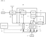
- FIG. 1 is a block diagram for describing a fuel-cell system according to an embodiment according to the present disclosure.
- FIG. 2 is a diagram for describing a bypass pipe shown in FIG. 1 .
- a fuel-cell system 100 may include a fuel-cell stack structure 110, a reformer 120, a burner 130, a first heat exchanger 140A, a second heat exchanger 140B, a first heater 150A, a second heater 150B, and a controller 160.
- the fuel-cell stack structure 110 may include one or more fuel-cell stacks operating at high temperatures.
- the fuel-cell stack structure 110 may include one or more solid oxide fuel-cell (SOFC) stacks, molten carbonate fuel-cell (MCFC) stacks, and the like operating at temperatures of about 500 °C or higher.
- SOFC solid oxide fuel-cell
- MCFC molten carbonate fuel-cell
- the fuel-cell stack structure 110 may generate electrical energy using oxygen in air and hydrogen in a reformed fuel gas. The oxygen-hydrogen reaction is exothermic, so that the fuel-cell stack structure 110 may release heat while generating electrical energy.
- the fuel-cell stack structure 110 may include a stack of planar cells or a bundle of cylindrical or flat tubular cells.
- the reformer 120 may convert at least a portion of the hydrocarbon fuel supplied from an external fuel supply 10 into hydrogen.
- the reformer 120 may include a steam reformer to convert the hydrocarbon fuel to hydrogen using steam as an oxidant, a partial oxidation reformer to convert the hydrocarbon fuel into hydrogen using oxygen as an oxidant, an auto-thermal reformer that converts the hydrocarbon fuel to hydrogen using both steam and oxygen as an oxidant, and a catalytic partial oxidation reformer for converting the hydrocarbon fuel to hydrogen via partial oxidation using a catalyst.
- the steam based reforming reaction in the steam reformer is an endothermic reaction
- the partial oxidation based reforming reaction and the catalytic partial oxidation based reforming reaction in the partial oxidation reformer and catalytic partial oxidation reformer respectively are exothermic reactions.
- the auto-thermal reforming reaction in the auto-thermal reformer is a balanced reaction.
- the steam reformer may be used as the reformer 120 in order to use the heat generation of the high-temperature operating fuel-cell stack structure 110 and to improve the hydrocarbon reforming efficiency.
- the reformer 120 may convert at least a portion of the fuel to hydrogen by reacting steam generated by heating water supplied from an external water supply (not shown) and fuel supplied from the fuel supply 10 with each other.
- a vaporizer may be disposed inside a second heat exchanger 140B to convert water into steam. Steam produced by the vaporizer and heated fuel from the fuel supply 10 may be mixed with each other to form a mixture which may be fed to the reformer 120.
- the reformer 120 may reform the fuel supplied from the fuel supply 10 and supply the hydrogen to the fuel-cell stack structure 110 for a time duration from a beginning time of the start-up mode of the fuel-cell stack structure 110 to the power generation mode in which the temperature of the fuel-cell stack structure 110 reaches about 600 °C to 700 ° C at which auto-thermal power generation is realized.
- the reformer 120 when the steam reformer is used as the reformer 120, the reformer 120 is supplied with air heated by the second heater 150B for a time duration from the start-up mode to a time when the temperature of the fuel-cell stack structure 110 reaches a predefined constant temperature.
- the internal temperature in the reformer 120 may be raised up via heat exchange between the reformer and the heated air, thereby improve the fuel reforming efficiency.
- the burner 130 may burn unreacted discharged fuel in the fuel supplied to the fuel-cell stack structure 110 and unreacted discharged air in the air supplied to the fuel-cell stack structure 110 to generate hot combusted gas and then may supply the hot combusted gas to the first heat exchanger 140A.
- the burner 130 may employ any known combustion apparatus with limitation, and thus detailed description thereof will be omitted.
- the first heat exchanger 140A heats the air provided from the external air supply 20 using the heat of the hot combusted gas provided from the burner 130. Then, the heated air may be provided to the fuel-cell stack structure 110. For example, the first heat exchanger 140A may heat the air via a heat exchange between the hot combusted gas provided from the burner 130 and the air provided from the air supply 20. To this end, the first heat exchanger 140 may be connected to a first air supply pipe 171 for supplying air from the air supply 20 to the fuel-cell stack.
- the first heat exchanger 140A may supply air to the fuel-cell stack. For example, for a duration from a beginning time of the start-up mode of the fuel-cell stack structure 110 to a time when the temperature of the fuel-cell stack structure 110 reaches the predefined temperature, the air heated by the first heater 150A may be supplied to the fuel-cell stack structure 110. Since the temperature of the fuel-cell stack structure 110 has reached the predefined temperature, the air heated by the first heat exchanger 140A may be supplied to the fuel-cell stack structure 110.
- the first heat exchanger 140A may supply the hot combusted gas to the second heat exchanger 140B.
- the second heat exchanger 140B may heat the fuel supplied from the fuel supply 10 using the heat of the hot combusted gas provided from the first heat exchanger 140A and then supply the heated fuel to the reformer 120.
- the second heat exchanger 140B may heat the fuel via heat exchange between the hot combusted gas provided from the first heat exchanger 140A and the fuel provided from the fuel supply 10.
- the combusted gas may be cooled after heating the fuel and then may be discharged to the outside.
- the second heat exchanger 140B may convert the water supplied from the external water supply into steam via heat exchange with the hot combusted gas supplied from the first heat exchanger 140A and the water supplied from the external water supply and may feed the converted steam to the reformer 120 together with the heated fuel.
- Each of the first and second heat exchangers 140A and 140B may employ any known heat exchanger without limitation, and thus a detailed description thereof will be omitted.
- the first heater 150A is installed on a second air supply pipe 172 for connecting the air supply 20 and the fuel-cell stack structure 110 with each other.
- the second air supply pipe 172 may be directly connected to the fuel-cell stack structure 110, or may be connected to a portion of the first air supply pipe 171 between the first heat exchanger 140A and the fuel-cell stack structure 110.
- the first heater 150A may heat the air to be supplied to the fuel-cell stack structure 110 via the second air supply pipe 172 for a duration from the beginning time of the start-up mode of the fuel-cell stack structure 110 to a time when the temperature of the fuel-cell stack structure 110 reaches the predefined constant temperature.
- the air heated by the first heat exchanger 140A and supplied to the fuel-cell stack structure 110 and the air heated by the first heater 150A and supplied to the fuel-cell stack structure 110 may react with hydrogen-containing reformed fuel supplied from the reformer 120 within the fuel-cell stack structure 110 to generate electrical energy.
- the second heater 150B is installed on a third air supply pipe 173 for connecting the air supply 20 and the reformer 120 with each other.
- the second heater 150B may heat the air to be supplied to the reformer 120 via the third air supply pipe 173 for a duration from the beginning time of the start-up mode of the fuel-cell stack structure 110 to a time when the temperature of the fuel-cell stack structure 110 reaches the predefined constant temperature.
- the reformer 120 may use the thermal energy of the air heated by the second heater 150B to raise the internal temperature thereof, thereby improving the reforming efficiency for the duration from the beginning time of the start-up mode of the fuel-cell stack structure 110 to a time when the temperature of the fuel-cell stack structure 110 reaches the predefined constant temperature.
- the first to third air supply pipes 171, 172, and 173 connected to the air supply 20 are provided with first to third valves 181, 182, and 183, respectively, to control the opening and closing thereof.
- the second and third valves 182 and 183 may close the second and third air supply pipes 172 and 173 respectively under the control operation of the controller 160 while the first valve 181 may open the first air supply pipe 171 under the control operation of the controller 160.
- the air heated by the first heat exchanger 140A may be supplied to the fuel-cell stack structure 110 via the first air supply pipe 171.
- the controller 160 blocks the first air supply pipe 171 using the first valve 181, and opens the second air supply pipe 172 using the second valve 182 to supply cooling air to the fuel-cell stack structure 110 while maintaining the first heater 150A at a stopped state. Further, the controller 160 opens the third air supply pipe 173 using the first valve 183 to supply cooling air to the reformer 120 while maintaining the second heater 150B at a stopped state.
- the hot air heated by the first and second heaters 150A and 150B may be supplied to the fuel-cell stack structure 110 and the reformer 120 for the duration from the beginning time of the start-up mode of the fuel-cell stack structure 110 to a time when the temperature of the fuel-cell stack structure 110 reaches the predefined constant temperature, the temperature of the entirety of the fuel-cell stack structure 110 may be raised uniformly and quickly.
- the time duration between the start-up mode of the fuel-cell stack structure 110 and the power generation mode thereof may be significantly reduced, as well as the thermal stability of the fuel-cell stack structure 110 may be improved.
- each of the first and second heaters 150A and 150B may employ an electrical heating device, a gas burner, or the like that may be easily turned on/off.
- the controller 160 controls the operation of each of the first and second heaters 150A and 150B based on the temperature of the fuel-cell stack structure 110.
- the controller 160 may use an electrical signal provided from a temperature sensor (not shown) disposed adj acent to the fuel-cell stack structure 110 to directly measure the temperature of the fuel-cell stack structure 110, or a temperature sensor (not shown) disposed on an air discharge pipe 175 to discharge the unreacted fuel from the fuel-cell stack structure 110 or a temperature sensor (not shown) disposed on an air discharge pipe 176 to discharge the unreacted air for indirectly measuring the temperature of the fuel-cell stack structure 110.
- the controller 160 may determine based on the electrical signal that the temperature of the fuel-cell stack structure 110 is lower than the predefined temperature, for example, a temperature between about 300 to 700 °C, the controller may turn on the first and second heaters 150A and 150B. When the temperature of the fuel-cell stack structure 110 is above the predefined temperature, the controller 160 may turn off the first and second heaters 150A and 150B.
- the fuel cell system 100 may further include a bypass pipe 174 and a fourth valve 184.
- the bypass pipe 174 may be connected to the air supply 20 and may extend to surround the fuel-cell stack 100.
- the bypass pipe 174 may include a first single pipe 174a connected to the air supply 20, a plurality of second pipes 174b branching from an end of the first single pipe 174a, and surrounding the fuel-cell stack structure 110, and a third single pipe 174c to which the plurality of second pipes 174a converge, wherein the third single pipe 174c is connected to the second heat exchanger 140B.
- the third single pipe 174c may be directly connected to the second heat exchanger 140B, or may be connected to a pipe for connecting the first heat exchanger 140A and the second heat exchanger 140B with each other.
- supplying air heated by the first and second heaters to the fuel-cell stack and the reformer during the start-up mode of the fuel-cell stack may allow the time duration from the start-up mode to the power generation mode to be reduced and allow the temperature distribution inside the fuel cell stack to be uniform, thereby improving the stability of the fuel cell stack.
- moving the cooling air via the bypass pipe or directly supplying the cooling air to the fuel-cell stack and reformer may allow the overall temperature of the fuel-cell stack to be lowered uniformly and quickly, thereby increasing the stability of the fuel-cell system.
Landscapes
- Engineering & Computer Science (AREA)
- Chemical & Material Sciences (AREA)
- Life Sciences & Earth Sciences (AREA)
- Manufacturing & Machinery (AREA)
- Sustainable Development (AREA)
- Sustainable Energy (AREA)
- Chemical Kinetics & Catalysis (AREA)
- Electrochemistry (AREA)
- General Chemical & Material Sciences (AREA)
- Combustion & Propulsion (AREA)
- Fuel Cell (AREA)
Claims (8)
- Brennstoffzellensystem (100), das Folgendes einschließt:eine Brennstoffzellenstapelstruktur (110), die einen oder mehrere Brennstoffzellenstapel einschließt; undeinen Reformer (120) zum Umwandeln zumindest eines Teils des Kohlenwasserstoffbrennstoffs in Wasserstoff und zum Zuführen des Wasserstoffs zur Brennstoffzellenstapelstruktur (110),wobei das Brennstoffzellensystem (100) weiter einschließt:einen ersten Wärmetauscher (140A), der mit einer ersten Luftzufuhrleitung (171) gekoppelt ist, um eine externe Luftzufuhr (20) und die Brennstoffzellenstapelstruktur (110) zu verbinden, wobei der erste Wärmetauscher (140A) zum Erhitzen von von der Luftzufuhr (20) zugeführter Luft über Wärmeaustausch und zum Zuführen der erhitzten Luft zur Brennstoffzellenstapelstruktur (110) konfiguriert ist;ein erstes Heizgerät (150A), das an einer zweiten Luftzufuhrleitung (172) zum Verbinden der Luftzufuhr (20) und der Brennstoffzellenstapelstruktur (110) installiert ist, wobei das erste Heizgerät (150A) zum Erhitzen von Luft konfiguriert ist, die dem Brennstoffzellenstapel über die zweite Luftzufuhrleitung zugeführt werden soll; undeine Steuereinheit (160), die zu Folgendem konfiguriert ist:wenn eine Temperatur der Brennstoffzellenstapelstruktur (110) niedriger ist als eine vordefinierte erste Temperatur, Aktivieren des ersten Heizgeräts (150A), um Luft zu erhitzen und die erhitzte Luft der Brennstoffzellenstapelstruktur (110) zuzuführen; undwenn die Temperatur der Brennstoffzellenstapelstruktur (110) über der ersten Temperatur und unter einer vorbestimmten zweiten Temperatur liegt, die höher als die erste Temperatur ist, Aktivieren des ersten Wärmetauschers (140A), um Luft zu erhitzen und die erhitzte Luft der Brennstoffzellenstapelstruktur (110) zuzuführen,ein zweites Heizgerät (150B), das an einer dritten Luftzufuhrleitung (173) zum Verbinden der Luftzufuhr (20) und des Reformers (120) installiert ist, wobei das zweite Heizgerät (150B) zum Erhitzen von Luft konfiguriert ist, die entlang der dritten Luftzufuhrleitung (173) strömt,
wobei, wenn die Temperatur der Brennstoffzellenstapelstruktur (110) unter der ersten Temperatur liegt, die Steuereinheit (160) weiter dazu konfiguriert ist, das zweite Heizgerät (150B) zu aktivieren, um die Luft zu erhitzen und die erhitzte Luft über die dritte Luftzufuhrleitung (173) dem Reformer (120) zuzuführen, um dadurch eine Temperatur im Inneren des Reformers (120) zu erhöhen,dadurch gekennzeichnet, dassdas Brennstoffzellensystem (100) weiter ein erstes bis drittes Ventil (181, 182 und 183) einschließt, die jeweils an der ersten bis dritten Luftzufuhrleitung (171, 172 und 173) installiert sind, um die erste bis dritte Luftzufuhrleitung jeweils zu öffnen und zu schließen,wobei die Steuereinheit (160) weiter dazu konfiguriert ist, das erste bis dritte Ventil (181, 182 und 183) und das erste und zweite Heizgerät (150A und 150B) so zu steuern, dass,wenn die Temperatur der Brennstoffzellenstapelstruktur (110) niedriger als die erste Temperatur ist, die durch das erste und zweite Heizgerät (150A und 150B) erhitzte Luft jeweils der Brennstoffzellenstapelstruktur (110) und dem Reformer (120) zugeführt wird,wenn die Temperatur der Brennstoffzellenstapelstruktur (110) in einem Bereich zwischen der ersten Temperatur und der zweiten, hohen Temperatur liegt, die durch den ersten Wärmetauscher (140A) erhitzte Luft der Brennstoffzellenstapelstruktur (110) zugeführt wird,wenn die Temperatur der Brennstoffzellenstapelstruktur (110) die zweite Temperatur überschreitet, das erste und zweite Heizgerät (150A und 150B) stoppen und die von der Luftzufuhr (20) zugeführte Luft der Brennstoffzellenstapelstruktur (110) und dem Reformer (120) in einem nicht erhitzten Zustand zugeführt wird. - Brennstoffzellensystem (100) nach Anspruch 1, wobei das Brennstoffzellensystem (100) weiter einen Brenner (130) zum Verbrennen von nicht umgesetztem Brennstoff und Luft, die aus der Brennstoffzellenstapelstruktur (110) ausgestoßen wird, einschließt,
wobei der erste Wärmetauscher (140A) dazu konfiguriert ist, die Luft unter Verwendung von heißem Verbrennungsgas, das vom Brenner (130) zugeführt wird, zu erhitzen. - Brennstoffzellensystem (100) nach Anspruch 2, wobei das Brennstoffzellensystem (100) weiter einen zweiten Wärmetauscher (140B) einschließt, der dazu konfiguriert ist, das heiße Verbrennungsgas vom ersten Wärmetauscher (140A) aufzunehmen und den von einer externen Brennstoffzufuhr (10) zugeführten Kohlenwasserstoffbrennstoff durch Wärmeaustausch mit dem heißen Verbrennungsgas zu erhitzen und den erhitzten Brennstoff dem Reformer (120) zuzuführen.
- Brennstoffzellensystem (100) nach Anspruch 3, wobei der zweite Wärmetauscher (140B) einen Verdampfer zum Umwandeln von Wasser in Dampf durch Wärmeaustausch mit dem Verbrennungsgas einschließt,wobei der zweite Wärmetauscher (140B) dazu konfiguriert ist, den erhitzten Kohlenwasserstoffbrennstoff und den vom Verdampfer erzeugten Dampf dem Reformer (120) zuzuführen,wobei der Reformer (120) dazu konfiguriert ist, unter Verwendung des Dampfs als Oxidationsmittel aus zumindest einem Teil des Kohlenwasserstoffbrennstoffs Wasserstoff zu erzeugen.
- Brennstoffzellensystem (100) nach Anspruch 1, wobei das Brennstoffzellensystem (100) weiter einen zweiten Wärmetauscher (140B) einschließt, der dazu konfiguriert ist, den von einer externen Brennstoffzufuhr (10) zugeführten Kohlenwasserstoffbrennstoff durch Wärmeaustausch zu erhitzen und den erhitzten Brennstoff dem Reformer (120) zuzuführen,
wobei der Reformer (120) dazu konfiguriert ist, die ihm zugeführte Luft über die dritte Luftzufuhrleitung (173) dem zweiten Wärmetauscher (140B) zuzuführen. - Brennstoffzellensystem (100) nach Anspruch 1, wobei sowohl das erste Heizgerät (150A) als auch das zweite Heizgerät (150B) eine elektrische Heizvorrichtung oder einen Gasbrenner einschließt.
- Brennstoffzellensystem (100) nach Anspruch 1, wobei das Brennstoffzellensystem (100) weiter einschließt:eine Bypassleitung (174), die mit der Luftzufuhr (20) verbunden ist und sich so erstreckt, dass sie die Brennstoffzellenstapelstruktur (110) umgibt; undein viertes Ventil (184), das an der Bypassleitung (174) installiert ist, um die Bypassleitung (174) zu öffnen und zu schließen,wobei die Steuereinheit (160) weiter dazu konfiguriert ist, das vierte Ventil (184) zu steuern, um die Bypassleitung (174) zu öffnen, so dass sich nicht erhitzte Luft durch die Bypassleitung bewegt, wenn die Temperatur der Brennstoffzellenstapelstruktur (110) über der zweiten Temperatur liegt.
- Brennstoffzellensystem (100) nach Anspruch 7, wobei die Bypassleitung (174) Folgendes einschließt:eine erste Einzelleitung (174a), die mit der Luftzufuhr (20) verbunden ist;eine Vielzahl von zweiten Leitungen (174b), die von einem Ende der ersten Einzelleitung (174a) abzweigen und die Brennstoffzellenstapelstruktur (110) umgeben; undeine dritte Einzelleitung (174c), in die die Vielzahl zweiter Leitungen (174a) zusammenläuft,wobei die dritte Einzelleitung (174c) direkt mit dem zweiten Wärmetauscher (140B) verbunden ist oder mit einer Leitung zum Verbinden des ersten Wärmetauschers (140A) und des zweiten Wärmetauschers (140B) miteinander verbunden ist.
Applications Claiming Priority (2)
| Application Number | Priority Date | Filing Date | Title |
|---|---|---|---|
| KR1020170063654A KR101958250B1 (ko) | 2017-05-23 | 2017-05-23 | 연료전지 시스템 |
| PCT/KR2018/005833 WO2018217005A1 (ko) | 2017-05-23 | 2018-05-23 | 연료전지 시스템 |
Publications (3)
| Publication Number | Publication Date |
|---|---|
| EP3633778A1 EP3633778A1 (de) | 2020-04-08 |
| EP3633778A4 EP3633778A4 (de) | 2021-03-10 |
| EP3633778B1 true EP3633778B1 (de) | 2024-12-25 |
Family
ID=64396903
Family Applications (1)
| Application Number | Title | Priority Date | Filing Date |
|---|---|---|---|
| EP18805611.3A Active EP3633778B1 (de) | 2017-05-23 | 2018-05-23 | Brennstoffzellensystem |
Country Status (3)
| Country | Link |
|---|---|
| EP (1) | EP3633778B1 (de) |
| KR (1) | KR101958250B1 (de) |
| WO (1) | WO2018217005A1 (de) |
Families Citing this family (9)
| Publication number | Priority date | Publication date | Assignee | Title |
|---|---|---|---|---|
| KR102676730B1 (ko) * | 2018-12-05 | 2024-06-19 | 현대자동차주식회사 | 연료전지의 발전 정지 모드 제어방법 및 제어시스템 |
| CN114365313B (zh) * | 2019-09-24 | 2024-07-02 | 日产自动车株式会社 | 燃料电池系统和燃料电池系统的控制方法 |
| CN112701316A (zh) * | 2019-10-23 | 2021-04-23 | 银隆新能源股份有限公司 | 一种燃料电池器件以及燃料电池控制系统、方法 |
| CN113782770B (zh) * | 2021-08-02 | 2023-07-07 | 佛山市飞驰汽车科技有限公司 | 一种燃料电池汽车的燃料电池 |
| US12224468B2 (en) * | 2021-10-12 | 2025-02-11 | Saudi Arabian Oil Companay | Solid oxide fuel cell systems and methods of operating solid oxide fuel cell systems |
| KR102821815B1 (ko) | 2021-10-29 | 2025-06-20 | 주식회사 화코리아 | 연료전지 발전장치 |
| US20250023074A1 (en) * | 2023-07-11 | 2025-01-16 | Hyaxiom, Inc. | Hydrogen power plant systems and methods of operation associated with cold start |
| AT527769B1 (de) * | 2023-12-05 | 2025-09-15 | Avl List Gmbh | Verfahren und Vorrichtung zum Betreiben eines Brennstoffzellensystems |
| AT528078A1 (de) * | 2024-03-06 | 2025-09-15 | Avl List Gmbh | Kontrollverfahren und Anordnung zum Kontrollieren einer Reformertemperatur |
Family Cites Families (9)
| Publication number | Priority date | Publication date | Assignee | Title |
|---|---|---|---|---|
| JP4000888B2 (ja) * | 2002-04-09 | 2007-10-31 | 日産自動車株式会社 | 改質型燃料電池システム |
| KR100774574B1 (ko) * | 2006-11-06 | 2007-11-09 | 한국에너지기술연구원 | 보조전원 유닛용 고체산화물 연료전지 발전시스템과 그기동방법 |
| JP5225604B2 (ja) * | 2007-04-09 | 2013-07-03 | 株式会社日立製作所 | 固体酸化物形燃料電池およびその発電方法 |
| KR100987823B1 (ko) * | 2009-01-12 | 2010-10-18 | 한국과학기술원 | 고체산화물 연료전지 시스템 |
| JP2011054515A (ja) * | 2009-09-04 | 2011-03-17 | Toshiba Corp | 純水素型燃料電池システム |
| DE102009060679B4 (de) * | 2009-12-28 | 2026-01-15 | Eberspächer Climate Control Systems GmbH & Co. KG | Betriebsverfahren für ein Brennstoffzellensystem |
| JP6089421B2 (ja) * | 2012-03-16 | 2017-03-08 | 日産自動車株式会社 | 燃料電池システム |
| CN105705226B (zh) * | 2013-11-06 | 2018-03-27 | 瓦特燃料电池公司 | 液体燃料催化部分氧化重整器和催化部分氧化重整方法 |
| JP6356481B2 (ja) * | 2014-05-15 | 2018-07-11 | 東京瓦斯株式会社 | 燃料電池システム |
-
2017
- 2017-05-23 KR KR1020170063654A patent/KR101958250B1/ko active Active
-
2018
- 2018-05-23 WO PCT/KR2018/005833 patent/WO2018217005A1/ko not_active Ceased
- 2018-05-23 EP EP18805611.3A patent/EP3633778B1/de active Active
Also Published As
| Publication number | Publication date |
|---|---|
| KR101958250B1 (ko) | 2019-07-04 |
| WO2018217005A1 (ko) | 2018-11-29 |
| EP3633778A1 (de) | 2020-04-08 |
| KR20180128288A (ko) | 2018-12-03 |
| EP3633778A4 (de) | 2021-03-10 |
Similar Documents
| Publication | Publication Date | Title |
|---|---|---|
| EP3633778B1 (de) | Brennstoffzellensystem | |
| CA2917783C (en) | Improved reaction efficiency in fuel cell systems and methods | |
| CN101918306B (zh) | 氢生成装置以及具备其的燃料电池系统 | |
| EP1826855B1 (de) | Brennstoffzellensystem und Verfahren zum Starten von Hochtemperatur-Polymerelektrolytmembranbrennstoffzellstapeln | |
| JP5643712B2 (ja) | 燃料電池モジュール | |
| CN101953010B (zh) | 间接内部转化型固体氧化物型燃料电池及其停止方法 | |
| US20210376361A1 (en) | Method and system for power generation with fuel cell | |
| CN109860660B (zh) | 一种高效固体氧化物燃料电池系统 | |
| WO2009119188A1 (ja) | 燃料電池システムとその負荷追従運転方法 | |
| KR102587217B1 (ko) | 연료전지 시스템 | |
| US6833209B2 (en) | Fuel-cell co-generation system, of electrical energy and hot water | |
| CN101981739B (zh) | 燃料电池系统及其负载跟踪运行方法 | |
| KR101205538B1 (ko) | 고체 산화물 연료 전지 시스템 | |
| JP2017183222A (ja) | 燃料電池システム | |
| JP5653834B2 (ja) | 燃料電池システム | |
| JP5643711B2 (ja) | 燃料電池モジュール | |
| JP5794206B2 (ja) | 燃料電池システム | |
| JP5675490B2 (ja) | 燃料電池モジュール | |
| KR100778207B1 (ko) | 전력변환장치의 폐열을 이용한 연료전지 시스템 | |
| EP3163660A1 (de) | Brennstoffzellenmodul mit erhöhter wärmeeffizienz und heizsystem damit sowie steuerungsverfahren dafür | |
| EP4546472A1 (de) | Wärmeverwaltung von elektrochemischen hochtemperaturvorrichtungen | |
| Hong et al. | Design and development of major balance of plant components in solid oxide fuel cell system | |
| KR101060283B1 (ko) | 연료 전지 시스템 및 연료 전지 시스템의 구동 방법 | |
| KR20260034211A (ko) | 열적 관리가 용이한 sofc 시스템 및 이의 운전 방법 | |
| KR20250103354A (ko) | 연료 전지 시스템 |
Legal Events
| Date | Code | Title | Description |
|---|---|---|---|
| STAA | Information on the status of an ep patent application or granted ep patent |
Free format text: STATUS: THE INTERNATIONAL PUBLICATION HAS BEEN MADE |
|
| PUAI | Public reference made under article 153(3) epc to a published international application that has entered the european phase |
Free format text: ORIGINAL CODE: 0009012 |
|
| STAA | Information on the status of an ep patent application or granted ep patent |
Free format text: STATUS: REQUEST FOR EXAMINATION WAS MADE |
|
| 17P | Request for examination filed |
Effective date: 20191120 |
|
| AK | Designated contracting states |
Kind code of ref document: A1 Designated state(s): AL AT BE BG CH CY CZ DE DK EE ES FI FR GB GR HR HU IE IS IT LI LT LU LV MC MK MT NL NO PL PT RO RS SE SI SK SM TR |
|
| AX | Request for extension of the european patent |
Extension state: BA ME |
|
| DAV | Request for validation of the european patent (deleted) | ||
| DAX | Request for extension of the european patent (deleted) | ||
| A4 | Supplementary search report drawn up and despatched |
Effective date: 20210204 |
|
| RIC1 | Information provided on ipc code assigned before grant |
Ipc: H01M 8/04664 20160101ALI20210129BHEP Ipc: H01M 8/04082 20160101ALI20210129BHEP Ipc: H01M 8/04746 20160101ALI20210129BHEP Ipc: H01M 8/0432 20160101ALI20210129BHEP Ipc: H01M 8/04228 20160101ALI20210129BHEP Ipc: H01M 8/04303 20160101ALI20210129BHEP Ipc: H01M 8/04302 20160101ALI20210129BHEP Ipc: H01M 8/04014 20160101AFI20210129BHEP Ipc: H01M 8/0662 20160101ALI20210129BHEP Ipc: H01M 8/04223 20160101ALI20210129BHEP Ipc: H01M 8/04007 20160101ALI20210129BHEP Ipc: H01M 8/0612 20160101ALI20210129BHEP Ipc: H01M 8/04225 20160101ALI20210129BHEP |
|
| RAP1 | Party data changed (applicant data changed or rights of an application transferred) |
Owner name: MICO POWER LTD |
|
| GRAP | Despatch of communication of intention to grant a patent |
Free format text: ORIGINAL CODE: EPIDOSNIGR1 |
|
| STAA | Information on the status of an ep patent application or granted ep patent |
Free format text: STATUS: GRANT OF PATENT IS INTENDED |
|
| RIC1 | Information provided on ipc code assigned before grant |
Ipc: H01M 8/04303 20160101ALI20240617BHEP Ipc: H01M 8/04302 20160101ALI20240617BHEP Ipc: H01M 8/04082 20160101ALI20240617BHEP Ipc: H01M 8/04223 20160101ALI20240617BHEP Ipc: H01M 8/04007 20160101ALI20240617BHEP Ipc: H01M 8/04228 20160101ALI20240617BHEP Ipc: H01M 8/04664 20160101ALI20240617BHEP Ipc: H01M 8/04225 20160101ALI20240617BHEP Ipc: H01M 8/0662 20160101ALI20240617BHEP Ipc: H01M 8/0612 20160101ALI20240617BHEP Ipc: H01M 8/04746 20160101ALI20240617BHEP Ipc: H01M 8/0432 20160101ALI20240617BHEP Ipc: H01M 8/04014 20160101AFI20240617BHEP |
|
| INTG | Intention to grant announced |
Effective date: 20240718 |
|
| GRAS | Grant fee paid |
Free format text: ORIGINAL CODE: EPIDOSNIGR3 |
|
| GRAA | (expected) grant |
Free format text: ORIGINAL CODE: 0009210 |
|
| STAA | Information on the status of an ep patent application or granted ep patent |
Free format text: STATUS: THE PATENT HAS BEEN GRANTED |
|
| AK | Designated contracting states |
Kind code of ref document: B1 Designated state(s): AL AT BE BG CH CY CZ DE DK EE ES FI FR GB GR HR HU IE IS IT LI LT LU LV MC MK MT NL NO PL PT RO RS SE SI SK SM TR |
|
| REG | Reference to a national code |
Ref country code: GB Ref legal event code: FG4D |
|
| REG | Reference to a national code |
Ref country code: CH Ref legal event code: EP |
|
| REG | Reference to a national code |
Ref country code: DE Ref legal event code: R096 Ref document number: 602018077961 Country of ref document: DE |
|
| REG | Reference to a national code |
Ref country code: IE Ref legal event code: FG4D |
|
| REG | Reference to a national code |
Ref country code: LT Ref legal event code: MG9D |
|
| PG25 | Lapsed in a contracting state [announced via postgrant information from national office to epo] |
Ref country code: HR Free format text: LAPSE BECAUSE OF FAILURE TO SUBMIT A TRANSLATION OF THE DESCRIPTION OR TO PAY THE FEE WITHIN THE PRESCRIBED TIME-LIMIT Effective date: 20241225 |
|
| PG25 | Lapsed in a contracting state [announced via postgrant information from national office to epo] |
Ref country code: FI Free format text: LAPSE BECAUSE OF FAILURE TO SUBMIT A TRANSLATION OF THE DESCRIPTION OR TO PAY THE FEE WITHIN THE PRESCRIBED TIME-LIMIT Effective date: 20241225 |
|
| PG25 | Lapsed in a contracting state [announced via postgrant information from national office to epo] |
Ref country code: BG Free format text: LAPSE BECAUSE OF FAILURE TO SUBMIT A TRANSLATION OF THE DESCRIPTION OR TO PAY THE FEE WITHIN THE PRESCRIBED TIME-LIMIT Effective date: 20241225 |
|
| PG25 | Lapsed in a contracting state [announced via postgrant information from national office to epo] |
Ref country code: NO Free format text: LAPSE BECAUSE OF FAILURE TO SUBMIT A TRANSLATION OF THE DESCRIPTION OR TO PAY THE FEE WITHIN THE PRESCRIBED TIME-LIMIT Effective date: 20250325 |
|
| PG25 | Lapsed in a contracting state [announced via postgrant information from national office to epo] |
Ref country code: GR Free format text: LAPSE BECAUSE OF FAILURE TO SUBMIT A TRANSLATION OF THE DESCRIPTION OR TO PAY THE FEE WITHIN THE PRESCRIBED TIME-LIMIT Effective date: 20250326 Ref country code: LV Free format text: LAPSE BECAUSE OF FAILURE TO SUBMIT A TRANSLATION OF THE DESCRIPTION OR TO PAY THE FEE WITHIN THE PRESCRIBED TIME-LIMIT Effective date: 20241225 |
|
| PG25 | Lapsed in a contracting state [announced via postgrant information from national office to epo] |
Ref country code: RS Free format text: LAPSE BECAUSE OF FAILURE TO SUBMIT A TRANSLATION OF THE DESCRIPTION OR TO PAY THE FEE WITHIN THE PRESCRIBED TIME-LIMIT Effective date: 20250325 |
|
| REG | Reference to a national code |
Ref country code: NL Ref legal event code: MP Effective date: 20241225 |
|
| PG25 | Lapsed in a contracting state [announced via postgrant information from national office to epo] |
Ref country code: NL Free format text: LAPSE BECAUSE OF FAILURE TO SUBMIT A TRANSLATION OF THE DESCRIPTION OR TO PAY THE FEE WITHIN THE PRESCRIBED TIME-LIMIT Effective date: 20241225 |
|
| REG | Reference to a national code |
Ref country code: AT Ref legal event code: MK05 Ref document number: 1754968 Country of ref document: AT Kind code of ref document: T Effective date: 20241225 |
|
| PG25 | Lapsed in a contracting state [announced via postgrant information from national office to epo] |
Ref country code: SM Free format text: LAPSE BECAUSE OF FAILURE TO SUBMIT A TRANSLATION OF THE DESCRIPTION OR TO PAY THE FEE WITHIN THE PRESCRIBED TIME-LIMIT Effective date: 20241225 |
|
| PG25 | Lapsed in a contracting state [announced via postgrant information from national office to epo] |
Ref country code: PL Free format text: LAPSE BECAUSE OF FAILURE TO SUBMIT A TRANSLATION OF THE DESCRIPTION OR TO PAY THE FEE WITHIN THE PRESCRIBED TIME-LIMIT Effective date: 20241225 |
|
| PGFP | Annual fee paid to national office [announced via postgrant information from national office to epo] |
Ref country code: DE Payment date: 20250325 Year of fee payment: 8 |
|
| PG25 | Lapsed in a contracting state [announced via postgrant information from national office to epo] |
Ref country code: ES Free format text: LAPSE BECAUSE OF FAILURE TO SUBMIT A TRANSLATION OF THE DESCRIPTION OR TO PAY THE FEE WITHIN THE PRESCRIBED TIME-LIMIT Effective date: 20241225 |
|
| PG25 | Lapsed in a contracting state [announced via postgrant information from national office to epo] |
Ref country code: IS Free format text: LAPSE BECAUSE OF FAILURE TO SUBMIT A TRANSLATION OF THE DESCRIPTION OR TO PAY THE FEE WITHIN THE PRESCRIBED TIME-LIMIT Effective date: 20250425 |
|
| PG25 | Lapsed in a contracting state [announced via postgrant information from national office to epo] |
Ref country code: PT Free format text: LAPSE BECAUSE OF FAILURE TO SUBMIT A TRANSLATION OF THE DESCRIPTION OR TO PAY THE FEE WITHIN THE PRESCRIBED TIME-LIMIT Effective date: 20250428 |
|
| PG25 | Lapsed in a contracting state [announced via postgrant information from national office to epo] |
Ref country code: EE Free format text: LAPSE BECAUSE OF FAILURE TO SUBMIT A TRANSLATION OF THE DESCRIPTION OR TO PAY THE FEE WITHIN THE PRESCRIBED TIME-LIMIT Effective date: 20241225 |
|
| PG25 | Lapsed in a contracting state [announced via postgrant information from national office to epo] |
Ref country code: AT Free format text: LAPSE BECAUSE OF FAILURE TO SUBMIT A TRANSLATION OF THE DESCRIPTION OR TO PAY THE FEE WITHIN THE PRESCRIBED TIME-LIMIT Effective date: 20241225 Ref country code: RO Free format text: LAPSE BECAUSE OF FAILURE TO SUBMIT A TRANSLATION OF THE DESCRIPTION OR TO PAY THE FEE WITHIN THE PRESCRIBED TIME-LIMIT Effective date: 20241225 |
|
| PG25 | Lapsed in a contracting state [announced via postgrant information from national office to epo] |
Ref country code: SK Free format text: LAPSE BECAUSE OF FAILURE TO SUBMIT A TRANSLATION OF THE DESCRIPTION OR TO PAY THE FEE WITHIN THE PRESCRIBED TIME-LIMIT Effective date: 20241225 |
|
| PG25 | Lapsed in a contracting state [announced via postgrant information from national office to epo] |
Ref country code: CZ Free format text: LAPSE BECAUSE OF FAILURE TO SUBMIT A TRANSLATION OF THE DESCRIPTION OR TO PAY THE FEE WITHIN THE PRESCRIBED TIME-LIMIT Effective date: 20241225 |
|
| PG25 | Lapsed in a contracting state [announced via postgrant information from national office to epo] |
Ref country code: IT Free format text: LAPSE BECAUSE OF FAILURE TO SUBMIT A TRANSLATION OF THE DESCRIPTION OR TO PAY THE FEE WITHIN THE PRESCRIBED TIME-LIMIT Effective date: 20241225 |
|
| PG25 | Lapsed in a contracting state [announced via postgrant information from national office to epo] |
Ref country code: SE Free format text: LAPSE BECAUSE OF FAILURE TO SUBMIT A TRANSLATION OF THE DESCRIPTION OR TO PAY THE FEE WITHIN THE PRESCRIBED TIME-LIMIT Effective date: 20241225 |
|
| REG | Reference to a national code |
Ref country code: DE Ref legal event code: R097 Ref document number: 602018077961 Country of ref document: DE |
|
| PG25 | Lapsed in a contracting state [announced via postgrant information from national office to epo] |
Ref country code: DK Free format text: LAPSE BECAUSE OF FAILURE TO SUBMIT A TRANSLATION OF THE DESCRIPTION OR TO PAY THE FEE WITHIN THE PRESCRIBED TIME-LIMIT Effective date: 20241225 |
|
| PLBE | No opposition filed within time limit |
Free format text: ORIGINAL CODE: 0009261 |
|
| STAA | Information on the status of an ep patent application or granted ep patent |
Free format text: STATUS: NO OPPOSITION FILED WITHIN TIME LIMIT |
|
| REG | Reference to a national code |
Ref country code: CH Ref legal event code: L10 Free format text: ST27 STATUS EVENT CODE: U-0-0-L10-L00 (AS PROVIDED BY THE NATIONAL OFFICE) Effective date: 20251105 |
|
| 26N | No opposition filed |
Effective date: 20250926 |
|
| REG | Reference to a national code |
Ref country code: CH Ref legal event code: H13 Free format text: ST27 STATUS EVENT CODE: U-0-0-H10-H13 (AS PROVIDED BY THE NATIONAL OFFICE) Effective date: 20251223 |
|
| PG25 | Lapsed in a contracting state [announced via postgrant information from national office to epo] |
Ref country code: LU Free format text: LAPSE BECAUSE OF NON-PAYMENT OF DUE FEES Effective date: 20250523 |
|
| PG25 | Lapsed in a contracting state [announced via postgrant information from national office to epo] |
Ref country code: CH Free format text: LAPSE BECAUSE OF NON-PAYMENT OF DUE FEES Effective date: 20250531 |
|
| GBPC | Gb: european patent ceased through non-payment of renewal fee |
Effective date: 20250523 |
|
| REG | Reference to a national code |
Ref country code: BE Ref legal event code: MM Effective date: 20250531 |
|
| PG25 | Lapsed in a contracting state [announced via postgrant information from national office to epo] |
Ref country code: MC Free format text: LAPSE BECAUSE OF FAILURE TO SUBMIT A TRANSLATION OF THE DESCRIPTION OR TO PAY THE FEE WITHIN THE PRESCRIBED TIME-LIMIT Effective date: 20241225 |
|
| PG25 | Lapsed in a contracting state [announced via postgrant information from national office to epo] |
Ref country code: GB Free format text: LAPSE BECAUSE OF NON-PAYMENT OF DUE FEES Effective date: 20250523 |
|
| PG25 | Lapsed in a contracting state [announced via postgrant information from national office to epo] |
Ref country code: IE Free format text: LAPSE BECAUSE OF NON-PAYMENT OF DUE FEES Effective date: 20250523 |
|
| PG25 | Lapsed in a contracting state [announced via postgrant information from national office to epo] |
Ref country code: BE Free format text: LAPSE BECAUSE OF NON-PAYMENT OF DUE FEES Effective date: 20250531 |
|
| PG25 | Lapsed in a contracting state [announced via postgrant information from national office to epo] |
Ref country code: FR Free format text: LAPSE BECAUSE OF NON-PAYMENT OF DUE FEES Effective date: 20250531 |