EP3633761A1 - Battery pack for mounting on vehicle - Google Patents
Battery pack for mounting on vehicle Download PDFInfo
- Publication number
- EP3633761A1 EP3633761A1 EP18809266.2A EP18809266A EP3633761A1 EP 3633761 A1 EP3633761 A1 EP 3633761A1 EP 18809266 A EP18809266 A EP 18809266A EP 3633761 A1 EP3633761 A1 EP 3633761A1
- Authority
- EP
- European Patent Office
- Prior art keywords
- case
- gas release
- battery modules
- pack
- gas
- Prior art date
- Legal status (The legal status is an assumption and is not a legal conclusion. Google has not performed a legal analysis and makes no representation as to the accuracy of the status listed.)
- Granted
Links
Images



Classifications
-
- H—ELECTRICITY
- H01—ELECTRIC ELEMENTS
- H01M—PROCESSES OR MEANS, e.g. BATTERIES, FOR THE DIRECT CONVERSION OF CHEMICAL ENERGY INTO ELECTRICAL ENERGY
- H01M50/00—Constructional details or processes of manufacture of the non-active parts of electrochemical cells other than fuel cells, e.g. hybrid cells
- H01M50/30—Arrangements for facilitating escape of gases
- H01M50/394—Gas-pervious parts or elements
-
- B—PERFORMING OPERATIONS; TRANSPORTING
- B60—VEHICLES IN GENERAL
- B60L—PROPULSION OF ELECTRICALLY-PROPELLED VEHICLES; SUPPLYING ELECTRIC POWER FOR AUXILIARY EQUIPMENT OF ELECTRICALLY-PROPELLED VEHICLES; ELECTRODYNAMIC BRAKE SYSTEMS FOR VEHICLES IN GENERAL; MAGNETIC SUSPENSION OR LEVITATION FOR VEHICLES; MONITORING OPERATING VARIABLES OF ELECTRICALLY-PROPELLED VEHICLES; ELECTRIC SAFETY DEVICES FOR ELECTRICALLY-PROPELLED VEHICLES
- B60L50/00—Electric propulsion with power supplied within the vehicle
- B60L50/50—Electric propulsion with power supplied within the vehicle using propulsion power supplied by batteries or fuel cells
- B60L50/60—Electric propulsion with power supplied within the vehicle using propulsion power supplied by batteries or fuel cells using power supplied by batteries
- B60L50/64—Constructional details of batteries specially adapted for electric vehicles
-
- B—PERFORMING OPERATIONS; TRANSPORTING
- B60—VEHICLES IN GENERAL
- B60L—PROPULSION OF ELECTRICALLY-PROPELLED VEHICLES; SUPPLYING ELECTRIC POWER FOR AUXILIARY EQUIPMENT OF ELECTRICALLY-PROPELLED VEHICLES; ELECTRODYNAMIC BRAKE SYSTEMS FOR VEHICLES IN GENERAL; MAGNETIC SUSPENSION OR LEVITATION FOR VEHICLES; MONITORING OPERATING VARIABLES OF ELECTRICALLY-PROPELLED VEHICLES; ELECTRIC SAFETY DEVICES FOR ELECTRICALLY-PROPELLED VEHICLES
- B60L50/00—Electric propulsion with power supplied within the vehicle
- B60L50/50—Electric propulsion with power supplied within the vehicle using propulsion power supplied by batteries or fuel cells
- B60L50/60—Electric propulsion with power supplied within the vehicle using propulsion power supplied by batteries or fuel cells using power supplied by batteries
- B60L50/66—Arrangements of batteries
-
- H—ELECTRICITY
- H01—ELECTRIC ELEMENTS
- H01M—PROCESSES OR MEANS, e.g. BATTERIES, FOR THE DIRECT CONVERSION OF CHEMICAL ENERGY INTO ELECTRICAL ENERGY
- H01M50/00—Constructional details or processes of manufacture of the non-active parts of electrochemical cells other than fuel cells, e.g. hybrid cells
- H01M50/20—Mountings; Secondary casings or frames; Racks, modules or packs; Suspension devices; Shock absorbers; Transport or carrying devices; Holders
- H01M50/204—Racks, modules or packs for multiple batteries or multiple cells
- H01M50/207—Racks, modules or packs for multiple batteries or multiple cells characterised by their shape
- H01M50/209—Racks, modules or packs for multiple batteries or multiple cells characterised by their shape adapted for prismatic or rectangular cells
-
- H—ELECTRICITY
- H01—ELECTRIC ELEMENTS
- H01M—PROCESSES OR MEANS, e.g. BATTERIES, FOR THE DIRECT CONVERSION OF CHEMICAL ENERGY INTO ELECTRICAL ENERGY
- H01M50/00—Constructional details or processes of manufacture of the non-active parts of electrochemical cells other than fuel cells, e.g. hybrid cells
- H01M50/20—Mountings; Secondary casings or frames; Racks, modules or packs; Suspension devices; Shock absorbers; Transport or carrying devices; Holders
- H01M50/249—Mountings; Secondary casings or frames; Racks, modules or packs; Suspension devices; Shock absorbers; Transport or carrying devices; Holders specially adapted for aircraft or vehicles, e.g. cars or trains
-
- H—ELECTRICITY
- H01—ELECTRIC ELEMENTS
- H01M—PROCESSES OR MEANS, e.g. BATTERIES, FOR THE DIRECT CONVERSION OF CHEMICAL ENERGY INTO ELECTRICAL ENERGY
- H01M50/00—Constructional details or processes of manufacture of the non-active parts of electrochemical cells other than fuel cells, e.g. hybrid cells
- H01M50/30—Arrangements for facilitating escape of gases
-
- H—ELECTRICITY
- H01—ELECTRIC ELEMENTS
- H01M—PROCESSES OR MEANS, e.g. BATTERIES, FOR THE DIRECT CONVERSION OF CHEMICAL ENERGY INTO ELECTRICAL ENERGY
- H01M2220/00—Batteries for particular applications
- H01M2220/20—Batteries in motive systems, e.g. vehicle, ship, plane
-
- Y—GENERAL TAGGING OF NEW TECHNOLOGICAL DEVELOPMENTS; GENERAL TAGGING OF CROSS-SECTIONAL TECHNOLOGIES SPANNING OVER SEVERAL SECTIONS OF THE IPC; TECHNICAL SUBJECTS COVERED BY FORMER USPC CROSS-REFERENCE ART COLLECTIONS [XRACs] AND DIGESTS
- Y02—TECHNOLOGIES OR APPLICATIONS FOR MITIGATION OR ADAPTATION AGAINST CLIMATE CHANGE
- Y02E—REDUCTION OF GREENHOUSE GAS [GHG] EMISSIONS, RELATED TO ENERGY GENERATION, TRANSMISSION OR DISTRIBUTION
- Y02E60/00—Enabling technologies; Technologies with a potential or indirect contribution to GHG emissions mitigation
- Y02E60/10—Energy storage using batteries
-
- Y—GENERAL TAGGING OF NEW TECHNOLOGICAL DEVELOPMENTS; GENERAL TAGGING OF CROSS-SECTIONAL TECHNOLOGIES SPANNING OVER SEVERAL SECTIONS OF THE IPC; TECHNICAL SUBJECTS COVERED BY FORMER USPC CROSS-REFERENCE ART COLLECTIONS [XRACs] AND DIGESTS
- Y02—TECHNOLOGIES OR APPLICATIONS FOR MITIGATION OR ADAPTATION AGAINST CLIMATE CHANGE
- Y02T—CLIMATE CHANGE MITIGATION TECHNOLOGIES RELATED TO TRANSPORTATION
- Y02T10/00—Road transport of goods or passengers
- Y02T10/60—Other road transportation technologies with climate change mitigation effect
- Y02T10/70—Energy storage systems for electromobility, e.g. batteries
Definitions
- the present invention relates to an on-vehicle battery pack.
- Battery packs mounted on vehicles such as electric vehicles include unit cells housed in a pack case. If a gas is generated inside a unit cell due to some reason and the internal pressure of the unit cell abnormally rises, the gas is discharged from the unit cell into the pack case (see Patent Literature 1).
- Patent Literature 1 Japanese Patent Application Publication No. 2008-251308
- the gas discharged from the unit cell is hot. Since the gas rises directly to an upper portion of the inside of the pack case, the top of the pack case becomes hot. For this reason, on-vehicle components disposed in proximity to the top of the pack case, e.g., resin components, a spare tire, and so on may possibly be thermally deteriorated.
- An object of the present invention is to provide an on-vehicle battery pack capable of keeping the top of its pack case from becoming hot as a result of discharge of a gas from a unit cell.
- An on-vehicle battery pack includes: a battery module with a unit cell housed in a module case, a specific plane of the module case being set as a gas release plane from which to release a gas discharged from the unit cell; and a pack case in which the battery module is housed; and a restriction plate which keeps the gas released from the gas release plane from rising directly to an upper portion of inside of the pack case.
- the battery module is housed with the gas release plane facing an inner surface of a sidewall portion of the pack case with a space therebetween.
- the restriction plate includes a first plate portion protruding toward the sidewall portion at a height position higher than at least an upper edge of the gas release plane, and a second plate portion extending downwards in the space continuously from a front edge of the first plate portion in a direction in which the first plate portion protrudes.
- the X, Y, and Z axes given in some drawings indicate the orientation of an on-vehicle battery pack.
- the X axis represents the vehicle front-rear direction (the rear side of the vehicle is the positive side while the front side is the negative side)
- the Y axis represents the vehicle width direction (right-left direction)
- the Z axis represents the vertical direction.
- Fig. 1 is a perspective view illustrating a main part of an on-vehicle battery pack 10.
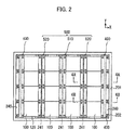
- Fig. 2 is a plan view illustrating the battery pack 10.
- Fig. 3 is a cross-sectional view schematically illustrating the main part of the battery pack 10.
- Fig. 4A is a cross-sectional view along line 4A-4A in Fig. 2 .
- Fig. 4B is a cross-sectional view along line 4B-4B in Fig. 2 .
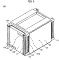
- Fig. 6 is a perspective view illustrating a battery module 100.
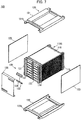
- Fig. 7 is a perspective view illustrating the battery module 100 illustrated in Fig. 6 with some parts disassembled.
- the on-vehicle battery pack 10 includes: battery modules 100 with unit cells 110 housed in a module case 120, specific planes of the module case 120 being set as gas release planes 140 from which to release a gas discharged from any of the unit cells 110; and a pack case 200 in which the battery modules 100 are housed.
- the battery pack 10 further includes restriction plates 400 that prevent the gas released from the gas release planes 140 from rising directly to the upper portion of the inside of the pack case 200.
- the rise of the gas directly to an upper portion of the inside of the pack case 200 means that the gas rises without descending after being released from the gas release planes 140.
- Each restriction plate 400 includes: a first plate portion 410 protruding toward the sidewall portion 201 at a height position higher than at least upper edges 143 of the gas release planes 140; and a second plate portion 420 extending downwards in the space 240 continuously from a front edge 411 of the first plate portion 410 in the direction in which the first plate portion 410 protrudes.
- a plurality of battery modules 100 are housed in the pack case 200 side by side in both the vehicle width direction (Y axis) and the vehicle front-rear direction (X axis).
- the rows of battery modules 100 arrayed along the vehicle width direction will be referred to as the first row, the second row, the third row, and the fourth row in this order from the front side of the vehicle (the left side in Figs. 2 and 3 ). Details will now be described.
- a stack 110S as a plurality of flat unit cells 110 stacked on one another is housed in the module case 120.
- a pair of opposite planes of the module case 120 are set as the gas release planes 140.
- the plane on the near side to the left and the plane on the far side to the right are the gas release planes 140.
- a gas discharged from any of the unit cells 110 is released from the gas release plane 140 on the near side to the left and the gas release plane 140 on the far side to the right.
- the illustrated module case 120 is formed of four plate members and functions also as a pressing unit that presses the stack 110S.
- the plurality of unit cells 110 are electrically connected to each other by a bus bar unit 130 in the state of being pressed by the module case 120.
- Each unit cell 110 is, for example, a lithium-ion secondary battery including: a cell body of a rectangular shape in a plan view obtained, for example, by sealing a power generation element formed by stacking a positive plate and a negative plate with a separator therebetween in a bag-shaped exterior member made of a laminate film along with an electrolyte; and positive and negative electrode tabs as positive and negative output terminals connected to the power generation element inside the exterior member and led out from one side of the cell body to the outside of the exterior member.
- Each unit cell 110 is stacked in a state where the side of the cell body with the electrode tabs is supported by a pair of first spacers 114 while the side of the cell body without the electrode tabs is supported by a pair of second spacers 115.
- the module case 120 includes an upper pressing plate 121 and a lower pressing plate 122 that press the power generation elements (not illustrated) of the unit cells 110 in the stack 110S from the top and bottom, and a pair of side plates 123 that fix the upper pressing plate 121 and the lower pressing plate 122 in the state of pressing the stack 110S.
- the upper pressing plate 121 includes locating holes 121b to insert fastening bolts for fixing the battery module 100 to the pack case 200.
- the locating holes 121b are through-holes and bored in the four corners of the upper pressing plate 121.
- the lower pressing plate 122 includes locating holes 122b to insert fastening bolts, like the upper pressing plate 121.
- the pair of side plates 123 are welded to the upper pressing plate 121 and the lower pressing plate 122.
- the constituent material of the module case 120 is not particularly limited as long as the material is capable of withstanding a hot gas discharged from any of the unit cells 110.
- the module case 120 can be made from stainless steel or the like.
- the bus bar unit 130 includes: bus bars 132 electrically connecting the electrode tabs of the unit cells 110 arranged next to each other in the vertical direction; bus bar holders 131 holding the plurality of bus bars 132 together; and a protection cover 135 protecting the bus bars 132.
- the bus bar unit 130 further includes: an anode-side terminal 133 through which the anode-side end of the plurality of electrically connected unit cells 110 is exposed to an external input-output terminal; and a cathode-side terminal 134 through which the cathode-side end is exposed to an external input-output terminal.
- the pack case 200 includes: an upper case 220 in a bottomed box shape opening on the lower side; a lower case 210 in a bottomed box shape opening on the upper side; and a sealing portion 230 at which the outer peripheries of the opening portions of the upper and lower cases 220 and 210 are connected with a sealing member 231 therebetween.
- the lower case 210 is bolted to a bottom part of the vehicle body not illustrated.
- the upper case 220 is bolted at its periphery to the periphery of the lower case 210.
- the sealing member 231 is made of a rubber material, for example.
- a weak portion (not illustrated) is provided at a part of the sealing portion 230.
- a gas release valve that opens when a set pressure is reached or exceeded may be provided to the pack case 200 instead of forming the weak portion at a part of the sealing portion 230.
- 16 battery modules 100 in total are housed in the pack case 200 such that 4 rows of 4 battery modules 100 arrayed in the vehicle width direction are arranged side by side in the vehicle front-rear direction.
- a pair of opposite planes of the module case 120 are set as the gas release planes 140.
- first gas release plane 141 the opening plane on the side without the bus bar unit 130
- second gas release plane 142 the opening plane on the side with the bus bar unit 130
- the battery modules 100 in the first row are housed with the first gas release plane 141 facing the inner surface of the sidewall portion 201 of the pack case 200 on the left side in Figs. 2 and 3 with a space 240 therebetween.
- the battery modules 100 in the fourth row are housed with the first gas release plane 141 facing the inner surface of the sidewall portion 201 of the pack case 200 on the right side in Figs. 2 and 3 with a space 240 therebetween.
- the battery modules 100 in the first row and the second row are disposed with their second gas release planes 142 facing each other with a clearance 241 therebetween.
- the battery modules 100 in the third row and the fourth row are disposed with their second gas release planes 142 facing each other with a clearance 241 therebetween.
- the battery modules 100 in the second row and the third row are disposed with their first gas release planes 141 facing each other with a clearance 241 therebetween.
- Some battery modules 100 lying adjacent to each other in the vehicle front-rear direction have different height dimensions (Z axis) due to the difference in number of unit cells 110 stacked.
- the battery modules 100 in the first row and the fourth row have a larger number of unit cells 110 stacked than the battery modules 100 in the second row and the third row. For this reason, the battery modules 100 in the first row and the fourth row have a larger height dimension than the battery modules 100 in the second row and the third row (see ⁇ h in Fig. 1 ).
- the battery modules 100 in the second row and the third row have the same number of unit cells 110 stacked and have the same height dimension.
- the restriction plates 400 are attached to the battery modules 100 in the first row and the fourth row.
- Each restriction plate 400 includes: the first plate portion 410, protruding toward the sidewall portion 201 at a height position higher than at least the upper edge 143 of the first gas release plane 141; and the second plate portion 420, extending downwards in the space 240 continuously from the front edge 411 of the first plate portion 410 in the direction in which the first plate portion 410 protrudes.
- the first plate portion 410 is fixed to the upper surface of the module case 120 with bolts or the like.
- the constituent material of the restriction plate 400 is not particularly limited as long as the material is capable of withstanding a hot gas discharged from any of the unit cells 110.
- the restriction plate 400 can be made from stainless steel or the like.
- the second plate portion 420 of each restriction plate 400 extends to a position lower than the sealing portion 230 in order to prevent a gas released from the first gas release plane 141 from directly hitting the sealing portion 230.
- each restriction plate 400 is fixed to the pack case 200.
- the restriction plate 400 includes a fixing piece 430 protruding toward the sidewall portion 201 from the lower edge of the second plate portion 420.
- a protrusion 202 on which to place the fixing piece 430 is formed on the inner surface of the sidewall portion 201 of the lower case 210.
- the fixing piece 430 is fastened to the protrusion 202 with bolts or the like not illustrated. As a result, the restriction plate 400 is fixed to the pack case 200.
- the first row and the fourth row include a plurality of battery modules 100 (four in each row in the illustrated example) disposed side by side in the pack case 200.
- each of the battery modules 100 is equipped with a restriction plate 400, and these restriction plates 400 are connected to each other.
- being "connected to each other” includes a state in which a restriction plate 400 is formed as a single integrated body as illustrated, and also a state in which separately formed restriction plates 400 are bolted or welded together.
- the first gas release planes 141 of all four battery modules 100 in the first row face the inner surface of one sidewall portion 201 (the left sidewall portion 201).
- the first gas release planes 141 of all four battery modules 100 in the fourth row face the inner surface of one sidewall portion 201 (the right sidewall portion 201).
- a clearance 241 is present between the first row and the second row, between the second row and the third row, and between the third row and the fourth row.
- the battery pack 10 further includes cover members 500 closing upper end openings 242 formed at the upper ends of the clearances 241.
- the cover members 500 in this embodiment are a first cover member 510 closing the upper end opening 242 between the second row and the third row, and second cover members 520 closing the upper end opening 242 between the first row and the second row and the upper end opening 242 between the third row and the fourth row.
- the battery modules 100 in the second row and the third row have the same height dimension. For this reason, the first cover member 510 has a substantially flat plate shape.
- each second cover member 520 includes a third plate portion 521 extending upwards and facing the second gas release planes 142 of the taller ones of the battery modules 100.
- the constituent material of the cover members 500 is not particularly limited as long as the material is capable of withstanding a hot gas discharged from any of the unit cells 110.
- the cover members 500 can be made from stainless steel or the like.
- a plurality of battery modules 100 are disposed side by side in the pack case 200.
- each of the battery modules 100 is equipped with a cover member(s) 500, and these cover members 500 are connected to each other.
- being “connected to each other” includes a state in which a cover member 500 is formed as a single integrated body as illustrated, and also a state in which separately formed cover members 500 are bolted or welded together.
- the gas released from the first gas release plane 141 is prevented from rising directly to the upper portion of the inside of the pack case 200 by the first plate portion 410 of the restriction plate 400.
- the gas flows downwards along the second plate portion 420.
- the gas Upon reaching the lower end of the second plate portion 420, the gas reverses its flow direction to an upward direction and flows toward the upper portion of the inside of the pack case 200 along the sidewall portion 201 of the pack case 200 (see an arrow in Fig. 4A ).
- the gas released from the second gas release plane 142 is prevented from rising directly to the upper portion of the inside of the pack case 200 since the upper end opening 242 of the clearance 241 is closed by the second cover member 520.
- the second cover member 520 includes the third plate portion 521, thereby reliably preventing the gas from rising directly to the upper portion although the adjacent battery modules 100 have different height dimensions. The gas then passes other portions to flow to the upper portion of the inside of the pack case 200 (see an arrow in Fig. 4A ).
- the gas released from the first gas release plane 141 is prevented from rising directly to the upper portion of the inside of the pack case 200 since the upper end opening 242 of the clearance 241 is closed by the first cover member 510.
- the gas released from the second gas release plane 142 is prevented from rising directly to the upper portion of the inside of the pack case 200 since the upper end opening 242 of the clearance 241 is closed by the second cover member 520.
- the hot gas does not directly hit the upper case 220.
- the gas temperature drops to a certain extent. This keeps the top of the pack case 200 from becoming hot.
- an on-vehicle component 600 (see Fig. 3 ) disposed in proximity to the top of the pack case 200 can be prevented from being thermally deteriorated.
- the on-vehicle component 600 is, for example, a resin component, a spare tire, or the like.
- the 16 battery modules 100 in total, housed in the pack case 200, are coupled to each other by the restriction plates 400, the first cover member 510, and the second cover members 520. For this reason, the adjacent battery modules 100 are kept from moving relative to each other in both the vehicle width direction and the vehicle front-rear direction. Since the restriction plates 400 are fixed to the pack case 200, the plurality of battery modules 100 are kept from moving inside the pack case 200.
- the on-vehicle battery pack 10 in this embodiment includes the restriction plates 400, which keep a gas released from a gas release plane 140 from rising directly to the upper portion of the inside of the pack case 200.
- Some battery modules 100 are housed with a gas release plane 140 facing the inner surface of a sidewall portion 201 of the pack case 200 with a space 240 therebetween.
- Each restriction plate 400 includes: the first plate portion 410, protruding toward the sidewall portion 201 at a height position higher than at least the upper edge 143 of the gas release plane 140; and the second plate portion 420, extending downwards in the space 240 continuously from the front edge 411 of the first plate portion 410 in the direction in which the first plate portion 410 protrudes.
- the pack case 200 includes the upper case 220, the lower case 210, and the sealing portion 230, and the second plate portion 420 of each restriction plate 400 extends to a position lower than the sealing portion 230.
- the restriction plates 400 are fixed to the pack case 200.
- the restriction plates 400 also have the function of supporting the battery modules 100. This makes it possible to omit dedicated components only having the function of supporting the battery modules 100. By reducing the number of components, the cost and weight of the battery pack 10 can be reduced.
- the plurality of battery modules 100 are each equipped with a restriction plate 400, and these restriction plates 400 are connected to each other.
- the adjacent battery modules 100 are kept from moving relative to each other.
- a gas release plane 140 of every one of the plurality of battery modules 100 faces the inner surface of one sidewall portion 201.
- the plurality of battery modules 100 have the same gas discharge direction. This makes it possible to simplify the shape of each restriction plate 400 and also reduce the number of restriction plates 400 to be installed. Accordingly, the cost and weight of the battery pack 10 can be reduced.
- each battery module 100 a pair of opposite planes of the module case 120 are set as the gas release planes 140 (141, 142).
- the plurality of battery modules 100 are disposed with their gas release planes 140 facing each other with a clearance 241 therebetween.
- the battery pack 10 further includes the cover members 500, closing the upper end openings 242 formed at the upper ends of the clearances 241.
- Some adjacent battery modules 100 have different height dimensions due to the difference in number of unit cells 110 stacked, and some cover members 500 include the third plate portion 521, extending upwards and facing a gas release plane 140 of the taller one of the battery modules 100.
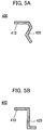
- Figs. 5A and 5B are cross-sectional views illustrating modifications of the restriction plates 400.
- each restriction plate 400 has a substantially L-shape.
- the shape of each restriction plate 400 is not limited to this case.
- the shapes of the first plate portion 410 and the second plate portion 420 of each restriction plate 400 can be modified as appropriate as long as they can keep a gas released from a gas release plane 140 from rising directly to the upper portion of the inside of the pack case 200.
- each restriction plate 400 may have a wavy shape as illustrated in Fig. 5A .
- the entirety of each restriction plate 400 may have a substantially Z-shape as illustrated in Fig. 5B .
Landscapes
- Engineering & Computer Science (AREA)
- General Chemical & Material Sciences (AREA)
- Chemical & Material Sciences (AREA)
- Chemical Kinetics & Catalysis (AREA)
- Electrochemistry (AREA)
- Life Sciences & Earth Sciences (AREA)
- Sustainable Development (AREA)
- Sustainable Energy (AREA)
- Power Engineering (AREA)
- Transportation (AREA)
- Mechanical Engineering (AREA)
- Aviation & Aerospace Engineering (AREA)
- Battery Mounting, Suspending (AREA)
- Gas Exhaust Devices For Batteries (AREA)
Abstract
Description
- The present invention relates to an on-vehicle battery pack.
- Battery packs mounted on vehicles such as electric vehicles include unit cells housed in a pack case. If a gas is generated inside a unit cell due to some reason and the internal pressure of the unit cell abnormally rises, the gas is discharged from the unit cell into the pack case (see Patent Literature 1).
- Patent Literature 1: Japanese Patent Application Publication No.
2008-251308 - The gas discharged from the unit cell is hot. Since the gas rises directly to an upper portion of the inside of the pack case, the top of the pack case becomes hot. For this reason, on-vehicle components disposed in proximity to the top of the pack case, e.g., resin components, a spare tire, and so on may possibly be thermally deteriorated.
- An object of the present invention is to provide an on-vehicle battery pack capable of keeping the top of its pack case from becoming hot as a result of discharge of a gas from a unit cell.
- An on-vehicle battery pack according to the present invention includes: a battery module with a unit cell housed in a module case, a specific plane of the module case being set as a gas release plane from which to release a gas discharged from the unit cell; and a pack case in which the battery module is housed; and a restriction plate which keeps the gas released from the gas release plane from rising directly to an upper portion of inside of the pack case. The battery module is housed with the gas release plane facing an inner surface of a sidewall portion of the pack case with a space therebetween. The restriction plate includes a first plate portion protruding toward the sidewall portion at a height position higher than at least an upper edge of the gas release plane, and a second plate portion extending downwards in the space continuously from a front edge of the first plate portion in a direction in which the first plate portion protrudes.
-
- [
Fig. 1] Fig. 1 is a perspective view illustrating a main part of an on-vehicle battery pack. - [
Fig. 2] Fig. 2 is a plan view illustrating the battery pack. - [
Fig. 3] Fig. 3 is a cross-sectional view schematically illustrating the main part of the battery pack. - [
Fig. 4A] Fig. 4A is a cross-sectional view alongline 4A-4A inFig. 2 . - [
Fig. 4B] Fig. 4B is a cross-sectional view alongline 4B-4B inFig. 2 . - [
Fig. 5A] Fig. 5A is a cross-sectional view illustrating a modification of restriction plates. - [
Fig. 5B] Fig. 5B is a cross-sectional view illustrating a modification of the restriction plates. - [
Fig. 6] Fig. 6 is a perspective view illustrating a battery module. - [
Fig. 7] Fig. 7 is a perspective view illustrating the battery module illustrated inFig. 6 with some parts disassembled. - Embodiments of the present invention will be described below with reference to the accompanying drawings. In the drawings, identical members are denoted by the same reference sign and overlapping description is omitted. In the drawings, the sizes and proportions of members may be exaggerated to facilitate understanding of the embodiments and differ from the actual sizes and proportions.
- The X, Y, and Z axes given in some drawings indicate the orientation of an on-vehicle battery pack. The X axis represents the vehicle front-rear direction (the rear side of the vehicle is the positive side while the front side is the negative side), the Y axis represents the vehicle width direction (right-left direction), and the Z axis represents the vertical direction.
-
Fig. 1 is a perspective view illustrating a main part of an on-vehicle battery pack 10.Fig. 2 is a plan view illustrating thebattery pack 10.Fig. 3 is a cross-sectional view schematically illustrating the main part of thebattery pack 10.Fig. 4A is a cross-sectional view alongline 4A-4A inFig. 2 .Fig. 4B is a cross-sectional view alongline 4B-4B inFig. 2 .Fig. 6 is a perspective view illustrating abattery module 100.Fig. 7 is a perspective view illustrating thebattery module 100 illustrated inFig. 6 with some parts disassembled. - Referring to
Figs. 1 ,2 ,3 ,4A, and 4B , to briefly describe the on-vehicle battery pack 10, it includes:battery modules 100 withunit cells 110 housed in amodule case 120, specific planes of themodule case 120 being set asgas release planes 140 from which to release a gas discharged from any of theunit cells 110; and apack case 200 in which thebattery modules 100 are housed. Thebattery pack 10 further includesrestriction plates 400 that prevent the gas released from thegas release planes 140 from rising directly to the upper portion of the inside of thepack case 200. Here, the rise of the gas directly to an upper portion of the inside of thepack case 200 means that the gas rises without descending after being released from thegas release planes 140. Somebattery modules 100 are housed with agas release plane 140 facing the inner surface of asidewall portion 201 of thepack case 200 with aspace 240 therebetween. Eachrestriction plate 400 includes: afirst plate portion 410 protruding toward thesidewall portion 201 at a height position higher than at leastupper edges 143 of thegas release planes 140; and asecond plate portion 420 extending downwards in thespace 240 continuously from afront edge 411 of thefirst plate portion 410 in the direction in which thefirst plate portion 410 protrudes. As illustrated inFig. 1 , a plurality ofbattery modules 100 are housed in thepack case 200 side by side in both the vehicle width direction (Y axis) and the vehicle front-rear direction (X axis). Meanwhile, the rows ofbattery modules 100 arrayed along the vehicle width direction will be referred to as the first row, the second row, the third row, and the fourth row in this order from the front side of the vehicle (the left side inFigs. 2 and3 ). Details will now be described. - Referring to
Figs. 6 and7 , in eachbattery module 100, astack 110S as a plurality offlat unit cells 110 stacked on one another is housed in themodule case 120. In thebattery module 100 in this embodiment, a pair of opposite planes of themodule case 120 are set as thegas release planes 140. InFigs. 6 and7 , the plane on the near side to the left and the plane on the far side to the right are thegas release planes 140. A gas discharged from any of theunit cells 110 is released from thegas release plane 140 on the near side to the left and thegas release plane 140 on the far side to the right. The illustratedmodule case 120 is formed of four plate members and functions also as a pressing unit that presses thestack 110S. The plurality ofunit cells 110 are electrically connected to each other by abus bar unit 130 in the state of being pressed by themodule case 120. - Each
unit cell 110 is, for example, a lithium-ion secondary battery including: a cell body of a rectangular shape in a plan view obtained, for example, by sealing a power generation element formed by stacking a positive plate and a negative plate with a separator therebetween in a bag-shaped exterior member made of a laminate film along with an electrolyte; and positive and negative electrode tabs as positive and negative output terminals connected to the power generation element inside the exterior member and led out from one side of the cell body to the outside of the exterior member. Eachunit cell 110 is stacked in a state where the side of the cell body with the electrode tabs is supported by a pair offirst spacers 114 while the side of the cell body without the electrode tabs is supported by a pair ofsecond spacers 115. - The
module case 120 includes an upperpressing plate 121 and a lowerpressing plate 122 that press the power generation elements (not illustrated) of theunit cells 110 in thestack 110S from the top and bottom, and a pair ofside plates 123 that fix the upperpressing plate 121 and the lowerpressing plate 122 in the state of pressing thestack 110S. The upperpressing plate 121 includes locatingholes 121b to insert fastening bolts for fixing thebattery module 100 to thepack case 200. The locatingholes 121b are through-holes and bored in the four corners of the upperpressing plate 121. The lowerpressing plate 122 includes locatingholes 122b to insert fastening bolts, like the upperpressing plate 121. The pair ofside plates 123 are welded to the upperpressing plate 121 and the lowerpressing plate 122. The constituent material of themodule case 120 is not particularly limited as long as the material is capable of withstanding a hot gas discharged from any of theunit cells 110. For example, themodule case 120 can be made from stainless steel or the like. - The
bus bar unit 130 includes: bus bars 132 electrically connecting the electrode tabs of theunit cells 110 arranged next to each other in the vertical direction;bus bar holders 131 holding the plurality ofbus bars 132 together; and aprotection cover 135 protecting the bus bars 132. Thebus bar unit 130 further includes: an anode-side terminal 133 through which the anode-side end of the plurality of electrically connectedunit cells 110 is exposed to an external input-output terminal; and a cathode-side terminal 134 through which the cathode-side end is exposed to an external input-output terminal. - Referring to
Figs. 1 and3 , thepack case 200 includes: anupper case 220 in a bottomed box shape opening on the lower side; alower case 210 in a bottomed box shape opening on the upper side; and a sealingportion 230 at which the outer peripheries of the opening portions of the upper andlower cases member 231 therebetween. Thelower case 210 is bolted to a bottom part of the vehicle body not illustrated. Theupper case 220 is bolted at its periphery to the periphery of thelower case 210. The sealingmember 231 is made of a rubber material, for example. A weak portion (not illustrated) is provided at a part of the sealingportion 230. If the pressure inside thepack case 200 rises abnormally due to a gas discharged from any of theunit cells 110, the sealing function of the sealingportion 230 drops at the weak portion, so that the gas is discharged to the outside. A gas release valve that opens when a set pressure is reached or exceeded may be provided to thepack case 200 instead of forming the weak portion at a part of the sealingportion 230. - In the illustrated embodiment, 16
battery modules 100 in total are housed in thepack case 200 such that 4 rows of 4battery modules 100 arrayed in the vehicle width direction are arranged side by side in the vehicle front-rear direction. As mentioned above, in eachbattery module 100, a pair of opposite planes of themodule case 120 are set as the gas release planes 140. For the sake of description, among the pair of opening planes of themodule case 120, the opening plane on the side without thebus bar unit 130 will be referred to as "firstgas release plane 141" while the opening plane on the side with thebus bar unit 130 will be referred to as "secondgas release plane 142". - As illustrated in
Figs. 2 and3 , thebattery modules 100 in the first row are housed with the firstgas release plane 141 facing the inner surface of thesidewall portion 201 of thepack case 200 on the left side inFigs. 2 and3 with aspace 240 therebetween. Likewise, thebattery modules 100 in the fourth row are housed with the firstgas release plane 141 facing the inner surface of thesidewall portion 201 of thepack case 200 on the right side inFigs. 2 and3 with aspace 240 therebetween. Thebattery modules 100 in the first row and the second row are disposed with their second gas release planes 142 facing each other with aclearance 241 therebetween. Likewise, thebattery modules 100 in the third row and the fourth row are disposed with their second gas release planes 142 facing each other with aclearance 241 therebetween. Thebattery modules 100 in the second row and the third row are disposed with their first gas release planes 141 facing each other with aclearance 241 therebetween. - Some
battery modules 100 lying adjacent to each other in the vehicle front-rear direction have different height dimensions (Z axis) due to the difference in number ofunit cells 110 stacked. Thebattery modules 100 in the first row and the fourth row have a larger number ofunit cells 110 stacked than thebattery modules 100 in the second row and the third row. For this reason, thebattery modules 100 in the first row and the fourth row have a larger height dimension than thebattery modules 100 in the second row and the third row (see Δh inFig. 1 ). There is a level difference between thebattery modules 100 in the first row and thebattery modules 100 in the second row and between thebattery modules 100 in the third row and thebattery modules 100 in the fourth row. Thebattery modules 100 in the second row and the third row have the same number ofunit cells 110 stacked and have the same height dimension. - The
restriction plates 400 are attached to thebattery modules 100 in the first row and the fourth row. Eachrestriction plate 400 includes: thefirst plate portion 410, protruding toward thesidewall portion 201 at a height position higher than at least theupper edge 143 of the firstgas release plane 141; and thesecond plate portion 420, extending downwards in thespace 240 continuously from thefront edge 411 of thefirst plate portion 410 in the direction in which thefirst plate portion 410 protrudes. Thefirst plate portion 410 is fixed to the upper surface of themodule case 120 with bolts or the like. The constituent material of therestriction plate 400 is not particularly limited as long as the material is capable of withstanding a hot gas discharged from any of theunit cells 110. For example, like themodule case 120, therestriction plate 400 can be made from stainless steel or the like. - As illustrated in
Figs. 3 ,4A, and 4B , thesecond plate portion 420 of eachrestriction plate 400 extends to a position lower than the sealingportion 230 in order to prevent a gas released from the firstgas release plane 141 from directly hitting the sealingportion 230. - As illustrated in
Figs. 1 ,2 ,3 , and4B , eachrestriction plate 400 is fixed to thepack case 200. Therestriction plate 400 includes a fixingpiece 430 protruding toward thesidewall portion 201 from the lower edge of thesecond plate portion 420. Aprotrusion 202 on which to place the fixingpiece 430 is formed on the inner surface of thesidewall portion 201 of thelower case 210. The fixingpiece 430 is fastened to theprotrusion 202 with bolts or the like not illustrated. As a result, therestriction plate 400 is fixed to thepack case 200. - As illustrated in
Figs. 1 and2 , the first row and the fourth row include a plurality of battery modules 100 (four in each row in the illustrated example) disposed side by side in thepack case 200. In such a case, each of thebattery modules 100 is equipped with arestriction plate 400, and theserestriction plates 400 are connected to each other. Here, being "connected to each other" includes a state in which arestriction plate 400 is formed as a single integrated body as illustrated, and also a state in which separately formedrestriction plates 400 are bolted or welded together. - Also, as illustrated in
Fig. 2 , in the case where a plurality ofbattery modules 100 are disposed side by side in thepack case 200 like the first row and the fourth row, the first gas release planes 141 of all fourbattery modules 100 in the first row face the inner surface of one sidewall portion 201 (the left sidewall portion 201). Likewise, the first gas release planes 141 of all fourbattery modules 100 in the fourth row face the inner surface of one sidewall portion 201 (the right sidewall portion 201). - A
clearance 241 is present between the first row and the second row, between the second row and the third row, and between the third row and the fourth row. Thebattery pack 10 further includescover members 500 closingupper end openings 242 formed at the upper ends of theclearances 241. Thecover members 500 in this embodiment are afirst cover member 510 closing the upper end opening 242 between the second row and the third row, andsecond cover members 520 closing the upper end opening 242 between the first row and the second row and the upper end opening 242 between the third row and the fourth row. - The
battery modules 100 in the second row and the third row have the same height dimension. For this reason, thefirst cover member 510 has a substantially flat plate shape. - On the other hand, the
battery modules 100 in the first row and the second row have different height dimensions, and thebattery modules 100 in the third row and the fourth row have different height dimensions as well. For this reason, eachsecond cover member 520 includes athird plate portion 521 extending upwards and facing the second gas release planes 142 of the taller ones of thebattery modules 100. - The constituent material of the
cover members 500 is not particularly limited as long as the material is capable of withstanding a hot gas discharged from any of theunit cells 110. Like therestriction plates 400, thecover members 500 can be made from stainless steel or the like. - A plurality of battery modules 100 (four in each row in the illustrated example) are disposed side by side in the
pack case 200. In such a case, each of thebattery modules 100 is equipped with a cover member(s) 500, and thesecover members 500 are connected to each other. Here, being "connected to each other" includes a state in which acover member 500 is formed as a single integrated body as illustrated, and also a state in which separately formedcover members 500 are bolted or welded together. - Next, operation in a situation where a gas is discharged from a
unit cell 110 will be described with reference toFigs. 3 ,4A, and 4B . - If a gas is discharged from a
unit cell 110 included in abattery module 100 in the first row or the fourth row, the gas released from the firstgas release plane 141 is prevented from rising directly to the upper portion of the inside of thepack case 200 by thefirst plate portion 410 of therestriction plate 400. The gas flows downwards along thesecond plate portion 420. Upon reaching the lower end of thesecond plate portion 420, the gas reverses its flow direction to an upward direction and flows toward the upper portion of the inside of thepack case 200 along thesidewall portion 201 of the pack case 200 (see an arrow inFig. 4A ). - If a gas is discharged from a
unit cell 110 included in abattery module 100 in the first row or the fourth row, the gas released from the secondgas release plane 142 is prevented from rising directly to the upper portion of the inside of thepack case 200 since the upper end opening 242 of theclearance 241 is closed by thesecond cover member 520. Thesecond cover member 520 includes thethird plate portion 521, thereby reliably preventing the gas from rising directly to the upper portion although theadjacent battery modules 100 have different height dimensions. The gas then passes other portions to flow to the upper portion of the inside of the pack case 200 (see an arrow inFig. 4A ). - If a gas is discharged from a
unit cell 110 included in abattery module 100 in the second row or the third row, the gas released from the firstgas release plane 141 is prevented from rising directly to the upper portion of the inside of thepack case 200 since the upper end opening 242 of theclearance 241 is closed by thefirst cover member 510. The gas released from the secondgas release plane 142 is prevented from rising directly to the upper portion of the inside of thepack case 200 since the upper end opening 242 of theclearance 241 is closed by thesecond cover member 520. - As described above, if a gas is discharged from any of the
unit cells 110, the hot gas does not directly hit theupper case 220. As the released gas flows through a circumvention path, the gas temperature drops to a certain extent. This keeps the top of thepack case 200 from becoming hot. Hence, an on-vehicle component 600 (seeFig. 3 ) disposed in proximity to the top of thepack case 200 can be prevented from being thermally deteriorated. The on-vehicle component 600 is, for example, a resin component, a spare tire, or the like. - The 16
battery modules 100 in total, housed in thepack case 200, are coupled to each other by therestriction plates 400, thefirst cover member 510, and thesecond cover members 520. For this reason, theadjacent battery modules 100 are kept from moving relative to each other in both the vehicle width direction and the vehicle front-rear direction. Since therestriction plates 400 are fixed to thepack case 200, the plurality ofbattery modules 100 are kept from moving inside thepack case 200. - As described above, the on-
vehicle battery pack 10 in this embodiment includes therestriction plates 400, which keep a gas released from agas release plane 140 from rising directly to the upper portion of the inside of thepack case 200. Somebattery modules 100 are housed with agas release plane 140 facing the inner surface of asidewall portion 201 of thepack case 200 with aspace 240 therebetween. Eachrestriction plate 400 includes: thefirst plate portion 410, protruding toward thesidewall portion 201 at a height position higher than at least theupper edge 143 of thegas release plane 140; and thesecond plate portion 420, extending downwards in thespace 240 continuously from thefront edge 411 of thefirst plate portion 410 in the direction in which thefirst plate portion 410 protrudes. - With this configuration, a gas released from the
gas release plane 140 is prevented from rising directly to the upper portion of the inside of thepack case 200 by thefirst plate portion 410 of therestriction plate 400. This can keep the top of thepack case 200 from becoming hot. Hence, the on-vehicle component 600, disposed in proximity to the top of thepack case 200, can be prevented from being thermally deteriorated. - The
pack case 200 includes theupper case 220, thelower case 210, and the sealingportion 230, and thesecond plate portion 420 of eachrestriction plate 400 extends to a position lower than the sealingportion 230. - With this configuration, a gas released from the
gas release plane 140 can be prevented from directly hitting the sealingportion 230. Hence, the sealingmember 231, whose thermal resistance can be improved only to a limited extent, can be prevented from being thermally deteriorated. - The
restriction plates 400 are fixed to thepack case 200. - With this configuration, the
battery modules 100 are kept from moving inside thepack case 200. Besides the function of restricting the flow of a gas, therestriction plates 400 also have the function of supporting thebattery modules 100. This makes it possible to omit dedicated components only having the function of supporting thebattery modules 100. By reducing the number of components, the cost and weight of thebattery pack 10 can be reduced. - In the case where a plurality of
battery modules 100 are disposed side by side in thepack case 200, the plurality ofbattery modules 100 are each equipped with arestriction plate 400, and theserestriction plates 400 are connected to each other. - With this configuration, the
adjacent battery modules 100 are kept from moving relative to each other. - In the case where a plurality of
battery modules 100 are disposed side by side in thepack case 200, agas release plane 140 of every one of the plurality ofbattery modules 100 faces the inner surface of onesidewall portion 201. - With this configuration, the plurality of
battery modules 100 have the same gas discharge direction. This makes it possible to simplify the shape of eachrestriction plate 400 and also reduce the number ofrestriction plates 400 to be installed. Accordingly, the cost and weight of thebattery pack 10 can be reduced. - In each
battery module 100, a pair of opposite planes of themodule case 120 are set as the gas release planes 140 (141, 142). In the case where a plurality ofbattery modules 100 are disposed side by side in thepack case 200, the plurality ofbattery modules 100 are disposed with their gas release planes 140 facing each other with aclearance 241 therebetween. Moreover, thebattery pack 10 further includes thecover members 500, closing theupper end openings 242 formed at the upper ends of theclearances 241. - With this configuration, gases released from the gas release planes 140 do not rise directly to the upper portion of the inside of the
pack case 200 since theupper end openings 242 of theclearances 241 are closed by thecover members 500. This can keep the top of thepack case 200 from becoming hot. Hence, the on-vehicle component 600, disposed in proximity to the top of thepack case 200, can be prevented from being thermally deteriorated. - Some
adjacent battery modules 100 have different height dimensions due to the difference in number ofunit cells 110 stacked, and somecover members 500 include thethird plate portion 521, extending upwards and facing agas release plane 140 of the taller one of thebattery modules 100. - With this configuration, even when
adjacent battery modules 100 have different height dimensions, a gas released from thegas release plane 140 is prevented from rising directly to the upper portion of the inside of thepack case 200 by thecover member 500 including thethird plate portion 521. This can keep the top of thepack case 200 from becoming hot. Hence, the on-vehicle component 600, disposed in proximity to the top of thepack case 200, can be prevented from being thermally deteriorated. -
Figs. 5A and 5B are cross-sectional views illustrating modifications of therestriction plates 400. - An embodiment in which each
restriction plate 400 has a substantially L-shape has been presented. However, the shape of eachrestriction plate 400 is not limited to this case. The shapes of thefirst plate portion 410 and thesecond plate portion 420 of eachrestriction plate 400 can be modified as appropriate as long as they can keep a gas released from agas release plane 140 from rising directly to the upper portion of the inside of thepack case 200. - For example, the
second plate portion 420 of eachrestriction plate 400 may have a wavy shape as illustrated inFig. 5A . Alternatively, the entirety of eachrestriction plate 400 may have a substantially Z-shape as illustrated inFig. 5B . - The present application is based on Japanese Patent Application No.
2017-106701, filed on May 30, 2017 -
- 10
- battery pack
- 100
- battery module
- 110
- unit cell
- 120
- module case
- 140
- gas release plane
- 143
- upper edge of gas release plane
- 200
- pack case
- 201
- sidewall portion of pack case
- 210
- lower case
- 220
- upper case
- 230
- sealing portion
- 231
- sealing member
- 240
- space
- 241
- clearance
- 242
- upper end opening
- 400
- restriction plate
- 410
- first plate portion
- 411
- front edge
- 420
- second plate portion
- 500
- cover member
- 510
- first cover member
- 520
- second cover member
- 521
- third plate portion
- 600
- on-vehicle component
Claims (7)
- An on-vehicle battery pack comprising:a battery module with a unit cell housed in a module case, a specific plane of the module case being set as a gas release plane from which to release a gas discharged from the unit cell;a pack case in which the battery module is housed; anda restriction plate which keeps the gas released from the gas release plane from rising directly to an upper portion of inside of the pack case,wherein the battery module is housed with the gas release plane facing an inner surface of a sidewall portion of the pack case with a space therebetween, andthe restriction plate comprises a first plate portion protruding toward the sidewall portion at a height position higher than at least an upper edge of the gas release plane, and a second plate portion extending downwards in the space continuously from a front edge of the first plate portion in a direction in which the first plate portion protrudes.
- The on-vehicle battery pack according to claim 1, wherein
the pack case comprises an upper case in a bottomed box shape opening on a lower side; a lower case in a bottomed box shape opening on an upper side; and a sealing portion at which outer peripheries of opening portions of the upper and lower cases are connected with a sealing member therebetween, and
the second plate portion of the restriction plate extends to a position lower than the sealing portion. - The on-vehicle battery pack according to claim 1 or 2, wherein the restriction plate is fixed to the pack case.
- The on-vehicle battery pack according to any one of claims 1 to 3, wherein in a case where a plurality of the battery modules are disposed side by side in the pack case, each of the plurality of battery modules is equipped with the restriction plate, and the restriction plates are connected to each other.
- The on-vehicle battery pack according to any one of claims 1 to 4, wherein in a case where a plurality of the battery modules are disposed side by side in the pack case, the gas release planes of all of the plurality of battery modules face an inner surface of one of the sidewall portions.
- The on-vehicle battery pack according to claim 1, wherein
a pair of opposite planes of the battery module are each set as the gas release plane,
in a case where a plurality of the battery modules are disposed side by side in the pack case, the plurality of battery modules are disposed with the gas release planes thereof facing each other with a clearance therebetween, and
the on-vehicle battery pack further comprises a cover member closing an upper end opening formed at an upper end of the clearance. - The on-vehicle battery pack according to claim 6, wherein
adjacent ones of the battery modules have different height dimensions due to a difference in number of the unit cells stacked, and
the cover member comprises a third plate portion extending upwards and facing the gas release plane of a taller one of the battery modules.
Applications Claiming Priority (2)
| Application Number | Priority Date | Filing Date | Title |
|---|---|---|---|
| JP2017106701 | 2017-05-30 | ||
| PCT/JP2018/014579 WO2018221002A1 (en) | 2017-05-30 | 2018-04-05 | Battery pack for mounting on vehicle |
Publications (3)
| Publication Number | Publication Date |
|---|---|
| EP3633761A1 true EP3633761A1 (en) | 2020-04-08 |
| EP3633761A4 EP3633761A4 (en) | 2020-07-29 |
| EP3633761B1 EP3633761B1 (en) | 2021-08-04 |
Family
ID=64454694
Family Applications (1)
| Application Number | Title | Priority Date | Filing Date |
|---|---|---|---|
| EP18809266.2A Active EP3633761B1 (en) | 2017-05-30 | 2018-04-05 | Battery pack for mounting on vehicle |
Country Status (6)
| Country | Link |
|---|---|
| US (1) | US11133557B2 (en) |
| EP (1) | EP3633761B1 (en) |
| JP (1) | JP6801784B2 (en) |
| CN (1) | CN110710018B (en) |
| MY (1) | MY181277A (en) |
| WO (1) | WO2018221002A1 (en) |
Families Citing this family (7)
| Publication number | Priority date | Publication date | Assignee | Title |
|---|---|---|---|---|
| CN208256770U (en) * | 2018-06-08 | 2018-12-18 | 宁德时代新能源科技股份有限公司 | Battery modules |
| JP7445188B2 (en) * | 2019-10-29 | 2024-03-07 | 三菱自動車工業株式会社 | battery module |
| KR102256386B1 (en) * | 2019-11-13 | 2021-05-27 | 주식회사 포스코 | Battery case and vehicle having thereof |
| CN115280586B (en) | 2020-02-25 | 2023-08-18 | 米沃奇电动工具公司 | Battery pack |
| KR102870579B1 (en) * | 2021-10-26 | 2025-10-15 | 주식회사 엘지에너지솔루션 | Battery pack |
| JP2025122544A (en) * | 2024-02-08 | 2025-08-21 | トヨタ自動車株式会社 | Power storage device |
| KR20250175636A (en) * | 2024-06-10 | 2025-12-17 | 주식회사 엘지에너지솔루션 | Battery pack and Vehicle including the same |
Family Cites Families (18)
| Publication number | Priority date | Publication date | Assignee | Title |
|---|---|---|---|---|
| KR20090081386A (en) * | 2006-10-13 | 2009-07-28 | 파나소닉 주식회사 | Battery Packs and Battery Mounted Devices |
| JP2008251308A (en) | 2007-03-30 | 2008-10-16 | Toyota Motor Corp | Power storage device and vehicle |
| US20110091749A1 (en) * | 2009-10-15 | 2011-04-21 | Ac Propulsion, Inc. | Battery Pack |
| JP5619154B2 (en) * | 2010-11-30 | 2014-11-05 | パナソニック株式会社 | Battery pack |
| JP2012190691A (en) * | 2011-03-11 | 2012-10-04 | Nissan Motor Co Ltd | Battery module |
| WO2012123992A1 (en) | 2011-03-16 | 2012-09-20 | トヨタ自動車株式会社 | Electrical storage device |
| WO2012140727A1 (en) * | 2011-04-12 | 2012-10-18 | 日立ビークルエナジー株式会社 | Secondary battery module |
| WO2014065110A1 (en) * | 2012-10-25 | 2014-05-01 | 日産自動車株式会社 | Gas discharge structure for battery module |
| JP2015002166A (en) | 2013-06-18 | 2015-01-05 | 株式会社Gsユアサ | Lead storage battery |
| US20160149192A1 (en) | 2013-08-08 | 2016-05-26 | Panasonic Intellectual Property Management Co., Ltd. | Battery unit |
| CN105531846B (en) * | 2013-10-31 | 2019-04-05 | 松下知识产权经营株式会社 | battery module |
| JP2015118811A (en) * | 2013-12-18 | 2015-06-25 | 日産自動車株式会社 | Secondary battery |
| US10008704B2 (en) | 2014-07-25 | 2018-06-26 | Faster Faster Inc. | Thermal shield for preventing thermal runaway in a battery assembly |
| CN204189847U (en) * | 2014-11-17 | 2015-03-04 | 丰田自动车株式会社 | Electrical storage device |
| JP6606907B2 (en) | 2015-07-30 | 2019-11-20 | 株式会社Gsユアサ | Power storage device |
| TWI585353B (en) | 2015-12-09 | 2017-06-01 | 財團法人工業技術研究院 | Drying device and drying method |
| JP6615714B2 (en) * | 2016-07-29 | 2019-12-04 | 本田技研工業株式会社 | Battery pack for electric vehicles |
| JP6633989B2 (en) * | 2016-07-29 | 2020-01-22 | 矢崎総業株式会社 | Battery pack |
-
2018
- 2018-04-05 CN CN201880036134.5A patent/CN110710018B/en active Active
- 2018-04-05 MY MYPI2019006696A patent/MY181277A/en unknown
- 2018-04-05 US US16/617,070 patent/US11133557B2/en active Active
- 2018-04-05 WO PCT/JP2018/014579 patent/WO2018221002A1/en not_active Ceased
- 2018-04-05 EP EP18809266.2A patent/EP3633761B1/en active Active
- 2018-04-05 JP JP2019521987A patent/JP6801784B2/en active Active
Also Published As
| Publication number | Publication date |
|---|---|
| JPWO2018221002A1 (en) | 2020-01-09 |
| WO2018221002A1 (en) | 2018-12-06 |
| JP6801784B2 (en) | 2020-12-16 |
| CN110710018B (en) | 2020-11-10 |
| CN110710018A (en) | 2020-01-17 |
| EP3633761B1 (en) | 2021-08-04 |
| US20200106066A1 (en) | 2020-04-02 |
| EP3633761A4 (en) | 2020-07-29 |
| US11133557B2 (en) | 2021-09-28 |
| MY181277A (en) | 2020-12-21 |
Similar Documents
| Publication | Publication Date | Title |
|---|---|---|
| EP3633761B1 (en) | Battery pack for mounting on vehicle | |
| US11990638B2 (en) | Battery module and battery pack including the same | |
| KR101447062B1 (en) | Battery Module and Battery Pack Containing the Same | |
| EP2597700B1 (en) | Battery pack | |
| KR101169205B1 (en) | Middle or Large-sized Battery Pack of Improved Safety | |
| KR100914839B1 (en) | Battery Module of Improved Safety and Middle or Large-sized Battery Pack Containing the Same | |
| KR101307369B1 (en) | Battery Pack of Improved Safety | |
| US12580284B2 (en) | Battery module including removable fuse assembly and battery pack including the same | |
| JP6538274B2 (en) | Battery module and battery pack including the same | |
| US11837692B2 (en) | Battery pack including cell restraint | |
| KR20240012285A (en) | Battery assembly and battery pack and vehicle including same | |
| EP4432446B1 (en) | Battery module, and battery pack and vehicle including the same | |
| CN119404352A (en) | Battery pack | |
| KR20250020103A (en) | Battery module and battery pack including the same | |
| KR20120056812A (en) | Middle or Large-sized Battery Pack of Improved Safety | |
| EP4475280A1 (en) | Battery pack and vehicle including same | |
| EP4481925A1 (en) | Battery module and battery pack including same | |
| EP4700958A1 (en) | Battery pack and vehicle including same | |
| US20260100462A1 (en) | Battery module, battery pack and vehicle including the same | |
| EP4704226A1 (en) | Secondary battery assembly and battery module | |
| KR20250158327A (en) | Battery pack | |
| CN118077092A (en) | Battery pack and vehicle including the battery pack | |
| KR20260058466A (en) | Pack housing and battery pack including the same | |
| KR20260018637A (en) | Battery pack and vehicle including the same | |
| KR20240159412A (en) | Battery pack and vehicle comprising the battery pack |
Legal Events
| Date | Code | Title | Description |
|---|---|---|---|
| STAA | Information on the status of an ep patent application or granted ep patent |
Free format text: STATUS: THE INTERNATIONAL PUBLICATION HAS BEEN MADE |
|
| PUAI | Public reference made under article 153(3) epc to a published international application that has entered the european phase |
Free format text: ORIGINAL CODE: 0009012 |
|
| STAA | Information on the status of an ep patent application or granted ep patent |
Free format text: STATUS: REQUEST FOR EXAMINATION WAS MADE |
|
| 17P | Request for examination filed |
Effective date: 20191217 |
|
| AK | Designated contracting states |
Kind code of ref document: A1 Designated state(s): AL AT BE BG CH CY CZ DE DK EE ES FI FR GB GR HR HU IE IS IT LI LT LU LV MC MK MT NL NO PL PT RO RS SE SI SK SM TR |
|
| AX | Request for extension of the european patent |
Extension state: BA ME |
|
| A4 | Supplementary search report drawn up and despatched |
Effective date: 20200625 |
|
| RIC1 | Information provided on ipc code assigned before grant |
Ipc: H01M 2/12 20060101ALI20200619BHEP Ipc: H01M 2/10 20060101AFI20200619BHEP |
|
| DAV | Request for validation of the european patent (deleted) | ||
| DAX | Request for extension of the european patent (deleted) | ||
| REG | Reference to a national code |
Ref country code: DE Ref legal event code: R079 Ref document number: 602018021377 Country of ref document: DE Free format text: PREVIOUS MAIN CLASS: H01M0002100000 Ipc: H01M0050300000 |
|
| GRAP | Despatch of communication of intention to grant a patent |
Free format text: ORIGINAL CODE: EPIDOSNIGR1 |
|
| STAA | Information on the status of an ep patent application or granted ep patent |
Free format text: STATUS: GRANT OF PATENT IS INTENDED |
|
| RIC1 | Information provided on ipc code assigned before grant |
Ipc: H01M 50/30 20210101AFI20210326BHEP Ipc: H01M 50/20 20210101ALI20210326BHEP |
|
| INTG | Intention to grant announced |
Effective date: 20210416 |
|
| GRAS | Grant fee paid |
Free format text: ORIGINAL CODE: EPIDOSNIGR3 |
|
| GRAA | (expected) grant |
Free format text: ORIGINAL CODE: 0009210 |
|
| STAA | Information on the status of an ep patent application or granted ep patent |
Free format text: STATUS: THE PATENT HAS BEEN GRANTED |
|
| AK | Designated contracting states |
Kind code of ref document: B1 Designated state(s): AL AT BE BG CH CY CZ DE DK EE ES FI FR GB GR HR HU IE IS IT LI LT LU LV MC MK MT NL NO PL PT RO RS SE SI SK SM TR |
|
| REG | Reference to a national code |
Ref country code: GB Ref legal event code: FG4D |
|
| REG | Reference to a national code |
Ref country code: AT Ref legal event code: REF Ref document number: 1417931 Country of ref document: AT Kind code of ref document: T Effective date: 20210815 |
|
| REG | Reference to a national code |
Ref country code: CH Ref legal event code: EP |
|
| REG | Reference to a national code |
Ref country code: DE Ref legal event code: R096 Ref document number: 602018021377 Country of ref document: DE |
|
| REG | Reference to a national code |
Ref country code: IE Ref legal event code: FG4D |
|
| REG | Reference to a national code |
Ref country code: LT Ref legal event code: MG9D |
|
| REG | Reference to a national code |
Ref country code: NL Ref legal event code: MP Effective date: 20210804 |
|
| REG | Reference to a national code |
Ref country code: AT Ref legal event code: MK05 Ref document number: 1417931 Country of ref document: AT Kind code of ref document: T Effective date: 20210804 |
|
| PG25 | Lapsed in a contracting state [announced via postgrant information from national office to epo] |
Ref country code: LT Free format text: LAPSE BECAUSE OF FAILURE TO SUBMIT A TRANSLATION OF THE DESCRIPTION OR TO PAY THE FEE WITHIN THE PRESCRIBED TIME-LIMIT Effective date: 20210804 Ref country code: AT Free format text: LAPSE BECAUSE OF FAILURE TO SUBMIT A TRANSLATION OF THE DESCRIPTION OR TO PAY THE FEE WITHIN THE PRESCRIBED TIME-LIMIT Effective date: 20210804 Ref country code: BG Free format text: LAPSE BECAUSE OF FAILURE TO SUBMIT A TRANSLATION OF THE DESCRIPTION OR TO PAY THE FEE WITHIN THE PRESCRIBED TIME-LIMIT Effective date: 20211104 Ref country code: NO Free format text: LAPSE BECAUSE OF FAILURE TO SUBMIT A TRANSLATION OF THE DESCRIPTION OR TO PAY THE FEE WITHIN THE PRESCRIBED TIME-LIMIT Effective date: 20211104 Ref country code: PT Free format text: LAPSE BECAUSE OF FAILURE TO SUBMIT A TRANSLATION OF THE DESCRIPTION OR TO PAY THE FEE WITHIN THE PRESCRIBED TIME-LIMIT Effective date: 20211206 Ref country code: HR Free format text: LAPSE BECAUSE OF FAILURE TO SUBMIT A TRANSLATION OF THE DESCRIPTION OR TO PAY THE FEE WITHIN THE PRESCRIBED TIME-LIMIT Effective date: 20210804 Ref country code: FI Free format text: LAPSE BECAUSE OF FAILURE TO SUBMIT A TRANSLATION OF THE DESCRIPTION OR TO PAY THE FEE WITHIN THE PRESCRIBED TIME-LIMIT Effective date: 20210804 Ref country code: ES Free format text: LAPSE BECAUSE OF FAILURE TO SUBMIT A TRANSLATION OF THE DESCRIPTION OR TO PAY THE FEE WITHIN THE PRESCRIBED TIME-LIMIT Effective date: 20210804 Ref country code: SE Free format text: LAPSE BECAUSE OF FAILURE TO SUBMIT A TRANSLATION OF THE DESCRIPTION OR TO PAY THE FEE WITHIN THE PRESCRIBED TIME-LIMIT Effective date: 20210804 Ref country code: RS Free format text: LAPSE BECAUSE OF FAILURE TO SUBMIT A TRANSLATION OF THE DESCRIPTION OR TO PAY THE FEE WITHIN THE PRESCRIBED TIME-LIMIT Effective date: 20210804 |
|
| PG25 | Lapsed in a contracting state [announced via postgrant information from national office to epo] |
Ref country code: PL Free format text: LAPSE BECAUSE OF FAILURE TO SUBMIT A TRANSLATION OF THE DESCRIPTION OR TO PAY THE FEE WITHIN THE PRESCRIBED TIME-LIMIT Effective date: 20210804 Ref country code: LV Free format text: LAPSE BECAUSE OF FAILURE TO SUBMIT A TRANSLATION OF THE DESCRIPTION OR TO PAY THE FEE WITHIN THE PRESCRIBED TIME-LIMIT Effective date: 20210804 Ref country code: GR Free format text: LAPSE BECAUSE OF FAILURE TO SUBMIT A TRANSLATION OF THE DESCRIPTION OR TO PAY THE FEE WITHIN THE PRESCRIBED TIME-LIMIT Effective date: 20211105 |
|
| PG25 | Lapsed in a contracting state [announced via postgrant information from national office to epo] |
Ref country code: NL Free format text: LAPSE BECAUSE OF FAILURE TO SUBMIT A TRANSLATION OF THE DESCRIPTION OR TO PAY THE FEE WITHIN THE PRESCRIBED TIME-LIMIT Effective date: 20210804 |
|
| PG25 | Lapsed in a contracting state [announced via postgrant information from national office to epo] |
Ref country code: DK Free format text: LAPSE BECAUSE OF FAILURE TO SUBMIT A TRANSLATION OF THE DESCRIPTION OR TO PAY THE FEE WITHIN THE PRESCRIBED TIME-LIMIT Effective date: 20210804 |
|
| REG | Reference to a national code |
Ref country code: DE Ref legal event code: R097 Ref document number: 602018021377 Country of ref document: DE |
|
| PG25 | Lapsed in a contracting state [announced via postgrant information from national office to epo] |
Ref country code: SM Free format text: LAPSE BECAUSE OF FAILURE TO SUBMIT A TRANSLATION OF THE DESCRIPTION OR TO PAY THE FEE WITHIN THE PRESCRIBED TIME-LIMIT Effective date: 20210804 Ref country code: SK Free format text: LAPSE BECAUSE OF FAILURE TO SUBMIT A TRANSLATION OF THE DESCRIPTION OR TO PAY THE FEE WITHIN THE PRESCRIBED TIME-LIMIT Effective date: 20210804 Ref country code: RO Free format text: LAPSE BECAUSE OF FAILURE TO SUBMIT A TRANSLATION OF THE DESCRIPTION OR TO PAY THE FEE WITHIN THE PRESCRIBED TIME-LIMIT Effective date: 20210804 Ref country code: EE Free format text: LAPSE BECAUSE OF FAILURE TO SUBMIT A TRANSLATION OF THE DESCRIPTION OR TO PAY THE FEE WITHIN THE PRESCRIBED TIME-LIMIT Effective date: 20210804 Ref country code: CZ Free format text: LAPSE BECAUSE OF FAILURE TO SUBMIT A TRANSLATION OF THE DESCRIPTION OR TO PAY THE FEE WITHIN THE PRESCRIBED TIME-LIMIT Effective date: 20210804 Ref country code: AL Free format text: LAPSE BECAUSE OF FAILURE TO SUBMIT A TRANSLATION OF THE DESCRIPTION OR TO PAY THE FEE WITHIN THE PRESCRIBED TIME-LIMIT Effective date: 20210804 |
|
| PLBE | No opposition filed within time limit |
Free format text: ORIGINAL CODE: 0009261 |
|
| STAA | Information on the status of an ep patent application or granted ep patent |
Free format text: STATUS: NO OPPOSITION FILED WITHIN TIME LIMIT |
|
| 26N | No opposition filed |
Effective date: 20220506 |
|
| PG25 | Lapsed in a contracting state [announced via postgrant information from national office to epo] |
Ref country code: IT Free format text: LAPSE BECAUSE OF FAILURE TO SUBMIT A TRANSLATION OF THE DESCRIPTION OR TO PAY THE FEE WITHIN THE PRESCRIBED TIME-LIMIT Effective date: 20210804 |
|
| PG25 | Lapsed in a contracting state [announced via postgrant information from national office to epo] |
Ref country code: SI Free format text: LAPSE BECAUSE OF FAILURE TO SUBMIT A TRANSLATION OF THE DESCRIPTION OR TO PAY THE FEE WITHIN THE PRESCRIBED TIME-LIMIT Effective date: 20210804 |
|
| REG | Reference to a national code |
Ref country code: CH Ref legal event code: PL |
|
| REG | Reference to a national code |
Ref country code: BE Ref legal event code: MM Effective date: 20220430 |
|
| PG25 | Lapsed in a contracting state [announced via postgrant information from national office to epo] |
Ref country code: MC Free format text: LAPSE BECAUSE OF FAILURE TO SUBMIT A TRANSLATION OF THE DESCRIPTION OR TO PAY THE FEE WITHIN THE PRESCRIBED TIME-LIMIT Effective date: 20210804 Ref country code: LU Free format text: LAPSE BECAUSE OF NON-PAYMENT OF DUE FEES Effective date: 20220405 Ref country code: LI Free format text: LAPSE BECAUSE OF NON-PAYMENT OF DUE FEES Effective date: 20220430 Ref country code: CH Free format text: LAPSE BECAUSE OF NON-PAYMENT OF DUE FEES Effective date: 20220430 |
|
| PG25 | Lapsed in a contracting state [announced via postgrant information from national office to epo] |
Ref country code: BE Free format text: LAPSE BECAUSE OF NON-PAYMENT OF DUE FEES Effective date: 20220430 |
|
| PG25 | Lapsed in a contracting state [announced via postgrant information from national office to epo] |
Ref country code: IE Free format text: LAPSE BECAUSE OF NON-PAYMENT OF DUE FEES Effective date: 20220405 |
|
| PG25 | Lapsed in a contracting state [announced via postgrant information from national office to epo] |
Ref country code: MK Free format text: LAPSE BECAUSE OF FAILURE TO SUBMIT A TRANSLATION OF THE DESCRIPTION OR TO PAY THE FEE WITHIN THE PRESCRIBED TIME-LIMIT Effective date: 20210804 Ref country code: CY Free format text: LAPSE BECAUSE OF FAILURE TO SUBMIT A TRANSLATION OF THE DESCRIPTION OR TO PAY THE FEE WITHIN THE PRESCRIBED TIME-LIMIT Effective date: 20210804 |
|
| PG25 | Lapsed in a contracting state [announced via postgrant information from national office to epo] |
Ref country code: HU Free format text: LAPSE BECAUSE OF FAILURE TO SUBMIT A TRANSLATION OF THE DESCRIPTION OR TO PAY THE FEE WITHIN THE PRESCRIBED TIME-LIMIT; INVALID AB INITIO Effective date: 20180405 |
|
| PG25 | Lapsed in a contracting state [announced via postgrant information from national office to epo] |
Ref country code: TR Free format text: LAPSE BECAUSE OF FAILURE TO SUBMIT A TRANSLATION OF THE DESCRIPTION OR TO PAY THE FEE WITHIN THE PRESCRIBED TIME-LIMIT Effective date: 20210804 |
|
| PG25 | Lapsed in a contracting state [announced via postgrant information from national office to epo] |
Ref country code: MT Free format text: LAPSE BECAUSE OF FAILURE TO SUBMIT A TRANSLATION OF THE DESCRIPTION OR TO PAY THE FEE WITHIN THE PRESCRIBED TIME-LIMIT Effective date: 20210804 |
|
| PGFP | Annual fee paid to national office [announced via postgrant information from national office to epo] |
Ref country code: DE Payment date: 20250319 Year of fee payment: 8 |
|
| PGFP | Annual fee paid to national office [announced via postgrant information from national office to epo] |
Ref country code: GB Payment date: 20260319 Year of fee payment: 9 |
|
| PGFP | Annual fee paid to national office [announced via postgrant information from national office to epo] |
Ref country code: FR Payment date: 20260320 Year of fee payment: 9 |