EP3633754B1 - Batteriesystem für ein fahrzeug und verfahren zur erkennung einer überhitzungssituation des batteriesystems - Google Patents
Batteriesystem für ein fahrzeug und verfahren zur erkennung einer überhitzungssituation des batteriesystems Download PDFInfo
- Publication number
- EP3633754B1 EP3633754B1 EP18198757.9A EP18198757A EP3633754B1 EP 3633754 B1 EP3633754 B1 EP 3633754B1 EP 18198757 A EP18198757 A EP 18198757A EP 3633754 B1 EP3633754 B1 EP 3633754B1
- Authority
- EP
- European Patent Office
- Prior art keywords
- battery
- gas sensor
- battery system
- gaseous species
- coating
- Prior art date
- Legal status (The legal status is an assumption and is not a legal conclusion. Google has not performed a legal analysis and makes no representation as to the accuracy of the status listed.)
- Active
Links
- 238000000034 method Methods 0.000 title claims description 13
- 238000000576 coating method Methods 0.000 claims description 52
- 239000007789 gas Substances 0.000 claims description 50
- 239000011248 coating agent Substances 0.000 claims description 40
- 150000001875 compounds Chemical class 0.000 claims description 14
- 230000004044 response Effects 0.000 claims description 14
- 238000001816 cooling Methods 0.000 claims description 9
- 238000006243 chemical reaction Methods 0.000 claims description 7
- 238000009835 boiling Methods 0.000 claims description 6
- 239000008186 active pharmaceutical agent Substances 0.000 claims description 5
- 238000000859 sublimation Methods 0.000 claims description 5
- 230000008022 sublimation Effects 0.000 claims description 5
- 238000009429 electrical wiring Methods 0.000 claims description 4
- 239000007792 gaseous phase Substances 0.000 claims description 4
- 239000011159 matrix material Substances 0.000 claims description 4
- 239000008151 electrolyte solution Substances 0.000 description 6
- 230000002159 abnormal effect Effects 0.000 description 5
- 238000001514 detection method Methods 0.000 description 5
- MWUXSHHQAYIFBG-UHFFFAOYSA-N nitrogen oxide Inorganic materials O=[N] MWUXSHHQAYIFBG-UHFFFAOYSA-N 0.000 description 5
- 238000007789 sealing Methods 0.000 description 5
- 239000011149 active material Substances 0.000 description 4
- 238000007599 discharging Methods 0.000 description 4
- 239000011888 foil Substances 0.000 description 4
- 238000002347 injection Methods 0.000 description 4
- 239000007924 injection Substances 0.000 description 4
- 229910052751 metal Inorganic materials 0.000 description 4
- 239000002184 metal Substances 0.000 description 4
- 239000000203 mixture Substances 0.000 description 4
- CURLTUGMZLYLDI-UHFFFAOYSA-N Carbon dioxide Chemical compound O=C=O CURLTUGMZLYLDI-UHFFFAOYSA-N 0.000 description 3
- 238000004891 communication Methods 0.000 description 3
- 238000013021 overheating Methods 0.000 description 3
- 239000000126 substance Substances 0.000 description 3
- OKTJSMMVPCPJKN-UHFFFAOYSA-N Carbon Chemical compound [C] OKTJSMMVPCPJKN-UHFFFAOYSA-N 0.000 description 2
- UGFAIRIUMAVXCW-UHFFFAOYSA-N Carbon monoxide Chemical compound [O+]#[C-] UGFAIRIUMAVXCW-UHFFFAOYSA-N 0.000 description 2
- HBBGRARXTFLTSG-UHFFFAOYSA-N Lithium ion Chemical compound [Li+] HBBGRARXTFLTSG-UHFFFAOYSA-N 0.000 description 2
- 229910052782 aluminium Inorganic materials 0.000 description 2
- XAGFODPZIPBFFR-UHFFFAOYSA-N aluminium Chemical compound [Al] XAGFODPZIPBFFR-UHFFFAOYSA-N 0.000 description 2
- 230000005540 biological transmission Effects 0.000 description 2
- 229910002092 carbon dioxide Inorganic materials 0.000 description 2
- 239000001569 carbon dioxide Substances 0.000 description 2
- 229910002091 carbon monoxide Inorganic materials 0.000 description 2
- 230000000694 effects Effects 0.000 description 2
- 239000007788 liquid Substances 0.000 description 2
- 229910001416 lithium ion Inorganic materials 0.000 description 2
- 239000000463 material Substances 0.000 description 2
- 238000005259 measurement Methods 0.000 description 2
- 238000012544 monitoring process Methods 0.000 description 2
- 239000000779 smoke Substances 0.000 description 2
- 239000007787 solid Substances 0.000 description 2
- 230000001960 triggered effect Effects 0.000 description 2
- XLYOFNOQVPJJNP-UHFFFAOYSA-N water Chemical compound O XLYOFNOQVPJJNP-UHFFFAOYSA-N 0.000 description 2
- RYGMFSIKBFXOCR-UHFFFAOYSA-N Copper Chemical compound [Cu] RYGMFSIKBFXOCR-UHFFFAOYSA-N 0.000 description 1
- XDTMQSROBMDMFD-UHFFFAOYSA-N Cyclohexane Chemical compound C1CCCCC1 XDTMQSROBMDMFD-UHFFFAOYSA-N 0.000 description 1
- 229910001290 LiPF6 Inorganic materials 0.000 description 1
- WHXSMMKQMYFTQS-UHFFFAOYSA-N Lithium Chemical compound [Li] WHXSMMKQMYFTQS-UHFFFAOYSA-N 0.000 description 1
- PXHVJJICTQNCMI-UHFFFAOYSA-N Nickel Chemical compound [Ni] PXHVJJICTQNCMI-UHFFFAOYSA-N 0.000 description 1
- CBENFWSGALASAD-UHFFFAOYSA-N Ozone Chemical compound [O-][O+]=O CBENFWSGALASAD-UHFFFAOYSA-N 0.000 description 1
- QVGXLLKOCUKJST-UHFFFAOYSA-N atomic oxygen Chemical compound [O] QVGXLLKOCUKJST-UHFFFAOYSA-N 0.000 description 1
- 229910052799 carbon Inorganic materials 0.000 description 1
- 230000001413 cellular effect Effects 0.000 description 1
- 230000008859 change Effects 0.000 description 1
- 239000008199 coating composition Substances 0.000 description 1
- 238000002485 combustion reaction Methods 0.000 description 1
- 229910052802 copper Inorganic materials 0.000 description 1
- 239000010949 copper Substances 0.000 description 1
- 230000008878 coupling Effects 0.000 description 1
- 238000010168 coupling process Methods 0.000 description 1
- 238000005859 coupling reaction Methods 0.000 description 1
- 230000006378 damage Effects 0.000 description 1
- 230000001419 dependent effect Effects 0.000 description 1
- 230000008021 deposition Effects 0.000 description 1
- 238000011161 development Methods 0.000 description 1
- 238000010891 electric arc Methods 0.000 description 1
- 238000010292 electrical insulation Methods 0.000 description 1
- 238000003487 electrochemical reaction Methods 0.000 description 1
- 239000003792 electrolyte Substances 0.000 description 1
- 238000004880 explosion Methods 0.000 description 1
- 239000006260 foam Substances 0.000 description 1
- 239000003517 fume Substances 0.000 description 1
- 239000000499 gel Substances 0.000 description 1
- 229910002804 graphite Inorganic materials 0.000 description 1
- 239000010439 graphite Substances 0.000 description 1
- 230000036541 health Effects 0.000 description 1
- 229930195733 hydrocarbon Natural products 0.000 description 1
- 150000002430 hydrocarbons Chemical class 0.000 description 1
- 239000001257 hydrogen Substances 0.000 description 1
- 229910052739 hydrogen Inorganic materials 0.000 description 1
- 125000004435 hydrogen atom Chemical class [H]* 0.000 description 1
- 238000009434 installation Methods 0.000 description 1
- 230000002427 irreversible effect Effects 0.000 description 1
- 235000015110 jellies Nutrition 0.000 description 1
- 239000008274 jelly Substances 0.000 description 1
- 229910052744 lithium Inorganic materials 0.000 description 1
- 229910003002 lithium salt Inorganic materials 0.000 description 1
- 159000000002 lithium salts Chemical class 0.000 description 1
- 229910001496 lithium tetrafluoroborate Inorganic materials 0.000 description 1
- 239000003960 organic solvent Substances 0.000 description 1
- 239000001301 oxygen Substances 0.000 description 1
- 229910052760 oxygen Inorganic materials 0.000 description 1
- 239000002245 particle Substances 0.000 description 1
- 229920000642 polymer Polymers 0.000 description 1
- 238000012545 processing Methods 0.000 description 1
- 239000000243 solution Substances 0.000 description 1
- 230000003068 static effect Effects 0.000 description 1
- -1 such as EC Substances 0.000 description 1
- 230000002459 sustained effect Effects 0.000 description 1
- 239000002341 toxic gas Substances 0.000 description 1
- 229910000314 transition metal oxide Inorganic materials 0.000 description 1
- 238000013022 venting Methods 0.000 description 1
- 238000004804 winding Methods 0.000 description 1
Images


Classifications
-
- H—ELECTRICITY
- H01—ELECTRIC ELEMENTS
- H01M—PROCESSES OR MEANS, e.g. BATTERIES, FOR THE DIRECT CONVERSION OF CHEMICAL ENERGY INTO ELECTRICAL ENERGY
- H01M10/00—Secondary cells; Manufacture thereof
- H01M10/42—Methods or arrangements for servicing or maintenance of secondary cells or secondary half-cells
- H01M10/48—Accumulators combined with arrangements for measuring, testing or indicating the condition of cells, e.g. the level or density of the electrolyte
-
- H—ELECTRICITY
- H01—ELECTRIC ELEMENTS
- H01M—PROCESSES OR MEANS, e.g. BATTERIES, FOR THE DIRECT CONVERSION OF CHEMICAL ENERGY INTO ELECTRICAL ENERGY
- H01M50/00—Constructional details or processes of manufacture of the non-active parts of electrochemical cells other than fuel cells, e.g. hybrid cells
- H01M50/50—Current conducting connections for cells or batteries
- H01M50/569—Constructional details of current conducting connections for detecting conditions inside cells or batteries, e.g. details of voltage sensing terminals
-
- G—PHYSICS
- G01—MEASURING; TESTING
- G01N—INVESTIGATING OR ANALYSING MATERIALS BY DETERMINING THEIR CHEMICAL OR PHYSICAL PROPERTIES
- G01N33/00—Investigating or analysing materials by specific methods not covered by groups G01N1/00 - G01N31/00
- G01N33/0004—Gaseous mixtures, e.g. polluted air
- G01N33/0009—General constructional details of gas analysers, e.g. portable test equipment
- G01N33/0062—General constructional details of gas analysers, e.g. portable test equipment concerning the measuring method or the display, e.g. intermittent measurement or digital display
- G01N33/0063—General constructional details of gas analysers, e.g. portable test equipment concerning the measuring method or the display, e.g. intermittent measurement or digital display using a threshold to release an alarm or displaying means
-
- G—PHYSICS
- G01—MEASURING; TESTING
- G01R—MEASURING ELECTRIC VARIABLES; MEASURING MAGNETIC VARIABLES
- G01R31/00—Arrangements for testing electric properties; Arrangements for locating electric faults; Arrangements for electrical testing characterised by what is being tested not provided for elsewhere
- G01R31/36—Arrangements for testing, measuring or monitoring the electrical condition of accumulators or electric batteries, e.g. capacity or state of charge [SoC]
- G01R31/392—Determining battery ageing or deterioration, e.g. state of health
-
- H—ELECTRICITY
- H01—ELECTRIC ELEMENTS
- H01M—PROCESSES OR MEANS, e.g. BATTERIES, FOR THE DIRECT CONVERSION OF CHEMICAL ENERGY INTO ELECTRICAL ENERGY
- H01M10/00—Secondary cells; Manufacture thereof
- H01M10/42—Methods or arrangements for servicing or maintenance of secondary cells or secondary half-cells
- H01M10/4207—Methods or arrangements for servicing or maintenance of secondary cells or secondary half-cells for several batteries or cells simultaneously or sequentially
-
- H—ELECTRICITY
- H01—ELECTRIC ELEMENTS
- H01M—PROCESSES OR MEANS, e.g. BATTERIES, FOR THE DIRECT CONVERSION OF CHEMICAL ENERGY INTO ELECTRICAL ENERGY
- H01M10/00—Secondary cells; Manufacture thereof
- H01M10/42—Methods or arrangements for servicing or maintenance of secondary cells or secondary half-cells
- H01M10/425—Structural combination with electronic components, e.g. electronic circuits integrated to the outside of the casing
-
- H—ELECTRICITY
- H01—ELECTRIC ELEMENTS
- H01M—PROCESSES OR MEANS, e.g. BATTERIES, FOR THE DIRECT CONVERSION OF CHEMICAL ENERGY INTO ELECTRICAL ENERGY
- H01M10/00—Secondary cells; Manufacture thereof
- H01M10/42—Methods or arrangements for servicing or maintenance of secondary cells or secondary half-cells
- H01M10/48—Accumulators combined with arrangements for measuring, testing or indicating the condition of cells, e.g. the level or density of the electrolyte
- H01M10/486—Accumulators combined with arrangements for measuring, testing or indicating the condition of cells, e.g. the level or density of the electrolyte for measuring temperature
-
- H—ELECTRICITY
- H01—ELECTRIC ELEMENTS
- H01M—PROCESSES OR MEANS, e.g. BATTERIES, FOR THE DIRECT CONVERSION OF CHEMICAL ENERGY INTO ELECTRICAL ENERGY
- H01M10/00—Secondary cells; Manufacture thereof
- H01M10/60—Heating or cooling; Temperature control
- H01M10/65—Means for temperature control structurally associated with the cells
- H01M10/656—Means for temperature control structurally associated with the cells characterised by the type of heat-exchange fluid
- H01M10/6561—Gases
- H01M10/6563—Gases with forced flow, e.g. by blowers
-
- H—ELECTRICITY
- H01—ELECTRIC ELEMENTS
- H01M—PROCESSES OR MEANS, e.g. BATTERIES, FOR THE DIRECT CONVERSION OF CHEMICAL ENERGY INTO ELECTRICAL ENERGY
- H01M50/00—Constructional details or processes of manufacture of the non-active parts of electrochemical cells other than fuel cells, e.g. hybrid cells
- H01M50/10—Primary casings; Jackets or wrappings
- H01M50/116—Primary casings; Jackets or wrappings characterised by the material
- H01M50/117—Inorganic material
- H01M50/119—Metals
-
- H—ELECTRICITY
- H01—ELECTRIC ELEMENTS
- H01M—PROCESSES OR MEANS, e.g. BATTERIES, FOR THE DIRECT CONVERSION OF CHEMICAL ENERGY INTO ELECTRICAL ENERGY
- H01M50/00—Constructional details or processes of manufacture of the non-active parts of electrochemical cells other than fuel cells, e.g. hybrid cells
- H01M50/10—Primary casings; Jackets or wrappings
- H01M50/116—Primary casings; Jackets or wrappings characterised by the material
- H01M50/124—Primary casings; Jackets or wrappings characterised by the material having a layered structure
-
- H—ELECTRICITY
- H01—ELECTRIC ELEMENTS
- H01M—PROCESSES OR MEANS, e.g. BATTERIES, FOR THE DIRECT CONVERSION OF CHEMICAL ENERGY INTO ELECTRICAL ENERGY
- H01M10/00—Secondary cells; Manufacture thereof
- H01M10/42—Methods or arrangements for servicing or maintenance of secondary cells or secondary half-cells
- H01M10/425—Structural combination with electronic components, e.g. electronic circuits integrated to the outside of the casing
- H01M2010/4271—Battery management systems including electronic circuits, e.g. control of current or voltage to keep battery in healthy state, cell balancing
-
- H—ELECTRICITY
- H01—ELECTRIC ELEMENTS
- H01M—PROCESSES OR MEANS, e.g. BATTERIES, FOR THE DIRECT CONVERSION OF CHEMICAL ENERGY INTO ELECTRICAL ENERGY
- H01M2200/00—Safety devices for primary or secondary batteries
- H01M2200/10—Temperature sensitive devices
-
- H—ELECTRICITY
- H01—ELECTRIC ELEMENTS
- H01M—PROCESSES OR MEANS, e.g. BATTERIES, FOR THE DIRECT CONVERSION OF CHEMICAL ENERGY INTO ELECTRICAL ENERGY
- H01M2220/00—Batteries for particular applications
- H01M2220/20—Batteries in motive systems, e.g. vehicle, ship, plane
-
- H—ELECTRICITY
- H01—ELECTRIC ELEMENTS
- H01M—PROCESSES OR MEANS, e.g. BATTERIES, FOR THE DIRECT CONVERSION OF CHEMICAL ENERGY INTO ELECTRICAL ENERGY
- H01M50/00—Constructional details or processes of manufacture of the non-active parts of electrochemical cells other than fuel cells, e.g. hybrid cells
- H01M50/10—Primary casings; Jackets or wrappings
- H01M50/131—Primary casings; Jackets or wrappings characterised by physical properties, e.g. gas permeability, size or heat resistance
-
- Y—GENERAL TAGGING OF NEW TECHNOLOGICAL DEVELOPMENTS; GENERAL TAGGING OF CROSS-SECTIONAL TECHNOLOGIES SPANNING OVER SEVERAL SECTIONS OF THE IPC; TECHNICAL SUBJECTS COVERED BY FORMER USPC CROSS-REFERENCE ART COLLECTIONS [XRACs] AND DIGESTS
- Y02—TECHNOLOGIES OR APPLICATIONS FOR MITIGATION OR ADAPTATION AGAINST CLIMATE CHANGE
- Y02E—REDUCTION OF GREENHOUSE GAS [GHG] EMISSIONS, RELATED TO ENERGY GENERATION, TRANSMISSION OR DISTRIBUTION
- Y02E60/00—Enabling technologies; Technologies with a potential or indirect contribution to GHG emissions mitigation
- Y02E60/10—Energy storage using batteries
-
- Y—GENERAL TAGGING OF NEW TECHNOLOGICAL DEVELOPMENTS; GENERAL TAGGING OF CROSS-SECTIONAL TECHNOLOGIES SPANNING OVER SEVERAL SECTIONS OF THE IPC; TECHNICAL SUBJECTS COVERED BY FORMER USPC CROSS-REFERENCE ART COLLECTIONS [XRACs] AND DIGESTS
- Y02—TECHNOLOGIES OR APPLICATIONS FOR MITIGATION OR ADAPTATION AGAINST CLIMATE CHANGE
- Y02T—CLIMATE CHANGE MITIGATION TECHNOLOGIES RELATED TO TRANSPORTATION
- Y02T10/00—Road transport of goods or passengers
- Y02T10/60—Other road transportation technologies with climate change mitigation effect
- Y02T10/70—Energy storage systems for electromobility, e.g. batteries
Definitions
- the present invention relates to a battery system for a vehicle and a method for detecting an overheat situation of the battery system.
- Electric-vehicle batteries differ from starting, lighting, and ignition batteries because they are designed to give power over sustained periods of time.
- a rechargeable or secondary battery differs from a primary battery in that it can be repeatedly charged and discharged, while the latter provides only an irreversible conversion of chemical to electrical energy.
- Low-capacity rechargeable batteries are used as power supply for small electronic devices, such as cellular phones, notebook computers and camcorders, while high-capacity rechargeable batteries are used as the power supply for hybrid vehicles and the like.
- rechargeable batteries include an electrode assembly including a positive electrode, a negative electrode, and a separator interposed between the positive and negative electrodes, a case receiving the electrode assembly, and an electrode terminal electrically connected to the electrode assembly.
- An electrolyte solution is injected into the case in order to enable charging and discharging of the battery via an electrochemical reaction of the positive electrode, the negative electrode, and the electrolyte solution.
- the shape of the case e.g. cylindrical or rectangular, depends on the battery's intended purpose. Lithium-ion (and similar lithium polymer) batteries, widely known via their use in laptops and consumer electronics, dominate the most recent group of electric vehicles in development.
- Rechargeable batteries may be used as a battery module formed of a plurality of unit battery cells coupled in series and/or in parallel so as to provide a high energy density, in particular for motor driving of a hybrid vehicle. That is, the battery module is formed by interconnecting the electrode terminals of the plurality of unit battery cells depending on a required amount of power and in order to realize a high-power rechargeable battery.
- a battery pack is a set of any number of (preferably identical) battery modules. They may be configured in a series, parallel or a mixture of both to deliver the desired voltage, capacity, or power density. Components of battery packs include the individual battery modules, and the interconnections, which provide electrical conductivity between them.
- Battery systems usually comprise a battery management system (BMS) and/or battery management unit (BMU) for processing the aforementioned information.
- the BMS/BMU may communicate to the controllers of the various electrical consumers via a suitable communication bus, e.g. a SPI or CAN interface.
- the BMS/BMU may further communicate with each of the battery submodules, particularly with a cell supervision circuit (CSC) of each battery submodule.
- the CSC may be further connected to a cell connection and sensing unit (CCU) of a battery submodule that interconnects the battery cells of the battery submodule.
- CSC cell supervision circuit
- the BMS/BMU is provided for managing the battery pack, such as by protecting the battery from operating outside its safe operating area, monitoring its state, calculating secondary data, reporting that data, controlling its environment, authenticating it and/or balancing it.
- a thermal management system is required to safely use the at least one battery module by efficiently emitting, discharging and/or dissipating heat generated from its rechargeable batteries. If the heat emission/discharge/dissipation is not sufficiently performed, temperature deviations occur between respective battery cells, such that the at least one battery module cannot generate a desired amount of power. In addition, an increase of the internal temperature can lead to abnormal reactions occurring therein and thus charging and discharging performance of the rechargeable deteriorates and the life-span of the rechargeable battery is shortened. Thus, cell cooling for effectively emitting/discharging/dissipating heat from the cells is required.
- Safety requirements including the protection of passengers of a vehicle of harmful effluents of the battery system, such as toxic gases, smoke, or the like, are usually provided by a gas tight housing enclosing the battery modules and BMS/BMU for restricting the emission of such effluents.
- the system housing may protect the passengers from harmful fumes it complicates detection of critical states of the battery system that may lead to a catastrophic event, e.g. an explosion of the battery system.
- a catastrophic event e.g. an explosion of the battery system.
- Such catastrophic events may be caused by an overheat situation.
- the BMS/BMU could detect an overheat situation based only on acquired measurements regarding e.g. voltage, current and temperature.
- abnormal states which do not change the voltage, current, temperature or electrical insulation value have yet not been detectable.
- not all failures can be detected in a reasonable time.
- badly screwed busbars may produce a high power dissipation and heat, which can overheat cells or other internal elements, which may end in destruction of cells or relays. Because of limitation of installation space and cost saving reasons not all cells and busbar interconnections could be supervised by temperature sensors.
- WO 2016/086184 discloses a current interrupter triggered by a gas generating component, the generated gas delaminating a laminated connection for interrupting the electrical coupling between the electrode and its corresponding current collector.
- the current interrupter includes a layer containing a single gas generating component triggered by temperature.
- a battery system for a vehicle comprising:
- At least parts of the exterior surface of the battery modules and/or at least parts of the interior surface of the housing are covered by a coating that is configured to emit at least one gaseous species when a temperature exceeds a predetermined temperature.
- the gas sensor is configured for detecting the at least one gaseous species.
- a thermally sensitive coating is deposited on surfaces of the battery system.
- the coating starts emitting a gaseous species.
- Said gaseous species is then detected by a gas sensor provided in the interior space of the battery system.
- a battery management system BMS may be in direct communication with the gas sensor and, for example, may initiate safety and emergency measures, if necessary.
- a simple but robust kind of temperature control may be established within the housing encompassing the battery modules of the battery system. Thereby, overheating could be detected in areas of the battery system not being accessible for conventional temperature sensors.
- the coating may include or consist of at least one of:
- the coating includes or consists of one or more components which are converted to the gaseous species when the temperature reaches the predetermined temperature.
- a compound may start to decompose to the gaseous species at a certain temperature or a chemical reaction between two compounds resulting information of the gaseous species will be thermally initiated when a certain temperature is reached.
- the coating includes a liquid or solid compound, which is transferred into its gaseous phase when the temperature reaches the boiling, respectively sublimation point of the compound.
- a matrix system will set the gaseous species free when the temperature reaches a certain temperature.
- the gaseous species may be fixed in stable foam which decomposes when the temperature exceeds a certain temperature.
- the gas sensor must be sensible for the gaseous species. In other words, gaseous species and gas sensor should be compatible.
- the predetermined temperature is an inherent feature of the coating. That is, the skilled person may select the specific composition of the coating with respect to specific requirements of the battery system. For example, if the temperature at a certain surface of the battery module or housing should not exceed about 80 °C, the skilled person may consider deposition of a coating which will emit a detectable amount of the gaseous species when reaching a temperature of about 80 °C. He may thus, for example, select a compound for the coating having a boiling point or a sublimation point at around 80 °C, such like cyclohexane.
- a suitable predetermined temperature may vary significantly for each battery system. Moreover, within a certain battery system different coatings sensible for different temperatures may be reasonable. In other words, the present invention may be useful with coatings having different predetermined temperatures covering a broad temperature range. However, a useful coating composition for a certain temperature may be simply identified by using a chemical database, like chemical abstracts, listening boiling points of compounds.
- the coating is provided on at least one of:
- the coating may be deposited on parts the battery cell case or a cap plate covering an opening of the case. Thereby, supervision of overheating of each single battery cell may be easily established.
- battery cells, busbars, screws etc. of the battery module may be coated.
- the coating will degas characteristic compounds which will be detected by a gas sensor particularly configured for detecting this characteristic compounds.
- the electrical wiring of the battery system includes the interconnection of battery cell terminals within a battery module, the interconnection of the battery modules, and the system terminals of the battery system.
- the electric wiring may include high or low current connectors and the coating is disposed on these current connectors. Thus, even overheating at a single current connector may be detected easily.
- the coating may also be provided at a cooling element, like cooling plates. Hence, a failure of a cooling element may be detected prior to any harmful raise of temperature in the battery cells.
- the battery system may include different coatings at different places.
- the coating of low current connectors can be different to the coating applied to high current connectors and they may emit different gas species at different temperatures.
- a single coating may also emit different gaseous species at different temperatures in order to distinguish different overheat situations according to the height of the overheat temperature.
- the battery system further includes means for forming a circulating air stream within the housing, wherein the air stream flows over the surfaces, where the coating is applied and the at least one gas sensor is placed within the air stream.
- the means for forming the air stream may include a fan and the at least one gas sensor is placed within the air stream leaving the fan.
- the battery system further comprises a battery management system BMS, connected to the at least one gas sensor, wherein the at least one gas sensor is configured for transmitting a control signal CS to the BMS in response to detecting the at least one gaseous species.
- the battery system further comprises a battery disconnect unit BDU interconnected between at least one of the first and second system terminal and the at least one battery module, wherein the BMS is configured for transmitting a disconnect signal DS to the BDU in response to receiving the control signal CS, and wherein the BDU is configured for disconnecting at least one of a first and second system terminal of the at least one battery module in response to the disconnect signal DS.
- a vehicle including the battery system as mentioned before.
- a method for detecting an overheat situation of a battery system comprising the steps of:
- the method further comprises the steps:
- the invention relates also to a method for detecting an overheat situation of a battery system in particular comprising at least one battery module interconnected between a first system terminal and a second system terminal by a plurality of high current connectors and comprising a housing with a plurality of exterior walls enclosing the at least one battery module and the plurality of high current connectors.
- the method comprises at least the steps of providing a coating that is configured to emit the at least one gaseous species at a temperature higher than a predetermined temperature threshold on least parts of the at least one battery module and/or the plurality of high current connectors; detecting a concentration of the least one gaseous species in the housing; and transmitting at least one control signal, CS, in response to detecting an excess concentration of the least one gaseous species.
- the method of the present invention may be employed in battery systems employed for different purposes, and preferably in battery systems employed in a vehicle. Independent of the actual application of the battery system, the transmission of the control signal may severely intervene with the normal operation of the battery system. Hence, false positive events that erroneously indicate an abnormal condition of the battery system shall be prevented at any costs. On the other side first signs of imminent failures of components within the battery system should not be ignored and the battery system should be brought to a safe state as early as possible in order to reliably prevent catastrophic events, e.g. a battery fire.
- the method of the present invention provides such a reliable solution for detecting early signs of an overheat situation of a battery system as well as for estimating the state of health of safety critical components the battery system.
- the state of the battery system is determined in dependence of the concentration of the at least one gaseous species in the battery system.
- a control signal is transmitted if the concentration of the at least one gaseous species exceeds a predetermined or learned threshold for that concentration.
- a specific control signal out of a plurality of control signals is transmitted in response to detecting a predetermined or learned excess concentration for one or more gaseous species.
- a specific control signal out of a plurality of control signals is transmitted in response to detecting a predetermined combination of predetermined or learned excess concentrations for a plurality of gaseous species.
- the combination of excess concentrations that may occur in the battery system for an overheat situation may depend on coating of the specific parts having the overheat situation or of the specific temperature value of the overheat situation.
- the at least one gaseous species emitted by the coating of the invention differs from these gaseous species in type and/or in magnitude of concentration in order to simplify the detection of an overheat situation and to avoid crosstalk.
- the control signal(s) and/or the determination of the presence of an abnormal condition on the battery system in response to the reception of the control signal(s) and/or the determination of the presence of an abnormal condition on the battery system, it is controlled to disconnect at least one of the first system terminal and the second terminal from the at least one battery module, to switch to an emergency mode of the battery system, to transmit a notification to a user of the battery system, to increase a cooling of the battery system, to reduce a state of power, SOP, of the battery system, and/or to trigger a fire extinguishing system for the battery system.
- the step of controlling or controlling to perform a countermeasure may comprise the step of transmitting a countermeasure control signal to an entity that shall actually perform the countermeasure.
- the step of controlling or controlling to perform a countermeasure comprises the step of transmitting a countermeasure control signal via an interface of a battery management system to an exterior of the battery system.
- the step of controlling or controlling to perform a countermeasure comprises the step of transmitting, via an interface of the BMS, a disconnect signal as countermeasure control signal to a battery disconnect unit, BDU, for controlling the BDU to disconnect at least one of the first and second system terminal and the at least one battery module.
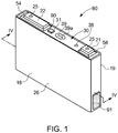
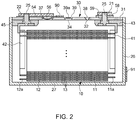
- Fig. 1 is a perspective view illustrating a battery cell according to an exemplary embodiment and Fig. 2 is a cross-sectional view taken along the IV-IV line of Fig. 1 .
- the battery cell 80 may include an electrode assembly 10, and a case 26 for accommodating the electrode assembly 10, the case 26 containing an electrolyte.
- the battery cell 80 may also include a cap assembly 30 for sealing an opening of the case 26.
- the battery cell 80 will be described as a non-limiting example of a lithium ion secondary battery configured to have a prismatic shape.
- the electrode assembly 10 may be formed as a jelly roll type electrode assembly by spirally winding a positive electrode 11 and a negative electrode 12 with a separator 13 therebetween.
- the positive electrode 11 and the negative electrode 12 may respectively include coated regions of current collectors formed of a thin metal foil, on which an active material may be coated, and may respectively include positive and negative electrode uncoated regions 11a and 12a of the current collectors on which no active material is coated.
- the coated region of the positive electrode 11 may be formed by coating a base material formed of a metal foil, such as an aluminum foil, with an active material, such as transition metal oxide or the like.
- the coated region of the negative electrode 12 may be formed by coating a base material formed of a metal foil, such as a copper or nickel foil, with an active material, such as carbon, graphite, or the like.
- the positive electrode uncoated region 11a may be formed on one lateral end of the positive electrode 11 in a longitudinal direction of the positive electrode 11, and the negative electrode uncoated region 12a may be formed on one lateral end of the negative electrode 12 in a longitudinal direction of the negative electrode 12.
- the positive electrode uncoated region 11a and the negative electrode uncoated region 12a may be on sides that are opposite to each other with respect to the coated regions.
- the separator 13 may include a plurality of separators, which may be spirally wound after the positive electrode 11, the negative electrode 12, and the separator 13 are alternately situated.
- the present invention is not limited thereto, and the electrode assembly 10 may be configured to have a structure including a plurality of sheets of the positive electrode 11, the separator 13, and the negative electrode 12 that are repeatedly stacked.
- the electrode assembly 10 may be accommodated in the case 26 together with an electrolyte solution.
- the electrolyte solution may be made of a lithium salt, such as LiPF 6 or LiBF 4 with an organic solvent, such as EC, PC, DEC, EMC, or EMC.
- the electrolyte solution may be in a liquid, solid, or gel state.
- the case 26 may be configured to have a substantially cuboidal shape, and an opening may be formed at one side thereof.
- the case 26 may be formed of a metal, such as aluminum.
- the case 26 may include a bottom surface 27 having a substantially rectangular shape, and may include a pair of first lateral walls, that are the wide side surfaces 18, 19, and a pair of second lateral walls, that are narrow side surfaces, connected vertically to end portions of the bottom surface 27, respectively, to form a space for accommodating the electrode assembly 10.
- the first lateral walls 18, 19 may face each other, and the second lateral walls may be positioned to face each other and may be connected to the first lateral walls 18, 19.
- a length of an edge at which the bottom surface 27 and a first lateral wall 18, 19 are connected to each other may be longer than that of an edge at which the bottom surface 27 and the second lateral wall are connected to each other.
- adjacent first and second lateral walls enclose an angle of about 90°.
- the cap assembly 30 may include a cap plate 31 for covering the opening of the case 26 by being bonded to the case 26, and may include a positive terminal 21 (first terminal) and a negative terminal 22 (second terminal), which are externally protruded from the cap plate 31 to be electrically connected to the positive electrode 11 and the negative electrode 12, respectively.
- the cap plate 31 may be configured to have a shape of a plate that may be extended in one direction, and that may be bonded to the opening of the case 26.
- the cap plate 31 may include an injection hole 32 and a vent hole 34 that communicate with an interior of the cap assembly 30.
- the injection hole 32 may be configured to allow the injection of the electrolyte solution, and a sealing cap 38 may be mounted thereon or therein.
- a vent member 39 including a notch 39a which may be opened due to a predetermined pressure may be mounted to or in the vent hole 34.
- the positive terminal 21 and the negative terminal 22 may be mounted to protrude upward from the cap plate 31.
- the positive terminal 21 may be electrically connected to the positive electrode 11 via a current collecting tab 41
- the negative terminal 22 may be electrically connected to the negative electrode 12 via a current collecting tab 42.
- a terminal connecting member 25 for electrically connecting the positive terminal 21 and the current collecting tab 41 may be mounted between the positive terminal 21 and the current collecting tab 41.
- the terminal connecting member 25 may be inserted into a hole formed at the positive terminal 21, such that a lower portion thereof may be welded to the current collecting tab 41.
- a gasket 59 for sealing may be mounted between the terminal connecting member 25 and the cap plate 31, while being inserted into the hole through which the terminal connecting member 25 may extend. Further, a lower insulating member 43, into which the lower portion of the terminal connecting member 25 may be inserted, may be mounted under the cap plate 31. A connecting plate 58 for electrically connecting the positive terminal 21 and the cap plate 31 may be mounted between the positive terminal 21 and the cap plate 31. The terminal connecting member 25 may be inserted into the connecting plate 58. Accordingly, the cap plate 31 and the case 26 may be positively electrified.
- a terminal connecting member 25 for electrically connecting the negative terminal 22 and the current collecting tab 42 which is similar to the terminal connecting member 25, may be installed between the negative terminal 22 and the current collecting tab 42.
- the terminal connecting member 25 may be inserted into the hole formed at the negative terminal 22, such that an upper portion and a lower portion of the terminal connecting member 25 may be, respectively, welded to the negative terminal 22 and to the current collecting tab 42.
- a gasket for sealing which is similar to the gasket 59, may be mounted between the negative terminal 22 and the cap plate 31, while being inserted into the hole through which the terminal connecting member 25 may extend.
- a lower insulating member 45 which is for insulating the negative terminal 22 and the current collecting tab 42 from the cap plate 31, may be mounted under the cap plate 31.
- An upper insulating member 54 for electrically insulating the negative terminal 22 and the cap plate 31 may be mounted between the negative terminal 22 and the cap plate 31.
- the terminal connecting member 25 may be inserted into a hole formed at the upper insulating member 54.
- the cap assembly 30 may include a short-circuiting hole 37, and a short-circuiting member 56 that may short-circuit the positive electrode 11 and the negative electrode 12 installed in the short-circuiting hole 37.
- the short-circuiting member 56 may be between the upper insulating member 54 and the cap plate 31, and the upper insulating member 54 may be configured to have a cutout that may be formed at a position corresponding to the short-circuiting member 56.
- the short-circuiting member 56 may overlap the negative terminal 22 exposed through the cutout, and may be separately located.
- the short-circuiting member 56 may be between the negative terminal 22 and the vent hole 34, and may be located closer to the negative terminal 22 than to the vent hole 34.
- the short-circuiting member 56 may include a convexly curved portion that curves toward the electrode assembly 10, and may include an edge portion may be formed at an outside of the curved portion and fixed to the cap plate 31.
- the short-circuiting member 56 may be deformed to cause a short-circuit when an internal pressure of the battery cell 80 rises. In other words, the internal pressure of the battery cell 80 may rise when a gas is generated by an unwanted reaction in the battery cell 80.
- the curved portion When the internal pressure of the battery cell 80 is increased to be higher than a level (e.g., a predetermined level), the curved portion may be deformed to be concavely curved toward an opposite direction, thereby causing the short-circuiting member 56 to contact the negative terminal 22 to cause a short-circuit.
- a level e.g., a predetermined level
- a first coating 90 is disposed on a part of the cap plate 31 and a second coating 91 is disposed on a part of a side surface of the case 26.
- the arrangement of the coatings 90, 91 is not limited thereto. Coatings may be deposited on any surface of the battery cell 80 which will be accessible for air within a housing of the battery system as will be explained in detail further below.
- the coatings 90, 91 are configured to emit at least one gaseous species when a temperature exceeds a predetermined temperature.
- the first and second coatings 90, 91 have the same composition, i.e. will emit the same gaseous species when the temperature exceeds the same predetermined temperature.
- the first and second coatings 90, 91 may also have different compositions emitting different gaseous species at for example different temperatures.
- Such coatings 90, 91 may include or consist of at least one of:
- Fig. 3 illustrates in a highly schematically way a top view on an exemplary battery system 100 according to the invention.
- the battery system 100 includes a stack of battery cells 380 being assembled and electrically interconnected to form a battery module 110.
- the battery cells 380 of the battery module 110 may be similar to the battery cell 80 described above with reference to Figs. 1 and 2 .
- Cooling plates 382 are disposed between adjacent battery cells 380.
- a coating 390 similar to the coating 90 of the embodiment of Fig. 1 is disposed on the top surface of each of the battery cells 380.
- the negative and positive terminals 321, 322 of neighboring battery cells 380 are interconnected by high current connectors 384.
- a coating 391 which allows emission of at least one gaseous species when a temperature exceeds a predetermined temperature, is disposed on the entire upper surface of the current connectors 384.
- the battery module 110 is interconnected between a first system terminal 112 and a second system terminal 114 by a plurality of high current connectors 384.
- the interconnection may further include a current sensor 116 and relays 118, 119 for connecting, respectively disconnecting the system terminals 112, 114 with the battery module 110.
- the battery system 100 further comprises a conventionally battery management system BMS 120.
- the BMS 120 may communicate to the controllers of the various electrical consumers via a suitable communication bus, e.g. a SPI or CAN interface.
- the BMS 120 may further communicate with a cell supervision circuit (CSC) of each battery module 110 (not shown).
- CSC cell supervision circuit
- the BMS 120 is provided for managing the battery system 100, such as by protecting the battery cells 380 from operating outside their safe operating area, monitoring their state, calculating secondary data, reporting that data, etc.
- the BMS communicates also with a battery disconnect unit BDU.
- the battery system 100 further includes a fan 130. Via data lines 131 the BMS 120 may regulate and supervise the activity and status of the fan 130.
- An inlet opening 132 of the fan 130 is provided on a side of the fan 130 facing the battery module 110.
- An outlet opening 133 is positioned opposite to the inlet opening 132 and opens out into a flow channel 134.
- a gas sensor 140 is positioned within the flow channel 134.
- a housing 150 is provided for accommodating the battery modules 110, the BMS 120, the fan 130, and the gas sensor 140.
- the housing may include a rigid frame structure and cover elements for hermetically closing the battery system 100.
- the housing 150 will usually be mounted to the underbody of an electric vehicle (not shown).
- a coating 392 which allows emission of at least one gaseous species, when a temperature exceeds a predetermined temperature, is disposed on an interior surface of the housing 150.
- a circulating air stream indicated by arrows 160 is formed within the housing 150.
- the air stream flows over each surface, where the coatings 390, 391, 392 are applied and the gas sensor 140 is placed within said air stream.
- a gaseous species will be emitted and transferred by the air flow towards the gas sensor 140.
- the gas sensor 140 may be selective for the gaseous species.
- Step 400 detection of the gaseous species by the gas sensor 140 causes output of a control signal CS (Step 400), followed by transmission of CS to the BMS 120 (Step 410).
- the BMS 120 may initiate in Step 420 disconnection between the first and second system terminals 112, 114 by means of the battery disconnect unit BDU, i.e. the BMS 120 is configured for transmitting a disconnect signal DS to the BDU in response to receiving the control signal CS, and the BDU is configured for disconnecting at least one of a first and second system terminal 112, 114, for example by switching relay 118 (Step 430).
- the BMS 120 determines on basis of a control signal CS of the gas sensor 140 the presence of an overheat situation in the battery system 100 and controls at least one countermeasure to said overheat situation, for example disconnection of the battery module 110.
Landscapes
- Chemical & Material Sciences (AREA)
- Chemical Kinetics & Catalysis (AREA)
- Electrochemistry (AREA)
- General Chemical & Material Sciences (AREA)
- Engineering & Computer Science (AREA)
- Manufacturing & Machinery (AREA)
- Health & Medical Sciences (AREA)
- Life Sciences & Earth Sciences (AREA)
- Physics & Mathematics (AREA)
- General Physics & Mathematics (AREA)
- Inorganic Chemistry (AREA)
- Combustion & Propulsion (AREA)
- Microelectronics & Electronic Packaging (AREA)
- Food Science & Technology (AREA)
- Medicinal Chemistry (AREA)
- Analytical Chemistry (AREA)
- Biochemistry (AREA)
- General Health & Medical Sciences (AREA)
- Immunology (AREA)
- Pathology (AREA)
- Secondary Cells (AREA)
- Battery Mounting, Suspending (AREA)
Claims (11)
- Ein Batteriesystem (100) für ein Fahrzeug, aufweisend:- ein oder mehrere Batteriemodule (110), die jeweils eine Vielzahl von Sekundärbatteriezellen (80, 380) aufweisen;- zumindest einen Gassensor (140); und- ein Gehäuse (150) zum Aufnehmen des einen oder der mehreren Batteriemodule (110) und des zumindest einen Gassensors (140);wobei zumindest Teile der Außenfläche der Batteriemodule (110) und/oder zumindest Teile der Innenfläche des Gehäuses (150) mit einer Beschichtung (90, 91, 390, 391, 392) bedeckt sind, die konfiguriert ist, um zumindest eine Gasart zu emittieren, wenn eine Temperatur eine vorbestimmte Temperatur überschreitet, und wobei der Gassensor (140) konfiguriert ist, um die zumindest eine Gasart zu erkennen.
- Das Batteriesystem nach Anspruch 1, wobei die Beschichtung (90, 91, 390, 391, 392) zumindest eines von Folgendem aufweist oder daraus besteht:(i) ein reaktives System, das die zumindest eine Gasart durch eine chemische Reaktion bei der vorbestimmten Temperatur erzeugt;(ii) eine Verbindung, die einen Siedepunkt oder einen Sublimationspunkt bei der vorbestimmten Temperatur aufweist, wobei die Gasphase der Verbindung die Gasart darstellt; und(iii) ein Matrixsystem, das die Gasart aufweist und konfiguriert ist, um die Gasart bei der vorbestimmten Temperatur zu emittieren.
- Das Batteriesystem nach Anspruch 1, wobei die Beschichtung (90, 91, 390, 391, 392) auf zumindest einem von Folgendem bereitgestellt wird:- einer Außenfläche einer Batteriezelle (80, 380);- einer elektrischen Verdrahtung des Batteriesystems (100); und- eines Kühlelements für Batteriezellen (80) und Batteriemodule (110).
- Das Batteriesystem nach Anspruch 3, wobei die elektrische Verdrahtung Stromverbinder (384) aufweist und wobei die Beschichtung (391) auf den Stromverbindern (384) angeordnet ist.
- Das Batteriesystem nach Anspruch 1, ferner aufweisend Mittel zum Ausbilden eines zirkulierenden Luftstroms im Gehäuse (150), wobei der Luftstrom über die Oberflächen strömt, wo die Beschichtung (390, 391, 392) aufgebracht ist, und der zumindest eine Gassensor (140) im Luftstrom positioniert ist.
- Das Batteriesystem nach Anspruch 5, wobei die Mittel zum Ausbilden des Luftstroms einen Ventilator (130) aufweisen und der zumindest eine Gassensor (140) im Luftstrom, der aus dem Ventilator (130) ausströmt, positioniert ist.
- Das Batteriesystem nach einem der vorhergehenden Ansprüche, ferner aufweisend ein Batteriemanagementsystem BMS (120), das mit dem zumindest einen Gassensor (140) verbunden ist, wobei der zumindest eine Gassensor (140) konfiguriert ist, um in Reaktion auf das Erkennen der zumindest einen Gasart ein Steuersignal CS zum BMS (120) zu übertragen.
- Das Batteriesystem nach Anspruch 7, ferner aufweisend eine Batterietrenneinheit BDU, die zwischen zumindest einen eines ersten und zweiten Systemanschlusses (112, 114) und das zumindest eine Batteriemodul (110) geschaltet ist, wobei das BMS (120) konfiguriert ist, um in Reaktion auf das Empfangen des Steuersignals CS ein Trennsignal DS zur BDU zu übertragen, und wobei die BDU konfiguriert ist, um in Reaktion auf das Trennsignal DS zumindest einen eines ersten und zweiten Systemanschlusses (112, 114) des zumindest einen Batteriemoduls (110) zu trennen.
- Ein Fahrzeug, aufweisend ein Batteriesystem (100) nach einem der vorhergehenden Ansprüche.
- Ein Verfahren zur Erkennung einer Überhitzungssituation eines Batteriesystems (100), das die folgenden Schritte aufweist:a) Bereitstellen eines Batteriesystems, aufweisend:- ein oder mehrere Batteriemodule (110), die jeweils eine Vielzahl von Sekundärbatteriezellen (80, 380) aufweisen;- zumindest einen Gassensor (140); und- ein Gehäuse (150) zum Aufnehmen des einen oder der mehreren Batteriemodule (110) und des zumindest einen Gassensors (140); und- ein Batteriemanagementsystem BMS (120),wobei zumindest Teile der Außenfläche der Batteriemodule (110) und/oder zumindest Teile der Innenfläche des Gehäuses (150) mit einer Beschichtung (90, 91, 390, 391, 392) bedeckt sind, die konfiguriert ist, um zumindest eine Gasart zu emittieren, wenn eine Temperatur eine vorbestimmte Temperatur überschreitet, und wobei der Gassensor (140) konfiguriert ist, um die zumindest eine Gasart zu erkennen;b) Erkennen der zumindest einen Gasart mit dem Gassensor (140); undc) Übertragen zumindest eines Steuersignals CS vom Gassensor (140) zum BMS (120) in Reaktion auf das Erkennen der zumindest einen Gasart.
- Das Verfahren nach Anspruch 10, ferner aufweisend die folgenden Schritte:d) Bestimmen des Vorliegens einer Überhitzungssituation im Batteriesystem (100); unde) Steuern zumindest einer Gegenmaßnahme gegen die Überhitzungssituation.
Priority Applications (5)
| Application Number | Priority Date | Filing Date | Title |
|---|---|---|---|
| PL18198757T PL3633754T3 (pl) | 2018-10-05 | 2018-10-05 | Układ akumulatora dla pojazdu i sposób wykrywania sytuacji przegrzania układu akumulatora |
| HUE18198757A HUE053646T2 (hu) | 2018-10-05 | 2018-10-05 | Akkumulátor rendszer egy jármûhöz, és eljárás az akkumulátor rendszer túlmelegedési szituációjának kimutatására |
| EP18198757.9A EP3633754B1 (de) | 2018-10-05 | 2018-10-05 | Batteriesystem für ein fahrzeug und verfahren zur erkennung einer überhitzungssituation des batteriesystems |
| KR1020190114258A KR20200040190A (ko) | 2018-10-05 | 2019-09-17 | 차량용 전지 시스템 및 전지 시스템의 과열 상황 검출 방법 |
| US16/589,509 US10992013B2 (en) | 2018-10-05 | 2019-10-01 | Battery system for a vehicle and method for detecting an overheat situation of the battery system |
Applications Claiming Priority (1)
| Application Number | Priority Date | Filing Date | Title |
|---|---|---|---|
| EP18198757.9A EP3633754B1 (de) | 2018-10-05 | 2018-10-05 | Batteriesystem für ein fahrzeug und verfahren zur erkennung einer überhitzungssituation des batteriesystems |
Publications (2)
| Publication Number | Publication Date |
|---|---|
| EP3633754A1 EP3633754A1 (de) | 2020-04-08 |
| EP3633754B1 true EP3633754B1 (de) | 2021-01-27 |
Family
ID=63787762
Family Applications (1)
| Application Number | Title | Priority Date | Filing Date |
|---|---|---|---|
| EP18198757.9A Active EP3633754B1 (de) | 2018-10-05 | 2018-10-05 | Batteriesystem für ein fahrzeug und verfahren zur erkennung einer überhitzungssituation des batteriesystems |
Country Status (4)
| Country | Link |
|---|---|
| EP (1) | EP3633754B1 (de) |
| KR (1) | KR20200040190A (de) |
| HU (1) | HUE053646T2 (de) |
| PL (1) | PL3633754T3 (de) |
Families Citing this family (7)
| Publication number | Priority date | Publication date | Assignee | Title |
|---|---|---|---|---|
| WO2022045589A1 (ko) * | 2020-08-31 | 2022-03-03 | 주식회사 엘지에너지솔루션 | 손상된 전지 셀의 검출이 가능한 전지 시스템 및 전지 모듈 평가 방법 |
| KR102684679B1 (ko) * | 2020-08-31 | 2024-07-15 | 주식회사 엘지에너지솔루션 | 손상된 전지 셀의 검출이 가능한 전지 시스템 및 전지 모듈 평가 방법 |
| FR3115933A1 (fr) * | 2020-10-29 | 2022-05-06 | Commissariat à l'Energie Atomique et aux Energies Alternatives | Système d'alimentation électrique |
| EP4216334A1 (de) * | 2022-01-20 | 2023-07-26 | Abb Schweiz Ag | Batteriezelle, batteriemodul, batteriepack, batterieverwaltungssystem und verfahren zur bestimmung eines wertes mindestens eines verschleissparameters einer batteriezelle |
| EP4366031A1 (de) * | 2022-11-07 | 2024-05-08 | Honeywell International Inc. | System und verfahren zur früherkennung von thermischem durchgehen in lithium-ionen-batterien |
| CN118472441A (zh) * | 2023-02-08 | 2024-08-09 | 宁德时代新能源科技股份有限公司 | 电池单体、电池及用电装置 |
| CN116840423B (zh) * | 2023-08-29 | 2024-02-20 | 宁德时代新能源科技股份有限公司 | 储能装置及其气体浓度的检测方法 |
Family Cites Families (2)
| Publication number | Priority date | Publication date | Assignee | Title |
|---|---|---|---|---|
| DE102012215883A1 (de) * | 2012-09-07 | 2014-03-13 | Robert Bosch Gmbh | Energiespeicher mit Dichtigkeitsüberwachung |
| KR20230047195A (ko) * | 2014-11-25 | 2023-04-06 | 아메리칸 리튬 에너지 코포레이션 | 내부 전류 제한기 및 차단기를 갖는 재충전가능 배터리 |
-
2018
- 2018-10-05 PL PL18198757T patent/PL3633754T3/pl unknown
- 2018-10-05 HU HUE18198757A patent/HUE053646T2/hu unknown
- 2018-10-05 EP EP18198757.9A patent/EP3633754B1/de active Active
-
2019
- 2019-09-17 KR KR1020190114258A patent/KR20200040190A/ko unknown
Non-Patent Citations (1)
| Title |
|---|
| None * |
Also Published As
| Publication number | Publication date |
|---|---|
| EP3633754A1 (de) | 2020-04-08 |
| HUE053646T2 (hu) | 2021-07-28 |
| PL3633754T3 (pl) | 2021-08-30 |
| KR20200040190A (ko) | 2020-04-17 |
Similar Documents
| Publication | Publication Date | Title |
|---|---|---|
| US10992013B2 (en) | Battery system for a vehicle and method for detecting an overheat situation of the battery system | |
| EP3633754B1 (de) | Batteriesystem für ein fahrzeug und verfahren zur erkennung einer überhitzungssituation des batteriesystems | |
| US10476068B2 (en) | Battery module including probe for detecting expansion of battery cell | |
| CN109906524B (zh) | 电池系统 | |
| US20190379030A1 (en) | Battery system configured to detect abnormal battery system conditions and method of the same | |
| WO2012157855A1 (ko) | 안전성이 향상된 전지팩 | |
| EP3506383B1 (de) | Batteriemodul | |
| KR20190139134A (ko) | 전지 시스템 및 이의 비정상 상태 검출 방법 | |
| US20220115717A1 (en) | Apparatus for detecting thermal runaway of battery for electric vehicle | |
| US11764409B2 (en) | Battery system, method for leakage detection inside the battery system, and vehicle including the battery system | |
| KR102586103B1 (ko) | 배터리 시스템, 배터리 시스템 내부 누출 검출 방법, 및 배터리 시스템을 포함하는 차량 | |
| KR20150045241A (ko) | 단선장치를 구비하는 배터리 셀, 그리고 이를 포함하는 배터리 모듈 및 배터리 팩 | |
| US20230187773A1 (en) | Battery system with a cover element forming a venting channel | |
| JP2020042968A (ja) | 蓄電装置モジュール | |
| KR20190001408A (ko) | 배터리 모듈과 이를 포함하는 배터리 팩 및 자동차 | |
| EP4220820A1 (de) | Batteriesystem mit aktiver kühlung des belüftungskanals | |
| US11900785B2 (en) | Thermal protection of connector | |
| KR20230034174A (ko) | 전지 시스템, 이의 비정상 작동 상태 감지 방법 및 전기 차량 | |
| CN114919457A (zh) | 用于车辆的动力电池系统和热评估方法 | |
| EP4199210A1 (de) | Batteriesystem mit einem abdeckelement, das einen entlüftungskanal bildet | |
| CN113471641B (zh) | 电池系统和包括至少一个电池系统的车辆 | |
| EP3890054B1 (de) | Batteriesystem und fahrzeug mit mindestens einem batteriesystem | |
| EP4199211A1 (de) | Batteriezelle und batteriesystem | |
| EP4266450A1 (de) | Batteriesystem mit kühlerstrahlen | |
| US20230344038A1 (en) | Battery system with cooler beams |
Legal Events
| Date | Code | Title | Description |
|---|---|---|---|
| PUAI | Public reference made under article 153(3) epc to a published international application that has entered the european phase |
Free format text: ORIGINAL CODE: 0009012 |
|
| STAA | Information on the status of an ep patent application or granted ep patent |
Free format text: STATUS: REQUEST FOR EXAMINATION WAS MADE |
|
| 17P | Request for examination filed |
Effective date: 20191106 |
|
| AK | Designated contracting states |
Kind code of ref document: A1 Designated state(s): AL AT BE BG CH CY CZ DE DK EE ES FI FR GB GR HR HU IE IS IT LI LT LU LV MC MK MT NL NO PL PT RO RS SE SI SK SM TR |
|
| AX | Request for extension of the european patent |
Extension state: BA ME |
|
| GRAP | Despatch of communication of intention to grant a patent |
Free format text: ORIGINAL CODE: EPIDOSNIGR1 |
|
| STAA | Information on the status of an ep patent application or granted ep patent |
Free format text: STATUS: GRANT OF PATENT IS INTENDED |
|
| INTG | Intention to grant announced |
Effective date: 20200909 |
|
| RAP1 | Party data changed (applicant data changed or rights of an application transferred) |
Owner name: SAMSUNG SDI CO., LTD. |
|
| GRAS | Grant fee paid |
Free format text: ORIGINAL CODE: EPIDOSNIGR3 |
|
| GRAA | (expected) grant |
Free format text: ORIGINAL CODE: 0009210 |
|
| STAA | Information on the status of an ep patent application or granted ep patent |
Free format text: STATUS: THE PATENT HAS BEEN GRANTED |
|
| AK | Designated contracting states |
Kind code of ref document: B1 Designated state(s): AL AT BE BG CH CY CZ DE DK EE ES FI FR GB GR HR HU IE IS IT LI LT LU LV MC MK MT NL NO PL PT RO RS SE SI SK SM TR |
|
| REG | Reference to a national code |
Ref country code: GB Ref legal event code: FG4D |
|
| REG | Reference to a national code |
Ref country code: CH Ref legal event code: EP |
|
| REG | Reference to a national code |
Ref country code: AT Ref legal event code: REF Ref document number: 1359157 Country of ref document: AT Kind code of ref document: T Effective date: 20210215 |
|
| REG | Reference to a national code |
Ref country code: IE Ref legal event code: FG4D |
|
| REG | Reference to a national code |
Ref country code: DE Ref legal event code: R096 Ref document number: 602018012233 Country of ref document: DE |
|
| REG | Reference to a national code |
Ref country code: NL Ref legal event code: MP Effective date: 20210127 |
|
| REG | Reference to a national code |
Ref country code: LT Ref legal event code: MG9D |
|
| REG | Reference to a national code |
Ref country code: AT Ref legal event code: MK05 Ref document number: 1359157 Country of ref document: AT Kind code of ref document: T Effective date: 20210127 |
|
| REG | Reference to a national code |
Ref country code: HU Ref legal event code: AG4A Ref document number: E053646 Country of ref document: HU |
|
| PG25 | Lapsed in a contracting state [announced via postgrant information from national office to epo] |
Ref country code: PT Free format text: LAPSE BECAUSE OF FAILURE TO SUBMIT A TRANSLATION OF THE DESCRIPTION OR TO PAY THE FEE WITHIN THE PRESCRIBED TIME-LIMIT Effective date: 20210527 Ref country code: NO Free format text: LAPSE BECAUSE OF FAILURE TO SUBMIT A TRANSLATION OF THE DESCRIPTION OR TO PAY THE FEE WITHIN THE PRESCRIBED TIME-LIMIT Effective date: 20210427 Ref country code: LT Free format text: LAPSE BECAUSE OF FAILURE TO SUBMIT A TRANSLATION OF THE DESCRIPTION OR TO PAY THE FEE WITHIN THE PRESCRIBED TIME-LIMIT Effective date: 20210127 Ref country code: HR Free format text: LAPSE BECAUSE OF FAILURE TO SUBMIT A TRANSLATION OF THE DESCRIPTION OR TO PAY THE FEE WITHIN THE PRESCRIBED TIME-LIMIT Effective date: 20210127 Ref country code: FI Free format text: LAPSE BECAUSE OF FAILURE TO SUBMIT A TRANSLATION OF THE DESCRIPTION OR TO PAY THE FEE WITHIN THE PRESCRIBED TIME-LIMIT Effective date: 20210127 Ref country code: GR Free format text: LAPSE BECAUSE OF FAILURE TO SUBMIT A TRANSLATION OF THE DESCRIPTION OR TO PAY THE FEE WITHIN THE PRESCRIBED TIME-LIMIT Effective date: 20210428 Ref country code: BG Free format text: LAPSE BECAUSE OF FAILURE TO SUBMIT A TRANSLATION OF THE DESCRIPTION OR TO PAY THE FEE WITHIN THE PRESCRIBED TIME-LIMIT Effective date: 20210427 |
|
| PG25 | Lapsed in a contracting state [announced via postgrant information from national office to epo] |
Ref country code: AT Free format text: LAPSE BECAUSE OF FAILURE TO SUBMIT A TRANSLATION OF THE DESCRIPTION OR TO PAY THE FEE WITHIN THE PRESCRIBED TIME-LIMIT Effective date: 20210127 Ref country code: LV Free format text: LAPSE BECAUSE OF FAILURE TO SUBMIT A TRANSLATION OF THE DESCRIPTION OR TO PAY THE FEE WITHIN THE PRESCRIBED TIME-LIMIT Effective date: 20210127 Ref country code: RS Free format text: LAPSE BECAUSE OF FAILURE TO SUBMIT A TRANSLATION OF THE DESCRIPTION OR TO PAY THE FEE WITHIN THE PRESCRIBED TIME-LIMIT Effective date: 20210127 Ref country code: SE Free format text: LAPSE BECAUSE OF FAILURE TO SUBMIT A TRANSLATION OF THE DESCRIPTION OR TO PAY THE FEE WITHIN THE PRESCRIBED TIME-LIMIT Effective date: 20210127 |
|
| PG25 | Lapsed in a contracting state [announced via postgrant information from national office to epo] |
Ref country code: IS Free format text: LAPSE BECAUSE OF FAILURE TO SUBMIT A TRANSLATION OF THE DESCRIPTION OR TO PAY THE FEE WITHIN THE PRESCRIBED TIME-LIMIT Effective date: 20210527 |
|
| REG | Reference to a national code |
Ref country code: DE Ref legal event code: R097 Ref document number: 602018012233 Country of ref document: DE |
|
| PG25 | Lapsed in a contracting state [announced via postgrant information from national office to epo] |
Ref country code: SM Free format text: LAPSE BECAUSE OF FAILURE TO SUBMIT A TRANSLATION OF THE DESCRIPTION OR TO PAY THE FEE WITHIN THE PRESCRIBED TIME-LIMIT Effective date: 20210127 Ref country code: EE Free format text: LAPSE BECAUSE OF FAILURE TO SUBMIT A TRANSLATION OF THE DESCRIPTION OR TO PAY THE FEE WITHIN THE PRESCRIBED TIME-LIMIT Effective date: 20210127 Ref country code: CZ Free format text: LAPSE BECAUSE OF FAILURE TO SUBMIT A TRANSLATION OF THE DESCRIPTION OR TO PAY THE FEE WITHIN THE PRESCRIBED TIME-LIMIT Effective date: 20210127 |
|
| PG25 | Lapsed in a contracting state [announced via postgrant information from national office to epo] |
Ref country code: DK Free format text: LAPSE BECAUSE OF FAILURE TO SUBMIT A TRANSLATION OF THE DESCRIPTION OR TO PAY THE FEE WITHIN THE PRESCRIBED TIME-LIMIT Effective date: 20210127 Ref country code: RO Free format text: LAPSE BECAUSE OF FAILURE TO SUBMIT A TRANSLATION OF THE DESCRIPTION OR TO PAY THE FEE WITHIN THE PRESCRIBED TIME-LIMIT Effective date: 20210127 Ref country code: SK Free format text: LAPSE BECAUSE OF FAILURE TO SUBMIT A TRANSLATION OF THE DESCRIPTION OR TO PAY THE FEE WITHIN THE PRESCRIBED TIME-LIMIT Effective date: 20210127 |
|
| PLBE | No opposition filed within time limit |
Free format text: ORIGINAL CODE: 0009261 |
|
| STAA | Information on the status of an ep patent application or granted ep patent |
Free format text: STATUS: NO OPPOSITION FILED WITHIN TIME LIMIT |
|
| 26N | No opposition filed |
Effective date: 20211028 |
|
| PG25 | Lapsed in a contracting state [announced via postgrant information from national office to epo] |
Ref country code: AL Free format text: LAPSE BECAUSE OF FAILURE TO SUBMIT A TRANSLATION OF THE DESCRIPTION OR TO PAY THE FEE WITHIN THE PRESCRIBED TIME-LIMIT Effective date: 20210127 Ref country code: ES Free format text: LAPSE BECAUSE OF FAILURE TO SUBMIT A TRANSLATION OF THE DESCRIPTION OR TO PAY THE FEE WITHIN THE PRESCRIBED TIME-LIMIT Effective date: 20210127 |
|
| PG25 | Lapsed in a contracting state [announced via postgrant information from national office to epo] |
Ref country code: SI Free format text: LAPSE BECAUSE OF FAILURE TO SUBMIT A TRANSLATION OF THE DESCRIPTION OR TO PAY THE FEE WITHIN THE PRESCRIBED TIME-LIMIT Effective date: 20210127 |
|
| PG25 | Lapsed in a contracting state [announced via postgrant information from national office to epo] |
Ref country code: IT Free format text: LAPSE BECAUSE OF FAILURE TO SUBMIT A TRANSLATION OF THE DESCRIPTION OR TO PAY THE FEE WITHIN THE PRESCRIBED TIME-LIMIT Effective date: 20210127 |
|
| REG | Reference to a national code |
Ref country code: CH Ref legal event code: PL |
|
| PG25 | Lapsed in a contracting state [announced via postgrant information from national office to epo] |
Ref country code: IS Free format text: LAPSE BECAUSE OF FAILURE TO SUBMIT A TRANSLATION OF THE DESCRIPTION OR TO PAY THE FEE WITHIN THE PRESCRIBED TIME-LIMIT Effective date: 20210527 |
|
| REG | Reference to a national code |
Ref country code: BE Ref legal event code: MM Effective date: 20211031 |
|
| PG25 | Lapsed in a contracting state [announced via postgrant information from national office to epo] |
Ref country code: MC Free format text: LAPSE BECAUSE OF FAILURE TO SUBMIT A TRANSLATION OF THE DESCRIPTION OR TO PAY THE FEE WITHIN THE PRESCRIBED TIME-LIMIT Effective date: 20210127 |
|
| PG25 | Lapsed in a contracting state [announced via postgrant information from national office to epo] |
Ref country code: LU Free format text: LAPSE BECAUSE OF NON-PAYMENT OF DUE FEES Effective date: 20211005 Ref country code: BE Free format text: LAPSE BECAUSE OF NON-PAYMENT OF DUE FEES Effective date: 20211031 |
|
| PG25 | Lapsed in a contracting state [announced via postgrant information from national office to epo] |
Ref country code: LI Free format text: LAPSE BECAUSE OF NON-PAYMENT OF DUE FEES Effective date: 20211031 Ref country code: CH Free format text: LAPSE BECAUSE OF NON-PAYMENT OF DUE FEES Effective date: 20211031 |
|
| PG25 | Lapsed in a contracting state [announced via postgrant information from national office to epo] |
Ref country code: IE Free format text: LAPSE BECAUSE OF NON-PAYMENT OF DUE FEES Effective date: 20211005 |
|
| PG25 | Lapsed in a contracting state [announced via postgrant information from national office to epo] |
Ref country code: NL Free format text: LAPSE BECAUSE OF NON-PAYMENT OF DUE FEES Effective date: 20210127 Ref country code: CY Free format text: LAPSE BECAUSE OF FAILURE TO SUBMIT A TRANSLATION OF THE DESCRIPTION OR TO PAY THE FEE WITHIN THE PRESCRIBED TIME-LIMIT Effective date: 20210127 |
|
| P01 | Opt-out of the competence of the unified patent court (upc) registered |
Effective date: 20230528 |
|
| PGFP | Annual fee paid to national office [announced via postgrant information from national office to epo] |
Ref country code: PL Payment date: 20230929 Year of fee payment: 6 Ref country code: FR Payment date: 20230929 Year of fee payment: 6 |
|
| PGFP | Annual fee paid to national office [announced via postgrant information from national office to epo] |
Ref country code: GB Payment date: 20231006 Year of fee payment: 6 |
|
| PGFP | Annual fee paid to national office [announced via postgrant information from national office to epo] |
Ref country code: HU Payment date: 20231019 Year of fee payment: 6 Ref country code: DE Payment date: 20230929 Year of fee payment: 6 |
|
| PG25 | Lapsed in a contracting state [announced via postgrant information from national office to epo] |
Ref country code: MK Free format text: LAPSE BECAUSE OF FAILURE TO SUBMIT A TRANSLATION OF THE DESCRIPTION OR TO PAY THE FEE WITHIN THE PRESCRIBED TIME-LIMIT Effective date: 20210127 |