EP3633426A1 - Optical fiber, method for manufacturing optical fiber, and optical fiber base material - Google Patents
Optical fiber, method for manufacturing optical fiber, and optical fiber base material Download PDFInfo
- Publication number
- EP3633426A1 EP3633426A1 EP18810607.4A EP18810607A EP3633426A1 EP 3633426 A1 EP3633426 A1 EP 3633426A1 EP 18810607 A EP18810607 A EP 18810607A EP 3633426 A1 EP3633426 A1 EP 3633426A1
- Authority
- EP
- European Patent Office
- Prior art keywords
- optical fiber
- cladding layer
- transmission loss
- concentration
- core
- Prior art date
- Legal status (The legal status is an assumption and is not a legal conclusion. Google has not performed a legal analysis and makes no representation as to the accuracy of the status listed.)
- Granted
Links
Images
Classifications
-
- C—CHEMISTRY; METALLURGY
- C03—GLASS; MINERAL OR SLAG WOOL
- C03B—MANUFACTURE, SHAPING, OR SUPPLEMENTARY PROCESSES
- C03B37/00—Manufacture or treatment of flakes, fibres, or filaments from softened glass, minerals, or slags
- C03B37/01—Manufacture of glass fibres or filaments
- C03B37/012—Manufacture of preforms for drawing fibres or filaments
- C03B37/014—Manufacture of preforms for drawing fibres or filaments made entirely or partially by chemical means, e.g. vapour phase deposition of bulk porous glass either by outside vapour deposition [OVD], or by outside vapour phase oxidation [OVPO] or by vapour axial deposition [VAD]
- C03B37/01446—Thermal after-treatment of preforms, e.g. dehydrating, consolidating, sintering
-
- C—CHEMISTRY; METALLURGY
- C03—GLASS; MINERAL OR SLAG WOOL
- C03B—MANUFACTURE, SHAPING, OR SUPPLEMENTARY PROCESSES
- C03B37/00—Manufacture or treatment of flakes, fibres, or filaments from softened glass, minerals, or slags
- C03B37/01—Manufacture of glass fibres or filaments
- C03B37/012—Manufacture of preforms for drawing fibres or filaments
- C03B37/014—Manufacture of preforms for drawing fibres or filaments made entirely or partially by chemical means, e.g. vapour phase deposition of bulk porous glass either by outside vapour deposition [OVD], or by outside vapour phase oxidation [OVPO] or by vapour axial deposition [VAD]
- C03B37/018—Manufacture of preforms for drawing fibres or filaments made entirely or partially by chemical means, e.g. vapour phase deposition of bulk porous glass either by outside vapour deposition [OVD], or by outside vapour phase oxidation [OVPO] or by vapour axial deposition [VAD] by glass deposition on a glass substrate, e.g. by inside-, modified-, plasma- or plasma modified- chemical vapour deposition [ICVD, MCVD, PCVD, PMCVD], i.e. by thin layer coating on the inside or outside of a glass tube or on a glass rod
- C03B37/01853—Thermal after-treatment of preforms, e.g. dehydrating, consolidating, sintering
-
- G—PHYSICS
- G02—OPTICS
- G02B—OPTICAL ELEMENTS, SYSTEMS OR APPARATUS
- G02B6/00—Light guides; Structural details of arrangements comprising light guides and other optical elements, e.g. couplings
- G02B6/02—Optical fibres with cladding with or without a coating
-
- G—PHYSICS
- G02—OPTICS
- G02B—OPTICAL ELEMENTS, SYSTEMS OR APPARATUS
- G02B6/00—Light guides; Structural details of arrangements comprising light guides and other optical elements, e.g. couplings
- G02B6/02—Optical fibres with cladding with or without a coating
- G02B6/036—Optical fibres with cladding with or without a coating core or cladding comprising multiple layers
- G02B6/03616—Optical fibres characterised both by the number of different refractive index layers around the central core segment, i.e. around the innermost high index core layer, and their relative refractive index difference
- G02B6/03622—Optical fibres characterised both by the number of different refractive index layers around the central core segment, i.e. around the innermost high index core layer, and their relative refractive index difference having 2 layers only
-
- G—PHYSICS
- G02—OPTICS
- G02B—OPTICAL ELEMENTS, SYSTEMS OR APPARATUS
- G02B6/00—Light guides; Structural details of arrangements comprising light guides and other optical elements, e.g. couplings
- G02B6/02—Optical fibres with cladding with or without a coating
- G02B6/036—Optical fibres with cladding with or without a coating core or cladding comprising multiple layers
- G02B6/03694—Multiple layers differing in properties other than the refractive index, e.g. attenuation, diffusion, stress properties
-
- C—CHEMISTRY; METALLURGY
- C03—GLASS; MINERAL OR SLAG WOOL
- C03B—MANUFACTURE, SHAPING, OR SUPPLEMENTARY PROCESSES
- C03B2201/00—Type of glass produced
- C03B2201/06—Doped silica-based glasses
- C03B2201/07—Impurity concentration specified
- C03B2201/075—Hydroxyl ion (OH)
-
- C—CHEMISTRY; METALLURGY
- C03—GLASS; MINERAL OR SLAG WOOL
- C03B—MANUFACTURE, SHAPING, OR SUPPLEMENTARY PROCESSES
- C03B2201/00—Type of glass produced
- C03B2201/06—Doped silica-based glasses
- C03B2201/08—Doped silica-based glasses doped with boron or fluorine or other refractive index decreasing dopant
- C03B2201/12—Doped silica-based glasses doped with boron or fluorine or other refractive index decreasing dopant doped with fluorine
-
- C—CHEMISTRY; METALLURGY
- C03—GLASS; MINERAL OR SLAG WOOL
- C03B—MANUFACTURE, SHAPING, OR SUPPLEMENTARY PROCESSES
- C03B2201/00—Type of glass produced
- C03B2201/06—Doped silica-based glasses
- C03B2201/20—Doped silica-based glasses doped with non-metals other than boron or fluorine
-
- G—PHYSICS
- G02—OPTICS
- G02B—OPTICAL ELEMENTS, SYSTEMS OR APPARATUS
- G02B6/00—Light guides; Structural details of arrangements comprising light guides and other optical elements, e.g. couplings
- G02B6/02—Optical fibres with cladding with or without a coating
- G02B6/036—Optical fibres with cladding with or without a coating core or cladding comprising multiple layers
- G02B6/03616—Optical fibres characterised both by the number of different refractive index layers around the central core segment, i.e. around the innermost high index core layer, and their relative refractive index difference
- G02B6/03622—Optical fibres characterised both by the number of different refractive index layers around the central core segment, i.e. around the innermost high index core layer, and their relative refractive index difference having 2 layers only
- G02B6/03627—Optical fibres characterised both by the number of different refractive index layers around the central core segment, i.e. around the innermost high index core layer, and their relative refractive index difference having 2 layers only arranged - +
Definitions
- the present invention relates to an optical fiber, a method for manufacturing an optical fiber, and an optical fiber preform.
- an optical fiber used in an optical communication system in order to increase the possible transmission distance of an optical signal, it is required to improve an optical signal to noise ratio (OSNR).
- OSNR optical signal to noise ratio
- a Ge-doped core fiber in which a core is doped with germanium dioxide is generally widely used.
- Rayleigh scattering can be further limited as compared to the Ge-doped core fiber, and thus a further reduction in transmission loss is expected.
- Patent Document 1 discloses a method of dehydrating a core by causing halogen gas such as chlorine gas (Cl 2 ) to flow and to react with hydrogen gas (H 2 ) when a soot deposited using a vapor-phase axial deposition method (VAD method) is sintered. In this method, the dehydration is performed during the formation of a glass preform. Therefore, initial transmission loss of an optical fiber can be reduced.
- halogen gas such as chlorine gas (Cl 2 )
- Patent Document 2 discloses a method of dehydrating a cladding layer using SiCl 4 after adding fluorine (F) to the cladding layer.
- F fluorine
- CI chlorine
- Patent Document 2 As compared to Cl, F tends to further increase Rayleigh scattering due to concentration fluctuation thereof, and the presence of an excess amount of F in the cladding layer in the vicinity of the core leads to an increase in the transmission loss of the optical fiber.
- the method disclosed in Patent Document 2 also has room for improvement.
- the present invention has been made in consideration of the above-described circumstances, and an object thereof is to provide an optical fiber in which a phenomenon of increasing transmission loss during exposure to hydrogen is limited.
- an optical fiber including: a core; and a cladding layer that is provided on an outer circumference of the core, in which a Cl concentration in the cladding layer is 0.029 wt% to 0.098 wt%.
- a method for manufacturing an optical fiber including a core and a cladding layer that is provided on an outer circumference of the core, the method including dehydrating the cladding layer with Cl-containing gas such that a Cl concentration in the cladding layer is 0.029 wt% to 0.098 wt%.
- an optical fiber preform for manufacturing an optical fiber including a core and a cladding layer that is provided on an outer circumference of the core, in which a Cl concentration in a soot that forms the cladding layer is 0.029 wt% to 0.098 wt%.
- an optical fiber in which a phenomenon of increasing transmission loss during exposure to hydrogen is limited can be provided.
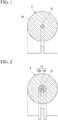
- the optical fiber according to the embodiment is an optical fiber 1 having, for example, a stepwise refractive index profile shown in FIG. 1 or a W-shaped refractive index profile shown in FIG. 2 .
- the refractive index profile of the optical fiber 1 is not limited to the example shown in FIG. 1 or 2 .
- the optical fiber 1 includes a core 11 and a cladding layer 12 that is formed on an outer circumference of the core 11.
- the optical fiber 1 is a silica core fiber in which the core 11 is formed of silicon dioxide (SiO 2 ) and additives such as germanium are not added.
- the optical fiber 1 shown in FIG. 1 includes the cladding layer 12 having a single-layer structure, and the optical fiber 1 shown in FIG. 2 includes the cladding layer 12 having a multiple-layer structure including an inner cladding layer 12a and an outer cladding layer 12b.
- An optical fiber preform for manufacturing the optical fiber 1 according to the embodiment can be manufactured as follows.
- a soot (hereinafter, referred to as "core soot") that forms the core 11 of SiO 2 is formed using a VAD method.
- F may be added to the material using fluorine (F) -containing gas which includes fluorine, the F-containing gas such as SiF 4 , C 2 F 6 , SF 6 , or CF 4 .
- the material that forms the core 11 may include alkali metal such as sodium (Na) or potassium (K).
- Cl-containing gas which includes chlorine
- the Cl-containing gas such as SOCl 2 or Cl 2
- F or the alkali metal for adjusting the viscosity may be added to the core soot.
- the dehydrated core soot is heated in a helium (He) atmosphere to be vitrified such that core glass is obtained. It is preferable that the dehydration is performed such that the core glass includes about 0.2 to 2.0 wt% of Cl.
- the shape of the refractive index profile of the core may become higher or lower from the outer circumference toward the inside, may be stepwise, or may be flat (uniform).
- a soot (hereinafter, referred to as "cladding soot") that forms the cladding layer 12 is formed on the outer circumference of the core glass using an outside vapor-deposition method.
- “deposition” of depositing the cladding soot on the outer circumference of the core glass is performed.
- the deposition is performed in a state where the surface of the core glass is etched with etching gas such as SF 6 or C 2 F 6 to remove remaining water.
- the core glass and the cladding soot may be drawn in order to obtain an outer diameter in which the soot can be easily vapor-deposited.
- the cladding layer 12 may be vapor-deposited multiple times so as to obtain a desired outer diameter.
- Cl-containing gas such as SOCl 2 or Cl 2 and F-containing gas such as SiF 4 are mixed with each other, and this mixed gas is diffused and is caused to react in the cladding soot.
- the dehydration treatment and the F addition treatment of the cladding soot can be simultaneously performed.
- the cladding soot on which the dehydration treatment and the F addition treatment are performed is heated in a F-containing gas atmosphere to be vitrified such that the cladding layer 12 is formed.
- the cladding layer 12 is dehydrated such that an average Cl concentration distribution in a cross-section is 0.029 wt% or higher.
- the cladding layer 12 is dehydrated such that an average Cl concentration profile in a cross-section is 0.098 wt% or lower.
- the Cl concentration in the cladding layer 12 is 0.029 wt% to 0.098 wt%.
- the Cl concentration in the cladding layer 12 can be measured using a Fourier transform infrared spectrophotometer (FT-IR).
- the shape of the refractive index profile and the Cl concentration distribution in the formed cladding layer 12 may become higher or lower from the outer circumference toward the inside, may be stepwise, or may be flat (uniform).
- a plurality of cladding layers 12 may be formed in order to obtain a desired shape of the refractive index profile and a desired Cl concentration distribution.
- the cladding formation using an outside vapor-deposition method is performed multiple times. Therefore, as long as optical characteristic suitable for the use can be obtained, the stepwise ( FIG. 1 ) or W-shaped ( FIG. 2 ) refractive index profile that can be realized with a small number of times of vapor-deposition is preferable.
- an optical fiber preform can be obtained.
- the optical fiber 1 can be manufactured.
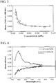
- FIG. 3 is a graph showing a relationship between a Cl concentration in the cladding layer 12 and a transmission loss of the optical fiber 1 increased by exposure to hydrogen.
- the horizontal axis of FIG. 3 represents a Cl concentration (wt%) in the cladding layer 12.
- ⁇ 2 represents a value of transmission loss of the optical fiber 1 after exposure to hydrogen under conditions of H 2 concentration: 100%, in room temperature, and for 15 hours.
- ⁇ 1 represents a value of transmission loss of the optical fiber 1 before the exposure.
- a measurement wavelength of transmission loss was 1550 nm, and the transmission loss was measured using an OTDR. That is, data of FIG. 3 was obtained by changing the Cl concentration in the cladding layer 12 in a state where the measurement wavelength of transmission loss was fixed.
- the optical fiber 1 was exposed to high-concentration H 2 as an accelerated test. Therefore, the transmission loss of the optical fiber 1 significantly increased within a short period of time.
- H 2 is present even in a natural environment such as air or water. Therefore, it is considered that the same phenomenon occurs by exposing the optical fiber 1 in a natural environment for a long period of time. That is, when this phenomenon occurs, the transmission loss increases with the passage of time after providing the optical fiber 1 as a communication cable.
- FIG. 4 shows data of two kinds of the optical fibers 1 including the optical fiber 1 (Cl: 0.027 wt%) in which the cladding layer 12 was not sufficiently dehydrated and the optical fiber 1 (Cl: 0.029 wt%) in which the cladding layer 12 was sufficiently dehydrated.
- the horizontal axis of the graph represents a measurement wavelength of transmission loss
- the vertical axis represents ⁇ Loss. That is, data of FIG. 4 was obtained by changing the measurement wavelength of transmission loss in a state where the Cl concentration in the cladding layer 12 was fixed in each of the two kinds of optical fibers 1.
- the value of ⁇ Loss was negative particularly in a measurement wavelength range of 650 nm or shorter.
- the value of ⁇ Loss being negative represents that the transmission loss was reduced by exposing the optical fiber 1 to hydrogen.
- the reason why the transmission loss was reduced is presumed to be that an oxygen defective type defect present in an ultraviolet range, for example, E' center of SiO 2 react with hydrogen, -H is arranged at the terminal of the defect, and a Si-H structure having a low absorbance appears. That is, due to the appearance of the Si-H structure having a low absorbance, the light absorption amount was reduced, and the transmission loss was reduced as compared to that before the exposure to hydrogen.
- the refractive index of the cladding layer 12 increases due to Cl included in the cladding layer 12, and it is necessary that the refractive index of the cladding layer 12 is lower than the refractive index of the core 11 by a predetermined amount.
- F is added to reduce the refractive index of the cladding layer 12
- Rayleigh scattering increases, which causes deterioration in transmission loss.
- the Cl concentration in the cladding layer may have a preferable range.
- Table 1 the result of verifying the preferable range of the Cl concentration in the cladding layer 12 and the like will be described using Table 1.
- the optical fibers 1 were prepared under a plurality of conditions (Comparative Examples 1 to 4 and Examples 1 to 9), and a relationship between the Cl concentration in the cladding layer 12 and the transmission loss was verified. The results are shown in Table 1.
- “Cladding Cl Concentration” in Table 1 shows the results of measuring the average Cl concentration in the cladding layer 12 by an electron probe microanalyzer (EPMA).
- “Cladding OH Group Concentration” of Table 1 shows the results of measuring the OH group concentration in the cladding layer 12 by an FT-IR.
- the lower detection limit of the OH group concentration by the FT-IR used herein was 10 ppm.
- “Difference in Transmission loss ( ⁇ Loss)" of Table 1 shows the value of transmission loss at a wavelength 1550 nm increased after exposing each of the optical fibers 1 to hydrogen under conditions of H 2 concentration: 100%, in room temperature (25°C to 27°C), and for 15 hours.
- Data shown in Table 1 are arranged in order from the lowest cladding Cl concentration to the highest. That is, data shown on the upper side of Table 1 was data of the optical fiber 1 in which the cladding layer 12 was weakly dehydrated, and data shown on the lower side of Table 1 was data of the optical fiber 1 in which the cladding layer 12 was strongly dehydrated.
- the Cl concentration in the cladding layer 12 is 0.029 wt% to 0.098 wt%.
- an increase in the transmission loss of the optical fiber 1 caused by exposure to hydrogen can be limited.
- an increase in the transmission loss of the optical fiber 1 can be limited.
- the cladding layer 12 includes a large amount of Cl, and an increase in refractive index is limited. Therefore, it is not necessary that the cladding layer 12 includes a large amount of fluorine or the like.
- an increase in the transmission loss of the optical fiber 1 caused by exposure to hydrogen can be limited while limiting the initial transmission loss of the optical fiber 1 to be low.
- the difference in transmission loss ( ⁇ Loss) between the value ⁇ 2 of transmission loss after exposure to hydrogen at a wavelength of 430 nm and the value ⁇ 1 of transmission loss before exposure to hydrogen at a wavelength of 430 nm is 0 dB/km or lower (refer to FIG. 4 ). That is, at a wavelength of 430 nm, ⁇ 2- ⁇ 1 ⁇ 0 dB/km is satisfied.
- the optical fiber 1 can exhibit an excellent effect in that it has a wavelength band in which the transmission loss is reduced by exposure to hydrogen.
- the optical fiber 1 can be obtained in which an increase in transmission loss caused by exposure to hydrogen can be limited even in a wavelength band used for optical communication.
- the optical fiber can be manufactured in which, when cladding layer 12 is dehydrated with Cl-containing gas such that the Cl concentration in the cladding layer 12 is 0.029 wt% to 0.098 wt%, ⁇ 1 is 0.170 dB/km or lower at a wavelength of 1550 nm, and ⁇ 2- ⁇ 1 ⁇ 0.005 dB/km. (Refer to FIG. 3 and Table 1)
- the optical fiber 1 can exhibit the above-described excellent effect while reducing the manufacturing time of the optical fiber 1.
- the optical fiber 1 can be manufactured in which the Cl concentration in the cladding layer 12 is 0.029 wt% to 0.098 wt%.
Landscapes
- Physics & Mathematics (AREA)
- Chemical & Material Sciences (AREA)
- Engineering & Computer Science (AREA)
- General Physics & Mathematics (AREA)
- Optics & Photonics (AREA)
- Materials Engineering (AREA)
- Life Sciences & Earth Sciences (AREA)
- General Life Sciences & Earth Sciences (AREA)
- Geochemistry & Mineralogy (AREA)
- Manufacturing & Machinery (AREA)
- Organic Chemistry (AREA)
- General Chemical & Material Sciences (AREA)
- Chemical Kinetics & Catalysis (AREA)
- Thermal Sciences (AREA)
- Manufacture, Treatment Of Glass Fibers (AREA)
- Optical Fibers, Optical Fiber Cores, And Optical Fiber Bundles (AREA)
Abstract
Description
- The present invention relates to an optical fiber, a method for manufacturing an optical fiber, and an optical fiber preform.
- Priority is claimed on Japanese Patent Application No.
2017-106992, filed on May 30, 2017 - In an optical fiber used in an optical communication system, in order to increase the possible transmission distance of an optical signal, it is required to improve an optical signal to noise ratio (OSNR). In order to improve the OSNR, it is important to reduce the transmission loss of an optical fiber.
- As the optical fiber, a Ge-doped core fiber in which a core is doped with germanium dioxide is generally widely used. However, in a silica core fiber not including the additives, Rayleigh scattering can be further limited as compared to the Ge-doped core fiber, and thus a further reduction in transmission loss is expected. In the silica core fiber, it is important to reduce transmission loss caused by light absorption derived from binding defects of silicon dioxide (SiO2).
- In general, in an optical fiber, transmission loss in an optical communication wavelength band increases due to light absorption of an OH group (hydroxy group) caused by binding defects of SiO2. In addition, in an optical fiber, light propagates mainly in a core. Therefore, in order to reduce transmission loss, it is necessary that the core is sufficiently dehydrated to remove an OH group. Therefore,
Patent Document 1 discloses a method of dehydrating a core by causing halogen gas such as chlorine gas (Cl2) to flow and to react with hydrogen gas (H2) when a soot deposited using a vapor-phase axial deposition method (VAD method) is sintered. In this method, the dehydration is performed during the formation of a glass preform. Therefore, initial transmission loss of an optical fiber can be reduced. -
- [Patent Document 1] Japanese Unexamined Patent Application, First Publication No.
S58-13503 - [Patent Document 2] Japanese Unexamined Patent Application, First Publication No.
2005-206452 - As a result of a thorough investigation, the present inventors clarified that, even in an optical fiber in which a core is sufficiently dehydrated and initial transmission loss is low, when dehydration of a cladding layer is insufficient, optical transmission loss increases by being exposed to H2 for a long period of time.
- On the other hand, Patent Document 2 discloses a method of dehydrating a cladding layer using SiCl4 after adding fluorine (F) to the cladding layer. However, in this method, a large amount of chlorine (CI) is added to a cladding layer such that the refractive index of the cladding layer increases due to Cl. Therefore, in order to adjust a difference in refractive index between the core and the cladding, it is necessary to add an excess amount of F to the cladding layer to reduce the refractive index of the cladding layer. As compared to Cl, F tends to further increase Rayleigh scattering due to concentration fluctuation thereof, and the presence of an excess amount of F in the cladding layer in the vicinity of the core leads to an increase in the transmission loss of the optical fiber. In addition, for example, when an increase in raw material costs for adding an excess amount of F is taken into consideration, the method disclosed in Patent Document 2 also has room for improvement.
- The present invention has been made in consideration of the above-described circumstances, and an object thereof is to provide an optical fiber in which a phenomenon of increasing transmission loss during exposure to hydrogen is limited.
- According to a first aspect of the present invention for achieving the above-described object, there is provided an optical fiber including: a core; and a cladding layer that is provided on an outer circumference of the core, in which a Cl concentration in the cladding layer is 0.029 wt% to 0.098 wt%.
- In addition, according to a second aspect of the present invention for achieving the above-described object, there is provided a method for manufacturing an optical fiber including a core and a cladding layer that is provided on an outer circumference of the core, the method including dehydrating the cladding layer with Cl-containing gas such that a Cl concentration in the cladding layer is 0.029 wt% to 0.098 wt%.
- In addition, according to a third aspect of the present invention for achieving the above-described object, there is provided an optical fiber preform for manufacturing an optical fiber including a core and a cladding layer that is provided on an outer circumference of the core, in which a Cl concentration in a soot that forms the cladding layer is 0.029 wt% to 0.098 wt%.
- According to the aspects of the present invention, an optical fiber in which a phenomenon of increasing transmission loss during exposure to hydrogen is limited can be provided.
-
-
FIG. 1 is a schematic diagram showing a cross-section of an optical fiber according to an embodiment of the present invention and a refractive index profile of each of layers. -
FIG. 2 is a schematic diagram showing a cross-section of an optical fiber according to a modification example and a refractive index profile of each of layers. -
FIG. 3 is a graph showing a relationship between a Cl concentration in a cladding layer and a difference between transmission loss values before and after exposure to hydrogen. -
FIG. 4 is a graph showing a relationship between a wavelength of light and a difference between transmission loss values before and after exposure to hydrogen. - Hereinafter, an optical fiber, a method for manufacturing an optical fiber, and an optical fiber preform according to an embodiment of the present invention will be described.
- The optical fiber according to the embodiment is an
optical fiber 1 having, for example, a stepwise refractive index profile shown inFIG. 1 or a W-shaped refractive index profile shown inFIG. 2 . The refractive index profile of theoptical fiber 1 is not limited to the example shown inFIG. 1 or 2 . - The
optical fiber 1 includes acore 11 and acladding layer 12 that is formed on an outer circumference of thecore 11. - The
optical fiber 1 is a silica core fiber in which thecore 11 is formed of silicon dioxide (SiO2) and additives such as germanium are not added. Theoptical fiber 1 shown inFIG. 1 includes thecladding layer 12 having a single-layer structure, and theoptical fiber 1 shown inFIG. 2 includes thecladding layer 12 having a multiple-layer structure including aninner cladding layer 12a and anouter cladding layer 12b. - An optical fiber preform for manufacturing the
optical fiber 1 according to the embodiment can be manufactured as follows. - First, a soot (hereinafter, referred to as "core soot") that forms the
core 11 of SiO2 is formed using a VAD method. At this time, in order to adjust the viscosity of a material that forms thecore 11, F may be added to the material using fluorine (F) -containing gas which includes fluorine, the F-containing gas such as SiF4, C2F6, SF6, or CF4. Alternatively, the material that forms thecore 11 may include alkali metal such as sodium (Na) or potassium (K). - Next, Cl-containing gas which includes chlorine, the Cl-containing gas such as SOCl2 or Cl2 is diffused and is caused to react in the core soot such that the core soot is dehydrated. Here, F or the alkali metal for adjusting the viscosity may be added to the core soot.
- Next, the dehydrated core soot is heated in a helium (He) atmosphere to be vitrified such that core glass is obtained. It is preferable that the dehydration is performed such that the core glass includes about 0.2 to 2.0 wt% of Cl. The shape of the refractive index profile of the core may become higher or lower from the outer circumference toward the inside, may be stepwise, or may be flat (uniform).
- Next, a soot (hereinafter, referred to as "cladding soot") that forms the
cladding layer 12 is formed on the outer circumference of the core glass using an outside vapor-deposition method. In the outside vapor-deposition method, "deposition" of depositing the cladding soot on the outer circumference of the core glass is performed. At this time, it is preferable that the deposition is performed in a state where the surface of the core glass is etched with etching gas such as SF6 or C2F6 to remove remaining water. During the formation of the cladding soot, the core glass and the cladding soot may be drawn in order to obtain an outer diameter in which the soot can be easily vapor-deposited. In addition, thecladding layer 12 may be vapor-deposited multiple times so as to obtain a desired outer diameter. - Next, Cl-containing gas such as SOCl2 or Cl2 and F-containing gas such as SiF4 are mixed with each other, and this mixed gas is diffused and is caused to react in the cladding soot. As a result, the dehydration treatment and the F addition treatment of the cladding soot can be simultaneously performed.
- Next, the cladding soot on which the dehydration treatment and the F addition treatment are performed is heated in a F-containing gas atmosphere to be vitrified such that the
cladding layer 12 is formed. At this time, it is preferable that thecladding layer 12 is dehydrated such that an average Cl concentration distribution in a cross-section is 0.029 wt% or higher. - On the other hand, when the amount of Cl added to the
cladding layer 12 is excessive, the transmission loss of theoptical fiber 1 may increase due to Rayleigh scattering in thecladding layer 12. In addition, when the amount of Cl added to thecladding layer 12 is excessive, it is difficult to adjust a difference in viscosity between the core 11 and thecladding layer 12 or the refractive index profile. Therefore, it is preferable that thecladding layer 12 is dehydrated such that an average Cl concentration profile in a cross-section is 0.098 wt% or lower. - That is, it is preferable that the Cl concentration in the
cladding layer 12 is 0.029 wt% to 0.098 wt%. The Cl concentration in thecladding layer 12 can be measured using a Fourier transform infrared spectrophotometer (FT-IR). - The shape of the refractive index profile and the Cl concentration distribution in the formed
cladding layer 12 may become higher or lower from the outer circumference toward the inside, may be stepwise, or may be flat (uniform). In addition, a plurality of cladding layers 12 may be formed in order to obtain a desired shape of the refractive index profile and a desired Cl concentration distribution. However, in order to form a plurality of cladding layers 12, the cladding formation using an outside vapor-deposition method is performed multiple times. Therefore, as long as optical characteristic suitable for the use can be obtained, the stepwise (FIG. 1 ) or W-shaped (FIG. 2 ) refractive index profile that can be realized with a small number of times of vapor-deposition is preferable. - By forming the
cladding layer 12 as described above, an optical fiber preform can be obtained. - In addition, by melting and drawing the optical fiber preform obtained as described above, the
optical fiber 1 can be manufactured. - Hereinafter, the embodiment will be described using specific Examples. The following Examples do not limit the present invention.
-
FIG. 3 is a graph showing a relationship between a Cl concentration in thecladding layer 12 and a transmission loss of theoptical fiber 1 increased by exposure to hydrogen. The horizontal axis ofFIG. 3 represents a Cl concentration (wt%) in thecladding layer 12. The vertical axis ofFIG. 3 represents a difference in transmission loss ΔLoss (=Δ2-Δ1). Here, Δ2 represents a value of transmission loss of theoptical fiber 1 after exposure to hydrogen under conditions of H2 concentration: 100%, in room temperature, and for 15 hours. Δ1 represents a value of transmission loss of theoptical fiber 1 before the exposure. A measurement wavelength of transmission loss was 1550 nm, and the transmission loss was measured using an OTDR. That is, data ofFIG. 3 was obtained by changing the Cl concentration in thecladding layer 12 in a state where the measurement wavelength of transmission loss was fixed. - It can be seen from
FIG. 3 that, when theoptical fiber 1 is exposed to hydrogen, the transmission loss at a wavelength of 1550 nm of theoptical fiber 1 increases. Further, it can be seen that, as the Cl concentration in thecladding layer 12 increases, ΔLoss at a wavelength of 1550 nm decreases, and when the Cl concentration in thecladding layer 12 is 0.029 wt% or higher, ΔLoss is 0.005 dB/km or lower. That is, at a wavelength of 1550 nm, Δ2-Δ1≤0.005 dB/km is satisfied. - Here, in this example, the
optical fiber 1 was exposed to high-concentration H2 as an accelerated test. Therefore, the transmission loss of theoptical fiber 1 significantly increased within a short period of time. On the other hand, H2 is present even in a natural environment such as air or water. Therefore, it is considered that the same phenomenon occurs by exposing theoptical fiber 1 in a natural environment for a long period of time. That is, when this phenomenon occurs, the transmission loss increases with the passage of time after providing theoptical fiber 1 as a communication cable. - This way, the mechanism in which the transmission loss of the
optical fiber 1 increases by exposing theoptical fiber 1 to hydrogen will be discussed below. -
FIG. 4 shows data of two kinds of theoptical fibers 1 including the optical fiber 1 (Cl: 0.027 wt%) in which thecladding layer 12 was not sufficiently dehydrated and the optical fiber 1 (Cl: 0.029 wt%) in which thecladding layer 12 was sufficiently dehydrated. InFIG. 4 , the horizontal axis of the graph represents a measurement wavelength of transmission loss, and the vertical axis represents ΔLoss. That is, data ofFIG. 4 was obtained by changing the measurement wavelength of transmission loss in a state where the Cl concentration in thecladding layer 12 was fixed in each of the two kinds ofoptical fibers 1. - As shown in
FIG. 4 , in the optical fiber 1 (Cl: 0.027 wt%) in which thecladding layer 12 was not sufficiently dehydrated, an increase in transmission loss having a peak in the vicinity of a wavelength range 430 nm to 450 nm was shown. The value of ΔLoss decreased as the measurement wavelength increased from the vicinity of a wavelength of 450 nm. However, the increase in transmission loss reached up to the vicinity of a wavelength of 1550 nm (not shown). That is, an increase in transmission loss having a peak in the vicinity of a wavelength range 430 nm to 450 nm brings about an increase in transmission loss at a wavelength in the vicinity of a wavelength of 1550 nm used for optical communication. - It is presumed that the increase in transmission loss having a peak in the vicinity of a wavelength range 430 nm to 450 nm occurs because the
cladding layer 12 is not sufficiently dehydrated. When thecladding layer 12 is not dehydrated, due to the presence of a large number of OH groups in thecladding layer 12, binding defects of SiO2 having an action of absorbing light in the vicinity of a wavelength of 430 nm to 450 nm occurs at an interface between the core 11 and thecladding layer 12. Due to the defects, the transmission loss in the vicinity of a measurement wavelength of 430 nm to 450 nm increased. - On the other hand, in the optical fiber 1 (Cl: 0.029 wt%) in which the
cladding layer 12 was dehydrated, the value of ΔLoss was negative particularly in a measurement wavelength range of 650 nm or shorter. The value of ΔLoss being negative represents that the transmission loss was reduced by exposing theoptical fiber 1 to hydrogen. - The reason why the transmission loss was reduced is presumed to be that an oxygen defective type defect present in an ultraviolet range, for example, E' center of SiO2 react with hydrogen, -H is arranged at the terminal of the defect, and a Si-H structure having a low absorbance appears. That is, due to the appearance of the Si-H structure having a low absorbance, the light absorption amount was reduced, and the transmission loss was reduced as compared to that before the exposure to hydrogen.
- As a result, an increase in transmission loss caused by exposure to hydrogen can be limited by dehydrating the
cladding layer 12. - Incidentally, when the dehydration treatment of the
cladding layer 12 caused by Cl-containing gas is excessively performed, the refractive index of thecladding layer 12 increases due to Cl included in thecladding layer 12, and it is necessary that the refractive index of thecladding layer 12 is lower than the refractive index of the core 11 by a predetermined amount. On the other hand, when F is added to reduce the refractive index of thecladding layer 12, Rayleigh scattering increases, which causes deterioration in transmission loss. Accordingly, the Cl concentration in the cladding layer may have a preferable range. Hereinafter, the result of verifying the preferable range of the Cl concentration in thecladding layer 12 and the like will be described using Table 1.[Table 1] Sample Cladding Cl Concentration *1 Cladding OH Group Concentration Transmission Loss (Δ1) before Exposure to H2 *3,4 Difference in Transmission Loss (ΔLoss) *3∼5 Comparative Example 1 W-Shaped 0.026wt% < 10ppm 2
0.169 dB/km 0.007 dB/km Comparative Example 2 W-Shaped 0.027wt% < 10ppm 0.169 dB/km 0.0075 dB/km Comparative Example 3 W-Shaped 0.027wt% < 10ppm 0.1675 dB/km 0.0065 dB/km Example 1 W-Shaped 0.029wt% < 10ppm 0.168 dB/km 0.005 dB/km Example 2 Stepwise 0.033wt% <10ppm 0.168 dB/km 0.0035 dB/km Example 3 Stepwise 0.037wt% < 10ppm 0.1675 dB/km 0.004 dB/km Example 4 W-Shaped 0.038wt% <10ppm 0.1685 dB/km 0.003 dB/km Example 5 Stepwise 0.044wt% < 10ppm 0.168 dB/km 0.003 dB/km Example 6 Stepwise 0.051wt% < 10ppm 0.170 dB/km 0.0025 dB/km Example 7 Stepwise 0.066wt% < 10ppm 0.1695 dB/km 0.002 dB/km Example 8 W-Shaped 0.074wt% < 10ppm 0.1685 dB/km 0.002 dB/km Example 9 W-Shaped 0.098wt% <10ppm 0.170 dB/km 0.0015 dB/km Comparative Example 4 W-Shaped 0.112wt% < 10ppm 0.174 dB/km 0.002 dB/km *1: EPMA, *2: FT-IR lower detection limit or lower, *3: transmission loss measurement wavelength: 1550 nm, *4: OTDR,
*5: exposure to atmosphere, H2 concentration: 100%/room temperature (25°C to 27°C)/for 15 h - The
optical fibers 1 were prepared under a plurality of conditions (Comparative Examples 1 to 4 and Examples 1 to 9), and a relationship between the Cl concentration in thecladding layer 12 and the transmission loss was verified. The results are shown in Table 1. - "Cladding Cl Concentration" in Table 1 shows the results of measuring the average Cl concentration in the
cladding layer 12 by an electron probe microanalyzer (EPMA). - "Cladding OH Group Concentration" of Table 1 shows the results of measuring the OH group concentration in the
cladding layer 12 by an FT-IR. The lower detection limit of the OH group concentration by the FT-IR used herein was 10 ppm. - "Transmission Loss (Δ1) before Exposure to H2" of Table 1 shows the results of measuring the transmission loss of each of the
optical fibers 1 by an OTDR before exposure to hydrogen, that is, in an initial state at a wavelength of 1550 nm. - "Difference in Transmission loss (ΔLoss)" of Table 1 shows the value of transmission loss at a
wavelength 1550 nm increased after exposing each of theoptical fibers 1 to hydrogen under conditions of H2 concentration: 100%, in room temperature (25°C to 27°C), and for 15 hours. - Data shown in Table 1 are arranged in order from the lowest cladding Cl concentration to the highest. That is, data shown on the upper side of Table 1 was data of the
optical fiber 1 in which thecladding layer 12 was weakly dehydrated, and data shown on the lower side of Table 1 was data of theoptical fiber 1 in which thecladding layer 12 was strongly dehydrated. - Here, focusing on the values of "ΔLoss" in Table 1, it can be seen that the difference in transmission loss (ΔLoss) of data (Examples 1 to 9) in which the cladding Cl concentration was 0.029 wt% or higher was less than those of data (Comparative Examples 1 to 3) in which the cladding Cl concentration was 0.026 to 0.027 wt%. That is, regarding the data in which the cladding concentration was 0.029 wt% or higher, ΔLoss was limited to be 0.005 dB/km or lower. However, regarding the data in which the cladding concentration was 0.027 wt% or lower, ΔLoss was relatively large at 0.065 dB/km or higher. It can be said from that above result that the cladding Cl concentration is preferably 0.029 wt% or higher.
- Next, focusing on the values of "Transmission Loss (Δ1) before Exposure to H2" of Table 1, in the data (Examples 1 to 9) in which the cladding Cl concentration was 0.098 wt% or lower, the transmission loss was limited to be 0.170 dB/km or lower. However, in the data (Comparative Example 4) in which the cladding Cl concentration was 0.112 wt%, the transmission loss was 0.174 dB/km. In Comparative Example 4, an excess amount of Cl was added to the
cladding layer 12. As a result, it was necessary to add F to reduce the refractive index of thecladding layer 12, and the initial transmission loss (Δ1) was increased due to Rayleigh scattering caused by F. It can be said from that above result that the cladding Cl concentration is preferably 0.098 wt% or lower. - In consideration of the above-described discussion, it is preferable that the Cl concentration in the
cladding layer 12 is 0.029 wt% to 0.098 wt%. - By adjusting the Cl concentration in the
cladding layer 12 to be 0.029 wt% or higher, an increase in the transmission loss of theoptical fiber 1 caused by exposure to hydrogen can be limited. As a result, when theoptical fiber 1 is exposed to hydrogen present in air or water for a long period of time after providing theoptical fiber 1 as an optical fiber cable or the like, an increase in the transmission loss of theoptical fiber 1 can be limited. - Further, by adjusting the Cl concentration in the
cladding layer 12 to be 0.098 wt% or lower, thecladding layer 12 includes a large amount of Cl, and an increase in refractive index is limited. Therefore, it is not necessary that thecladding layer 12 includes a large amount of fluorine or the like. - That is, an increase in the transmission loss of the
optical fiber 1 caused by exposure to hydrogen can be limited while limiting the initial transmission loss of theoptical fiber 1 to be low. - In addition, when the Cl concentration in the
cladding layer 12 is 0.029 wt% to 0.098 wt%, the difference in transmission loss (ΔLoss) between the value Δ2 of transmission loss after exposure to hydrogen at a wavelength of 430 nm and the value Δ1 of transmission loss before exposure to hydrogen at a wavelength of 430 nm is 0 dB/km or lower (refer toFIG. 4 ). That is, at a wavelength of 430 nm, Δ2-Δ1≤0 dB/km is satisfied. As a result, theoptical fiber 1 can exhibit an excellent effect in that it has a wavelength band in which the transmission loss is reduced by exposure to hydrogen. - In addition, when the Cl concentration in the
cladding layer 12 is 0.029 wt% to 0.098 wt%, at a wavelength of 1550 nm, Δ2-Δ1≤0.005 dB/km is satisfied (refer toFIG. 3 ). As a result, theoptical fiber 1 can be obtained in which an increase in transmission loss caused by exposure to hydrogen can be limited even in a wavelength band used for optical communication. - The optical fiber can be manufactured in which, when cladding
layer 12 is dehydrated with Cl-containing gas such that the Cl concentration in thecladding layer 12 is 0.029 wt% to 0.098 wt%, Δ1 is 0.170 dB/km or lower at a wavelength of 1550 nm, and Δ2-Δ1≤0.005 dB/km. (Refer toFIG. 3 and Table 1) - In addition, when the
cladding layer 12 is dehydrated with mixed gas of Cl-containing gas and F-containing gas, the dehydration treatment and the F addition treatment of thecladding layer 12 can be simultaneously performed. Therefore, theoptical fiber 1 can exhibit the above-described excellent effect while reducing the manufacturing time of theoptical fiber 1. - In addition, by melting and drawing the optical fiber preform in which the Cl concentration in the soot that forms the
cladding layer 12 is 0.029 wt% to 0.098 wt%, theoptical fiber 1 can be manufactured in which the Cl concentration in thecladding layer 12 is 0.029 wt% to 0.098 wt%. - As shown in Table 1, all the cladding OH group concentrations of Examples 1 to 9 and Comparative Examples 1 to 4 were 10 ppm (lower detection limit of the FT-IR) or lower.
- The technical scope of the present invention is not limited to the embodiment, and various modifications can be made within a range not departing from the scope of the present invention.
- In addition, within a range not departing from the scope of the present invention, the components according to the embodiment can be appropriately replaced with well-known components.
-
- 1: optical fiber
- 11: core
- 12: cladding layer
Claims (7)
- An optical fiber comprising:a core; anda cladding layer that is provided on an outer circumference of the core,wherein a Cl concentration in the cladding layer is 0.029 wt% to 0.098 wt%.
- The optical fiber according to claim 1,
wherein when a value of transmission loss before exposure to hydrogen is represented by Δ1 and a value of transmission loss after exposure to hydrogen is represented by Δ2, Δ2-Δ1≤0 dB/km is satisfied at a wavelength of 430 nm. - The optical fiber according to claim 1 or 2,
wherein when a value of transmission loss before exposure to hydrogen is represented by Δ1 and a value of transmission loss after exposure to hydrogen is represented by Δ2, Δ2-Δ1≤0.005 dB/km is satisfied at a wavelength of 1550 nm. - The optical fiber according to any one of claims 1 to 3,
wherein an OH group concentration in the cladding layer is 10 ppm or lower. - A method for manufacturing an optical fiber including a core and a cladding layer that is provided on an outer circumference of the core, the method comprising:
dehydrating the cladding layer with Cl-containing gas such that a Cl concentration in the cladding layer is 0.029 wt% to 0.098 wt%. - The method for manufacturing an optical fiber according to claim 5,
wherein the cladding layer is dehydrated with mixed gas of Cl-containing gas and F-containing gas. - An optical fiber preform for manufacturing an optical fiber including a core and a cladding layer that is provided on an outer circumference of the core,
wherein a Cl concentration in a soot that forms the cladding layer is 0.029 wt% to 0.098 wt%.
Applications Claiming Priority (2)
| Application Number | Priority Date | Filing Date | Title |
|---|---|---|---|
| JP2017106992A JP2018205357A (en) | 2017-05-30 | 2017-05-30 | Optical fiber, method of manufacturing optical fiber, and optical fiber preform |
| PCT/JP2018/014233 WO2018220995A1 (en) | 2017-05-30 | 2018-04-03 | Optical fiber, method for manufacturing optical fiber, and optical fiber base material |
Publications (3)
| Publication Number | Publication Date |
|---|---|
| EP3633426A1 true EP3633426A1 (en) | 2020-04-08 |
| EP3633426A4 EP3633426A4 (en) | 2021-02-24 |
| EP3633426B1 EP3633426B1 (en) | 2025-07-02 |
Family
ID=64455927
Family Applications (1)
| Application Number | Title | Priority Date | Filing Date |
|---|---|---|---|
| EP18810607.4A Active EP3633426B1 (en) | 2017-05-30 | 2018-04-03 | Optical fiber, method for manufacturing optical fiber, and optical fiber base material |
Country Status (6)
| Country | Link |
|---|---|
| US (1) | US11168015B2 (en) |
| EP (1) | EP3633426B1 (en) |
| JP (1) | JP2018205357A (en) |
| CN (1) | CN110603468B (en) |
| PL (1) | PL3633426T3 (en) |
| WO (1) | WO2018220995A1 (en) |
Families Citing this family (2)
| Publication number | Priority date | Publication date | Assignee | Title |
|---|---|---|---|---|
| JP2023510777A (en) * | 2020-01-10 | 2023-03-15 | オーエフエス ファイテル,エルエルシー | Enhanced high-temperature hydrogen scattering resistance in optical fibers |
| JP7332559B2 (en) * | 2020-09-16 | 2023-08-23 | 信越化学工業株式会社 | Manufacturing method of glass base material for optical fiber |
Family Cites Families (37)
| Publication number | Priority date | Publication date | Assignee | Title |
|---|---|---|---|---|
| US3933454A (en) | 1974-04-22 | 1976-01-20 | Corning Glass Works | Method of making optical waveguides |
| US4111525A (en) * | 1976-10-12 | 1978-09-05 | Bell Telephone Laboratories, Incorporated | Silica based optical fiber waveguide using phosphorus pentoxide and germanium dioxide |
| JPS5813503A (en) | 1981-07-15 | 1983-01-26 | Kyowa Sangyo Kk | Exterminating method of rat under snow |
| JPS6090842A (en) * | 1983-10-20 | 1985-05-22 | Sumitomo Electric Ind Ltd | Manufacture of glass base material for optical fiber |
| US4586943A (en) | 1983-10-20 | 1986-05-06 | Sumitomo Electric Industries, Ltd. | Method for the production of glass preform for optical fibers |
| EP0181595A3 (en) * | 1984-11-15 | 1986-08-06 | Polaroid Corporation | Dielectric waveguide with chlorine dopant |
| JPS61174146A (en) * | 1985-01-25 | 1986-08-05 | Sumitomo Electric Ind Ltd | Optical fiber and its manufacturing method |
| JPH05229842A (en) | 1992-01-27 | 1993-09-07 | Fujikura Ltd | Radiation resistant image fiber |
| JP3671732B2 (en) | 1992-02-07 | 2005-07-13 | 旭硝子株式会社 | ArF excimer laser, optical member for KrF excimer laser, and method for manufacturing photomask substrate |
| JP2003054995A (en) * | 2001-06-05 | 2003-02-26 | Furukawa Electric Co Ltd:The | Optical fiber preform, method for manufacturing the same, and optical fiber |
| US20020197005A1 (en) * | 2001-06-26 | 2002-12-26 | Chang Kai H. | Method and apparatus for fabricating optical fiber using adjustment of oxygen stoichiometry |
| JP2003114347A (en) * | 2001-07-30 | 2003-04-18 | Furukawa Electric Co Ltd:The | Single mode optical fiber, manufacturing method and manufacturing apparatus |
| JP4460069B2 (en) * | 2001-07-30 | 2010-05-12 | 古河電気工業株式会社 | Manufacturing method of single mode optical fiber |
| US20030221459A1 (en) | 2002-05-31 | 2003-12-04 | Walczak Wanda J. | Method for forming an optical waveguide fiber preform |
| AU2003244251A1 (en) | 2002-06-29 | 2004-01-19 | Lg Cable Ltd. | Method for fabricating optical fiber preform without hydroxyl group in core |
| JP2005181414A (en) | 2003-12-16 | 2005-07-07 | Hitachi Cable Ltd | Optical fiber manufacturing method |
| JP2005206452A (en) * | 2003-12-25 | 2005-08-04 | Sumitomo Electric Ind Ltd | Fluorine-doped silica glass body manufacturing method, optical fiber preform and optical fiber manufacturing method, and optical fiber |
| CN102583997B (en) * | 2004-11-29 | 2015-03-11 | 古河电气工业株式会社 | Optical fiber preform, method of manufacturing optical fiber preform, and method of manufacturing optical fiber |
| US7805039B2 (en) | 2007-05-04 | 2010-09-28 | Weatherford/Lamb, Inc. | Single mode optical fiber with improved bend performance |
| WO2009096557A1 (en) * | 2008-01-30 | 2009-08-06 | Asahi Glass Co., Ltd. | Optical fiber preform used for energy transmission or ultraviolet light transmission and method of manufacturing the optical fiber preform |
| US8315495B2 (en) | 2009-01-30 | 2012-11-20 | Corning Incorporated | Large effective area fiber with Ge-free core |
| US8542969B2 (en) | 2010-02-26 | 2013-09-24 | Corning Incorporated | Low bend loss optical fiber |
| JP5771943B2 (en) * | 2010-10-18 | 2015-09-02 | 住友電気工業株式会社 | Optical fiber and method for manufacturing glass preform for optical fiber |
| RU2614033C2 (en) * | 2011-08-19 | 2017-03-22 | Корнинг Инкорпорейтед | Low bending loss optical fibre |
| JP2013061559A (en) * | 2011-09-14 | 2013-04-04 | Sumitomo Electric Ind Ltd | Optical fiber |
| US8565567B2 (en) * | 2011-11-23 | 2013-10-22 | Sumitomo Electric Industries, Ltd. | Multi-mode optical fiber |
| KR20130116009A (en) * | 2012-04-12 | 2013-10-22 | 신에쓰 가가꾸 고교 가부시끼가이샤 | Optical fiber |
| JP6048105B2 (en) * | 2012-12-12 | 2016-12-21 | 住友電気工業株式会社 | Optical fiber manufacturing method and optical fiber |
| US9188736B2 (en) | 2013-04-08 | 2015-11-17 | Corning Incorporated | Low bend loss optical fiber |
| GB2526590A (en) * | 2014-05-29 | 2015-12-02 | Fibercore Ltd | Optical fiber and method of producing an optical fiber |
| US9650281B2 (en) * | 2014-07-09 | 2017-05-16 | Corning Incorporated | Optical fiber with reducing hydrogen sensitivity |
| US9586853B2 (en) * | 2014-07-09 | 2017-03-07 | Corning Incorporated | Method of making optical fibers in a reducing atmosphere |
| JP6306690B2 (en) | 2014-09-26 | 2018-04-04 | 株式会社フジクラ | Optical fiber |
| US9599769B2 (en) * | 2014-11-04 | 2017-03-21 | Verrillon, Inc. | Hydrogen-resistant optical fiber |
| JP2017024917A (en) * | 2015-07-15 | 2017-02-02 | 株式会社フジクラ | Optical fiber preform, optical fiber, and optical fiber manufacturing method |
| JP7049252B2 (en) | 2015-09-15 | 2022-04-06 | コーニング インコーポレイテッド | Low bending loss single-mode fiber optics with chlorine updoping clad |
| JP6703773B2 (en) | 2015-12-08 | 2020-06-03 | 株式会社小泉製作所 | bell |
-
2017
- 2017-05-30 JP JP2017106992A patent/JP2018205357A/en active Pending
-
2018
- 2018-04-03 PL PL18810607.4T patent/PL3633426T3/en unknown
- 2018-04-03 CN CN201880028530.3A patent/CN110603468B/en active Active
- 2018-04-03 WO PCT/JP2018/014233 patent/WO2018220995A1/en not_active Ceased
- 2018-04-03 US US16/498,585 patent/US11168015B2/en active Active
- 2018-04-03 EP EP18810607.4A patent/EP3633426B1/en active Active
Also Published As
| Publication number | Publication date |
|---|---|
| WO2018220995A1 (en) | 2018-12-06 |
| CN110603468A (en) | 2019-12-20 |
| US11168015B2 (en) | 2021-11-09 |
| EP3633426A4 (en) | 2021-02-24 |
| EP3633426B1 (en) | 2025-07-02 |
| JP2018205357A (en) | 2018-12-27 |
| PL3633426T3 (en) | 2025-09-22 |
| CN110603468B (en) | 2022-01-04 |
| US20200048137A1 (en) | 2020-02-13 |
Similar Documents
| Publication | Publication Date | Title |
|---|---|---|
| EP1845398B1 (en) | Radiation resistant single-mode optical fiber and method of manufacturing thereof | |
| KR102126089B1 (en) | Optical fiber and silica glass preform for optical fiber | |
| US9335465B2 (en) | Optical fiber and optical fiber preform | |
| US20120033924A1 (en) | Low loss optical fiber designs and methods for their manufacture | |
| EP2910533A1 (en) | Optical fiber and method for producing optical fiber preform | |
| EP3438715A1 (en) | Optical fiber and method for manufacturing same | |
| EP3290973A1 (en) | Ultralow-attenuation bend-insensitive single-mode optical fibre | |
| EP2933240B1 (en) | Optical fiber manufacturing method and optical fiber | |
| US6289161B1 (en) | Optical component containing a maximum of 200 wt.-ppm of chlorine | |
| CN104714273A (en) | Low-attenuation and few-mode fiber | |
| CN107357004B (en) | Low-attenuation single-mode optical fiber and preparation method thereof | |
| EP3633426B1 (en) | Optical fiber, method for manufacturing optical fiber, and optical fiber base material | |
| US20130302001A1 (en) | Low-loss optical fiber over wide wavelength range and method of manufacturing the same | |
| EP2829522B1 (en) | Method for producing optical fiber | |
| EP2535319A2 (en) | Method for producing optical fiber | |
| KR102944739B1 (en) | Optical fiber | |
| JP7677153B2 (en) | Optical Fiber | |
| JP7527114B2 (en) | Optical Fiber | |
| US11378738B2 (en) | Optical fiber | |
| EP2889275A1 (en) | Method for producing deuterium-treated optical fiber, and deuterium-treated optical fiber | |
| CN115201961A (en) | G.654.E optical fiber for land and manufacturing process thereof | |
| JP2005181414A (en) | Optical fiber manufacturing method | |
| JP4459875B2 (en) | Optical fiber preform and manufacturing method thereof, and optical fiber manufacturing method | |
| WO2024247623A1 (en) | Multicore optical fiber | |
| CN116974003A (en) | A low-attenuation large-mode field diameter bend-insensitive single-mode optical fiber and its preparation method |
Legal Events
| Date | Code | Title | Description |
|---|---|---|---|
| STAA | Information on the status of an ep patent application or granted ep patent |
Free format text: STATUS: THE INTERNATIONAL PUBLICATION HAS BEEN MADE |
|
| PUAI | Public reference made under article 153(3) epc to a published international application that has entered the european phase |
Free format text: ORIGINAL CODE: 0009012 |
|
| STAA | Information on the status of an ep patent application or granted ep patent |
Free format text: STATUS: REQUEST FOR EXAMINATION WAS MADE |
|
| 17P | Request for examination filed |
Effective date: 20190925 |
|
| AK | Designated contracting states |
Kind code of ref document: A1 Designated state(s): AL AT BE BG CH CY CZ DE DK EE ES FI FR GB GR HR HU IE IS IT LI LT LU LV MC MK MT NL NO PL PT RO RS SE SI SK SM TR |
|
| AX | Request for extension of the european patent |
Extension state: BA ME |
|
| DAV | Request for validation of the european patent (deleted) | ||
| DAX | Request for extension of the european patent (deleted) | ||
| A4 | Supplementary search report drawn up and despatched |
Effective date: 20210125 |
|
| RIC1 | Information provided on ipc code assigned before grant |
Ipc: G02B 6/02 20060101AFI20210119BHEP Ipc: G02B 6/036 20060101ALI20210119BHEP Ipc: C03B 37/027 20060101ALI20210119BHEP Ipc: C03B 37/014 20060101ALI20210119BHEP Ipc: C03B 37/018 20060101ALI20210119BHEP |
|
| GRAP | Despatch of communication of intention to grant a patent |
Free format text: ORIGINAL CODE: EPIDOSNIGR1 |
|
| STAA | Information on the status of an ep patent application or granted ep patent |
Free format text: STATUS: GRANT OF PATENT IS INTENDED |
|
| INTG | Intention to grant announced |
Effective date: 20250226 |
|
| GRAS | Grant fee paid |
Free format text: ORIGINAL CODE: EPIDOSNIGR3 |
|
| GRAA | (expected) grant |
Free format text: ORIGINAL CODE: 0009210 |
|
| STAA | Information on the status of an ep patent application or granted ep patent |
Free format text: STATUS: THE PATENT HAS BEEN GRANTED |
|
| AK | Designated contracting states |
Kind code of ref document: B1 Designated state(s): AL AT BE BG CH CY CZ DE DK EE ES FI FR GB GR HR HU IE IS IT LI LT LU LV MC MK MT NL NO PL PT RO RS SE SI SK SM TR |
|
| RAP3 | Party data changed (applicant data changed or rights of an application transferred) |
Owner name: FUJIKURA LTD. |
|
| REG | Reference to a national code |
Ref country code: GB Ref legal event code: FG4D |
|
| P01 | Opt-out of the competence of the unified patent court (upc) registered |
Free format text: CASE NUMBER: APP_26093/2025 Effective date: 20250602 |
|
| REG | Reference to a national code |
Ref country code: CH Ref legal event code: EP |
|
| REG | Reference to a national code |
Ref country code: DE Ref legal event code: R096 Ref document number: 602018083247 Country of ref document: DE |
|
| REG | Reference to a national code |
Ref country code: IE Ref legal event code: FG4D |
|
| REG | Reference to a national code |
Ref country code: NL Ref legal event code: MP Effective date: 20250702 |
|
| PG25 | Lapsed in a contracting state [announced via postgrant information from national office to epo] |
Ref country code: PT Free format text: LAPSE BECAUSE OF FAILURE TO SUBMIT A TRANSLATION OF THE DESCRIPTION OR TO PAY THE FEE WITHIN THE PRESCRIBED TIME-LIMIT Effective date: 20251103 |
|
| PG25 | Lapsed in a contracting state [announced via postgrant information from national office to epo] |
Ref country code: NL Free format text: LAPSE BECAUSE OF FAILURE TO SUBMIT A TRANSLATION OF THE DESCRIPTION OR TO PAY THE FEE WITHIN THE PRESCRIBED TIME-LIMIT Effective date: 20250702 |
|
| REG | Reference to a national code |
Ref country code: AT Ref legal event code: MK05 Ref document number: 1809861 Country of ref document: AT Kind code of ref document: T Effective date: 20250702 |
|
| PG25 | Lapsed in a contracting state [announced via postgrant information from national office to epo] |
Ref country code: IS Free format text: LAPSE BECAUSE OF FAILURE TO SUBMIT A TRANSLATION OF THE DESCRIPTION OR TO PAY THE FEE WITHIN THE PRESCRIBED TIME-LIMIT Effective date: 20251102 |
|
| PG25 | Lapsed in a contracting state [announced via postgrant information from national office to epo] |
Ref country code: NO Free format text: LAPSE BECAUSE OF FAILURE TO SUBMIT A TRANSLATION OF THE DESCRIPTION OR TO PAY THE FEE WITHIN THE PRESCRIBED TIME-LIMIT Effective date: 20251002 |
|
| REG | Reference to a national code |
Ref country code: LT Ref legal event code: MG9D |
|
| PG25 | Lapsed in a contracting state [announced via postgrant information from national office to epo] |
Ref country code: AT Free format text: LAPSE BECAUSE OF FAILURE TO SUBMIT A TRANSLATION OF THE DESCRIPTION OR TO PAY THE FEE WITHIN THE PRESCRIBED TIME-LIMIT Effective date: 20250702 |
|
| PG25 | Lapsed in a contracting state [announced via postgrant information from national office to epo] |
Ref country code: FI Free format text: LAPSE BECAUSE OF FAILURE TO SUBMIT A TRANSLATION OF THE DESCRIPTION OR TO PAY THE FEE WITHIN THE PRESCRIBED TIME-LIMIT Effective date: 20250702 |
|
| PG25 | Lapsed in a contracting state [announced via postgrant information from national office to epo] |
Ref country code: HR Free format text: LAPSE BECAUSE OF FAILURE TO SUBMIT A TRANSLATION OF THE DESCRIPTION OR TO PAY THE FEE WITHIN THE PRESCRIBED TIME-LIMIT Effective date: 20250702 |
|
| PG25 | Lapsed in a contracting state [announced via postgrant information from national office to epo] |
Ref country code: GR Free format text: LAPSE BECAUSE OF FAILURE TO SUBMIT A TRANSLATION OF THE DESCRIPTION OR TO PAY THE FEE WITHIN THE PRESCRIBED TIME-LIMIT Effective date: 20251003 |
|
| PG25 | Lapsed in a contracting state [announced via postgrant information from national office to epo] |
Ref country code: CZ Free format text: LAPSE BECAUSE OF FAILURE TO SUBMIT A TRANSLATION OF THE DESCRIPTION OR TO PAY THE FEE WITHIN THE PRESCRIBED TIME-LIMIT Effective date: 20250702 Ref country code: SE Free format text: LAPSE BECAUSE OF FAILURE TO SUBMIT A TRANSLATION OF THE DESCRIPTION OR TO PAY THE FEE WITHIN THE PRESCRIBED TIME-LIMIT Effective date: 20250702 |
|
| PG25 | Lapsed in a contracting state [announced via postgrant information from national office to epo] |
Ref country code: LV Free format text: LAPSE BECAUSE OF FAILURE TO SUBMIT A TRANSLATION OF THE DESCRIPTION OR TO PAY THE FEE WITHIN THE PRESCRIBED TIME-LIMIT Effective date: 20250702 |
|
| PG25 | Lapsed in a contracting state [announced via postgrant information from national office to epo] |
Ref country code: BG Free format text: LAPSE BECAUSE OF FAILURE TO SUBMIT A TRANSLATION OF THE DESCRIPTION OR TO PAY THE FEE WITHIN THE PRESCRIBED TIME-LIMIT Effective date: 20250702 |
|
| PG25 | Lapsed in a contracting state [announced via postgrant information from national office to epo] |
Ref country code: RS Free format text: LAPSE BECAUSE OF FAILURE TO SUBMIT A TRANSLATION OF THE DESCRIPTION OR TO PAY THE FEE WITHIN THE PRESCRIBED TIME-LIMIT Effective date: 20251002 |
|
| PG25 | Lapsed in a contracting state [announced via postgrant information from national office to epo] |
Ref country code: ES Free format text: LAPSE BECAUSE OF FAILURE TO SUBMIT A TRANSLATION OF THE DESCRIPTION OR TO PAY THE FEE WITHIN THE PRESCRIBED TIME-LIMIT Effective date: 20250702 |
|
| PG25 | Lapsed in a contracting state [announced via postgrant information from national office to epo] |
Ref country code: SM Free format text: LAPSE BECAUSE OF FAILURE TO SUBMIT A TRANSLATION OF THE DESCRIPTION OR TO PAY THE FEE WITHIN THE PRESCRIBED TIME-LIMIT Effective date: 20250702 |
|
| PG25 | Lapsed in a contracting state [announced via postgrant information from national office to epo] |
Ref country code: DK Free format text: LAPSE BECAUSE OF FAILURE TO SUBMIT A TRANSLATION OF THE DESCRIPTION OR TO PAY THE FEE WITHIN THE PRESCRIBED TIME-LIMIT Effective date: 20250702 |
|
| PG25 | Lapsed in a contracting state [announced via postgrant information from national office to epo] |
Ref country code: IT Free format text: LAPSE BECAUSE OF FAILURE TO SUBMIT A TRANSLATION OF THE DESCRIPTION OR TO PAY THE FEE WITHIN THE PRESCRIBED TIME-LIMIT Effective date: 20250702 |
|
| PGFP | Annual fee paid to national office [announced via postgrant information from national office to epo] |
Ref country code: FR Payment date: 20260309 Year of fee payment: 9 |
|
| PGFP | Annual fee paid to national office [announced via postgrant information from national office to epo] |
Ref country code: PL Payment date: 20260311 Year of fee payment: 9 |
|
| PG25 | Lapsed in a contracting state [announced via postgrant information from national office to epo] |
Ref country code: SK Free format text: LAPSE BECAUSE OF FAILURE TO SUBMIT A TRANSLATION OF THE DESCRIPTION OR TO PAY THE FEE WITHIN THE PRESCRIBED TIME-LIMIT Effective date: 20250702 Ref country code: EE Free format text: LAPSE BECAUSE OF FAILURE TO SUBMIT A TRANSLATION OF THE DESCRIPTION OR TO PAY THE FEE WITHIN THE PRESCRIBED TIME-LIMIT Effective date: 20250702 |