EP3633403A1 - Object sensor including pitch compensation - Google Patents
Object sensor including pitch compensation Download PDFInfo
- Publication number
- EP3633403A1 EP3633403A1 EP19198839.3A EP19198839A EP3633403A1 EP 3633403 A1 EP3633403 A1 EP 3633403A1 EP 19198839 A EP19198839 A EP 19198839A EP 3633403 A1 EP3633403 A1 EP 3633403A1
- Authority
- EP
- European Patent Office
- Prior art keywords
- reflectors
- radiation
- detector
- reflecting material
- orientation
- Prior art date
- Legal status (The legal status is an assumption and is not a legal conclusion. Google has not performed a legal analysis and makes no representation as to the accuracy of the status listed.)
- Granted
Links
Images

Classifications
-
- G—PHYSICS
- G01—MEASURING; TESTING
- G01S—RADIO DIRECTION-FINDING; RADIO NAVIGATION; DETERMINING DISTANCE OR VELOCITY BY USE OF RADIO WAVES; LOCATING OR PRESENCE-DETECTING BY USE OF THE REFLECTION OR RERADIATION OF RADIO WAVES; ANALOGOUS ARRANGEMENTS USING OTHER WAVES
- G01S13/00—Systems using the reflection or reradiation of radio waves, e.g. radar systems; Analogous systems using reflection or reradiation of waves whose nature or wavelength is irrelevant or unspecified
- G01S13/88—Radar or analogous systems specially adapted for specific applications
- G01S13/93—Radar or analogous systems specially adapted for specific applications for anti-collision purposes
- G01S13/931—Radar or analogous systems specially adapted for specific applications for anti-collision purposes of land vehicles
-
- G—PHYSICS
- G01—MEASURING; TESTING
- G01S—RADIO DIRECTION-FINDING; RADIO NAVIGATION; DETERMINING DISTANCE OR VELOCITY BY USE OF RADIO WAVES; LOCATING OR PRESENCE-DETECTING BY USE OF THE REFLECTION OR RERADIATION OF RADIO WAVES; ANALOGOUS ARRANGEMENTS USING OTHER WAVES
- G01S7/00—Details of systems according to groups G01S13/00, G01S15/00, G01S17/00
- G01S7/02—Details of systems according to groups G01S13/00, G01S15/00, G01S17/00 of systems according to group G01S13/00
- G01S7/03—Details of HF subsystems specially adapted therefor, e.g. common to transmitter and receiver
-
- H—ELECTRICITY
- H01—ELECTRIC ELEMENTS
- H01Q—ANTENNAS, i.e. RADIO AERIALS
- H01Q1/00—Details of, or arrangements associated with, antennas
- H01Q1/27—Adaptation for use in or on movable bodies
- H01Q1/32—Adaptation for use in or on road or rail vehicles
- H01Q1/3208—Adaptation for use in or on road or rail vehicles characterised by the application wherein the antenna is used
- H01Q1/3233—Adaptation for use in or on road or rail vehicles characterised by the application wherein the antenna is used particular used as part of a sensor or in a security system, e.g. for automotive radar, navigation systems
-
- G—PHYSICS
- G01—MEASURING; TESTING
- G01S—RADIO DIRECTION-FINDING; RADIO NAVIGATION; DETERMINING DISTANCE OR VELOCITY BY USE OF RADIO WAVES; LOCATING OR PRESENCE-DETECTING BY USE OF THE REFLECTION OR RERADIATION OF RADIO WAVES; ANALOGOUS ARRANGEMENTS USING OTHER WAVES
- G01S7/00—Details of systems according to groups G01S13/00, G01S15/00, G01S17/00
- G01S7/02—Details of systems according to groups G01S13/00, G01S15/00, G01S17/00 of systems according to group G01S13/00
-
- G—PHYSICS
- G01—MEASURING; TESTING
- G01S—RADIO DIRECTION-FINDING; RADIO NAVIGATION; DETERMINING DISTANCE OR VELOCITY BY USE OF RADIO WAVES; LOCATING OR PRESENCE-DETECTING BY USE OF THE REFLECTION OR RERADIATION OF RADIO WAVES; ANALOGOUS ARRANGEMENTS USING OTHER WAVES
- G01S7/00—Details of systems according to groups G01S13/00, G01S15/00, G01S17/00
- G01S7/02—Details of systems according to groups G01S13/00, G01S15/00, G01S17/00 of systems according to group G01S13/00
- G01S7/03—Details of HF subsystems specially adapted therefor, e.g. common to transmitter and receiver
- G01S7/032—Constructional details for solid-state radar subsystems
-
- G—PHYSICS
- G01—MEASURING; TESTING
- G01S—RADIO DIRECTION-FINDING; RADIO NAVIGATION; DETERMINING DISTANCE OR VELOCITY BY USE OF RADIO WAVES; LOCATING OR PRESENCE-DETECTING BY USE OF THE REFLECTION OR RERADIATION OF RADIO WAVES; ANALOGOUS ARRANGEMENTS USING OTHER WAVES
- G01S7/00—Details of systems according to groups G01S13/00, G01S15/00, G01S17/00
- G01S7/02—Details of systems according to groups G01S13/00, G01S15/00, G01S17/00 of systems according to group G01S13/00
- G01S7/40—Means for monitoring or calibrating
- G01S7/4004—Means for monitoring or calibrating of parts of a radar system
- G01S7/4026—Antenna boresight
-
- G—PHYSICS
- G01—MEASURING; TESTING
- G01S—RADIO DIRECTION-FINDING; RADIO NAVIGATION; DETERMINING DISTANCE OR VELOCITY BY USE OF RADIO WAVES; LOCATING OR PRESENCE-DETECTING BY USE OF THE REFLECTION OR RERADIATION OF RADIO WAVES; ANALOGOUS ARRANGEMENTS USING OTHER WAVES
- G01S7/00—Details of systems according to groups G01S13/00, G01S15/00, G01S17/00
- G01S7/02—Details of systems according to groups G01S13/00, G01S15/00, G01S17/00 of systems according to group G01S13/00
- G01S7/40—Means for monitoring or calibrating
- G01S7/4004—Means for monitoring or calibrating of parts of a radar system
- G01S7/4026—Antenna boresight
- G01S7/4034—Antenna boresight in elevation, i.e. in the vertical plane
-
- G—PHYSICS
- G01—MEASURING; TESTING
- G01S—RADIO DIRECTION-FINDING; RADIO NAVIGATION; DETERMINING DISTANCE OR VELOCITY BY USE OF RADIO WAVES; LOCATING OR PRESENCE-DETECTING BY USE OF THE REFLECTION OR RERADIATION OF RADIO WAVES; ANALOGOUS ARRANGEMENTS USING OTHER WAVES
- G01S7/00—Details of systems according to groups G01S13/00, G01S15/00, G01S17/00
- G01S7/48—Details of systems according to groups G01S13/00, G01S15/00, G01S17/00 of systems according to group G01S17/00
- G01S7/481—Constructional features, e.g. arrangements of optical elements
- G01S7/4814—Constructional features, e.g. arrangements of optical elements of transmitters alone
- G01S7/4815—Constructional features, e.g. arrangements of optical elements of transmitters alone using multiple transmitters
-
- G—PHYSICS
- G01—MEASURING; TESTING
- G01S—RADIO DIRECTION-FINDING; RADIO NAVIGATION; DETERMINING DISTANCE OR VELOCITY BY USE OF RADIO WAVES; LOCATING OR PRESENCE-DETECTING BY USE OF THE REFLECTION OR RERADIATION OF RADIO WAVES; ANALOGOUS ARRANGEMENTS USING OTHER WAVES
- G01S7/00—Details of systems according to groups G01S13/00, G01S15/00, G01S17/00
- G01S7/48—Details of systems according to groups G01S13/00, G01S15/00, G01S17/00 of systems according to group G01S17/00
- G01S7/481—Constructional features, e.g. arrangements of optical elements
- G01S7/4817—Constructional features, e.g. arrangements of optical elements relating to scanning
-
- G—PHYSICS
- G01—MEASURING; TESTING
- G01S—RADIO DIRECTION-FINDING; RADIO NAVIGATION; DETERMINING DISTANCE OR VELOCITY BY USE OF RADIO WAVES; LOCATING OR PRESENCE-DETECTING BY USE OF THE REFLECTION OR RERADIATION OF RADIO WAVES; ANALOGOUS ARRANGEMENTS USING OTHER WAVES
- G01S7/00—Details of systems according to groups G01S13/00, G01S15/00, G01S17/00
- G01S7/48—Details of systems according to groups G01S13/00, G01S15/00, G01S17/00 of systems according to group G01S17/00
- G01S7/497—Means for monitoring or calibrating
-
- H—ELECTRICITY
- H01—ELECTRIC ELEMENTS
- H01Q—ANTENNAS, i.e. RADIO AERIALS
- H01Q1/00—Details of, or arrangements associated with, antennas
- H01Q1/12—Supports; Mounting means
- H01Q1/125—Means for positioning
- H01Q1/1264—Adjusting different parts or elements of an aerial unit
-
- H—ELECTRICITY
- H01—ELECTRIC ELEMENTS
- H01Q—ANTENNAS, i.e. RADIO AERIALS
- H01Q1/00—Details of, or arrangements associated with, antennas
- H01Q1/36—Structural form of radiating elements, e.g. cone, spiral, umbrella; Particular materials used therewith
- H01Q1/364—Structural form of radiating elements, e.g. cone, spiral, umbrella; Particular materials used therewith using a particular conducting material, e.g. superconductor
-
- H—ELECTRICITY
- H01—ELECTRIC ELEMENTS
- H01Q—ANTENNAS, i.e. RADIO AERIALS
- H01Q19/00—Combinations of primary active antenna elements and units with secondary devices, e.g. with quasi-optical devices, for giving the antenna a desired directional characteristic
- H01Q19/10—Combinations of primary active antenna elements and units with secondary devices, e.g. with quasi-optical devices, for giving the antenna a desired directional characteristic using reflecting surfaces
- H01Q19/18—Combinations of primary active antenna elements and units with secondary devices, e.g. with quasi-optical devices, for giving the antenna a desired directional characteristic using reflecting surfaces having two or more spaced reflecting surfaces
-
- H—ELECTRICITY
- H01—ELECTRIC ELEMENTS
- H01Q—ANTENNAS, i.e. RADIO AERIALS
- H01Q3/00—Arrangements for changing or varying the orientation or the shape of the directional pattern of the waves radiated from an antenna or antenna system
- H01Q3/02—Arrangements for changing or varying the orientation or the shape of the directional pattern of the waves radiated from an antenna or antenna system using mechanical movement of antenna or antenna system as a whole
- H01Q3/08—Arrangements for changing or varying the orientation or the shape of the directional pattern of the waves radiated from an antenna or antenna system using mechanical movement of antenna or antenna system as a whole for varying two co-ordinates of the orientation
Definitions
- cruise control systems may incorporate RADAR or light detection and ranging (LIDAR) for detecting an object or another vehicle in the pathway of a vehicle.
- LIDAR light detection and ranging
- the cruise control setting may be automatically adjusted to reduce the speed of the vehicle based on detecting another vehicle in the pathway of the vehicle.
- An illustrative example detector for use on a vehicle includes a radiation emitter having a near field region that is defined at least in part by a wavelength of radiation emitted by the radiation emitter.
- a radiation steering device includes a plurality of reflectors, an actuator, and a controller.
- the plurality of reflectors are situated to reflect the radiation emitted by the radiation emitter.
- the reflectors are in the near field region and have at least one characteristic that limits any phase shift of the emitted radiation reflected from the reflectors.
- the actuator is configured to adjust an orientation of the plurality of reflectors.
- the controller is configured to determine an orientation of the plurality of reflectors relative to the radiation emitter to steer the emitted radiation reflected from the reflectors in a determined direction.
- the controller is configured to control the actuator to achieve the determined orientation.
- the at least one characteristic of the plurality of reflectors comprises an index of refraction of a reflecting material of the reflectors and the index of refraction is less than 1.
- the at least one characteristic of the plurality of reflectors comprises a thickness of the reflecting material and the thickness is greater than a skin depth corresponding to a distance that the emitted radiation penetrates the reflecting material.
- the thickness is at least 5 times greater than the skin depth.
- the distance that the emitted radiation penetrates the reflecting material is based on the wavelength of the emitted radiation, a resistivity of the reflecting material and a relative permeability of the reflecting material.
- the reflecting material has a critical angle based on the index of refraction and the controller is configured to determine the orientation of the plurality of reflectors relative to the radiation emitter such than an angle of incidence of the emitted radiation approaching the reflectors is larger than the critical angle.
- the plurality of reflectors comprise a reflecting material and the reflecting material comprises at least one of gold, copper or silver.
- the plurality of reflectors comprise a reflecting material and the reflecting material comprises a mesh.
- the detector is supported on a vehicle
- the controller is configured to receive an indication of a pitch angle of the vehicle, and the controller determines the orientation of the plurality of reflectors based on the pitch angle of the vehicle.
- the controller is configured to control the actuator to dynamically adjust the orientation of the plurality of reflectors based on changes in the pitch angle of the vehicle.
- the orientation is the same for all of the reflectors.
- the plurality of reflectors comprises a plurality of moveable louvers and the actuator adjusts the orientation the plurality of moveable louvers simultaneously.
- An illustrative example method of directing radiation emitted by a detector having a near field region that is defined at least in part by a wavelength of radiation emitted by the detector includes determining a direction for the radiation and adjusting an orientation of a plurality of reflectors to steer the radiation emitted by the detector and reflected from the reflectors in the determined direction.
- the plurality of reflectors are in the near field region and have at least one characteristic that limits any phase shift of the emitted radiation reflected from the reflectors.
- the detector is supported on a vehicle and the method comprises determining a pitch angle of the vehicle and determining the orientation of the plurality of reflectors based on the pitch angle of the vehicle.
- An embodiment having one or more features of the method of any of the previous paragraphs includes dynamically adjusting the orientation of the plurality of reflectors based on changes in the pitch angle of the vehicle.
- An embodiment having one or more features of the method of any of the previous paragraphs includes adjusting the orientation of all of the reflectors simultaneously and wherein the orientation of all of the reflectors is the same relative to the detector.
- the at least one characteristic of the plurality of reflectors comprises an index of refraction of a reflecting material of the reflectors and the index of refraction is less than 1.
- the at least one characteristic of the plurality of reflectors comprises a thickness of the reflecting material, the thickness is greater than a skin depth corresponding to a distance that the emitted radiation penetrates the reflecting material, and the distance that the emitted radiation penetrates the reflecting material is based on the wavelength of the emitted radiation, a resistivity of the reflecting material and a relative permeability of the reflecting material.
- the reflecting material has a critical angle based on the index of refraction and the controller is configured to determine the orientation of the plurality of reflectors relative to the radiation emitter such than an angle of incidence of the emitted radiation approaching the reflectors is larger than the critical angle.
- the plurality of reflectors comprise a reflecting material and the reflecting material comprises a mesh.
- FIG 1 schematically illustrates a detector 20 on a vehicle 22.
- the detector 20 is useful for detecting objects in a vicinity of the vehicle 22. While the detector 20 may take various forms, for discussion purposes, the detector 20 is considered a radar detector that utilizes known radar techniques.
- the detector 20 has a field of view schematically shown at 24.
- the field of view 24 is adjustable in a vertical direction as shown by the arrows 26.
- the field of view 24 is dynamically adjustable to compensate for changes in the pitch angle of the vehicle 22, which is represented at 28 in Figure 1 . Adjusting the field of view 24 provides angular compensation to offset vehicle pitch motion so that the field of view 24 is directed along a desired trajectory from the detector 22 without requiring an expanded vertical field.
- FIGS. 2 and 3 illustrate selected features of an example embodiment of the detector 20.
- a radiation emitter 30 comprises a plurality of radar antenna elements in this example.
- a plurality of reflectors 32 are situated in a near field region of the radiation emitter 30.
- the near field region is based, at least in part, on the wavelength of the radiation emitted by the radiation emitter 30.
- the near field boundary is defined by 2 ⁇ D/ ⁇ , where D is the aperture diameter of the antenna and ⁇ is the wavelength of the emitted radiation.
- the area between the near field boundary and the emitter 30 is the near field region and fits within a distance of approximately twice the wavelength from the emitter 30.
- a long-range radar wavelength useful on the vehicle 22 of 76GHz has an associated near field region of approximately 8 millimeters.
- the reflectors 32 are situated within that 8 millimeter space.
- the reflectors 32 have at least one characteristic that limits any phase shift of the emitted radiation reflected from the reflectors 32. In the illustrated example embodiment, there is no phase shift of the emitted radiation reflected from the reflectors 32. Avoiding or minimizing any phase shift avoids any requirement for further adaptations to compensate for such phase shift and maintains radar performance as expected from the design of the emitter 30.
- the reflectors 32 include a reflecting material on at least one surface.
- the reflecting material has an index of refraction that is less than 1.
- the reflecting material in some embodiments comprises a metal, such as gold, copper, or silver.
- Gold has a refractive index of about 0.3
- copper has a refractive index of about 0.5
- silver has a refractive index of about 0.2. Utilizing a reflecting material with a refractive index less than 1 over the emitter wavelength bandpass avoids any phase change of the electrical field of the emitted radiation that is reflected from the reflectors 32.
- the reflectors 32 are also designed and situated relative to the radiation emitter 30 so that the angle of incidence of the emitted radiation approaching the reflectors 32 is larger than the critical angle of the reflecting material.
- a critical angle of a reflecting material is determined by the arcsine of the refractive index of that material. Controlling the angle of incidence in this manner allows the electrical field and magnetic field of the emitted radiation to reflect from the reflectors 32 at an angle equal to the incidence angle with no phase change after penetrating the surface of the reflecting material for a small distance.
- the amount of penetration is based on the wavelength of the radiation, the resistivity of the reflecting material, and the relative permeability of the reflecting material.
- the penetration distance may be referred to as the skin depth of the reflecting material.
- the skin depth of such reflecting materials may be determined in a known manner.
- the reflectors 32 have a thickness that is at least five times the skin depth of the reflecting material such that when the angle of incidence is greater than the critical angle of the reflecting material the emitted radiation reflected from the reflectors 32 will effectively have no phase change relative to the electromagnetic field in the near field region of the radiation emitter 30.
- reflectors 32 having gold reflecting material have an associated critical angle of 15.7 degrees. With a skin depth of about 1.7 microns and a minimum thickness of the reflecting material of 8.6 microns, the reflectors 32 do not introduce any undesired phase shift.
- Another example embodiment includes a copper reflecting material with a critical angle of 27.4 degrees, a skin depth of 1.5 microns and a thickness of 7.5 microns.
- Another example embodiment includes silver as the reflecting material having a critical angle of 8.6 degrees, a skin depth of 1.5 microns, and a thickness of 7.3 microns. With such reflectors 32, the electromagnetic field of the radiation emitted by the radiation emitter 30, whose oscillations contain electric and magnetic fields that are perpendicular to each other, will not be phase shifted when reflected from the reflectors 32.
- a supporting structure 34 supports the reflectors 32 so that each of them has the same orientation relative to the radiation emitter 30.
- the reflectors 32 are situated as a plurality of louvers whose angular position relative to the radiation emitter 30 may be adjusted simultaneously to direct the radiation emitted from the radiation emitters 30 in a desired direction.
- an actuator 40 causes movement of at least one portion of the support structure 34 to change an orientation of the reflectors 32.
- a controller 42 is configured to control the actuator 40 to cause the reflectors 32 to be in a desired orientation relative to the radiation emitter 30 to direct radiation from the detector 20 along a desired trajectory or in a desired direction.
- the controller 42 is configured or suitably programmed to determine the orientation based upon, for example, a pitch angle of the vehicle 22.
- Figure 3 includes a pitch angle indicator 44, which may be an accelerometer as an example, that provides an indication of the pitch angle of the vehicle 22.
- the controller 42 dynamically causes the orientation of the reflectors 32 to change by controlling the actuator 40 to direct the field of view 24 of the detector 20 along a desired direction.
- the controller 42 is programmed or configured to determine the pitch angle from the pitch angle indicator 44, determine an amount of movement of the reflectors 32 needed to achieve a desired angle of reflection, and control the actuator 40 to cause such movement.
- Feedback circuitry in the actuator circuit provides closed loop control over the orientation of the reflectors 32.
- a capacitance of the actuator may provide feedback information regarding the orientation of the reflectors 32.
- the actuator 40 in an example embodiment, comprises a micro-electromechanical (MEM) actuator.
- MEM micro-electromechanical
- Another example includes a microhydraulic electro-wetting actuator.
- Other example embodiments include a dielectric elastomer actuator 40.
- Another example actuator comprises a voice coil motor.
- Such actuators allow for achieving the necessary amount of change in orientation of the reflectors 32 to address a variety of different pitch angles of the vehicle 22. At the same time, such actuators are capable of fitting within tight packaging constraints and contribute toward maintaining relatively low power requirements for achieving desired reflector orientations. Further, such actuators are capable or responding very quickly to driver circuitry of the controller 42 to achieve real-time, dynamic adjustment of the orientation of the reflectors 32 that tracks changes in the pitch angle of the vehicle 22.
- the features of the example detector 20 are also useful for setting an orientation of the reflectors 32 relative to the radiation emitter 30 during a manufacturing or installation process associated with mounting the detector 20 on a particular vehicle.
- the location or orientation of the detector 20 will be different on some vehicles than others.
- a single detector design including reflectors 32 is adjustable to achieve a desired direction of the field of view 24. It may not be necessary to also provide dynamic adjustment on such vehicles while the vehicle is traveling but, of course, some such embodiments will include adaptive adjustment control.
- the reflectors 32 comprise solid pieces of the reflecting material.
- the reflectors 32' comprise a mesh of reflecting material.
- the reflector 32' in Figure 4 includes a grid mesh size selected based upon the wavelength of the radiation emitted by the detector 20. For example, a grid mesh size that is two orders of magnitude smaller than the wavelength of the emitted radiation allows the reflection characteristic of the reflectors 32' to be the same as if they had solid reflecting surfaces.
- an example reflector 32' includes a metal mesh with fibers or strands that are 60 microns thick with spacing between them that are 40 microns wide. Keeping the grid spacing in a range of 35 to 100 times smaller than the wavelength allows for a mesh reflecting surface to perform similarly to a solid surface without requiring a particular thickness of the mesh material. Smaller grid spacing further reduces the effect of the thickness of the mesh material.
- the disclosed example features of a detector designed according to an embodiment of this invention provide a solution to addressing the need for achieving detector radiation direction at a variety of angles relative to a vehicle.
- Controlling the orientation of the reflectors 32, 32' allows for dynamically adjusting the direction of the field of view 24 of the detector 20 to compensate for changes in the pitch angle of a vehicle.
- changing the orientation of the reflectors 32 allows for accommodating different mounting orientations of a detector 20 on a vehicle during manufacturing or installation. Placing the reflectors 32 in the near field region and controlling their orientation allows for achieving a minimized vertical field while still having sufficient angular capability to address changes in vehicle pitch without introducing phase shift in the emitted radiation.
Landscapes
- Engineering & Computer Science (AREA)
- Radar, Positioning & Navigation (AREA)
- Remote Sensing (AREA)
- Physics & Mathematics (AREA)
- Computer Networks & Wireless Communication (AREA)
- General Physics & Mathematics (AREA)
- Computer Security & Cryptography (AREA)
- Electromagnetism (AREA)
- Radar Systems Or Details Thereof (AREA)
Abstract
Description
- Advances in electronics and technology have made it possible to incorporate a variety of advanced features on automotive vehicles. Various sensing technologies have been developed for detecting objects in a vicinity or pathway of a vehicle. Such systems are useful for detecting objects in the pathway or vicinity of a vehicle for parking assist and cruise control adjustment features, for example.
- More recently, automated vehicle features have become possible to allow for autonomous or semi-autonomous vehicle control. For example, cruise control systems may incorporate RADAR or light detection and ranging (LIDAR) for detecting an object or another vehicle in the pathway of a vehicle. Depending on the approach speed, the cruise control setting may be automatically adjusted to reduce the speed of the vehicle based on detecting another vehicle in the pathway of the vehicle.
- While RADAR and LIDAR systems have proven useful, including them on vehicles is not without challenges. For example, there are design tradeoffs associated with providing better performance on the one hand and meeting cost constraints on the other hand. For example, there is a desire to increase performance features such as angular field, angular resolution, and long-range detection. Providing those, however, involves additional power and sensitivity requirements that increase the expense associated with the detector. Additionally, increasing capability in some regards tends to decrease it in others. For example, achieving a larger effective vertical field may result in a smaller useful field, which is inefficient in terms of utilizing available radar design resources. There is an ongoing desire to optimize radar design to maximize value and minimize unused capability. Further, in some contexts, there are stringent size and packaging limitations that further complicate the design tradeoff considerations.
- An illustrative example detector for use on a vehicle includes a radiation emitter having a near field region that is defined at least in part by a wavelength of radiation emitted by the radiation emitter. A radiation steering device includes a plurality of reflectors, an actuator, and a controller. The plurality of reflectors are situated to reflect the radiation emitted by the radiation emitter. The reflectors are in the near field region and have at least one characteristic that limits any phase shift of the emitted radiation reflected from the reflectors. The actuator is configured to adjust an orientation of the plurality of reflectors. The controller is configured to determine an orientation of the plurality of reflectors relative to the radiation emitter to steer the emitted radiation reflected from the reflectors in a determined direction. The controller is configured to control the actuator to achieve the determined orientation.
- In an embodiment having one or more features of the detector of the previous paragraph, the at least one characteristic of the plurality of reflectors comprises an index of refraction of a reflecting material of the reflectors and the index of refraction is less than 1.
- In an embodiment having one or more features of the detector of any of the previous paragraphs, the at least one characteristic of the plurality of reflectors comprises a thickness of the reflecting material and the thickness is greater than a skin depth corresponding to a distance that the emitted radiation penetrates the reflecting material.
- In an embodiment having one or more features of the detector of any of the previous paragraphs, the thickness is at least 5 times greater than the skin depth.
- In an embodiment having one or more features of the detector of any of the previous paragraphs, the distance that the emitted radiation penetrates the reflecting material is based on the wavelength of the emitted radiation, a resistivity of the reflecting material and a relative permeability of the reflecting material.
- In an embodiment having one or more features of the detector of any of the previous paragraphs, the reflecting material has a critical angle based on the index of refraction and the controller is configured to determine the orientation of the plurality of reflectors relative to the radiation emitter such than an angle of incidence of the emitted radiation approaching the reflectors is larger than the critical angle.
- In an embodiment having one or more features of the detector of any of the previous paragraphs, the plurality of reflectors comprise a reflecting material and the reflecting material comprises at least one of gold, copper or silver.
- In an embodiment having one or more features of the detector of any of the previous paragraphs, the plurality of reflectors comprise a reflecting material and the reflecting material comprises a mesh.
- In an embodiment having one or more features of the detector of any of the previous paragraphs, the detector is supported on a vehicle, the controller is configured to receive an indication of a pitch angle of the vehicle, and the controller determines the orientation of the plurality of reflectors based on the pitch angle of the vehicle.
- In an embodiment having one or more features of the detector of any of the previous paragraphs, the controller is configured to control the actuator to dynamically adjust the orientation of the plurality of reflectors based on changes in the pitch angle of the vehicle.
- In an embodiment having one or more features of the detector of any of the previous paragraphs, the orientation is the same for all of the reflectors.
- In an embodiment having one or more features of the detector of any of the previous paragraphs, the plurality of reflectors comprises a plurality of moveable louvers and the actuator adjusts the orientation the plurality of moveable louvers simultaneously.
- An illustrative example method of directing radiation emitted by a detector having a near field region that is defined at least in part by a wavelength of radiation emitted by the detector includes determining a direction for the radiation and adjusting an orientation of a plurality of reflectors to steer the radiation emitted by the detector and reflected from the reflectors in the determined direction. The plurality of reflectors are in the near field region and have at least one characteristic that limits any phase shift of the emitted radiation reflected from the reflectors.
- In an embodiment having one or more features of the method of the previous paragraph, the detector is supported on a vehicle and the method comprises determining a pitch angle of the vehicle and determining the orientation of the plurality of reflectors based on the pitch angle of the vehicle.
- An embodiment having one or more features of the method of any of the previous paragraphs includes dynamically adjusting the orientation of the plurality of reflectors based on changes in the pitch angle of the vehicle.
- An embodiment having one or more features of the method of any of the previous paragraphs includes adjusting the orientation of all of the reflectors simultaneously and wherein the orientation of all of the reflectors is the same relative to the detector.
- In an embodiment having one or more features of the method of any of the previous paragraphs, the at least one characteristic of the plurality of reflectors comprises an index of refraction of a reflecting material of the reflectors and the index of refraction is less than 1.
- In an embodiment having one or more features of the method of any of the previous paragraphs, the at least one characteristic of the plurality of reflectors comprises a thickness of the reflecting material, the thickness is greater than a skin depth corresponding to a distance that the emitted radiation penetrates the reflecting material, and the distance that the emitted radiation penetrates the reflecting material is based on the wavelength of the emitted radiation, a resistivity of the reflecting material and a relative permeability of the reflecting material.
- In an embodiment having one or more features of the method of any of the previous paragraphs, the reflecting material has a critical angle based on the index of refraction and the controller is configured to determine the orientation of the plurality of reflectors relative to the radiation emitter such than an angle of incidence of the emitted radiation approaching the reflectors is larger than the critical angle.
- In an embodiment having one or more features of the method of any of the previous paragraphs, the plurality of reflectors comprise a reflecting material and the reflecting material comprises a mesh.
- The various features and advantages of at least one disclosed example embodiment will become apparent to those skilled in the art from the following detailed description. The drawings that accompany the detailed description can be briefly described as follows.
-
-
Figure 1 schematically illustrates a vehicle including a sensor device designed according to an embodiment of this invention. -
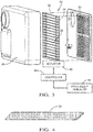
Figure 2 is a diagrammatic illustration showing selected features of a sensor device designed according to an embodiment of this invention. -
Figure 3 diagrammatically illustrates features of the sensor shown inFigure 2 in a partially exploded view. -
Figure 4 schematically illustrates an example reflector designed according to an embodiment of this invention. -
Figure 1 schematically illustrates adetector 20 on avehicle 22. Thedetector 20 is useful for detecting objects in a vicinity of thevehicle 22. While thedetector 20 may take various forms, for discussion purposes, thedetector 20 is considered a radar detector that utilizes known radar techniques. - The
detector 20 has a field of view schematically shown at 24. One characteristic of thedetector 20 is that the field ofview 24 is adjustable in a vertical direction as shown by thearrows 26. In the illustrated example embodiment, the field ofview 24 is dynamically adjustable to compensate for changes in the pitch angle of thevehicle 22, which is represented at 28 inFigure 1 . Adjusting the field ofview 24 provides angular compensation to offset vehicle pitch motion so that the field ofview 24 is directed along a desired trajectory from thedetector 22 without requiring an expanded vertical field. -
Figures 2 and3 illustrate selected features of an example embodiment of thedetector 20. Aradiation emitter 30 comprises a plurality of radar antenna elements in this example. A plurality ofreflectors 32 are situated in a near field region of theradiation emitter 30. The near field region is based, at least in part, on the wavelength of the radiation emitted by theradiation emitter 30. For example, the near field boundary is defined by 2∗D/λ, where D is the aperture diameter of the antenna and λ is the wavelength of the emitted radiation. The area between the near field boundary and theemitter 30 is the near field region and fits within a distance of approximately twice the wavelength from theemitter 30. For example, a long-range radar wavelength useful on thevehicle 22 of 76GHz has an associated near field region of approximately 8 millimeters. Thereflectors 32 are situated within that 8 millimeter space. - The
reflectors 32 have at least one characteristic that limits any phase shift of the emitted radiation reflected from thereflectors 32. In the illustrated example embodiment, there is no phase shift of the emitted radiation reflected from thereflectors 32. Avoiding or minimizing any phase shift avoids any requirement for further adaptations to compensate for such phase shift and maintains radar performance as expected from the design of theemitter 30. - In the illustrated example embodiment, the
reflectors 32 include a reflecting material on at least one surface. The reflecting material has an index of refraction that is less than 1. The reflecting material in some embodiments comprises a metal, such as gold, copper, or silver. Gold has a refractive index of about 0.3, copper has a refractive index of about 0.5, and silver has a refractive index of about 0.2. Utilizing a reflecting material with a refractive index less than 1 over the emitter wavelength bandpass avoids any phase change of the electrical field of the emitted radiation that is reflected from thereflectors 32. - The
reflectors 32 are also designed and situated relative to theradiation emitter 30 so that the angle of incidence of the emitted radiation approaching thereflectors 32 is larger than the critical angle of the reflecting material. As known, a critical angle of a reflecting material is determined by the arcsine of the refractive index of that material. Controlling the angle of incidence in this manner allows the electrical field and magnetic field of the emitted radiation to reflect from thereflectors 32 at an angle equal to the incidence angle with no phase change after penetrating the surface of the reflecting material for a small distance. The amount of penetration, as known, is based on the wavelength of the radiation, the resistivity of the reflecting material, and the relative permeability of the reflecting material. The penetration distance may be referred to as the skin depth of the reflecting material. - The skin depth of such reflecting materials may be determined in a known manner. The
reflectors 32 have a thickness that is at least five times the skin depth of the reflecting material such that when the angle of incidence is greater than the critical angle of the reflecting material the emitted radiation reflected from thereflectors 32 will effectively have no phase change relative to the electromagnetic field in the near field region of theradiation emitter 30. - For example,
reflectors 32 having gold reflecting material have an associated critical angle of 15.7 degrees. With a skin depth of about 1.7 microns and a minimum thickness of the reflecting material of 8.6 microns, thereflectors 32 do not introduce any undesired phase shift. Another example embodiment includes a copper reflecting material with a critical angle of 27.4 degrees, a skin depth of 1.5 microns and a thickness of 7.5 microns. Another example embodiment includes silver as the reflecting material having a critical angle of 8.6 degrees, a skin depth of 1.5 microns, and a thickness of 7.3 microns. Withsuch reflectors 32, the electromagnetic field of the radiation emitted by theradiation emitter 30, whose oscillations contain electric and magnetic fields that are perpendicular to each other, will not be phase shifted when reflected from thereflectors 32. - A supporting
structure 34 supports thereflectors 32 so that each of them has the same orientation relative to theradiation emitter 30. In the illustrated example, thereflectors 32 are situated as a plurality of louvers whose angular position relative to theradiation emitter 30 may be adjusted simultaneously to direct the radiation emitted from theradiation emitters 30 in a desired direction. - As schematically shown in
Figure 3 , anactuator 40 causes movement of at least one portion of thesupport structure 34 to change an orientation of thereflectors 32. Acontroller 42 is configured to control theactuator 40 to cause thereflectors 32 to be in a desired orientation relative to theradiation emitter 30 to direct radiation from thedetector 20 along a desired trajectory or in a desired direction. Thecontroller 42 is configured or suitably programmed to determine the orientation based upon, for example, a pitch angle of thevehicle 22.Figure 3 includes apitch angle indicator 44, which may be an accelerometer as an example, that provides an indication of the pitch angle of thevehicle 22. As thevehicle 22 travels over different terrain and the pitch angle of thevehicle 22 changes, thecontroller 42 dynamically causes the orientation of thereflectors 32 to change by controlling theactuator 40 to direct the field ofview 24 of thedetector 20 along a desired direction. In an example embodiment, thecontroller 42 is programmed or configured to determine the pitch angle from thepitch angle indicator 44, determine an amount of movement of thereflectors 32 needed to achieve a desired angle of reflection, and control theactuator 40 to cause such movement. Feedback circuitry in the actuator circuit provides closed loop control over the orientation of thereflectors 32. Depending on the configuration of theactuator 40, a capacitance of the actuator may provide feedback information regarding the orientation of thereflectors 32. - The
actuator 40, in an example embodiment, comprises a micro-electromechanical (MEM) actuator. Another example includes a microhydraulic electro-wetting actuator. Other example embodiments include adielectric elastomer actuator 40. Another example actuator comprises a voice coil motor. Such actuators allow for achieving the necessary amount of change in orientation of thereflectors 32 to address a variety of different pitch angles of thevehicle 22. At the same time, such actuators are capable of fitting within tight packaging constraints and contribute toward maintaining relatively low power requirements for achieving desired reflector orientations. Further, such actuators are capable or responding very quickly to driver circuitry of thecontroller 42 to achieve real-time, dynamic adjustment of the orientation of thereflectors 32 that tracks changes in the pitch angle of thevehicle 22. - The features of the
example detector 20 are also useful for setting an orientation of thereflectors 32 relative to theradiation emitter 30 during a manufacturing or installation process associated with mounting thedetector 20 on a particular vehicle. For example, the location or orientation of thedetector 20 will be different on some vehicles than others. Rather than requiring an entirely different sensor configuration for such differing vehicles, a single detectordesign including reflectors 32 is adjustable to achieve a desired direction of the field ofview 24. It may not be necessary to also provide dynamic adjustment on such vehicles while the vehicle is traveling but, of course, some such embodiments will include adaptive adjustment control. - In some example embodiments, the
reflectors 32 comprise solid pieces of the reflecting material. In other embodiments, as shown inFigure 4 , the reflectors 32' comprise a mesh of reflecting material. The reflector 32' inFigure 4 includes a grid mesh size selected based upon the wavelength of the radiation emitted by thedetector 20. For example, a grid mesh size that is two orders of magnitude smaller than the wavelength of the emitted radiation allows the reflection characteristic of the reflectors 32' to be the same as if they had solid reflecting surfaces. Considering a 76GHz radar detector configuration, an example reflector 32' includes a metal mesh with fibers or strands that are 60 microns thick with spacing between them that are 40 microns wide. Keeping the grid spacing in a range of 35 to 100 times smaller than the wavelength allows for a mesh reflecting surface to perform similarly to a solid surface without requiring a particular thickness of the mesh material. Smaller grid spacing further reduces the effect of the thickness of the mesh material. - The disclosed example features of a detector designed according to an embodiment of this invention provide a solution to addressing the need for achieving detector radiation direction at a variety of angles relative to a vehicle. Controlling the orientation of the
reflectors 32, 32' allows for dynamically adjusting the direction of the field ofview 24 of thedetector 20 to compensate for changes in the pitch angle of a vehicle. Additionally, changing the orientation of thereflectors 32 allows for accommodating different mounting orientations of adetector 20 on a vehicle during manufacturing or installation. Placing thereflectors 32 in the near field region and controlling their orientation allows for achieving a minimized vertical field while still having sufficient angular capability to address changes in vehicle pitch without introducing phase shift in the emitted radiation. - The preceding description is exemplary rather than limiting in nature. Variations and modifications to the disclosed examples may become apparent to those skilled in the art that do not necessarily depart from the essence of this invention. The scope of legal protection given to this invention can only be determined by studying the following claims.
Claims (15)
- A detector (20) for use on a vehicle (22), the detector (20) comprising:a radiation emitter (30) having a near field region that is defined at least in part by a wavelength of radiation emitted by the radiation emitter (30); anda radiation steering device includinga plurality of reflectors (32) situated to reflect the radiation emitted by the radiation emitter (30), the plurality of reflectors (32) being in the near field region, the plurality of reflectors (32) having at least one characteristic that limits any phase shift of the emitted radiation reflected from the reflectors (32);an actuator (40) configured to adjust an orientation of the plurality of reflectors (32); anda controller (42) configured to determine an orientation of the plurality of reflectors (32) relative to the radiation emitter (30) to steer the emitted radiation reflected from the reflectors (32) in a determined direction, the controller (42) being configured to control the actuator (40) to achieve the determined orientation.
- The detector (20) of claim 1, wherein
the at least one characteristic of the plurality of reflectors (32) comprises an index of refraction of a reflecting material of the reflectors (32); and
the index of refraction is less than 1. - The detector (20) of claim 2, wherein
the at least one characteristic of the plurality of reflectors (32) comprises a thickness of the reflecting material; and
the thickness is greater than a skin depth corresponding to a distance that the emitted radiation penetrates the reflecting material. - The detector (20) of claim 3, wherein the thickness is at least 5 times greater than the skin depth.
- The detector (20) of claim 3, wherein
the reflecting material has a critical angle based on the index of refraction; and
the controller (42) is configured to determine the orientation of the plurality of reflectors (32) relative to the radiation emitter (30) such than an angle of incidence of the emitted radiation approaching the reflectors (32) is larger than the critical angle. - The detector (20) of claim 1, wherein
the plurality of reflectors (32) comprise a reflecting material; and
the reflecting material comprises a mesh and/or at least one of gold, copper or silver. - The detector (20) of claim 1, wherein
the detector (20) is supported on a vehicle (22);
the controller (42) is configured to receive an indication of a pitch angle of the vehicle (22); and
the controller (42) determines the orientation of the plurality of reflectors (32) based on the pitch angle of the vehicle (22). - The detector (20) of claim 9, wherein the controller (42) is configured to control the actuator (40) to dynamically adjust the orientation of the plurality of reflectors (32) based on changes in the pitch angle of the vehicle (22).
- The detector (20) of claim 1, wherein
the plurality of reflectors (32) comprises a plurality of moveable louvers; and
the actuator (40) adjusts the orientation the plurality of moveable louvers simultaneously. - A method of directing radiation emitted by a detector (20) having a near field region that is defined at least in part by a wavelength of radiation emitted by the detector (20), the method comprising:determining a direction for the radiation; andadjusting an orientation of a plurality of reflectors (32) to steer the radiation emitted by the detector (20) and reflected from the reflectors (32) in the determined direction, wherein the plurality of reflectors (32) are in the near field region and the plurality of reflectors (32) have at least one characteristic that limits any phase shift of the emitted radiation reflected from the reflectors (32).
- The method of claim 10, wherein
the detector (20) is supported on a vehicle (22); and
the method comprisesdetermining a pitch angle of the vehicle (22); anddetermining the orientation of the plurality of reflectors (32) based on the pitch angle of the vehicle (22). - The method of claim 11, comprising dynamically adjusting the orientation of the plurality of reflectors (32) based on changes in the pitch angle of the vehicle (22).
- The method of claim 10, wherein
the at least one characteristic of the plurality of reflectors (32) comprises an index of refraction of a reflecting material of the reflectors (32); and
the index of refraction is less than 1. - The method of claim 13, wherein
the at least one characteristic of the plurality of reflectors (32) comprises a thickness of the reflecting material;
the thickness is greater than a skin depth corresponding to a distance that the emitted radiation penetrates the reflecting material; and
the distance that the emitted radiation penetrates the reflecting material is based on the wavelength of the emitted radiation, a resistivity of the reflecting material and a relative permeability of the reflecting material. - The method of claim 13, wherein
the reflecting material has a critical angle based on the index of refraction; and
the controller (42) is configured to determine the orientation of the plurality of reflectors (32) relative to the radiation emitter (30) such than an angle of incidence of the emitted radiation approaching the reflectors (32) is larger than the critical angle.
Applications Claiming Priority (1)
| Application Number | Priority Date | Filing Date | Title |
|---|---|---|---|
| US16/151,859 US11264706B2 (en) | 2018-10-04 | 2018-10-04 | Object sensor including pitch compensation |
Publications (2)
| Publication Number | Publication Date |
|---|---|
| EP3633403A1 true EP3633403A1 (en) | 2020-04-08 |
| EP3633403B1 EP3633403B1 (en) | 2023-12-13 |
Family
ID=68051650
Family Applications (1)
| Application Number | Title | Priority Date | Filing Date |
|---|---|---|---|
| EP19198839.3A Active EP3633403B1 (en) | 2018-10-04 | 2019-09-23 | Object sensor including pitch compensation |
Country Status (3)
| Country | Link |
|---|---|
| US (1) | US11264706B2 (en) |
| EP (1) | EP3633403B1 (en) |
| CN (1) | CN111007513B (en) |
Families Citing this family (1)
| Publication number | Priority date | Publication date | Assignee | Title |
|---|---|---|---|---|
| JP7720273B2 (en) * | 2022-03-07 | 2025-08-07 | 株式会社ニフコ | Sensor Bracket |
Citations (3)
| Publication number | Priority date | Publication date | Assignee | Title |
|---|---|---|---|---|
| US20120019432A1 (en) * | 2010-07-26 | 2012-01-26 | Searete Llc, A Limited Liability Corporation Of The State Of Delaware | Metamaterial surfaces |
| US20180081038A1 (en) * | 2016-09-21 | 2018-03-22 | Innoviz Technologies Ltd. | Methods Circuits Devices Assemblies Systems and Functionally Associated Machine Executable Code for Light Detection and Ranging Based Scanning |
| WO2018055513A2 (en) * | 2016-09-20 | 2018-03-29 | Innoviz Technologies Ltd. | Methods circuits devices assemblies systems and functionally associated machine executable code for light detection and ranging based scanning |
Family Cites Families (6)
| Publication number | Priority date | Publication date | Assignee | Title |
|---|---|---|---|---|
| CN1215475A (en) * | 1996-03-29 | 1999-04-28 | 株式会社小松制作所 | Vehicle Speed Detection System |
| DE10065024A1 (en) * | 2000-12-23 | 2002-07-04 | Bosch Gmbh Robert | Device for adjusting the main beam direction of a radar sensor |
| DE102009009227B4 (en) * | 2008-02-21 | 2021-10-07 | Adc Automotive Distance Control Systems Gmbh | Method for the automatic alignment of a radiation sensor in a vehicle |
| WO2015122095A1 (en) * | 2014-02-13 | 2015-08-20 | コニカミノルタ株式会社 | Mirror unit, distance measuring device, and laser radar, and mobile body and fixed object having these |
| US20170102704A1 (en) * | 2015-10-13 | 2017-04-13 | Delphi Technologies, Inc. | Automated Vehicle Object Detection Device With Level Detection |
| US10281564B2 (en) * | 2016-06-29 | 2019-05-07 | Aptiv Technologies Limited | Refractive beam steering device useful for automated vehicle LIDAR |
-
2018
- 2018-10-04 US US16/151,859 patent/US11264706B2/en active Active
-
2019
- 2019-09-23 EP EP19198839.3A patent/EP3633403B1/en active Active
- 2019-09-26 CN CN201910916552.XA patent/CN111007513B/en active Active
Patent Citations (3)
| Publication number | Priority date | Publication date | Assignee | Title |
|---|---|---|---|---|
| US20120019432A1 (en) * | 2010-07-26 | 2012-01-26 | Searete Llc, A Limited Liability Corporation Of The State Of Delaware | Metamaterial surfaces |
| WO2018055513A2 (en) * | 2016-09-20 | 2018-03-29 | Innoviz Technologies Ltd. | Methods circuits devices assemblies systems and functionally associated machine executable code for light detection and ranging based scanning |
| US20180081038A1 (en) * | 2016-09-21 | 2018-03-22 | Innoviz Technologies Ltd. | Methods Circuits Devices Assemblies Systems and Functionally Associated Machine Executable Code for Light Detection and Ranging Based Scanning |
Also Published As
| Publication number | Publication date |
|---|---|
| US11264706B2 (en) | 2022-03-01 |
| CN111007513A (en) | 2020-04-14 |
| CN111007513B (en) | 2024-03-15 |
| EP3633403B1 (en) | 2023-12-13 |
| US20200112085A1 (en) | 2020-04-09 |
Similar Documents
| Publication | Publication Date | Title |
|---|---|---|
| EP0840140B1 (en) | Antenna apparatus | |
| US5926127A (en) | Motor vehicle radar system | |
| CN109959912B (en) | Multi-facet MEMS mirror device for vehicle LIDAR | |
| CN104094133B (en) | Radar sensor unit with adjustable mirror | |
| EP3279684B1 (en) | Refractive beam steering device useful for automated vehicle lidar | |
| CN107843887B (en) | Position Feedback Sensing for Automated Vehicle LiDAR | |
| US10840580B2 (en) | Dynamically adjusted antenna system and antenna array included therein | |
| EP3650887B1 (en) | Mems mirror with extended field of view useful for vehicle lidar | |
| CN112601976A (en) | Apparatus and method for providing driver assistance for a vehicle | |
| KR102172071B1 (en) | Method of capturing the surrounding area of a car by object classification, control device, driver assistance system, and car | |
| EP3633403B1 (en) | Object sensor including pitch compensation | |
| CN113263980A (en) | Deformable mirror | |
| EP3889639A1 (en) | Ranging sensor, vehicle lamp, and ranging method | |
| US20110199252A1 (en) | Sensor device having a variable azimuthal detection range for a motor vehicle | |
| KR101733039B1 (en) | Method for operating beam of seeker for guided air vehicle | |
| JP2001235537A (en) | Alignment judgment system for directional radar antenna | |
| NL9300113A (en) | Radar device. | |
| KR20250005360A (en) | Method for detecting deposits on a radome and for open-loop and/or closed-loop controlling at least one heating element of the radome, computing device, computer-readable (storage) medium and temperature-controllable radar sensor system | |
| JP2015190810A (en) | Radar device and radar method | |
| US20230266456A1 (en) | Systems and methods of target detection | |
| JP2007240369A (en) | Radio wave axis adjusting apparatus and radio wave axis adjusting method | |
| EP4431983A1 (en) | Detecting module, and lamp device and lamp system provided with detecting module | |
| US20200319303A1 (en) | Beam distribution adjustment for a sensor | |
| US12292501B2 (en) | Cover device for reducing refraction of radar radio waves | |
| JP2019138636A (en) | Object detection device and object detection system |
Legal Events
| Date | Code | Title | Description |
|---|---|---|---|
| PUAI | Public reference made under article 153(3) epc to a published international application that has entered the european phase |
Free format text: ORIGINAL CODE: 0009012 |
|
| STAA | Information on the status of an ep patent application or granted ep patent |
Free format text: STATUS: THE APPLICATION HAS BEEN PUBLISHED |
|
| AK | Designated contracting states |
Kind code of ref document: A1 Designated state(s): AL AT BE BG CH CY CZ DE DK EE ES FI FR GB GR HR HU IE IS IT LI LT LU LV MC MK MT NL NO PL PT RO RS SE SI SK SM TR |
|
| AX | Request for extension of the european patent |
Extension state: BA ME |
|
| STAA | Information on the status of an ep patent application or granted ep patent |
Free format text: STATUS: REQUEST FOR EXAMINATION WAS MADE |
|
| 17P | Request for examination filed |
Effective date: 20201008 |
|
| RBV | Designated contracting states (corrected) |
Designated state(s): AL AT BE BG CH CY CZ DE DK EE ES FI FR GB GR HR HU IE IS IT LI LT LU LV MC MK MT NL NO PL PT RO RS SE SI SK SM TR |
|
| STAA | Information on the status of an ep patent application or granted ep patent |
Free format text: STATUS: EXAMINATION IS IN PROGRESS |
|
| 17Q | First examination report despatched |
Effective date: 20220321 |
|
| RAP3 | Party data changed (applicant data changed or rights of an application transferred) |
Owner name: APTIV TECHNOLOGIES LIMITED |
|
| GRAP | Despatch of communication of intention to grant a patent |
Free format text: ORIGINAL CODE: EPIDOSNIGR1 |
|
| STAA | Information on the status of an ep patent application or granted ep patent |
Free format text: STATUS: GRANT OF PATENT IS INTENDED |
|
| INTG | Intention to grant announced |
Effective date: 20230629 |
|
| GRAS | Grant fee paid |
Free format text: ORIGINAL CODE: EPIDOSNIGR3 |
|
| GRAA | (expected) grant |
Free format text: ORIGINAL CODE: 0009210 |
|
| STAA | Information on the status of an ep patent application or granted ep patent |
Free format text: STATUS: THE PATENT HAS BEEN GRANTED |
|
| P01 | Opt-out of the competence of the unified patent court (upc) registered |
Effective date: 20231025 |
|
| AK | Designated contracting states |
Kind code of ref document: B1 Designated state(s): AL AT BE BG CH CY CZ DE DK EE ES FI FR GB GR HR HU IE IS IT LI LT LU LV MC MK MT NL NO PL PT RO RS SE SI SK SM TR |
|
| REG | Reference to a national code |
Ref country code: GB Ref legal event code: FG4D |
|
| REG | Reference to a national code |
Ref country code: CH Ref legal event code: EP |
|
| REG | Reference to a national code |
Ref country code: DE Ref legal event code: R096 Ref document number: 602019043139 Country of ref document: DE |
|
| REG | Reference to a national code |
Ref country code: IE Ref legal event code: FG4D |
|
| PG25 | Lapsed in a contracting state [announced via postgrant information from national office to epo] |
Ref country code: GR Free format text: LAPSE BECAUSE OF FAILURE TO SUBMIT A TRANSLATION OF THE DESCRIPTION OR TO PAY THE FEE WITHIN THE PRESCRIBED TIME-LIMIT Effective date: 20240314 |
|
| REG | Reference to a national code |
Ref country code: LT Ref legal event code: MG9D |
|
| PG25 | Lapsed in a contracting state [announced via postgrant information from national office to epo] |
Ref country code: LT Free format text: LAPSE BECAUSE OF FAILURE TO SUBMIT A TRANSLATION OF THE DESCRIPTION OR TO PAY THE FEE WITHIN THE PRESCRIBED TIME-LIMIT Effective date: 20231213 |
|
| REG | Reference to a national code |
Ref country code: NL Ref legal event code: MP Effective date: 20231213 |
|
| PG25 | Lapsed in a contracting state [announced via postgrant information from national office to epo] |
Ref country code: ES Free format text: LAPSE BECAUSE OF FAILURE TO SUBMIT A TRANSLATION OF THE DESCRIPTION OR TO PAY THE FEE WITHIN THE PRESCRIBED TIME-LIMIT Effective date: 20231213 |
|
| PG25 | Lapsed in a contracting state [announced via postgrant information from national office to epo] |
Ref country code: LT Free format text: LAPSE BECAUSE OF FAILURE TO SUBMIT A TRANSLATION OF THE DESCRIPTION OR TO PAY THE FEE WITHIN THE PRESCRIBED TIME-LIMIT Effective date: 20231213 Ref country code: GR Free format text: LAPSE BECAUSE OF FAILURE TO SUBMIT A TRANSLATION OF THE DESCRIPTION OR TO PAY THE FEE WITHIN THE PRESCRIBED TIME-LIMIT Effective date: 20240314 Ref country code: ES Free format text: LAPSE BECAUSE OF FAILURE TO SUBMIT A TRANSLATION OF THE DESCRIPTION OR TO PAY THE FEE WITHIN THE PRESCRIBED TIME-LIMIT Effective date: 20231213 Ref country code: BG Free format text: LAPSE BECAUSE OF FAILURE TO SUBMIT A TRANSLATION OF THE DESCRIPTION OR TO PAY THE FEE WITHIN THE PRESCRIBED TIME-LIMIT Effective date: 20240313 |
|
| REG | Reference to a national code |
Ref country code: AT Ref legal event code: MK05 Ref document number: 1640890 Country of ref document: AT Kind code of ref document: T Effective date: 20231213 |
|
| PG25 | Lapsed in a contracting state [announced via postgrant information from national office to epo] |
Ref country code: NL Free format text: LAPSE BECAUSE OF FAILURE TO SUBMIT A TRANSLATION OF THE DESCRIPTION OR TO PAY THE FEE WITHIN THE PRESCRIBED TIME-LIMIT Effective date: 20231213 |
|
| PG25 | Lapsed in a contracting state [announced via postgrant information from national office to epo] |
Ref country code: SE Free format text: LAPSE BECAUSE OF FAILURE TO SUBMIT A TRANSLATION OF THE DESCRIPTION OR TO PAY THE FEE WITHIN THE PRESCRIBED TIME-LIMIT Effective date: 20231213 Ref country code: RS Free format text: LAPSE BECAUSE OF FAILURE TO SUBMIT A TRANSLATION OF THE DESCRIPTION OR TO PAY THE FEE WITHIN THE PRESCRIBED TIME-LIMIT Effective date: 20231213 Ref country code: NO Free format text: LAPSE BECAUSE OF FAILURE TO SUBMIT A TRANSLATION OF THE DESCRIPTION OR TO PAY THE FEE WITHIN THE PRESCRIBED TIME-LIMIT Effective date: 20240313 Ref country code: NL Free format text: LAPSE BECAUSE OF FAILURE TO SUBMIT A TRANSLATION OF THE DESCRIPTION OR TO PAY THE FEE WITHIN THE PRESCRIBED TIME-LIMIT Effective date: 20231213 Ref country code: LV Free format text: LAPSE BECAUSE OF FAILURE TO SUBMIT A TRANSLATION OF THE DESCRIPTION OR TO PAY THE FEE WITHIN THE PRESCRIBED TIME-LIMIT Effective date: 20231213 Ref country code: HR Free format text: LAPSE BECAUSE OF FAILURE TO SUBMIT A TRANSLATION OF THE DESCRIPTION OR TO PAY THE FEE WITHIN THE PRESCRIBED TIME-LIMIT Effective date: 20231213 |
|
| PG25 | Lapsed in a contracting state [announced via postgrant information from national office to epo] |
Ref country code: IS Free format text: LAPSE BECAUSE OF FAILURE TO SUBMIT A TRANSLATION OF THE DESCRIPTION OR TO PAY THE FEE WITHIN THE PRESCRIBED TIME-LIMIT Effective date: 20240413 |
|
| PG25 | Lapsed in a contracting state [announced via postgrant information from national office to epo] |
Ref country code: AT Free format text: LAPSE BECAUSE OF FAILURE TO SUBMIT A TRANSLATION OF THE DESCRIPTION OR TO PAY THE FEE WITHIN THE PRESCRIBED TIME-LIMIT Effective date: 20231213 Ref country code: CZ Free format text: LAPSE BECAUSE OF FAILURE TO SUBMIT A TRANSLATION OF THE DESCRIPTION OR TO PAY THE FEE WITHIN THE PRESCRIBED TIME-LIMIT Effective date: 20231213 |
|
| PG25 | Lapsed in a contracting state [announced via postgrant information from national office to epo] |
Ref country code: SK Free format text: LAPSE BECAUSE OF FAILURE TO SUBMIT A TRANSLATION OF THE DESCRIPTION OR TO PAY THE FEE WITHIN THE PRESCRIBED TIME-LIMIT Effective date: 20231213 |
|
| PG25 | Lapsed in a contracting state [announced via postgrant information from national office to epo] |
Ref country code: SM Free format text: LAPSE BECAUSE OF FAILURE TO SUBMIT A TRANSLATION OF THE DESCRIPTION OR TO PAY THE FEE WITHIN THE PRESCRIBED TIME-LIMIT Effective date: 20231213 Ref country code: SK Free format text: LAPSE BECAUSE OF FAILURE TO SUBMIT A TRANSLATION OF THE DESCRIPTION OR TO PAY THE FEE WITHIN THE PRESCRIBED TIME-LIMIT Effective date: 20231213 Ref country code: RO Free format text: LAPSE BECAUSE OF FAILURE TO SUBMIT A TRANSLATION OF THE DESCRIPTION OR TO PAY THE FEE WITHIN THE PRESCRIBED TIME-LIMIT Effective date: 20231213 Ref country code: IT Free format text: LAPSE BECAUSE OF FAILURE TO SUBMIT A TRANSLATION OF THE DESCRIPTION OR TO PAY THE FEE WITHIN THE PRESCRIBED TIME-LIMIT Effective date: 20231213 Ref country code: IS Free format text: LAPSE BECAUSE OF FAILURE TO SUBMIT A TRANSLATION OF THE DESCRIPTION OR TO PAY THE FEE WITHIN THE PRESCRIBED TIME-LIMIT Effective date: 20240413 Ref country code: EE Free format text: LAPSE BECAUSE OF FAILURE TO SUBMIT A TRANSLATION OF THE DESCRIPTION OR TO PAY THE FEE WITHIN THE PRESCRIBED TIME-LIMIT Effective date: 20231213 Ref country code: CZ Free format text: LAPSE BECAUSE OF FAILURE TO SUBMIT A TRANSLATION OF THE DESCRIPTION OR TO PAY THE FEE WITHIN THE PRESCRIBED TIME-LIMIT Effective date: 20231213 Ref country code: AT Free format text: LAPSE BECAUSE OF FAILURE TO SUBMIT A TRANSLATION OF THE DESCRIPTION OR TO PAY THE FEE WITHIN THE PRESCRIBED TIME-LIMIT Effective date: 20231213 |
|
| PG25 | Lapsed in a contracting state [announced via postgrant information from national office to epo] |
Ref country code: PL Free format text: LAPSE BECAUSE OF FAILURE TO SUBMIT A TRANSLATION OF THE DESCRIPTION OR TO PAY THE FEE WITHIN THE PRESCRIBED TIME-LIMIT Effective date: 20231213 Ref country code: PT Free format text: LAPSE BECAUSE OF FAILURE TO SUBMIT A TRANSLATION OF THE DESCRIPTION OR TO PAY THE FEE WITHIN THE PRESCRIBED TIME-LIMIT Effective date: 20240415 |
|
| PG25 | Lapsed in a contracting state [announced via postgrant information from national office to epo] |
Ref country code: PT Free format text: LAPSE BECAUSE OF FAILURE TO SUBMIT A TRANSLATION OF THE DESCRIPTION OR TO PAY THE FEE WITHIN THE PRESCRIBED TIME-LIMIT Effective date: 20240415 Ref country code: PL Free format text: LAPSE BECAUSE OF FAILURE TO SUBMIT A TRANSLATION OF THE DESCRIPTION OR TO PAY THE FEE WITHIN THE PRESCRIBED TIME-LIMIT Effective date: 20231213 |
|
| REG | Reference to a national code |
Ref country code: DE Ref legal event code: R097 Ref document number: 602019043139 Country of ref document: DE |
|
| PG25 | Lapsed in a contracting state [announced via postgrant information from national office to epo] |
Ref country code: DK Free format text: LAPSE BECAUSE OF FAILURE TO SUBMIT A TRANSLATION OF THE DESCRIPTION OR TO PAY THE FEE WITHIN THE PRESCRIBED TIME-LIMIT Effective date: 20231213 |
|
| PLBE | No opposition filed within time limit |
Free format text: ORIGINAL CODE: 0009261 |
|
| STAA | Information on the status of an ep patent application or granted ep patent |
Free format text: STATUS: NO OPPOSITION FILED WITHIN TIME LIMIT |
|
| PG25 | Lapsed in a contracting state [announced via postgrant information from national office to epo] |
Ref country code: SI Free format text: LAPSE BECAUSE OF FAILURE TO SUBMIT A TRANSLATION OF THE DESCRIPTION OR TO PAY THE FEE WITHIN THE PRESCRIBED TIME-LIMIT Effective date: 20231213 |
|
| PG25 | Lapsed in a contracting state [announced via postgrant information from national office to epo] |
Ref country code: SI Free format text: LAPSE BECAUSE OF FAILURE TO SUBMIT A TRANSLATION OF THE DESCRIPTION OR TO PAY THE FEE WITHIN THE PRESCRIBED TIME-LIMIT Effective date: 20231213 Ref country code: DK Free format text: LAPSE BECAUSE OF FAILURE TO SUBMIT A TRANSLATION OF THE DESCRIPTION OR TO PAY THE FEE WITHIN THE PRESCRIBED TIME-LIMIT Effective date: 20231213 |
|
| 26N | No opposition filed |
Effective date: 20240916 |
|
| PG25 | Lapsed in a contracting state [announced via postgrant information from national office to epo] |
Ref country code: MC Free format text: LAPSE BECAUSE OF FAILURE TO SUBMIT A TRANSLATION OF THE DESCRIPTION OR TO PAY THE FEE WITHIN THE PRESCRIBED TIME-LIMIT Effective date: 20231213 |
|
| REG | Reference to a national code |
Ref country code: DE Ref legal event code: R081 Ref document number: 602019043139 Country of ref document: DE Owner name: APTIV TECHNOLOGIES AG, CH Free format text: FORMER OWNER: APTIV TECHNOLOGIES LIMITED, ST. MICHAEL, BB Ref country code: CH Ref legal event code: PL |
|
| PG25 | Lapsed in a contracting state [announced via postgrant information from national office to epo] |
Ref country code: LU Free format text: LAPSE BECAUSE OF NON-PAYMENT OF DUE FEES Effective date: 20240923 |
|
| REG | Reference to a national code |
Ref country code: BE Ref legal event code: MM Effective date: 20240930 |
|
| PG25 | Lapsed in a contracting state [announced via postgrant information from national office to epo] |
Ref country code: BE Free format text: LAPSE BECAUSE OF NON-PAYMENT OF DUE FEES Effective date: 20240930 |
|
| PG25 | Lapsed in a contracting state [announced via postgrant information from national office to epo] |
Ref country code: CH Free format text: LAPSE BECAUSE OF NON-PAYMENT OF DUE FEES Effective date: 20240930 |
|
| PG25 | Lapsed in a contracting state [announced via postgrant information from national office to epo] |
Ref country code: IE Free format text: LAPSE BECAUSE OF NON-PAYMENT OF DUE FEES Effective date: 20240923 |
|
| PG25 | Lapsed in a contracting state [announced via postgrant information from national office to epo] |
Ref country code: FI Free format text: LAPSE BECAUSE OF FAILURE TO SUBMIT A TRANSLATION OF THE DESCRIPTION OR TO PAY THE FEE WITHIN THE PRESCRIBED TIME-LIMIT Effective date: 20231213 |
|
| PGFP | Annual fee paid to national office [announced via postgrant information from national office to epo] |
Ref country code: DE Payment date: 20250814 Year of fee payment: 7 |
|
| PGFP | Annual fee paid to national office [announced via postgrant information from national office to epo] |
Ref country code: GB Payment date: 20250924 Year of fee payment: 7 |
|
| PGFP | Annual fee paid to national office [announced via postgrant information from national office to epo] |
Ref country code: FR Payment date: 20250908 Year of fee payment: 7 |
|
| PG25 | Lapsed in a contracting state [announced via postgrant information from national office to epo] |
Ref country code: CY Free format text: LAPSE BECAUSE OF FAILURE TO SUBMIT A TRANSLATION OF THE DESCRIPTION OR TO PAY THE FEE WITHIN THE PRESCRIBED TIME-LIMIT; INVALID AB INITIO Effective date: 20190923 |
|
| PG25 | Lapsed in a contracting state [announced via postgrant information from national office to epo] |
Ref country code: HU Free format text: LAPSE BECAUSE OF FAILURE TO SUBMIT A TRANSLATION OF THE DESCRIPTION OR TO PAY THE FEE WITHIN THE PRESCRIBED TIME-LIMIT; INVALID AB INITIO Effective date: 20190923 |