EP3633356A2 - Composite structure bondline inspection - Google Patents
Composite structure bondline inspection Download PDFInfo
- Publication number
- EP3633356A2 EP3633356A2 EP19196436.0A EP19196436A EP3633356A2 EP 3633356 A2 EP3633356 A2 EP 3633356A2 EP 19196436 A EP19196436 A EP 19196436A EP 3633356 A2 EP3633356 A2 EP 3633356A2
- Authority
- EP
- European Patent Office
- Prior art keywords
- ray
- objective lens
- light
- composite structure
- inspection system
- Prior art date
- Legal status (The legal status is an assumption and is not a legal conclusion. Google has not performed a legal analysis and makes no representation as to the accuracy of the status listed.)
- Granted
Links
Images



Classifications
-
- G—PHYSICS
- G01—MEASURING; TESTING
- G01N—INVESTIGATING OR ANALYSING MATERIALS BY DETERMINING THEIR CHEMICAL OR PHYSICAL PROPERTIES
- G01N23/00—Investigating or analysing materials by the use of wave or particle radiation, e.g. X-rays or neutrons, not covered by groups G01N3/00 – G01N17/00, G01N21/00 or G01N22/00
- G01N23/02—Investigating or analysing materials by the use of wave or particle radiation, e.g. X-rays or neutrons, not covered by groups G01N3/00 – G01N17/00, G01N21/00 or G01N22/00 by transmitting the radiation through the material
- G01N23/06—Investigating or analysing materials by the use of wave or particle radiation, e.g. X-rays or neutrons, not covered by groups G01N3/00 – G01N17/00, G01N21/00 or G01N22/00 by transmitting the radiation through the material and measuring the absorption
- G01N23/18—Investigating the presence of flaws defects or foreign matter
-
- G—PHYSICS
- G01—MEASURING; TESTING
- G01N—INVESTIGATING OR ANALYSING MATERIALS BY DETERMINING THEIR CHEMICAL OR PHYSICAL PROPERTIES
- G01N23/00—Investigating or analysing materials by the use of wave or particle radiation, e.g. X-rays or neutrons, not covered by groups G01N3/00 – G01N17/00, G01N21/00 or G01N22/00
- G01N23/02—Investigating or analysing materials by the use of wave or particle radiation, e.g. X-rays or neutrons, not covered by groups G01N3/00 – G01N17/00, G01N21/00 or G01N22/00 by transmitting the radiation through the material
- G01N23/06—Investigating or analysing materials by the use of wave or particle radiation, e.g. X-rays or neutrons, not covered by groups G01N3/00 – G01N17/00, G01N21/00 or G01N22/00 by transmitting the radiation through the material and measuring the absorption
- G01N23/083—Investigating or analysing materials by the use of wave or particle radiation, e.g. X-rays or neutrons, not covered by groups G01N3/00 – G01N17/00, G01N21/00 or G01N22/00 by transmitting the radiation through the material and measuring the absorption the radiation being X-rays
-
- G—PHYSICS
- G01—MEASURING; TESTING
- G01N—INVESTIGATING OR ANALYSING MATERIALS BY DETERMINING THEIR CHEMICAL OR PHYSICAL PROPERTIES
- G01N21/00—Investigating or analysing materials by the use of optical means, i.e. using sub-millimetre waves, infrared, visible or ultraviolet light
- G01N21/84—Systems specially adapted for particular applications
- G01N21/88—Investigating the presence of flaws or contamination
- G01N21/8806—Specially adapted optical and illumination features
-
- G—PHYSICS
- G01—MEASURING; TESTING
- G01N—INVESTIGATING OR ANALYSING MATERIALS BY DETERMINING THEIR CHEMICAL OR PHYSICAL PROPERTIES
- G01N23/00—Investigating or analysing materials by the use of wave or particle radiation, e.g. X-rays or neutrons, not covered by groups G01N3/00 – G01N17/00, G01N21/00 or G01N22/00
- G01N23/02—Investigating or analysing materials by the use of wave or particle radiation, e.g. X-rays or neutrons, not covered by groups G01N3/00 – G01N17/00, G01N21/00 or G01N22/00 by transmitting the radiation through the material
- G01N23/04—Investigating or analysing materials by the use of wave or particle radiation, e.g. X-rays or neutrons, not covered by groups G01N3/00 – G01N17/00, G01N21/00 or G01N22/00 by transmitting the radiation through the material and forming images of the material
-
- G—PHYSICS
- G01—MEASURING; TESTING
- G01T—MEASUREMENT OF NUCLEAR OR X-RADIATION
- G01T1/00—Measuring X-radiation, gamma radiation, corpuscular radiation, or cosmic radiation
- G01T1/16—Measuring radiation intensity
- G01T1/20—Measuring radiation intensity with scintillation detectors
-
- G—PHYSICS
- G01—MEASURING; TESTING
- G01T—MEASUREMENT OF NUCLEAR OR X-RADIATION
- G01T1/00—Measuring X-radiation, gamma radiation, corpuscular radiation, or cosmic radiation
- G01T1/16—Measuring radiation intensity
- G01T1/20—Measuring radiation intensity with scintillation detectors
- G01T1/2002—Optical details, e.g. reflecting or diffusing layers
-
- G—PHYSICS
- G01—MEASURING; TESTING
- G01N—INVESTIGATING OR ANALYSING MATERIALS BY DETERMINING THEIR CHEMICAL OR PHYSICAL PROPERTIES
- G01N2223/00—Investigating materials by wave or particle radiation
- G01N2223/03—Investigating materials by wave or particle radiation by transmission
-
- G—PHYSICS
- G01—MEASURING; TESTING
- G01N—INVESTIGATING OR ANALYSING MATERIALS BY DETERMINING THEIR CHEMICAL OR PHYSICAL PROPERTIES
- G01N2223/00—Investigating materials by wave or particle radiation
- G01N2223/10—Different kinds of radiation or particles
- G01N2223/101—Different kinds of radiation or particles electromagnetic radiation
- G01N2223/1016—X-ray
-
- G—PHYSICS
- G01—MEASURING; TESTING
- G01N—INVESTIGATING OR ANALYSING MATERIALS BY DETERMINING THEIR CHEMICAL OR PHYSICAL PROPERTIES
- G01N2223/00—Investigating materials by wave or particle radiation
- G01N2223/30—Accessories, mechanical or electrical features
-
- G—PHYSICS
- G01—MEASURING; TESTING
- G01N—INVESTIGATING OR ANALYSING MATERIALS BY DETERMINING THEIR CHEMICAL OR PHYSICAL PROPERTIES
- G01N2223/00—Investigating materials by wave or particle radiation
- G01N2223/50—Detectors
- G01N2223/505—Detectors scintillation
-
- G—PHYSICS
- G01—MEASURING; TESTING
- G01N—INVESTIGATING OR ANALYSING MATERIALS BY DETERMINING THEIR CHEMICAL OR PHYSICAL PROPERTIES
- G01N2223/00—Investigating materials by wave or particle radiation
- G01N2223/60—Specific applications or type of materials
- G01N2223/615—Specific applications or type of materials composite materials, multilayer laminates
-
- G—PHYSICS
- G01—MEASURING; TESTING
- G01N—INVESTIGATING OR ANALYSING MATERIALS BY DETERMINING THEIR CHEMICAL OR PHYSICAL PROPERTIES
- G01N2223/00—Investigating materials by wave or particle radiation
- G01N2223/60—Specific applications or type of materials
- G01N2223/629—Specific applications or type of materials welds, bonds, sealing compounds
-
- G—PHYSICS
- G01—MEASURING; TESTING
- G01N—INVESTIGATING OR ANALYSING MATERIALS BY DETERMINING THEIR CHEMICAL OR PHYSICAL PROPERTIES
- G01N2223/00—Investigating materials by wave or particle radiation
- G01N2223/60—Specific applications or type of materials
- G01N2223/646—Specific applications or type of materials flaws, defects
- G01N2223/6462—Specific applications or type of materials flaws, defects microdefects
Definitions
- the present disclosure relates generally to inspecting composite structures and, more specifically, to inspecting a bondline in a composite structure. More particularly, the present disclosure relates to a method and apparatus for inspecting a bondline in a composite structure using X-rays.
- composite bond strength is not quantifiable using conventional non-destructive techniques.
- the inconsistencies in the bondline may be difficult to detect visually or by using non-destructive testing.
- Some types of inconsistencies in the bondline of a composite structure such as microporosity, crystallization, and kissing disbonds, may not be currently detectable using non-destructive inspection techniques.
- the non-destructive testing of the bondline may be at least one of undesirably time-consuming or undesirably costly. Therefore, it would be desirable to have a method and apparatus that take into account at least some of the issues discussed above, as well as other possible issues.
- the present disclosure provides an X-ray inspection system.
- the X-ray inspection system comprises an X-ray source, an X-ray scintillator, a light detector, a first objective lens, and a second objective lens.
- the first objective lens is positioned between the X-ray scintillator and the light detector.
- the second objective lens is positioned between the first objective lens and the light detector.
- the present disclosure also provides a bondline inspection system.
- the bondline inspection system comprises an X-ray source assembly, an X-ray detection assembly, and an alignment system.
- the X-ray detection assembly comprises an X-ray scintillator, at least two objective lenses, and a light detector.
- the alignment system is physically associated with both the X-ray source assembly and the X-ray detection assembly.
- the present disclosure also provides a method of inspecting a bondline within a composite structure.
- X-rays are sent into a first surface of the composite structure.
- X-rays are received at an X-ray scintillator from a second surface of the composite structure.
- Light is generated from the X-rays received at the X-ray scintillator.
- the light generated from the X-rays received at the X-ray scintillator is magnified by a first objective lens to form magnified light.
- the magnified light is directed to a light detector using a second objective lens. Whether the bondline has a desired quality is determined using an output from the light detector.
- the present disclosure recognizes and take into account one or more different considerations. For example, the present disclosure recognizes and takes into account that conventional non-destructive techniques, such as high frequency ultrasound, do not determine small variations in the bondline due to undesirable curing.
- a laser bond inspection device may be used to determine bondline integrity.
- a laser bond inspection device may also undesirably break the bondline during the laser bond inspection process.
- the only way to test bondline integrity is by means of a pull test, which is destructive.
- bondlines in composite structures may be formed using fasteners, co-curing composite portions, bonding the composite portions by curing a bonding adhesive, or by other desirable methods.
- Fasteners may be used as reinforcement for the bondlines of the composite structures.
- Fasteners may be used as a failsafe for the composite structures having the bondlines. The fasteners are used as a failsafe because conventional inspection techniques do not provide strength measurements of the bondline.
- the present disclosure recognizes and takes into account that the fasteners add to a weight of an aircraft. Removing the fasteners will reduce the weight of the aircraft and improve weight-dependent performance features of the aircraft.
- the the present disclosure additionally recognize and take into account that providing non-destructive inspection for the bondline may allow for bondlines without failsafe fasteners.
- the present disclosure recognizes and takes into account that conventional X-ray inspection is undesirable for detecting microporosity and other types of inconsistencies in bondlines in composite structures.
- Conventional X-ray inspection has undesirably low resolution.
- characteristics of X-ray inspection include a number of pixels of a detector and a flux of X-rays from the X-ray source. Increasing the size of the detector without changing the number of pixels reduces the resolution of the inspection. Increasing the number of pixels without increasing the flex of X-rays, the contrast of the data from the detector is reduced.
- microchannel plates are used in X-ray inspection to amplify signals.
- Environmental light undesirably affects the microchannel plates.
- Environmental light may effectively disable the microchannel plates.
- X-ray scintillators receive X-rays and generate visible light.
- X-ray scintillators include structured scintillators and powder scintillators.
- Powder scintillators include powder having different orientations. Powder scintillators scatter light due to the powder orientation.
- structured scintillators having material in an ordered structure scatters less light than powder scintillators.
- Structured scintillators are formed of crystals. Structured scintillators may also be referred to as crystal scintillators. Structured scintillators having material in an ordered structure scatter less light than powder scintillators.
- CMOS complementary metal-oxide-semiconductor
- the present disclosure recognizes and takesinto account that geometrical distortion is created in x-ray imaging. Geometrical distortion increases the difficulty of detecting inconsistencies in the bondline of a composite structure. The the present disclosure recognizes and takes into account that it would be desirable to reduce aberration and geometrical distortion in x-ray inspection of composite structures.
- optical systems comprise different lens types. Different lens types perform different functions. For example, relay lenses are used to invert an image or extend the length of a system. As another example, an objective lens, or a series of objective lenses, is used to focus light. An objective lens can be used to reduce or eliminate distortion.
- the present disclosure provides an X-ray inspection system.
- the X-ray inspection system comprises an X-ray source, an X-ray scintillator, a light detector, and at least two objective lenses.
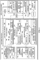
- X-ray inspection system 100 is present in inspection environment 102 .
- X-ray inspection system 100 may be used to inspect composite structure 104 .
- the X-ray inspection system 100 may be referred to as bondline inspection system 105 .
- X-ray inspection system 100 comprises X-ray source 106 , X-ray scintillator 108 , light detector 110 , first objective lens 112 , and second objective lens 114 .
- First objective lens 112 is positioned between X-ray scintillator 108 and light detector 110 .
- Second objective lens 114 is positioned between first objective lens 112 and light detector 110 .
- First objective lens 112 is positioned such that first objective lens 112 is first distance 116 from X-ray scintillator 108 .
- First distance 116 is selected such that first objective lens 112 provides magnification 118 .
- the first distance 116 may be adjustable.
- First objective lens 112 has a diameter sufficient to receive all of light 124 emitted by X-ray scintillator 108 .
- First objective lens 112 is large enough to focus and collimate light 124 from X-ray scintillator 108 .
- First objective lens 112 has anti-reflective coating 120 configured to selectively block light having wavelengths 122 of light 124 emitted by X-ray scintillator 108 .
- Wavelengths 122 emitted by X-ray scintillator 108 is in a specific window. Wavelengths 122 emitted by X-ray scintillator 108 may be described as high frequency. Wavelengths 122 emitted by X-ray scintillator 108 may be described as in the green region of visible light.
- Anti-reflective coating 120 is selected to selectively block light having wavelengths 122 .
- Anti-reflective coating 120 reduces or prevents light being reflected from first objective lens 112 back to X-ray scintillator 108 .
- the anti-reflective coating 120 can reduce noise in X-ray inspection system 100 .
- the anti-reflective coating 120 preferably reduces exterior light from outside of X-ray inspection system 100 .
- Anti-reflective coating 120 reduces or prevents ghost images in X-ray scintillator 108 .
- Second objective lens 114 has anti-reflective coating 126 configured to selectively block light having wavelengths 122 of light 124 emitted by X-ray scintillator 108 .
- Anti-reflective coating 126 is selected to selectively block light having wavelengths 122 .
- Anti-reflective coating 126 reduces or prevents light being reflected from second objective lens 114 back to X-ray scintillator 108 .
- the anti-reflective coating 126 preferably reduces noise in X-ray inspection system 100 .
- the anti-reflective coating 126 preferably reduces exterior light from outside of X-ray inspection system 100 .
- Anti-reflective coating 126 reduces or prevents ghost images in X-ray scintillator 108 .
- First objective lens 112 and second objective lens 114 are configured to receive, magnify, and direct light 124 generated from X-rays 156 received at X-ray scintillator 108 .
- First objective lens 112 and second objective lens 114 together focus light 124 onto a smaller area than the surface area of X-ray scintillator 108 .
- First objective lens 112 magnifies light 124 received from X-ray scintillator 108 to form magnified light 128 .
- Second objective lens 114 receives and compacts magnified light 128 .
- Second objective lens 114 is configured to provide compaction 130 of magnified light 128 .
- Compaction 130 of magnified light 128 provides improved image quality.
- Compaction 130 of magnified light 128 provides a reduction in distortion.
- Second objective lens 114 reduces or eliminates negative effects of first objective lens 112 on light 124 .
- second objective lens 114 reduces or eliminates pincushion, barrel distortion, horizontal non-linearity and vertical non linearity to provide improved image quality.
- Second objective lens 114 compacts and directs magnified light 128 to form compacted light 132 directed to light detector 110 .
- Light detector 110 comprises one of charge-coupled device (CCD) image detector 134 or complementary metal-oxide-semiconductor (CMOS) image detector 136 .
- Light detector 110 has pitch 138 of at least 20 microns, where a micron is a millionth of a meter. Pitch 138 is a measured distance from one pixel to another pixel of light detector 110 .
- X-ray source 106 is preferably positioned within X-ray source housing 140 .
- X-ray source assembly 142 includes X-ray source housing 140 and X-ray source 106 .
- X-ray scintillator 108 , light detector 110 , first objective lens 112 , and second objective lens 114 are preferably positioned within detector housing 144 .
- X-ray detection assembly 146 includes detector housing 144 and components within detector housing 144 .
- X-ray source assembly 142 is positioned relative to first surface 150 of composite structure 104 .
- X-ray source assembly 142 is positioned such that X-ray source 106 faces first surface 150 .
- the X-ray source assembly 142 can be positioned such that X-ray source housing 140 is in contact with first surface 150 .
- X-ray detection assembly 146 is positioned relative to second surface 152 of composite structure 104 .
- Second surface 152 is an opposite surface of first surface 150 about bondline 148 of composite structure 104 .
- the second surface 152 may be described as being on a second side of composite structure 104 .
- X-ray detection assembly 146 is positioned such that X-ray scintillator 108 is positioned between light detector 110 and second surface 152 .
- the X-ray detection assembly 146 can be positioned such that detector housing 144 is in contact with second surface 152 .
- X-ray source 106 directs X-rays 154 into first surface 150 of composite structure 104 .
- the first surface 150 may be described as being on a first side of composite structure 104 .
- X-ray source 106 takes any desirable form.
- X-ray source 106 is preferably a macro X-ray source.
- the x-ray source 106 preferably comprises micro focus tubes. When x-ray source 106 comprises at least one micro focus tube, resolution can be increased for an image produced by light detector 110 .
- Micro focus tubes generate very small focal spot sizes, typically below 50 ⁇ m in diameter.
- the X-ray source 106 is preferably a micro-focused X-ray tube.
- X-ray scintillator 108 receives X-rays 156 that traveled through first surface 150 , bondline 148 , and second surface 152 . X-ray scintillator 108 generates light 124 from X-rays 156 received.
- X-ray scintillator 108 is preferably a structured scintillator 158 .
- Structured scintillator 158 is formed of crystals growing in a structured format.
- First objective lens 112 receives light 124 and forms magnified light 128 .
- Magnified light 128 is received by second objective lens 114 .
- Second objective lens 114 forms compacted light 132 from magnified light 128 .
- Light detector 110 receives compacted light 132 and forms output 160 .
- Output 160 is sent to computer 162 .
- a determination is made using output 160 whether bondline 148 has a desired quality.
- the output 160 may be referred to as sensor data.
- An image formed using output 160 can be displayed on display 163 of computer 162 .
- the determination is can be performed based on information displayed on display 163 .
- the determination can also be performed based on an image on display 163 .
- Inconsistencies 164 in bondline 148 can be identified. Inconsistencies 164 include any type of inconsistency present in bondline 148 . Inconsistencies 164 may comprise microporosity. Inconsistencies 164 may comprise crystallization. Inconsistencies 164 may comprise a kissing disbond.
- X-ray detection assembly 146 is configured to maximize the flux collected. X-ray detection assembly 146 is configured to receive and process X-rays 156 to minimize loss of X-rays 156 . For example, X-ray detection assembly 146 is sized to collect substantially all X-rays 156 exiting second surface 152 . X-ray detection assembly 146 includes structured scintillator 158 rather than a powder scintillator to reduce loss of X-rays 156 during generation of light 124 .
- X-ray detection assembly 146 is aligned relative to X-ray source assembly 142 .
- X-ray inspection system 100 has alignment system 166 .
- Alignment system 166 takes any desirable form. Alignment system 166 is configured to align X-ray source assembly 142 and X-ray detection assembly 146 relative to each other.
- Alignment system 166 can take the form of magnetic alignment system 168 .
- first component 170 of magnetic alignment system 168 is connected to X-ray source housing 140
- second component 172 of magnetic alignment system 168 is connected to detector housing 144 .
- alignment system 166 takes the form of magnetic alignment system 168
- one of X-ray source housing 140 or detector housing 144 may be moved by magnetic force of magnetic alignment system 168 when the other of X-ray source housing 140 or detector housing 144 is moved.
- a magnetic force of magnetic alignment system 168 enables alignment of X-ray source assembly 142 and X-ray detection assembly 146 .
- Alignment of X-ray source assembly 142 relative to X-ray detection assembly 146 affects collection of X-rays 156 . If X-ray source assembly 142 and X-ray detection assembly 146 are offset, X-ray detection assembly 146 will collect only a portion of X-rays 156 .
- alignment system 166 When alignment system 166 takes the form of magnetic alignment system 168 , X-ray inspection system 100 may be maneuvered by an operator. When alignment system 166 takes the form of magnetic alignment system 168 , automated movement of X-ray inspection system 100 may be simplified. For example, when alignment system 166 takes the form of magnetic alignment system 168 , X-ray source assembly 142 may be maneuvered by an automated system while X-ray detection assembly 146 is moved by magnetic attraction of magnetic alignment system 168 .
- alignment system 166 comprises one of magnetic alignment system 168 or fiducial alignment system 174 .
- Alignment system 166 can be a combination of magnetic alignment system 168 and fiducial alignment system 174 .
- fiducial alignment system 174 may be used to initially position X-ray source assembly 142 and X-ray detection assembly 146 relative to composite structure 104 .
- magnetic alignment system 168 may be used to precisely position X-ray source assembly 142 and X-ray detection assembly 146 relative to each other.
- Alignment system 166 can take the form of fiducial alignment system 174 .
- fiducial alignment system 174 fiducials 176 are located on or near composite structure 104 for alignment of X-ray inspection system 100 .
- alignment system 166 takes the form of fiducial alignment system 174
- X-ray inspection system 100 is maneuvered by controller 178 .
- Controller 178 is configured to position X-ray detection assembly 146 relative to X-ray source assembly 142 . Controller 178 is configured to position light detector 110 relative to X-ray source 106 . Controller 178 may be implemented in at least one of hardware or software. Controller 178 may be a processor unit in a computer system or a specialist circuit depending on the particular implementation.
- Bondline inspection system 105 comprises X-ray source assembly 142 , X-ray detection assembly 146 , and alignment system 166 .
- X-ray detection assembly 146 comprises X-ray scintillator 108 , at least two objective lenses, and light detector 110 .
- Alignment system 166 is physically associated with both X-ray source assembly 142 and X-ray detection assembly 146 .
- Including at least two objective lenses reduces or eliminates chromatic aberrations.
- the at least two objective lenses are positioned within X-ray detection assembly 146 to magnify and compact light 124 from X-ray scintillator 108 .
- any desirable quantity of objective lenses may be present in bondline inspection system 105 . More than two objective lenses can be present in bondline inspection system 105 .
- Bondline inspection system 105 can have three objective lenses, four objective lenses, or more than four objective lenses. Increasing a quantity of objective lenses within X-ray detection assembly 146 increases the magnification provided within X-ray detection assembly 146 . Increasing a quantity of objective lenses also increases the complexity of X-ray detection assembly 146 .
- a quantity of objective lenses in x-ray detection assembly 146 may be selected based on a desired image quality for inspecting bondline 148 for small porosity, voids, or other small inconsistencies.
- X-ray inspection system 100 is configured to provide inspection for qualification of composite structure 104 with bondline 148 .
- X-ray inspection system 100 is configured to send X-rays 154 into a surface area of between 2.54 to 12.7 cm (one to five inches) of first surface 150 .
- X-ray inspection system 100 is configured to provide inspection for composite structure 104 with bondline 148 having a thickness of 0.24 to 0.64 cm (0.1 to 0.25 inches).
- inspection environment 102 in Figure 1 is not meant to imply physical or architectural limitations to the manner in which the present disclosure may be implemented.
- Other components in addition to, or in place of, the ones illustrated may be used. Some components may be unnecessary.
- the blocks are presented to illustrate some functional components. One or more of these blocks may be combined, divided, or combined and divided into different blocks when implemented in the present disclosure.
- alignment system 166 may take any desirable form.
- alignment system 166 may take the form of a laser tracking alignment system.
- x-ray inspection system 100 comprises a third objective lens.
- the third objective lens is positioned between second objective lens 114 and light detector 110 .
- x-ray inspection system 100 further comprises a fourth objective lens between the third objective lens and light detector 110 .
- X-ray inspection system 200 is a physical implementation of X-ray inspection system 100 of Figure 1 .
- X-ray inspection system 200 comprises X-ray source assembly 202 and X-ray detection assembly 204 .
- X-ray source assembly 202 is a physical implementation of X-ray source assembly 142 of Figure 1 .
- X-ray source assembly 202 is positioned relative to first surface 206 of composite structure 208 .
- X-ray source assembly 202 is configured to send X-rays (not depicted) into first surface 206 of composite structure 208 .
- An X-ray source (not depicted) is present within housing 209 of X-ray source assembly 202 .
- X-ray detection assembly 204 is a physical implementation of X-ray detection assembly 146 of Figure 1 .
- X-ray detection assembly 204 is positioned relative to second surface 210 of composite structure 208 .
- X-ray detection assembly 204 receives X-rays (not depicted) that travel through composite structure 208 .
- An X-ray scintillator (not depicted), at least two objective lenses (not depicted), and a light detector (not depicted) are present inside of detector housing 212 of X-ray detection assembly 204 .
- X-ray detection assembly 204 is in electronic communication with computer system 214 .
- image 218 is created from output of the light detector of X-ray detection assembly 204 .
- Image 218 may be used to determine if inconsistencies are present in bondline 222 .
- Image 218 may be used to determine if a desired quality is present for bondline 222 .
- inconsistencies 220 are present in bondline 222 of composite structure 208 .
- X-ray source assembly 202 and X-ray detection assembly 204 are positioned to inspect portion 224 of bondline 222 having inconsistencies 220 .
- Inconsistencies 220 are visible in image 218 .
- X-ray inspection system 300 is a physical implementation of X-ray inspection system 100 of Figure 1 .
- X-ray inspection system 300 comprises X-ray source 302 , X-ray scintillator 304 , light detector 306 , first objective lens 308 , and second objective lens 310 .
- First objective lens 308 is positioned between X-ray scintillator 304 and light detector 306 .
- Second objective lens 310 is positioned between first objective lens 308 and light detector 306 .
- View 312 is a simplified view of X-ray inspection system 100 of Figure 1 .
- X-ray inspection system 100 may further comprise other components, such as at least a number of housings, a controller, an alignment system, or any other desirable components.
- X-ray source 302 directs X-rays 314 into first surface 316 of composite structure 318 .
- X-rays 314 enter composite structure 318 and travel through composite structure 318 .
- X-ray scintillator 304 receives X-rays 320 exiting composite structure 318 at second surface 322 .
- X-ray scintillator 304 receives X-rays 320 and generates light 324 .
- First objective lens 308 magnifies light 324 generated from X-rays 320 received at X-ray scintillator 304 .
- Second objective lens 310 concentrates the magnified light from first objective lens 308 .
- Second objective lens 310 directs compacted light to light detector 306 .
- Output (not depicted) of light detector 306 is used to determine if a desired quality is present in bondline 326 of composite structure 318 .
- X-ray inspection system 300 provides images with sufficient resolution to detect inconsistencies within bondline 326 of composite structure 318 .
- X-ray inspection system 300 is configured to provide sufficient resolution and sufficient contrast to detect kissing disbonds, microporosity, crystallization, or other types of inconsistencies within bondline 326 .
- distances between components are set to provide sufficient magnification and collect substantially all of the X-rays and maximize the collection of the generated light.
- a ratio of distance 328 between X-ray source 302 and sample 330 and distance 332 between sample 330 and X-ray scintillator 304 is selected to provide a desired magnification.
- X-ray inspection system 300 may include more than two objective lenses.
- x-ray inspection system 300 comprises a third objective lens.
- the third objective lens is positioned between second objective lens 310 and light detector 306 .
- x-ray inspection system 300 further comprises a fourth objective lens between the third objective lens and light detector 306 .
- FIG. 2-3 The different components shown in Figures 2-3 may be combined with components in Figure 1 , used with components in Figure 1 , or a combination of the two. Additionally, some of the components in Figures 2-3 may be illustrative examples of how components shown in block form in Figure 1 may be implemented as physical structures.
- Method 400 is a method of inspecting bondline 148 within composite structure 104 of Figure 1 .
- Method 400 may be performed using X-ray inspection system 100 of Figure 1 .
- Method 400 may be used to inspect bondline 222 within composite structure 208 of Figure 2 .
- Method 400 may be performed using X-ray inspection system 200 of Figure 2 .
- Method 400 may be used to inspect bondline 326 within composite structure 318 of Figure 3 .
- Method 400 may be performed using X-ray inspection system 300 of Figure 3 .
- Method 400 sends X-rays into a first surface of a composite structure (operation 402 ).
- Method 400 receives X-rays at an X-ray scintillator from a second surface of the composite structure (operation 404 ).
- Method 400 generates light from the X-rays received at the X-ray scintillator (operation 406 ).
- Method 400 magnifies the light generated from the X-rays received at the X-ray scintillator by a first objective lens to form magnified light (operation 408 ).
- Method 400 directs the magnified light to a light detector using a second objective lens (operation 410 ).
- Method 400 determines if the bondline has a desired quality using an output from the light detector (operation 412 ). Afterwards, method 400 terminates.
- the method 400 may position an X-ray source housing relative to the first surface of the composite structure prior to sending the X-rays into the first surface of the composite structure using an X-ray source positioned within the X-ray source housing (operation 414 ).
- the method 400 may further comprise positioning a detector housing relative to the second surface of the composite structure prior to sending the X-rays into the first surface of the composite structure, wherein the X-ray scintillator, the light detector, the first objective lens, and the second objective lens are positioned within the detector housing (operation 416 ).
- the method 400 may further comprise positioning the detector housing relative to the second surface of the composite structure comprises aligning the detector housing relative to the X-ray source housing (operation 418 ).
- the method 400 may further comprise sending X-rays into the first surface of the composite structure comprises sending X-rays into a portion of the composite structure having a surface area in the range of 2.54 to 12.7 cm (one to five inches), with a bondline thickness of 0.24 to 0.64 cm (0.1 to 0.25 inches) (operation 420 ).
- each block in the flowcharts or block diagrams may represent a module, a segment, a function, and/or a portion of an operation or step.
- the function or functions noted in the blocks may occur out of the order noted in the figures. For example, in some cases, two blocks shown in succession may be executed substantially concurrently, or the blocks may sometimes be performed in the reverse order, depending upon the functionality involved. Also, other blocks may be added, in addition to the illustrated blocks, in a flowchart or block diagram. Some blocks may be optional. For example, in method 400 , operations 414 through 420 may be optional.
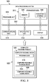
- Data processing system 500 may be used to implement at least one of computer 162 or controller 178 of Figure 1 .
- the data processing system 500 may include communications fabric 502 .
- Communications fabric 502 provides communications between processor unit 504 , memory 506 , persistent storage 508 , communications unit 510 , input/output (I/O) unit 512 , and display 514 .
- Memory 506 , persistent storage 508 , communications unit 510 , input/output (I/O) unit 512 , and display 514 are examples of resources accessible by processor unit 504 via communications fabric 502 .
- Processor unit 504 serves to run instructions for software that may be loaded into memory 506 .
- Processor unit 504 may be a number of processors, a multi-processor core, or some other type of processor, depending on the particular implementation. Further, processor unit 504 may be implemented using a number of heterogeneous processor systems in which a main processor is present with secondary processors on a single chip. Processor unit 504 may be a symmetric multi-processor system containing multiple processors of the same type.
- Memory 506 and persistent storage 508 are examples of storage devices 516.
- a storage device is any piece of hardware that is capable of storing information, such as, for example, without limitation, data, program code in functional form, and other suitable information either on a temporary basis or a permanent basis.
- Storage devices 516 also may be referred to as computer readable storage devices in these examples.
- Memory 506 may be, for example, a random access memory or any other suitable volatile or non-volatile storage device.
- Persistent storage 508 may take various forms, depending on the particular implementation.
- Persistent storage 508 may contain one or more components or devices.
- persistent storage 508 may be a hard drive, a flash memory, a rewritable optical disk, a rewritable magnetic tape, or some combination of the above.
- the media used by persistent storage 508 also may be removable.
- a removable hard drive may be used for persistent storage 508 .
- Communications unit 510 may provide for communications with other data processing systems or devices.
- Communications unit 510 can be a network interface card.
- Communications unit 510 may provide communications through the use of either or both physical and wireless communications links.
- Input/output (I/O) unit 512 allows for input and output of data with other devices that may be connected to data processing system 500 .
- input/output (I/O) unit 512 may provide a connection for user input through a keyboard, a mouse, and/or some other suitable input device. Further, input/output (I/O) unit 512 may send output to a printer.
- Display 514 provides a mechanism to display information to a user.
- Instructions for the operating system, applications, and/or programs may be located in storage devices 516 , which are in communication with processor unit 504 through communications fabric 502 .
- the instructions can be in a functional form on persistent storage 508 . These instructions may be loaded into memory 506 for execution by processor unit 504 .
- the processes of the different embodiments may be performed by processor unit 504 using computer-implemented instructions, which may be located in a memory, such as memory 506 .
- program instructions are referred to as program instructions, program code, computer usable program code, or computer readable program code that may be read and executed by a processor in processor unit 504 .
- the program code in the different embodiments may be embodied on different physical or computer readable storage media, such as memory 506 or persistent storage 508 .
- Program code 518 is located in a functional form on computer readable media 520 that is selectively removable and may be loaded onto or transferred to data processing system 500 for execution by processor unit 504 .
- Program code 518 and computer readable media 520 can form computer program product 522 .
- the , computer readable media 520 may be computer readable storage media 524 or computer readable signal media 526 .
- Computer readable storage media 524 may include, for example, an optical or magnetic disk that is inserted or placed into a drive or other device that is part of persistent storage 508 for transfer onto a storage device, such as a hard drive, that is part of persistent storage 508 .
- Computer readable storage media 524 also may take the form of a persistent storage, such as a hard drive, a thumb drive, or a flash memory, that is connected to data processing system 500 . In some instances, computer readable storage media 524 may not be removable from data processing system 500 .
- Computer readable storage media 524 can be a physical or tangible storage device used to store program code 518 rather than a medium that propagates or transmits program code 518 .
- Computer readable storage media 524 is also referred to as a computer readable tangible storage device or a computer readable physical storage device. In other words, computer readable storage media 524 is a media that can be touched by a person.
- program code 518 may be transferred to data processing system 500 using computer readable signal media 526 .
- Computer readable signal media 526 may be, for example, a propagated data signal containing program code 518 .
- Computer readable signal media 526 may be an electromagnetic signal, an optical signal, and/or any other suitable type of signal. These signals may be transmitted over communications links, such as wireless communications links, optical fiber cable, coaxial cable, a wire, and/or any other suitable type of communications link. In other words, the communications link and/or the connection may be physical or wireless.
- the program code 518 may be downloaded over a network to persistent storage 508 from another device or data processing system through computer readable signal media 526 for use within data processing system 500 .
- program code stored in a computer readable storage medium in a server data processing system may be downloaded over a network from the server to data processing system 500 .
- the data processing system providing program code 518 may be a server computer, a client computer, or some other device capable of storing and transmitting program code 518 .
- data processing system 500 may include organic components integrated with inorganic components and/or may be comprised entirely of organic components excluding a human being.
- a storage device may be comprised of an organic semiconductor.
- the processor unit 504 may take the form of a hardware unit that has circuits that are manufactured or configured for a particular use. This type of hardware may perform operations without needing program code to be loaded into a memory from a storage device to be configured to perform the operations.
- processor unit 504 when processor unit 504 takes the form of a hardware unit, processor unit 504 may be a circuit system, an application specific integrated circuit (ASIC), a programmable logic device, or some other suitable type of hardware configured to perform a number of operations.
- ASIC application specific integrated circuit
- a programmable logic device the device is configured to perform the number of operations. The device may be reconfigured at a later time or may be permanently configured to perform the number of operations.
- Examples of programmable logic devices include, for example, a programmable logic array, a programmable array logic, a field programmable logic array, a field programmable gate array, and other suitable hardware devices.
- program code 518 may be omitted, because the processes for the different embodiments are implemented in a hardware unit.
- the processor unit 504 may be implemented using a combination of processors found in computers and hardware units.
- Processor unit 504 may have a number of hardware units and a number of processors that are configured to run program code 518 .
- some of the processes may be implemented in the number of hardware units, while other processes may be implemented in the number of processors.
- a a bus system may be used to implement communications fabric 502 and may be comprised of one or more buses, such as a system bus or an input/output bus.
- the bus system may be implemented using any suitable type of architecture that provides for a transfer of data between different components or devices attached to the bus system.
- communications unit 510 may include a number of devices that transmit data, receive data, or both transmit and receive data.
- Communications unit 510 may be, for example, a modem or a network adapter, two network adapters, or some combination thereof.
- a memory may be, for example, memory 506 , or a cache, such as that found in an interface and memory controller hub that may be present in communications fabric 502 .
- aircraft manufacturing and service method 600 may be described in the context of aircraft manufacturing and service method 600 as shown in Figure 6 and aircraft 700 as shown in Figure 7 .
- Figure 6 an illustration of an aircraft manufacturing and service method is depicted in accordance with the present disclosure.
- aircraft manufacturing and service method 600 may include specification and design 602 of aircraft 700 in Figure 7 and material procurement 604 .
- aircraft 700 During production, component and subassembly manufacturing 606 and system integration 608 of aircraft 700 takes place. Thereafter, aircraft 700 may go through certification and delivery 610 in order to be placed in service 612 . While in service 612 by a customer, aircraft 700 is scheduled for routine maintenance and service 614 , which may include modification, reconfiguration, refurbishment, or other maintenance and service.
- Each of the processes of aircraft manufacturing and service method 600 may be performed or carried out by a system integrator, a third party, and/or an operator.
- the operator may be a customer.
- a system integrator may include, without limitation, any number of aircraft manufacturers and major-system subcontractors
- a third party may include, without limitation, any number of vendors, subcontractors, and suppliers
- an operator may be an airline, a leasing company, a military entity, a service organization, and so on.
- aircraft 700 is produced by aircraft manufacturing and service method 600 of Figure 6 and may include airframe 702 with plurality of systems 704 and interior 706 .
- systems 704 include one or more of propulsion system 708 , electrical system 710 , hydraulic system 712 , and environmental system 714 . Any number of other systems may be included.
- propulsion system 708 the propulsion system 708
- electrical system 710 the electrical system 710
- hydraulic system 712 the hydraulic system
- environmental system 714 any number of other systems may be included.
- an aerospace example is shown, the present disclosure may be applied to other industries, such as the automotive industry.
- Apparatuses and methods embodied herein may be employed during at least one of the stages of aircraft manufacturing and service method 600 .
- the phrase "at least one of,” when used with a list of items, means different combinations of one or more of the listed items may be used, and only one of each item in the list may be needed.
- "at least one of' means any combination of items and number of items may be used from the list, but not all of the items in the list are required.
- the item may be a particular object, a thing, or a category.
- “at least one of item A, item B, or item C” may include, without limitation, item A, item A and item B, or item B. This example also may include item A, item B, and item C, or item B and item C. Of course, any combination of these items may be present. In other examples, "at least one of' may be, for example, without limitation, two of item A, one of item B, and ten of item C; four of item B and seven of item C; or other suitable combinations.
- X-ray inspection system 100 of Figure 1 may be used during component and subassembly manufacturing 606 to inspect composite structure 104 of Figure 1 .
- X-ray inspection system 100 may be used to inspect portions of aircraft 700 such as airframe 702 or portions of interior 706 .
- the present disclosure can provide an X-ray inspection system and methods for inspecting a composite structure.
- the present disclosure can provide a method to nondestructively verify bondline integrity of a bonded composite structure.
- the present disclosure may use phase contrast imaging in combination with microscopic imaging and high resolution nano-focus X-ray technology.
- the present disclosure may provide a system to conduct spot checks of bondline integrity by super high-resolution X-ray imaging and microscopy.
- the present disclosure can detect small anomalies and change in a bondline after curing, such as micro-porosity, crystallization, or kissing disbonds.
- the present disclosure can utilize nano-focus X-ray magnification and optical scintillation magnification.
- the X-ray inspection system of the present disclosure may be undesirably time-consuming for wide area inspection.
- the X-ray inspection system of the present disclosure may be used to create three-dimensional images. By means of stereo imaging, a three-dimensional image of bondline adhesive can be created. A three-dimensional image may be used to verify the bondline integrity. The three-dimensional image may be used to provide process control verification.
Landscapes
- Health & Medical Sciences (AREA)
- General Physics & Mathematics (AREA)
- Life Sciences & Earth Sciences (AREA)
- Physics & Mathematics (AREA)
- Immunology (AREA)
- Biochemistry (AREA)
- General Health & Medical Sciences (AREA)
- Analytical Chemistry (AREA)
- Chemical & Material Sciences (AREA)
- Pathology (AREA)
- High Energy & Nuclear Physics (AREA)
- Molecular Biology (AREA)
- Spectroscopy & Molecular Physics (AREA)
- Toxicology (AREA)
- Analysing Materials By The Use Of Radiation (AREA)
- Measurement Of Radiation (AREA)
Abstract
Description
- The present disclosure relates generally to inspecting composite structures and, more specifically, to inspecting a bondline in a composite structure. More particularly, the present disclosure relates to a method and apparatus for inspecting a bondline in a composite structure using X-rays.
- Currently, there are no methods to ensure accurate and reliable bond strength in composite manufacturing. Inconsistencies may be introduced into a bondline during manufacturing of a composite structure. The inconsistencies may lead to undesirably high re-work and scrap rates.
- Currently, composite bond strength is not quantifiable using conventional non-destructive techniques. The inconsistencies in the bondline may be difficult to detect visually or by using non-destructive testing. Some types of inconsistencies in the bondline of a composite structure, such as microporosity, crystallization, and kissing disbonds, may not be currently detectable using non-destructive inspection techniques. Further, the non-destructive testing of the bondline may be at least one of undesirably time-consuming or undesirably costly. Therefore, it would be desirable to have a method and apparatus that take into account at least some of the issues discussed above, as well as other possible issues.
- The present disclosure provides an X-ray inspection system. The X-ray inspection system comprises an X-ray source, an X-ray scintillator, a light detector, a first objective lens, and a second objective lens. The first objective lens is positioned between the X-ray scintillator and the light detector. The second objective lens is positioned between the first objective lens and the light detector.
- The present disclosure also provides a bondline inspection system. The bondline inspection system comprises an X-ray source assembly, an X-ray detection assembly, and an alignment system. The X-ray detection assembly comprises an X-ray scintillator, at least two objective lenses, and a light detector. The alignment system is physically associated with both the X-ray source assembly and the X-ray detection assembly.
- The present disclosure also provides a method of inspecting a bondline within a composite structure. X-rays are sent into a first surface of the composite structure. X-rays are received at an X-ray scintillator from a second surface of the composite structure. Light is generated from the X-rays received at the X-ray scintillator. The light generated from the X-rays received at the X-ray scintillator is magnified by a first objective lens to form magnified light. The magnified light is directed to a light detector using a second objective lens. Whether the bondline has a desired quality is determined using an output from the light detector.
- The present disclosure will now be detailed with reference to the following description and drawings.
-
-
Figure 1 is an illustration of a block diagram of an inspection environment in accordance with the present disclosure; -
Figure 2 is an illustration of an X-ray inspection system in accordance with the present disclosure; -
Figure 3 is an illustration of an X-ray inspection system in accordance with the present disclosure; -
Figure 4 is an illustration of a flowchart of a method for inspecting a bondline within a composite structure in accordance with the present disclosure; -
Figure 5 is an illustration of a data processing system in a form of a block diagram in accordance with the present disclosure; -
Figure 6 is an illustration of an aircraft manufacturing and service method in a form of a block diagram in accordance with the present disclosure; and -
Figure 7 is an illustration of an aircraft in a form of a block diagram in which the present disclosure may be implemented. - The present disclosure recognizes and take into account one or more different considerations. For example, the present disclosure recognizes and takes into account that conventional non-destructive techniques, such as high frequency ultrasound, do not determine small variations in the bondline due to undesirable curing. A laser bond inspection device (LBID) may be used to determine bondline integrity. However, a laser bond inspection device (LBID) may also undesirably break the bondline during the laser bond inspection process. Currently the only way to test bondline integrity is by means of a pull test, which is destructive.
- The present disclosure recognizes and takes into account that bondlines in composite structures may be formed using fasteners, co-curing composite portions, bonding the composite portions by curing a bonding adhesive, or by other desirable methods. Fasteners may be used as reinforcement for the bondlines of the composite structures. Fasteners may be used as a failsafe for the composite structures having the bondlines. The fasteners are used as a failsafe because conventional inspection techniques do not provide strength measurements of the bondline.
- The present disclosure recognizes and takes into account that the fasteners add to a weight of an aircraft. Removing the fasteners will reduce the weight of the aircraft and improve weight-dependent performance features of the aircraft. The the present disclosure additionally recognize and take into account that providing non-destructive inspection for the bondline may allow for bondlines without failsafe fasteners.
- The present disclosure recognizes and takes into account that conventional X-ray inspection is undesirable for detecting microporosity and other types of inconsistencies in bondlines in composite structures. Conventional X-ray inspection has undesirably low resolution.
- The present disclosure recognizes and take into account that characteristics of X-ray inspection include a number of pixels of a detector and a flux of X-rays from the X-ray source. Increasing the size of the detector without changing the number of pixels reduces the resolution of the inspection. Increasing the number of pixels without increasing the flex of X-rays, the contrast of the data from the detector is reduced.
- The present disclosure recognizes and takes into account that microchannel plates are used in X-ray inspection to amplify signals. Environmental light undesirably affects the microchannel plates. Environmental light may effectively disable the microchannel plates.
- The present disclosure recognizes and takes into account that X-ray scintillators receive X-rays and generate visible light. X-ray scintillators include structured scintillators and powder scintillators. Powder scintillators include powder having different orientations. Powder scintillators scatter light due to the powder orientation.
- The present disclosure recognizes and takes into account that structured scintillators having material in an ordered structure scatters less light than powder scintillators. Structured scintillators are formed of crystals. Structured scintillators may also be referred to as crystal scintillators. Structured scintillators having material in an ordered structure scatter less light than powder scintillators.
- The present disclosure recognizes and takes into account that X-ray complementary metal-oxide-semiconductor (CMOS) detectors are used in dental imaging and other small medical imaging. X-ray CMOS detectors may be undesirable in imaging larger areas. Inspecting large areas using X-ray CMOS detectors may take an undesirable amount of time.
- The present disclosure recognizes and takesinto account that geometrical distortion is created in x-ray imaging. Geometrical distortion increases the difficulty of detecting inconsistencies in the bondline of a composite structure. The the present disclosure recognizes and takes into account that it would be desirable to reduce aberration and geometrical distortion in x-ray inspection of composite structures.
- The present disclosure recognizes and takes into account that optical systems comprise different lens types. Different lens types perform different functions. For example, relay lenses are used to invert an image or extend the length of a system. As another example, an objective lens, or a series of objective lenses, is used to focus light. An objective lens can be used to reduce or eliminate distortion.
- The present disclosure provides an X-ray inspection system. The X-ray inspection system comprises an X-ray source, an X-ray scintillator, a light detector, and at least two objective lenses.
- Turning now to
Figure 1 , an illustration of a block diagram of an inspection environment is depicted in accordance with the present disclosure.X-ray inspection system 100 is present ininspection environment 102.X-ray inspection system 100 may be used to inspectcomposite structure 104. TheX-ray inspection system 100 may be referred to asbondline inspection system 105. -
X-ray inspection system 100 comprisesX-ray source 106,X-ray scintillator 108,light detector 110, firstobjective lens 112, and secondobjective lens 114. Firstobjective lens 112 is positioned betweenX-ray scintillator 108 andlight detector 110. Secondobjective lens 114 is positioned between firstobjective lens 112 andlight detector 110. - First
objective lens 112 is positioned such that firstobjective lens 112 isfirst distance 116 fromX-ray scintillator 108.First distance 116 is selected such that firstobjective lens 112 providesmagnification 118. Thefirst distance 116 may be adjustable. - First
objective lens 112 has a diameter sufficient to receive all of light 124 emitted byX-ray scintillator 108. Firstobjective lens 112 is large enough to focus and collimate light 124 fromX-ray scintillator 108. - First
objective lens 112 hasanti-reflective coating 120 configured to selectively blocklight having wavelengths 122 of light 124 emitted byX-ray scintillator 108.Wavelengths 122 emitted byX-ray scintillator 108 is in a specific window.Wavelengths 122 emitted byX-ray scintillator 108 may be described as high frequency.Wavelengths 122 emitted byX-ray scintillator 108 may be described as in the green region of visible light. -
Anti-reflective coating 120 is selected to selectively blocklight having wavelengths 122.Anti-reflective coating 120 reduces or prevents light being reflected from firstobjective lens 112 back toX-ray scintillator 108. Theanti-reflective coating 120 can reduce noise inX-ray inspection system 100. Theanti-reflective coating 120 preferably reduces exterior light from outside ofX-ray inspection system 100.Anti-reflective coating 120 reduces or prevents ghost images inX-ray scintillator 108. - Second
objective lens 114 hasanti-reflective coating 126 configured to selectively blocklight having wavelengths 122 of light 124 emitted byX-ray scintillator 108.Anti-reflective coating 126 is selected to selectively blocklight having wavelengths 122.Anti-reflective coating 126 reduces or prevents light being reflected from secondobjective lens 114 back toX-ray scintillator 108. Theanti-reflective coating 126 preferably reduces noise inX-ray inspection system 100. Theanti-reflective coating 126 preferably reduces exterior light from outside ofX-ray inspection system 100.Anti-reflective coating 126 reduces or prevents ghost images inX-ray scintillator 108. - First
objective lens 112 and secondobjective lens 114 are configured to receive, magnify, anddirect light 124 generated fromX-rays 156 received atX-ray scintillator 108. Firstobjective lens 112 and secondobjective lens 114 together focus light 124 onto a smaller area than the surface area ofX-ray scintillator 108. Firstobjective lens 112 magnifies light 124 received fromX-ray scintillator 108 to form magnifiedlight 128. Secondobjective lens 114 receives and compacts magnified light 128. - Second
objective lens 114 is configured to providecompaction 130 of magnifiedlight 128.Compaction 130 of magnified light 128 provides improved image quality.Compaction 130 of magnified light 128 provides a reduction in distortion. Secondobjective lens 114 reduces or eliminates negative effects of firstobjective lens 112 onlight 124. For example, secondobjective lens 114 reduces or eliminates pincushion, barrel distortion, horizontal non-linearity and vertical non linearity to provide improved image quality. Secondobjective lens 114 compacts and directs magnified light 128 to form compacted light 132 directed tolight detector 110. -
Light detector 110 comprises one of charge-coupled device (CCD)image detector 134 or complementary metal-oxide-semiconductor (CMOS) image detector 136.Light detector 110 haspitch 138 of at least 20 microns, where a micron is a millionth of a meter.Pitch 138 is a measured distance from one pixel to another pixel oflight detector 110. - X-ray
source 106 is preferably positioned withinX-ray source housing 140. X-raysource assembly 142 includesX-ray source housing 140 andX-ray source 106. -
X-ray scintillator 108,light detector 110, firstobjective lens 112, and secondobjective lens 114 are preferably positioned withindetector housing 144.X-ray detection assembly 146 includesdetector housing 144 and components withindetector housing 144. - To inspect
bondline 148 ofcomposite structure 104, X-raysource assembly 142 is positioned relative tofirst surface 150 ofcomposite structure 104. X-raysource assembly 142 is positioned such thatX-ray source 106 facesfirst surface 150. TheX-ray source assembly 142 can be positioned such thatX-ray source housing 140 is in contact withfirst surface 150. -
X-ray detection assembly 146 is positioned relative tosecond surface 152 ofcomposite structure 104.Second surface 152 is an opposite surface offirst surface 150 aboutbondline 148 ofcomposite structure 104. Thesecond surface 152 may be described as being on a second side ofcomposite structure 104. -
X-ray detection assembly 146 is positioned such thatX-ray scintillator 108 is positioned betweenlight detector 110 andsecond surface 152. TheX-ray detection assembly 146 can be positioned such thatdetector housing 144 is in contact withsecond surface 152. - To inspect
bondline 148,X-ray source 106 directsX-rays 154 intofirst surface 150 ofcomposite structure 104. Thefirst surface 150 may be described as being on a first side ofcomposite structure 104. - X-ray
source 106 takes any desirable form. X-raysource 106 is preferably a macro X-ray source. Thex-ray source 106 preferably comprises micro focus tubes. Whenx-ray source 106 comprises at least one micro focus tube, resolution can be increased for an image produced bylight detector 110. Micro focus tubes generate very small focal spot sizes, typically below 50 µm in diameter. TheX-ray source 106 is preferably a micro-focused X-ray tube. -
X-ray scintillator 108 receivesX-rays 156 that traveled throughfirst surface 150,bondline 148, andsecond surface 152.X-ray scintillator 108 generates light 124 fromX-rays 156 received. -
X-ray scintillator 108 is preferably astructured scintillator 158.Structured scintillator 158 is formed of crystals growing in a structured format. -
Light 124 travels to firstobjective lens 112. Firstobjective lens 112 receives light 124 and forms magnified light 128. Magnified light 128 is received by secondobjective lens 114. Secondobjective lens 114 forms compacted light 132 from magnifiedlight 128. -
Light detector 110 receives compactedlight 132 and formsoutput 160.Output 160 is sent tocomputer 162. A determination is made usingoutput 160 whetherbondline 148 has a desired quality. Theoutput 160 may be referred to as sensor data. An image formed usingoutput 160 can be displayed ondisplay 163 ofcomputer 162. The determination is can be performed based on information displayed ondisplay 163. The determination can also be performed based on an image ondisplay 163. -
Inconsistencies 164 inbondline 148 can be identified.Inconsistencies 164 include any type of inconsistency present inbondline 148.Inconsistencies 164 may comprise microporosity.Inconsistencies 164 may comprise crystallization.Inconsistencies 164 may comprise a kissing disbond. -
X-ray detection assembly 146 is configured to maximize the flux collected.X-ray detection assembly 146 is configured to receive andprocess X-rays 156 to minimize loss ofX-rays 156. For example,X-ray detection assembly 146 is sized to collect substantially allX-rays 156 exitingsecond surface 152.X-ray detection assembly 146 includes structuredscintillator 158 rather than a powder scintillator to reduce loss ofX-rays 156 during generation oflight 124. - To collect as much of
X-rays 156 exitingsecond surface 152 as possible,X-ray detection assembly 146 is aligned relative to X-raysource assembly 142.X-ray inspection system 100 hasalignment system 166.Alignment system 166 takes any desirable form.Alignment system 166 is configured to alignX-ray source assembly 142 andX-ray detection assembly 146 relative to each other. -
Alignment system 166 can take the form ofmagnetic alignment system 168. Whenalignment system 166 takes the form ofmagnetic alignment system 168,first component 170 ofmagnetic alignment system 168 is connected to X-raysource housing 140, andsecond component 172 ofmagnetic alignment system 168 is connected todetector housing 144. - When
alignment system 166 takes the form ofmagnetic alignment system 168, one ofX-ray source housing 140 ordetector housing 144 may be moved by magnetic force ofmagnetic alignment system 168 when the other ofX-ray source housing 140 ordetector housing 144 is moved. A magnetic force ofmagnetic alignment system 168 enables alignment ofX-ray source assembly 142 andX-ray detection assembly 146. Alignment ofX-ray source assembly 142 relative to X-raydetection assembly 146 affects collection ofX-rays 156. IfX-ray source assembly 142 andX-ray detection assembly 146 are offset,X-ray detection assembly 146 will collect only a portion ofX-rays 156. - When
alignment system 166 takes the form ofmagnetic alignment system 168,X-ray inspection system 100 may be maneuvered by an operator. Whenalignment system 166 takes the form ofmagnetic alignment system 168, automated movement ofX-ray inspection system 100 may be simplified. For example, whenalignment system 166 takes the form ofmagnetic alignment system 168, X-raysource assembly 142 may be maneuvered by an automated system whileX-ray detection assembly 146 is moved by magnetic attraction ofmagnetic alignment system 168. - As depicted,
alignment system 166 comprises one ofmagnetic alignment system 168 orfiducial alignment system 174.Alignment system 166 can be a combination ofmagnetic alignment system 168 andfiducial alignment system 174. For example,fiducial alignment system 174 may be used to initially positionX-ray source assembly 142 andX-ray detection assembly 146 relative tocomposite structure 104. After initially positioningX-ray source assembly 142 andX-ray detection assembly 146,magnetic alignment system 168 may be used to precisely positionX-ray source assembly 142 andX-ray detection assembly 146 relative to each other. -
Alignment system 166 can take the form offiducial alignment system 174. Whenalignment system 166 comprisesfiducial alignment system 174,fiducials 176 are located on or nearcomposite structure 104 for alignment ofX-ray inspection system 100. Whenalignment system 166 takes the form offiducial alignment system 174,X-ray inspection system 100 is maneuvered bycontroller 178. -
Controller 178 is configured to positionX-ray detection assembly 146 relative to X-raysource assembly 142.Controller 178 is configured to positionlight detector 110 relative to X-raysource 106.Controller 178 may be implemented in at least one of hardware or software.Controller 178 may be a processor unit in a computer system or a specialist circuit depending on the particular implementation. -
Bondline inspection system 105 comprisesX-ray source assembly 142,X-ray detection assembly 146, andalignment system 166.X-ray detection assembly 146 comprisesX-ray scintillator 108, at least two objective lenses, andlight detector 110.Alignment system 166 is physically associated with bothX-ray source assembly 142 andX-ray detection assembly 146. - Including at least two objective lenses reduces or eliminates chromatic aberrations. The at least two objective lenses are positioned within
X-ray detection assembly 146 to magnify andcompact light 124 fromX-ray scintillator 108. Although two objective lenses, firstobjective lens 112 and secondobjective lens 114, are depicted, any desirable quantity of objective lenses may be present inbondline inspection system 105. More than two objective lenses can be present inbondline inspection system 105.Bondline inspection system 105 can have three objective lenses, four objective lenses, or more than four objective lenses. Increasing a quantity of objective lenses withinX-ray detection assembly 146 increases the magnification provided withinX-ray detection assembly 146. Increasing a quantity of objective lenses also increases the complexity ofX-ray detection assembly 146. - Each objective lens in addition to first
objective lens 112 improves image quality as system detection capability, however each additional lens adds additional cost and complexity to the system. A quantity of objective lenses inx-ray detection assembly 146 may be selected based on a desired image quality for inspectingbondline 148 for small porosity, voids, or other small inconsistencies. -
X-ray inspection system 100 is configured to provide inspection for qualification ofcomposite structure 104 withbondline 148.X-ray inspection system 100 is configured to sendX-rays 154 into a surface area of between 2.54 to 12.7 cm (one to five inches) offirst surface 150.X-ray inspection system 100 is configured to provide inspection forcomposite structure 104 withbondline 148 having a thickness of 0.24 to 0.64 cm (0.1 to 0.25 inches). - The illustration of
inspection environment 102 inFigure 1 is not meant to imply physical or architectural limitations to the manner in which the present disclosure may be implemented. Other components in addition to, or in place of, the ones illustrated may be used. Some components may be unnecessary. Also, the blocks are presented to illustrate some functional components. One or more of these blocks may be combined, divided, or combined and divided into different blocks when implemented in the present disclosure. - For example, although
fiducials 176 andfiducial alignment system 174 are depicted,alignment system 166 may take any desirable form. For example,alignment system 166 may take the form of a laser tracking alignment system. - In some non-depicted examples,
x-ray inspection system 100 comprises a third objective lens. In these non-depicted examples, the third objective lens is positioned between secondobjective lens 114 andlight detector 110. In some other non-depicted examples,x-ray inspection system 100 further comprises a fourth objective lens between the third objective lens andlight detector 110. - Turning now to
Figure 2 , an illustration of an X-ray inspection system is depicted in accordance with the present disclosure.X-ray inspection system 200 is a physical implementation ofX-ray inspection system 100 ofFigure 1 .X-ray inspection system 200 comprisesX-ray source assembly 202 andX-ray detection assembly 204. X-raysource assembly 202 is a physical implementation ofX-ray source assembly 142 ofFigure 1 . - X-ray
source assembly 202 is positioned relative tofirst surface 206 ofcomposite structure 208. X-raysource assembly 202 is configured to send X-rays (not depicted) intofirst surface 206 ofcomposite structure 208. An X-ray source (not depicted) is present withinhousing 209 ofX-ray source assembly 202. -
X-ray detection assembly 204 is a physical implementation ofX-ray detection assembly 146 ofFigure 1 .X-ray detection assembly 204 is positioned relative tosecond surface 210 ofcomposite structure 208.X-ray detection assembly 204 receives X-rays (not depicted) that travel throughcomposite structure 208. - An X-ray scintillator (not depicted), at least two objective lenses (not depicted), and a light detector (not depicted) are present inside of
detector housing 212 ofX-ray detection assembly 204.X-ray detection assembly 204 is in electronic communication withcomputer system 214. - As depicted,
display 216 ofcomputer system 214 is displayingimage 218.Image 218 is created from output of the light detector ofX-ray detection assembly 204.Image 218 may be used to determine if inconsistencies are present inbondline 222.Image 218 may be used to determine if a desired quality is present forbondline 222. - As depicted,
inconsistencies 220 are present inbondline 222 ofcomposite structure 208. X-raysource assembly 202 andX-ray detection assembly 204 are positioned to inspectportion 224 ofbondline 222 havinginconsistencies 220.Inconsistencies 220 are visible inimage 218. - Turning now to
Figure 3 , an illustration of an X-ray inspection system is depicted in accordance with the present disclosure.X-ray inspection system 300 is a physical implementation ofX-ray inspection system 100 ofFigure 1 .X-ray inspection system 300 comprisesX-ray source 302,X-ray scintillator 304,light detector 306, firstobjective lens 308, and secondobjective lens 310. Firstobjective lens 308 is positioned betweenX-ray scintillator 304 andlight detector 306. Secondobjective lens 310 is positioned between firstobjective lens 308 andlight detector 306. - View 312 is a simplified view of
X-ray inspection system 100 ofFigure 1 . Although not depicted inview 312,X-ray inspection system 100 may further comprise other components, such as at least a number of housings, a controller, an alignment system, or any other desirable components. - X-ray
source 302 directsX-rays 314 intofirst surface 316 ofcomposite structure 318.X-rays 314 entercomposite structure 318 and travel throughcomposite structure 318.X-ray scintillator 304 receivesX-rays 320 exitingcomposite structure 318 atsecond surface 322. -
X-ray scintillator 304 receivesX-rays 320 and generates light 324. Firstobjective lens 308 magnifies light 324 generated fromX-rays 320 received atX-ray scintillator 304. Secondobjective lens 310 concentrates the magnified light from firstobjective lens 308. - Second
objective lens 310 directs compacted light tolight detector 306. Output (not depicted) oflight detector 306 is used to determine if a desired quality is present inbondline 326 ofcomposite structure 318. -
X-ray inspection system 300 provides images with sufficient resolution to detect inconsistencies withinbondline 326 ofcomposite structure 318.X-ray inspection system 300 is configured to provide sufficient resolution and sufficient contrast to detect kissing disbonds, microporosity, crystallization, or other types of inconsistencies withinbondline 326. - To provide sufficient resolution, distances between components are set to provide sufficient magnification and collect substantially all of the X-rays and maximize the collection of the generated light. A ratio of
distance 328 betweenX-ray source 302 andsample 330 anddistance 332 betweensample 330 andX-ray scintillator 304 is selected to provide a desired magnification. - The illustration of
X-ray inspection system 300 inFigure 3 is not meant to imply physical or architectural limitations to the manner in which the present disclosure may be implemented. Other components in addition to, or in place of, the ones illustrated may be used. For example, in some non-depicted illustrative examples,X-ray inspection system 300 may include more than two objective lenses. - In some non-depicted examples,
x-ray inspection system 300 comprises a third objective lens. In these non-depicted examples, the third objective lens is positioned between secondobjective lens 310 andlight detector 306. In some other non-depicted examples,x-ray inspection system 300 further comprises a fourth objective lens between the third objective lens andlight detector 306. - The different components shown in
Figures 2-3 may be combined with components inFigure 1 , used with components inFigure 1 , or a combination of the two. Additionally, some of the components inFigures 2-3 may be illustrative examples of how components shown in block form inFigure 1 may be implemented as physical structures. - Turning now to
Figure 4 , an illustration of a flowchart of a method for inspecting a bondline within a composite structure is depicted in accordance with the present disclosure.Method 400 is a method of inspectingbondline 148 withincomposite structure 104 ofFigure 1 .Method 400 may be performed usingX-ray inspection system 100 ofFigure 1 .Method 400 may be used to inspectbondline 222 withincomposite structure 208 ofFigure 2 .Method 400 may be performed usingX-ray inspection system 200 ofFigure 2 .Method 400 may be used to inspectbondline 326 withincomposite structure 318 ofFigure 3 .Method 400 may be performed usingX-ray inspection system 300 ofFigure 3 . -
Method 400 sends X-rays into a first surface of a composite structure (operation 402).Method 400 receives X-rays at an X-ray scintillator from a second surface of the composite structure (operation 404).Method 400 generates light from the X-rays received at the X-ray scintillator (operation 406).Method 400 magnifies the light generated from the X-rays received at the X-ray scintillator by a first objective lens to form magnified light (operation 408).Method 400 directs the magnified light to a light detector using a second objective lens (operation 410).Method 400 determines if the bondline has a desired quality using an output from the light detector (operation 412). Afterwards,method 400 terminates. - The
method 400 may position an X-ray source housing relative to the first surface of the composite structure prior to sending the X-rays into the first surface of the composite structure using an X-ray source positioned within the X-ray source housing (operation 414). Themethod 400 may further comprise positioning a detector housing relative to the second surface of the composite structure prior to sending the X-rays into the first surface of the composite structure, wherein the X-ray scintillator, the light detector, the first objective lens, and the second objective lens are positioned within the detector housing (operation 416). - The
method 400 may further comprise positioning the detector housing relative to the second surface of the composite structure comprises aligning the detector housing relative to the X-ray source housing (operation 418). - The
method 400 may further comprise sending X-rays into the first surface of the composite structure comprises sending X-rays into a portion of the composite structure having a surface area in the range of 2.54 to 12.7 cm (one to five inches), with a bondline thickness of 0.24 to 0.64 cm (0.1 to 0.25 inches) (operation 420). - The flowcharts and block diagrams in the different depicted embodiments illustrate the architecture, functionality, and operation of some possible implementations of apparatus and methods in the present disclosure. In this regard, each block in the flowcharts or block diagrams may represent a module, a segment, a function, and/or a portion of an operation or step.
- In some alternative implementations of the present disclosure, the function or functions noted in the blocks may occur out of the order noted in the figures. For example, in some cases, two blocks shown in succession may be executed substantially concurrently, or the blocks may sometimes be performed in the reverse order, depending upon the functionality involved. Also, other blocks may be added, in addition to the illustrated blocks, in a flowchart or block diagram. Some blocks may be optional. For example, in
method 400,operations 414 through 420 may be optional. - Turning now to
Figure 5 , an illustration of a data processing system in a form of a block diagram is depicted in accordance with the present disclosure.Data processing system 500 may be used to implement at least one ofcomputer 162 orcontroller 178 ofFigure 1 . - The
data processing system 500 may includecommunications fabric 502.Communications fabric 502 provides communications betweenprocessor unit 504,memory 506,persistent storage 508,communications unit 510, input/output (I/O)unit 512, anddisplay 514.Memory 506,persistent storage 508,communications unit 510, input/output (I/O)unit 512, and display 514 are examples of resources accessible byprocessor unit 504 viacommunications fabric 502. -
Processor unit 504 serves to run instructions for software that may be loaded intomemory 506.Processor unit 504 may be a number of processors, a multi-processor core, or some other type of processor, depending on the particular implementation. Further,processor unit 504 may be implemented using a number of heterogeneous processor systems in which a main processor is present with secondary processors on a single chip.Processor unit 504 may be a symmetric multi-processor system containing multiple processors of the same type. -
Memory 506 andpersistent storage 508 are examples ofstorage devices 516. A storage device is any piece of hardware that is capable of storing information, such as, for example, without limitation, data, program code in functional form, and other suitable information either on a temporary basis or a permanent basis.Storage devices 516 also may be referred to as computer readable storage devices in these examples.Memory 506, may be, for example, a random access memory or any other suitable volatile or non-volatile storage device.Persistent storage 508 may take various forms, depending on the particular implementation. -
Persistent storage 508 may contain one or more components or devices. For example,persistent storage 508 may be a hard drive, a flash memory, a rewritable optical disk, a rewritable magnetic tape, or some combination of the above. The media used bypersistent storage 508 also may be removable. For example, a removable hard drive may be used forpersistent storage 508. -
Communications unit 510, may provide for communications with other data processing systems or devices.Communications unit 510 can be a network interface card.Communications unit 510 may provide communications through the use of either or both physical and wireless communications links. - Input/output (I/O)
unit 512 allows for input and output of data with other devices that may be connected todata processing system 500. For example, input/output (I/O)unit 512 may provide a connection for user input through a keyboard, a mouse, and/or some other suitable input device. Further, input/output (I/O)unit 512 may send output to a printer.Display 514 provides a mechanism to display information to a user. - Instructions for the operating system, applications, and/or programs may be located in
storage devices 516, which are in communication withprocessor unit 504 throughcommunications fabric 502. The instructions can be in a functional form onpersistent storage 508. These instructions may be loaded intomemory 506 for execution byprocessor unit 504. The processes of the different embodiments may be performed byprocessor unit 504 using computer-implemented instructions, which may be located in a memory, such asmemory 506. - These instructions are referred to as program instructions, program code, computer usable program code, or computer readable program code that may be read and executed by a processor in
processor unit 504. The program code in the different embodiments may be embodied on different physical or computer readable storage media, such asmemory 506 orpersistent storage 508. -
Program code 518 is located in a functional form on computerreadable media 520 that is selectively removable and may be loaded onto or transferred todata processing system 500 for execution byprocessor unit 504.Program code 518 and computerreadable media 520 can formcomputer program product 522. The , computerreadable media 520 may be computerreadable storage media 524 or computerreadable signal media 526. - Computer
readable storage media 524 may include, for example, an optical or magnetic disk that is inserted or placed into a drive or other device that is part ofpersistent storage 508 for transfer onto a storage device, such as a hard drive, that is part ofpersistent storage 508. Computerreadable storage media 524 also may take the form of a persistent storage, such as a hard drive, a thumb drive, or a flash memory, that is connected todata processing system 500. In some instances, computerreadable storage media 524 may not be removable fromdata processing system 500. - Computer
readable storage media 524 can be a physical or tangible storage device used to storeprogram code 518 rather than a medium that propagates or transmitsprogram code 518. Computerreadable storage media 524 is also referred to as a computer readable tangible storage device or a computer readable physical storage device. In other words, computerreadable storage media 524 is a media that can be touched by a person. - Alternatively,
program code 518 may be transferred todata processing system 500 using computerreadable signal media 526. Computerreadable signal media 526 may be, for example, a propagated data signal containingprogram code 518. For example, computerreadable signal media 526 may be an electromagnetic signal, an optical signal, and/or any other suitable type of signal. These signals may be transmitted over communications links, such as wireless communications links, optical fiber cable, coaxial cable, a wire, and/or any other suitable type of communications link. In other words, the communications link and/or the connection may be physical or wireless. - The
program code 518 may be downloaded over a network topersistent storage 508 from another device or data processing system through computerreadable signal media 526 for use withindata processing system 500. For instance, program code stored in a computer readable storage medium in a server data processing system may be downloaded over a network from the server todata processing system 500. The data processing system providingprogram code 518 may be a server computer, a client computer, or some other device capable of storing and transmittingprogram code 518. - The different components illustrated for
data processing system 500 are not meant to provide architectural limitations to the manner in which different embodiments may be implemented. The the present disclosure may be implemented in a data processing system including components in addition to and/or in place of those illustrated fordata processing system 500. Other components shown inFigure 5 can be varied. The different embodiments may be implemented using any hardware device or system capable of running program code. As one example,data processing system 500 may include organic components integrated with inorganic components and/or may be comprised entirely of organic components excluding a human being. For example, a storage device may be comprised of an organic semiconductor. - The
processor unit 504 may take the form of a hardware unit that has circuits that are manufactured or configured for a particular use. This type of hardware may perform operations without needing program code to be loaded into a memory from a storage device to be configured to perform the operations. - For example, when
processor unit 504 takes the form of a hardware unit,processor unit 504 may be a circuit system, an application specific integrated circuit (ASIC), a programmable logic device, or some other suitable type of hardware configured to perform a number of operations. With a programmable logic device, the device is configured to perform the number of operations. The device may be reconfigured at a later time or may be permanently configured to perform the number of operations. Examples of programmable logic devices include, for example, a programmable logic array, a programmable array logic, a field programmable logic array, a field programmable gate array, and other suitable hardware devices. With this type of implementation,program code 518 may be omitted, because the processes for the different embodiments are implemented in a hardware unit. - The
processor unit 504 may be implemented using a combination of processors found in computers and hardware units.Processor unit 504 may have a number of hardware units and a number of processors that are configured to runprogram code 518. Here some of the processes may be implemented in the number of hardware units, while other processes may be implemented in the number of processors. - A a bus system may be used to implement
communications fabric 502 and may be comprised of one or more buses, such as a system bus or an input/output bus. Of course, the bus system may be implemented using any suitable type of architecture that provides for a transfer of data between different components or devices attached to the bus system. - Additionally,
communications unit 510 may include a number of devices that transmit data, receive data, or both transmit and receive data.Communications unit 510 may be, for example, a modem or a network adapter, two network adapters, or some combination thereof. Further, a memory may be, for example,memory 506, or a cache, such as that found in an interface and memory controller hub that may be present incommunications fabric 502. - The present disclosure may be described in the context of aircraft manufacturing and
service method 600 as shown inFigure 6 andaircraft 700 as shown inFigure 7 . Turning first toFigure 6 , an illustration of an aircraft manufacturing and service method is depicted in accordance with the present disclosure. During pre-production, aircraft manufacturing andservice method 600 may include specification anddesign 602 ofaircraft 700 inFigure 7 andmaterial procurement 604. - During production, component and
subassembly manufacturing 606 andsystem integration 608 ofaircraft 700 takes place. Thereafter,aircraft 700 may go through certification anddelivery 610 in order to be placed inservice 612. While inservice 612 by a customer,aircraft 700 is scheduled for routine maintenance andservice 614, which may include modification, reconfiguration, refurbishment, or other maintenance and service. - Each of the processes of aircraft manufacturing and
service method 600 may be performed or carried out by a system integrator, a third party, and/or an operator. In these examples, the operator may be a customer. For the purposes of this description, a system integrator may include, without limitation, any number of aircraft manufacturers and major-system subcontractors; a third party may include, without limitation, any number of vendors, subcontractors, and suppliers; and an operator may be an airline, a leasing company, a military entity, a service organization, and so on. - With reference now to
Figure 7 , an illustration of an aircraft is depicted in which the present disclosure may be implemented. In this example,aircraft 700 is produced by aircraft manufacturing andservice method 600 ofFigure 6 and may includeairframe 702 with plurality ofsystems 704 and interior 706. Examples ofsystems 704 include one or more ofpropulsion system 708,electrical system 710,hydraulic system 712, andenvironmental system 714. Any number of other systems may be included. Although an aerospace example is shown, the present disclosure may be applied to other industries, such as the automotive industry. - Apparatuses and methods embodied herein may be employed during at least one of the stages of aircraft manufacturing and
service method 600. As used herein, the phrase "at least one of," when used with a list of items, means different combinations of one or more of the listed items may be used, and only one of each item in the list may be needed. In other words, "at least one of' means any combination of items and number of items may be used from the list, but not all of the items in the list are required. The item may be a particular object, a thing, or a category. - For example, "at least one of item A, item B, or item C" may include, without limitation, item A, item A and item B, or item B. This example also may include item A, item B, and item C, or item B and item C. Of course, any combination of these items may be present. In other examples, "at least one of' may be, for example, without limitation, two of item A, one of item B, and ten of item C; four of item B and seven of item C; or other suitable combinations.
- The present disclosure may be used during at least one of component and
subassembly manufacturing 606,system integration 608, or maintenance andservice 614 ofFigure 6 . For example,X-ray inspection system 100 ofFigure 1 may be used during component andsubassembly manufacturing 606 to inspectcomposite structure 104 ofFigure 1 .X-ray inspection system 100 may be used to inspect portions ofaircraft 700 such asairframe 702 or portions ofinterior 706. - The present disclosure can provide an X-ray inspection system and methods for inspecting a composite structure. The present disclosure can provide a method to nondestructively verify bondline integrity of a bonded composite structure.
- The present disclosure may use phase contrast imaging in combination with microscopic imaging and high resolution nano-focus X-ray technology. The present disclosure may provide a system to conduct spot checks of bondline integrity by super high-resolution X-ray imaging and microscopy. The present disclosure can detect small anomalies and change in a bondline after curing, such as micro-porosity, crystallization, or kissing disbonds. The present disclosure can utilize nano-focus X-ray magnification and optical scintillation magnification.
- The X-ray inspection system of the present disclosure may be undesirably time-consuming for wide area inspection. The X-ray inspection system of the present disclosure may be used to create three-dimensional images. By means of stereo imaging, a three-dimensional image of bondline adhesive can be created. A three-dimensional image may be used to verify the bondline integrity. The three-dimensional image may be used to provide process control verification.
- The disclosure also comprises the following clauses which are not to be confused with the claims:
- Clause 1: An X-ray inspection system comprising: an X-ray source; an X-ray scintillator; a light detector; a first objective lens positioned between the X-ray scintillator and the light detector; and a second objective lens positioned between the first objective lens and the light detector.
- Clause 2: The X-ray inspection system of clause 1, wherein the first objective lens is positioned such that the first objective lens is a first distance from the X-ray scintillator.
- Clause 3: The X-ray inspection system of clause 2, wherein the first distance is selected such that the first objective lens provides magnification.
- Clause 4: The X-ray inspection system of any of the clauses 1-3 wherein the light detector comprises one of a charge-coupled device (CCD) image detector or a complementary metal-oxide-semiconductor (CMOS) image detector.
- Clause 5: The X-ray inspection system of any of the preceding clauses further comprising: an X-ray source housing, wherein the X-ray source is positioned within the X-ray source housing; and a detector housing, wherein the X-ray scintillator, the light detector, the first objective lens, and the second objective lens are positioned within the detector housing.
- Clause 6: The X-ray inspection system of clause 5 further comprising: a magnetic alignment system, wherein a first component of the magnetic alignment system is connected to the X-ray source housing, and wherein a second component of the magnetic alignment system is connected to the detector housing.
- Clause 7: The X-ray inspection system of any of the preceding clauses wherein the first objective lens has an anti-reflective coating configured to selectively block light having wavelengths of light emitted by the X-ray scintillator.
- Clause 8: The X-ray inspection system of any of the preceding clauses wherein the second objective lens has an anti-reflective coating configured to selectively block light having wavelengths of light emitted by the X-ray scintillator.
- Clause 9: The X-ray inspection system of any of the preceding clauses , wherein the X-ray scintillator is a structured scintillator.
- Clause 10: The X-ray inspection system of any of the preceding clauses wherein the light detector has a pitch of at least 20 microns.
- Clause 11: The X-ray inspection system of any of the preceding clauses further comprising: a controller configured to position the light detector relative to the X-ray source.
- Clause 12: A bondline inspection system comprising: an X-ray source assembly; an X-ray detection assembly comprising an X-ray scintillator, at least two objective lenses, and a light detector; and an alignment system physically associated with both the X-ray source assembly and the X-ray detection assembly.
- Clause 13: The bondline inspection system of clause 12, wherein the alignment system comprises one of a magnetic alignment system or a fiducial alignment system.
- Clause 14: The bondline inspection system of clause 12 or 13 further comprising: a controller configured to position the X-ray detection assembly relative to the X-ray source assembly.
- Clause 15: The bondline inspection system of any of the clauses 12-14 wherein the X-ray scintillator is a structured scintillator.
- Clause 16: The bondline inspection system of any of the clauses 12-15 wherein the at least two objective lenses are positioned within the X-ray detection assembly to magnify and compact light from the X-ray scintillator.
- Clause 17: A method of inspecting a bondline within a composite structure, the method comprising: sending X-rays into a first surface of the composite structure; receiving X-rays at an X-ray scintillator from a second surface of the composite structure; generating light from the X-rays received at the X-ray scintillator; magnifying the light generated from the X-rays received at the X-ray scintillator by a first objective lens to form magnified light; directing the magnified light to a light detector using a second objective lens; and determining if the bondline has a desired quality using an output from the light detector.
- Clause 18: The method of clause 17 further comprising: positioning an X-ray source housing relative to the first surface of the composite structure prior to sending the X-rays into the first surface of the composite structure using an X-ray source positioned within the X-ray source housing; and positioning a detector housing relative to the second surface of the composite structure prior to sending the X-rays into the first surface of the composite structure, wherein the X-ray scintillator, the light detector, the first objective lens, and the second objective lens are positioned within the detector housing.
- Clause 19: The method of clause 18, wherein positioning the detector housing relative to the second surface of the composite structure comprises aligning the detector housing relative to the X-ray source housing.
- Clause 20: The method of any of the clauses 17-19 , wherein sending the X-rays into the first surface of the composite structure comprises sending the X-rays into a portion of the composite structure having a surface area in a range of 2.54 to 12.7 cm (one to five inches), with a bondline thickness of 0.24 to 0.64 cm (0.1 to 0.25 inches).
- The description of the different the present disclosure has been presented for purposes of illustration and description, and is not intended to be exhaustive or limited to the embodiments in the form disclosed. Many modifications and variations will be apparent to those of ordinary skill in the art. Further, different the present disclosure may provide different features as compared to other the present disclosure. The embodiment or embodiments selected are chosen and described in order to best explain the principles of the embodiments, the practical application, and to enable others of ordinary skill in the art to understand the disclosure for various embodiments with various modifications as are suited to the particular use contemplated.
Claims (15)
- An X-ray inspection system (100) comprising:an X-ray source (106);an X-ray scintillator (108);a light detector (110);a first objective lens (112) positioned between the X-ray scintillator (108) and the light detector (110); anda second objective lens (114) positioned between the first objective lens (112) and the light detector (110).
- The X-ray inspection system (100) of claim 1, wherein the first objective lens (112) is positioned such that the first objective lens (112) is a first distance (116) from the X-ray scintillator (108).
- The X-ray inspection system (100) of claim 2, wherein the first distance (116) is selected such that the first objective lens (112) provides magnification (118).
- The X-ray inspection system (100) of any one of claims 1-3, wherein the light detector (110) comprises one of a charge-coupled device (CCD) image detector (134) or a complementary metal-oxide-semiconductor (CMOS) image detector (136).
- The X-ray inspection system (100) of any one of the preceding claims, further comprising:an X-ray source housing (140), wherein the X-ray source (106) is positioned within the X-ray source housing (140); anda detector housing (144), wherein the X-ray scintillator (108), the light detector (110), the first objective lens (112), and the second objective lens (114) are positioned within the detector housing (144).
- The X-ray inspection system (100) of claim 5, further comprising:
a magnetic alignment system (168), wherein a first component (170) of the magnetic alignment system (168) is connected to the X-ray source housing (140), and wherein a second component (172) of the magnetic alignment system (168) is connected to the detector housing (144) . - The X-ray inspection system (100) of any one of the preceding claims, wherein the first objective lens (112) has an anti-reflective coating (120) configured to selectively block light having wavelengths (122) of light (124) emitted by the X-ray scintillator (108).
- The X-ray inspection system (100) of any one of the preceding claims, wherein the second objective lens (114) has an anti-reflective coating (126) configured to selectively block light having wavelengths (122) of light (124) emitted by the X-ray scintillator (108).
- The X-ray inspection system (100) of any one of the preceding claims, wherein the X-ray scintillator (108) is a structured scintillator (158).
- The X-ray inspection system (100) of any one of the preceding claims, wherein the light detector (110) has a pitch of at least 20 microns.
- The X-ray inspection system (100) of any one of the preceding claims, further comprising:
a controller (178) (178) configured to position the light detector (110) relative to the X-ray source (106). - A method (400) of inspecting a bondline (148) within a composite structure (104), the method (400) comprising:sending (402) X-rays (154) into a first surface (150) of the composite structure (104);receiving (404) X-rays (156) at an X-ray scintillator (108) from a second surface (152) of the composite structure (104);generating (406) light (124) from the X-rays (156) received at the X-ray scintillator (108);magnifying (408) the light (124) generated from the X-rays (156) received at the X-ray scintillator (108) by a first objective lens (112) to form magnified light (128);directing (410) the magnified light (128) to a light detector (110) using a second objective lens (114); anddetermining (412) if the bondline (148) has a desired quality using an output (160) from the light detector (110).
- The method (400) of claim 12, further comprising:positioning (414) an X-ray source housing (140) relative to the first surface (150) of the composite structure (104) prior to sending the X-rays (154) into the first surface (150) of the composite structure (104) using an X-ray source (106) positioned within the X-ray source housing (140); andpositioning (416) a detector housing (144) relative to the second surface (152) of the composite structure (104) prior to sending the X-rays (154) into the first surface (150) of the composite structure, wherein the X-ray scintillator (108), the light detector (110), the first objective lens (112), and the second objective lens (114) are positioned within the detector housing (144).
- The method (400) of claim 13, wherein (418) positioning the detector housing (144) relative to the second surface (152) of the composite structure (104) comprises aligning the detector housing (144) relative to the X-ray source housing (140).
- The method (400) of any one of claims 12-13, wherein (420) sending the X-rays (154) into the first surface (150) of the composite structure (104) comprises sending the X-rays (154) into a portion of the composite structure (104) having a surface area in a range of 2.54 to 12.7 cm (one to five inches), with a bondline thickness of 0.24 to 0.64 cm (0.1 to 0.25 inches).
Applications Claiming Priority (1)
| Application Number | Priority Date | Filing Date | Title |
|---|---|---|---|
| US16/151,934 US10801973B2 (en) | 2018-10-04 | 2018-10-04 | Composite structure bondline inspection |
Publications (3)
| Publication Number | Publication Date |
|---|---|
| EP3633356A2 true EP3633356A2 (en) | 2020-04-08 |
| EP3633356A3 EP3633356A3 (en) | 2020-07-29 |
| EP3633356B1 EP3633356B1 (en) | 2025-01-01 |
Family
ID=67909350
Family Applications (1)
| Application Number | Title | Priority Date | Filing Date |
|---|---|---|---|
| EP19196436.0A Active EP3633356B1 (en) | 2018-10-04 | 2019-09-10 | X-ray inspection system |
Country Status (5)
| Country | Link |
|---|---|
| US (1) | US10801973B2 (en) |
| EP (1) | EP3633356B1 (en) |
| JP (1) | JP7365838B2 (en) |
| KR (1) | KR102754839B1 (en) |
| CN (1) | CN111007090A (en) |
Families Citing this family (1)
| Publication number | Priority date | Publication date | Assignee | Title |
|---|---|---|---|---|
| US12092581B2 (en) * | 2020-12-17 | 2024-09-17 | The Boeing Company | Laser bond inspection system and method |
Family Cites Families (12)
| Publication number | Priority date | Publication date | Assignee | Title |
|---|---|---|---|---|
| US4926452A (en) * | 1987-10-30 | 1990-05-15 | Four Pi Systems Corporation | Automated laminography system for inspection of electronics |
| US5245648A (en) * | 1991-04-05 | 1993-09-14 | The United States Of America As Represented By The United States Department Of Energy | X-ray tomographic image magnification process, system and apparatus therefor |
| US20030021376A1 (en) | 2001-07-26 | 2003-01-30 | Smith Steven Winn | High-resolution radiation detector |
| US7057187B1 (en) * | 2003-11-07 | 2006-06-06 | Xradia, Inc. | Scintillator optical system and method of manufacture |
| US7130375B1 (en) | 2004-01-14 | 2006-10-31 | Xradia, Inc. | High resolution direct-projection type x-ray microtomography system using synchrotron or laboratory-based x-ray source |
| GB0915141D0 (en) * | 2009-08-28 | 2009-10-07 | Shawcor Ltd | Method and apparatus for external pipeline weld inspection |
| US8503610B1 (en) * | 2010-11-23 | 2013-08-06 | The Boeing Company | X-ray inspection tool |
| JP5709572B2 (en) * | 2011-02-18 | 2015-04-30 | キヤノン株式会社 | Imaging apparatus and imaging system |
| CN102243318B (en) * | 2011-04-25 | 2012-12-19 | 东南大学 | X-ray scintillator optical imaging system |
| US9129715B2 (en) * | 2012-09-05 | 2015-09-08 | SVXR, Inc. | High speed x-ray inspection microscope |
| US9606244B2 (en) * | 2013-03-14 | 2017-03-28 | Varex Imaging Corporation | X-ray imager with lens array and transparent non-structured scintillator |
| US10126273B2 (en) * | 2016-02-29 | 2018-11-13 | The Boeing Company | Inspection of structures |
-
2018
- 2018-10-04 US US16/151,934 patent/US10801973B2/en active Active
-
2019
- 2019-09-04 KR KR1020190109403A patent/KR102754839B1/en active Active
- 2019-09-10 EP EP19196436.0A patent/EP3633356B1/en active Active
- 2019-09-30 CN CN201910938299.8A patent/CN111007090A/en active Pending
- 2019-10-02 JP JP2019181894A patent/JP7365838B2/en active Active
Also Published As
| Publication number | Publication date |
|---|---|
| EP3633356A3 (en) | 2020-07-29 |
| JP2020098190A (en) | 2020-06-25 |
| US10801973B2 (en) | 2020-10-13 |
| KR20200039552A (en) | 2020-04-16 |
| CN111007090A (en) | 2020-04-14 |
| US20200110045A1 (en) | 2020-04-09 |
| KR102754839B1 (en) | 2025-01-13 |
| JP7365838B2 (en) | 2023-10-20 |
| EP3633356B1 (en) | 2025-01-01 |
Similar Documents
| Publication | Publication Date | Title |
|---|---|---|
| US7315609B2 (en) | Real-time X-ray scanner and remote crawler apparatus and method | |
| Aranguren et al. | Ultrasonic wave-based structural health monitoring embedded instrument | |
| KR20150006822A (en) | Contamination identification system | |
| Qiu et al. | A scanning spatial-wavenumber filter and PZT 2-D cruciform array based on-line damage imaging method of composite structure | |
| TWI490471B (en) | Apparatus and method for non-destructive evaluation of composite materials | |
| US20130234030A1 (en) | Resin Detection System | |
| US10801973B2 (en) | Composite structure bondline inspection | |
| Marini et al. | The fast camera (Fastcam) imaging diagnostic systems on the DIII-D tokamak | |
| US8276452B2 (en) | Ultrasonic inspection apparatus | |
| Schaal et al. | Experimental investigation of lamb wave-based edge detection methods | |
| Bavdaz et al. | Progress at ESA on high-energy optics technologies | |
| KR102265061B1 (en) | Ultrasonic inspection using incidence angles | |
| Boffa et al. | Hybrid guided wave based SHM system for composite structures for impact and delamination detection combining fiber Bragg grating sensing and piezoelectric patches | |
| Pasyuk et al. | Scintillation Strip Detector of a Hybrid Hodoscope for Muon Tomography of Large-scale Objects | |
| US20070257197A1 (en) | Detector assembly and inspection system | |
| Himpel et al. | Three-view stereoscopy in dusty plasmas under microgravity: A calibration and reconstruction approach | |
| Köhler et al. | Electromechanical reciprocity applied to the sensing properties of guided elastic wave transducers | |
| Qiu et al. | A spatial filter and two linear PZT arrays based composite structure imaging method | |
| CN101349654A (en) | Detector components and inspection systems | |
| Theobald et al. | Inferred UV fluence focal-spot profiles from soft x-ray pinhole-camera measurements on OMEGA | |
| US10989675B1 (en) | System and method for monochromatic x-ray gas excitation bond inspection | |
| CN114200500A (en) | Nuclear radiation pollution rapid search measuring device and measuring method | |
| CN108982502B (en) | A multi-layer signal coplanar parallel detection device based on gradient reflection | |
| CN114705144B (en) | Table top type device and method for in-situ measurement of thickness of sample under static high pressure | |
| CN108982503B (en) | A Coplanar Parallel Detection Method for Multilayer Signals Based on Gradient Reflection |
Legal Events
| Date | Code | Title | Description |
|---|---|---|---|
| PUAI | Public reference made under article 153(3) epc to a published international application that has entered the european phase |
Free format text: ORIGINAL CODE: 0009012 |
|
| STAA | Information on the status of an ep patent application or granted ep patent |
Free format text: STATUS: THE APPLICATION HAS BEEN PUBLISHED |
|
| AK | Designated contracting states |
Kind code of ref document: A2 Designated state(s): AL AT BE BG CH CY CZ DE DK EE ES FI FR GB GR HR HU IE IS IT LI LT LU LV MC MK MT NL NO PL PT RO RS SE SI SK SM TR |
|
| AX | Request for extension of the european patent |
Extension state: BA ME |
|
| RIC1 | Information provided on ipc code assigned before grant |
Ipc: G01N 23/18 20180101AFI20200311BHEP Ipc: G01N 23/04 20180101ALI20200311BHEP |
|
| PUAL | Search report despatched |
Free format text: ORIGINAL CODE: 0009013 |
|
| AK | Designated contracting states |
Kind code of ref document: A3 Designated state(s): AL AT BE BG CH CY CZ DE DK EE ES FI FR GB GR HR HU IE IS IT LI LT LU LV MC MK MT NL NO PL PT RO RS SE SI SK SM TR |
|
| AX | Request for extension of the european patent |
Extension state: BA ME |
|
| RIC1 | Information provided on ipc code assigned before grant |
Ipc: G01N 23/04 20180101ALI20200619BHEP Ipc: G01N 23/18 20180101AFI20200619BHEP |
|
| STAA | Information on the status of an ep patent application or granted ep patent |
Free format text: STATUS: REQUEST FOR EXAMINATION WAS MADE |
|
| 17P | Request for examination filed |
Effective date: 20210122 |
|
| RBV | Designated contracting states (corrected) |
Designated state(s): AL AT BE BG CH CY CZ DE DK EE ES FI FR GB GR HR HU IE IS IT LI LT LU LV MC MK MT NL NO PL PT RO RS SE SI SK SM TR |
|
| STAA | Information on the status of an ep patent application or granted ep patent |
Free format text: STATUS: EXAMINATION IS IN PROGRESS |
|
| 17Q | First examination report despatched |
Effective date: 20220530 |
|
| RAP3 | Party data changed (applicant data changed or rights of an application transferred) |
Owner name: THE BOEING COMPANY |
|
| GRAP | Despatch of communication of intention to grant a patent |
Free format text: ORIGINAL CODE: EPIDOSNIGR1 |
|
| STAA | Information on the status of an ep patent application or granted ep patent |
Free format text: STATUS: GRANT OF PATENT IS INTENDED |
|
| INTG | Intention to grant announced |
Effective date: 20240726 |
|
| GRAS | Grant fee paid |
Free format text: ORIGINAL CODE: EPIDOSNIGR3 |
|
| GRAA | (expected) grant |
Free format text: ORIGINAL CODE: 0009210 |
|
| STAA | Information on the status of an ep patent application or granted ep patent |
Free format text: STATUS: THE PATENT HAS BEEN GRANTED |
|
| AK | Designated contracting states |
Kind code of ref document: B1 Designated state(s): AL AT BE BG CH CY CZ DE DK EE ES FI FR GB GR HR HU IE IS IT LI LT LU LV MC MK MT NL NO PL PT RO RS SE SI SK SM TR |
|
| REG | Reference to a national code |
Ref country code: GB Ref legal event code: FG4D |
|
| REG | Reference to a national code |
Ref country code: CH Ref legal event code: EP |
|
| REG | Reference to a national code |
Ref country code: DE Ref legal event code: R096 Ref document number: 602019064169 Country of ref document: DE |
|
| P01 | Opt-out of the competence of the unified patent court (upc) registered |
Free format text: CASE NUMBER: APP_66811/2024 Effective date: 20241217 |
|
| REG | Reference to a national code |
Ref country code: IE Ref legal event code: FG4D |
|
| REG | Reference to a national code |
Ref country code: LT Ref legal event code: MG9D |
|
| REG | Reference to a national code |
Ref country code: NL Ref legal event code: MP Effective date: 20250101 |
|
| REG | Reference to a national code |
Ref country code: AT Ref legal event code: MK05 Ref document number: 1756709 Country of ref document: AT Kind code of ref document: T Effective date: 20250101 |
|
| PG25 | Lapsed in a contracting state [announced via postgrant information from national office to epo] |
Ref country code: NL Free format text: LAPSE BECAUSE OF FAILURE TO SUBMIT A TRANSLATION OF THE DESCRIPTION OR TO PAY THE FEE WITHIN THE PRESCRIBED TIME-LIMIT Effective date: 20250101 |
|
| PG25 | Lapsed in a contracting state [announced via postgrant information from national office to epo] |
Ref country code: FI Free format text: LAPSE BECAUSE OF FAILURE TO SUBMIT A TRANSLATION OF THE DESCRIPTION OR TO PAY THE FEE WITHIN THE PRESCRIBED TIME-LIMIT Effective date: 20250101 |
|
| PG25 | Lapsed in a contracting state [announced via postgrant information from national office to epo] |
Ref country code: PL Free format text: LAPSE BECAUSE OF FAILURE TO SUBMIT A TRANSLATION OF THE DESCRIPTION OR TO PAY THE FEE WITHIN THE PRESCRIBED TIME-LIMIT Effective date: 20250101 |
|
| PG25 | Lapsed in a contracting state [announced via postgrant information from national office to epo] |
Ref country code: ES Free format text: LAPSE BECAUSE OF FAILURE TO SUBMIT A TRANSLATION OF THE DESCRIPTION OR TO PAY THE FEE WITHIN THE PRESCRIBED TIME-LIMIT Effective date: 20250101 |
|
| PG25 | Lapsed in a contracting state [announced via postgrant information from national office to epo] |
Ref country code: NO Free format text: LAPSE BECAUSE OF FAILURE TO SUBMIT A TRANSLATION OF THE DESCRIPTION OR TO PAY THE FEE WITHIN THE PRESCRIBED TIME-LIMIT Effective date: 20250401 Ref country code: IS Free format text: LAPSE BECAUSE OF FAILURE TO SUBMIT A TRANSLATION OF THE DESCRIPTION OR TO PAY THE FEE WITHIN THE PRESCRIBED TIME-LIMIT Effective date: 20250501 |
|
| PG25 | Lapsed in a contracting state [announced via postgrant information from national office to epo] |
Ref country code: HR Free format text: LAPSE BECAUSE OF FAILURE TO SUBMIT A TRANSLATION OF THE DESCRIPTION OR TO PAY THE FEE WITHIN THE PRESCRIBED TIME-LIMIT Effective date: 20250101 |
|
| PG25 | Lapsed in a contracting state [announced via postgrant information from national office to epo] |
Ref country code: PT Free format text: LAPSE BECAUSE OF FAILURE TO SUBMIT A TRANSLATION OF THE DESCRIPTION OR TO PAY THE FEE WITHIN THE PRESCRIBED TIME-LIMIT Effective date: 20250502 Ref country code: LV Free format text: LAPSE BECAUSE OF FAILURE TO SUBMIT A TRANSLATION OF THE DESCRIPTION OR TO PAY THE FEE WITHIN THE PRESCRIBED TIME-LIMIT Effective date: 20250101 |
|
| PG25 | Lapsed in a contracting state [announced via postgrant information from national office to epo] |
Ref country code: BG Free format text: LAPSE BECAUSE OF FAILURE TO SUBMIT A TRANSLATION OF THE DESCRIPTION OR TO PAY THE FEE WITHIN THE PRESCRIBED TIME-LIMIT Effective date: 20250101 Ref country code: GR Free format text: LAPSE BECAUSE OF FAILURE TO SUBMIT A TRANSLATION OF THE DESCRIPTION OR TO PAY THE FEE WITHIN THE PRESCRIBED TIME-LIMIT Effective date: 20250402 |
|
| PG25 | Lapsed in a contracting state [announced via postgrant information from national office to epo] |
Ref country code: AT Free format text: LAPSE BECAUSE OF FAILURE TO SUBMIT A TRANSLATION OF THE DESCRIPTION OR TO PAY THE FEE WITHIN THE PRESCRIBED TIME-LIMIT Effective date: 20250101 |
|
| PG25 | Lapsed in a contracting state [announced via postgrant information from national office to epo] |
Ref country code: CZ Free format text: LAPSE BECAUSE OF FAILURE TO SUBMIT A TRANSLATION OF THE DESCRIPTION OR TO PAY THE FEE WITHIN THE PRESCRIBED TIME-LIMIT Effective date: 20250101 |
|
| PG25 | Lapsed in a contracting state [announced via postgrant information from national office to epo] |
Ref country code: SE Free format text: LAPSE BECAUSE OF FAILURE TO SUBMIT A TRANSLATION OF THE DESCRIPTION OR TO PAY THE FEE WITHIN THE PRESCRIBED TIME-LIMIT Effective date: 20250101 |
|
| REG | Reference to a national code |
Ref country code: DE Ref legal event code: R097 Ref document number: 602019064169 Country of ref document: DE |
|
| PG25 | Lapsed in a contracting state [announced via postgrant information from national office to epo] |
Ref country code: SM Free format text: LAPSE BECAUSE OF FAILURE TO SUBMIT A TRANSLATION OF THE DESCRIPTION OR TO PAY THE FEE WITHIN THE PRESCRIBED TIME-LIMIT Effective date: 20250101 |
|
| PG25 | Lapsed in a contracting state [announced via postgrant information from national office to epo] |
Ref country code: DK Free format text: LAPSE BECAUSE OF FAILURE TO SUBMIT A TRANSLATION OF THE DESCRIPTION OR TO PAY THE FEE WITHIN THE PRESCRIBED TIME-LIMIT Effective date: 20250101 |
|
| PGFP | Annual fee paid to national office [announced via postgrant information from national office to epo] |
Ref country code: DE Payment date: 20250929 Year of fee payment: 7 |
|
| PG25 | Lapsed in a contracting state [announced via postgrant information from national office to epo] |
Ref country code: IT Free format text: LAPSE BECAUSE OF FAILURE TO SUBMIT A TRANSLATION OF THE DESCRIPTION OR TO PAY THE FEE WITHIN THE PRESCRIBED TIME-LIMIT Effective date: 20250101 |
|
| PGFP | Annual fee paid to national office [announced via postgrant information from national office to epo] |
Ref country code: GB Payment date: 20250929 Year of fee payment: 7 |
|
| PGFP | Annual fee paid to national office [announced via postgrant information from national office to epo] |
Ref country code: FR Payment date: 20250925 Year of fee payment: 7 |
|
| PG25 | Lapsed in a contracting state [announced via postgrant information from national office to epo] |
Ref country code: EE Free format text: LAPSE BECAUSE OF FAILURE TO SUBMIT A TRANSLATION OF THE DESCRIPTION OR TO PAY THE FEE WITHIN THE PRESCRIBED TIME-LIMIT Effective date: 20250101 |
|
| PG25 | Lapsed in a contracting state [announced via postgrant information from national office to epo] |
Ref country code: RO Free format text: LAPSE BECAUSE OF FAILURE TO SUBMIT A TRANSLATION OF THE DESCRIPTION OR TO PAY THE FEE WITHIN THE PRESCRIBED TIME-LIMIT Effective date: 20250101 |
|
| PG25 | Lapsed in a contracting state [announced via postgrant information from national office to epo] |
Ref country code: SK Free format text: LAPSE BECAUSE OF FAILURE TO SUBMIT A TRANSLATION OF THE DESCRIPTION OR TO PAY THE FEE WITHIN THE PRESCRIBED TIME-LIMIT Effective date: 20250101 |
|
| PLBE | No opposition filed within time limit |
Free format text: ORIGINAL CODE: 0009261 |
|
| STAA | Information on the status of an ep patent application or granted ep patent |
Free format text: STATUS: NO OPPOSITION FILED WITHIN TIME LIMIT |
|
| REG | Reference to a national code |
Ref country code: CH Ref legal event code: L10 Free format text: ST27 STATUS EVENT CODE: U-0-0-L10-L00 (AS PROVIDED BY THE NATIONAL OFFICE) Effective date: 20251112 |
|
| 26N | No opposition filed |
Effective date: 20251002 |
|
| REG | Reference to a national code |
Ref country code: CH Ref legal event code: H13 Free format text: ST27 STATUS EVENT CODE: U-0-0-H10-H13 (AS PROVIDED BY THE NATIONAL OFFICE) Effective date: 20260504 |