EP3633322A1 - Configurable rotary encoder including two point inflight auto calibration and error adjustment - Google Patents
Configurable rotary encoder including two point inflight auto calibration and error adjustment Download PDFInfo
- Publication number
- EP3633322A1 EP3633322A1 EP19201748.1A EP19201748A EP3633322A1 EP 3633322 A1 EP3633322 A1 EP 3633322A1 EP 19201748 A EP19201748 A EP 19201748A EP 3633322 A1 EP3633322 A1 EP 3633322A1
- Authority
- EP
- European Patent Office
- Prior art keywords
- piston
- rotary encoder
- stroke
- landing gear
- controller
- Prior art date
- Legal status (The legal status is an assumption and is not a legal conclusion. Google has not performed a legal analysis and makes no representation as to the accuracy of the status listed.)
- Granted
Links
Images


Classifications
-
- G—PHYSICS
- G01—MEASURING; TESTING
- G01D—MEASURING NOT SPECIALLY ADAPTED FOR A SPECIFIC VARIABLE; ARRANGEMENTS FOR MEASURING TWO OR MORE VARIABLES NOT COVERED IN A SINGLE OTHER SUBCLASS; TARIFF METERING APPARATUS; MEASURING OR TESTING NOT OTHERWISE PROVIDED FOR
- G01D18/00—Testing or calibrating apparatus or arrangements provided for in groups G01D1/00 - G01D15/00
- G01D18/002—Automatic recalibration
- G01D18/006—Intermittent recalibration
-
- B—PERFORMING OPERATIONS; TRANSPORTING
- B64—AIRCRAFT; AVIATION; COSMONAUTICS
- B64C—AEROPLANES; HELICOPTERS
- B64C25/00—Alighting gear
- B64C25/32—Alighting gear characterised by elements which contact the ground or similar surface
- B64C25/58—Arrangements or adaptations of shock-absorbers or springs
- B64C25/62—Spring shock-absorbers; Springs
-
- B—PERFORMING OPERATIONS; TRANSPORTING
- B64—AIRCRAFT; AVIATION; COSMONAUTICS
- B64C—AEROPLANES; HELICOPTERS
- B64C25/00—Alighting gear
- B64C25/001—Devices not provided for in the groups B64C25/02 - B64C25/68
-
- B—PERFORMING OPERATIONS; TRANSPORTING
- B64—AIRCRAFT; AVIATION; COSMONAUTICS
- B64F—GROUND OR AIRCRAFT-CARRIER-DECK INSTALLATIONS SPECIALLY ADAPTED FOR USE IN CONNECTION WITH AIRCRAFT; DESIGNING, MANUFACTURING, ASSEMBLING, CLEANING, MAINTAINING OR REPAIRING AIRCRAFT, NOT OTHERWISE PROVIDED FOR; HANDLING, TRANSPORTING, TESTING OR INSPECTING AIRCRAFT COMPONENTS, NOT OTHERWISE PROVIDED FOR
- B64F5/00—Designing, manufacturing, assembling, cleaning, maintaining or repairing aircraft, not otherwise provided for; Handling, transporting, testing or inspecting aircraft components, not otherwise provided for
- B64F5/60—Testing or inspecting aircraft components or systems
-
- G—PHYSICS
- G01—MEASURING; TESTING
- G01D—MEASURING NOT SPECIALLY ADAPTED FOR A SPECIFIC VARIABLE; ARRANGEMENTS FOR MEASURING TWO OR MORE VARIABLES NOT COVERED IN A SINGLE OTHER SUBCLASS; TARIFF METERING APPARATUS; MEASURING OR TESTING NOT OTHERWISE PROVIDED FOR
- G01D5/00—Mechanical means for transferring the output of a sensing member; Means for converting the output of a sensing member to another variable where the form or nature of the sensing member does not constrain the means for converting; Transducers not specially adapted for a specific variable
- G01D5/12—Mechanical means for transferring the output of a sensing member; Means for converting the output of a sensing member to another variable where the form or nature of the sensing member does not constrain the means for converting; Transducers not specially adapted for a specific variable using electric or magnetic means
- G01D5/244—Mechanical means for transferring the output of a sensing member; Means for converting the output of a sensing member to another variable where the form or nature of the sensing member does not constrain the means for converting; Transducers not specially adapted for a specific variable using electric or magnetic means influencing characteristics of pulses or pulse trains; generating pulses or pulse trains
- G01D5/24471—Error correction
- G01D5/2449—Error correction using hard-stored calibration data
-
- B—PERFORMING OPERATIONS; TRANSPORTING
- B64—AIRCRAFT; AVIATION; COSMONAUTICS
- B64C—AEROPLANES; HELICOPTERS
- B64C25/00—Alighting gear
- B64C25/001—Devices not provided for in the groups B64C25/02 - B64C25/68
- B64C2025/008—Comprising means for modifying their length, e.g. for kneeling, for jumping, or for leveling the aircraft
-
- G—PHYSICS
- G01—MEASURING; TESTING
- G01D—MEASURING NOT SPECIALLY ADAPTED FOR A SPECIFIC VARIABLE; ARRANGEMENTS FOR MEASURING TWO OR MORE VARIABLES NOT COVERED IN A SINGLE OTHER SUBCLASS; TARIFF METERING APPARATUS; MEASURING OR TESTING NOT OTHERWISE PROVIDED FOR
- G01D2205/00—Indexing scheme relating to details of means for transferring or converting the output of a sensing member
- G01D2205/20—Detecting rotary movement
- G01D2205/22—Detecting rotary movement by converting the rotary movement into a linear movement
Definitions
- Exemplary embodiments pertain to the art of aircraft systems, and more particularly, to aircraft landing gear systems.
- Aircraft landing gear systems typically include a moveable strut assembly, which includes a piston that slides between a fully extended position and a fully compressed position. The distance from the fully extended position to one or more compressed positions is typically referred to as the "piston stroke".
- piston is pivotably coupled to a tilting wheel assembly. As the piston slides between the fully extended position and the fully compressed position, the wheel assembly is adjusted from a fully tilted position (e.g., angled with respect to the ground surface) used to stow the wheels in the wheel well, for example, to a less-tilted landing position (e.g. parallel with respect to the ground surface). Accordingly, the stroke of the piston can be used as feedback control information for adjusting the wheel assembly into the correct desired position.
- LVDT linear variable differential transformer
- the LVDT is an electromechanical device with one primary coil and two secondary coils. The primary winding is excited by AC signal and the secondary coil voltages are measured. The secondary coil voltages depend on the location of the LVDT armature with respect to its electrical null point. When the armature is located at the electrical null point, the secondary coil voltages are equal. As the LVDT armature moves towards say the first secondary coil, the voltage associated with the first secondary increases, while the voltage of the remaining secondary coil decreases. In this manner, the secondary coil voltages can be utilized to compute the stroke.
- a landing gear system that includes a landing gear collar and a strut assembly supported by the landing gear collar.
- the strut assembly includes a piston that is adjustable between a fully extended position and a fully compress position.
- the landing gear system further includes a rotary encoder and a controller.
- the rotary encoder rotates in response adjusting the piston and to outputs a data value in response to its rotation.
- the controller is in signal communication with the rotary encoder and determines a stroke of the piston based on the data value output from the rotary encoder.
- the method comprises adjusting a piston included in a strut assembly between a fully extended position and a fully compress position, and rotating a rotary encoder in response adjusting the piston.
- the method further comprises outputting a data value from the rotating encoder in response to rotating the rotary encoder, and determining, via a controller, the stroke of the piston based on the data value output from the rotary encoder.
- the LVDT currently implemented in landing gear systems can determine the stroke associated with the strut assembly, the computed stroke measurement can suffer from inaccuracies. Electromagnetic fields, for example, can manipulate the voltages across the primary and/or secondary coils causing erroneous voltage measurements.
- the LVDT requires excessive mechanical components to facilitate connection of the LVDT to the sliding piston. For example, the LVDT requires mechanical rigging to precisely locate the LVDT null point with reference to the fully extended portion of the piston. These additional mechanical components can wear over time, thereby introducing further errors into the measured stroke.
- Various non-limiting embodiments described herein replaces the LVDT with a configurable rotary encoder capable of improving the accuracy of the measured stroke.
- the rotary encoder also omits the excessive mechanical components utilized by the LDVT, thereby improving long-term durability.
- the rotary encoder is rotatably coupled to an upper torque link pin of the strut assembly and rotates in response to the sliding motion of the piston. As the piston is displaced, the torque link pin rotates thereby realizing a rotational angular displacement. A relationship between the rotational angular displacement and the displacement of the piston can be determined, which in turn can be used to determine the stroke of the piston without being susceptible to electromagnetic field interruptions.
- the output of the rotary encoder can be calibrated following its initial installation. Once calibrated, subsequent errors in the output measurements can be dynamically corrected to provide improved stroke measurements that take into consideration errors introduced by mechanical tolerances and variations in component designs.
- the calibration is preformed according to a two-stage process. For example, a first stage of the calibration process includes manual measurements performed while the aircraft is grounded following the initial installation of the rotary encoder. A second stage of the calibration process occurs while the aircraft realizes pressure changes during its first flight following installation of the rotary encoder.
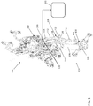
- the landing gear system 100 includes a landing gear collar 102 and a strut assembly 104.
- the strut assembly 104 includes a piston 106 moveably coupled to a strut linkage 108.
- the piston 106 slides vertically within a strut cylinder 110 included with the landing gear collar 102, which allows the piston 106 to be displaced between a fully extended position and a fully compressed position.
- the strut linkage 108 includes an upper torque link 112 and a lower torque link 114.
- the upper torque link 112 extends from a first upper link end 116 to a second upper link end 118.
- the first upper link end 116 is pivotably coupled to the landing gear collar 102 (e.g., the strut cylinder 110) via an upper link pin 120.
- the lower link end 118 is pivotably coupled to a torque link apex pin 122.
- the lower torque link 114 extends from a first lower link end 124 to a second lower link end 126.
- the first lower link end 124 is pivotably coupled to a piston bracket 128 attached to the piston 106 via a lower link pin 130.
- the second lower link end 126 is pivotably coupled in common with the second upper link end 118 via the torque link apex pin 122.
- the piston 106 and strut linkage 108 can further be coupled to a wheel positioning system (not shown), which adjusts a tilting position of the wheel assembly.
- the wheel positioning system includes several additional links that are adjusted in response to adjusting the piston 106 and the strut linkage 108. For example, sliding the piston 106 between the fully extended position and the fully compressed position causes adjustment of the strut linkage 108. The movement of the strut linkage 108 causes adjustment of the wheel position system, which in turn adjusts the tiling position of the wheel assembly.
- the landing gear system 100 further includes a rotary encoder 200 in signal communication with a controller 202.
- the rotary encoder 200 is rotatably coupled to the upper link pin 120. Accordingly, the rotary encoder 200 rotates in response to pivoting the first upper link end 116 with the upper link pin 120.
- the first upper link end 116 pivots with the torque link pin about a center of rotation in response to displacing the piston 106 either upwards or downwards. Accordingly, the angular displacement with respect to the axis of the piston 106 changes based on the geometry of the linkage 108.
- the rotary encoder 200 undergoes the same angular displacement as the upper torque link 112. This arrangement allows the rotary encoder 200 to operate as a sensor. In response to rotating the upper torque link 112, the rotary sensor 200 outputs a data signal that indicates the angular displacement of the upper torque link 112. The angular displacement of the upper torque link 112 is related to the stroke of the piston 106.
- the controller 202 determines the angular displacement based on the data signal output by the rotary encoder 200, and calculates the stroke of the piston 106. The calculation of the stroke based on the positions of the piston 106, strut linkage 108, and rotary encoder 200 are described in greater detail below.
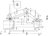
- FIG. 2A illustrates the strut system 102 with the piston 106 residing in the fully extended position.
- the piston 106 includes an upper end 132 that slides vertically within a strut cylinder 110 included with the landing gear collar (not shown in FIGS. 2A-2B ), thereby allowing the piston 106 to be displaced between the fully extended position to the fully compressed position.
- the upper link pin 120 is aligned with a first axis 134 that extends through the cylinder 110, which is fixed in place.
- the lower end 136 of the piston 106 is aligned with a second axis 138, which defines the lowest position of the piston 106 when displaced in the fully extended position.
- the lower link pin 130 is aligned with a third axis 140, which extends through the piston 106 and moves therewith. Accordingly, the second axis 136 moves upwards and downwards with respect to the first axis 134 and the second axis 138.
- the perpendicular distance between the upper and lower link pins 120 and 130 is the greatest, when the piston 106 resides in the fully extended position. As the piston 106 is compressed, the span decreases. The change in span can represent the stroke of the piston 106.
- the geometrical design of the linkage 108 defines a varying angle ( a ).
- the varying angle varying angle ( a ) defines a changing angle of the upper torque link 112 with respect to a fourth axis 142 that extends through the torque link pin 120 and maintains alignment therewith as the linkage 112 is adjusted.
- the varying angle ( a ) can be used to determine stroke of the piston 106 as described in greater detail below.
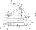
- the piston 106 is shown residing in the fully compressed position.
- the piston head 132 is shown being moved upward such that the lower piston end 136 is displaced from the second axis 138.
- the third axis 140 is also shown as being moved upward. Accordingly, the stroke of the piston 106 can be defined as the distance between the second axis 138 and the adjusted position of the third axis 140.
- the varying angle ( a ) of the linkage is also changed (e.g., increased).
- the upper torque link 112 is adjusted and the varying angle ( a ) changes.
- the rotary encoder 200 coupled to the upper torque link 112 also realizes the same angular displacement as the upper torque link 112. In this manner, the output of the rotary encoder 200 can indicate the angular displacement of the upper torque link 112.
- a relationship between the angular displacement of the upper torque link 112 and the stroke of the piston 106 can then be defined. Accordingly, the angular displacement of the upper torque link 112 is can be utilized to determine the stroke of the piston 106.
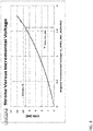
- FIG. 3 illustrates a relationship between the output of the rotary encoder 200 and the stroke of the piston 106.
- the angular incremental voltage (V_ANG_INC) output from the rotary encoder 200 can be cross-referenced to corresponding value (Stroke) representing the distance at which the piston is displaced from the second axis 138. This distance is defined as the piston stroke.
- the relationship of the angular incremental voltage (V_ANG_INC) and the stroke can be tabulated in a look-up table (LUT) 204, which is stored in the processor 202.
- the processor 202 can then obtain the output of the rotary encoder 200 and match the angular incremental voltage (V_ANG_INC) to a matching voltage value, which in turn corresponds to the current stroke of the piston 106.
- the rotary encoder 200 can undergo a calibration process upon its initial installation. One or more steps of the calibration process can be performed while the aircraft is grounded and upon initial installation of the rotary encoder 200.
- the calibration then allows for dynamically correcting the angular incremental voltage (V_ANG_INC) during subsequent operation to provide a more accurate piston stroke measurement. For example, after installing the rotary encoder 200, stroke values (S_x) are manually measured over the span of the piston 106, and the corresponding voltage (V_ANG_Sx) output from the voltage encoder 200 for each manually adjusted position is recorded. Once a technician rules that the (Sx) and (V_ANG_Sx) measurements are accurate, the measured values can be stored in the processor 202 for future stroke determination.
- a sample set of voltage readings e.g., 10-20 voltage readings are obtained, and the average of the voltage readings is set as the rotary encoder output voltage (V_ANG_EXT) corresponding to the fully extended position of the piston 106.
- the controller 200 can apply a correction value (ERR_Sx) to the angular incremental voltage (V_ANG_INC) during subsequent operation to provide a more accurate piston stroke measurement.
- the calculated parameters Sx, V_ANG_Sx, V_ANG_INC_Sx, ERR_Sx, and V_ANG_EXT are stored in the memory of the controller 202.
- V_ANG_INC_Sx_N is obtained from the LUT 204 for a given manually measured stroke value.
- V_ANG_INC_ADJ V_ANG_INC + ERR_Sx / V_ANG_INC_Sx * V_ANG_INC .
- the controller 202 compares the corrected angular incremental voltage to the stored angular incremental voltages listed in the LUT 204 to determine the stroke of the piston 106.
- FIG. 4 a method of calibrating a rotary encoder installed in the landing gear system is illustrated according to a no-limiting embodiment.
- the method begins at operation 400, and at operation 402 the piston is set to the fully extended position.
- the output voltage (V_ANG_EXT) of the rotary encoder is measured while the piston resides in the fully extended position.
- the initial voltage measured when the piston resides in the fully extended position is utilized as a reference voltage to determine future stroke measurements.
- the piston is displaced from its current position, and at operation 408 the stroke (Sx) is measured based on the displacement of the piston.
- the stroke is measured as the distance between the current position of the piston and the position of the piston when residing in the fully extended position.
- the rotary encoder output () is measured for a given stroke (Sx), and V_ANG_INC_Sx is computed.
- V_ANG_INC_Sx_N is determined for the stroke (Sx) based on the LUT, and at operation 414 the error correction value (ERR_Sx) at the stroke Sx is determined.
- the incremental rotary encoder voltage (V_ANG_INC_Sx) for the measured stroke position (Sx), the rotary output voltage (V_ANG_EXT) corresponding to the fully extended position of the piston, and the error correction (ERR_Sx) at the stroke position (Sx) are stored in memory to be used to calculate a future stroke of the piston, and the method ends at operation 416.
- a method of determining a stroke of a piston included in the landing gear system 100 is illustrated according to a non-limiting embodiment.
- the method begins at operation 500, and at operation 502 the rotary encoder output (V_ANG) corresponding to the current position of the rotary encoder is obtained.
- the angular incremental voltage (V_ANG_INC) is determined.
- the angular incremental voltage is adjusted to generate a corrected angular incremental voltage (V_ANG_INC_ADJ).
- the corrected angular incremental voltage is using the calibration parameters generated according to the calibration procedure described herein and which are subsequently stored in the memory of the controller.
- the corrected angular incremental voltage (V_ANG_INC_ADJ) is utilized along with a LUT to determine the current stroke of the piston.
- the LUT tabulates several angular incremental voltage values that are cross-referenced to a corresponding stroke position value. Accordingly, the corrected angular incremental voltage can be compared to the listing of stored angular incremental voltage values.
- the current stroke position is determined based on a match between the corrected angular incremental voltage (V_ANG_INC_ADJ) and an angular incremental voltage value listed in the LUT.
- the current stroke position is provided as a feedback input to the controller. Accordingly, the feedback can be utilized as a feedback value to control the landing gear system (e.g., to move the piston and adjust the tilted position of the wheel assembly), and the method ends at operation 514.
Landscapes
- Engineering & Computer Science (AREA)
- Aviation & Aerospace Engineering (AREA)
- Mechanical Engineering (AREA)
- Physics & Mathematics (AREA)
- General Physics & Mathematics (AREA)
- Manufacturing & Machinery (AREA)
- Transportation (AREA)
- Measurement Of Length, Angles, Or The Like Using Electric Or Magnetic Means (AREA)
- Transmission And Conversion Of Sensor Element Output (AREA)
Abstract
Description
- This application claims the benefit of Indian Application No.
201811037756 filed October 5, 2018 - Exemplary embodiments pertain to the art of aircraft systems, and more particularly, to aircraft landing gear systems.
- Aircraft landing gear systems typically include a moveable strut assembly, which includes a piston that slides between a fully extended position and a fully compressed position. The distance from the fully extended position to one or more compressed positions is typically referred to as the "piston stroke". In some aircraft landing systems piston is pivotably coupled to a tilting wheel assembly. As the piston slides between the fully extended position and the fully compressed position, the wheel assembly is adjusted from a fully tilted position (e.g., angled with respect to the ground surface) used to stow the wheels in the wheel well, for example, to a less-tilted landing position (e.g. parallel with respect to the ground surface). Accordingly, the stroke of the piston can be used as feedback control information for adjusting the wheel assembly into the correct desired position.
- Conventional Aircraft landing gear systems employ a linear variable differential transformer (LVDT) to measure the stroke. The LVDT is an electromechanical device with one primary coil and two secondary coils. The primary winding is excited by AC signal and the secondary coil voltages are measured. The secondary coil voltages depend on the location of the LVDT armature with respect to its electrical null point. When the armature is located at the electrical null point, the secondary coil voltages are equal. As the LVDT armature moves towards say the first secondary coil, the voltage associated with the first secondary increases, while the voltage of the remaining secondary coil decreases. In this manner, the secondary coil voltages can be utilized to compute the stroke.
- Disclosed is a landing gear system that includes a landing gear collar and a strut assembly supported by the landing gear collar. The strut assembly includes a piston that is adjustable between a fully extended position and a fully compress position. The landing gear system further includes a rotary encoder and a controller. The rotary encoder rotates in response adjusting the piston and to outputs a data value in response to its rotation. The controller is in signal communication with the rotary encoder and determines a stroke of the piston based on the data value output from the rotary encoder.
- Also disclosed is a method of determining a stroke of a piston. The method comprises adjusting a piston included in a strut assembly between a fully extended position and a fully compress position, and rotating a rotary encoder in response adjusting the piston. The method further comprises outputting a data value from the rotating encoder in response to rotating the rotary encoder, and determining, via a controller, the stroke of the piston based on the data value output from the rotary encoder.
- The following descriptions should not be considered limiting in any way. With reference to the accompanying drawings, like elements are numbered alike:
-
FIG. 1 is a perspective view of a landing gear system according to a non-limiting embodiment; -
FIG. 2A is a side-view of the landing gear system ofFIG. 1 operating in a fully extended position according to a non-limiting embodiment; -
FIG. 2B is a side-view of the landing gear system ofFIG. 1 operating in a fully compressed position according to a non-limiting embodiment; -
FIG. 3 is a chart illustrating a relationship between the output rotary encoder voltage and a stroke of a piston included in the landing gear system according to a non-limiting embodiment; -
FIG. 4 illustrates a flow diagram depicting a method of calibrating a rotary encoder installed in a landing gear system according to a non-limiting embodiment; and -
FIG. 5 is a flow diagram illustrating a method of determining a stroke of a piston included in the landing gear system according to a non-limiting embodiment. - A detailed description of one or more embodiments of the disclosed apparatus and method are presented herein by way of exemplification and not limitation with reference to the Figures.
- The term "about" is intended to include the degree of error associated with measurement of the particular quantity based upon the equipment available at the time of filing the application.
- Although the LVDT currently implemented in landing gear systems can determine the stroke associated with the strut assembly, the computed stroke measurement can suffer from inaccuracies. Electromagnetic fields, for example, can manipulate the voltages across the primary and/or secondary coils causing erroneous voltage measurements. The LVDT requires excessive mechanical components to facilitate connection of the LVDT to the sliding piston. For example, the LVDT requires mechanical rigging to precisely locate the LVDT null point with reference to the fully extended portion of the piston. These additional mechanical components can wear over time, thereby introducing further errors into the measured stroke.
- Various non-limiting embodiments described herein replaces the LVDT with a configurable rotary encoder capable of improving the accuracy of the measured stroke. The rotary encoder also omits the excessive mechanical components utilized by the LDVT, thereby improving long-term durability. Instead of utilizing a LDVT, which requires attaching a separate armature to the sliding piston, the rotary encoder is rotatably coupled to an upper torque link pin of the strut assembly and rotates in response to the sliding motion of the piston. As the piston is displaced, the torque link pin rotates thereby realizing a rotational angular displacement. A relationship between the rotational angular displacement and the displacement of the piston can be determined, which in turn can be used to determine the stroke of the piston without being susceptible to electromagnetic field interruptions.
- In addition, the output of the rotary encoder can be calibrated following its initial installation. Once calibrated, subsequent errors in the output measurements can be dynamically corrected to provide improved stroke measurements that take into consideration errors introduced by mechanical tolerances and variations in component designs. In at least one embodiment, the calibration is preformed according to a two-stage process. For example, a first stage of the calibration process includes manual measurements performed while the aircraft is grounded following the initial installation of the rotary encoder. A second stage of the calibration process occurs while the aircraft realizes pressure changes during its first flight following installation of the rotary encoder.
- With reference now to
FIG. 1 , alanding gear system 100 is illustrated according to a non-limiting embodiment. Thelanding gear system 100 includes alanding gear collar 102 and astrut assembly 104. Thestrut assembly 104 includes apiston 106 moveably coupled to astrut linkage 108. Thepiston 106 slides vertically within astrut cylinder 110 included with thelanding gear collar 102, which allows thepiston 106 to be displaced between a fully extended position and a fully compressed position. - The
strut linkage 108 includes anupper torque link 112 and alower torque link 114. Theupper torque link 112 extends from a firstupper link end 116 to a secondupper link end 118. The firstupper link end 116 is pivotably coupled to the landing gear collar 102 (e.g., the strut cylinder 110) via anupper link pin 120. Thelower link end 118 is pivotably coupled to a torquelink apex pin 122. - The
lower torque link 114 extends from a firstlower link end 124 to a secondlower link end 126. The firstlower link end 124 is pivotably coupled to apiston bracket 128 attached to thepiston 106 via alower link pin 130. The secondlower link end 126 is pivotably coupled in common with the secondupper link end 118 via the torquelink apex pin 122. - The
piston 106 and strutlinkage 108 can further be coupled to a wheel positioning system (not shown), which adjusts a tilting position of the wheel assembly. The wheel positioning system includes several additional links that are adjusted in response to adjusting thepiston 106 and thestrut linkage 108. For example, sliding thepiston 106 between the fully extended position and the fully compressed position causes adjustment of thestrut linkage 108. The movement of thestrut linkage 108 causes adjustment of the wheel position system, which in turn adjusts the tiling position of the wheel assembly. - Still referring to
FIG. 1 , thelanding gear system 100 further includes arotary encoder 200 in signal communication with acontroller 202. Therotary encoder 200 is rotatably coupled to theupper link pin 120. Accordingly, therotary encoder 200 rotates in response to pivoting the firstupper link end 116 with theupper link pin 120. For example, the firstupper link end 116 pivots with the torque link pin about a center of rotation in response to displacing thepiston 106 either upwards or downwards. Accordingly, the angular displacement with respect to the axis of thepiston 106 changes based on the geometry of thelinkage 108. - The
rotary encoder 200 undergoes the same angular displacement as theupper torque link 112. This arrangement allows therotary encoder 200 to operate as a sensor. In response to rotating theupper torque link 112, therotary sensor 200 outputs a data signal that indicates the angular displacement of theupper torque link 112. The angular displacement of theupper torque link 112 is related to the stroke of thepiston 106. Thecontroller 202 determines the angular displacement based on the data signal output by therotary encoder 200, and calculates the stroke of thepiston 106. The calculation of the stroke based on the positions of thepiston 106,strut linkage 108, androtary encoder 200 are described in greater detail below. - Turning now to
FIGS. 2A and2B , operation of thestrut system 102 is illustrated in greater detail.FIG. 2A illustrates thestrut system 102 with thepiston 106 residing in the fully extended position. Thepiston 106 includes anupper end 132 that slides vertically within astrut cylinder 110 included with the landing gear collar (not shown inFIGS. 2A-2B ), thereby allowing thepiston 106 to be displaced between the fully extended position to the fully compressed position. Theupper link pin 120 is aligned with afirst axis 134 that extends through thecylinder 110, which is fixed in place. Thelower end 136 of thepiston 106 is aligned with asecond axis 138, which defines the lowest position of thepiston 106 when displaced in the fully extended position. Thelower link pin 130 is aligned with athird axis 140, which extends through thepiston 106 and moves therewith. Accordingly, thesecond axis 136 moves upwards and downwards with respect to thefirst axis 134 and thesecond axis 138. In addition, the perpendicular distance between the upper and lower link pins 120 and 130 is the greatest, when thepiston 106 resides in the fully extended position. As thepiston 106 is compressed, the span decreases. The change in span can represent the stroke of thepiston 106. - The geometrical design of the
linkage 108 defines a varying angle (a). The varying angle varying angle (a) defines a changing angle of theupper torque link 112 with respect to afourth axis 142 that extends through thetorque link pin 120 and maintains alignment therewith as thelinkage 112 is adjusted. The varying angle (a) can be used to determine stroke of thepiston 106 as described in greater detail below. - Turning to
FIG. 2B , thepiston 106 is shown residing in the fully compressed position. For instance, thepiston head 132 is shown being moved upward such that thelower piston end 136 is displaced from thesecond axis 138. Thethird axis 140 is also shown as being moved upward. Accordingly, the stroke of thepiston 106 can be defined as the distance between thesecond axis 138 and the adjusted position of thethird axis 140. - The varying angle (a) of the linkage is also changed (e.g., increased). For example, as the
piston 106 is displaced, theupper torque link 112 is adjusted and the varying angle (a) changes. Therotary encoder 200 coupled to theupper torque link 112 also realizes the same angular displacement as theupper torque link 112. In this manner, the output of therotary encoder 200 can indicate the angular displacement of theupper torque link 112. A relationship between the angular displacement of theupper torque link 112 and the stroke of thepiston 106 can then be defined. Accordingly, the angular displacement of theupper torque link 112 is can be utilized to determine the stroke of thepiston 106. -
FIG. 3 , for example, illustrates a relationship between the output of therotary encoder 200 and the stroke of thepiston 106. In at least one embodiment, the angular incremental voltage (V_ANG_INC) output from therotary encoder 200 can be cross-referenced to corresponding value (Stroke) representing the distance at which the piston is displaced from thesecond axis 138. This distance is defined as the piston stroke. - In at least one embodiment, the relationship of the angular incremental voltage (V_ANG_INC) and the stroke can be tabulated in a look-up table (LUT) 204, which is stored in the
processor 202. Theprocessor 202 can then obtain the output of therotary encoder 200 and match the angular incremental voltage (V_ANG_INC) to a matching voltage value, which in turn corresponds to the current stroke of thepiston 106. - In at least one embodiment, the
rotary encoder 200 can undergo a calibration process upon its initial installation. One or more steps of the calibration process can be performed while the aircraft is grounded and upon initial installation of therotary encoder 200. The calibration then allows for dynamically correcting the angular incremental voltage (V_ANG_INC) during subsequent operation to provide a more accurate piston stroke measurement. For example, after installing therotary encoder 200, stroke values (S_x) are manually measured over the span of thepiston 106, and the corresponding voltage (V_ANG_Sx) output from thevoltage encoder 200 for each manually adjusted position is recorded. Once a technician rules that the (Sx) and (V_ANG_Sx) measurements are accurate, the measured values can be stored in theprocessor 202 for future stroke determination. - In one or more embodiments, a sample set of voltage readings (e.g., 10-20 voltage readings are obtained, and the average of the voltage readings is set as the rotary encoder output voltage (V_ANG_EXT) corresponding to the fully extended position of the
piston 106. The rotary encoder voltages (V_ANG_INC_Sx) for each stroke position can then be calculated as:
- When the aircraft performs the next flight following installation of the
rotary encoder 202, pressure readings can be performed while the aircraft is in flight. The recorded parameters are then be stored in non-volatile memory of thecontroller 202. - As described herein, the
controller 200 can apply a correction value (ERR_Sx) to the angular incremental voltage (V_ANG_INC) during subsequent operation to provide a more accurate piston stroke measurement. In at least one embodiment, the controller calculates the correction value (ERR_Sx) based on the following equation:
- In at least one embodiment, the calculated parameters Sx, V_ANG_Sx, V_ANG_INC_Sx, ERR_Sx, and V_ANG_EXT are stored in the memory of the
controller 202. In at least one embodiment, V_ANG_INC_Sx_N is obtained from theLUT 204 for a given manually measured stroke value. - Following calibration of the
rotary encoder 200, thecontroller 202 can determine the piston stroke during operation of thelanding gear system 100. For example, thecontroller 202 determines the output rotary encoder voltage (V_ANG) and computes the incremental rotary encoder voltage as:
- Once the incremental rotary encoder voltage is computed, the
controller 202 computes the corrected angular incremental voltage as:
- The
controller 202 then compares the corrected angular incremental voltage to the stored angular incremental voltages listed in theLUT 204 to determine the stroke of thepiston 106. - Turning to
FIG. 4 , for example, a method of calibrating a rotary encoder installed in the landing gear system is illustrated according to a no-limiting embodiment. The method begins atoperation 400, and atoperation 402 the piston is set to the fully extended position. Atoperation 404, the output voltage (V_ANG_EXT) of the rotary encoder is measured while the piston resides in the fully extended position. The initial voltage measured when the piston resides in the fully extended position is utilized as a reference voltage to determine future stroke measurements. Atoperation 406, the piston is displaced from its current position, and atoperation 408 the stroke (Sx) is measured based on the displacement of the piston. In at least one embodiment, the stroke is measured as the distance between the current position of the piston and the position of the piston when residing in the fully extended position. Atoperation 410, the rotary encoder output () is measured for a given stroke (Sx), and V_ANG_INC_Sx is computed. Atoperation 412, V_ANG_INC_Sx_N is determined for the stroke (Sx) based on the LUT, and atoperation 414 the error correction value (ERR_Sx) at the stroke Sx is determined. Atoperation 416, the incremental rotary encoder voltage (V_ANG_INC_Sx) for the measured stroke position (Sx), the rotary output voltage (V_ANG_EXT) corresponding to the fully extended position of the piston, and the error correction (ERR_Sx) at the stroke position (Sx) are stored in memory to be used to calculate a future stroke of the piston, and the method ends atoperation 416. - Referring to
FIG. 5 , a method of determining a stroke of a piston included in thelanding gear system 100 is illustrated according to a non-limiting embodiment. The method begins atoperation 500, and atoperation 502 the rotary encoder output (V_ANG) corresponding to the current position of the rotary encoder is obtained. Atoperation 504, the angular incremental voltage (V_ANG_INC) is determined. Atoperation 506, the angular incremental voltage is adjusted to generate a corrected angular incremental voltage (V_ANG_INC_ADJ). In at least one embodiment, the corrected angular incremental voltage is using the calibration parameters generated according to the calibration procedure described herein and which are subsequently stored in the memory of the controller. Atoperation 508, the corrected angular incremental voltage (V_ANG_INC_ADJ) is utilized along with a LUT to determine the current stroke of the piston. For example, the LUT tabulates several angular incremental voltage values that are cross-referenced to a corresponding stroke position value. Accordingly, the corrected angular incremental voltage can be compared to the listing of stored angular incremental voltage values. Atoperation 510, the current stroke position is determined based on a match between the corrected angular incremental voltage (V_ANG_INC_ADJ) and an angular incremental voltage value listed in the LUT. Atoperation 512, the current stroke position is provided as a feedback input to the controller. Accordingly, the feedback can be utilized as a feedback value to control the landing gear system (e.g., to move the piston and adjust the tilted position of the wheel assembly), and the method ends atoperation 514. - The terminology used herein is for the purpose of describing particular embodiments only and is not intended to be limiting of the present disclosure. As used herein, the singular forms "a", "an" and "the" are intended to include the plural forms as well, unless the context clearly indicates otherwise. It will be further understood that the terms "comprises" and/or "comprising," when used in this specification, specify the presence of stated features, integers, steps, operations, elements, and/or components, but do not preclude the presence or addition of one or more other features, integers, steps, operations, element components, and/or groups thereof.
- While the present disclosure has been described with reference to an exemplary embodiment or embodiments, it will be understood by those skilled in the art that various changes may be made and equivalents may be substituted for elements thereof without departing from the scope of the present disclosure. In addition, many modifications may be made to adapt a particular situation or material to the teachings of the present disclosure without departing from the essential scope thereof. Therefore, it is intended that the present disclosure not be limited to the particular embodiment disclosed as the best mode contemplated for carrying out this present disclosure, but that the present disclosure will include all embodiments falling within the scope of the claims.
Claims (15)
- A landing gear system comprising:a landing gear collar;a strut assembly supported by the landing gear collar, the strut assembly including a piston that is adjustable between a fully extended position and a fully compressed position;a rotary encoder rotatably coupled to the strut assembly, the rotary encoder configured to rotate in response to adjusting the piston and to output a data value in response to rotating the rotary encoder; anda controller in signal communication with the rotary encoder and configured to determine a stroke of the piston based on the data value output from the rotary encoder.
- The landing gear of claim 1, wherein the strut assembly further comprises a strut linkage configured to adjust in response to adjusting the piston.
- The landing gear of claim 2 wherein the rotary encoder is coupled to the strut linkage and rotates in response to adjusting the strut linkage.
- The landing gear of any preceding claim, wherein the piston is configured to move between a fully extended position and a fully compressed position.
- The landing gear of any preceding claim, wherein the data value output from the rotary encoder is a voltage level.
- The landing gear of claim 5, wherein the controller stores a plurality of pre-determined voltages that are cross-referenced to a respective stroke position of the piston, and determines the stroke based on a comparison between the voltage level and the plurality of pre-determined voltages.
- The landing gear of claim 5 or 6, wherein the controller dynamically adjusts the voltage level based on a correction value, and determines the stroke based on the adjusted voltage level.
- A method of determining a stroke of a piston, the method comprising:adjusting a piston included in a strut assembly between a fully extended position and a fully compressed position;rotating a rotary encoder in response to adjusting the piston; andoutputting a data value from the rotating encoder in response to rotating the rotary encoder; anddetermining, via a controller, the stroke of the piston based on the data value output from the rotary encoder.
- The method of claim 8, wherein the strut assembly comprises a strut linkage that adjusts in response to adjusting the piston, and the method comprises rotatably coupling the rotary encoder to the strut linkage.
- The method of claim 9, further comprising outputting the data value in response to adjusting the strut linkage.
- The method of any one of claims 8-10, further comprising moving the piston between a fully extended position and a fully compressed position, and determining the data value based on a difference between an adjusted position of the piston and the fully compressed position.
- The method of any one of claims 8-11, wherein the data value output from the rotary encoder is a voltage level.
- The method of claim 12, further comprising:storing, in a look-up table of the controller, a plurality of pre-determined voltages that are cross-referenced to a respective stroke position of the piston; anddetermining, via the controller, the stroke based on a comparison between the voltage level and the plurality of pre-determined voltages.
- The method of claim 12 or 13, further comprising:determining a correction value;storing the correction value in a memory unit; anddynamically adjusting, via the controller, the voltage level based on the correction value.
- The method of claim 14, further comprising determining, via the controller, the stroke based on the adjusted voltage level.
Applications Claiming Priority (1)
| Application Number | Priority Date | Filing Date | Title |
|---|---|---|---|
| IN201811037756 | 2018-10-05 |
Publications (2)
| Publication Number | Publication Date |
|---|---|
| EP3633322A1 true EP3633322A1 (en) | 2020-04-08 |
| EP3633322B1 EP3633322B1 (en) | 2024-08-07 |
Family
ID=68172127
Family Applications (1)
| Application Number | Title | Priority Date | Filing Date |
|---|---|---|---|
| EP19201748.1A Active EP3633322B1 (en) | 2018-10-05 | 2019-10-07 | Configurable rotary encoder including two point inflight auto calibration and error adjustment |
Country Status (3)
| Country | Link |
|---|---|
| US (1) | US11440647B2 (en) |
| EP (1) | EP3633322B1 (en) |
| CA (1) | CA3056104A1 (en) |
Cited By (2)
| Publication number | Priority date | Publication date | Assignee | Title |
|---|---|---|---|---|
| CN112556739A (en) * | 2020-11-11 | 2021-03-26 | 深圳市海浦蒙特科技有限公司 | Absolute position reference point calibration method and device of rotary encoder |
| DE102022109015A1 (en) | 2022-04-13 | 2023-10-19 | Liebherr-Aerospace Lindenberg Gmbh | Measuring system, linear motion element and aircraft |
Families Citing this family (5)
| Publication number | Priority date | Publication date | Assignee | Title |
|---|---|---|---|---|
| CN112249362B (en) * | 2020-10-13 | 2024-03-08 | 合肥市闪感智能科技有限公司 | A accurate measurement and control device of pillar corner for diamond unmanned aerial vehicle when descending |
| CN112918699B (en) * | 2021-01-20 | 2024-02-09 | 上海海鹰机械厂 | Trouble shooting method for raising pre-ignition and brightening of certain machine consumption group signal lamp |
| US12054282B2 (en) * | 2022-05-23 | 2024-08-06 | Safran Landing Systems Canada Inc. | Landing gear load detection system |
| CN117782187B (en) * | 2024-02-23 | 2024-05-07 | 泉州昆泰芯微电子科技有限公司 | Nonlinear error correction method of encoder and encoder |
| CN120039419B (en) * | 2025-03-31 | 2025-09-26 | 深标智能检测与评定技术服务(深圳)有限公司 | Unmanned aerial vehicle testing method, device and equipment |
Citations (4)
| Publication number | Priority date | Publication date | Assignee | Title |
|---|---|---|---|---|
| US20060284008A1 (en) * | 2005-03-29 | 2006-12-21 | Nance C K | Aircraft landing gear initial touch-down velocity monitor |
| US20120132742A1 (en) * | 2010-10-18 | 2012-05-31 | Honda Patents & Technologies North America, Llc | Quick release assembly for aircraft landing gear |
| US20140176037A1 (en) * | 2012-12-20 | 2014-06-26 | Canon Kabushiki Kaisha | Control unit of actuator |
| US20160298316A1 (en) * | 2015-03-27 | 2016-10-13 | Komatsu Ltd. | Calibration Device for Work Machine and Calibration Method of Working Equipment Parameter for Work Machine |
Family Cites Families (4)
| Publication number | Priority date | Publication date | Assignee | Title |
|---|---|---|---|---|
| US2921759A (en) * | 1955-12-09 | 1960-01-19 | North American Aviation Inc | Retractable landing gear |
| GB0714364D0 (en) | 2007-07-24 | 2007-09-05 | Goodrich Actuation Systems Ltd | Landing gear assembley |
| US8939400B2 (en) * | 2011-02-21 | 2015-01-27 | The Boeing Company | Air-ground detection system for semi-levered landing gear |
| US11104450B2 (en) * | 2018-05-14 | 2021-08-31 | Goodrich Corporation | Assemblies and methods for landing gear rotational position sensor installation |
-
2019
- 2019-04-24 US US16/393,019 patent/US11440647B2/en active Active
- 2019-09-19 CA CA3056104A patent/CA3056104A1/en active Pending
- 2019-10-07 EP EP19201748.1A patent/EP3633322B1/en active Active
Patent Citations (4)
| Publication number | Priority date | Publication date | Assignee | Title |
|---|---|---|---|---|
| US20060284008A1 (en) * | 2005-03-29 | 2006-12-21 | Nance C K | Aircraft landing gear initial touch-down velocity monitor |
| US20120132742A1 (en) * | 2010-10-18 | 2012-05-31 | Honda Patents & Technologies North America, Llc | Quick release assembly for aircraft landing gear |
| US20140176037A1 (en) * | 2012-12-20 | 2014-06-26 | Canon Kabushiki Kaisha | Control unit of actuator |
| US20160298316A1 (en) * | 2015-03-27 | 2016-10-13 | Komatsu Ltd. | Calibration Device for Work Machine and Calibration Method of Working Equipment Parameter for Work Machine |
Cited By (2)
| Publication number | Priority date | Publication date | Assignee | Title |
|---|---|---|---|---|
| CN112556739A (en) * | 2020-11-11 | 2021-03-26 | 深圳市海浦蒙特科技有限公司 | Absolute position reference point calibration method and device of rotary encoder |
| DE102022109015A1 (en) | 2022-04-13 | 2023-10-19 | Liebherr-Aerospace Lindenberg Gmbh | Measuring system, linear motion element and aircraft |
Also Published As
| Publication number | Publication date |
|---|---|
| US20200108917A1 (en) | 2020-04-09 |
| CA3056104A1 (en) | 2020-04-05 |
| BR102019020769A2 (en) | 2020-04-22 |
| US11440647B2 (en) | 2022-09-13 |
| EP3633322B1 (en) | 2024-08-07 |
Similar Documents
| Publication | Publication Date | Title |
|---|---|---|
| EP3633322B1 (en) | Configurable rotary encoder including two point inflight auto calibration and error adjustment | |
| RU2559611C2 (en) | Error correction device for cnc machines | |
| EP2037220B1 (en) | Displacement sensing method and motor control apparatus | |
| RU2717634C2 (en) | Method of positioner calibration, process control system and computer device for pressure control for calibration of process control devices | |
| US6967452B2 (en) | Operation apparatus with auto correction of position data of electric faders | |
| EP1209439A2 (en) | Position detection apparatus with correction for non-linear sensor regions | |
| EP1754962A2 (en) | Viscous material dispensing system and method with feedback control | |
| US20220363280A1 (en) | Calibration Adjustment For Automatic Steering Systems | |
| EP1065670A2 (en) | Apparatus and method for X-ray collimator sizing and alignment | |
| KR102338668B1 (en) | Sampling pipette having an improved device for adjusting and displaying a volume to be sampled | |
| EP3584541A1 (en) | Initialization method and initialization device | |
| CN110382873B (en) | Method for adjusting the rotational speed of a centrifugal pump | |
| EP3889516B1 (en) | Systems and methods for characterizing variable-air-volume (vav) valves for use in hvac systems | |
| CN110567349A (en) | stator blade rotation angle measuring structure and calibration method | |
| EP2669701B1 (en) | Calibration to improve weather radar positioning determination | |
| KR101604338B1 (en) | A load device using a leaf spring and an operation method thereof | |
| GB2054149A (en) | Rotameter-type flowmeter | |
| EP2799829A1 (en) | Method of and Calibration Device for Calibrating an Adjustable Mechanical Pointer Gauge | |
| BR102019020769B1 (en) | LANDING GEAR SYSTEM, AND METHOD FOR DETERMINING A PISTON MOVEMENT | |
| US7543595B2 (en) | Valve calibration method and apparatus | |
| WO2011081569A1 (en) | Method of adjusting position of riding cutoff valve | |
| US20210146527A1 (en) | Exoskeleton joint drive with non-linear transmission | |
| US5067100A (en) | Method of calibrating mechanical pressure gauges | |
| WO2005071816A9 (en) | Linear motor and transducer arrangement therefor | |
| CA1168466A (en) | Calibration adjustment for gauge instruments |
Legal Events
| Date | Code | Title | Description |
|---|---|---|---|
| PUAI | Public reference made under article 153(3) epc to a published international application that has entered the european phase |
Free format text: ORIGINAL CODE: 0009012 |
|
| STAA | Information on the status of an ep patent application or granted ep patent |
Free format text: STATUS: THE APPLICATION HAS BEEN PUBLISHED |
|
| AK | Designated contracting states |
Kind code of ref document: A1 Designated state(s): AL AT BE BG CH CY CZ DE DK EE ES FI FR GB GR HR HU IE IS IT LI LT LU LV MC MK MT NL NO PL PT RO RS SE SI SK SM TR |
|
| AX | Request for extension of the european patent |
Extension state: BA ME |
|
| STAA | Information on the status of an ep patent application or granted ep patent |
Free format text: STATUS: REQUEST FOR EXAMINATION WAS MADE |
|
| 17P | Request for examination filed |
Effective date: 20201007 |
|
| RBV | Designated contracting states (corrected) |
Designated state(s): AL AT BE BG CH CY CZ DE DK EE ES FI FR GB GR HR HU IE IS IT LI LT LU LV MC MK MT NL NO PL PT RO RS SE SI SK SM TR |
|
| STAA | Information on the status of an ep patent application or granted ep patent |
Free format text: STATUS: EXAMINATION IS IN PROGRESS |
|
| 17Q | First examination report despatched |
Effective date: 20220208 |
|
| RAP1 | Party data changed (applicant data changed or rights of an application transferred) |
Owner name: GOODRICH CORPORATION |
|
| REG | Reference to a national code |
Ref country code: DE Ref legal event code: R079 Free format text: PREVIOUS MAIN CLASS: G01D0005244000 Ref country code: DE Ref legal event code: R079 Ref document number: 602019056477 Country of ref document: DE Free format text: PREVIOUS MAIN CLASS: G01D0005244000 Ipc: B64C0025000000 |
|
| GRAP | Despatch of communication of intention to grant a patent |
Free format text: ORIGINAL CODE: EPIDOSNIGR1 |
|
| STAA | Information on the status of an ep patent application or granted ep patent |
Free format text: STATUS: GRANT OF PATENT IS INTENDED |
|
| RIC1 | Information provided on ipc code assigned before grant |
Ipc: G01D 18/00 20060101ALI20240221BHEP Ipc: G01D 5/244 20060101ALI20240221BHEP Ipc: B64C 25/00 20060101AFI20240221BHEP |
|
| INTG | Intention to grant announced |
Effective date: 20240307 |
|
| GRAS | Grant fee paid |
Free format text: ORIGINAL CODE: EPIDOSNIGR3 |
|
| GRAA | (expected) grant |
Free format text: ORIGINAL CODE: 0009210 |
|
| STAA | Information on the status of an ep patent application or granted ep patent |
Free format text: STATUS: THE PATENT HAS BEEN GRANTED |
|
| AK | Designated contracting states |
Kind code of ref document: B1 Designated state(s): AL AT BE BG CH CY CZ DE DK EE ES FI FR GB GR HR HU IE IS IT LI LT LU LV MC MK MT NL NO PL PT RO RS SE SI SK SM TR |
|
| REG | Reference to a national code |
Ref country code: GB Ref legal event code: FG4D |
|
| REG | Reference to a national code |
Ref country code: CH Ref legal event code: EP |
|
| REG | Reference to a national code |
Ref country code: DE Ref legal event code: R096 Ref document number: 602019056477 Country of ref document: DE |
|
| REG | Reference to a national code |
Ref country code: IE Ref legal event code: FG4D |
|
| REG | Reference to a national code |
Ref country code: LT Ref legal event code: MG9D |
|
| REG | Reference to a national code |
Ref country code: NL Ref legal event code: MP Effective date: 20240807 |
|
| PG25 | Lapsed in a contracting state [announced via postgrant information from national office to epo] |
Ref country code: NO Free format text: LAPSE BECAUSE OF FAILURE TO SUBMIT A TRANSLATION OF THE DESCRIPTION OR TO PAY THE FEE WITHIN THE PRESCRIBED TIME-LIMIT Effective date: 20241107 |
|
| REG | Reference to a national code |
Ref country code: AT Ref legal event code: MK05 Ref document number: 1710648 Country of ref document: AT Kind code of ref document: T Effective date: 20240807 |
|
| PG25 | Lapsed in a contracting state [announced via postgrant information from national office to epo] |
Ref country code: NL Free format text: LAPSE BECAUSE OF FAILURE TO SUBMIT A TRANSLATION OF THE DESCRIPTION OR TO PAY THE FEE WITHIN THE PRESCRIBED TIME-LIMIT Effective date: 20240807 Ref country code: PL Free format text: LAPSE BECAUSE OF FAILURE TO SUBMIT A TRANSLATION OF THE DESCRIPTION OR TO PAY THE FEE WITHIN THE PRESCRIBED TIME-LIMIT Effective date: 20240807 Ref country code: PT Free format text: LAPSE BECAUSE OF FAILURE TO SUBMIT A TRANSLATION OF THE DESCRIPTION OR TO PAY THE FEE WITHIN THE PRESCRIBED TIME-LIMIT Effective date: 20241209 Ref country code: FI Free format text: LAPSE BECAUSE OF FAILURE TO SUBMIT A TRANSLATION OF THE DESCRIPTION OR TO PAY THE FEE WITHIN THE PRESCRIBED TIME-LIMIT Effective date: 20240807 Ref country code: GR Free format text: LAPSE BECAUSE OF FAILURE TO SUBMIT A TRANSLATION OF THE DESCRIPTION OR TO PAY THE FEE WITHIN THE PRESCRIBED TIME-LIMIT Effective date: 20241108 |
|
| PG25 | Lapsed in a contracting state [announced via postgrant information from national office to epo] |
Ref country code: BG Free format text: LAPSE BECAUSE OF FAILURE TO SUBMIT A TRANSLATION OF THE DESCRIPTION OR TO PAY THE FEE WITHIN THE PRESCRIBED TIME-LIMIT Effective date: 20240807 |
|
| PG25 | Lapsed in a contracting state [announced via postgrant information from national office to epo] |
Ref country code: LV Free format text: LAPSE BECAUSE OF FAILURE TO SUBMIT A TRANSLATION OF THE DESCRIPTION OR TO PAY THE FEE WITHIN THE PRESCRIBED TIME-LIMIT Effective date: 20240807 |
|
| PG25 | Lapsed in a contracting state [announced via postgrant information from national office to epo] |
Ref country code: AT Free format text: LAPSE BECAUSE OF FAILURE TO SUBMIT A TRANSLATION OF THE DESCRIPTION OR TO PAY THE FEE WITHIN THE PRESCRIBED TIME-LIMIT Effective date: 20240807 Ref country code: IS Free format text: LAPSE BECAUSE OF FAILURE TO SUBMIT A TRANSLATION OF THE DESCRIPTION OR TO PAY THE FEE WITHIN THE PRESCRIBED TIME-LIMIT Effective date: 20241207 |
|
| PG25 | Lapsed in a contracting state [announced via postgrant information from national office to epo] |
Ref country code: HR Free format text: LAPSE BECAUSE OF FAILURE TO SUBMIT A TRANSLATION OF THE DESCRIPTION OR TO PAY THE FEE WITHIN THE PRESCRIBED TIME-LIMIT Effective date: 20240807 |
|
| PG25 | Lapsed in a contracting state [announced via postgrant information from national office to epo] |
Ref country code: RS Free format text: LAPSE BECAUSE OF FAILURE TO SUBMIT A TRANSLATION OF THE DESCRIPTION OR TO PAY THE FEE WITHIN THE PRESCRIBED TIME-LIMIT Effective date: 20241107 Ref country code: ES Free format text: LAPSE BECAUSE OF FAILURE TO SUBMIT A TRANSLATION OF THE DESCRIPTION OR TO PAY THE FEE WITHIN THE PRESCRIBED TIME-LIMIT Effective date: 20240807 |
|
| PG25 | Lapsed in a contracting state [announced via postgrant information from national office to epo] |
Ref country code: RS Free format text: LAPSE BECAUSE OF FAILURE TO SUBMIT A TRANSLATION OF THE DESCRIPTION OR TO PAY THE FEE WITHIN THE PRESCRIBED TIME-LIMIT Effective date: 20241107 Ref country code: PT Free format text: LAPSE BECAUSE OF FAILURE TO SUBMIT A TRANSLATION OF THE DESCRIPTION OR TO PAY THE FEE WITHIN THE PRESCRIBED TIME-LIMIT Effective date: 20241209 Ref country code: PL Free format text: LAPSE BECAUSE OF FAILURE TO SUBMIT A TRANSLATION OF THE DESCRIPTION OR TO PAY THE FEE WITHIN THE PRESCRIBED TIME-LIMIT Effective date: 20240807 Ref country code: NO Free format text: LAPSE BECAUSE OF FAILURE TO SUBMIT A TRANSLATION OF THE DESCRIPTION OR TO PAY THE FEE WITHIN THE PRESCRIBED TIME-LIMIT Effective date: 20241107 Ref country code: NL Free format text: LAPSE BECAUSE OF FAILURE TO SUBMIT A TRANSLATION OF THE DESCRIPTION OR TO PAY THE FEE WITHIN THE PRESCRIBED TIME-LIMIT Effective date: 20240807 Ref country code: LV Free format text: LAPSE BECAUSE OF FAILURE TO SUBMIT A TRANSLATION OF THE DESCRIPTION OR TO PAY THE FEE WITHIN THE PRESCRIBED TIME-LIMIT Effective date: 20240807 Ref country code: IS Free format text: LAPSE BECAUSE OF FAILURE TO SUBMIT A TRANSLATION OF THE DESCRIPTION OR TO PAY THE FEE WITHIN THE PRESCRIBED TIME-LIMIT Effective date: 20241207 Ref country code: HR Free format text: LAPSE BECAUSE OF FAILURE TO SUBMIT A TRANSLATION OF THE DESCRIPTION OR TO PAY THE FEE WITHIN THE PRESCRIBED TIME-LIMIT Effective date: 20240807 Ref country code: GR Free format text: LAPSE BECAUSE OF FAILURE TO SUBMIT A TRANSLATION OF THE DESCRIPTION OR TO PAY THE FEE WITHIN THE PRESCRIBED TIME-LIMIT Effective date: 20241108 Ref country code: FI Free format text: LAPSE BECAUSE OF FAILURE TO SUBMIT A TRANSLATION OF THE DESCRIPTION OR TO PAY THE FEE WITHIN THE PRESCRIBED TIME-LIMIT Effective date: 20240807 Ref country code: ES Free format text: LAPSE BECAUSE OF FAILURE TO SUBMIT A TRANSLATION OF THE DESCRIPTION OR TO PAY THE FEE WITHIN THE PRESCRIBED TIME-LIMIT Effective date: 20240807 Ref country code: BG Free format text: LAPSE BECAUSE OF FAILURE TO SUBMIT A TRANSLATION OF THE DESCRIPTION OR TO PAY THE FEE WITHIN THE PRESCRIBED TIME-LIMIT Effective date: 20240807 Ref country code: AT Free format text: LAPSE BECAUSE OF FAILURE TO SUBMIT A TRANSLATION OF THE DESCRIPTION OR TO PAY THE FEE WITHIN THE PRESCRIBED TIME-LIMIT Effective date: 20240807 |
|
| PG25 | Lapsed in a contracting state [announced via postgrant information from national office to epo] |
Ref country code: SM Free format text: LAPSE BECAUSE OF FAILURE TO SUBMIT A TRANSLATION OF THE DESCRIPTION OR TO PAY THE FEE WITHIN THE PRESCRIBED TIME-LIMIT Effective date: 20240807 Ref country code: RO Free format text: LAPSE BECAUSE OF FAILURE TO SUBMIT A TRANSLATION OF THE DESCRIPTION OR TO PAY THE FEE WITHIN THE PRESCRIBED TIME-LIMIT Effective date: 20240807 Ref country code: DK Free format text: LAPSE BECAUSE OF FAILURE TO SUBMIT A TRANSLATION OF THE DESCRIPTION OR TO PAY THE FEE WITHIN THE PRESCRIBED TIME-LIMIT Effective date: 20240807 |
|
| PG25 | Lapsed in a contracting state [announced via postgrant information from national office to epo] |
Ref country code: EE Free format text: LAPSE BECAUSE OF FAILURE TO SUBMIT A TRANSLATION OF THE DESCRIPTION OR TO PAY THE FEE WITHIN THE PRESCRIBED TIME-LIMIT Effective date: 20240807 |
|
| PG25 | Lapsed in a contracting state [announced via postgrant information from national office to epo] |
Ref country code: CZ Free format text: LAPSE BECAUSE OF FAILURE TO SUBMIT A TRANSLATION OF THE DESCRIPTION OR TO PAY THE FEE WITHIN THE PRESCRIBED TIME-LIMIT Effective date: 20240807 |
|
| PG25 | Lapsed in a contracting state [announced via postgrant information from national office to epo] |
Ref country code: SK Free format text: LAPSE BECAUSE OF FAILURE TO SUBMIT A TRANSLATION OF THE DESCRIPTION OR TO PAY THE FEE WITHIN THE PRESCRIBED TIME-LIMIT Effective date: 20240807 |
|
| REG | Reference to a national code |
Ref country code: DE Ref legal event code: R097 Ref document number: 602019056477 Country of ref document: DE |
|
| REG | Reference to a national code |
Ref country code: CH Ref legal event code: PL |
|
| PLBE | No opposition filed within time limit |
Free format text: ORIGINAL CODE: 0009261 |
|
| STAA | Information on the status of an ep patent application or granted ep patent |
Free format text: STATUS: NO OPPOSITION FILED WITHIN TIME LIMIT |
|
| PG25 | Lapsed in a contracting state [announced via postgrant information from national office to epo] |
Ref country code: MC Free format text: LAPSE BECAUSE OF FAILURE TO SUBMIT A TRANSLATION OF THE DESCRIPTION OR TO PAY THE FEE WITHIN THE PRESCRIBED TIME-LIMIT Effective date: 20240807 |
|
| PG25 | Lapsed in a contracting state [announced via postgrant information from national office to epo] |
Ref country code: BE Free format text: LAPSE BECAUSE OF NON-PAYMENT OF DUE FEES Effective date: 20241031 Ref country code: LU Free format text: LAPSE BECAUSE OF NON-PAYMENT OF DUE FEES Effective date: 20241007 |
|
| 26N | No opposition filed |
Effective date: 20250508 |
|
| PG25 | Lapsed in a contracting state [announced via postgrant information from national office to epo] |
Ref country code: CH Free format text: LAPSE BECAUSE OF NON-PAYMENT OF DUE FEES Effective date: 20241031 |
|
| REG | Reference to a national code |
Ref country code: BE Ref legal event code: MM Effective date: 20241031 |
|
| PG25 | Lapsed in a contracting state [announced via postgrant information from national office to epo] |
Ref country code: SE Free format text: LAPSE BECAUSE OF FAILURE TO SUBMIT A TRANSLATION OF THE DESCRIPTION OR TO PAY THE FEE WITHIN THE PRESCRIBED TIME-LIMIT Effective date: 20240807 |
|
| PGFP | Annual fee paid to national office [announced via postgrant information from national office to epo] |
Ref country code: GB Payment date: 20250923 Year of fee payment: 7 |
|
| PGFP | Annual fee paid to national office [announced via postgrant information from national office to epo] |
Ref country code: FR Payment date: 20250924 Year of fee payment: 7 |
|
| PG25 | Lapsed in a contracting state [announced via postgrant information from national office to epo] |
Ref country code: IE Free format text: LAPSE BECAUSE OF NON-PAYMENT OF DUE FEES Effective date: 20241007 |
|
| PGFP | Annual fee paid to national office [announced via postgrant information from national office to epo] |
Ref country code: DE Payment date: 20250923 Year of fee payment: 7 |
|
| PG25 | Lapsed in a contracting state [announced via postgrant information from national office to epo] |
Ref country code: IT Free format text: LAPSE BECAUSE OF FAILURE TO SUBMIT A TRANSLATION OF THE DESCRIPTION OR TO PAY THE FEE WITHIN THE PRESCRIBED TIME-LIMIT Effective date: 20240807 Ref country code: CY Free format text: LAPSE BECAUSE OF FAILURE TO SUBMIT A TRANSLATION OF THE DESCRIPTION OR TO PAY THE FEE WITHIN THE PRESCRIBED TIME-LIMIT; INVALID AB INITIO Effective date: 20191007 |
|
| PG25 | Lapsed in a contracting state [announced via postgrant information from national office to epo] |
Ref country code: HU Free format text: LAPSE BECAUSE OF FAILURE TO SUBMIT A TRANSLATION OF THE DESCRIPTION OR TO PAY THE FEE WITHIN THE PRESCRIBED TIME-LIMIT; INVALID AB INITIO Effective date: 20191007 |