EP3633306A1 - Heat exchanger - Google Patents
Heat exchanger Download PDFInfo
- Publication number
- EP3633306A1 EP3633306A1 EP18829086.0A EP18829086A EP3633306A1 EP 3633306 A1 EP3633306 A1 EP 3633306A1 EP 18829086 A EP18829086 A EP 18829086A EP 3633306 A1 EP3633306 A1 EP 3633306A1
- Authority
- EP
- European Patent Office
- Prior art keywords
- heat exchange
- exchange section
- refrigerant
- flat pipes
- sub
- Prior art date
- Legal status (The legal status is an assumption and is not a legal conclusion. Google has not performed a legal analysis and makes no representation as to the accuracy of the status listed.)
- Withdrawn
Links
- 239000003507 refrigerant Substances 0.000 claims description 275
- 238000004891 communication Methods 0.000 claims description 204
- 238000005192 partition Methods 0.000 claims description 26
- 238000010257 thawing Methods 0.000 description 76
- 238000010438 heat treatment Methods 0.000 description 50
- 239000007788 liquid Substances 0.000 description 49
- 238000002844 melting Methods 0.000 description 29
- 230000008018 melting Effects 0.000 description 29
- 238000012986 modification Methods 0.000 description 19
- 230000004048 modification Effects 0.000 description 19
- 238000001816 cooling Methods 0.000 description 17
- 230000017525 heat dissipation Effects 0.000 description 10
- 238000005057 refrigeration Methods 0.000 description 7
- 239000000470 constituent Substances 0.000 description 6
- 239000012530 fluid Substances 0.000 description 6
- 238000010586 diagram Methods 0.000 description 5
- 229920006395 saturated elastomer Polymers 0.000 description 4
- 230000006835 compression Effects 0.000 description 2
- 238000007906 compression Methods 0.000 description 2
- 238000009434 installation Methods 0.000 description 2
- 238000011144 upstream manufacturing Methods 0.000 description 2
- 229910000838 Al alloy Inorganic materials 0.000 description 1
- XAGFODPZIPBFFR-UHFFFAOYSA-N aluminium Chemical compound [Al] XAGFODPZIPBFFR-UHFFFAOYSA-N 0.000 description 1
- 229910052782 aluminium Inorganic materials 0.000 description 1
- 230000015572 biosynthetic process Effects 0.000 description 1
- 238000005219 brazing Methods 0.000 description 1
- 238000007796 conventional method Methods 0.000 description 1
- 238000001704 evaporation Methods 0.000 description 1
- 230000008020 evaporation Effects 0.000 description 1
- 238000012546 transfer Methods 0.000 description 1
- XLYOFNOQVPJJNP-UHFFFAOYSA-N water Substances O XLYOFNOQVPJJNP-UHFFFAOYSA-N 0.000 description 1
Images








Classifications
-
- F—MECHANICAL ENGINEERING; LIGHTING; HEATING; WEAPONS; BLASTING
- F28—HEAT EXCHANGE IN GENERAL
- F28D—HEAT-EXCHANGE APPARATUS, NOT PROVIDED FOR IN ANOTHER SUBCLASS, IN WHICH THE HEAT-EXCHANGE MEDIA DO NOT COME INTO DIRECT CONTACT
- F28D1/00—Heat-exchange apparatus having stationary conduit assemblies for one heat-exchange medium only, the media being in contact with different sides of the conduit wall, in which the other heat-exchange medium is a large body of fluid, e.g. domestic or motor car radiators
- F28D1/02—Heat-exchange apparatus having stationary conduit assemblies for one heat-exchange medium only, the media being in contact with different sides of the conduit wall, in which the other heat-exchange medium is a large body of fluid, e.g. domestic or motor car radiators with heat-exchange conduits immersed in the body of fluid
- F28D1/04—Heat-exchange apparatus having stationary conduit assemblies for one heat-exchange medium only, the media being in contact with different sides of the conduit wall, in which the other heat-exchange medium is a large body of fluid, e.g. domestic or motor car radiators with heat-exchange conduits immersed in the body of fluid with tubular conduits
- F28D1/047—Heat-exchange apparatus having stationary conduit assemblies for one heat-exchange medium only, the media being in contact with different sides of the conduit wall, in which the other heat-exchange medium is a large body of fluid, e.g. domestic or motor car radiators with heat-exchange conduits immersed in the body of fluid with tubular conduits the conduits being bent, e.g. in a serpentine or zig-zag
- F28D1/0475—Heat-exchange apparatus having stationary conduit assemblies for one heat-exchange medium only, the media being in contact with different sides of the conduit wall, in which the other heat-exchange medium is a large body of fluid, e.g. domestic or motor car radiators with heat-exchange conduits immersed in the body of fluid with tubular conduits the conduits being bent, e.g. in a serpentine or zig-zag the conduits having a single U-bend
- F28D1/0476—Heat-exchange apparatus having stationary conduit assemblies for one heat-exchange medium only, the media being in contact with different sides of the conduit wall, in which the other heat-exchange medium is a large body of fluid, e.g. domestic or motor car radiators with heat-exchange conduits immersed in the body of fluid with tubular conduits the conduits being bent, e.g. in a serpentine or zig-zag the conduits having a single U-bend the conduits having a non-circular cross-section
-
- F—MECHANICAL ENGINEERING; LIGHTING; HEATING; WEAPONS; BLASTING
- F28—HEAT EXCHANGE IN GENERAL
- F28D—HEAT-EXCHANGE APPARATUS, NOT PROVIDED FOR IN ANOTHER SUBCLASS, IN WHICH THE HEAT-EXCHANGE MEDIA DO NOT COME INTO DIRECT CONTACT
- F28D1/00—Heat-exchange apparatus having stationary conduit assemblies for one heat-exchange medium only, the media being in contact with different sides of the conduit wall, in which the other heat-exchange medium is a large body of fluid, e.g. domestic or motor car radiators
- F28D1/02—Heat-exchange apparatus having stationary conduit assemblies for one heat-exchange medium only, the media being in contact with different sides of the conduit wall, in which the other heat-exchange medium is a large body of fluid, e.g. domestic or motor car radiators with heat-exchange conduits immersed in the body of fluid
- F28D1/0233—Heat-exchange apparatus having stationary conduit assemblies for one heat-exchange medium only, the media being in contact with different sides of the conduit wall, in which the other heat-exchange medium is a large body of fluid, e.g. domestic or motor car radiators with heat-exchange conduits immersed in the body of fluid with air flow channels
- F28D1/024—Heat-exchange apparatus having stationary conduit assemblies for one heat-exchange medium only, the media being in contact with different sides of the conduit wall, in which the other heat-exchange medium is a large body of fluid, e.g. domestic or motor car radiators with heat-exchange conduits immersed in the body of fluid with air flow channels with an air driving element
-
- F—MECHANICAL ENGINEERING; LIGHTING; HEATING; WEAPONS; BLASTING
- F28—HEAT EXCHANGE IN GENERAL
- F28D—HEAT-EXCHANGE APPARATUS, NOT PROVIDED FOR IN ANOTHER SUBCLASS, IN WHICH THE HEAT-EXCHANGE MEDIA DO NOT COME INTO DIRECT CONTACT
- F28D1/00—Heat-exchange apparatus having stationary conduit assemblies for one heat-exchange medium only, the media being in contact with different sides of the conduit wall, in which the other heat-exchange medium is a large body of fluid, e.g. domestic or motor car radiators
- F28D1/02—Heat-exchange apparatus having stationary conduit assemblies for one heat-exchange medium only, the media being in contact with different sides of the conduit wall, in which the other heat-exchange medium is a large body of fluid, e.g. domestic or motor car radiators with heat-exchange conduits immersed in the body of fluid
- F28D1/04—Heat-exchange apparatus having stationary conduit assemblies for one heat-exchange medium only, the media being in contact with different sides of the conduit wall, in which the other heat-exchange medium is a large body of fluid, e.g. domestic or motor car radiators with heat-exchange conduits immersed in the body of fluid with tubular conduits
- F28D1/053—Heat-exchange apparatus having stationary conduit assemblies for one heat-exchange medium only, the media being in contact with different sides of the conduit wall, in which the other heat-exchange medium is a large body of fluid, e.g. domestic or motor car radiators with heat-exchange conduits immersed in the body of fluid with tubular conduits the conduits being straight
- F28D1/0535—Heat-exchange apparatus having stationary conduit assemblies for one heat-exchange medium only, the media being in contact with different sides of the conduit wall, in which the other heat-exchange medium is a large body of fluid, e.g. domestic or motor car radiators with heat-exchange conduits immersed in the body of fluid with tubular conduits the conduits being straight the conduits having a non-circular cross-section
- F28D1/05366—Assemblies of conduits connected to common headers, e.g. core type radiators
- F28D1/05383—Assemblies of conduits connected to common headers, e.g. core type radiators with multiple rows of conduits or with multi-channel conduits
-
- F—MECHANICAL ENGINEERING; LIGHTING; HEATING; WEAPONS; BLASTING
- F28—HEAT EXCHANGE IN GENERAL
- F28F—DETAILS OF HEAT-EXCHANGE AND HEAT-TRANSFER APPARATUS, OF GENERAL APPLICATION
- F28F9/00—Casings; Header boxes; Auxiliary supports for elements; Auxiliary members within casings
- F28F9/02—Header boxes; End plates
-
- F—MECHANICAL ENGINEERING; LIGHTING; HEATING; WEAPONS; BLASTING
- F28—HEAT EXCHANGE IN GENERAL
- F28F—DETAILS OF HEAT-EXCHANGE AND HEAT-TRANSFER APPARATUS, OF GENERAL APPLICATION
- F28F9/00—Casings; Header boxes; Auxiliary supports for elements; Auxiliary members within casings
- F28F9/02—Header boxes; End plates
- F28F9/0202—Header boxes having their inner space divided by partitions
- F28F9/0204—Header boxes having their inner space divided by partitions for elongated header box, e.g. with transversal and longitudinal partitions
- F28F9/0209—Header boxes having their inner space divided by partitions for elongated header box, e.g. with transversal and longitudinal partitions having only transversal partitions
-
- F—MECHANICAL ENGINEERING; LIGHTING; HEATING; WEAPONS; BLASTING
- F28—HEAT EXCHANGE IN GENERAL
- F28F—DETAILS OF HEAT-EXCHANGE AND HEAT-TRANSFER APPARATUS, OF GENERAL APPLICATION
- F28F9/00—Casings; Header boxes; Auxiliary supports for elements; Auxiliary members within casings
- F28F9/02—Header boxes; End plates
- F28F9/026—Header boxes; End plates with static flow control means, e.g. with means for uniformly distributing heat exchange media into conduits
- F28F9/027—Header boxes; End plates with static flow control means, e.g. with means for uniformly distributing heat exchange media into conduits in the form of distribution pipes
- F28F9/0275—Header boxes; End plates with static flow control means, e.g. with means for uniformly distributing heat exchange media into conduits in the form of distribution pipes with multiple branch pipes
-
- F—MECHANICAL ENGINEERING; LIGHTING; HEATING; WEAPONS; BLASTING
- F25—REFRIGERATION OR COOLING; COMBINED HEATING AND REFRIGERATION SYSTEMS; HEAT PUMP SYSTEMS; MANUFACTURE OR STORAGE OF ICE; LIQUEFACTION SOLIDIFICATION OF GASES
- F25B—REFRIGERATION MACHINES, PLANTS OR SYSTEMS; COMBINED HEATING AND REFRIGERATION SYSTEMS; HEAT PUMP SYSTEMS
- F25B39/00—Evaporators; Condensers
-
- F—MECHANICAL ENGINEERING; LIGHTING; HEATING; WEAPONS; BLASTING
- F28—HEAT EXCHANGE IN GENERAL
- F28D—HEAT-EXCHANGE APPARATUS, NOT PROVIDED FOR IN ANOTHER SUBCLASS, IN WHICH THE HEAT-EXCHANGE MEDIA DO NOT COME INTO DIRECT CONTACT
- F28D21/00—Heat-exchange apparatus not covered by any of the groups F28D1/00 - F28D20/00
- F28D2021/0019—Other heat exchangers for particular applications; Heat exchange systems not otherwise provided for
- F28D2021/0068—Other heat exchangers for particular applications; Heat exchange systems not otherwise provided for for refrigerant cycles
- F28D2021/0071—Evaporators
-
- F—MECHANICAL ENGINEERING; LIGHTING; HEATING; WEAPONS; BLASTING
- F28—HEAT EXCHANGE IN GENERAL
- F28F—DETAILS OF HEAT-EXCHANGE AND HEAT-TRANSFER APPARATUS, OF GENERAL APPLICATION
- F28F1/00—Tubular elements; Assemblies of tubular elements
- F28F1/10—Tubular elements and assemblies thereof with means for increasing heat-transfer area, e.g. with fins, with projections, with recesses
- F28F1/12—Tubular elements and assemblies thereof with means for increasing heat-transfer area, e.g. with fins, with projections, with recesses the means being only outside the tubular element
- F28F1/24—Tubular elements and assemblies thereof with means for increasing heat-transfer area, e.g. with fins, with projections, with recesses the means being only outside the tubular element and extending transversely
- F28F1/32—Tubular elements and assemblies thereof with means for increasing heat-transfer area, e.g. with fins, with projections, with recesses the means being only outside the tubular element and extending transversely the means having portions engaging further tubular elements
Definitions
- the present invention relates to a heat exchanger.
- the present invention relates to a heat exchanger including a plurality of flat pipes vertically arrayed, each of the flat pipes including a passage for a refrigerant formed inside thereof, and a plurality of fins that partition a space between adjacent flat pipes into a plurality of air flow passages through which air flows.
- a heat exchanger including a plurality of flat pipes vertically arrayed and a plurality of fins that partition a space between adjacent flat pipes into a plurality of air flow passages through which air flows may be employed as a heat exchanger housed in an outdoor unit (heat exchange unit) of an air conditioner.
- a heat exchanger includes a heat exchanger as described in Patent Literature 1 ( JP 2012-163313 A ) in which a plurality of flat pipes are divided into a plurality of heat exchange sections which are vertically arranged side by side, and each of the heat exchange sections includes a main heat exchange section and a sub heat exchange section which is connected in series to the main heat exchange section below the main heat exchange section.
- the above conventional heat exchanger may be employed in an air conditioner that performs a heating operation and a defrosting operation in a switching manner.
- the above conventional heat exchanger is used as an evaporator for a refrigerant.
- the above conventional heat exchanger is used as a radiator for the refrigerant.
- the refrigerant in a gas-liquid two-phase state is divided and flows into the sub heat exchange section included in each heat exchange section, is heated while passing through the sub heat exchange section and the main heat exchange section in that order, and flows out of the heat exchange section.
- the refrigerant in a gas state is divided and flows into the main heat exchange section of each heat exchange section, is cooled while passing through the main heat exchange section and the sub heat exchange section in that order, and flows out of the heat exchange section. Then, flows of the refrigerant merge with each other.
- the time required for melting frost adhered to the lowermost heat exchange section tends to become longer than the time required for melting frost adhered to the heat exchange section located on the upper side relative to the lowermost heat exchange section in the defrosting operation.
- frost may remain unmelted in the lowermost heat exchange section even after the defrosting operation, which may result in insufficient defrosting.
- a heat exchanger includes a plurality of flat pipes vertically arrayed, each of the flat pipes including a passage for a refrigerant formed inside of the flat pipe; and a plurality of fins that partition a space between each adjacent two of the flat pipes into a plurality of air flow passages through which air flows.
- the flat pipes are divided into a plurality of heat exchange sections, and each of the heat exchange sections includes a main heat exchange section connected to a gas-side entrance communication space and a sub heat exchange section connected in series to the main heat exchange section at a vertical position different from the main heat exchange section and connected to a liquid-side entrance communication space.
- one of the heat exchange sections including a lowermost one of the flat pipes is defined as a first heat exchange section
- the main heat exchange section and the sub heat exchange section that constitute the first heat exchange section are defined as a first main heat exchange section and a first sub heat exchange section
- the first main heat exchange section is disposed so as to include the lowermost flat pipe.
- a plurality of flat pipes are divided into a plurality of heat exchange sections which are vertically arranged side by side, and each of the heat exchange sections includes a main heat exchange section and a sub heat exchange section which is connected in series to the main heat exchange section below the main heat exchange section.
- the sub heat exchange section of the lowermost one of the heat exchange sections is disposed so as to include the lowermost flat pipe.
- the heating operation used as the evaporator for the refrigerant
- the defrosting operation used as the radiator for the refrigerant
- the refrigerant in a liquid state tends to be accumulated in the lowermost sub heat exchange section including the lowermost flat pipe.
- the defrosting operation is performed in such a condition, the refrigerant in a gas state first flows into the lowermost main heat exchange section and then flows into the lowermost sub heat exchange section.
- the lowermost sub heat exchange section including the lowermost flat pipe located on the downstream side in the refrigerant flow in the defrosting operation is one of the reasons why the time required for melting frost adhered to the lowermost heat exchange section becomes long in the defrosting operation.
- a flow rate of the refrigerant in a gas state flowing into the lowermost heat exchange section becomes lower than that in the upper heat exchange section due to the influence of a liquid head of the refrigerant, which increases the time required for melting frost adhered to the lowermost heat exchange section.
- the degree of the liquid head is affected by the height position of the flat pipe included in the sub heat exchange section of the heat exchange section.
- the liquid head of the refrigerant is large, and the flow rate of the refrigerant in a gas state flowing into the lowermost heat exchange section in the defrosting operation is further reduced. That is, it is assumed that, in the configuration of the conventional heat exchanger, a reduction in the flow rate of the refrigerant in a gas state flowing into the lowermost heat exchange section due to the liquid head of the refrigerant in the defrosting operation is one of the reasons why the time required for melting frost adhered to the lowermost heat exchange section becomes long in the defrosting operation.
- the lower end part of the fin close to the lowermost flat pipe is in contact with a drain pan.
- heat dissipation from the lowermost sub heat exchange section including the lowermost flat pipe to the drain pan tends to occur.
- heat dissipation from the lowermost sub heat exchange section to the drain pan hinders a temperature rise in the lowermost heat exchange section as compared to the upper heat exchange section, which increases the time required for melting frost adhered to the lowermost heat exchange section.
- the time required for melting frost adhered to the lowermost heat exchange section is longer than the time required for melting frost adhered to the heat exchange section located on the upper side relative to the lowermost heat exchange section because the lowermost sub heat exchange section includes the lowermost flat pipe.
- the first main heat exchange section of the first heat exchange section including the lowermost flat pipe among the heat exchange sections is disposed so as to include the lowermost flat pipe.
- the heat exchanger having such a configuration is employed in the air conditioner that performs the heating operation and the defrosting operation in a switching manner, the refrigerant in a gas-liquid two-phase state flows into the first sub heat exchange section, is heated while passing through the first sub heat exchange section and the first main heat exchange section including the lowermost flat pipe in that order, and flows out of the first heat exchange section in the heating operation (used as the evaporator for the refrigerant) when attention is paid to the first heat exchange section.
- the refrigerant in a gas state flows into the first main heat exchange section, is cooled while passing through the first main heat exchange section including the lowermost flat pipe and the first sub heat exchange section in that order, and flows out of the first heat exchange section. That is, in the first aspect, the first main heat exchange section including the lowermost flat pipe is located on the upstream side in the refrigerant flow in the defrosting operation.
- the refrigerant in a gas state it is possible to allow the refrigerant in a gas state to flow into the first main heat exchange section including the lowermost flat pipe to actively heat and evaporate the refrigerant in a liquid state accumulated in the lowermost first sub heat exchange section and promptly increase the temperature in the lowermost first heat exchange section. Accordingly, in the first aspect, it is possible shorten the time required for melting frost adhered to the lowermost heat exchange section in the defrosting operation as compared to the case where the conventional heat exchanger is employed.
- a heat exchanger according to a second aspect is the heat exchanger according to the first aspect in which all the heat exchange sections other than the first heat exchange section are disposed above the first heat exchange section. Further, the first main heat exchange section is disposed below the first sub heat exchange section in the first heat exchange section.
- the heat exchanger having such a configuration When the heat exchanger having such a configuration is employed in the air conditioner that performs the heating operation and the defrosting operation in a switching manner, the refrigerant in a gas-liquid two-phase state flows into the first sub heat exchange section, is heated while passing through the first sub heat exchange section and the first main heat exchange section located below the first sub heat exchange section in that order, and flows out of the first heat exchange section in the heating operation (used as the evaporator for the refrigerant) when attention is paid to the first heat exchange section.
- the refrigerant in a gas state flows into the first main heat exchange section, is cooled while passing through the first main heat exchange section and the first sub heat exchange section located above the first main heat exchange section in that order, and flows out of the first heat exchange section.
- a heat exchanger according to a third aspect is the heat exchanger according to the second aspect in which a ratio of a number of the flat pipes constituting the first main heat exchange section to a number of the flat pipes constituting the first sub heat exchange section is set smaller than a ratio of a number of the flat pipes constituting the main heat exchange section to a number of the flat pipes constituting the sub heat exchange section in the other heat exchange sections.
- the heat exchanger according to the second aspect includes the first heat exchange section in which the first main heat exchange section is disposed below the first sub heat exchange section.
- the first heat exchange section functions as a so-called down flow type evaporator in which the refrigerant passes through the first sub heat exchange section and then passes through the first main heat exchange section disposed below the first sub heat exchange section in the heating operation (used as the evaporator for the refrigerant).
- the down flow type evaporator when a fluid in a gas-liquid two-phase state is divided when being fed downward, a drift of the fluid tends to occur.
- the refrigerant is divided when being fed downward from the flat pipes constituting the first sub heat exchange section to the flat pipes constituting the first main heat exchange section.
- the ratio of the number of the flat pipes constituting the first main heat exchange section to the number of the flat pipes constituting the first sub heat exchange section increases, the possibility of the occurrence of a drift of the refrigerant increases.
- the ratio of the number of the flat pipes constituting the main heat exchange section to the number of the flat pipes constituting the sub heat exchange section is set smaller than that in the other heat exchange sections.
- the refrigerant when the refrigerant is fed downward from the flat pipes constituting the first sub heat exchange section to the flat pipes constituting the first main heat exchange section in the heating operation (used as the evaporator for the refrigerant), it is possible to suppress a drift of the refrigerant caused by the division of the refrigerant.
- a heat exchanger is the heat exchanger according to the first aspect in which all the heat exchange sections other than the first heat exchange section are disposed above the first heat exchange section.
- the first sub heat exchange section includes a first upper sub heat exchange section and a first lower sub heat exchange section located below the first upper sub heat exchange section.
- the first main heat exchange section includes a first upper main heat exchange section connected to the first upper sub heat exchange section above the first upper sub heat exchange section and a first lower main heat exchange section connected to the first lower sub heat exchange section below the first lower sub heat exchange section.
- the refrigerant in a gas-liquid two-phase state flows into the first upper sub heat exchange section and the first lower sub heat exchange section in the heating operation (used as the evaporator for the refrigerant) when attention is paid to the first heat exchange section. Then, the refrigerant in a gas-liquid two-phase state flowing into the first upper sub heat exchange section is heated while passing through the first upper sub heat exchange section and the first upper main heat exchange section located above the first upper sub heat exchange section in that order, and flows out of the first heat exchange section.
- the refrigerant in a gas-liquid two-phase state flowing into the first lower sub heat exchange section is heated while passing through the first lower sub heat exchange section and the first lower main heat exchange section located below the first lower sub heat exchange section in that order, and flows out of the first heat exchange section. Further, in the defrosting operation (used as the radiator for the refrigerant), the refrigerant in a gas state flows into the first upper main heat exchange section and the first lower main heat exchange section. Then, the refrigerant in a gas state flowing into the first upper main heat exchange section is cooled while passing through the first upper main heat exchange section and the first upper sub heat exchange section located below the first upper main heat exchange section in that order, and flows out of the first heat exchange section. The refrigerant in a gas state flowing into the first lower main heat exchange section is cooled while passing through the first lower main heat exchange section and the first lower sub heat exchange section located above the first lower main heat exchange section in that order, and flows out of the first heat exchange section.
- a heat exchanger according to a fifth aspect is the heat exchanger according to the fourth aspect in which a ratio of a number of the flat pipes constituting the first lower main heat exchange section to a number of the flat pipes constituting the first lower sub heat exchange section is set smaller than a ratio of a number of the flat pipes constituting the first upper main heat exchange section to a number of the flat pipes constituting the first upper sub heat exchange section.
- the heat exchanger according to the above fourth aspect includes the first heat exchange section in which the first upper sub heat exchange section is disposed below the first upper main heat exchange section, and the first lower main heat exchange section is disposed below the first lower sub heat exchange section.
- the first lower sub heat exchange section and the first lower main heat exchange section in the first heat exchange section function as a so-called down flow type evaporator in which the refrigerant passes through the first lower sub heat exchange section and then passes through the first lower main heat exchange section disposed below the first lower sub heat exchange section in the heating operation (used as the evaporator for the refrigerant).
- the ratio of the number of the flat pipes constituting the first lower main heat exchange section to the number of the flat pipes constituting the first lower sub heat exchange section is set smaller than the ratio of the number of the flat pipes constituting the first upper main heat exchange section to the number of the flat pipes constituting the first upper sub heat exchange section in the first heat exchange section.
- the refrigerant when the refrigerant is fed downward from the flat pipes constituting the first lower sub heat exchange section to the flat pipes constituting the first lower main heat exchange section in the heating operation (used as the evaporator for the refrigerant), it is possible to suppress a drift of the refrigerant caused by the division of the refrigerant.
- a heat exchanger according to a sixth aspect is the heat exchanger according to any one of the first to fifth aspects in which the heat exchange sections are vertically arranged side by side, and the sub heat exchange section is disposed below the main heat exchange section in the heat exchange sections other than the first heat exchange section.
- the heat exchanger having such a configuration When the heat exchanger having such a configuration is employed in the air conditioner that performs the heating operation and the defrosting operation in a switching manner, the refrigerant in a gas-liquid two-phase state flows into the sub heat exchange section, is heated while passing through the sub heat exchange section and the main heat exchange section located above the sub heat exchange section in that order, and flows out of the heat exchange section in the heating operation (used as the evaporator for the refrigerant) when attention is paid to the heat exchange sections other than the first heat exchange section.
- the refrigerant in a gas state flows into the main heat exchange section, is cooled while passing through the main heat exchange section and the sub heat exchange section located below the main heat exchange section in that order, and flows out of the heat exchange section.
- FIG. 1 is a schematic configuration diagram of an air conditioner 1 that employs an outdoor heat exchanger 11 as a heat exchanger according to an embodiment of the present invention.
- the air conditioner 1 is an apparatus capable of performing cooling and heating inside a room of a building or the like by preforming a vapor compression refrigeration cycle.
- the air conditioner 1 mainly includes an outdoor unit 2, indoor units 3a, 3b, a liquid-refrigerant connection pipe 4 and a gas-refrigerant connection pipe 5 which connect the outdoor unit 2 to the indoor units 3a, 3b, and a control unit 23 which controls constituent devices of the outdoor unit 2 and the indoor units 3a, 3b.
- a vapor compression refrigerant circuit 6 of the air conditioner 1 is formed by connecting the outdoor unit 2 to the indoor units 3a, 3b through the refrigerant connection pipes 4, 5.
- the outdoor unit 2 is installed outside the room (on a roof of a building, near a wall surface of a building or the like), and constitutes a part of the refrigerant circuit 6.
- the outdoor unit 2 mainly includes an accumulator 7, a compressor 8, a four-way switching valve 10, an outdoor heat exchanger 11, an outdoor expansion valve 12 as an expansion mechanism, a liquid-side shutoff valve 13, a gas-side shutoff valve 14, and an outdoor fan 15. These devices and valves are connected through refrigerant pipes 16 to 22.
- the indoor units 3a, 3b are installed inside the room (in a living room, in a ceiling space or the like), and constitute a part of the refrigerant circuit 6.
- the indoor unit 3a mainly includes an indoor expansion valve 31a, an indoor heat exchanger 32a, and an indoor fan 33a.
- the indoor unit 3b mainly includes an indoor expansion valve 31b as an expansion mechanism, an indoor heat exchanger 32b, and an indoor fan 33b.
- the refrigerant connection pipes 4, 5 are constructed in a site where the air conditioner 1 is installed in an installation place such as a building.
- One end of the liquid-refrigerant connection pipe 4 is connected to the liquid-side shutoff valve 13 of the indoor unit 2, and the other end of the liquid-refrigerant connection pipe 4 is connected to liquid-side ends of the indoor expansion valves 31a, 31b of the indoor units 3a, 3b.
- One end of the gas-refrigerant connection pipe 5 is connected to the gas-side shutoff valve 14 of the indoor unit 2, and the other end of the gas-refrigerant connection pipe 5 is connected to gas-side ends of the indoor heat exchangers 32a, 32b of the indoor units 3a, 3b.
- Control unit 23 is configured by control boards or the like (not illustrated) included in the outdoor unit 2 and the indoor units 3a, 3b being communicably connected to the control unit 23. In FIG. 1 , for convenience, the control unit 23 is separated from the outdoor unit 2 and the indoor units 3a, 3b.
- the control unit 23 controls the constituent devices 8, 10, 12, 15, 31a, 31b, 33a, 33b of the air conditioner 1 (in the present embodiment, the outdoor unit 2 and the indoor units 3a, 3b), that is, controls driving of the entire air conditioner 1.
- the air conditioner 1 performs a cooling operation which circulates a refrigerant through the compressor 8, the outdoor heat exchanger 11, the outdoor expansion valve 12, the indoor expansion valves 31a, 31b, and the indoor heat exchangers 32a, 32b in that order and a heating operation which circulates the refrigerant through the compressor 8, the indoor heat exchangers 32a, 32b, the indoor expansion valves 31a, 31b, the outdoor expansion valve 12, and the outdoor heat exchanger 11 in that order.
- a defrosting operation for melting frost adhered to the outdoor heat exchanger 11 is performed.
- an inversed cycle defrosting operation which circulates the refrigerant through the compressor 8, the outdoor heat exchanger 11, the outdoor expansion valve 12, the indoor expansion valves 31a, 31b, and the indoor heat exchangers 32a, 32b in that order in a manner similar to the cooling operation is performed.
- the control unit 23 performs the cooling operation, the heating operation, and the defrosting operation.
- the four-way switching valve 10 is switched to an outdoor heat dissipation state (a state indicated by a solid line in FIG. 1 ).
- a low-pressure gas refrigerant of the refrigeration cycle is sucked into the compressor 8, compressed until the refrigerant becomes high pressure of the refrigeration cycle, and then discharged.
- the high-pressure gas refrigerant discharged from the compressor 8 is fed to the outdoor heat exchanger 11 through the four-way switching valve 10.
- the high-pressure gas refrigerant fed to the outdoor heat exchanger 11 dissipates heat by exchanging heat with outdoor air which is supplied as a cooling source by the outdoor fan 15 to become a high-pressure liquid refrigerant in the outdoor heat exchanger 11 which functions as a radiator for the refrigerant.
- the high-pressure liquid refrigerant after heat dissipation in the outdoor heat exchanger 11 is fed to the indoor expansion valves 31a, 31b through the outdoor expansion valve 12, the liquid-side shutoff valve 13, and the liquid-refrigerant connection pipe 4.
- the refrigerant fed to the indoor expansion valves 31a, 31b is decompressed to a low pressure of the refrigeration cycle by the indoor expansion valves 31a, 31b to become a low-pressure refrigerant in a gas-liquid two-phase state.
- the low-pressure refrigerant in a gas-liquid two-phase state decompressed by the indoor expansion valves 31a, 31b is fed to the indoor heat exchangers 32a, 32b.
- the low-pressure refrigerant in a gas-liquid two-phase state fed to the indoor heat exchangers 32a, 32b evaporates by exchanging heat with indoor air which is supplied as a heating source by the indoor fans 33a, 33b in the indoor heat exchangers 32a, 32b.
- the indoor air is cooled and then supplied into the room, thereby cooling the inside of the room.
- the low-pressure gas refrigerant evaporated in the indoor heat exchangers 32a, 32b is sucked into the compressor 8 again through the gas-refrigerant connection pipe 5, the gas-side shutoff valve 14, the four-way switching valve 10, and the accumulator 7.
- the four-way switching valve 10 is switched to an outdoor evaporation state (a state indicated by a broken line in FIG. 1 ).
- a low-pressure gas refrigerant of the refrigeration cycle is sucked into the compressor 8, compressed until the refrigerant becomes a high pressure of the refrigeration cycle, and then discharged.
- the high-pressure gas refrigerant discharged from the compressor 8 is fed to the indoor heat exchangers 32a, 32b through the four-way switching valve 10, the gas-side shutoff valve 14, and the gas-refrigerant connection pipe 5.
- the high-pressure gas refrigerant fed to the indoor heat exchangers 32a, 32b dissipates heat by exchanging heat with indoor air which is supplied as a cooling source by the indoor fans 33a, 33b to become a high-pressure liquid refrigerant in the indoor heat exchangers 32a, 32b. Accordingly, the indoor air is heated and then supplied into the room, thereby heating the inside of the room.
- the high-pressure liquid refrigerant after heat dissipation in the indoor heat exchangers 32a, 32b is fed to the outdoor expansion valve 12 through the indoor expansion valves 31a, 31b, the liquid-refrigerant connection pipe 4, and the liquid-side shutoff valve 13.
- the refrigerant fed to the outdoor expansion valve 12 is decompressed to a low pressure of the refrigeration cycle by the outdoor expansion valve 12 to become a low-pressure refrigerant in a gas-liquid two-phase state.
- the low-pressure refrigerant in a gas-liquid two-phase state decompressed by the outdoor expansion valve 12 is fed to the outdoor heat exchanger 11.
- the low-pressure refrigerant in a gas-liquid two-phase state fed to the outdoor heat exchanger 11 evaporates by exchanging heat with outdoor air which is supplied as a heating source by the outdoor fan 15 to become a low-pressure gas refrigerant in the outdoor heat exchanger 11 which functions as an evaporator for the refrigerant.
- the low-pressure gas refrigerant evaporated in the outdoor heat exchanger 11 is sucked into the compressor 8 again through the four-way switching valve 10 and the accumulator 7.
- frost formation in the outdoor heat exchanger 11 is detected according to, for example, the temperature of the refrigerant in the outdoor heat exchanger 11 lower than a predetermined temperature, that is, when a condition for starting defrosting in the outdoor heat exchanger 11 is satisfied, a defrosting operation for melting frost adhered to the outdoor heat exchanger 11 is performed.
- the defrosting operation is performed by switching the four-way switching valve 22 to the outdoor heat dissipation state (the state indicated by the solid line in FIG. 1 ) to cause the outdoor heat exchanger 11 to function as the radiator for the refrigerant in a manner similar to the cooling operation. Accordingly, frost adhered to the outdoor heat exchanger 11 can be melted.
- the defrosting operation is performed until a defrosting time, which is set taking into consideration a state of the heating operation before defrosting, elapses or until it is determined that defrosting in the outdoor heat exchanger 11 has been completed according to the temperature of the refrigerant in the outdoor heat exchanger 11 higher than the predetermined temperature, and the operation then returns to the heating operation.
- the flow of the refrigerant in the refrigerant circuit 10 in the defrosting operation is similar to that in the cooling operation. Thus, description thereof will be omitted.
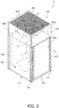
- FIG. 2 is an external perspective view of the outdoor unit 2.
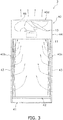
- FIG. 3 is a front view of the outdoor unit 2 (except the refrigerant circuit constituent components other than the outdoor heat exchanger 11).
- FIG. 4 is a schematic perspective view of the outdoor heat exchanger 11.
- FIG. 5 is a partial enlarged view of heat exchange sections 60A to 60F of FIG. 4 .
- FIG. 6 is a schematic configuration diagram of the outdoor heat exchanger 11.
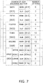
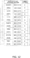
- FIG. 7 is a table listing a schematic configuration of the outdoor heat exchanger 11.
- FIG. 8 is an enlarged view near the lowermost heat exchange section (the first heat exchange section 60A) of FIG. 6 (illustrating the flow of the refrigerant in the heating operation).
- FIG. 9 is an enlarged view near the lowermost heat exchange section (the first heat exchange section 60A) of FIG. 6 (illustrating the flow of the refrigerant in the defrosting operation).
- the outdoor unit 2 is a top blow-out type heat exchange unit that sucks air from the side face of a casing 40 and blows out air from the top face of the casing 40.
- the outdoor unit 2 mainly includes the casing 40 having a substantially rectangular parallelepiped box shape, the outdoor fan 15 as a fan, the devices 7, 8, 11 including the compressor and the outdoor heat exchanger, and the refrigerant circuit constituent components which include the valves 10, and 12 to 14 having the four-way switching valve and the outdoor expansion valve and the refrigerant pipes 16 to 22 and constitute a part of the refrigerant circuit 6.
- the casing 40 mainly includes a bottom frame 42 which is put across a pair of installation legs 41 which extend in the right-left direction, supports 43 which extend in the vertical direction from corners of the bottom frame 42, a fan module 44 which is attached to the upper ends of the supports 43, and a front panel 45.
- the casing 40 includes inlet ports 40a, 40b, 40c for air on the side faces (in the present embodiment, the back face, and the right and left side faces) and a blow-out port 40d for air on the top face.
- the bottom frame 42 forms the bottom face of the casing 40.
- the outdoor heat exchanger 11 is disposed on the bottom frame 42.
- the outdoor heat exchanger 11 is a heat exchanger which has a substantially U shape in plan view and faces the back face and the right and left side faces of the casing 40.
- the outdoor heat exchanger 11 substantially forms the back face and the right and left side faces of the casing 40.
- the bottom frame 42 is in contact with a lower end part of the outdoor heat exchanger 11, and functions as a drain pan which receives drain water generated in the outdoor heat exchanger 11 in the cooling operation and the defrosting operation.
- the fan module 44 is disposed on the upper side of the outdoor heat exchanger 11 to form a part of the front face, the back face, and the right and left faces of the casing 40 above the supports 43 and the top face of the casing 40.
- the fan module 44 is an aggregate including a substantially rectangular parallelepiped box body whose upper and lower faces are open and the outdoor fan 15 housed in the box body. The opening on the top face of the fan module 44 corresponds to the blow-out port 40d.
- a blow-out grille 46 is disposed on the blow-out port 40d.
- the outdoor fan 15 is disposed facing the blow-out port 40d inside the casing 40.
- the outdoor fan 15 is a fan that takes air into the casing 40 through the inlet ports 40a, 40b, 40c and discharges air through the blow-out port 40d.
- the front panel 45 is put between the supports 43 on the front face side to form the front face of the casing 40.
- FIG. 2 illustrates the accumulator 7 and the compressor 8
- the compressor 8 and the accumulator 7 are disposed on the bottom frame 42.
- the outdoor unit 2 includes the casing 40 which includes the inlet ports 40a, 40b, 40c for air formed on the side faces (in the present embodiment, the back face and the right and left side faces) and the blow-out port 40d for air formed on the top face, the outdoor fan 15 which is disposed facing the blow-out port 40d inside the casing 40, and the outdoor heat exchanger 11 which is disposed below the outdoor fan 15 inside the casing 40.
- the outdoor heat exchanger 11 is a heat exchanger that exchanges heat between the refrigerant and outdoor air.
- the outdoor heat exchanger 11 mainly includes a first header collecting pipe 80, a second header collecting pipe 90, a plurality of flat pipes 63, and a plurality of fins 64.
- the first header collecting pipe 80, the second header collecting pipe 90, the flat pipes 63, and the fins 64 are all made of aluminum or an aluminum alloy and joined to each other by, for example, brazing.
- Each of the first header collecting pipe 80 and the second header collecting pipe 90 is a vertically oriented hollow cylindrical member whose upper and lower ends are closed.
- the first header collecting pipe 80 stands on one end side (in the present embodiment, on the left front end side in FIG. 4 or the left end side in FIG. 6 ) of the outdoor heat exchanger 11.
- the second header collecting pipe 90 stands on the other end side (in the present embodiment, the right front end side in FIG. 4 or the right end side in FIG. 6 ) of the outdoor heat exchanger 11.
- Each of the flat pipes 63 is a flat perforated pipe including a flat part 63a which serves as a heat transfer surface and faces in the vertical direction and a large number of small passages 63b through which the refrigerant flows, the passages 63b being formed inside the flat pipe 63.
- a plurality of flat pipes 63 are vertically arrayed. Both ends of each of the flat pipes 63 are connected to the first header collecting pipe 80 and the second header collecting pipe 90.
- the fins 64 partition a space between adjacent flat pipes 63 into a plurality of air flow passages through which air flows.
- Each of the fins 64 includes a plurality of cutouts 64a each of which horizontally extends long so that a plurality of flat pipes 63 can be inserted into the cutouts 64a.
- the shape of the cutout 64a of the fin 64 substantially coincides with the outer shape of the cross section of the flat pipe 63.
- the flat pipes 63 are divided into a plurality of heat exchange sections 60A to 60F (in the present embodiment, six heat exchange sections) which are vertically arranged side by side.
- a first heat exchange section 60A which is the lowermost heat exchange section
- a second heat exchange section 60B ...
- the first heat exchange section 60A includes twenty-one flat pipes 63 including the lowermost flat pipe 63A.
- the second heat exchange section 60B includes eighteen flat pipes 63.
- the third heat exchange section 60C includes fifteen flat pipes 63.
- the fourth heat exchange section 60D includes thirteen flat pipes 63.
- the fifth heat exchange section 60E includes eleven flat pipes 63.
- the sixth heat exchange section 60F includes nine flat pipes 63.
- An internal space of the first header collecting pipe 80 is vertically partitioned by partition plates 81 so that entrance communication spaces 82A to 82F respectively corresponding to the heat exchange sections 60A to 60F are formed. Further, each of the entrance communication spaces 82B to 82F except the first entrance communication space 82A corresponding to the first heat exchange section 60A is vertically partitioned into two spaces by a partition plate 83 so that upper gas-side entrance communication spaces 84B to 84F and lower liquid-side entrance communication spaces 85B to 85F are formed.
- the first entrance communication space 82A corresponding to the first heat exchange section 60A is vertically partitioned into three spaces by two partition plates 86 so that a first upper gas-side entrance communication space 84AU, a first liquid-side entrance communication space 85A, and a first lower gas-side entrance communication space 84AL are formed in that order from top to bottom.
- the first upper gas-side entrance communication space 84AU and the first lower gas-side entrance communication space 84AL are collectively defined as a first gas-side entrance communication spaces 84A.
- the second gas-side entrance communication space 84B communicates with top twelve of the flat pipes 63 constituting the second heat exchange section 60B.
- the second liquid-side entrance communication space 85B communicates with the remaining six of the flat pipes 63 constituting the second heat exchange section 60B.
- the third gas-side entrance communication space 84C communicates with top ten of the flat pipes 63 constituting the third heat exchange section 60C.
- the third liquid-side entrance communication space 85C communicates with the remaining five of the flat pipes 63 constituting the third heat exchange section 60C.
- the fourth gas-side entrance communication space 84D communicates with top nine of the flat pipes 63 constituting the fourth heat exchange section 60D.
- the fourth liquid-side entrance communication space 85D communicates with the remaining four of the flat pipes 63 constituting the fourth heat exchange section 60D.
- the fifth gas-side entrance communication space 84E communicates with top seven of the flat pipes 63 constituting the fifth heat exchange section 60E.
- the fifth liquid-side entrance communication space 85E communicates with the remaining four of the flat pipes 63 constituting the fifth heat exchange section 60E.
- the sixth gas-side entrance communication space 84F communicates with top six of the flat pipes 63 constituting the sixth heat exchange section 60F.
- the sixth liquid-side entrance communication space 85F communicates with the remaining three of the flat pipes 63 constituting the sixth heat exchange section 60F.
- the first upper gas-side entrance communication space 84AU communicates with top twelve of the flat pipes 63 constituting the first heat exchange section 60A.
- the first lower gas-side entrance communication space 84AL communicates with bottom two of the flat pipes 63 constituting the first heat exchange section 60A including the lowermost flat pipe 63A.
- the first liquid-side entrance communication space 85A communicates with the remaining seven of the flat pipes 63 constituting the first heat exchange section 60A.
- the flat pipes 63 communicating with the gas-side entrance communication spaces 84A to 84F are defined as main heat exchange sections 61A to 61F, and the flat pipes 63 communicating with the liquid-side entrance communication spaces 85A to 85F are defined as sub heat exchange sections 62A to 62F. More specifically, in the second entrance communication space 82B, the second gas-side entrance communication space 84B communicates with top twelve of the flat pipes 63 constituting the second heat exchange section 60B (the second main heat exchange section 61B), and the second liquid-side entrance communication space 85B communicates with the remaining six of the flat pipes 63 constituting the second heat exchange section 60B (the second sub heat exchange section 62B).
- the third gas-side entrance communication space 84C communicates with top ten of the flat pipes 63 constituting the third heat exchange section 60C (the third main heat exchange section 61C), and the third liquid-side entrance communication space 85C communicates with the remaining five of the flat pipes 63 constituting the third heat exchange section 60C (the third sub heat exchange section 62C).
- the fourth gas-side entrance communication space 84D communicates with top nine of the flat pipes 63 constituting the fourth heat exchange section 60D (the fourth main heat exchange section 61D), and the fourth liquid-side entrance communication space 85D communicates with the remaining four of the flat pipes 63 constituting the fourth heat exchange section 60D (the fourth sub heat exchange section 62D).
- the fifth gas-side entrance communication space 84E communicates with top seven of the flat pipes 63 constituting the fifth heat exchange section 60E (the fifth main heat exchange section 61E), and the fifth liquid-side entrance communication space 85E communicates with the remaining four of the flat pipes 63 constituting the fifth heat exchange section 60E (the fifth sub heat exchange section 62E).
- the sixth gas-side entrance communication space 84F communicates with top six of the flat pipes 63 constituting the sixth heat exchange section 60F (the sixth main heat exchange section 61F), and the sixth liquid-side entrance communication space 85F communicates with the remaining three of the flat pipes 63 constituting the sixth heat exchange section 60F (the sixth sub heat exchange section 62F).
- the first upper gas-side entrance communication space 84AU which is one of the first gas-side entrance communication spaces 84A, communicates with top twelve of the flat pipes 63 constituting the first heat exchange section 60A (a first upper main heat exchange section 61AU which is one of the first main heat exchange sections 61A).
- the first lower gas-side entrance communication space 84AL which is the other first gas-side entrance communication space 84A, communicates with bottom two of the flat pipes 63 constituting the first heat exchange section 60A (a first lower main heat exchange section 61AL which is the other first main heat exchange section 61A).
- the first liquid-side entrance communication space 85A communicates with the remaining seven of the flat pipes 63 constituting the first heat exchange section 60A (the first sub heat exchange section 62A).
- a liquid-side flow dividing member 70 which divides and feeds the refrigerant fed from the outdoor expansion valve 12 (refer to FIG. 1 ) into the liquid-side entrance communication spaces 85A to 85F in the heating operation and a gas-side flow dividing member 75 which divides and feeds the refrigerant fed from the compressor 8 (refer to FIG. 1 ) into the gas-side entrance communication spaces 84A to 84F in the cooling operation are connected to the first header collecting pipe 80.
- the liquid-side flow dividing member 70 includes a liquid-side refrigerant flow divider 71 which is connected to the refrigerant pipe 20 (refer to FIG. 1 ) and liquid-side refrigerant flow dividing pipes 72A to 72F which extend from the liquid-side refrigerant flow divider 71 and are connected to the liquid-side entrance communication spaces 85A to 85F, respectively.
- Each of the liquid-side refrigerant flow dividing pipes 72A to 72F includes a capillary tube and has a length and an inner diameter corresponding to a flow dividing ratio to each of the sub heat exchange sections 62A to 62F.
- the gas-side flow dividing member 75 includes a gas-side refrigerant flow dividing header pipe 76 which is connected to the refrigerant pipe 19 (refer to FIG. 1 ) and gas-side refrigerant flow dividing branch pipes 77A to 77F which extend from the gas-side refrigerant flow dividing header pipe 76 and are connected to the gas-side entrance communication spaces 84A to 84F, respectively.
- the first gas-side entrance communication space 84A includes the first upper gas-side entrance communication space 84AU and the first lower gas-side entrance communication space 84AL.
- the first gas-side refrigerant flow dividing branch pipe 77A extending from the gas-side refrigerant flow dividing header pipe 76 also includes a first upper gas-side refrigerant flow dividing branch pipe 77AU and a first lower gas-side refrigerant flow dividing branch pipe 77AL.
- An internal space of the second header collecting pipe 90 is vertically partitioned by partition plates 91 so that return communication spaces 92A to 92F respectively corresponding to the heat exchange sections 60A to 60F are formed. Further, the first return communication space 92A corresponding to the first heat exchange section 60A is vertically partitioned into two spaces by a partition plate 93 so that a first upper return communication space 92AU on the upper side and a first lower return communication space 92AL on the lower side are formed.
- the internal space of the second header collecting pipe 90 is not limited to the configuration merely partitioned by the partition plates 91, 93 as described above, and alternatively may have a configuration designed for satisfactorily maintaining a flow state of the refrigerant inside the second header collecting pipe 90.
- Each of the return communication spaces 92A to 92F communicates with all the flat pipes 63 constituting the corresponding one of the heat exchange sections 60A to 60F. More specifically, the second return communication space 92B communicates with all the eighteen flat pipes 63 constituting the second heat exchange section 60B. The third return communication space 92C communicates with all the fifteen flat pipes 63 constituting the third heat exchange section 60C. The fourth return communication space 92D communicates with all the thirteen flat pipes 63 constituting the fourth heat exchange section 60D. The fifth return communication space 92E communicates with all the eleven flat pipes 63 constituting the fifth heat exchange section 60E. The sixth return communication space 92F communicates with all the nine flat pipes 63 constituting the sixth heat exchange section 60F.
- the first return communication space 92A communicates with all the twenty-one flat pipes 63 constituting the first heat exchange section 60A.
- the first upper return communication space 92AU which is the upper part of the first return communication space 92A, communicates with top seventeen of the twenty-one flat pipes 63 constituting the first heat exchange section 60A.
- the first lower return communication space 92AL which is the lower part of the first return communication space 92A, communicates with bottom four of the twenty-one flat pipes 63 constituting the first heat exchange section 60A including the lowermost flat pipe 63A.
- top twelve of the seventeen flat pipes 63 communicating with the first upper return communication space 92AU constitute the first upper main heat exchange section 61AU which is one of the first main heat exchange sections 61A, and the remaining five flat pipes 63 constitute the first upper sub heat exchange section 62AU which is the upper part of the first sub heat exchange section 62A.
- bottom two of the four flat pipes 63 communicating with the first lower return communication space 92AL including the lowermost flat pipe 63A constitute the first lower main heat exchange section 61AL which is the other first main heat exchange section 61A, and the remaining two flat pipes 63 constitute the first lower sub heat exchange section 62AL which is the lower part of the first sub heat exchange section 62A.
- each of the heat exchange sections 60A to 60F includes the main heat exchange sections 61A to 61F and the sub heat exchange sections 62A to 62F which are connected in series to the main heat exchange sections 61A to 61F at vertical positions different from the main heat exchange sections 61A to 61F.
- the second heat exchange section 60B has a configuration in which the twelve flat pipes 63 constituting the second main heat exchange section 61B which communicates with the second gas-side entrance communication space 84B and the six flat pipes 63 constituting the second sub heat exchange section 62B which is located directly below the second main heat exchange section 61B and communicates with the second liquid-side entrance communication space 85B are connected in series through the second return communication space 92B.
- the third heat exchange section 60C has a configuration in which the ten flat pipes 63 constituting the third main heat exchange section 61C which communicates with the third gas-side entrance communication space 84C and the five flat pipes 63 constituting the third sub heat exchange section 62C which is located directly below the third main heat exchange section 61C and communicates with the third liquid-side entrance communication space 85C are connected in series through the third return communication space 92C.
- the fourth heat exchange section 60D has a configuration in which the nine flat pipes 63 constituting the fourth main heat exchange section 61D which communicates with the fourth gas-side entrance communication space 84D and the four flat pipes 63 constituting the fourth sub heat exchange section 62D which is located directly below the fourth main heat exchange section 61D and communicates with the fourth liquid-side entrance communication space 85D are connected in series through the fourth return communication space 92D.
- the fifth heat exchange section 60E has a configuration in which the seven flat pipes 63 constituting the fifth main heat exchange section 61E which communicates with the fifth gas-side entrance communication space 84E and the four flat pipes 63 constituting the fifth sub heat exchange section 62E which is located directly below the fifth main heat exchange section 61E and communicates with the fifth liquid-side entrance communication space 85E are connected in series through the fifth return communication space 92E.
- the sixth heat exchange section 60F has a configuration in which the six flat pipes 63 constituting the sixth main heat exchange section 61F which communicates with the sixth gas-side entrance communication space 84F and the three flat pipes 63 constituting the sixth sub heat exchange section 62F which is located directly below the sixth main heat exchange section 61F and communicates with the sixth liquid-side entrance communication space 85F are connected in series through the sixth return communication space 92F.
- the first heat exchange section 60A has a configuration in which the fourteen flat pipes 63 constituting the first main heat exchange section 61A which communicates with the first gas-side entrance communication space 84A and the seven flat pipes 63 constituting the first sub heat exchange section 62A which communicates with the first liquid-side entrance communication space 85A are connected in series through the first return communication space 92A.
- the first heat exchange section 60A includes the two upper and lower heat exchange sections 60AU, 60AL.
- the first upper heat exchange section AU has a configuration in which the twelve flat pipes 63 constituting the first upper main heat exchange section 61AU which communicates with the first upper gas-side entrance communication space 84AU and the five flat pipes 63 constituting the first upper sub heat exchange section 62AU which is located directly below the first upper main heat exchange section 61AU and communicates with the first liquid-side entrance communication space 85A are connected in series through the first upper return communication space 92AU.
- the first lower heat exchange section AL has a configuration in which the two flat pipes 63 constituting the first lower main heat exchange section 61AL which communicates with the first lower gas-side entrance communication space 84AL including the lowermost flat pipe 63A and the two flat pipes 63 constituting the first lower sub heat exchange section 62AL which is located directly above the first lower main heat exchange section 61AL and communicates with the first liquid-side entrance communication space 85A are connected in series through the first lower return communication space 92AL.
- the outdoor heat exchanger 11 includes the flat pipes 63 which are vertically arrayed, each of the flat pipes 63 including the passage 63b for the refrigerant formed inside thereof, and the fins 64 which partition a space between adjacent flat pipes 63 into a plurality of air flow passages through which air flows.
- the flat pipes 63 are divided into the heat exchange sections 60A to 60F.
- Each of the heat exchange sections 60A to 60F include the main heat exchange sections 61A to 61F and the sub heat exchange sections 62A to 62F which are connected in series to the main heat exchange sections 61A to 61F at vertical positions different from the main heat exchange sections 61A to 61F.
- the first main heat exchange section 61A of the first heat exchange section 60A including the lowermost flat pipe 63A among the heat exchange sections 60A to 60F is disposed so as to include the lowermost flat pipe 63A.
- the first sub heat exchange section 62A includes the first upper sub heat exchange section 62AU and the first lower sub heat exchange section 62AL which is located below the first upper sub heat exchange section 62AU.
- the first main heat exchange section 61A includes the first upper main heat exchange section 61AU which is connected to the first upper sub heat exchange section 62AU above the first upper sub heat exchange section 62AU and the first lower main heat exchange section 61AL which is connected to the first lower sub heat exchange section 62AL below the first lower sub heat exchange section 62AL.
- the ratio of the number of flat pipes 63 constituting the first lower main heat exchange section 61AL to the number of flat pipes 63 constituting the first lower sub heat exchange section 62AL is not limited to 1.0, but preferably within the range of 0.5 to 1.5.
- the ratio of the number of flat pipes 63 constituting the first upper main heat exchange section 61AU to the number of flat pipes 63 constituting the first upper sub heat exchange section 62AU is not limited to 2.4, but preferably within the range of 1.7 to 3.0.
- the heat exchange sections 60A to 60F are vertically arranged side by side, and, in the heat exchange sections 60B to 60F other than the first heat exchange section 60A, the sub heat exchange sections 62B to 62F are disposed below the main heat exchange sections 61B to 61F.
- the outdoor heat exchanger 11 functions as a radiator for the refrigerant discharged from the compressor 8 (refer to FIG. 1 ).
- the refrigerant discharged from the compressor 8 (refer to FIG. 1 ) is fed to the gas-side flow dividing member 75 through the refrigerant pipe 19 (refer to FIG. 1 ).
- the refrigerant fed to the gas-side flow dividing member 75 is divided into the gas-side refrigerant flow dividing branch pipes 77AU, 77AL, 77B to 77F from the gas-side refrigerant flow dividing header pipe 76 and fed to the gas-side entrance communication spaces 84AU, 84AL, 84B to 84F of the first header collecting pipe 80.
- the refrigerant fed to each of the gas-side entrance communication spaces 84AU, 84AL, 84B to 84F is divided into the flat pipes 63 constituting the main heat exchange sections 61AU, 61AL, 61B to 61F of the corresponding heat exchange sections 60AU, 60AL, 60B to 60F.
- the refrigerant fed to each flat pipe 63 dissipates heat by heat exchange with outdoor air while flowing through the passage 63b, and flows of the refrigerant merge with each other in each of the return communication spaces 92AU, 92AL, 92B to 92F of the second header collecting pipe 90. That is, the refrigerant passes through the main heat exchange sections 61AU, 61AL, 61B to 61F. At this time, the refrigerant dissipates heat until the refrigerant becomes a gas-liquid two-phase state or a liquid state close to a saturated state from a superheated gas state.
- the refrigerant merged in each of the return communication spaces 92AU, 92L, 92B to 92F is divided into the flat pipes 63 constituting the sub heat exchange sections 62AU, 62AL, 62B to 62F of the corresponding heat exchange sections 60AU, 60AL, 60B to 60F.
- the refrigerant fed to each flat pipe 63 dissipates heat by heat exchange with outdoor air while flowing through the passage 63b, and flows of the refrigerant merge with each other in each of the liquid-side entrance communication spaces 85A to 85F of the first header collecting pipe 80. That is, the refrigerant passes through the sub heat exchange sections 62AU, 62AL, 62B to 62F. At this time, the refrigerant further dissipates heat until the refrigerant becomes a subcooled liquid state from the gas-liquid two-phase state or the liquid state close to a saturated state.
- the refrigerant fed to the liquid-side entrance communication spaces 85A to 85F is fed to the liquid-side refrigerant flow dividing pipes 72A to 72F of the liquid-side refrigerant flow dividing member 70, and flows of the refrigerant merge with each other in the liquid-side refrigerant flow divider 71.
- the refrigerant merged in the liquid-side refrigerant flow divider 71 is fed to the outdoor expansion valve 12 (refer to FIG. 1 ) through the refrigerant pipe 20 (refer to FIG. 1 ).
- the outdoor heat exchanger 11 functions as an evaporator for the refrigerant decompressed by the outdoor expansion valve 12 (refer to FIG. 1 ).
- the refrigerant decompressed by the outdoor expansion valve 12 is fed to the liquid-side refrigerant flow dividing member 70 through the refrigerant pipe 20 (refer to FIG. 1 ).
- the refrigerant fed to the liquid-side refrigerant flow dividing member 70 is divided into the liquid-side refrigerant flow dividing pipes 72A to 72F from the liquid-side refrigerant flow divider 71 and fed to the liquid-side entrance communication spaces 85A to 85F of the first header collecting pipe 80.
- the refrigerant fed to each of the liquid-side entrance communication spaces 85A to 85F is divided into the flat pipes 63 constituting the sub heat exchange sections 62AU, 62AL, 62B to 62F of the corresponding heat exchange sections 60AU, 60AL, 60B to 60F.
- the refrigerant fed to each flat pipe 63 evaporates by heat exchange with outdoor air while flowing through the passage 63b, and flows of the refrigerant merge with each other in each of the return communication spaces 92AU, 92AL, 92B to 92F of the second header collecting pipe 90. That is, the refrigerant passes through the sub heat exchange sections 62AU, 62AL, 62B to 62F. At this time, the refrigerant evaporates until the refrigerant becomes a gas-liquid two-phase state having more gas components or a gas state close to a saturated state from a gas-liquid two-phase state having more liquid components.
- the refrigerant merged in each of the return communication spaces 92AU, 92AL, 92B to 92F is divided into the flat pipes 63 constituting the main heat exchange sections 61AU, 61AL, 61B to 61F of the corresponding heat exchange sections 60AU, 60AL, 60B to 60F.
- the refrigerant fed to each flat pipe 63 evaporates (is heated) by heat exchange with outdoor air while flowing through the passage 63b, and flows of the refrigerant merge with each other in each of the gas-side entrance communication spaces 84AU, 84AL, 84B to 84F of the first header collecting pipe 80. That is, the refrigerant passes through the main heat exchange sections 61AU, 61AL, 61B to 61F. At this time, the refrigerant further evaporates (is heated) until the refrigerant becomes a superheated gas state from the gas-liquid two-phase state having more gas components or the gas state close to a saturated state.
- the refrigerant fed to the gas-side entrance communication spaces 84AU, 84AL, 84B to 84F is fed to the gas-side refrigerant flow dividing branch pipes 77AU, 77AL, 77B to 77F of the gas-side refrigerant flow dividing member 75, and flows of the refrigerant merge with each other in the gas-side refrigerant flow dividing header pipe 76.
- the refrigerant merged in the gas-side refrigerant flow dividing header pipe 76 is fed to the suction side of the compressor 8 (refer to FIG. 1 ) through the refrigerant pipe 19 (refer to FIG. 1 ).
- the outdoor heat exchanger 11 functions as a radiator for the refrigerant discharged from the compressor 8 (refer to FIG. 1 ) in a manner similar to the cooling operation.
- the flow of the refrigerant in the outdoor heat exchanger 11 in the defrosting operation is similar to that in the cooling operation. Thus, description thereof will be omitted.
- the refrigerant mainly dissipates heat while melting frost adhered to the heat exchange sections 60AU, 60AL, 60B to 60F in the defrosting operation.
- the outdoor heat exchanger 11 (heat exchanger) of the present embodiment has characteristics as described below.
- the heat exchanger 11 of the present embodiment includes the flat pipes 63 which are vertically arrayed, each of the flat pipes 63 including the passage 63b for the refrigerant formed inside thereof, and the fins 64 which partition a space between adjacent flat pipes 63 into a plurality of air flow passages through which air flows.
- the flat pipes 63 are divided into the heat exchange sections 60A to 60F.
- Each of the heat exchange sections 60A to 60F include the main heat exchange sections 61A to 61F which are connected to the gas-side entrance communication spaces 84A to 84F, respectively, and the sub heat exchange sections 62A to 62F which are connected in series to the main heat exchange sections 61A to 61F at vertical positions different from the main heat exchange sections 61A to 61F and are connected to the liquid-side entrance communication spaces 85A to 85F, respectively.
- the first main heat exchange section 61A of the first heat exchange section 60A including the lowermost flat pipe 63A among the heat exchange sections 60A to 60F is disposed so as to include the lowermost flat pipe 63A.
- a plurality of flat pipes are divided into a plurality of heat exchange sections which are vertically arranged side by side, and each of the heat exchange sections includes a main heat exchange section and a sub heat exchange section which is connected in series to the main heat exchange section below the main heat exchange section.
- the sub heat exchange section of the lowermost one of the heat exchange sections is disposed so as to include the lowermost flat pipe (the flat pipe 63A in the present embodiment).
- the heating operation used as the evaporator for the refrigerant
- the defrosting operation used as the radiator for the refrigerant
- the refrigerant in a liquid state tends to be accumulated in the lowermost sub heat exchange section including the lowermost flat pipe.
- the defrosting operation is performed in such a condition, the refrigerant in a gas state first flows into the lowermost main heat exchange section and then flows into the lowermost sub heat exchange section.
- the lowermost sub heat exchange section including the lowermost flat pipe located on the downstream side in the refrigerant flow in the defrosting operation is one of the reasons why the time required for melting frost adhered to the lowermost heat exchange section becomes long in the defrosting operation.
- a flow rate of the refrigerant in a gas state flowing into the lowermost heat exchange section becomes lower than that in the upper heat exchange section due to the influence of a liquid head of the refrigerant, which increases the time required for melting frost adhered to the lowermost heat exchange section.
- the degree of the liquid head is affected by the height position of the flat pipe included in the sub heat exchange section of the heat exchange section.
- the liquid head of the refrigerant is large, and the flow rate of the refrigerant in a gas state flowing into the lowermost heat exchange section in the defrosting operation is further reduced. That is, it is assumed that, in the configuration of the conventional heat exchanger, a reduction in the flow rate of the refrigerant in a gas state flowing into the lowermost heat exchange section due to the liquid head of the refrigerant in the defrosting operation is one of the reasons why the time required for melting frost adhered to the lowermost heat exchange section becomes long in the defrosting operation.
- the lower end part of the fin close to the lowermost flat pipe is in contact with a drain pan (the bottom frame 42 in the present embodiment).
- a drain pan the bottom frame 42 in the present embodiment.
- the time required for melting frost adhered to the lowermost heat exchange section is longer than the time required for melting frost adhered to the heat exchange section located on the upper side relative to the lowermost heat exchange section because the lowermost sub heat exchange section includes the lowermost flat pipe.
- the first main heat exchange section 61A of the first heat exchange section 60A including the lowermost flat pipe 63A among the heat exchange sections 60A to 60F is disposed so as to include the lowermost flat pipe 63A.
- the heat exchanger 11 having such a configuration is employed in the air conditioner 1 which performs the heating operation and the defrosting operation in a switching manner, as illustrated in FIG. 8 , the refrigerant in a gas-liquid two-phase state flows into the first sub heat exchange section 62A, is heated while passing through the first sub heat exchange section 62A and the first main heat exchange section 61A including the lowermost flat pipe 63A in that order, and flows out of the first heat exchange section 60A in the heating operation (used as the evaporator for the refrigerant) when attention is paid to the first heat exchange section 60A. Further, in the defrosting operation (used as the radiator for the refrigerant), as illustrated in FIG.
- the refrigerant in a gas state flows into the first main heat exchange section 61A, is cooled while passing through the first main heat exchange section 61A including the lowermost flat pipe 63A and the first sub heat exchange section 62A in that order, and flows out of the first heat exchange section 60A. That is, in the present embodiment, the first main heat exchange section 61A including the lowermost flat pipe 63A is located on the upstream side in the refrigerant flow in the defrosting operation.
- the refrigerant in a gas state it is possible to allow the refrigerant in a gas state to flow into the first main heat exchange section 61A including the lowermost flat pipe 63A to actively heat and evaporate the refrigerant in a liquid state accumulated in the lowermost first sub heat exchange section 62A and promptly increase the temperature in the lowermost first heat exchange section 60A. Accordingly, it is possible to shorten the time required for melting frost adhered to the lowermost heat exchange section 63A in the defrosting operation as compared to the case where the conventional heat exchanger is employed.
- the first sub heat exchange section 62A includes the first upper sub heat exchange section 62AU and the first lower sub heat exchange section 62AL which is located below the first upper sub heat exchange section 62AU.
- the first main heat exchange section 61A includes the first upper main heat exchange section 61AU which is connected to the first upper sub heat exchange section 62AU above the first upper sub heat exchange section 62AU and the first lower main heat exchange section 61AL which is connected to the first lower sub heat exchange section 62AL below the first lower sub heat exchange section 62AL.
- the refrigerant in a gas-liquid two-phase state flows into the first upper sub heat exchange section 62AU and the first lower sub heat exchange section 62AL as illustrated in FIG. 8 in the heating operation (used as the evaporator for the refrigerant). Then, the refrigerant in a gas-liquid two-phase state flowing into the first upper sub heat exchange section 62AU is heated while passing through the first upper sub heat exchange section 62AU and the first upper main heat exchange section 61AU located above the first upper sub heat exchange section 62AU in that order, and flows out of the first heat exchange section 60A.
- the refrigerant in a gas-liquid two-phase state flowing into the first lower sub heat exchange section 62AL is heated while passing through the first lower sub heat exchange section 62AL and the first lower main heat exchange section 61AL located below the first lower sub heat exchange section 62AL in that order, and flows out of the first heat exchange section 60A. Further, in the defrosting operation (used as the radiator for the refrigerant), as illustrated in FIG. 9 , the refrigerant in a gas state flows into the first upper main heat exchange section 61AU and the first lower main heat exchange section 61AL.
- the refrigerant in a gas state flowing into the first upper main heat exchange section 61AU is cooled while passing through the first upper main heat exchange section 61AU and the first upper sub heat exchange section 62AU located below the first upper main heat exchange section 61AU in that order, and flows out of the first heat exchange section 60A.
- the refrigerant in a gas state flowing into the first lower main heat exchange section 61AL is cooled while passing through the first lower main heat exchange section 61AL and the first lower sub heat exchange section 62AL located above the first lower main heat exchange section 61AL in that order, and flows out of the first heat exchange section 60A.
- the ratio of the number of flat pipes 63 constituting the first lower main heat exchange section 61AL to the number of flat pipes 63 constituting the first lower sub heat exchange section 62AL is set smaller than the ratio of the number of flat pipes 63 constituting the first upper main heat exchange section 61AU to the number of flat pipes 63 constituting the first upper sub heat exchange section 62AU.
- the above configuration of ⁇ B> includes the first heat exchange section 60A in which the first upper sub heat exchange section 62AU is disposed below the first upper main heat exchange section 61AU, and the first lower main heat exchange section 61AL is disposed below the first lower sub heat exchange section 62AL.
- the first heat exchange section 60A in which the first upper sub heat exchange section 62AU is disposed below the first upper main heat exchange section 61AU, and the first lower main heat exchange section 61AL is disposed below the first lower sub heat exchange section 62AL.
- the first lower sub heat exchange section 62AL and the first lower main heat exchange section 61AL (the first lower heat exchange section 60AL) in the first heat exchange section 60A function as a so-called down flow type evaporator in which the refrigerant passes through the first lower sub heat exchange section 62AL and then passes through the first lower main heat exchange section 61AL disposed below the first lower sub heat exchange section 62AL in the heating operation (used as the evaporator for the refrigerant).
- the down flow type evaporator when a fluid in a gas-liquid two-phase state is divided when being fed downward, a drift of the fluid tends to occur.
- the refrigerant is divided when being fed downward from the flat pipes 63 constituting the first lower sub heat exchange section 62AL to the flat pipes 63 constituting the first lower main heat exchange section 61AL.
- the ratio of the number of flat pipes 63 constituting the first lower main heat exchange section 61AL to the number of flat pipes 63 constituting the first lower sub heat exchange section 62AL increases, the possibility of the occurrence of a drift of the refrigerant increases.
- the ratio of the number of flat pipes 63 constituting the first lower main heat exchange section 61AL to the number of flat pipes 63 constituting the first lower sub heat exchange section 62AL is set smaller than the ratio of the number of flat pipes 63 constituting the first upper main heat exchange section 61AU to the number of flat pipes 63 constituting the first upper sub heat exchange section 62AU in the first heat exchange section 60A.
- the refrigerant when the refrigerant is fed downward from the flat pipes 63 constituting the first lower sub heat exchange section 62AL to the flat pipes 63 constituting the first lower main heat exchange section 61AU in the heating operation (used as the evaporator for the refrigerant), it is possible to suppress a drift of the refrigerant caused by the division of the refrigerant.
- the heat exchange sections 60A to 60F are vertically arranged side by side. Further, in the heat exchange sections 60B to 60F other than the first heat exchange section 60A, the sub heat exchange sections 62B to 62F are disposed below the main heat exchange sections 61B to 61F.
- the refrigerant in a gas-liquid two-phase state flows into the sub heat exchange sections 62B to 62F, is heated while passing through the sub heat exchange sections 62B to 62F and the main heat exchange sections 61B to 61F located above the sub heat exchange sections 62B to 62F in that order, and flows out of the heat exchange sections 60B to 60F in the heating operation (used as the evaporator for the refrigerant).
- the refrigerant in a gas state flows into the main heat exchange sections 61B to 61F, is cooled while passing through the main heat exchange sections 61B to 61F and the sub heat exchange sections 62B to 62F located below the main heat exchange sections 61B to 61F in that order, and flows out of the heat exchange sections 60B to 60F.
- the configuration in which the main heat exchange section 61A is disposed so as to include the lowermost flat pipe 63A in the lowermost first heat exchange section 60A including the lowermost flat pipe 63A is achieved by dividing the first heat exchange section 60A into the first upper heat exchange section 60AU and the first lower heat exchange section 60AL in which the first lower main heat exchange section 61AL is disposed so as to include the lowermost flat pipe 63A (refer to FIGS. 6 to 9 ).
- This configuration is obtained by disposing the two partition plates 86 on the first header collecting pipe 80 so as to partition the first entrance communication space 82A corresponding to the first heat exchange section 60A into the three entrance communication spaces 84AU, 85A, 84AL and disposing the partition plate 93 on the second header collecting pipe 90 so as to partition the first return communication space 92A corresponding to the first heat exchange section 60A into the two return communication spaces 92AU, 92AL.
- the first liquid-side entrance communication space 85A is a liquid-side entrance communication space common between the first upper heat exchange section 60AU and the first lower heat exchange section 60AL. In this point, the first upper heat exchange section 60AU and the first lower heat exchange section 60AL are not independent of each other.
- the configuration in which the main heat exchange section 61A is disposed so as to include the lowermost flat pipe 63A in the lowermost first heat exchange section 60A including the lowermost flat pipe 63A is not limited to the above configuration.
- the first header collecting pipe 80 may further include a partition plate that vertically partitions the first liquid-side entrance communication space 85A into two spaces to form two liquid-side entrance communication spaces so that the first upper heat exchange section 60AU and the first lower heat exchange section 60AL are independent of each other.
- a plurality of flat pipes 63 are divided into a plurality of heat exchange sections 60A to 60G (in the present modification, seven heat exchange sections) which are vertically arranged side by side.
- the first heat exchange section 60A which is the lowermost heat exchange section, the second heat exchange section 60B, ..., the sixth heat exchange section 60F, and the seventh heat exchange section 60G are formed in that order from bottom to top.
- the first heat exchange section 60A includes four flat pipes 63 including the lowermost flat pipe 63A.
- the second heat exchange section 60B includes seventeen flat pipes 63.
- the third heat exchange section 60C includes eighteen flat pipes 63.
- the fourth heat exchange section 60D includes fifteen flat pipes 63.
- the fifth heat exchange section 60E includes thirteen flat pipes 63.
- the sixth heat exchange section 60F includes eleven flat pipes 63.
- the seventh heat exchange section 60G includes nine flat pipes 63.
- An internal space of the first header collecting pipe 80 is vertically partitioned by a partition plate 81 so that entrance communication spaces 82A to 82G respectively corresponding to the heat exchange sections 60A to 60G are formed. Further, each of the entrance communication spaces 82A to 82G is vertically partitioned into two spaces by a partition plate 83. Accordingly, upper gas-side entrance communication spaces 84B to 84G and lower liquid-side entrance communication spaces 85B to 85G are formed in the entrance communication spaces 82B to 82G except the first entrance communication space 82A corresponding to the first heat exchange section 60A. An upper first liquid-side entrance communication space 85A and a lower first gas-side entrance communication space 84A are formed in the first entrance communication space 82A corresponding to the first heat exchange section 60A.
- the second gas-side entrance communication space 84B communicates with top twelve of the flat pipes 63 constituting the second heat exchange section 60B.
- the second liquid-side entrance communication space 85B communicates with the remaining five of the flat pipes 63 constituting the second heat exchange section 60B.
- the third gas-side entrance communication space 84C communicates with top twelve of the flat pipes 63 constituting the third heat exchange section 60C.
- the third liquid-side entrance communication space 85C communicates with the remaining six of the flat pipes 63 constituting the third heat exchange section 60C.
- the fourth gas-side entrance communication space 84D communicates with top ten of the flat pipes 63 constituting the fourth heat exchange section 60D.
- the fourth liquid-side entrance communication space 85D communicates with the remaining five of the flat pipes 63 constituting the fourth heat exchange section 60D.
- the fifth gas-side entrance communication space 84E communicates with top nine of the flat pipes 63 constituting the fifth heat exchange section 60E.
- the fifth liquid-side entrance communication space 85E communicates with the remaining four of the flat pipes 63 constituting the fifth heat exchange section 60E.
- the sixth gas-side entrance communication space 84F communicates with top seven of the flat pipes 63 constituting the sixth heat exchange section 60F.
- the sixth liquid-side entrance communication space 85F communicates with the remaining four of the flat pipes 63 constituting the sixth heat exchange section 60F.
- the seventh gas-side entrance communication space 84G communicates with top six of the flat pipes 63 constituting the seventh heat exchange section 60G.
- the seventh liquid-side entrance communication space 85G communicates with the remaining three of the flat pipes 63 constituting the seventh heat exchange section 60G.
- the first gas-side entrance communication space 84A communicates with bottom two of the flat pipes 63 constituting the first heat exchange section 60A including the lowermost flat pipe 63A.
- the first liquid-side entrance communication space 85A communicates with the remaining two of the flat pipes 63 constituting the first heat exchange section 60A.
- the flat pipes 63 communicating with the gas-side entrance communication spaces 84A to 84G are defined as main heat exchange sections 61A to 61G, and the flat pipes 63 communicating with the liquid-side entrance communication spaces 85A to 85G are defined as sub heat exchange sections 62A to 62G. More specifically, in the second entrance communication space 82B, the second gas-side entrance communication space 84B communicates with top twelve of the flat pipes 63 constituting the second heat exchange section 60B (the second main heat exchange section 61B), and the second liquid-side entrance communication space 85B communicates with the remaining five of the flat pipes 63 constituting the second heat exchange section 60B (the second sub heat exchange section 62B).
- the third gas-side entrance communication space 84C communicates with top twelve of the flat pipes 63 constituting the third heat exchange section 60C (the third main heat exchange section 61C), and the third liquid-side entrance communication space 85C communicates with the remaining six of the flat pipes 63 constituting the third heat exchange section 60C (the third sub heat exchange section 62C).
- the fourth gas-side entrance communication space 84D communicates with top ten of the flat pipes 63 constituting the fourth heat exchange section 60D (the fourth main heat exchange section 61D), and the fourth liquid-side entrance communication space 85D communicates with the remaining five of the flat pipes 63 constituting the fourth heat exchange section 60D (the fourth sub heat exchange section 62D).
- the fifth gas-side entrance communication space 84E communicates with top nine of the flat pipes 63 constituting the fifth heat exchange section 60E (the fifth main heat exchange section 61E), and the fifth liquid-side entrance communication space 85E communicates with the remaining four of the flat pipes 63 constituting the fifth heat exchange section 60E (the fifth sub heat exchange section 62E).
- the sixth gas-side entrance communication space 84F communicates with top seven of the flat pipes 63 constituting the sixth heat exchange section 60F (the sixth main heat exchange section 61F), and the sixth liquid-side entrance communication space 85F communicates with the remaining four of the flat pipes 63 constituting the fifth heat exchange section 60F (the sixth sub heat exchange section 62F).
- the seventh gas-side entrance communication space 84G communicates with top six of the flat pipes 63 constituting the seventh heat exchange section 60G (the seventh main heat exchange section 61G), and the seventh liquid-side entrance communication space 85G communicates with the remaining three of the flat pipes 63 constituting the seventh heat exchange section 60G (the seventh sub heat exchange section 62G).
- the first gas-side entrance communication space 84A communicates with bottom two of the flat pipes 63 constituting the first heat exchange section 60A including the lowermost flat pipe 63A (the first main heat exchange section 61A), and the first liquid-side entrance communication space 85A communicates with the remaining two of the flat pipes 63 constituting the first heat exchange section 60A (the first sub heat exchange section 62A).
- a liquid-side flow dividing member 70 which divides and feeds the refrigerant fed from the outdoor expansion valve 12 (refer to FIG. 1 ) into the liquid-side entrance communication spaces 85A to 85G in the heating operation and a gas-side flow dividing member 75 which divides and feeds the refrigerant fed from the compressor 8 (refer to FIG. 1 ) into the gas-side entrance communication spaces 84A to 84G in the cooling operation are connected to the first header collecting pipe 80.
- the liquid-side flow dividing member 70 includes a liquid-side refrigerant flow divider 71 which is connected to the refrigerant pipe 20 (refer to FIG. 1 ) and liquid-side refrigerant flow dividing pipes 72A to 72G which extend from the liquid-side refrigerant flow divider 71 and are connected to the liquid-side entrance communication spaces 85A to 85G, respectively.
- Each of the liquid-side refrigerant flow dividing pipes 72A to 72G includes a capillary tube and has a length and an inner diameter corresponding to a flow dividing ratio to each of the sub heat exchange sections 62A to 62G.
- the gas-side flow dividing member 75 includes a gas-side refrigerant flow dividing header pipe 76 which is connected to the refrigerant pipe 19 (refer to FIG. 1 ) and gas-side refrigerant flow dividing branch pipes 77A to 77G which extend from the gas-side refrigerant flow dividing header pipe 76 and are connected to the gas-side entrance communication spaces 84A to 84G, respectively.
- An internal space of the second header collecting pipe 90 is vertically partitioned by partition plates 91 so that return communication spaces 92A to 92G respectively corresponding to the heat exchange sections 60A to 60G are formed.
- the internal space of the second header collecting pipe 90 is not limited to the configuration merely partitioned by the partition plates 91 as described above, and alternatively may have a configuration designed for satisfactorily maintaining a flow state of the refrigerant inside the second header collecting pipe 90.
- Each of the return communication spaces 92A to 92G communicates with all the flat pipes 63 constituting the corresponding one of the heat exchange sections 60A to 60G. More specifically, the second return communication space 92B communicates with all the seventeen flat pipes 63 constituting the second heat exchange section 60B.
- the third return communication space 92C communicates with all the eighteen flat pipes 63 constituting the third heat exchange section 60C.
- the fourth return communication space 92D communicates with all the fifteen flat pipes 63 constituting the fourth heat exchange section 60D.
- the fifth return communication space 92E communicates with all the thirteen flat pipes 63 constituting the fifth heat exchange section 60E.
- the sixth return communication space 92F communicates with all the eleven flat pipes 63 constituting the sixth heat exchange section 60F.
- the seventh return communication space 92G communicates with all the nine flat pipes 63 constituting the seventh heat exchange section 60G.
- the first return communication space 92A communicates with all the four flat pipes 63 constituting the first heat exchange section 60A including the lowermost flat pipe 63A.
- each of the heat exchange sections 60A to 60G include the main heat exchange sections 61A to 61G and the sub heat exchange sections 62A to 62G which are connected in series to the main heat exchange sections 61A to 61G at vertical positions different from the main heat exchange sections 61A to 61G.
- the second heat exchange section 60B has a configuration in which the twelve flat pipes 63 constituting the second main heat exchange section 61B which communicates with the second gas-side entrance communication space 84B and the five flat pipes 63 constituting the second sub heat exchange section 62B which is located directly below the second main heat exchange section 61B and communicates with the second liquid-side entrance communication space 85B are connected in series through the second return communication space 92B.
- the third heat exchange section 60C has a configuration in which the twelve flat pipes 63 constituting the third main heat exchange section 61C which communicates with the third gas-side entrance communication space 84C and the six flat pipes 63 constituting the third sub heat exchange section 62C which is located directly below the third main heat exchange section 61C and communicates with the third liquid-side entrance communication space 85C are connected in series through the third return communication space 92C.
- the fourth heat exchange section 60D has a configuration in which the ten flat pipes 63 constituting the fourth main heat exchange section 61D which communicates with the fourth gas-side entrance communication space 84D and the five flat pipes 63 constituting the fourth sub heat exchange section 62D which is located directly below the fourth main heat exchange section 61D and communicates with the fourth liquid-side entrance communication space 85D are connected in series through the fourth return communication space 92D.
- the fifth heat exchange section 60E has a configuration in which the nine flat pipes 63 constituting the fifth main heat exchange section 61E which communicates with the fifth gas-side entrance communication space 84E and the four flat pipes 63 constituting the fifth sub heat exchange section 62E which is located directly below the fifth main heat exchange section 61E and communicates with the fifth liquid-side entrance communication space 85E are connected in series through the fifth return communication space 92E.
- the sixth heat exchange section 60F has a configuration in which the seven flat pipes 63 constituting the sixth main heat exchange section 61F which communicates with the sixth gas-side entrance communication space 84F and the four flat pipes 63 constituting the sixth sub heat exchange section 62F which is located directly below the sixth main heat exchange section 61F and communicates with the sixth liquid-side entrance communication space 85F are connected in series through the sixth return communication space 92F.
- the seventh heat exchange section 60G has a configuration in which the six flat pipes 63 constituting the seventh main heat exchange section 61G which communicates with the seventh gas-side entrance communication space 84G and the three flat pipes 63 constituting the seventh sub heat exchange section 62G which is located directly below the seventh main heat exchange section 61G and communicates with the seventh liquid-side entrance communication space 85G are connected in series through the seventh return communication space 92G.
- the first heat exchange section 60A has a configuration in which the two flat pipes 63 constituting the first main heat exchange section 61A which communicates with the first gas-side entrance communication space 84A including the lowermost flat pipe 63A and the two flat pipes 63 constituting the first sub heat exchange section 62A which is located directly above the first main heat exchange section 61A and communicates with the first liquid-side entrance communication space 85A are connected in series through the first return communication space 92A.
- the heat exchanger 11 includes the flat pipes 63 which are vertically arrayed, each of the flat pipes 63 including the passage 63b for the refrigerant formed inside thereof, and the fins 64 which partition a space between adjacent flat pipes 63 into a plurality of air flow passages through which air flows in a manner similar to the above embodiment.
- the flat pipes 63 are divided into the heat exchange sections 60A to 60G.
- Each of the heat exchange sections 60A to 60G include the main heat exchange sections 61A to 61G and the sub heat exchange sections 62A to 62G which are connected in series to the main heat exchange sections 61A to 61G at vertical positions different from the main heat exchange sections 61A to 61G.
- the first main heat exchange section 61A of the first heat exchange section 60A including the lowermost flat pipe 63A among the heat exchange sections 60A to 60G is disposed so as to include the lowermost flat pipe 63A.
- the time required for melting frost adhered to the lowermost heat exchange section 60A can be shortened in the defrosting operation in a manner similar to the above embodiment.
- all the heat exchange sections 60B to 60G other than the first heat exchange section 60A are disposed above the first heat exchange section 60A. Further, in the first heat exchange section 60A, the first main heat exchange section 61A is disposed below the first sub heat exchange section 62A.
- the refrigerant in a gas-liquid two-phase state flows into the first sub heat exchange section 62A, is heated while passing through the first sub heat exchange section 62A and the first main heat exchange section 61A located below the first sub heat exchange section 62A in that order, and flows out of the first heat exchange section 60A in the heating operation (used as the evaporator for the refrigerant). Further, in the defrosting operation (used as the radiator for the refrigerant), as illustrated in FIG.
- the refrigerant in a gas state flows into the first main heat exchange section 61A, is cooled while passing through the first main heat exchange section 61A and the first sub heat exchange section 62A located above the first main heat exchange section 61A in that order, and flows out of the first heat exchange section 60A.
- the above configuration provides the first heat exchange section 60A in which the first main heat exchange section 61A is disposed below the first sub heat exchange section 62A.
- the first heat exchange section 60A functions as a so-called down flow type evaporator in which the refrigerant passes through the first sub heat exchange section 62A and then passes through the first main heat exchange section 61A disposed below the first sub heat exchange section 62A in the heating operation (used as the evaporator for the refrigerant).
- the refrigerant is divided when being fed downward from the flat pipes 63 constituting the first sub heat exchange section 62A to the flat pipes 63 constituting the first main heat exchange section 61A.
- the ratio of the number of flat pipes 63 constituting the first main heat exchange section 61A to the number of flat pipes 63 constituting the first sub heat exchange section 62A increases, the possibility of the occurrence of a drift of the refrigerant increases.
- the ratio of the number of flat pipes 63 constituting the first main heat exchange section 61A to the number of flat pipes 63 constituting the first sub heat exchange section 62A is not limited to 1.0, but preferably within the range of 0.5 to 1.5. Further, the ratio of the number of flat pipes 63 constituting each of the other main heat exchange sections 61B to 61G to the number of flat pipes 63 constituting each of the other sub heat exchange sections 62B to 62G is not limited to 1.8 to 2.4, but preferably within the range of 1.7 to 3.0.
- the refrigerant when the refrigerant is fed downward from the flat pipes 63 constituting the first sub heat exchange section 62A to the flat pipes 63 constituting the first main heat exchange section 61A in the heating operation (used as the evaporator for the refrigerant), it is possible to suppress a drift of the refrigerant caused by the division of the refrigerant in a manner similar to the above embodiment.
- the present invention is applied to the outdoor heat exchanger 11 including six or seven heat exchange sections.
- the present invention is not limited thereto.
- the number of heat exchange sections may be less than six or more than seven.
- the number of flat pipes 63 constituting each of the heat exchange sections 60A to 60G and the ratio between the number of flat pipes 63 of each of the main heat exchange sections 61A to 61G and the number of flat pipes 63 of each of the sub heat exchange sections 62A to 62G in each of the heat exchange sections 60A to 60G are not limited to the number and the ratio in the above embodiment and the modification ⁇ A>.
- the present invention is applied to the outdoor heat exchanger 11 disposed on the top blow-out type outdoor unit 2.
- the present invention may be applied to an outdoor heat exchanger disposed on an outdoor unit of another type.
- the present invention is widely applicable to a heat exchanger including a plurality of flat pipes vertically arrayed, each of the flat pipes including a passage for a refrigerant formed inside thereof, and a plurality of fins that partition a space between adjacent flat pipes into a plurality of air flow passages through which air flows.
- Patent Literature 1 JP 2012-163313 A
Landscapes
- Engineering & Computer Science (AREA)
- Physics & Mathematics (AREA)
- Thermal Sciences (AREA)
- Mechanical Engineering (AREA)
- General Engineering & Computer Science (AREA)
- Heat-Exchange Devices With Radiators And Conduit Assemblies (AREA)
- Other Air-Conditioning Systems (AREA)
Abstract
Description
- The present invention relates to a heat exchanger. In particular, the present invention relates to a heat exchanger including a plurality of flat pipes vertically arrayed, each of the flat pipes including a passage for a refrigerant formed inside thereof, and a plurality of fins that partition a space between adjacent flat pipes into a plurality of air flow passages through which air flows.
- In a conventional technique, a heat exchanger including a plurality of flat pipes vertically arrayed and a plurality of fins that partition a space between adjacent flat pipes into a plurality of air flow passages through which air flows may be employed as a heat exchanger housed in an outdoor unit (heat exchange unit) of an air conditioner. Further, for example, such a heat exchanger includes a heat exchanger as described in Patent Literature 1 (
JP 2012-163313 A - The above conventional heat exchanger may be employed in an air conditioner that performs a heating operation and a defrosting operation in a switching manner. When the air conditioner performs the heating operation, the above conventional heat exchanger is used as an evaporator for a refrigerant. When the air conditioner performs the defrosting operation, the above conventional heat exchanger is used as a radiator for the refrigerant. Specifically, when the above conventional heat exchanger is used as the evaporator for the refrigerant, the refrigerant in a gas-liquid two-phase state is divided and flows into the sub heat exchange section included in each heat exchange section, is heated while passing through the sub heat exchange section and the main heat exchange section in that order, and flows out of the heat exchange section. Then, flows of the refrigerant merge with each other. Further, when the above conventional heat exchanger is used as the radiator for the refrigerant, the refrigerant in a gas state is divided and flows into the main heat exchange section of each heat exchange section, is cooled while passing through the main heat exchange section and the sub heat exchange section in that order, and flows out of the heat exchange section. Then, flows of the refrigerant merge with each other.
- However, in the air conditioner that employs the above conventional heat exchanger, the time required for melting frost adhered to the lowermost heat exchange section tends to become longer than the time required for melting frost adhered to the heat exchange section located on the upper side relative to the lowermost heat exchange section in the defrosting operation. Thus, frost may remain unmelted in the lowermost heat exchange section even after the defrosting operation, which may result in insufficient defrosting. Further, it is necessary to increase the time of the defrosting operation in order to suppress frost from remaining unmelted in the lowermost heat exchange section.
- It is an object of the present invention to shorten the time required for melting frost adhered to the lowermost heat exchange section in a defrosting operation when a heat exchanger including a plurality of flat pipes vertically arrayed, each of the flat pipes including a passage for a refrigerant formed inside of the flat pipe, and a plurality of fins that partition a space between each adjacent two of the flat pipes into a plurality of air flow passages through which air flows is employed in an air conditioner that performs a heating operation and a defrosting operation in a switching manner.
- A heat exchanger according to a first aspect includes a plurality of flat pipes vertically arrayed, each of the flat pipes including a passage for a refrigerant formed inside of the flat pipe; and a plurality of fins that partition a space between each adjacent two of the flat pipes into a plurality of air flow passages through which air flows. The flat pipes are divided into a plurality of heat exchange sections, and each of the heat exchange sections includes a main heat exchange section connected to a gas-side entrance communication space and a sub heat exchange section connected in series to the main heat exchange section at a vertical position different from the main heat exchange section and connected to a liquid-side entrance communication space. Further, when one of the heat exchange sections including a lowermost one of the flat pipes is defined as a first heat exchange section, and the main heat exchange section and the sub heat exchange section that constitute the first heat exchange section are defined as a first main heat exchange section and a first sub heat exchange section, the first main heat exchange section is disposed so as to include the lowermost flat pipe.
- First, the reason why the time required for melting frost adhered to the lowermost heat exchange section tends to become longer than the time required for melting frost adhered to the heat exchange section located on the upper side relative to the lowermost heat exchange section in the defrosting operation when the above conventional heat exchanger is employed in an air conditioner that performs the heating operation and the defrosting operation in a switching manner will be described.
- In the above conventional heat exchanger, a plurality of flat pipes are divided into a plurality of heat exchange sections which are vertically arranged side by side, and each of the heat exchange sections includes a main heat exchange section and a sub heat exchange section which is connected in series to the main heat exchange section below the main heat exchange section. Thus, in the above conventional heat exchanger, the sub heat exchange section of the lowermost one of the heat exchange sections is disposed so as to include the lowermost flat pipe.
- In the conventional configuration, when the heating operation (used as the evaporator for the refrigerant) is switched to the defrosting operation (used as the radiator for the refrigerant), the refrigerant in a liquid state tends to be accumulated in the lowermost sub heat exchange section including the lowermost flat pipe. Further, when the defrosting operation is performed in such a condition, the refrigerant in a gas state first flows into the lowermost main heat exchange section and then flows into the lowermost sub heat exchange section. Thus, it takes long time to evaporate the refrigerant in a liquid state accumulated in the lowermost sub heat exchange section. That is, it is assumed that, in the configuration of the conventional heat exchanger, the lowermost sub heat exchange section including the lowermost flat pipe located on the downstream side in the refrigerant flow in the defrosting operation is one of the reasons why the time required for melting frost adhered to the lowermost heat exchange section becomes long in the defrosting operation.
- Further, in this configuration, when the refrigerant in a gas state is divided and flows into the main heat exchange section of each heat exchange section in the defrosting operation, a flow rate of the refrigerant in a gas state flowing into the lowermost heat exchange section becomes lower than that in the upper heat exchange section due to the influence of a liquid head of the refrigerant, which increases the time required for melting frost adhered to the lowermost heat exchange section. The degree of the liquid head is affected by the height position of the flat pipe included in the sub heat exchange section of the heat exchange section. Thus, when the lowermost sub heat exchange section includes the lowermost flat pipe, the liquid head of the refrigerant is large, and the flow rate of the refrigerant in a gas state flowing into the lowermost heat exchange section in the defrosting operation is further reduced. That is, it is assumed that, in the configuration of the conventional heat exchanger, a reduction in the flow rate of the refrigerant in a gas state flowing into the lowermost heat exchange section due to the liquid head of the refrigerant in the defrosting operation is one of the reasons why the time required for melting frost adhered to the lowermost heat exchange section becomes long in the defrosting operation.
- Further, in the conventional configuration, the lower end part of the fin close to the lowermost flat pipe is in contact with a drain pan. Thus, heat dissipation from the lowermost sub heat exchange section including the lowermost flat pipe to the drain pan tends to occur. When the defrosting operation is performed in such a condition, heat dissipation from the lowermost sub heat exchange section to the drain pan hinders a temperature rise in the lowermost heat exchange section as compared to the upper heat exchange section, which increases the time required for melting frost adhered to the lowermost heat exchange section. That is, it is assumed that, in the configuration of the conventional heat exchanger, heat dissipation from the lowermost sub heat exchange section including the lowermost flat pipe to the drain pan is one of the reasons why the time required for melting frost adhered to the lowermost heat exchange section becomes long in the defrosting operation.
- In this manner, it is assumed that, in the conventional heat exchanger, when the heat exchanger is employed in the air conditioner that performs the heating operation and the defrosting operation in a switching manner, the time required for melting frost adhered to the lowermost heat exchange section is longer than the time required for melting frost adhered to the heat exchange section located on the upper side relative to the lowermost heat exchange section because the lowermost sub heat exchange section includes the lowermost flat pipe.
- Thus, in the first aspect, differently from the conventional heat exchanger, as described above, the first main heat exchange section of the first heat exchange section including the lowermost flat pipe among the heat exchange sections is disposed so as to include the lowermost flat pipe.
- Further, when the heat exchanger having such a configuration is employed in the air conditioner that performs the heating operation and the defrosting operation in a switching manner, the refrigerant in a gas-liquid two-phase state flows into the first sub heat exchange section, is heated while passing through the first sub heat exchange section and the first main heat exchange section including the lowermost flat pipe in that order, and flows out of the first heat exchange section in the heating operation (used as the evaporator for the refrigerant) when attention is paid to the first heat exchange section. Further, in the defrosting operation (used as the radiator for the refrigerant), the refrigerant in a gas state flows into the first main heat exchange section, is cooled while passing through the first main heat exchange section including the lowermost flat pipe and the first sub heat exchange section in that order, and flows out of the first heat exchange section. That is, in the first aspect, the first main heat exchange section including the lowermost flat pipe is located on the upstream side in the refrigerant flow in the defrosting operation. Thus, in the first aspect, it is possible to allow the refrigerant in a gas state to flow into the first main heat exchange section including the lowermost flat pipe to actively heat and evaporate the refrigerant in a liquid state accumulated in the lowermost first sub heat exchange section and promptly increase the temperature in the lowermost first heat exchange section. Accordingly, in the first aspect, it is possible shorten the time required for melting frost adhered to the lowermost heat exchange section in the defrosting operation as compared to the case where the conventional heat exchanger is employed.
- In this manner, in the first aspect, it is possible to shorten the time required for melting frost adhered to the lowermost heat exchange section in the defrosting operation by employing the heat exchanger having the above configuration in the air conditioner that performs the heating operation and the defrosting operation in a switching manner.
- A heat exchanger according to a second aspect is the heat exchanger according to the first aspect in which all the heat exchange sections other than the first heat exchange section are disposed above the first heat exchange section. Further, the first main heat exchange section is disposed below the first sub heat exchange section in the first heat exchange section.
- When the heat exchanger having such a configuration is employed in the air conditioner that performs the heating operation and the defrosting operation in a switching manner, the refrigerant in a gas-liquid two-phase state flows into the first sub heat exchange section, is heated while passing through the first sub heat exchange section and the first main heat exchange section located below the first sub heat exchange section in that order, and flows out of the first heat exchange section in the heating operation (used as the evaporator for the refrigerant) when attention is paid to the first heat exchange section. Further, in the defrosting operation (used as the radiator for the refrigerant), the refrigerant in a gas state flows into the first main heat exchange section, is cooled while passing through the first main heat exchange section and the first sub heat exchange section located above the first main heat exchange section in that order, and flows out of the first heat exchange section.
- A heat exchanger according to a third aspect is the heat exchanger according to the second aspect in which a ratio of a number of the flat pipes constituting the first main heat exchange section to a number of the flat pipes constituting the first sub heat exchange section is set smaller than a ratio of a number of the flat pipes constituting the main heat exchange section to a number of the flat pipes constituting the sub heat exchange section in the other heat exchange sections.
- As described above, the heat exchanger according to the second aspect includes the first heat exchange section in which the first main heat exchange section is disposed below the first sub heat exchange section. Thus, when the heat exchanger according to the second aspect is employed in the air conditioner that performs the heating operation and the defrosting operation in a switching manner, the first heat exchange section functions as a so-called down flow type evaporator in which the refrigerant passes through the first sub heat exchange section and then passes through the first main heat exchange section disposed below the first sub heat exchange section in the heating operation (used as the evaporator for the refrigerant). In the down flow type evaporator, when a fluid in a gas-liquid two-phase state is divided when being fed downward, a drift of the fluid tends to occur. Also in the first heat exchange section, the refrigerant is divided when being fed downward from the flat pipes constituting the first sub heat exchange section to the flat pipes constituting the first main heat exchange section. Thus, there is a possibility that a drift of the refrigerant occurs. At this time, when the ratio of the number of the flat pipes constituting the first main heat exchange section to the number of the flat pipes constituting the first sub heat exchange section increases, the possibility of the occurrence of a drift of the refrigerant increases.
- Thus, in the third aspect, as described above, in the first heat exchange section, the ratio of the number of the flat pipes constituting the main heat exchange section to the number of the flat pipes constituting the sub heat exchange section is set smaller than that in the other heat exchange sections.
- Accordingly, in the third aspect, when the refrigerant is fed downward from the flat pipes constituting the first sub heat exchange section to the flat pipes constituting the first main heat exchange section in the heating operation (used as the evaporator for the refrigerant), it is possible to suppress a drift of the refrigerant caused by the division of the refrigerant.
- A heat exchanger according to a fourth aspect is the heat exchanger according to the first aspect in which all the heat exchange sections other than the first heat exchange section are disposed above the first heat exchange section. Further, the first sub heat exchange section includes a first upper sub heat exchange section and a first lower sub heat exchange section located below the first upper sub heat exchange section. In addition, the first main heat exchange section includes a first upper main heat exchange section connected to the first upper sub heat exchange section above the first upper sub heat exchange section and a first lower main heat exchange section connected to the first lower sub heat exchange section below the first lower sub heat exchange section.
- When the heat exchanger having such a configuration is employed in the air conditioner that performs the heating operation and the defrosting operation in a switching manner, the refrigerant in a gas-liquid two-phase state flows into the first upper sub heat exchange section and the first lower sub heat exchange section in the heating operation (used as the evaporator for the refrigerant) when attention is paid to the first heat exchange section. Then, the refrigerant in a gas-liquid two-phase state flowing into the first upper sub heat exchange section is heated while passing through the first upper sub heat exchange section and the first upper main heat exchange section located above the first upper sub heat exchange section in that order, and flows out of the first heat exchange section. The refrigerant in a gas-liquid two-phase state flowing into the first lower sub heat exchange section is heated while passing through the first lower sub heat exchange section and the first lower main heat exchange section located below the first lower sub heat exchange section in that order, and flows out of the first heat exchange section. Further, in the defrosting operation (used as the radiator for the refrigerant), the refrigerant in a gas state flows into the first upper main heat exchange section and the first lower main heat exchange section. Then, the refrigerant in a gas state flowing into the first upper main heat exchange section is cooled while passing through the first upper main heat exchange section and the first upper sub heat exchange section located below the first upper main heat exchange section in that order, and flows out of the first heat exchange section. The refrigerant in a gas state flowing into the first lower main heat exchange section is cooled while passing through the first lower main heat exchange section and the first lower sub heat exchange section located above the first lower main heat exchange section in that order, and flows out of the first heat exchange section.
- A heat exchanger according to a fifth aspect is the heat exchanger according to the fourth aspect in which a ratio of a number of the flat pipes constituting the first lower main heat exchange section to a number of the flat pipes constituting the first lower sub heat exchange section is set smaller than a ratio of a number of the flat pipes constituting the first upper main heat exchange section to a number of the flat pipes constituting the first upper sub heat exchange section.
- As described above, the heat exchanger according to the above fourth aspect includes the first heat exchange section in which the first upper sub heat exchange section is disposed below the first upper main heat exchange section, and the first lower main heat exchange section is disposed below the first lower sub heat exchange section. Thus, when the heat exchanger according to the above fourth aspect is employed in the air conditioner that performs the heating operation and the defrosting operation in a switching manner, the first lower sub heat exchange section and the first lower main heat exchange section in the first heat exchange section function as a so-called down flow type evaporator in which the refrigerant passes through the first lower sub heat exchange section and then passes through the first lower main heat exchange section disposed below the first lower sub heat exchange section in the heating operation (used as the evaporator for the refrigerant). In the down flow type evaporator, when a fluid in a gas-liquid two-phase state is divided when being fed downward, a drift of the fluid tends to occur. Also in the first lower sub heat exchange section and the first lower main heat exchange section, the refrigerant is divided when being fed downward from the flat pipes constituting the first lower sub heat exchange section to the flat pipes constituting the first lower main heat exchange section. Thus, there is a possibility that a drift of the refrigerant occurs. At this time, when the ratio of the number of the flat pipes constituting the first lower main heat exchange section to the number of the flat pipes constituting the first lower sub heat exchange section increases, the possibility of the occurrence of a drift of the refrigerant increases.
- Thus, in the fifth aspect, as described above, the ratio of the number of the flat pipes constituting the first lower main heat exchange section to the number of the flat pipes constituting the first lower sub heat exchange section is set smaller than the ratio of the number of the flat pipes constituting the first upper main heat exchange section to the number of the flat pipes constituting the first upper sub heat exchange section in the first heat exchange section.
- Accordingly, in the fifth aspect, when the refrigerant is fed downward from the flat pipes constituting the first lower sub heat exchange section to the flat pipes constituting the first lower main heat exchange section in the heating operation (used as the evaporator for the refrigerant), it is possible to suppress a drift of the refrigerant caused by the division of the refrigerant.
- A heat exchanger according to a sixth aspect is the heat exchanger according to any one of the first to fifth aspects in which the heat exchange sections are vertically arranged side by side, and the sub heat exchange section is disposed below the main heat exchange section in the heat exchange sections other than the first heat exchange section.
- When the heat exchanger having such a configuration is employed in the air conditioner that performs the heating operation and the defrosting operation in a switching manner, the refrigerant in a gas-liquid two-phase state flows into the sub heat exchange section, is heated while passing through the sub heat exchange section and the main heat exchange section located above the sub heat exchange section in that order, and flows out of the heat exchange section in the heating operation (used as the evaporator for the refrigerant) when attention is paid to the heat exchange sections other than the first heat exchange section. Further, in the defrosting operation (used as the radiator for the refrigerant), the refrigerant in a gas state flows into the main heat exchange section, is cooled while passing through the main heat exchange section and the sub heat exchange section located below the main heat exchange section in that order, and flows out of the heat exchange section.
-
-
FIG. 1 is a schematic configuration diagram of an air conditioner that employs an outdoor heat exchanger as a heat exchanger according to an embodiment of the present invention. -
FIG. 2 is an external perspective view of an outdoor unit. -
FIG. 3 is a front view of the outdoor unit (except refrigerant circuit constituent components other than the outdoor heat exchanger). -
FIG. 4 is a schematic perspective view of the outdoor heat exchanger. -
FIG. 5 is a partial enlarged perspective view of heat exchange sections ofFIG. 4 . -
FIG. 6 is a schematic configuration diagram of the outdoor heat exchanger. -
FIG. 7 is a table listing a schematic configuration of the outdoor heat exchanger. -
FIG. 8 is an enlarged view near the lowermost heat exchange section (the first heat exchange section) ofFIG. 6 (illustrating the flow of a refrigerant in a heating operation). -
FIG. 9 is an enlarged view near the lowermost heat exchange section (the first heat exchange section) ofFIG. 6 (illustrating the flow of the refrigerant in a defrosting operation). -
FIG. 10 is a schematic perspective view of an outdoor heat exchanger as a heat exchanger according to a modification. -
FIG. 11 is a schematic configuration diagram of the outdoor heat exchanger according to the modification. -
FIG. 12 is a table listing a schematic configuration of the outdoor heat exchanger according to the modification. -
FIG. 13 is an enlarged view near the lowermost heat exchange section (the first heat exchange section) ofFIG. 11 (illustrating the flow of a refrigerant in a heating operation). -
FIG. 14 is an enlarged view near the lowermost heat exchange section (the first heat exchange section) ofFIG. 11 (illustrating the flow of the refrigerant in a defrosting operation). - Hereinbelow, an embodiment and modifications of a heat exchanger according to the present invention will be described with reference to the drawings. A specific configuration of the heat exchanger according to the present invention is not limited to the embodiment and the modifications described below, and can be changed without departing from the gist of the invention.
-
FIG. 1 is a schematic configuration diagram of an air conditioner 1 that employs anoutdoor heat exchanger 11 as a heat exchanger according to an embodiment of the present invention. - The air conditioner 1 is an apparatus capable of performing cooling and heating inside a room of a building or the like by preforming a vapor compression refrigeration cycle. The air conditioner 1 mainly includes an
outdoor unit 2,indoor units refrigerant connection pipe 4 and a gas-refrigerant connection pipe 5 which connect theoutdoor unit 2 to theindoor units control unit 23 which controls constituent devices of theoutdoor unit 2 and theindoor units compression refrigerant circuit 6 of the air conditioner 1 is formed by connecting theoutdoor unit 2 to theindoor units refrigerant connection pipes - The
outdoor unit 2 is installed outside the room (on a roof of a building, near a wall surface of a building or the like), and constitutes a part of therefrigerant circuit 6. Theoutdoor unit 2 mainly includes anaccumulator 7, a compressor 8, a four-way switching valve 10, anoutdoor heat exchanger 11, anoutdoor expansion valve 12 as an expansion mechanism, a liquid-side shutoff valve 13, a gas-side shutoff valve 14, and anoutdoor fan 15. These devices and valves are connected throughrefrigerant pipes 16 to 22. - The
indoor units refrigerant circuit 6. Theindoor unit 3a mainly includes anindoor expansion valve 31a, anindoor heat exchanger 32a, and anindoor fan 33a. Theindoor unit 3b mainly includes anindoor expansion valve 31b as an expansion mechanism, anindoor heat exchanger 32b, and anindoor fan 33b. - The
refrigerant connection pipes refrigerant connection pipe 4 is connected to the liquid-side shutoff valve 13 of theindoor unit 2, and the other end of the liquid-refrigerant connection pipe 4 is connected to liquid-side ends of theindoor expansion valves indoor units refrigerant connection pipe 5 is connected to the gas-side shutoff valve 14 of theindoor unit 2, and the other end of the gas-refrigerant connection pipe 5 is connected to gas-side ends of theindoor heat exchangers indoor units -
Control unit 23 is configured by control boards or the like (not illustrated) included in theoutdoor unit 2 and theindoor units control unit 23. InFIG. 1 , for convenience, thecontrol unit 23 is separated from theoutdoor unit 2 and theindoor units control unit 23 controls theconstituent devices outdoor unit 2 and theindoor units - Next, the operation of the air conditioner 1 will be described with reference to
FIG. 1 . The air conditioner 1 performs a cooling operation which circulates a refrigerant through the compressor 8, theoutdoor heat exchanger 11, theoutdoor expansion valve 12, theindoor expansion valves indoor heat exchangers indoor heat exchangers indoor expansion valves outdoor expansion valve 12, and theoutdoor heat exchanger 11 in that order. In the heating operation, a defrosting operation for melting frost adhered to theoutdoor heat exchanger 11 is performed. In the present embodiment, an inversed cycle defrosting operation which circulates the refrigerant through the compressor 8, theoutdoor heat exchanger 11, theoutdoor expansion valve 12, theindoor expansion valves indoor heat exchangers control unit 23 performs the cooling operation, the heating operation, and the defrosting operation. - In the cooling operation, the four-
way switching valve 10 is switched to an outdoor heat dissipation state (a state indicated by a solid line inFIG. 1 ). In therefrigerant circuit 6, a low-pressure gas refrigerant of the refrigeration cycle is sucked into the compressor 8, compressed until the refrigerant becomes high pressure of the refrigeration cycle, and then discharged. The high-pressure gas refrigerant discharged from the compressor 8 is fed to theoutdoor heat exchanger 11 through the four-way switching valve 10. The high-pressure gas refrigerant fed to theoutdoor heat exchanger 11 dissipates heat by exchanging heat with outdoor air which is supplied as a cooling source by theoutdoor fan 15 to become a high-pressure liquid refrigerant in theoutdoor heat exchanger 11 which functions as a radiator for the refrigerant. The high-pressure liquid refrigerant after heat dissipation in theoutdoor heat exchanger 11 is fed to theindoor expansion valves outdoor expansion valve 12, the liquid-side shutoff valve 13, and the liquid-refrigerant connection pipe 4. The refrigerant fed to theindoor expansion valves indoor expansion valves indoor expansion valves indoor heat exchangers indoor heat exchangers indoor fans indoor heat exchangers indoor heat exchangers refrigerant connection pipe 5, the gas-side shutoff valve 14, the four-way switching valve 10, and theaccumulator 7. - In the heating operation, the four-
way switching valve 10 is switched to an outdoor evaporation state (a state indicated by a broken line inFIG. 1 ). In therefrigerant circuit 6, a low-pressure gas refrigerant of the refrigeration cycle is sucked into the compressor 8, compressed until the refrigerant becomes a high pressure of the refrigeration cycle, and then discharged. The high-pressure gas refrigerant discharged from the compressor 8 is fed to theindoor heat exchangers way switching valve 10, the gas-side shutoff valve 14, and the gas-refrigerant connection pipe 5. The high-pressure gas refrigerant fed to theindoor heat exchangers indoor fans indoor heat exchangers indoor heat exchangers outdoor expansion valve 12 through theindoor expansion valves refrigerant connection pipe 4, and the liquid-side shutoff valve 13. The refrigerant fed to theoutdoor expansion valve 12 is decompressed to a low pressure of the refrigeration cycle by theoutdoor expansion valve 12 to become a low-pressure refrigerant in a gas-liquid two-phase state. The low-pressure refrigerant in a gas-liquid two-phase state decompressed by theoutdoor expansion valve 12 is fed to theoutdoor heat exchanger 11. The low-pressure refrigerant in a gas-liquid two-phase state fed to theoutdoor heat exchanger 11 evaporates by exchanging heat with outdoor air which is supplied as a heating source by theoutdoor fan 15 to become a low-pressure gas refrigerant in theoutdoor heat exchanger 11 which functions as an evaporator for the refrigerant. The low-pressure gas refrigerant evaporated in theoutdoor heat exchanger 11 is sucked into the compressor 8 again through the four-way switching valve 10 and theaccumulator 7. - When frost formation in the
outdoor heat exchanger 11 is detected according to, for example, the temperature of the refrigerant in theoutdoor heat exchanger 11 lower than a predetermined temperature, that is, when a condition for starting defrosting in theoutdoor heat exchanger 11 is satisfied, a defrosting operation for melting frost adhered to theoutdoor heat exchanger 11 is performed. - The defrosting operation is performed by switching the four-
way switching valve 22 to the outdoor heat dissipation state (the state indicated by the solid line inFIG. 1 ) to cause theoutdoor heat exchanger 11 to function as the radiator for the refrigerant in a manner similar to the cooling operation. Accordingly, frost adhered to theoutdoor heat exchanger 11 can be melted. The defrosting operation is performed until a defrosting time, which is set taking into consideration a state of the heating operation before defrosting, elapses or until it is determined that defrosting in theoutdoor heat exchanger 11 has been completed according to the temperature of the refrigerant in theoutdoor heat exchanger 11 higher than the predetermined temperature, and the operation then returns to the heating operation. The flow of the refrigerant in therefrigerant circuit 10 in the defrosting operation is similar to that in the cooling operation. Thus, description thereof will be omitted. -
FIG. 2 is an external perspective view of theoutdoor unit 2.FIG. 3 is a front view of the outdoor unit 2 (except the refrigerant circuit constituent components other than the outdoor heat exchanger 11).FIG. 4 is a schematic perspective view of theoutdoor heat exchanger 11.FIG. 5 is a partial enlarged view ofheat exchange sections 60A to 60F ofFIG. 4 .FIG. 6 is a schematic configuration diagram of theoutdoor heat exchanger 11.FIG. 7 is a table listing a schematic configuration of theoutdoor heat exchanger 11.FIG. 8 is an enlarged view near the lowermost heat exchange section (the firstheat exchange section 60A) ofFIG. 6 (illustrating the flow of the refrigerant in the heating operation).FIG. 9 is an enlarged view near the lowermost heat exchange section (the firstheat exchange section 60A) ofFIG. 6 (illustrating the flow of the refrigerant in the defrosting operation). - The
outdoor unit 2 is a top blow-out type heat exchange unit that sucks air from the side face of acasing 40 and blows out air from the top face of thecasing 40. Theoutdoor unit 2 mainly includes thecasing 40 having a substantially rectangular parallelepiped box shape, theoutdoor fan 15 as a fan, thedevices valves refrigerant pipes 16 to 22 and constitute a part of therefrigerant circuit 6. In the following description, "up", "down", "left", "right", "front", "back", "front face", and "back face" indicate directions in a case where theoutdoor unit 2 illustrated inFIG. 2 is viewed from the front (the diagonally left front side) unless otherwise noted. - The
casing 40 mainly includes abottom frame 42 which is put across a pair ofinstallation legs 41 which extend in the right-left direction, supports 43 which extend in the vertical direction from corners of thebottom frame 42, afan module 44 which is attached to the upper ends of thesupports 43, and afront panel 45. Thecasing 40 includesinlet ports port 40d for air on the top face. - The
bottom frame 42 forms the bottom face of thecasing 40. Theoutdoor heat exchanger 11 is disposed on thebottom frame 42. Theoutdoor heat exchanger 11 is a heat exchanger which has a substantially U shape in plan view and faces the back face and the right and left side faces of thecasing 40. Theoutdoor heat exchanger 11 substantially forms the back face and the right and left side faces of thecasing 40. Thebottom frame 42 is in contact with a lower end part of theoutdoor heat exchanger 11, and functions as a drain pan which receives drain water generated in theoutdoor heat exchanger 11 in the cooling operation and the defrosting operation. - The
fan module 44 is disposed on the upper side of theoutdoor heat exchanger 11 to form a part of the front face, the back face, and the right and left faces of thecasing 40 above thesupports 43 and the top face of thecasing 40. Thefan module 44 is an aggregate including a substantially rectangular parallelepiped box body whose upper and lower faces are open and theoutdoor fan 15 housed in the box body. The opening on the top face of thefan module 44 corresponds to the blow-outport 40d. A blow-outgrille 46 is disposed on the blow-outport 40d. Theoutdoor fan 15 is disposed facing the blow-outport 40d inside thecasing 40. Theoutdoor fan 15 is a fan that takes air into thecasing 40 through theinlet ports port 40d. - The
front panel 45 is put between thesupports 43 on the front face side to form the front face of thecasing 40. - The refrigerant circuit constituent components other than the
outdoor fan 15 and the outdoor heat exchanger 11 (FIG. 2 illustrates theaccumulator 7 and the compressor 8) are also housed inside thecasing 40. The compressor 8 and theaccumulator 7 are disposed on thebottom frame 42. - In this manner, the
outdoor unit 2 includes thecasing 40 which includes theinlet ports port 40d for air formed on the top face, theoutdoor fan 15 which is disposed facing the blow-outport 40d inside thecasing 40, and theoutdoor heat exchanger 11 which is disposed below theoutdoor fan 15 inside thecasing 40. - The
outdoor heat exchanger 11 is a heat exchanger that exchanges heat between the refrigerant and outdoor air. Theoutdoor heat exchanger 11 mainly includes a firstheader collecting pipe 80, a secondheader collecting pipe 90, a plurality offlat pipes 63, and a plurality offins 64. In the present embodiment, the firstheader collecting pipe 80, the secondheader collecting pipe 90, theflat pipes 63, and thefins 64 are all made of aluminum or an aluminum alloy and joined to each other by, for example, brazing. - Each of the first
header collecting pipe 80 and the secondheader collecting pipe 90 is a vertically oriented hollow cylindrical member whose upper and lower ends are closed. The firstheader collecting pipe 80 stands on one end side (in the present embodiment, on the left front end side inFIG. 4 or the left end side inFIG. 6 ) of theoutdoor heat exchanger 11. The secondheader collecting pipe 90 stands on the other end side (in the present embodiment, the right front end side inFIG. 4 or the right end side inFIG. 6 ) of theoutdoor heat exchanger 11. - Each of the
flat pipes 63 is a flat perforated pipe including aflat part 63a which serves as a heat transfer surface and faces in the vertical direction and a large number ofsmall passages 63b through which the refrigerant flows, thepassages 63b being formed inside theflat pipe 63. A plurality offlat pipes 63 are vertically arrayed. Both ends of each of theflat pipes 63 are connected to the firstheader collecting pipe 80 and the secondheader collecting pipe 90. Thefins 64 partition a space between adjacentflat pipes 63 into a plurality of air flow passages through which air flows. Each of thefins 64 includes a plurality ofcutouts 64a each of which horizontally extends long so that a plurality offlat pipes 63 can be inserted into thecutouts 64a. The shape of thecutout 64a of thefin 64 substantially coincides with the outer shape of the cross section of theflat pipe 63. - In the
outdoor heat exchanger 11, theflat pipes 63 are divided into a plurality ofheat exchange sections 60A to 60F (in the present embodiment, six heat exchange sections) which are vertically arranged side by side. Specifically, in the present embodiment, a firstheat exchange section 60A which is the lowermost heat exchange section, a secondheat exchange section 60B, ..., a fifthheat exchange section 60E, and a sixthheat exchange section 60F are formed in that order from bottom to top. The firstheat exchange section 60A includes twenty-oneflat pipes 63 including the lowermostflat pipe 63A. The secondheat exchange section 60B includes eighteenflat pipes 63. The thirdheat exchange section 60C includes fifteenflat pipes 63. The fourthheat exchange section 60D includes thirteenflat pipes 63. The fifthheat exchange section 60E includes elevenflat pipes 63. The sixthheat exchange section 60F includes nineflat pipes 63. - An internal space of the first
header collecting pipe 80 is vertically partitioned bypartition plates 81 so thatentrance communication spaces 82A to 82F respectively corresponding to theheat exchange sections 60A to 60F are formed. Further, each of theentrance communication spaces 82B to 82F except the firstentrance communication space 82A corresponding to the firstheat exchange section 60A is vertically partitioned into two spaces by apartition plate 83 so that upper gas-sideentrance communication spaces 84B to 84F and lower liquid-sideentrance communication spaces 85B to 85F are formed. The firstentrance communication space 82A corresponding to the firstheat exchange section 60A is vertically partitioned into three spaces by twopartition plates 86 so that a first upper gas-side entrance communication space 84AU, a first liquid-sideentrance communication space 85A, and a first lower gas-side entrance communication space 84AL are formed in that order from top to bottom. The first upper gas-side entrance communication space 84AU and the first lower gas-side entrance communication space 84AL are collectively defined as a first gas-sideentrance communication spaces 84A. - The second gas-side
entrance communication space 84B communicates with top twelve of theflat pipes 63 constituting the secondheat exchange section 60B. The second liquid-sideentrance communication space 85B communicates with the remaining six of theflat pipes 63 constituting the secondheat exchange section 60B. The third gas-sideentrance communication space 84C communicates with top ten of theflat pipes 63 constituting the thirdheat exchange section 60C. The third liquid-side entrance communication space 85C communicates with the remaining five of theflat pipes 63 constituting the thirdheat exchange section 60C. The fourth gas-sideentrance communication space 84D communicates with top nine of theflat pipes 63 constituting the fourthheat exchange section 60D. The fourth liquid-side entrance communication space 85D communicates with the remaining four of theflat pipes 63 constituting the fourthheat exchange section 60D. The fifth gas-side entrance communication space 84E communicates with top seven of theflat pipes 63 constituting the fifthheat exchange section 60E. The fifth liquid-side entrance communication space 85E communicates with the remaining four of theflat pipes 63 constituting the fifthheat exchange section 60E. The sixth gas-sideentrance communication space 84F communicates with top six of theflat pipes 63 constituting the sixthheat exchange section 60F. The sixth liquid-side entrance communication space 85F communicates with the remaining three of theflat pipes 63 constituting the sixthheat exchange section 60F. The first upper gas-side entrance communication space 84AU communicates with top twelve of theflat pipes 63 constituting the firstheat exchange section 60A. The first lower gas-side entrance communication space 84AL communicates with bottom two of theflat pipes 63 constituting the firstheat exchange section 60A including the lowermostflat pipe 63A. The first liquid-sideentrance communication space 85A communicates with the remaining seven of theflat pipes 63 constituting the firstheat exchange section 60A. - The
flat pipes 63 communicating with the gas-sideentrance communication spaces 84A to 84F are defined as mainheat exchange sections 61A to 61F, and theflat pipes 63 communicating with the liquid-sideentrance communication spaces 85A to 85F are defined as subheat exchange sections 62A to 62F. More specifically, in the secondentrance communication space 82B, the second gas-sideentrance communication space 84B communicates with top twelve of theflat pipes 63 constituting the secondheat exchange section 60B (the second mainheat exchange section 61B), and the second liquid-sideentrance communication space 85B communicates with the remaining six of theflat pipes 63 constituting the secondheat exchange section 60B (the second subheat exchange section 62B). In the thirdentrance communication space 82C, the third gas-sideentrance communication space 84C communicates with top ten of theflat pipes 63 constituting the thirdheat exchange section 60C (the third mainheat exchange section 61C), and the third liquid-side entrance communication space 85C communicates with the remaining five of theflat pipes 63 constituting the thirdheat exchange section 60C (the third subheat exchange section 62C). In the fourthentrance communication space 82D, the fourth gas-sideentrance communication space 84D communicates with top nine of theflat pipes 63 constituting the fourthheat exchange section 60D (the fourth mainheat exchange section 61D), and the fourth liquid-side entrance communication space 85D communicates with the remaining four of theflat pipes 63 constituting the fourthheat exchange section 60D (the fourth subheat exchange section 62D). In the fifthentrance communication space 82E, the fifth gas-side entrance communication space 84E communicates with top seven of theflat pipes 63 constituting the fifthheat exchange section 60E (the fifth mainheat exchange section 61E), and the fifth liquid-side entrance communication space 85E communicates with the remaining four of theflat pipes 63 constituting the fifthheat exchange section 60E (the fifth subheat exchange section 62E). In the sixthentrance communication space 82F, the sixth gas-sideentrance communication space 84F communicates with top six of theflat pipes 63 constituting the sixthheat exchange section 60F (the sixth mainheat exchange section 61F), and the sixth liquid-side entrance communication space 85F communicates with the remaining three of theflat pipes 63 constituting the sixthheat exchange section 60F (the sixth subheat exchange section 62F). In the firstentrance communication space 82A, the first upper gas-side entrance communication space 84AU, which is one of the first gas-sideentrance communication spaces 84A, communicates with top twelve of theflat pipes 63 constituting the firstheat exchange section 60A (a first upper main heat exchange section 61AU which is one of the first mainheat exchange sections 61A). Further, in the firstentrance communication space 82A, the first lower gas-side entrance communication space 84AL, which is the other first gas-sideentrance communication space 84A, communicates with bottom two of theflat pipes 63 constituting the firstheat exchange section 60A (a first lower main heat exchange section 61AL which is the other first mainheat exchange section 61A). Further, in the firstentrance communication space 82A, the first liquid-sideentrance communication space 85A communicates with the remaining seven of theflat pipes 63 constituting the firstheat exchange section 60A (the first subheat exchange section 62A). - A liquid-side
flow dividing member 70 which divides and feeds the refrigerant fed from the outdoor expansion valve 12 (refer toFIG. 1 ) into the liquid-sideentrance communication spaces 85A to 85F in the heating operation and a gas-sideflow dividing member 75 which divides and feeds the refrigerant fed from the compressor 8 (refer toFIG. 1 ) into the gas-sideentrance communication spaces 84A to 84F in the cooling operation are connected to the firstheader collecting pipe 80. - The liquid-side
flow dividing member 70 includes a liquid-siderefrigerant flow divider 71 which is connected to the refrigerant pipe 20 (refer toFIG. 1 ) and liquid-side refrigerantflow dividing pipes 72A to 72F which extend from the liquid-siderefrigerant flow divider 71 and are connected to the liquid-sideentrance communication spaces 85A to 85F, respectively. Each of the liquid-side refrigerantflow dividing pipes 72A to 72F includes a capillary tube and has a length and an inner diameter corresponding to a flow dividing ratio to each of the subheat exchange sections 62A to 62F. - The gas-side
flow dividing member 75 includes a gas-side refrigerant flow dividingheader pipe 76 which is connected to the refrigerant pipe 19 (refer toFIG. 1 ) and gas-side refrigerant flow dividingbranch pipes 77A to 77F which extend from the gas-side refrigerant flow dividingheader pipe 76 and are connected to the gas-sideentrance communication spaces 84A to 84F, respectively. The first gas-sideentrance communication space 84A includes the first upper gas-side entrance communication space 84AU and the first lower gas-side entrance communication space 84AL. Thus, the first gas-side refrigerant flow dividingbranch pipe 77A extending from the gas-side refrigerant flow dividingheader pipe 76 also includes a first upper gas-side refrigerant flow dividing branch pipe 77AU and a first lower gas-side refrigerant flow dividing branch pipe 77AL. - An internal space of the second
header collecting pipe 90 is vertically partitioned bypartition plates 91 so thatreturn communication spaces 92A to 92F respectively corresponding to theheat exchange sections 60A to 60F are formed. Further, the firstreturn communication space 92A corresponding to the firstheat exchange section 60A is vertically partitioned into two spaces by apartition plate 93 so that a first upper return communication space 92AU on the upper side and a first lower return communication space 92AL on the lower side are formed. The internal space of the secondheader collecting pipe 90 is not limited to the configuration merely partitioned by thepartition plates header collecting pipe 90. - Each of the
return communication spaces 92A to 92F communicates with all theflat pipes 63 constituting the corresponding one of theheat exchange sections 60A to 60F. More specifically, the secondreturn communication space 92B communicates with all the eighteenflat pipes 63 constituting the secondheat exchange section 60B. The thirdreturn communication space 92C communicates with all the fifteenflat pipes 63 constituting the thirdheat exchange section 60C. The fourthreturn communication space 92D communicates with all the thirteenflat pipes 63 constituting the fourthheat exchange section 60D. The fifthreturn communication space 92E communicates with all the elevenflat pipes 63 constituting the fifthheat exchange section 60E. The sixthreturn communication space 92F communicates with all the nineflat pipes 63 constituting the sixthheat exchange section 60F. The firstreturn communication space 92A communicates with all the twenty-oneflat pipes 63 constituting the firstheat exchange section 60A. The first upper return communication space 92AU, which is the upper part of the firstreturn communication space 92A, communicates with top seventeen of the twenty-oneflat pipes 63 constituting the firstheat exchange section 60A. Further, the first lower return communication space 92AL, which is the lower part of the firstreturn communication space 92A, communicates with bottom four of the twenty-oneflat pipes 63 constituting the firstheat exchange section 60A including the lowermostflat pipe 63A. Further, top twelve of the seventeenflat pipes 63 communicating with the first upper return communication space 92AU constitute the first upper main heat exchange section 61AU which is one of the first mainheat exchange sections 61A, and the remaining fiveflat pipes 63 constitute the first upper sub heat exchange section 62AU which is the upper part of the first subheat exchange section 62A. Further, bottom two of the fourflat pipes 63 communicating with the first lower return communication space 92AL including the lowermostflat pipe 63A constitute the first lower main heat exchange section 61AL which is the other first mainheat exchange section 61A, and the remaining twoflat pipes 63 constitute the first lower sub heat exchange section 62AL which is the lower part of the first subheat exchange section 62A. - Accordingly, each of the
heat exchange sections 60A to 60F includes the mainheat exchange sections 61A to 61F and the subheat exchange sections 62A to 62F which are connected in series to the mainheat exchange sections 61A to 61F at vertical positions different from the mainheat exchange sections 61A to 61F. More specifically, the secondheat exchange section 60B has a configuration in which the twelveflat pipes 63 constituting the second mainheat exchange section 61B which communicates with the second gas-sideentrance communication space 84B and the sixflat pipes 63 constituting the second subheat exchange section 62B which is located directly below the second mainheat exchange section 61B and communicates with the second liquid-sideentrance communication space 85B are connected in series through the secondreturn communication space 92B. The thirdheat exchange section 60C has a configuration in which the tenflat pipes 63 constituting the third mainheat exchange section 61C which communicates with the third gas-sideentrance communication space 84C and the fiveflat pipes 63 constituting the third subheat exchange section 62C which is located directly below the third mainheat exchange section 61C and communicates with the third liquid-side entrance communication space 85C are connected in series through the thirdreturn communication space 92C. The fourthheat exchange section 60D has a configuration in which the nineflat pipes 63 constituting the fourth mainheat exchange section 61D which communicates with the fourth gas-sideentrance communication space 84D and the fourflat pipes 63 constituting the fourth subheat exchange section 62D which is located directly below the fourth mainheat exchange section 61D and communicates with the fourth liquid-side entrance communication space 85D are connected in series through the fourthreturn communication space 92D. The fifthheat exchange section 60E has a configuration in which the sevenflat pipes 63 constituting the fifth mainheat exchange section 61E which communicates with the fifth gas-side entrance communication space 84E and the fourflat pipes 63 constituting the fifth subheat exchange section 62E which is located directly below the fifth mainheat exchange section 61E and communicates with the fifth liquid-side entrance communication space 85E are connected in series through the fifthreturn communication space 92E. The sixthheat exchange section 60F has a configuration in which the sixflat pipes 63 constituting the sixth mainheat exchange section 61F which communicates with the sixth gas-sideentrance communication space 84F and the threeflat pipes 63 constituting the sixth subheat exchange section 62F which is located directly below the sixth mainheat exchange section 61F and communicates with the sixth liquid-side entrance communication space 85F are connected in series through the sixthreturn communication space 92F. The firstheat exchange section 60A has a configuration in which the fourteenflat pipes 63 constituting the first mainheat exchange section 61A which communicates with the first gas-sideentrance communication space 84A and the sevenflat pipes 63 constituting the first subheat exchange section 62A which communicates with the first liquid-sideentrance communication space 85A are connected in series through the firstreturn communication space 92A. The firstheat exchange section 60A includes the two upper and lower heat exchange sections 60AU, 60AL. The first upper heat exchange section AU has a configuration in which the twelveflat pipes 63 constituting the first upper main heat exchange section 61AU which communicates with the first upper gas-side entrance communication space 84AU and the fiveflat pipes 63 constituting the first upper sub heat exchange section 62AU which is located directly below the first upper main heat exchange section 61AU and communicates with the first liquid-sideentrance communication space 85A are connected in series through the first upper return communication space 92AU. The first lower heat exchange section AL has a configuration in which the twoflat pipes 63 constituting the first lower main heat exchange section 61AL which communicates with the first lower gas-side entrance communication space 84AL including the lowermostflat pipe 63A and the twoflat pipes 63 constituting the first lower sub heat exchange section 62AL which is located directly above the first lower main heat exchange section 61AL and communicates with the first liquid-sideentrance communication space 85A are connected in series through the first lower return communication space 92AL. - In this manner, in the present embodiment, the
outdoor heat exchanger 11 includes theflat pipes 63 which are vertically arrayed, each of theflat pipes 63 including thepassage 63b for the refrigerant formed inside thereof, and thefins 64 which partition a space between adjacentflat pipes 63 into a plurality of air flow passages through which air flows. Theflat pipes 63 are divided into theheat exchange sections 60A to 60F. Each of theheat exchange sections 60A to 60F include the mainheat exchange sections 61A to 61F and the subheat exchange sections 62A to 62F which are connected in series to the mainheat exchange sections 61A to 61F at vertical positions different from the mainheat exchange sections 61A to 61F. Further, the first mainheat exchange section 61A of the firstheat exchange section 60A including the lowermostflat pipe 63A among theheat exchange sections 60A to 60F is disposed so as to include the lowermostflat pipe 63A. - Further, in the present embodiment, all the
heat exchange sections 60B to 60F other than the firstheat exchange section 60A are disposed above the firstheat exchange section 60A. The first subheat exchange section 62A includes the first upper sub heat exchange section 62AU and the first lower sub heat exchange section 62AL which is located below the first upper sub heat exchange section 62AU. In addition, the first mainheat exchange section 61A includes the first upper main heat exchange section 61AU which is connected to the first upper sub heat exchange section 62AU above the first upper sub heat exchange section 62AU and the first lower main heat exchange section 61AL which is connected to the first lower sub heat exchange section 62AL below the first lower sub heat exchange section 62AL. - Further, in the present embodiment, the ratio of the number of flat pipes 63 (two) constituting the first lower main heat exchange section 61AL to the number of flat pipes 63 (two) constituting the first lower sub heat exchange section 62AL (= 2/2 = 1.0) is set smaller than the ratio of the number of flat pipes 63 (twelve) constituting the first upper main heat exchange section 61AU to the number of flat pipes 63 (five) constituting the first upper sub heat exchange section 62AU (= 12/5 = 2.4). The ratio of the number of
flat pipes 63 constituting the first lower main heat exchange section 61AL to the number offlat pipes 63 constituting the first lower sub heat exchange section 62AL is not limited to 1.0, but preferably within the range of 0.5 to 1.5. Further, the ratio of the number offlat pipes 63 constituting the first upper main heat exchange section 61AU to the number offlat pipes 63 constituting the first upper sub heat exchange section 62AU is not limited to 2.4, but preferably within the range of 1.7 to 3.0. - Further, in the present embodiment, the
heat exchange sections 60A to 60F are vertically arranged side by side, and, in theheat exchange sections 60B to 60F other than the firstheat exchange section 60A, the subheat exchange sections 62B to 62F are disposed below the mainheat exchange sections 61B to 61F. - Next, the flow of the refrigerant in the
outdoor heat exchanger 11 having the above configuration will be described. - In the cooling operation, the
outdoor heat exchanger 11 functions as a radiator for the refrigerant discharged from the compressor 8 (refer toFIG. 1 ). - The refrigerant discharged from the compressor 8 (refer to
FIG. 1 ) is fed to the gas-sideflow dividing member 75 through the refrigerant pipe 19 (refer toFIG. 1 ). The refrigerant fed to the gas-sideflow dividing member 75 is divided into the gas-side refrigerant flow dividing branch pipes 77AU, 77AL, 77B to 77F from the gas-side refrigerant flow dividingheader pipe 76 and fed to the gas-side entrance communication spaces 84AU, 84AL, 84B to 84F of the firstheader collecting pipe 80. - The refrigerant fed to each of the gas-side entrance communication spaces 84AU, 84AL, 84B to 84F is divided into the
flat pipes 63 constituting the main heat exchange sections 61AU, 61AL, 61B to 61F of the corresponding heat exchange sections 60AU, 60AL, 60B to 60F. The refrigerant fed to eachflat pipe 63 dissipates heat by heat exchange with outdoor air while flowing through thepassage 63b, and flows of the refrigerant merge with each other in each of the return communication spaces 92AU, 92AL, 92B to 92F of the secondheader collecting pipe 90. That is, the refrigerant passes through the main heat exchange sections 61AU, 61AL, 61B to 61F. At this time, the refrigerant dissipates heat until the refrigerant becomes a gas-liquid two-phase state or a liquid state close to a saturated state from a superheated gas state. - The refrigerant merged in each of the return communication spaces 92AU, 92L, 92B to 92F is divided into the
flat pipes 63 constituting the sub heat exchange sections 62AU, 62AL, 62B to 62F of the corresponding heat exchange sections 60AU, 60AL, 60B to 60F. The refrigerant fed to eachflat pipe 63 dissipates heat by heat exchange with outdoor air while flowing through thepassage 63b, and flows of the refrigerant merge with each other in each of the liquid-sideentrance communication spaces 85A to 85F of the firstheader collecting pipe 80. That is, the refrigerant passes through the sub heat exchange sections 62AU, 62AL, 62B to 62F. At this time, the refrigerant further dissipates heat until the refrigerant becomes a subcooled liquid state from the gas-liquid two-phase state or the liquid state close to a saturated state. - The refrigerant fed to the liquid-side
entrance communication spaces 85A to 85F is fed to the liquid-side refrigerantflow dividing pipes 72A to 72F of the liquid-side refrigerantflow dividing member 70, and flows of the refrigerant merge with each other in the liquid-siderefrigerant flow divider 71. The refrigerant merged in the liquid-siderefrigerant flow divider 71 is fed to the outdoor expansion valve 12 (refer toFIG. 1 ) through the refrigerant pipe 20 (refer toFIG. 1 ). - In the heating operation, the
outdoor heat exchanger 11 functions as an evaporator for the refrigerant decompressed by the outdoor expansion valve 12 (refer toFIG. 1 ). - The refrigerant decompressed by the
outdoor expansion valve 12 is fed to the liquid-side refrigerantflow dividing member 70 through the refrigerant pipe 20 (refer toFIG. 1 ). The refrigerant fed to the liquid-side refrigerantflow dividing member 70 is divided into the liquid-side refrigerantflow dividing pipes 72A to 72F from the liquid-siderefrigerant flow divider 71 and fed to the liquid-sideentrance communication spaces 85A to 85F of the firstheader collecting pipe 80. - The refrigerant fed to each of the liquid-side
entrance communication spaces 85A to 85F is divided into theflat pipes 63 constituting the sub heat exchange sections 62AU, 62AL, 62B to 62F of the corresponding heat exchange sections 60AU, 60AL, 60B to 60F. The refrigerant fed to eachflat pipe 63 evaporates by heat exchange with outdoor air while flowing through thepassage 63b, and flows of the refrigerant merge with each other in each of the return communication spaces 92AU, 92AL, 92B to 92F of the secondheader collecting pipe 90. That is, the refrigerant passes through the sub heat exchange sections 62AU, 62AL, 62B to 62F. At this time, the refrigerant evaporates until the refrigerant becomes a gas-liquid two-phase state having more gas components or a gas state close to a saturated state from a gas-liquid two-phase state having more liquid components. - The refrigerant merged in each of the return communication spaces 92AU, 92AL, 92B to 92F is divided into the
flat pipes 63 constituting the main heat exchange sections 61AU, 61AL, 61B to 61F of the corresponding heat exchange sections 60AU, 60AL, 60B to 60F. The refrigerant fed to eachflat pipe 63 evaporates (is heated) by heat exchange with outdoor air while flowing through thepassage 63b, and flows of the refrigerant merge with each other in each of the gas-side entrance communication spaces 84AU, 84AL, 84B to 84F of the firstheader collecting pipe 80. That is, the refrigerant passes through the main heat exchange sections 61AU, 61AL, 61B to 61F. At this time, the refrigerant further evaporates (is heated) until the refrigerant becomes a superheated gas state from the gas-liquid two-phase state having more gas components or the gas state close to a saturated state. - The refrigerant fed to the gas-side entrance communication spaces 84AU, 84AL, 84B to 84F is fed to the gas-side refrigerant flow dividing branch pipes 77AU, 77AL, 77B to 77F of the gas-side refrigerant
flow dividing member 75, and flows of the refrigerant merge with each other in the gas-side refrigerant flow dividingheader pipe 76. The refrigerant merged in the gas-side refrigerant flow dividingheader pipe 76 is fed to the suction side of the compressor 8 (refer toFIG. 1 ) through the refrigerant pipe 19 (refer toFIG. 1 ). - In the defrosting operation, the
outdoor heat exchanger 11 functions as a radiator for the refrigerant discharged from the compressor 8 (refer toFIG. 1 ) in a manner similar to the cooling operation. The flow of the refrigerant in theoutdoor heat exchanger 11 in the defrosting operation is similar to that in the cooling operation. Thus, description thereof will be omitted. However, differently from the cooling operation, the refrigerant mainly dissipates heat while melting frost adhered to the heat exchange sections 60AU, 60AL, 60B to 60F in the defrosting operation. - The outdoor heat exchanger 11 (heat exchanger) of the present embodiment has characteristics as described below.
- As described above, the
heat exchanger 11 of the present embodiment includes theflat pipes 63 which are vertically arrayed, each of theflat pipes 63 including thepassage 63b for the refrigerant formed inside thereof, and thefins 64 which partition a space between adjacentflat pipes 63 into a plurality of air flow passages through which air flows. Theflat pipes 63 are divided into theheat exchange sections 60A to 60F. Each of theheat exchange sections 60A to 60F include the mainheat exchange sections 61A to 61F which are connected to the gas-sideentrance communication spaces 84A to 84F, respectively, and the subheat exchange sections 62A to 62F which are connected in series to the mainheat exchange sections 61A to 61F at vertical positions different from the mainheat exchange sections 61A to 61F and are connected to the liquid-sideentrance communication spaces 85A to 85F, respectively. Further, in the present embodiment, the first mainheat exchange section 61A of the firstheat exchange section 60A including the lowermostflat pipe 63A among theheat exchange sections 60A to 60F is disposed so as to include the lowermostflat pipe 63A. - On the other hand, in a conventional heat exchanger, a plurality of flat pipes are divided into a plurality of heat exchange sections which are vertically arranged side by side, and each of the heat exchange sections includes a main heat exchange section and a sub heat exchange section which is connected in series to the main heat exchange section below the main heat exchange section. Thus, in the conventional heat exchanger, the sub heat exchange section of the lowermost one of the heat exchange sections is disposed so as to include the lowermost flat pipe (the
flat pipe 63A in the present embodiment). When such a conventional heat exchanger is employed in an air conditioner that performs a heating operation and a defrosting operation in a switching manner, the time required for melting frost adhered to the lowermost heat exchange section tends to become longer than the time required for melting frost adhered to the heat exchange section located on the upper side relative to the lowermost heat exchange section in the defrosting operation. First, the reason thereof will be described. - In the conventional configuration, when the heating operation (used as the evaporator for the refrigerant) is switched to the defrosting operation (used as the radiator for the refrigerant), the refrigerant in a liquid state tends to be accumulated in the lowermost sub heat exchange section including the lowermost flat pipe. Further, when the defrosting operation is performed in such a condition, the refrigerant in a gas state first flows into the lowermost main heat exchange section and then flows into the lowermost sub heat exchange section. Thus, it takes long time to evaporate the refrigerant in a liquid state accumulated in the lowermost sub heat exchange section. That is, it is assumed that, in the configuration of the conventional heat exchanger, the lowermost sub heat exchange section including the lowermost flat pipe located on the downstream side in the refrigerant flow in the defrosting operation is one of the reasons why the time required for melting frost adhered to the lowermost heat exchange section becomes long in the defrosting operation.
- Further, in the conventional configuration, when the refrigerant in a gas state is divided and flows into the main heat exchange section of each heat exchange section in the defrosting operation, a flow rate of the refrigerant in a gas state flowing into the lowermost heat exchange section becomes lower than that in the upper heat exchange section due to the influence of a liquid head of the refrigerant, which increases the time required for melting frost adhered to the lowermost heat exchange section. The degree of the liquid head is affected by the height position of the flat pipe included in the sub heat exchange section of the heat exchange section. Thus, when the lowermost sub heat exchange section includes the lowermost flat pipe, the liquid head of the refrigerant is large, and the flow rate of the refrigerant in a gas state flowing into the lowermost heat exchange section in the defrosting operation is further reduced. That is, it is assumed that, in the configuration of the conventional heat exchanger, a reduction in the flow rate of the refrigerant in a gas state flowing into the lowermost heat exchange section due to the liquid head of the refrigerant in the defrosting operation is one of the reasons why the time required for melting frost adhered to the lowermost heat exchange section becomes long in the defrosting operation.
- Further, in the conventional configuration, the lower end part of the fin close to the lowermost flat pipe is in contact with a drain pan (the
bottom frame 42 in the present embodiment). Thus, heat dissipation from the lowermost sub heat exchange section including the lowermost flat pipe to the drain pan tends to occur. When the defrosting operation is performed in such a condition, the heat dissipation from the lowermost sub heat exchange section to the drain pan hinders a temperature rise in the lowermost heat exchange section as compared to the upper heat exchange section, which increases the time required for melting frost adhered to the lowermost heat exchange section. That is, it is assumed that, in the configuration of the conventional heat exchanger, heat dissipation from the lowermost sub heat exchange section including the lowermost flat pipe to the drain pan is one of the reasons why the time required for melting frost adhered to the lowermost heat exchange section becomes long in the defrosting operation. - In this manner, it is assumed that, in the conventional heat exchanger, when the heat exchanger is employed in the air conditioner that performs the heating operation and the defrosting operation in a switching manner, the time required for melting frost adhered to the lowermost heat exchange section is longer than the time required for melting frost adhered to the heat exchange section located on the upper side relative to the lowermost heat exchange section because the lowermost sub heat exchange section includes the lowermost flat pipe.
- Thus, in the present embodiment, differently from the conventional heat exchanger, as described above, the first main
heat exchange section 61A of the firstheat exchange section 60A including the lowermostflat pipe 63A among theheat exchange sections 60A to 60F is disposed so as to include the lowermostflat pipe 63A. - As described above, when the
heat exchanger 11 having such a configuration is employed in the air conditioner 1 which performs the heating operation and the defrosting operation in a switching manner, as illustrated inFIG. 8 , the refrigerant in a gas-liquid two-phase state flows into the first subheat exchange section 62A, is heated while passing through the first subheat exchange section 62A and the first mainheat exchange section 61A including the lowermostflat pipe 63A in that order, and flows out of the firstheat exchange section 60A in the heating operation (used as the evaporator for the refrigerant) when attention is paid to the firstheat exchange section 60A. Further, in the defrosting operation (used as the radiator for the refrigerant), as illustrated inFIG. 9 , the refrigerant in a gas state flows into the first mainheat exchange section 61A, is cooled while passing through the first mainheat exchange section 61A including the lowermostflat pipe 63A and the first subheat exchange section 62A in that order, and flows out of the firstheat exchange section 60A. That is, in the present embodiment, the first mainheat exchange section 61A including the lowermostflat pipe 63A is located on the upstream side in the refrigerant flow in the defrosting operation. Thus, in the present embodiment, it is possible to allow the refrigerant in a gas state to flow into the first mainheat exchange section 61A including the lowermostflat pipe 63A to actively heat and evaporate the refrigerant in a liquid state accumulated in the lowermost first subheat exchange section 62A and promptly increase the temperature in the lowermost firstheat exchange section 60A. Accordingly, it is possible to shorten the time required for melting frost adhered to the lowermostheat exchange section 63A in the defrosting operation as compared to the case where the conventional heat exchanger is employed. - In this manner, in the present embodiment, it is possible to shorten the time required for melting frost adhered to the lowermost
heat exchange section 60A in the defrosting operation by employing theheat exchanger 11 having the above configuration in the air conditioner 1 which performs the heating operation and the defrosting operation in a switching manner. - Further, as described above, in the
heat exchanger 11 of the present embodiment, all theheat exchange sections 60B to 60F other than the firstheat exchange section 60A are disposed above the firstheat exchange section 60A. Further, the first subheat exchange section 62A includes the first upper sub heat exchange section 62AU and the first lower sub heat exchange section 62AL which is located below the first upper sub heat exchange section 62AU. In addition, the first mainheat exchange section 61A includes the first upper main heat exchange section 61AU which is connected to the first upper sub heat exchange section 62AU above the first upper sub heat exchange section 62AU and the first lower main heat exchange section 61AL which is connected to the first lower sub heat exchange section 62AL below the first lower sub heat exchange section 62AL. - In this configuration, when attention is paid to the first
heat exchange section 60A, the refrigerant in a gas-liquid two-phase state flows into the first upper sub heat exchange section 62AU and the first lower sub heat exchange section 62AL as illustrated inFIG. 8 in the heating operation (used as the evaporator for the refrigerant). Then, the refrigerant in a gas-liquid two-phase state flowing into the first upper sub heat exchange section 62AU is heated while passing through the first upper sub heat exchange section 62AU and the first upper main heat exchange section 61AU located above the first upper sub heat exchange section 62AU in that order, and flows out of the firstheat exchange section 60A. The refrigerant in a gas-liquid two-phase state flowing into the first lower sub heat exchange section 62AL is heated while passing through the first lower sub heat exchange section 62AL and the first lower main heat exchange section 61AL located below the first lower sub heat exchange section 62AL in that order, and flows out of the firstheat exchange section 60A. Further, in the defrosting operation (used as the radiator for the refrigerant), as illustrated inFIG. 9 , the refrigerant in a gas state flows into the first upper main heat exchange section 61AU and the first lower main heat exchange section 61AL. Then, the refrigerant in a gas state flowing into the first upper main heat exchange section 61AU is cooled while passing through the first upper main heat exchange section 61AU and the first upper sub heat exchange section 62AU located below the first upper main heat exchange section 61AU in that order, and flows out of the firstheat exchange section 60A. The refrigerant in a gas state flowing into the first lower main heat exchange section 61AL is cooled while passing through the first lower main heat exchange section 61AL and the first lower sub heat exchange section 62AL located above the first lower main heat exchange section 61AL in that order, and flows out of the firstheat exchange section 60A. - Further, as described above, in the
heat exchanger 11 of the present embodiment, the ratio of the number offlat pipes 63 constituting the first lower main heat exchange section 61AL to the number offlat pipes 63 constituting the first lower sub heat exchange section 62AL is set smaller than the ratio of the number offlat pipes 63 constituting the first upper main heat exchange section 61AU to the number offlat pipes 63 constituting the first upper sub heat exchange section 62AU. - The above configuration of <B> includes the first
heat exchange section 60A in which the first upper sub heat exchange section 62AU is disposed below the first upper main heat exchange section 61AU, and the first lower main heat exchange section 61AL is disposed below the first lower sub heat exchange section 62AL. In this configuration, as illustrated inFIG. 8 , the first lower sub heat exchange section 62AL and the first lower main heat exchange section 61AL (the first lower heat exchange section 60AL) in the firstheat exchange section 60A function as a so-called down flow type evaporator in which the refrigerant passes through the first lower sub heat exchange section 62AL and then passes through the first lower main heat exchange section 61AL disposed below the first lower sub heat exchange section 62AL in the heating operation (used as the evaporator for the refrigerant). In the down flow type evaporator, when a fluid in a gas-liquid two-phase state is divided when being fed downward, a drift of the fluid tends to occur. Also in the first lower sub heat exchange section 62AL and the first lower main heat exchange section 61AL, the refrigerant is divided when being fed downward from theflat pipes 63 constituting the first lower sub heat exchange section 62AL to theflat pipes 63 constituting the first lower main heat exchange section 61AL. Thus, there is a possibility that a drift of the refrigerant occurs. At this time, when the ratio of the number offlat pipes 63 constituting the first lower main heat exchange section 61AL to the number offlat pipes 63 constituting the first lower sub heat exchange section 62AL increases, the possibility of the occurrence of a drift of the refrigerant increases. - Thus, in the present embodiment, as described above, the ratio of the number of
flat pipes 63 constituting the first lower main heat exchange section 61AL to the number offlat pipes 63 constituting the first lower sub heat exchange section 62AL is set smaller than the ratio of the number offlat pipes 63 constituting the first upper main heat exchange section 61AU to the number offlat pipes 63 constituting the first upper sub heat exchange section 62AU in the firstheat exchange section 60A. - Accordingly, in the present embodiment, when the refrigerant is fed downward from the
flat pipes 63 constituting the first lower sub heat exchange section 62AL to theflat pipes 63 constituting the first lower main heat exchange section 61AU in the heating operation (used as the evaporator for the refrigerant), it is possible to suppress a drift of the refrigerant caused by the division of the refrigerant. - Further, as described above, in the
heat exchanger 11 of the present embodiment, theheat exchange sections 60A to 60F are vertically arranged side by side. Further, in theheat exchange sections 60B to 60F other than the firstheat exchange section 60A, the subheat exchange sections 62B to 62F are disposed below the mainheat exchange sections 61B to 61F. - In this configuration, when attention is paid to the
heat exchange sections 60B to 60F other than the firstheat exchange section 60A, the refrigerant in a gas-liquid two-phase state flows into the subheat exchange sections 62B to 62F, is heated while passing through the subheat exchange sections 62B to 62F and the mainheat exchange sections 61B to 61F located above the subheat exchange sections 62B to 62F in that order, and flows out of theheat exchange sections 60B to 60F in the heating operation (used as the evaporator for the refrigerant). Further, in the defrosting operation (used as the radiator for the refrigerant), the refrigerant in a gas state flows into the mainheat exchange sections 61B to 61F, is cooled while passing through the mainheat exchange sections 61B to 61F and the subheat exchange sections 62B to 62F located below the mainheat exchange sections 61B to 61F in that order, and flows out of theheat exchange sections 60B to 60F. - In the outdoor heat exchanger 11 (heat exchanger) of the above embodiment, the configuration in which the main
heat exchange section 61A is disposed so as to include the lowermostflat pipe 63A in the lowermost firstheat exchange section 60A including the lowermostflat pipe 63A is achieved by dividing the firstheat exchange section 60A into the first upper heat exchange section 60AU and the first lower heat exchange section 60AL in which the first lower main heat exchange section 61AL is disposed so as to include the lowermostflat pipe 63A (refer toFIGS. 6 to 9 ). This configuration is obtained by disposing the twopartition plates 86 on the firstheader collecting pipe 80 so as to partition the firstentrance communication space 82A corresponding to the firstheat exchange section 60A into the three entrance communication spaces 84AU, 85A, 84AL and disposing thepartition plate 93 on the secondheader collecting pipe 90 so as to partition the firstreturn communication space 92A corresponding to the firstheat exchange section 60A into the two return communication spaces 92AU, 92AL. In this configuration, the first liquid-sideentrance communication space 85A is a liquid-side entrance communication space common between the first upper heat exchange section 60AU and the first lower heat exchange section 60AL. In this point, the first upper heat exchange section 60AU and the first lower heat exchange section 60AL are not independent of each other. - However, the configuration in which the main
heat exchange section 61A is disposed so as to include the lowermostflat pipe 63A in the lowermost firstheat exchange section 60A including the lowermostflat pipe 63A is not limited to the above configuration. - For example, in the
heat exchanger 11 of the above embodiment, the firstheader collecting pipe 80 may further include a partition plate that vertically partitions the first liquid-sideentrance communication space 85A into two spaces to form two liquid-side entrance communication spaces so that the first upper heat exchange section 60AU and the first lower heat exchange section 60AL are independent of each other. - Specifically, in an
outdoor heat exchanger 11 of the present modification, as illustrated inFIGS. 10 to 14 , a plurality offlat pipes 63 are divided into a plurality ofheat exchange sections 60A to 60G (in the present modification, seven heat exchange sections) which are vertically arranged side by side. Specifically, in the present modification, the firstheat exchange section 60A which is the lowermost heat exchange section, the secondheat exchange section 60B, ..., the sixthheat exchange section 60F, and the seventhheat exchange section 60G are formed in that order from bottom to top. The firstheat exchange section 60A includes fourflat pipes 63 including the lowermostflat pipe 63A. The secondheat exchange section 60B includes seventeenflat pipes 63. The thirdheat exchange section 60C includes eighteenflat pipes 63. The fourthheat exchange section 60D includes fifteenflat pipes 63. The fifthheat exchange section 60E includes thirteenflat pipes 63. The sixthheat exchange section 60F includes elevenflat pipes 63. The seventhheat exchange section 60G includes nineflat pipes 63. - An internal space of the first
header collecting pipe 80 is vertically partitioned by apartition plate 81 so thatentrance communication spaces 82A to 82G respectively corresponding to theheat exchange sections 60A to 60G are formed. Further, each of theentrance communication spaces 82A to 82G is vertically partitioned into two spaces by apartition plate 83. Accordingly, upper gas-sideentrance communication spaces 84B to 84G and lower liquid-sideentrance communication spaces 85B to 85G are formed in theentrance communication spaces 82B to 82G except the firstentrance communication space 82A corresponding to the firstheat exchange section 60A. An upper first liquid-sideentrance communication space 85A and a lower first gas-sideentrance communication space 84A are formed in the firstentrance communication space 82A corresponding to the firstheat exchange section 60A. - The second gas-side
entrance communication space 84B communicates with top twelve of theflat pipes 63 constituting the secondheat exchange section 60B. The second liquid-sideentrance communication space 85B communicates with the remaining five of theflat pipes 63 constituting the secondheat exchange section 60B. The third gas-sideentrance communication space 84C communicates with top twelve of theflat pipes 63 constituting the thirdheat exchange section 60C. The third liquid-side entrance communication space 85C communicates with the remaining six of theflat pipes 63 constituting the thirdheat exchange section 60C. The fourth gas-sideentrance communication space 84D communicates with top ten of theflat pipes 63 constituting the fourthheat exchange section 60D. The fourth liquid-side entrance communication space 85D communicates with the remaining five of theflat pipes 63 constituting the fourthheat exchange section 60D. The fifth gas-side entrance communication space 84E communicates with top nine of theflat pipes 63 constituting the fifthheat exchange section 60E. The fifth liquid-side entrance communication space 85E communicates with the remaining four of theflat pipes 63 constituting the fifthheat exchange section 60E. The sixth gas-sideentrance communication space 84F communicates with top seven of theflat pipes 63 constituting the sixthheat exchange section 60F. The sixth liquid-side entrance communication space 85F communicates with the remaining four of theflat pipes 63 constituting the sixthheat exchange section 60F. The seventh gas-sideentrance communication space 84G communicates with top six of theflat pipes 63 constituting the seventhheat exchange section 60G. The seventh liquid-side entrance communication space 85G communicates with the remaining three of theflat pipes 63 constituting the seventhheat exchange section 60G. The first gas-sideentrance communication space 84A communicates with bottom two of theflat pipes 63 constituting the firstheat exchange section 60A including the lowermostflat pipe 63A. The first liquid-sideentrance communication space 85A communicates with the remaining two of theflat pipes 63 constituting the firstheat exchange section 60A. - The
flat pipes 63 communicating with the gas-sideentrance communication spaces 84A to 84G are defined as mainheat exchange sections 61A to 61G, and theflat pipes 63 communicating with the liquid-sideentrance communication spaces 85A to 85G are defined as subheat exchange sections 62A to 62G. More specifically, in the secondentrance communication space 82B, the second gas-sideentrance communication space 84B communicates with top twelve of theflat pipes 63 constituting the secondheat exchange section 60B (the second mainheat exchange section 61B), and the second liquid-sideentrance communication space 85B communicates with the remaining five of theflat pipes 63 constituting the secondheat exchange section 60B (the second subheat exchange section 62B). In the thirdentrance communication space 82C, the third gas-sideentrance communication space 84C communicates with top twelve of theflat pipes 63 constituting the thirdheat exchange section 60C (the third mainheat exchange section 61C), and the third liquid-side entrance communication space 85C communicates with the remaining six of theflat pipes 63 constituting the thirdheat exchange section 60C (the third subheat exchange section 62C). In the fourthentrance communication space 82D, the fourth gas-sideentrance communication space 84D communicates with top ten of theflat pipes 63 constituting the fourthheat exchange section 60D (the fourth mainheat exchange section 61D), and the fourth liquid-side entrance communication space 85D communicates with the remaining five of theflat pipes 63 constituting the fourthheat exchange section 60D (the fourth subheat exchange section 62D). In the fifthentrance communication space 82E, the fifth gas-side entrance communication space 84E communicates with top nine of theflat pipes 63 constituting the fifthheat exchange section 60E (the fifth mainheat exchange section 61E), and the fifth liquid-side entrance communication space 85E communicates with the remaining four of theflat pipes 63 constituting the fifthheat exchange section 60E (the fifth subheat exchange section 62E). In the sixthentrance communication space 82F, the sixth gas-sideentrance communication space 84F communicates with top seven of theflat pipes 63 constituting the sixthheat exchange section 60F (the sixth mainheat exchange section 61F), and the sixth liquid-side entrance communication space 85F communicates with the remaining four of theflat pipes 63 constituting the fifthheat exchange section 60F (the sixth subheat exchange section 62F). In the seventhentrance communication space 82G, the seventh gas-sideentrance communication space 84G communicates with top six of theflat pipes 63 constituting the seventhheat exchange section 60G (the seventh mainheat exchange section 61G), and the seventh liquid-side entrance communication space 85G communicates with the remaining three of theflat pipes 63 constituting the seventhheat exchange section 60G (the seventh subheat exchange section 62G). In the firstentrance communication space 82A, the first gas-sideentrance communication space 84A communicates with bottom two of theflat pipes 63 constituting the firstheat exchange section 60A including the lowermostflat pipe 63A (the first mainheat exchange section 61A), and the first liquid-sideentrance communication space 85A communicates with the remaining two of theflat pipes 63 constituting the firstheat exchange section 60A (the first subheat exchange section 62A). - A liquid-side
flow dividing member 70 which divides and feeds the refrigerant fed from the outdoor expansion valve 12 (refer toFIG. 1 ) into the liquid-sideentrance communication spaces 85A to 85G in the heating operation and a gas-sideflow dividing member 75 which divides and feeds the refrigerant fed from the compressor 8 (refer toFIG. 1 ) into the gas-sideentrance communication spaces 84A to 84G in the cooling operation are connected to the firstheader collecting pipe 80. - The liquid-side
flow dividing member 70 includes a liquid-siderefrigerant flow divider 71 which is connected to the refrigerant pipe 20 (refer toFIG. 1 ) and liquid-side refrigerantflow dividing pipes 72A to 72G which extend from the liquid-siderefrigerant flow divider 71 and are connected to the liquid-sideentrance communication spaces 85A to 85G, respectively. Each of the liquid-side refrigerantflow dividing pipes 72A to 72G includes a capillary tube and has a length and an inner diameter corresponding to a flow dividing ratio to each of the subheat exchange sections 62A to 62G. - The gas-side
flow dividing member 75 includes a gas-side refrigerant flow dividingheader pipe 76 which is connected to the refrigerant pipe 19 (refer toFIG. 1 ) and gas-side refrigerant flow dividingbranch pipes 77A to 77G which extend from the gas-side refrigerant flow dividingheader pipe 76 and are connected to the gas-sideentrance communication spaces 84A to 84G, respectively. - An internal space of the second
header collecting pipe 90 is vertically partitioned bypartition plates 91 so thatreturn communication spaces 92A to 92G respectively corresponding to theheat exchange sections 60A to 60G are formed. The internal space of the secondheader collecting pipe 90 is not limited to the configuration merely partitioned by thepartition plates 91 as described above, and alternatively may have a configuration designed for satisfactorily maintaining a flow state of the refrigerant inside the secondheader collecting pipe 90. - Each of the
return communication spaces 92A to 92G communicates with all theflat pipes 63 constituting the corresponding one of theheat exchange sections 60A to 60G. More specifically, the secondreturn communication space 92B communicates with all the seventeenflat pipes 63 constituting the secondheat exchange section 60B. The thirdreturn communication space 92C communicates with all the eighteenflat pipes 63 constituting the thirdheat exchange section 60C. The fourthreturn communication space 92D communicates with all the fifteenflat pipes 63 constituting the fourthheat exchange section 60D. The fifthreturn communication space 92E communicates with all the thirteenflat pipes 63 constituting the fifthheat exchange section 60E. The sixthreturn communication space 92F communicates with all the elevenflat pipes 63 constituting the sixthheat exchange section 60F. The seventh return communication space 92G communicates with all the nineflat pipes 63 constituting the seventhheat exchange section 60G. The firstreturn communication space 92A communicates with all the fourflat pipes 63 constituting the firstheat exchange section 60A including the lowermostflat pipe 63A. - Accordingly, each of the
heat exchange sections 60A to 60G include the mainheat exchange sections 61A to 61G and the subheat exchange sections 62A to 62G which are connected in series to the mainheat exchange sections 61A to 61G at vertical positions different from the mainheat exchange sections 61A to 61G. More specifically, the secondheat exchange section 60B has a configuration in which the twelveflat pipes 63 constituting the second mainheat exchange section 61B which communicates with the second gas-sideentrance communication space 84B and the fiveflat pipes 63 constituting the second subheat exchange section 62B which is located directly below the second mainheat exchange section 61B and communicates with the second liquid-sideentrance communication space 85B are connected in series through the secondreturn communication space 92B. The thirdheat exchange section 60C has a configuration in which the twelveflat pipes 63 constituting the third mainheat exchange section 61C which communicates with the third gas-sideentrance communication space 84C and the sixflat pipes 63 constituting the third subheat exchange section 62C which is located directly below the third mainheat exchange section 61C and communicates with the third liquid-side entrance communication space 85C are connected in series through the thirdreturn communication space 92C. The fourthheat exchange section 60D has a configuration in which the tenflat pipes 63 constituting the fourth mainheat exchange section 61D which communicates with the fourth gas-sideentrance communication space 84D and the fiveflat pipes 63 constituting the fourth subheat exchange section 62D which is located directly below the fourth mainheat exchange section 61D and communicates with the fourth liquid-side entrance communication space 85D are connected in series through the fourthreturn communication space 92D. The fifthheat exchange section 60E has a configuration in which the nineflat pipes 63 constituting the fifth mainheat exchange section 61E which communicates with the fifth gas-side entrance communication space 84E and the fourflat pipes 63 constituting the fifth subheat exchange section 62E which is located directly below the fifth mainheat exchange section 61E and communicates with the fifth liquid-side entrance communication space 85E are connected in series through the fifthreturn communication space 92E. The sixthheat exchange section 60F has a configuration in which the sevenflat pipes 63 constituting the sixth mainheat exchange section 61F which communicates with the sixth gas-sideentrance communication space 84F and the fourflat pipes 63 constituting the sixth subheat exchange section 62F which is located directly below the sixth mainheat exchange section 61F and communicates with the sixth liquid-side entrance communication space 85F are connected in series through the sixthreturn communication space 92F. The seventhheat exchange section 60G has a configuration in which the sixflat pipes 63 constituting the seventh mainheat exchange section 61G which communicates with the seventh gas-sideentrance communication space 84G and the threeflat pipes 63 constituting the seventh subheat exchange section 62G which is located directly below the seventh mainheat exchange section 61G and communicates with the seventh liquid-side entrance communication space 85G are connected in series through the seventh return communication space 92G. The firstheat exchange section 60A has a configuration in which the twoflat pipes 63 constituting the first mainheat exchange section 61A which communicates with the first gas-sideentrance communication space 84A including the lowermostflat pipe 63A and the twoflat pipes 63 constituting the first subheat exchange section 62A which is located directly above the first mainheat exchange section 61A and communicates with the first liquid-sideentrance communication space 85A are connected in series through the firstreturn communication space 92A. - In this manner, in the present modification, the
heat exchanger 11 includes theflat pipes 63 which are vertically arrayed, each of theflat pipes 63 including thepassage 63b for the refrigerant formed inside thereof, and thefins 64 which partition a space between adjacentflat pipes 63 into a plurality of air flow passages through which air flows in a manner similar to the above embodiment. Theflat pipes 63 are divided into theheat exchange sections 60A to 60G. Each of theheat exchange sections 60A to 60G include the mainheat exchange sections 61A to 61G and the subheat exchange sections 62A to 62G which are connected in series to the mainheat exchange sections 61A to 61G at vertical positions different from the mainheat exchange sections 61A to 61G. Further, the first mainheat exchange section 61A of the firstheat exchange section 60A including the lowermostflat pipe 63A among theheat exchange sections 60A to 60G is disposed so as to include the lowermostflat pipe 63A. - Thus, in the configuration of the present modification, the time required for melting frost adhered to the lowermost
heat exchange section 60A can be shortened in the defrosting operation in a manner similar to the above embodiment. - Further, in the present modification, all the
heat exchange sections 60B to 60G other than the firstheat exchange section 60A are disposed above the firstheat exchange section 60A. Further, in the firstheat exchange section 60A, the first mainheat exchange section 61A is disposed below the first subheat exchange section 62A. - In the configuration of the present modification, when attention is paid to the first
heat exchange section 60A, as illustrated inFIG. 13 , the refrigerant in a gas-liquid two-phase state flows into the first subheat exchange section 62A, is heated while passing through the first subheat exchange section 62A and the first mainheat exchange section 61A located below the first subheat exchange section 62A in that order, and flows out of the firstheat exchange section 60A in the heating operation (used as the evaporator for the refrigerant). Further, in the defrosting operation (used as the radiator for the refrigerant), as illustrated inFIG. 14 , the refrigerant in a gas state flows into the first mainheat exchange section 61A, is cooled while passing through the first mainheat exchange section 61A and the first subheat exchange section 62A located above the first mainheat exchange section 61A in that order, and flows out of the firstheat exchange section 60A. - The above configuration provides the first
heat exchange section 60A in which the first mainheat exchange section 61A is disposed below the first subheat exchange section 62A. Thus, in a manner similar to the above embodiment, as illustrated inFIG. 13 , the firstheat exchange section 60A functions as a so-called down flow type evaporator in which the refrigerant passes through the first subheat exchange section 62A and then passes through the first mainheat exchange section 61A disposed below the first subheat exchange section 62A in the heating operation (used as the evaporator for the refrigerant). Also in the firstheat exchange section 60A of the present modification, the refrigerant is divided when being fed downward from theflat pipes 63 constituting the first subheat exchange section 62A to theflat pipes 63 constituting the first mainheat exchange section 61A. Thus, there is a possibility that a drift of the refrigerant occurs. At this time, when the ratio of the number offlat pipes 63 constituting the first mainheat exchange section 61A to the number offlat pipes 63 constituting the first subheat exchange section 62A increases, the possibility of the occurrence of a drift of the refrigerant increases. - Thus, in the present modification, the ratio of the number of flat pipes 63 (two) constituting the first main
heat exchange section 61A to the number of flat pipes 63 (two) constituting the first subheat exchange section 62A (= 2/2 = 1.0) is set smaller than the ratio of the number of flat pipes 63 (six to twelve) constituting each of the mainheat exchange sections 61A to 61G to the number of flat pipes 63 (three to six) constituting each of the subheat exchange sections 62B to 62G in the otherheat exchange sections 60B to 60G (= 7/4 to 12/5 = 1.8 to 2.4). The ratio of the number offlat pipes 63 constituting the first mainheat exchange section 61A to the number offlat pipes 63 constituting the first subheat exchange section 62A is not limited to 1.0, but preferably within the range of 0.5 to 1.5. Further, the ratio of the number offlat pipes 63 constituting each of the other mainheat exchange sections 61B to 61G to the number offlat pipes 63 constituting each of the other subheat exchange sections 62B to 62G is not limited to 1.8 to 2.4, but preferably within the range of 1.7 to 3.0. - Accordingly, in the present modification, when the refrigerant is fed downward from the
flat pipes 63 constituting the first subheat exchange section 62A to theflat pipes 63 constituting the first mainheat exchange section 61A in the heating operation (used as the evaporator for the refrigerant), it is possible to suppress a drift of the refrigerant caused by the division of the refrigerant in a manner similar to the above embodiment. - In the above embodiment and the modification <A>, the present invention is applied to the
outdoor heat exchanger 11 including six or seven heat exchange sections. However, the present invention is not limited thereto. The number of heat exchange sections may be less than six or more than seven. - Further, the number of
flat pipes 63 constituting each of theheat exchange sections 60A to 60G and the ratio between the number offlat pipes 63 of each of the mainheat exchange sections 61A to 61G and the number offlat pipes 63 of each of the subheat exchange sections 62A to 62G in each of theheat exchange sections 60A to 60G are not limited to the number and the ratio in the above embodiment and the modification <A>. - Further, in the above embodiment and the modification <A>, the present invention is applied to the
outdoor heat exchanger 11 disposed on the top blow-out typeoutdoor unit 2. However, the present invention may be applied to an outdoor heat exchanger disposed on an outdoor unit of another type. - The present invention is widely applicable to a heat exchanger including a plurality of flat pipes vertically arrayed, each of the flat pipes including a passage for a refrigerant formed inside thereof, and a plurality of fins that partition a space between adjacent flat pipes into a plurality of air flow passages through which air flows.
-
- 11
- outdoor heat exchanger (heat exchanger)
- 60A to 60G
- heat exchange section
- 60A
- first heat exchange section
- 61A to 61G
- main heat exchange section
- 61A
- first main heat exchange section
- 61AU
- first upper main heat exchange section
- 61AL
- first lower main heat exchange section
- 62A to 62G
- sub heat exchange section
- 62A
- first sub heat exchange section
- 62AU
- first upper sub heat exchange section
- 62AL
- first lower sub heat exchange section
- 63
- flat pipe
- 63b
- passage
- 64
- fin
- Patent Literature 1:
JP 2012-163313 A
Claims (6)
- A heat exchanger (11) comprising:a plurality of flat pipes (63) vertically arrayed, each of the flat pipes including a passage (63b) for a refrigerant formed inside of the flat pipe; anda plurality of fins (64) that partition a space between each adjacent two of the flat pipes into a plurality of air flow passages through which air flows, whereinthe flat pipes are divided into a plurality of heat exchange sections (60A to 60G),each of the heat exchange sections includes a main heat exchange section (61A to 61G) connected to a gas-side entrance communication space (84A to 84G) and a sub heat exchange section (62A to 62G) connected in series to the main heat exchange section at a vertical position different from the main heat exchange section and connected to a liquid-side entrance communication space (85A to 85G), andwhen one of the heat exchange sections including a lowermost one of the flat pipes is defined as a first heat exchange section (60A), and the main heat exchange section and the sub heat exchange section that constitute the first heat exchange section are defined as a first main heat exchange section (61A) and a first sub heat exchange section (62A), the first main heat exchange section is disposed so as to include the lowermost flat pipe.
- The heat exchanger according to claim 1, whereinall the heat exchange sections other than the first heat exchange section are disposed above the first heat exchange section, andthe first main heat exchange section is disposed below the first sub heat exchange section in the first heat exchange section.
- The heat exchanger according to claim 2, wherein
a ratio of a number of the flat pipes constituting the first main heat exchange section to a number of the flat pipes constituting the first sub heat exchange section is set smaller than a ratio of a number of the flat pipes constituting the main heat exchange section to a number of the flat pipes constituting the sub heat exchange section in the other heat exchange sections. - The heat exchanger according to claim 1, whereinall the heat exchange sections other than the first heat exchange section are disposed above the first heat exchange section,the first sub heat exchange section includes a first upper sub heat exchange section (62AU) and a first lower sub heat exchange section (62AL) located below the first upper sub heat exchange section, andthe first main heat exchange section includes a first upper main heat exchange section (61AU) connected to the first upper sub heat exchange section above the first upper sub heat exchange section and a first lower main heat exchange section (61AL) connected to the first lower sub heat exchange section below the first lower sub heat exchange section.
- The heat exchanger according to claim 4, wherein
a ratio of a number of the flat pipes constituting the first lower main heat exchange section to a number of the flat pipes constituting the first lower sub heat exchange section is set smaller than a ratio of a number of the flat pipes constituting the first upper main heat exchange section to a number of the flat pipes constituting the first upper sub heat exchange section. - The heat exchanger according to any one of claims 1 to 5, whereinthe heat exchange sections are vertically arranged side by side, andthe sub heat exchange section is disposed below the main heat exchange section in the heat exchange sections other than the first heat exchange section.
Applications Claiming Priority (2)
| Application Number | Priority Date | Filing Date | Title |
|---|---|---|---|
| JP2017130201A JP2019011941A (en) | 2017-07-03 | 2017-07-03 | Heat exchanger |
| PCT/JP2018/024403 WO2019009159A1 (en) | 2017-07-03 | 2018-06-27 | Heat exchanger |
Publications (2)
| Publication Number | Publication Date |
|---|---|
| EP3633306A1 true EP3633306A1 (en) | 2020-04-08 |
| EP3633306A4 EP3633306A4 (en) | 2020-06-03 |
Family
ID=64950987
Family Applications (1)
| Application Number | Title | Priority Date | Filing Date |
|---|---|---|---|
| EP18829086.0A Withdrawn EP3633306A4 (en) | 2017-07-03 | 2018-06-27 | HEAT EXCHANGER |
Country Status (5)
| Country | Link |
|---|---|
| US (1) | US20200200476A1 (en) |
| EP (1) | EP3633306A4 (en) |
| JP (1) | JP2019011941A (en) |
| CN (1) | CN110603421A (en) |
| WO (1) | WO2019009159A1 (en) |
Families Citing this family (3)
| Publication number | Priority date | Publication date | Assignee | Title |
|---|---|---|---|---|
| CN110375562A (en) * | 2019-07-25 | 2019-10-25 | 李洁洁 | A kind of stacked-up type oil liquid air cooler up and down |
| JP6939869B2 (en) | 2019-11-14 | 2021-09-22 | ダイキン工業株式会社 | Heat exchanger |
| CN114251879B (en) * | 2020-09-25 | 2025-01-14 | 北京市京科伦工程设计研究院有限公司 | Three-dimensional distributed liquid atomizing heat exchanger and control method, refrigeration system, and air conditioner |
Family Cites Families (16)
| Publication number | Priority date | Publication date | Assignee | Title |
|---|---|---|---|---|
| JPH05312492A (en) * | 1992-05-14 | 1993-11-22 | Showa Alum Corp | Heat exchanger |
| US5752566A (en) * | 1997-01-16 | 1998-05-19 | Ford Motor Company | High capacity condenser |
| KR100872468B1 (en) * | 2002-05-24 | 2008-12-08 | 한라공조주식회사 | Multistage gas-liquid condenser |
| JP2012163313A (en) | 2011-01-21 | 2012-08-30 | Daikin Industries Ltd | Heat exchanger, and air conditioner |
| JP5073849B1 (en) * | 2011-07-05 | 2012-11-14 | シャープ株式会社 | Heat exchanger and air conditioner equipped with the same |
| CN102278908B (en) * | 2011-09-16 | 2013-06-26 | 四川长虹空调有限公司 | Microchannel heat exchanger |
| DE102011090182A1 (en) * | 2011-12-30 | 2013-07-04 | Behr Gmbh & Co. Kg | Kit for heat exchangers, a heat transfer core and a heat exchanger |
| JP5626254B2 (en) * | 2012-04-05 | 2014-11-19 | ダイキン工業株式会社 | Heat exchanger |
| JP5609916B2 (en) * | 2012-04-27 | 2014-10-22 | ダイキン工業株式会社 | Heat exchanger |
| KR20140006681A (en) * | 2012-07-06 | 2014-01-16 | 삼성전자주식회사 | Heat exchanger and method for the same |
| JP6115111B2 (en) * | 2012-12-12 | 2017-04-19 | ダイキン工業株式会社 | Heat exchanger |
| JP2014137172A (en) * | 2013-01-16 | 2014-07-28 | Daikin Ind Ltd | Heat exchanger and refrigerator |
| JP5741658B2 (en) * | 2013-09-11 | 2015-07-01 | ダイキン工業株式会社 | Heat exchanger and air conditioner |
| CN103743158B (en) * | 2014-01-06 | 2017-03-01 | 丹佛斯微通道换热器(嘉兴)有限公司 | Heat exchanger |
| CN105352344B (en) * | 2015-11-23 | 2017-05-03 | 广东美的制冷设备有限公司 | Parallel flow heat exchanger, air conditioner with the same and control method of air conditioner |
| JP6583729B2 (en) * | 2015-11-24 | 2019-10-02 | 株式会社富士通ゼネラル | Heat exchanger |
-
2017
- 2017-07-03 JP JP2017130201A patent/JP2019011941A/en active Pending
-
2018
- 2018-06-27 US US16/614,444 patent/US20200200476A1/en not_active Abandoned
- 2018-06-27 WO PCT/JP2018/024403 patent/WO2019009159A1/en not_active Ceased
- 2018-06-27 EP EP18829086.0A patent/EP3633306A4/en not_active Withdrawn
- 2018-06-27 CN CN201880030000.2A patent/CN110603421A/en active Pending
Also Published As
| Publication number | Publication date |
|---|---|
| US20200200476A1 (en) | 2020-06-25 |
| EP3633306A4 (en) | 2020-06-03 |
| CN110603421A (en) | 2019-12-20 |
| JP2019011941A (en) | 2019-01-24 |
| WO2019009159A1 (en) | 2019-01-10 |
Similar Documents
| Publication | Publication Date | Title |
|---|---|---|
| US9581365B2 (en) | Refrigerating apparatus | |
| EP3587979A1 (en) | Heat exchanging unit | |
| EP3650800A1 (en) | Heat exchanger and heat exchange unit provided with same | |
| US20200200476A1 (en) | Heat exchanger | |
| JP6693552B2 (en) | Heat exchanger and air conditioner including the same | |
| JP2019184192A (en) | Outdoor unit | |
| JP2018138826A (en) | Air conditioner | |
| US12078427B2 (en) | Heat exchanger and air conditioner having the same | |
| US20230400265A1 (en) | Heat exchanger | |
| US11692748B2 (en) | Heat exchanger and air conditioning apparatus including the same | |
| JP2019060513A (en) | Heat exchanger and air conditioner including the same | |
| WO2015136654A1 (en) | Refrigerating device | |
| JP2016148483A (en) | Refrigeration equipment | |
| JP2020165550A (en) | Heat exchanger and refrigeration cycle equipment | |
| JP6863431B2 (en) | Heat exchanger and air conditioner equipped with it | |
| JP2019132513A (en) | Refrigeration device | |
| JP2018048780A (en) | Heat exchanger and outdoor unit having the same | |
| JP2019035535A (en) | Heat exchanger |
Legal Events
| Date | Code | Title | Description |
|---|---|---|---|
| STAA | Information on the status of an ep patent application or granted ep patent |
Free format text: STATUS: THE INTERNATIONAL PUBLICATION HAS BEEN MADE |
|
| PUAI | Public reference made under article 153(3) epc to a published international application that has entered the european phase |
Free format text: ORIGINAL CODE: 0009012 |
|
| STAA | Information on the status of an ep patent application or granted ep patent |
Free format text: STATUS: REQUEST FOR EXAMINATION WAS MADE |
|
| 17P | Request for examination filed |
Effective date: 20191111 |
|
| AK | Designated contracting states |
Kind code of ref document: A1 Designated state(s): AL AT BE BG CH CY CZ DE DK EE ES FI FR GB GR HR HU IE IS IT LI LT LU LV MC MK MT NL NO PL PT RO RS SE SI SK SM TR |
|
| AX | Request for extension of the european patent |
Extension state: BA ME |
|
| A4 | Supplementary search report drawn up and despatched |
Effective date: 20200504 |
|
| RIC1 | Information provided on ipc code assigned before grant |
Ipc: F28F 9/02 20060101AFI20200428BHEP Ipc: F28F 1/02 20060101ALI20200428BHEP Ipc: F25B 39/00 20060101ALI20200428BHEP Ipc: F28D 1/053 20060101ALI20200428BHEP |
|
| DAV | Request for validation of the european patent (deleted) | ||
| DAX | Request for extension of the european patent (deleted) | ||
| STAA | Information on the status of an ep patent application or granted ep patent |
Free format text: STATUS: THE APPLICATION IS DEEMED TO BE WITHDRAWN |
|
| 18D | Application deemed to be withdrawn |
Effective date: 20201205 |