EP3633254A1 - Threaded joint for steel pipes - Google Patents
Threaded joint for steel pipes Download PDFInfo
- Publication number
- EP3633254A1 EP3633254A1 EP18805430.8A EP18805430A EP3633254A1 EP 3633254 A1 EP3633254 A1 EP 3633254A1 EP 18805430 A EP18805430 A EP 18805430A EP 3633254 A1 EP3633254 A1 EP 3633254A1
- Authority
- EP
- European Patent Office
- Prior art keywords
- thread
- male thread
- flank
- auxiliary
- main
- Prior art date
- Legal status (The legal status is an assumption and is not a legal conclusion. Google has not performed a legal analysis and makes no representation as to the accuracy of the status listed.)
- Withdrawn
Links
- 229910000831 Steel Inorganic materials 0.000 title claims abstract description 30
- 239000010959 steel Substances 0.000 title claims abstract description 30
- 238000004519 manufacturing process Methods 0.000 abstract description 7
- 238000007789 sealing Methods 0.000 description 16
- 230000000052 comparative effect Effects 0.000 description 6
- 230000008878 coupling Effects 0.000 description 6
- 238000010168 coupling process Methods 0.000 description 6
- 238000005859 coupling reaction Methods 0.000 description 6
- 238000010276 construction Methods 0.000 description 4
- 238000007796 conventional method Methods 0.000 description 3
- 238000004458 analytical method Methods 0.000 description 2
- 230000007423 decrease Effects 0.000 description 2
- 238000005553 drilling Methods 0.000 description 2
- 230000000694 effects Effects 0.000 description 2
- 230000001747 exhibiting effect Effects 0.000 description 2
- 238000000034 method Methods 0.000 description 2
- 239000003129 oil well Substances 0.000 description 2
- 238000012360 testing method Methods 0.000 description 2
- 229910000975 Carbon steel Inorganic materials 0.000 description 1
- 230000003321 amplification Effects 0.000 description 1
- 239000010962 carbon steel Substances 0.000 description 1
- 238000011161 development Methods 0.000 description 1
- 238000011156 evaluation Methods 0.000 description 1
- 238000003754 machining Methods 0.000 description 1
- 239000000463 material Substances 0.000 description 1
- 239000002184 metal Substances 0.000 description 1
- 239000002343 natural gas well Substances 0.000 description 1
- 238000003199 nucleic acid amplification method Methods 0.000 description 1
- 230000000149 penetrating effect Effects 0.000 description 1
- 239000003208 petroleum Substances 0.000 description 1
- 238000004088 simulation Methods 0.000 description 1
Images


Classifications
-
- F—MECHANICAL ENGINEERING; LIGHTING; HEATING; WEAPONS; BLASTING
- F16—ENGINEERING ELEMENTS AND UNITS; GENERAL MEASURES FOR PRODUCING AND MAINTAINING EFFECTIVE FUNCTIONING OF MACHINES OR INSTALLATIONS; THERMAL INSULATION IN GENERAL
- F16L—PIPES; JOINTS OR FITTINGS FOR PIPES; SUPPORTS FOR PIPES, CABLES OR PROTECTIVE TUBING; MEANS FOR THERMAL INSULATION IN GENERAL
- F16L15/00—Screw-threaded joints; Forms of screw-threads for such joints
- F16L15/06—Screw-threaded joints; Forms of screw-threads for such joints characterised by the shape of the screw-thread
-
- E—FIXED CONSTRUCTIONS
- E02—HYDRAULIC ENGINEERING; FOUNDATIONS; SOIL SHIFTING
- E02D—FOUNDATIONS; EXCAVATIONS; EMBANKMENTS; UNDERGROUND OR UNDERWATER STRUCTURES
- E02D5/00—Bulkheads, piles, or other structural elements specially adapted to foundation engineering
- E02D5/22—Piles
- E02D5/24—Prefabricated piles
-
- E—FIXED CONSTRUCTIONS
- E21—EARTH OR ROCK DRILLING; MINING
- E21B—EARTH OR ROCK DRILLING; OBTAINING OIL, GAS, WATER, SOLUBLE OR MELTABLE MATERIALS OR A SLURRY OF MINERALS FROM WELLS
- E21B17/00—Drilling rods or pipes; Flexible drill strings; Kellies; Drill collars; Sucker rods; Cables; Casings; Tubings
- E21B17/02—Couplings; joints
- E21B17/04—Couplings; joints between rod or the like and bit or between rod and rod or the like
- E21B17/042—Threaded
- E21B17/0423—Threaded with plural threaded sections, e.g. with two-step threads
-
- F—MECHANICAL ENGINEERING; LIGHTING; HEATING; WEAPONS; BLASTING
- F16—ENGINEERING ELEMENTS AND UNITS; GENERAL MEASURES FOR PRODUCING AND MAINTAINING EFFECTIVE FUNCTIONING OF MACHINES OR INSTALLATIONS; THERMAL INSULATION IN GENERAL
- F16L—PIPES; JOINTS OR FITTINGS FOR PIPES; SUPPORTS FOR PIPES, CABLES OR PROTECTIVE TUBING; MEANS FOR THERMAL INSULATION IN GENERAL
- F16L15/00—Screw-threaded joints; Forms of screw-threads for such joints
- F16L15/001—Screw-threaded joints; Forms of screw-threads for such joints with conical threads
-
- F—MECHANICAL ENGINEERING; LIGHTING; HEATING; WEAPONS; BLASTING
- F16—ENGINEERING ELEMENTS AND UNITS; GENERAL MEASURES FOR PRODUCING AND MAINTAINING EFFECTIVE FUNCTIONING OF MACHINES OR INSTALLATIONS; THERMAL INSULATION IN GENERAL
- F16L—PIPES; JOINTS OR FITTINGS FOR PIPES; SUPPORTS FOR PIPES, CABLES OR PROTECTIVE TUBING; MEANS FOR THERMAL INSULATION IN GENERAL
- F16L15/00—Screw-threaded joints; Forms of screw-threads for such joints
- F16L15/04—Screw-threaded joints; Forms of screw-threads for such joints with additional sealings
-
- F—MECHANICAL ENGINEERING; LIGHTING; HEATING; WEAPONS; BLASTING
- F16—ENGINEERING ELEMENTS AND UNITS; GENERAL MEASURES FOR PRODUCING AND MAINTAINING EFFECTIVE FUNCTIONING OF MACHINES OR INSTALLATIONS; THERMAL INSULATION IN GENERAL
- F16B—DEVICES FOR FASTENING OR SECURING CONSTRUCTIONAL ELEMENTS OR MACHINE PARTS TOGETHER, e.g. NAILS, BOLTS, CIRCLIPS, CLAMPS, CLIPS OR WEDGES; JOINTS OR JOINTING
- F16B25/00—Screws that cut thread in the body into which they are screwed, e.g. wood screws
- F16B25/0036—Screws that cut thread in the body into which they are screwed, e.g. wood screws characterised by geometric details of the screw
- F16B25/0042—Screws that cut thread in the body into which they are screwed, e.g. wood screws characterised by geometric details of the screw characterised by the geometry of the thread, the thread being a ridge wrapped around the shaft of the screw
- F16B25/0068—Screws that cut thread in the body into which they are screwed, e.g. wood screws characterised by geometric details of the screw characterised by the geometry of the thread, the thread being a ridge wrapped around the shaft of the screw with multiple-threads, e.g. a double thread screws
Definitions
- the present disclosure relates to a threaded connection used to connect steel pipes.
- oil wells In oil wells or natural-gas wells (hereinafter collectively referred to as "oil wells” or the like), oil country tubular goods (OCTGs) such as casing and tubing are used for prospecting underground resources.
- An OCTG is composed of a series of steel pipes connected together by means of a threaded connection.
- a coupling-type connection connects a pair of pipes, one of which is a steel pipe and the other one is a short pipe called coupling.
- a male thread is provided on the outer periphery of each of the ends of the steel pipe, while a female thread is provided on the inner periphery of each of the ends of the coupling. Then, a male thread of the steel pipe is screwed into a female thread of the coupling such that the steel pipe and coupling are made up and connected.
- An integral-type connection connects a pair of pipes that are both steel pipes, and does not use a separate coupling.
- a male thread is provided on the outer periphery of one end of each steel pipe, while a female thread is provided on the inner periphery of the other end. Then, the male thread of the one steel pipe is screwed into the female thread of the other steel pipe such that these pipes are made up and connected.
- a connection portion of a pipe end on which a male thread is provided includes an element to be inserted into a female thread, and thus is usually referred to as pin.
- a connection portion of a pipe end on which a female thread is provided includes an element for receiving a male thread, and thus is referred to as box.
- a pin and a box constitute ends of pipes and are thus tubular in shape.
- the screw threads used are dovetail-shaped tapered threads, for example, which may referred to as wedge threads.
- the thread crest width of the male thread decreases in the direction in which a right-handed thread advances along the helix of the thread such that the thread is tapered
- the thread root width of the opposite female thread decreases in the direction in which a right-handed thread advances along the helix of the thread such that the thread is tapered.
- both the loading flank and stabbing flank have negative angles, and loading flanks contact each other while stabbing flanks contact each other.
- the entire threads strongly engage, exhibiting high torque performance.
- the thread crests and thread roots of the threads are in contact with each other, thereby providing a certain sealing performance.
- Patent Documents 1 and 2 disclose threaded connections in which torque performance is improved without using wedge threads.
- the threads used are wedge threads
- the thread crest width of the male thread and the thread root width of the corresponding female thread change. This makes it difficult to machine the threads and prolongs machining time, resulting in high manufacturing costs.
- the threads used may be buttress threads (or trapezoidal threads) in accordance with the American Petroleum Institute (API) standards.
- API American Petroleum Institute
- a threaded connection using buttress threads does not exhibit high torque resistance unless a torque amplification mechanism, such as torque shoulders, is provided.
- An object of the present disclosure is to provide a threaded connection for steel pipe that can both provide a certain torque resistance and reduce manufacturing costs.
- a threaded connection for steel pipe includes a tubular pin and a tubular box.
- the pin includes a male thread portion on an outer periphery.
- the box includes, on an inner periphery, a female thread portion corresponding to the male thread portion and adapted to be made up on the pin.
- the male thread portion includes a main male thread and an auxiliary male thread.
- the main male thread is constituted by a trapezoidal thread having a constant thread crest width and a constant thread root width.
- the auxiliary male thread is located on a thread root of the main male thread and has a thread crest width and a thread crest height that are smaller than the thread crest width and the thread crest height of the main male thread.
- Each of the main male thread and the auxiliary male thread has a stabbing flank and a loading flank located opposite to the stabbing flank.
- a flank angle of the stabbing flank of the main male thread and a flank angle of the loading flank of the auxiliary male thread at adjacent locations are larger than 0 degrees.
- the threaded connection for steel pipe according to the present disclosure reduces manufacturing costs while providing a certain torque resistance.
- the inventors of the threaded connection for steel pipe according to the embodiment attempted to let mainly the thread portions exhibit torque resistance starting from buttress threads (trapezoidal threads) in accordance with the API standards and varying thread shape.
- a threaded connection for steel pipe includes a tubular pin and a tubular box.
- the pin includes a male thread portion on an outer periphery.
- the box includes, on an inner periphery, a female thread portion corresponding to the male thread portion and adapted to be made up on the pin.
- the male thread portion includes a main male thread and an auxiliary male thread.
- the main male thread is constituted by a trapezoidal thread having a constant thread crest width and a constant thread root width.
- the auxiliary male thread is located on a thread root of the main male thread and has a thread crest width and a thread crest height that are smaller than the thread crest width and the thread crest height of the main male thread.
- Each of the main male thread and the auxiliary male thread has a stabbing flank and a loading flank located opposite to the stabbing flank.
- a flank angle of the stabbing flank of the main male thread and a flank angle of the loading flank of the male thread at adjacent locations are larger than 0 degrees.
- an auxiliary male thread having a thread crest width and a thread crest height smaller than the main male thread is provided on the thread root of the main male thread.
- the female thread portion is constructed to correspond to the male thread portion. This construction will make the area of engagement between the male and female thread portions larger than that with conventional buttress threads. This will provide higher torque resistance.
- the main male thread is constituted by a trapezoidal thread with a constant thread crest width and a constant thread root width. This will allow the thread to be machined in a shorter time than a wedge thread. This will reduce manufacturing costs.
- FIG. 1 is a longitudinal cross-sectional view of a threaded connection 1 for steel pipe according to the present embodiment (cross-sectional view taken on a plane containing the pipe axis CL).
- the threaded connection 1 may be an integral-type threaded connection, or may be a coupling-type threaded connection.
- the threaded connection 1 includes a pin 10 and a box 20.
- the pin 10 includes a male thread portion 11, a sealing surface 12, and a shoulder surface 13.
- the male thread portion 11 includes a main male thread 111 and an auxiliary male thread 112.
- the male thread portion 11 and sealing surface 12 are provided on the outer periphery of the pin 10.
- the sealing surface 12 is located closer to the tip of the pin 10 than the male thread portion 11 is.
- the shoulder surface 13 is provided on the tip of the pin 10.
- the box 20 includes a female thread portion 21, a sealing surface 22, and a shoulder surface 23.
- the female thread portion 21, sealing surface 22 and shoulder surface 23 are provided to correspond to the male thread portion 11, sealing surface 12 and shoulder surface 13 of the pin 10.
- the male thread portion 11 and female thread portion 21 are fitted into each other when the connection has been made up to form an interference fit.
- the sealing surfaces 12 and 22 come into contact with each other as the pin 10 is screwed into the box 20, are fitted into each other when the connection has been made up to form an interference fit.
- the sealing surfaces 12 and 22 form a seal by a metal-to-metal contact.
- the shoulder surfaces 13 and 23 come into contact with each other and are pressed against each other.
- the shoulder surfaces 13 and 23 limit screw-in of the pin 10 into the box 20, and gives the male thread portion 11 a load in a direction opposite to the direction of advancement of screw-in, i.e. a thread-tightening axial force.
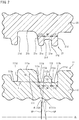
- FIG. 2 is a longitudinal cross-sectional view of the thread portions in the threaded connection 1 (cross-sectional view taken on a plane containing the pipe axis CL). For ease of explanation, FIG. 2 separately shows the male thread portion 11 and the female thread portion 21.
- the male thread portion 11 includes a main male thread 111 and an auxiliary male thread 112.
- the main male thread 111 is constituted by a trapezoidal thread that has a thread crest width and thread root width that are constant over the entire male thread portion 11.
- the main male thread 111 includes a plurality of thread crest surfaces 111a, a plurality of thread root surfaces 111b, a plurality of stabbing flanks 111c, and a plurality of loading flanks 111d.
- Each stabbing flank 111c is located toward the tip of the pin 10.
- the loading flank 111d is located on the side of the thread that is opposite to the stabbing flank 111c.
- each stabbing flank 111c and each loading flank 111d of the main male thread 111 are inclined toward the same direction. More specifically, the flank angle of each stabbing flank 111c is larger than 0 degrees, i.e. is a positive angle. The flank angle of each loading flank 111d is slightly smaller than 0 degrees, i.e. is a negative angle.
- Flank angle as used herein means the angle formed by a plane VP perpendicular to the pipe axis CL and the stabbing flank 111c or loading flank 111d. In FIG. 2 , the flank angle of each stabbing flank 111c is determined to be positive if it is a positive counterclockwise angle, while the flank angle of each loading flank 111d is determined to be positive if it is a positive clockwise angle.
- the auxiliary male thread 112 is provided on the thread root of the main male thread 111. That is, in a longitudinal cross section, each thread tooth of the auxiliary male thread 112 is provided between thread teeth of the main male thread 111.
- the auxiliary male thread 112 has a thread crest width and thread crest height that are smaller than the thread crest width and thread crest height of the main male thread 111.
- the longitudinal cross-sectional area of a thread tooth of the auxiliary male thread 112 is not larger than 50 % of the longitudinal cross-sectional area of a thread tooth of the main male thread 111.
- the auxiliary male thread 112 includes a plurality of thread crest surfaces 112a, a plurality of stabbing flanks 112c, and a plurality of loading flanks 112d.
- Each stabbing flank 112c is located toward the tip of the pin 10.
- the loading flank 112d is located on the side of the thread that is opposite to the stabbing flank 112c.
- Each stabbing flank 112c of the auxiliary male thread 112 faces the associated loading flank 111d of the main male thread 111.
- Each loading flank 112d of the auxiliary male thread 112 faces the associated stabbing flank 111c of the main male thread 111.
- Each stabbing flank 112c and each loading flank 112d of the auxiliary male thread 112 are inclined toward opposite directions. That is, the flank angles of each stabbing flank 112c and each loading flank 112d are larger than 0 degrees, i.e. are positive angles.
- Flank angle as used herein is the angle formed by a plane perpendicular to the pipe axis CL and the stabbing flank 112c or loading flank 112d. In FIG. 2 , the flank angle of each stabbing flank 112c is determined to be positive if it is a positive counterclockwise angle, while the flank angle of each loading flank 112d is determined to be positive if it is a positive clockwise angle.
- flank angle ⁇ 111c of the stabbing flank 111c of the main male thread 111 and the flank angle ⁇ 112d of the loading flank 112d of the auxiliary male thread 112 are larger than 0 degrees, i.e. are positive angles.
- the flank angle of the loading flank 111d of the main male thread 111 is smaller than 0 degrees, i.e. is a negative angle.
- the flank angle of the stabbing flank 112c of the auxiliary male thread 112 is larger than 0 degrees i.e. is a positive angle.
- the absolute value of the flank angle of the loading flank 111d is smaller than the absolute value of the flank angle of the stabbing flank 112c.
- the female thread portion 21 includes a plurality of thread crest surfaces 21a, a plurality of thread root surfaces 21b, a plurality of stabbing flanks 21c, and a plurality of loading flanks 21d.
- An auxiliary thread root 21e is formed in a thread crest of the female thread portion 21.
- a thread crest surface 21a, thread root surface 21b, stabbing flank 21c and loading flank 21d of the female thread portion 21 face a thread root surface 111b, thread crest surface 111a, stabbing flank 111c and loading flank 111d, respectively, of the main male thread 111.
- An auxiliary thread root 21e of the female thread portion 21 receives a thread crest of the auxiliary male thread 112.
- a thread crest surface 21a and loading flank 21d of the female thread portion 21 are in contact with a thread root surface 111b and loading flank 111d, respectively, of the main male thread 111.
- Thread crest surfaces 112a, stabbing flanks 112c and loading flanks 112d of the auxiliary male thread 112 are in contact with the bottom surface and a side wall of the auxiliary thread root 21e of the female thread portion 21.
- the width W2 of the auxiliary thread root 21e on the thread crest of the female thread portion 21 is slightly smaller than the width W1 of the auxiliary male thread 112.
- the length L21 in the pipe-axis direction between the stabbing flank 21c and the associated side wall of the auxiliary thread root 21e is slightly larger than the length L11 in the pipe-axis direction between the stabbing flank 111c of the main male thread and the loading flank 112d of the auxiliary male thread 112.
- the length L22 in the pipe-axis direction between the loading flank 21d and the associated side wall of the auxiliary thread root 21e is slightly larger than the length L12 in the pipe-axis direction between the loading flank 111d of the main male thread and the stabbing flank 112c of the auxiliary male thread 112.
- This construction will allow the auxiliary male thread 112 to be engaged with an interference fit to the female thread portion 21, thus increasing the strength of engagement between the thread portions, i.e. male thread portion 11 and female thread portion 21.
- an auxiliary male thread 112 is provided on the thread root of the main male thread 111, the auxiliary male thread having a thread crest width and thread crest height smaller than those of the main male thread 111.
- the thread crest of the auxiliary male thread 112 is received by the auxiliary thread root 21e of the female thread portion 21. This will make the area of engagement between the male and female threads 11 and 21 larger than that with conventional buttress threads, thereby providing higher torque resistance.
- the thread crest width and thread root width of the main male thread 111 of the male thread portion 11 and the thread crest width and thread root width of the female thread portion 21 corresponding to the male thread portion 11 are constant along the entire thread portion. This will allow the threads to be machined in a shorter time than wedge threads. This will reduce manufacturing costs.
- the width W2 of the auxiliary thread root 21e of the female thread portion 21 receiving the auxiliary male thread 112 is slightly smaller than the width W1 of the thread crest of the auxiliary male thread 112.
- the length L21 in the pipe-axis direction between the stabbing flank 21c and the loading flank 21f of the auxiliary thread root 21e is slightly larger than the length L11 in the pipe-axis direction between the stabbing flank 111c of the main male thread and the loading flank 112d of the auxiliary male thread 112.
- the length L22 in the pipe-axis direction between the loading flank 21d and the stabbing flank 21g of the auxiliary thread root 21e is slightly larger than the length L12 in the pipe-axis direction between the loading flank 111d of the main male thread and the stabbing flank 112c of the auxiliary male thread 112. This will allow the auxiliary male thread 112 and the female thread portion 21 to be engaged with an interference fit, thus increasing the strength of engagement between the thread portions. This will further improve torque resistance.
- the auxiliary male thread 112 is provided in the male thread portion 11 such that the area of engagement and the strength of engagement between the thread portions are increased.
- the external pressure is prevented from penetrating between the thread portions and through the seal. This will improve sealing performance against an external pressure.
- a model of the threaded connection 1 having an auxiliary male thread 112 on the thread root of the main male thread 111 was created ( FIG. 1 ).
- a model of a threaded connection 2 with buttress threads was created ( FIG. 3 ).
- the threaded connection 2 of the comparative example had the same construction as the threaded connection 1 of the inventive example except for the absence of the auxiliary male thread 112.
- the size of the steel pipes was 5" 18# (pipe-body outer diameter: 127.00 mm; pipe-body inner diameter: 108.61 mm), and the material was API carbon steel, P110 (nominal yield stress (YS): 758 MPa).
- the torque resistance of each of the created models was evaluated by causing the shoulders 13 and 23 of the pin 10 and box 20 to contact each other and then increasing tightening turns, determining the point at which the slope of the line representing tightening torque changes and, with yield torque defined as the torque at that point, using the value of yield torque to evaluate torque resistance. Further, the sealing performance of each of the created models was evaluated by determining the minimum seal contact force obtained under load conditions simulating the ISO 13679, series A test (minimum seal contact force).
- FIGS. 4 and 5 show the obtained yield torques and minimum seal contact forces.
- the yield torque and minimum seal contact force of the threaded connection 1 of the inventive example ( FIG. 1 ) are significantly larger than those of the threaded connection 2 of the comparative example ( FIG. 3 ). This demonstrates that providing the auxiliary male thread 112 on the thread root of the main male thread 111 significantly improves torque resistance and sealing performance.
- an excessively large longitudinal cross-sectional area S1 of a thread tooth of the auxiliary thread 112 may cause problems when producing and making up the thread portions; accordingly, the longitudinal cross-sectional area S1 of a thread tooth of the auxiliary male thread 112 is not larger than 40 % of the longitudinal cross-sectional area S2 of a thread tooth of the main male thread 111.
- the longitudinal cross-sectional area S1 of a thread tooth of the auxiliary male thread 112 is the area enclosed by the outer profile of a thread tooth of the auxiliary male thread 112 and a line L connecting the thread roots 111b in a longitudinal cross section of a thread tooth of the auxiliary male thread 112. Further, as shown in FIG.
- the longitudinal cross-sectional area S2 of a thread tooth of the main male thread 111 is the area enclosed by the outer profile of a thread tooth of the main male thread 111 and a line L connecting the thread roots 111b in a longitudinal cross section of a thread tooth of the main male thread 111.
Landscapes
- Engineering & Computer Science (AREA)
- General Engineering & Computer Science (AREA)
- Mechanical Engineering (AREA)
- Mining & Mineral Resources (AREA)
- Life Sciences & Earth Sciences (AREA)
- Structural Engineering (AREA)
- General Life Sciences & Earth Sciences (AREA)
- Geology (AREA)
- Physics & Mathematics (AREA)
- Fluid Mechanics (AREA)
- Geochemistry & Mineralogy (AREA)
- Environmental & Geological Engineering (AREA)
- Paleontology (AREA)
- Civil Engineering (AREA)
- Non-Disconnectible Joints And Screw-Threaded Joints (AREA)
Abstract
Description
- The present disclosure relates to a threaded connection used to connect steel pipes.
- In oil wells or natural-gas wells (hereinafter collectively referred to as "oil wells" or the like), oil country tubular goods (OCTGs) such as casing and tubing are used for prospecting underground resources. An OCTG is composed of a series of steel pipes connected together by means of a threaded connection.
- Such threaded connections for steel pipe are generally categorized as coupling type and integral type. A coupling-type connection connects a pair of pipes, one of which is a steel pipe and the other one is a short pipe called coupling. In this case, a male thread is provided on the outer periphery of each of the ends of the steel pipe, while a female thread is provided on the inner periphery of each of the ends of the coupling. Then, a male thread of the steel pipe is screwed into a female thread of the coupling such that the steel pipe and coupling are made up and connected. An integral-type connection connects a pair of pipes that are both steel pipes, and does not use a separate coupling. In this case, a male thread is provided on the outer periphery of one end of each steel pipe, while a female thread is provided on the inner periphery of the other end. Then, the male thread of the one steel pipe is screwed into the female thread of the other steel pipe such that these pipes are made up and connected.
- A connection portion of a pipe end on which a male thread is provided includes an element to be inserted into a female thread, and thus is usually referred to as pin. A connection portion of a pipe end on which a female thread is provided includes an element for receiving a male thread, and thus is referred to as box. A pin and a box constitute ends of pipes and are thus tubular in shape.
- In recent years, development of new techniques, such as horizontal drilling and directional drilling, has created demand for threaded connections with high torque resistance and high sealing performance. To provide both torque resistance and sealing performance, it is effective if the screw threads used are dovetail-shaped tapered threads, for example, which may referred to as wedge threads. In a threaded connection having wedge threads, the thread crest width of the male thread (on the pin) decreases in the direction in which a right-handed thread advances along the helix of the thread such that the thread is tapered, while the thread root width of the opposite female thread (on the box) decreases in the direction in which a right-handed thread advances along the helix of the thread such that the thread is tapered. In a wedge thread, both the loading flank and stabbing flank have negative angles, and loading flanks contact each other while stabbing flanks contact each other. Thus, the entire threads strongly engage, exhibiting high torque performance. Further, when the connection has been made up, the thread crests and thread roots of the threads are in contact with each other, thereby providing a certain sealing performance.
- On the other hand,
Patent Documents - In the threaded connection of
Patent Document 1, a cross section of each of the loading and stabbing flanks of each thread is Z-shaped. With this threaded connection, loading flanks and stabbing flanks with such a shape are brought into contact to control the axial and radial tightening of the threads. - In the threaded connection of
Patent Document 2, a cross section of each of the loading flanks of the threads is hook-shaped. Thus, when the connection has been made up, the hook-shaped loading flanks engage each other. Thus, the threads may be burdened with some of the torsional torque with which the torque shoulders are burdened, reducing plastic deformation of the torque shoulders and exhibiting high torque resistance. - The following prior art documents are incorporated herein by reference.
- Patent Document 1:
U.S. Patent Application Publication No. 2008/0073909 A - Patent Document 2:
JP 2002-81584 A - In a threaded connection in which the threads used are wedge threads, the thread crest width of the male thread and the thread root width of the corresponding female thread change. This makes it difficult to machine the threads and prolongs machining time, resulting in high manufacturing costs. To reduce manufacturing costs, the threads used may be buttress threads (or trapezoidal threads) in accordance with the American Petroleum Institute (API) standards. However, a threaded connection using buttress threads does not exhibit high torque resistance unless a torque amplification mechanism, such as torque shoulders, is provided.
- An object of the present disclosure is to provide a threaded connection for steel pipe that can both provide a certain torque resistance and reduce manufacturing costs.
- A threaded connection for steel pipe according to the present disclosure includes a tubular pin and a tubular box. The pin includes a male thread portion on an outer periphery. The box includes, on an inner periphery, a female thread portion corresponding to the male thread portion and adapted to be made up on the pin. The male thread portion includes a main male thread and an auxiliary male thread. The main male thread is constituted by a trapezoidal thread having a constant thread crest width and a constant thread root width. The auxiliary male thread is located on a thread root of the main male thread and has a thread crest width and a thread crest height that are smaller than the thread crest width and the thread crest height of the main male thread. Each of the main male thread and the auxiliary male thread has a stabbing flank and a loading flank located opposite to the stabbing flank. In a cross section containing a pipe axis of the pin, a flank angle of the stabbing flank of the main male thread and a flank angle of the loading flank of the auxiliary male thread at adjacent locations are larger than 0 degrees.
- The threaded connection for steel pipe according to the present disclosure reduces manufacturing costs while providing a certain torque resistance.
-
- [
FIG. 1] FIG. 1 is a longitudinal cross-sectional view of a threaded connection for steel pipe according to an embodiment. - [
FIG. 2] FIG. 2 is a longitudinal cross-sectional view of the thread portions in the threaded connection for steel pipe shown inFIG. 1 . - [
FIG. 3] FIG. 3 is a longitudinal cross-sectional view of a threaded connection for steel pipe according to a conventional technique (comparative example). - [
FIG. 4] FIG. 4 is a graph showing yield torque in the threaded connections for steel pipe according to an inventive example and a comparative example. - [
FIG. 5] FIG. 5 is a graph showing minimum seal contact force in the threaded connections for steel pipe according to the inventive and comparative examples. - The inventors of the threaded connection for steel pipe according to the embodiment attempted to let mainly the thread portions exhibit torque resistance starting from buttress threads (trapezoidal threads) in accordance with the API standards and varying thread shape.
- A threaded connection for steel pipe according to an embodiment includes a tubular pin and a tubular box. The pin includes a male thread portion on an outer periphery. The box includes, on an inner periphery, a female thread portion corresponding to the male thread portion and adapted to be made up on the pin. The male thread portion includes a main male thread and an auxiliary male thread. The main male thread is constituted by a trapezoidal thread having a constant thread crest width and a constant thread root width. The auxiliary male thread is located on a thread root of the main male thread and has a thread crest width and a thread crest height that are smaller than the thread crest width and the thread crest height of the main male thread. Each of the main male thread and the auxiliary male thread has a stabbing flank and a loading flank located opposite to the stabbing flank. In a cross section containing a pipe axis of the pin, a flank angle of the stabbing flank of the main male thread and a flank angle of the loading flank of the male thread at adjacent locations are larger than 0 degrees.
- In the male thread portion in the above-described threaded connection, an auxiliary male thread having a thread crest width and a thread crest height smaller than the main male thread is provided on the thread root of the main male thread. The female thread portion is constructed to correspond to the male thread portion. This construction will make the area of engagement between the male and female thread portions larger than that with conventional buttress threads. This will provide higher torque resistance.
- Further, in the male thread portion in the above-described threaded connection, the main male thread is constituted by a trapezoidal thread with a constant thread crest width and a constant thread root width. This will allow the thread to be machined in a shorter time than a wedge thread. This will reduce manufacturing costs.
- An embodiment will be described below with reference to the drawings. The same and corresponding components in the drawings will be labeled with the same characters and the same description will not be repeated.
-
FIG. 1 is a longitudinal cross-sectional view of a threadedconnection 1 for steel pipe according to the present embodiment (cross-sectional view taken on a plane containing the pipe axis CL). The threadedconnection 1 may be an integral-type threaded connection, or may be a coupling-type threaded connection. The threadedconnection 1 includes apin 10 and abox 20. - The
pin 10 includes amale thread portion 11, a sealingsurface 12, and ashoulder surface 13. Themale thread portion 11 includes a mainmale thread 111 and an auxiliarymale thread 112. Themale thread portion 11 and sealingsurface 12 are provided on the outer periphery of thepin 10. The sealingsurface 12 is located closer to the tip of thepin 10 than themale thread portion 11 is. Theshoulder surface 13 is provided on the tip of thepin 10. - The
box 20 includes afemale thread portion 21, a sealingsurface 22, and ashoulder surface 23. Thefemale thread portion 21, sealingsurface 22 andshoulder surface 23 are provided to correspond to themale thread portion 11, sealingsurface 12 andshoulder surface 13 of thepin 10. - The
male thread portion 11 andfemale thread portion 21 are fitted into each other when the connection has been made up to form an interference fit. - The sealing surfaces 12 and 22 come into contact with each other as the
pin 10 is screwed into thebox 20, are fitted into each other when the connection has been made up to form an interference fit. Thus, the sealing surfaces 12 and 22 form a seal by a metal-to-metal contact. - As the
pin 10 is screwed into thebox 20, the shoulder surfaces 13 and 23 come into contact with each other and are pressed against each other. The shoulder surfaces 13 and 23 limit screw-in of thepin 10 into thebox 20, and gives the male thread portion 11 a load in a direction opposite to the direction of advancement of screw-in, i.e. a thread-tightening axial force. -
FIG. 2 is a longitudinal cross-sectional view of the thread portions in the threaded connection 1 (cross-sectional view taken on a plane containing the pipe axis CL). For ease of explanation,FIG. 2 separately shows themale thread portion 11 and thefemale thread portion 21. - As discussed above, the
male thread portion 11 includes a mainmale thread 111 and an auxiliarymale thread 112. The mainmale thread 111 is constituted by a trapezoidal thread that has a thread crest width and thread root width that are constant over the entiremale thread portion 11. In a longitudinal cross section, the mainmale thread 111 includes a plurality ofthread crest surfaces 111a, a plurality of thread root surfaces 111b, a plurality of stabbingflanks 111c, and a plurality ofloading flanks 111d. Eachstabbing flank 111c is located toward the tip of thepin 10. For each thread tooth of the mainmale thread 111, theloading flank 111d is located on the side of the thread that is opposite to thestabbing flank 111c. - Each
stabbing flank 111c and eachloading flank 111d of the mainmale thread 111 are inclined toward the same direction. More specifically, the flank angle of eachstabbing flank 111c is larger than 0 degrees, i.e. is a positive angle. The flank angle of eachloading flank 111d is slightly smaller than 0 degrees, i.e. is a negative angle. Flank angle as used herein means the angle formed by a plane VP perpendicular to the pipe axis CL and thestabbing flank 111c or loadingflank 111d. InFIG. 2 , the flank angle of eachstabbing flank 111c is determined to be positive if it is a positive counterclockwise angle, while the flank angle of eachloading flank 111d is determined to be positive if it is a positive clockwise angle. - The auxiliary
male thread 112 is provided on the thread root of the mainmale thread 111. That is, in a longitudinal cross section, each thread tooth of the auxiliarymale thread 112 is provided between thread teeth of the mainmale thread 111. The auxiliarymale thread 112 has a thread crest width and thread crest height that are smaller than the thread crest width and thread crest height of the mainmale thread 111. For example, the longitudinal cross-sectional area of a thread tooth of the auxiliarymale thread 112 is not larger than 50 % of the longitudinal cross-sectional area of a thread tooth of the mainmale thread 111. - In a longitudinal cross section, the auxiliary
male thread 112 includes a plurality ofthread crest surfaces 112a, a plurality of stabbingflanks 112c, and a plurality ofloading flanks 112d. Eachstabbing flank 112c is located toward the tip of thepin 10. For each thread tooth of the auxiliarymale thread 112, theloading flank 112d is located on the side of the thread that is opposite to thestabbing flank 112c. Eachstabbing flank 112c of the auxiliarymale thread 112 faces the associatedloading flank 111d of the mainmale thread 111. Eachloading flank 112d of the auxiliarymale thread 112 faces the associatedstabbing flank 111c of the mainmale thread 111. - Each
stabbing flank 112c and eachloading flank 112d of the auxiliarymale thread 112 are inclined toward opposite directions. That is, the flank angles of eachstabbing flank 112c and eachloading flank 112d are larger than 0 degrees, i.e. are positive angles. Flank angle as used herein is the angle formed by a plane perpendicular to the pipe axis CL and thestabbing flank 112c or loadingflank 112d. InFIG. 2 , the flank angle of eachstabbing flank 112c is determined to be positive if it is a positive counterclockwise angle, while the flank angle of eachloading flank 112d is determined to be positive if it is a positive clockwise angle. - In a longitudinal cross section of the pin 10 (i.e. cross section containing the pipe axis), the flank angle θ111c of the
stabbing flank 111c of the mainmale thread 111 and the flank angle θ112d of theloading flank 112d of the auxiliarymale thread 112 are larger than 0 degrees, i.e. are positive angles. Although not shown, the flank angle of theloading flank 111d of the mainmale thread 111 is smaller than 0 degrees, i.e. is a negative angle. The flank angle of thestabbing flank 112c of the auxiliarymale thread 112 is larger than 0 degrees i.e. is a positive angle. Although not limiting, the absolute value of the flank angle of theloading flank 111d is smaller than the absolute value of the flank angle of thestabbing flank 112c. - In a longitudinal cross section, the
female thread portion 21 includes a plurality ofthread crest surfaces 21a, a plurality of thread root surfaces 21b, a plurality of stabbingflanks 21c, and a plurality ofloading flanks 21d. Anauxiliary thread root 21e is formed in a thread crest of thefemale thread portion 21. - A
thread crest surface 21a,thread root surface 21b, stabbingflank 21c andloading flank 21d of thefemale thread portion 21 face athread root surface 111b,thread crest surface 111a, stabbingflank 111c andloading flank 111d, respectively, of the mainmale thread 111. Anauxiliary thread root 21e of thefemale thread portion 21 receives a thread crest of the auxiliarymale thread 112. - When the connection has been made up, a
thread crest surface 21a andloading flank 21d of thefemale thread portion 21 are in contact with athread root surface 111b andloading flank 111d, respectively, of the mainmale thread 111.Thread crest surfaces 112a, stabbingflanks 112c andloading flanks 112d of the auxiliarymale thread 112 are in contact with the bottom surface and a side wall of theauxiliary thread root 21e of thefemale thread portion 21. - The width W2 of the
auxiliary thread root 21e on the thread crest of thefemale thread portion 21 is slightly smaller than the width W1 of the auxiliarymale thread 112. For a thread tooth of thefemale thread portion 21, the length L21 in the pipe-axis direction between the stabbingflank 21c and the associated side wall of theauxiliary thread root 21e is slightly larger than the length L11 in the pipe-axis direction between the stabbingflank 111c of the main male thread and theloading flank 112d of the auxiliarymale thread 112. Further, for a thread tooth of thefemale thread portion 21, the length L22 in the pipe-axis direction between theloading flank 21d and the associated side wall of theauxiliary thread root 21e is slightly larger than the length L12 in the pipe-axis direction between theloading flank 111d of the main male thread and thestabbing flank 112c of the auxiliarymale thread 112. This construction will allow the auxiliarymale thread 112 to be engaged with an interference fit to thefemale thread portion 21, thus increasing the strength of engagement between the thread portions, i.e.male thread portion 11 andfemale thread portion 21. - Thus, in the threaded
connection 1 according to the present embodiment, an auxiliarymale thread 112 is provided on the thread root of the mainmale thread 111, the auxiliary male thread having a thread crest width and thread crest height smaller than those of the mainmale thread 111. When the connection has been made up, the thread crest of the auxiliarymale thread 112 is received by theauxiliary thread root 21e of thefemale thread portion 21. This will make the area of engagement between the male andfemale threads - Further, according to the present embodiment, the thread crest width and thread root width of the main
male thread 111 of themale thread portion 11 and the thread crest width and thread root width of thefemale thread portion 21 corresponding to themale thread portion 11 are constant along the entire thread portion. This will allow the threads to be machined in a shorter time than wedge threads. This will reduce manufacturing costs. - According to the present embodiment, the width W2 of the
auxiliary thread root 21e of thefemale thread portion 21 receiving the auxiliarymale thread 112 is slightly smaller than the width W1 of the thread crest of the auxiliarymale thread 112. In a thread tooth of thefemale thread portion 21, the length L21 in the pipe-axis direction between the stabbingflank 21c and theloading flank 21f of theauxiliary thread root 21e (i.e. side opposite to thestabbing flank 21c) is slightly larger than the length L11 in the pipe-axis direction between the stabbingflank 111c of the main male thread and theloading flank 112d of the auxiliarymale thread 112. Further, in a thread tooth of thefemale thread portion 21, the length L22 in the pipe-axis direction between theloading flank 21d and thestabbing flank 21g of theauxiliary thread root 21e (side opposite to theloading flank 21d) is slightly larger than the length L12 in the pipe-axis direction between theloading flank 111d of the main male thread and thestabbing flank 112c of the auxiliarymale thread 112. This will allow the auxiliarymale thread 112 and thefemale thread portion 21 to be engaged with an interference fit, thus increasing the strength of engagement between the thread portions. This will further improve torque resistance. - As discussed above, according to the present embodiment, the auxiliary
male thread 112 is provided in themale thread portion 11 such that the area of engagement and the strength of engagement between the thread portions are increased. Thus, even when an external pressure is applied to the thread portions, the external pressure is prevented from penetrating between the thread portions and through the seal. This will improve sealing performance against an external pressure. - To verify the effects of the threaded connection for steel pipe according to the present disclosure, numerical simulation analyses by the elasto-plastic finite element method were conducted.
- To provide an inventive example, a model of the threaded
connection 1 having an auxiliarymale thread 112 on the thread root of the mainmale thread 111 was created (FIG. 1 ). To illustrate a conventional technique for comparison (comparative example), a model of a threadedconnection 2 with buttress threads was created (FIG. 3 ). The threadedconnection 2 of the comparative example had the same construction as the threadedconnection 1 of the inventive example except for the absence of the auxiliarymale thread 112. The size of the steel pipes was 5" 18# (pipe-body outer diameter: 127.00 mm; pipe-body inner diameter: 108.61 mm), and the material was API carbon steel, P110 (nominal yield stress (YS): 758 MPa). - During analysis, the torque resistance of each of the created models was evaluated by causing the
shoulders pin 10 andbox 20 to contact each other and then increasing tightening turns, determining the point at which the slope of the line representing tightening torque changes and, with yield torque defined as the torque at that point, using the value of yield torque to evaluate torque resistance. Further, the sealing performance of each of the created models was evaluated by determining the minimum seal contact force obtained under load conditions simulating the ISO 13679, series A test (minimum seal contact force). -
FIGS. 4 and 5 show the obtained yield torques and minimum seal contact forces. As shown inFIGS. 4 and 5 , the yield torque and minimum seal contact force of the threadedconnection 1 of the inventive example (FIG. 1 ) are significantly larger than those of the threadedconnection 2 of the comparative example (FIG. 3 ). This demonstrates that providing the auxiliarymale thread 112 on the thread root of the mainmale thread 111 significantly improves torque resistance and sealing performance. - It is preferable to provide a certain amount of longitudinal cross-sectional area of a thread tooth of the auxiliary
male thread 112. This is because that will increase the contact area between the thread portions when the connection has been made up and, at the same time, significantly improve torque resistance over conventional techniques. This also applies to external-pressure sealing performance, discussed above. The present embodiment suggests that, to improve external-pressure sealing performance, it is desirable that the longitudinal cross-sectional area S1 of a thread tooth of the auxiliarymale thread 112 be equal to or larger than 15 % of the longitudinal cross-sectional area S2 of a thread tooth of the mainmale thread 111. However, an excessively large longitudinal cross-sectional area S1 of a thread tooth of theauxiliary thread 112 may cause problems when producing and making up the thread portions; accordingly, the longitudinal cross-sectional area S1 of a thread tooth of the auxiliarymale thread 112 is not larger than 40 % of the longitudinal cross-sectional area S2 of a thread tooth of the mainmale thread 111. As shown inFIG. 2 , the longitudinal cross-sectional area S1 of a thread tooth of the auxiliarymale thread 112 is the area enclosed by the outer profile of a thread tooth of the auxiliarymale thread 112 and a line L connecting thethread roots 111b in a longitudinal cross section of a thread tooth of the auxiliarymale thread 112. Further, as shown inFIG. 2 , the longitudinal cross-sectional area S2 of a thread tooth of the mainmale thread 111 is the area enclosed by the outer profile of a thread tooth of the mainmale thread 111 and a line L connecting thethread roots 111b in a longitudinal cross section of a thread tooth of the mainmale thread 111. -
- 1: threaded connection for steel pipe
- 10: pin
- 11: male thread portion
- 111: main male thread
- 111c: stabbing flank
- 111d: loading flank
- 112: auxiliary male thread
- 112c: stabbing flank
- 112d: loading flank
- 20: box
- 21: female thread portion
Claims (2)
- A threaded connection for steel pipe comprising:a tubular pin including a male thread portion on an outer periphery; anda tubular box including, on an inner periphery, a female thread portion corresponding to the male thread portion and adapted to be made up on the pin,wherein the male thread portion includes a main male thread constituted by a trapezoidal thread having a constant thread crest width and a constant thread root width, and an auxiliary male thread located on a thread root of the main male thread and having a thread crest width and a thread crest height that are smaller than the thread crest width and the thread crest height of the main male thread,each of the main male thread and the auxiliary male thread has a stabbing flank and a loading flank located opposite to the stabbing flank, and,in a cross section containing a pipe axis of the pin, a flank angle of the stabbing flank of the main male thread and a flank angle of the loading flank of the auxiliary male thread at adjacent locations are larger than 0 degrees.
- The threaded connection for steel pipe according to claim 1, wherein a thread tooth of the auxiliary male thread has a longitudinal cross-sectional area of 15 to 40 % of a longitudinal cross-sectional area of a thread tooth of the main male thread adjacent to the auxiliary male thread.
Applications Claiming Priority (2)
| Application Number | Priority Date | Filing Date | Title |
|---|---|---|---|
| JP2017103956 | 2017-05-25 | ||
| PCT/JP2018/014903 WO2018216375A1 (en) | 2017-05-25 | 2018-04-09 | Threaded joint for steel pipes |
Publications (2)
| Publication Number | Publication Date |
|---|---|
| EP3633254A1 true EP3633254A1 (en) | 2020-04-08 |
| EP3633254A4 EP3633254A4 (en) | 2020-06-17 |
Family
ID=64396580
Family Applications (1)
| Application Number | Title | Priority Date | Filing Date |
|---|---|---|---|
| EP18805430.8A Withdrawn EP3633254A4 (en) | 2017-05-25 | 2018-04-09 | Threaded joint for steel pipes |
Country Status (9)
| Country | Link |
|---|---|
| US (1) | US20200141522A1 (en) |
| EP (1) | EP3633254A4 (en) |
| JP (1) | JP6703191B2 (en) |
| CN (1) | CN110678685A (en) |
| BR (1) | BR112019020903A2 (en) |
| CA (1) | CA3064654A1 (en) |
| MX (1) | MX2019013680A (en) |
| RU (1) | RU2721075C1 (en) |
| WO (1) | WO2018216375A1 (en) |
Family Cites Families (12)
| Publication number | Priority date | Publication date | Assignee | Title |
|---|---|---|---|---|
| KR900002192B1 (en) * | 1985-11-22 | 1990-04-04 | 닛봉도꾸슈우기자이가부시끼가이샤 | Screw with groove for self-lock and method and rolling flat die for manufacturing the same |
| JP3756652B2 (en) * | 1998-01-08 | 2006-03-15 | 新日本製鐵株式会社 | Pipe fitting |
| UA66876C2 (en) * | 1998-09-07 | 2004-06-15 | Валлурек Маннесманн Ойл Енд Гес Франс | Threaded joint of two metal pipes with a slot made in the threading |
| JP3714138B2 (en) | 2000-09-08 | 2005-11-09 | 住友金属工業株式会社 | Pipe threaded joints |
| FR2820806B1 (en) * | 2001-02-09 | 2004-02-20 | Vallourec Mannesmann Oil & Gas | TUBULAR THREAD JOINT WITH CONVEXED BOMBED THREAD SIDE |
| US6767035B2 (en) * | 2002-03-11 | 2004-07-27 | Weatherford/Lamb, Inc. | High torque modified profile threaded tubular connection |
| FR2863681B1 (en) * | 2003-12-11 | 2006-02-24 | Vallourec Mannesmann Oil & Gas | FATIGUE-RESISTANT THREADED TUBULAR JOINT |
| TWM284777U (en) * | 2005-08-09 | 2006-01-01 | Tqc Fasteners Ind Corp | Improved structure of anti-disengaging screw |
| US7588269B2 (en) | 2006-09-26 | 2009-09-15 | Gandy Technologies Corporation | Z-shaped thread form for tubular connections |
| JP5923911B2 (en) * | 2011-03-22 | 2016-05-25 | Jfeスチール株式会社 | Threaded joints for steel pipes |
| CN203548520U (en) * | 2013-11-20 | 2014-04-16 | 浙江群展精密紧固件有限公司 | Fast-tapping and loosening-prevention stud |
| FR3014534B1 (en) * | 2013-12-10 | 2015-12-04 | Vallourec Oil & Gas France | ASSEMBLY FOR THE PRODUCTION OF A THREADED JOINT FOR DRILLING AND OPERATING HYDROCARBON WELLS AND RESULTING THREAD |
-
2018
- 2018-04-09 EP EP18805430.8A patent/EP3633254A4/en not_active Withdrawn
- 2018-04-09 CN CN201880033995.8A patent/CN110678685A/en not_active Withdrawn
- 2018-04-09 RU RU2019137441A patent/RU2721075C1/en not_active IP Right Cessation
- 2018-04-09 CA CA3064654A patent/CA3064654A1/en not_active Abandoned
- 2018-04-09 BR BR112019020903A patent/BR112019020903A2/en not_active IP Right Cessation
- 2018-04-09 WO PCT/JP2018/014903 patent/WO2018216375A1/en active Application Filing
- 2018-04-09 US US16/613,876 patent/US20200141522A1/en not_active Abandoned
- 2018-04-09 JP JP2019519507A patent/JP6703191B2/en not_active Expired - Fee Related
- 2018-04-09 MX MX2019013680A patent/MX2019013680A/en unknown
Also Published As
| Publication number | Publication date |
|---|---|
| CA3064654A1 (en) | 2018-11-29 |
| WO2018216375A1 (en) | 2018-11-29 |
| CN110678685A (en) | 2020-01-10 |
| JPWO2018216375A1 (en) | 2019-11-21 |
| JP6703191B2 (en) | 2020-06-03 |
| EP3633254A4 (en) | 2020-06-17 |
| BR112019020903A2 (en) | 2020-04-28 |
| US20200141522A1 (en) | 2020-05-07 |
| RU2721075C1 (en) | 2020-05-15 |
| MX2019013680A (en) | 2020-01-15 |
Similar Documents
| Publication | Publication Date | Title |
|---|---|---|
| US6848724B2 (en) | Thread design for uniform distribution of makeup forces | |
| JP7186221B2 (en) | Threaded connection with partial self-locking engagement | |
| US11300233B2 (en) | Threaded connection for steel pipe | |
| CA3006937C (en) | Threaded joint for steel pipe | |
| US20210231240A1 (en) | Threaded Connection | |
| EP3409991B1 (en) | Threaded joint for steel pipe | |
| AU2020327779B2 (en) | Threaded connection for steel pipe | |
| WO2018211873A1 (en) | Threaded coupling for steel piping | |
| US20200102797A1 (en) | Threaded connection for tubular component | |
| CA3145225C (en) | Threaded connection | |
| US20190195030A1 (en) | Wedge threadform having crest to root thread compound relief areas | |
| EP4174354A1 (en) | Threaded joint for steel pipe | |
| EP3633254A1 (en) | Threaded joint for steel pipes | |
| CA3109443C (en) | Threaded connection for steel pipes | |
| US20230313620A1 (en) | Threaded connection for pipe | |
| OA21386A (en) | Threaded joint for steel pipe. | |
| OA20943A (en) | Threaded coupling for steel pipe |
Legal Events
| Date | Code | Title | Description |
|---|---|---|---|
| STAA | Information on the status of an ep patent application or granted ep patent |
Free format text: STATUS: THE INTERNATIONAL PUBLICATION HAS BEEN MADE |
|
| PUAI | Public reference made under article 153(3) epc to a published international application that has entered the european phase |
Free format text: ORIGINAL CODE: 0009012 |
|
| STAA | Information on the status of an ep patent application or granted ep patent |
Free format text: STATUS: REQUEST FOR EXAMINATION WAS MADE |
|
| 17P | Request for examination filed |
Effective date: 20191011 |
|
| AK | Designated contracting states |
Kind code of ref document: A1 Designated state(s): AL AT BE BG CH CY CZ DE DK EE ES FI FR GB GR HR HU IE IS IT LI LT LU LV MC MK MT NL NO PL PT RO RS SE SI SK SM TR |
|
| AX | Request for extension of the european patent |
Extension state: BA ME |
|
| A4 | Supplementary search report drawn up and despatched |
Effective date: 20200518 |
|
| RIC1 | Information provided on ipc code assigned before grant |
Ipc: F16L 15/00 20060101ALI20200512BHEP Ipc: E21B 17/042 20060101ALI20200512BHEP Ipc: E02D 5/24 20060101ALI20200512BHEP Ipc: F16L 15/06 20060101ALI20200512BHEP Ipc: F16L 15/04 20060101AFI20200512BHEP |
|
| DAV | Request for validation of the european patent (deleted) | ||
| DAX | Request for extension of the european patent (deleted) | ||
| STAA | Information on the status of an ep patent application or granted ep patent |
Free format text: STATUS: THE APPLICATION IS DEEMED TO BE WITHDRAWN |
|
| 18D | Application deemed to be withdrawn |
Effective date: 20201216 |