EP3633234A1 - Linear actuator - Google Patents
Linear actuator Download PDFInfo
- Publication number
- EP3633234A1 EP3633234A1 EP19200936.3A EP19200936A EP3633234A1 EP 3633234 A1 EP3633234 A1 EP 3633234A1 EP 19200936 A EP19200936 A EP 19200936A EP 3633234 A1 EP3633234 A1 EP 3633234A1
- Authority
- EP
- European Patent Office
- Prior art keywords
- ball screw
- friction springs
- tie rod
- springs
- actuator according
- Prior art date
- Legal status (The legal status is an assumption and is not a legal conclusion. Google has not performed a legal analysis and makes no representation as to the accuracy of the status listed.)
- Granted
Links
- 238000000034 method Methods 0.000 claims description 9
- 125000006850 spacer group Chemical group 0.000 claims description 8
- 239000000463 material Substances 0.000 description 2
- 238000012986 modification Methods 0.000 description 2
- 230000004048 modification Effects 0.000 description 2
- 230000000007 visual effect Effects 0.000 description 2
- 230000006835 compression Effects 0.000 description 1
- 238000007906 compression Methods 0.000 description 1
- 238000010276 construction Methods 0.000 description 1
- 238000004519 manufacturing process Methods 0.000 description 1
- 230000008569 process Effects 0.000 description 1
- 239000003381 stabilizer Substances 0.000 description 1
- 230000007704 transition Effects 0.000 description 1
Images

Classifications
-
- F—MECHANICAL ENGINEERING; LIGHTING; HEATING; WEAPONS; BLASTING
- F16—ENGINEERING ELEMENTS AND UNITS; GENERAL MEASURES FOR PRODUCING AND MAINTAINING EFFECTIVE FUNCTIONING OF MACHINES OR INSTALLATIONS; THERMAL INSULATION IN GENERAL
- F16H—GEARING
- F16H25/00—Gearings comprising primarily only cams, cam-followers and screw-and-nut mechanisms
- F16H25/18—Gearings comprising primarily only cams, cam-followers and screw-and-nut mechanisms for conveying or interconverting oscillating or reciprocating motions
- F16H25/20—Screw mechanisms
- F16H25/205—Screw mechanisms comprising alternate power paths, e.g. for fail safe back-up
-
- F—MECHANICAL ENGINEERING; LIGHTING; HEATING; WEAPONS; BLASTING
- F16—ENGINEERING ELEMENTS AND UNITS; GENERAL MEASURES FOR PRODUCING AND MAINTAINING EFFECTIVE FUNCTIONING OF MACHINES OR INSTALLATIONS; THERMAL INSULATION IN GENERAL
- F16H—GEARING
- F16H25/00—Gearings comprising primarily only cams, cam-followers and screw-and-nut mechanisms
- F16H25/18—Gearings comprising primarily only cams, cam-followers and screw-and-nut mechanisms for conveying or interconverting oscillating or reciprocating motions
- F16H25/20—Screw mechanisms
- F16H25/22—Screw mechanisms with balls, rollers, or similar members between the co-operating parts; Elements essential to the use of such members
- F16H25/2204—Screw mechanisms with balls, rollers, or similar members between the co-operating parts; Elements essential to the use of such members with balls
Definitions
- the present disclosure generally relates to linear actuators, including linear actuators that may be used in connection aircraft, such as with aircraft flaps, trim components, and/or stabilizers.
- Some actuators do not provide any indication that primary or backup components have failed, and/or it may be difficult to determine if primary or backup components have failed.
- an actuator may include a housing, a ball screw engaged with the housing, a tie rod disposed in the ball screw, a plurality of friction springs in the ball screw and around the tie rod, and/or a bearing that may be interference fit with the tie rod and clearance fit with the ball screw.
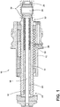
- an actuator 10 may include a housing 12, a ball screw 14, a tie rod 16, an adjusting nut 18, inner friction springs 20, outer friction springs 22, a spacer 24, and/or a bearing 26.
- the actuator 10 may be connected to an external component 28, such as an aircraft structure.
- the ball screw 14 may be disposed at least partially in the housing 12.
- the ball screw 14 may be engaged with the housing 12 such that rotation of one of the ball screw 14 and the housing 12 (or one or more components thereof) may cause translation of the other of the ball screw 14 and the housing 12.
- the ball screw 12 may include a first end 30 and a second end 30.
- the bearing 26 may be disposed at or about the second end 32 of the ball screw 14.
- the friction springs 20, 22 may be disposed in the ball screw 14 and/or disposed around the tie rod 16.
- the friction springs 20, 22 may include one or more of a variety of shapes, sizes, configurations, and/or materials.
- the friction springs 20, 22 may include C-shaped configurations.
- the outer friction springs 22 may include larger outer diameters than the inner friction springs 20.
- the outer friction springs 22 and the inner friction springs 20 may be disposed in an alternating configuration along the tie rod 16.
- a spacer 24 may be disposed in the ball screw 14 and may extend from the adjusting nut 18 to the friction springs 20, 22.
- the spacer 24 may be configured to facilitate compression/loading of the friction springs 20, 22.
- an adjusting nut 18 may be disposed in the ball screw 14, such as at or about the first end 30 of the ball screw 14.
- the adjusting nut 18 may include external threads that may engage internal threads of the ball screw.
- the adjusting nut may be tightened, which may compress the friction springs 20, 22, such as via the spacer 24 (e.g., rotation of the adjusting nut 18 may cause translation of the spacer 24, which may compress the friction springs 20, 22).
- Compressing the friction springs 20, 22 may include the outer friction springs 22 expanding, which may generate an interference between the ball screw 14 inner diameter, the outer diameter of the outer friction springs 22, and the inner friction springs 20.
- the inner friction springs 20 may collapse, which may create interference between the tie rod 16 outer diameter, the inner friction springs 20, and the outer friction springs 20.
- a bearing 26 may be interference fit with the tie rod 16.
- the bearing 26 may be clearance fit with the ball screw 14.
- the clearance may provide a gap 34 that may provide an indication of a failure of the tie rod 16 and/or of the ball screw 14 (e.g., if the gap 34 is no longer present).
- a ring may be disposed in the gap 34 between the bearing 26 and the ball screw 14 to maintain the gap during loading of the friction springs 20, 22.
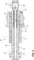
- a primary load path 36 may include the ball screw 14, the outer friction springs 22, the inner friction springs 20, the tie rod 16, and the bearing 26.
- loads may be transferred via the primary load path 36 (e.g., from the ball screw 14 to the outer friction springs 22, to the inner friction springs 20, to the tie rod 16, to the bearing 26, and into the aircraft structure).
- the primary load path 34 may not include portions of the tie rod 16 or the ball screw 14 between the first end 30 of the ball screw 14 and the friction springs 20, 22.
- the primary load path 36 may not include portions of the tie rod 16 or the ball screw 14 between the second end of the ball screw 14 and the friction springs 20, 22.
- the friction springs 20, 22 may no longer be compressed (or may be compressed to a lesser degree) and may not divert/transfer loads from the ball screw 14 to the tie rod 16.
- the gap 34 between the ball screw 14 and the bearing 26 may close, which may provide a visual indication of a failure in the primary load path 36.
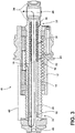
- the tie rod 16 may be intact and may be configured to maintain a connection between the actuator 10 and the aircraft structure 28 (e.g., loads may be transferred via a first secondary load path 40).
- the first secondary load path 40 may include the bearing 26, the tie rod 16, and/or an intact portion 42 of the ball screw 14, and may not include the friction springs 20, 22.
- the friction springs 20, 22 may not be compressed (or may be compressed to a lesser degree) and may not divert/transfer loads from the ball screw 14 to the tie rod 16.
- the gap 34 between the ball screw 14 and the bearing 26 may close, which may provide a visual indication of a failure in the primary load path 36.
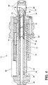
- the ball screw 14 may be intact and may be configured to maintain a connection between the actuator 10 and the aircraft structure (e.g., loads may be transferred via a second secondary load path 44).
- the second secondary load path 44 may include the bearing 26 and the ball screw 14, and may not include the friction springs 20, 22 or the tie rod 16.
- the friction springs 20, 22 may interconnect the primary load path 36 with the first secondary load path 40 and/or the second secondary load path 44, and may facilitate transition from the primary load 36 to the secondary load paths 40, 44 in the event of a failure of the ball screw 14 or the tie rod 16.
- references to a single element are not necessarily so limited and may include one or more of such element.
- Any directional references e.g., plus, minus, upper, lower, upward, downward, left, right, leftward, rightward, top, bottom, above, below, vertical, horizontal, clockwise, and counterclockwise
- Any directional references are only used for identification purposes to aid the reader's understanding of the present disclosure, and do not create limitations, particularly as to the position, orientation, or use of embodiments.
- joinder references are to be construed broadly and may include intermediate members between a connection of elements and relative movement between elements. As such, joinder references do not necessarily imply that two elements are directly connected/coupled and in fixed relation to each other.
- the use of "e.g.” in the specification is to be construed broadly and is used to provide non-limiting examples of embodiments of the disclosure, and the disclosure is not limited to such examples.
- Uses of "and” and “or” are to be construed broadly (e.g., to be treated as "and/or”). For example and without limitation, uses of "and” do not necessarily require all elements or features listed, and uses of "or” are intended to be inclusive unless such a construction would be illogical.
Landscapes
- Engineering & Computer Science (AREA)
- General Engineering & Computer Science (AREA)
- Mechanical Engineering (AREA)
- Transmission Devices (AREA)
Abstract
Description
- The present disclosure generally relates to linear actuators, including linear actuators that may be used in connection aircraft, such as with aircraft flaps, trim components, and/or stabilizers.
- This background description is set forth below for the purpose of providing context only. Therefore, any aspect of this background description, to the extent that it does not otherwise qualify as prior art, is neither expressly nor impliedly admitted as prior art against the instant disclosure.
- Some actuators do not provide any indication that primary or backup components have failed, and/or it may be difficult to determine if primary or backup components have failed.
- There is a desire for solutions/options that minimize or eliminate one or more challenges or shortcomings of linear actuators. The foregoing discussion is intended only to illustrate examples of the present field and should not be taken as a disavowal of scope.
- In embodiments, an actuator may include a housing, a ball screw engaged with the housing, a tie rod disposed in the ball screw, a plurality of friction springs in the ball screw and around the tie rod, and/or a bearing that may be interference fit with the tie rod and clearance fit with the ball screw.
- The foregoing and other aspects, features, details, utilities, and/or advantages of embodiments of the present disclosure will be apparent from reading the following description, and from reviewing the accompanying drawings.
-
-
FIG. 1 is a cross-sectional view generally illustrating an embodiment of a linear actuator according to teachings of the present disclosure. -
FIG. 2 is a cross-sectional view generally illustrating an embodiment of a linear actuator according to teachings of the present disclosure. -
FIG. 3 is a cross-sectional view generally illustrating an embodiment of a linear actuator with a fractured ball screw according to teachings of the present disclosure. -
FIG. 4 is a cross-sectional view generally illustrating an embodiment of a linear actuator with a fractured tie rod according to teachings of the present disclosure. -
FIG. 5 is a perspective view generally illustrating an embodiment of an inner friction spring of a linear actuator according to teachings of the present disclosure. -
FIG. 6 is a perspective view generally illustrating an embodiment of an outer friction spring of a linear actuator according to teachings of the present disclosure. - Reference will now be made in detail to embodiments of the present disclosure, examples of which are described herein and illustrated in the accompanying drawings. While the present disclosure will be described in conjunction with embodiments and/or examples, it will be understood that they are not intended to limit the present disclosure to these embodiments and/or examples. On the contrary, the present disclosure is intended to cover alternatives, modifications, and equivalents.
- In embodiments, such as generally illustrated in
FIGS. 1-4 , anactuator 10 may include ahousing 12, aball screw 14, atie rod 16, an adjustingnut 18, inner friction springs 20, outer friction springs 22, aspacer 24, and/or abearing 26. Theactuator 10 may be connected to anexternal component 28, such as an aircraft structure. - With embodiments, the
ball screw 14 may be disposed at least partially in thehousing 12. The ball screw 14 may be engaged with thehousing 12 such that rotation of one of theball screw 14 and the housing 12 (or one or more components thereof) may cause translation of the other of theball screw 14 and thehousing 12. The ball screw 12 may include afirst end 30 and asecond end 30. Thebearing 26 may be disposed at or about thesecond end 32 of theball screw 14. - In embodiments, the friction springs 20, 22 may be disposed in the
ball screw 14 and/or disposed around thetie rod 16. The friction springs 20, 22 may include one or more of a variety of shapes, sizes, configurations, and/or materials. For example and without limitation, as seen inFIGS. 5 and 6 , the friction springs 20, 22 may include C-shaped configurations. The outer friction springs 22 may include larger outer diameters than the inner friction springs 20. Theouter friction springs 22 and theinner friction springs 20 may be disposed in an alternating configuration along thetie rod 16. - With embodiments, a
spacer 24 may be disposed in theball screw 14 and may extend from the adjustingnut 18 to thefriction springs spacer 24 may be configured to facilitate compression/loading of thefriction springs - In embodiments, an
adjusting nut 18 may be disposed in theball screw 14, such as at or about thefirst end 30 of theball screw 14. The adjustingnut 18 may include external threads that may engage internal threads of the ball screw. The adjusting nut may be tightened, which may compress thefriction springs nut 18 may cause translation of thespacer 24, which may compress thefriction springs 20, 22). Compressing thefriction springs outer friction springs 22 expanding, which may generate an interference between theball screw 14 inner diameter, the outer diameter of theouter friction springs 22, and theinner friction springs 20. Theinner friction springs 20 may collapse, which may create interference between thetie rod 16 outer diameter, the inner friction springs 20, and theouter friction springs 20. - With embodiments, a
bearing 26 may be interference fit with thetie rod 16. Thebearing 26 may be clearance fit with theball screw 14. The clearance may provide agap 34 that may provide an indication of a failure of thetie rod 16 and/or of the ball screw 14 (e.g., if thegap 34 is no longer present). A ring may be disposed in thegap 34 between thebearing 26 and theball screw 14 to maintain the gap during loading of thefriction springs - In embodiments, such as generally illustrated in
FIG. 2 , aprimary load path 36 may include theball screw 14, theouter friction springs 22, theinner friction springs 20, thetie rod 16, and thebearing 26. During normal operation, loads may be transferred via the primary load path 36 (e.g., from theball screw 14 to theouter friction springs 22, to theinner friction springs 20, to thetie rod 16, to thebearing 26, and into the aircraft structure). Theprimary load path 34 may not include portions of thetie rod 16 or theball screw 14 between thefirst end 30 of theball screw 14 and thefriction springs primary load path 36 may not include portions of thetie rod 16 or theball screw 14 between the second end of theball screw 14 and thefriction springs - With embodiments, such as generally illustrated in
FIG. 3 , in the event of a failure of the ball screw 14 (e.g., one ormore fractures 38 along the ball screw 14), thefriction springs ball screw 14 to thetie rod 16. In such an event, thegap 34 between theball screw 14 and thebearing 26 may close, which may provide a visual indication of a failure in theprimary load path 36. Thetie rod 16 may be intact and may be configured to maintain a connection between theactuator 10 and the aircraft structure 28 (e.g., loads may be transferred via a first secondary load path 40). The firstsecondary load path 40 may include thebearing 26, thetie rod 16, and/or anintact portion 42 of theball screw 14, and may not include thefriction springs - In embodiments, such as generally illustrated in
FIG. 4 , in the event of a failure of the tie rod 16 (e.g., one ormore fractures 38 along the tie rod 16), thefriction springs ball screw 14 to thetie rod 16. In such an event, thegap 34 between theball screw 14 and thebearing 26 may close, which may provide a visual indication of a failure in theprimary load path 36. Theball screw 14 may be intact and may be configured to maintain a connection between theactuator 10 and the aircraft structure (e.g., loads may be transferred via a second secondary load path 44). The secondsecondary load path 44 may include thebearing 26 and theball screw 14, and may not include thefriction springs tie rod 16. - In embodiments, the
friction springs primary load path 36 with the firstsecondary load path 40 and/or the secondsecondary load path 44, and may facilitate transition from theprimary load 36 to thesecondary load paths ball screw 14 or thetie rod 16. - Various embodiments are described herein for various apparatuses, systems, and/or methods. Numerous specific details are set forth to provide a thorough understanding of the overall structure, function, manufacture, and use of the embodiments as described in the specification and illustrated in the accompanying drawings. It will be understood by those skilled in the art, however, that the embodiments may be practiced without such specific details. In other instances, well-known operations, components, and elements have not been described in detail so as not to obscure the embodiments described in the specification. Those of ordinary skill in the art will understand that the embodiments described and illustrated herein are non-limiting examples, and thus it can be appreciated that the specific structural and functional details disclosed herein may be representative and do not necessarily limit the scope of the embodiments.
- Reference throughout the specification to "various embodiments," "with embodiments," "in embodiments," or "an embodiment," or the like, means that a particular feature, structure, or characteristic described in connection with the embodiment is included in at least one embodiment. Thus, appearances of the phrases "in various embodiments," "with embodiments," "in embodiments," or "an embodiment," or the like, in places throughout the specification are not necessarily all referring to the same embodiment. Furthermore, the particular features, structures, or characteristics may be combined in any suitable manner in one or more embodiments. Thus, the particular features, structures, or characteristics illustrated or described in connection with one embodiment/example may be combined, in whole or in part, with the features, structures, functions, and/or characteristics of one or more other embodiments/examples without limitation given that such combination is not illogical or non-functional. Moreover, many modifications may be made to adapt a particular situation or material to the teachings of the present disclosure without departing from the scope thereof.
- It should be understood that references to a single element are not necessarily so limited and may include one or more of such element. Any directional references (e.g., plus, minus, upper, lower, upward, downward, left, right, leftward, rightward, top, bottom, above, below, vertical, horizontal, clockwise, and counterclockwise) are only used for identification purposes to aid the reader's understanding of the present disclosure, and do not create limitations, particularly as to the position, orientation, or use of embodiments.
- Joinder references (e.g., attached, coupled, connected, and the like) are to be construed broadly and may include intermediate members between a connection of elements and relative movement between elements. As such, joinder references do not necessarily imply that two elements are directly connected/coupled and in fixed relation to each other. The use of "e.g." in the specification is to be construed broadly and is used to provide non-limiting examples of embodiments of the disclosure, and the disclosure is not limited to such examples. Uses of "and" and "or" are to be construed broadly (e.g., to be treated as "and/or"). For example and without limitation, uses of "and" do not necessarily require all elements or features listed, and uses of "or" are intended to be inclusive unless such a construction would be illogical.
- While processes, systems, and methods may be described herein in connection with one or more steps in a particular sequence, it should be understood that such methods may be practiced with the steps in a different order, with certain steps performed simultaneously, with additional steps, and/or with certain described steps omitted.
- It is intended that all matter contained in the above description or shown in the accompanying drawings shall be interpreted as illustrative only and not limiting. Changes in detail or structure may be made without departing from the present disclosure.
Claims (15)
- An actuator, comprising:a housing;a ball screw engaged with the housing;a tie rod disposed in the ball screw;a plurality of friction springs in the ball screw and around the tie rod; anda bearing having an interference fit with the tie rod and a clearance fit with the ball screw.
- The actuator according to claim 1, wherein the plurality of friction springs includes a plurality of outer friction springs and a plurality of inner friction springs, the outer friction springs having an outer diameter greater than an outer diameter of the inner friction springs.
- The actuator according to claim 2, wherein the plurality of outer friction springs are arranged in an alternating configuration with the plurality of inner friction springs.
- The actuator according to claim 2, wherein the outer friction springs have an interference fit with the ball screw.
- The actuator according to claim 2, wherein the inner friction springs have an interference fit with the tie rod.
- The actuator according to claim 1, wherein each of the plurality of friction springs has a C-shaped configuration.
- The actuator according to claim 2, wherein the plurality of outer friction springs and the plurality of inner friction springs each has a C-shaped configuration.
- The actuator according to claim 1, further comprising a spacer disposed between the tie rod and the ball screw.
- The actuator according to claim 8, further comprising an adjusting nut disposed in the ball screw at or about an end thereof, the spacer being located between the adjusting nut and the plurality of friction springs.
- The actuator according to claim 9, wherein the adjusting nut has external threads configured to engage with internal threads of the ball screw to enable axial movement of the adjusting nut.
- A method comprising:compressing a plurality of outer friction springs to create an interference fit with an inner diameter of a ball screw;compressing a plurality of inner friction springs to create an interference fit with an outer diameter of a tie rod disposed within the ball screw;transferring a load via a primary load path during a normal operation; andtransferring the load via a first secondary load path when there is a fault with the ball screw, and via a second secondary load path when there is a fault with one of the tie rod;wherein the primary load path is from the ball screw to the outer friction springs, to the inner friction springs, to the tie rod, to a bearing, and into an external component;wherein the first secondary load path is from an intact portion of the ball screw to the tie rod, to the bearing, and into the external component;wherein the second secondary load path is from the ball screw to the bearing and into the external component; andwherein the bearing has an interference fit with the tie rod and clearance fit with the ball screw.
- The method according to claim 11, wherein the plurality of outer friction springs and the plurality of inner friction springs each has a C-shaped configuration.
- The method according to claim 11, wherein:compressing the plurality of outer friction springs includes expanding the outer friction springs in a radial direction to create the interference fit with the inner diameter of the ball screw; andcompressing the plurality of inner springs includes collapsing the inner friction springs in the radial direction to create the interference fit with the outer diameter of the tie rod.
- The method according to claim 11, wherein compressing the plurality of outer friction springs and compressing the plurality of inner friction springs is caused by moving an adjusting nut located at or about an end of the ball screw to press a spacer disposed between the ball screw and the tie rod against the plurality of outer friction springs and plurality of inner friction springs.
- The method according to claim 14, wherein the adjusting nut has external threads configured to engage with internal threads of the ball screw to enable axial movement of the adjusting nut.
Applications Claiming Priority (2)
| Application Number | Priority Date | Filing Date | Title |
|---|---|---|---|
| US201862739937P | 2018-10-02 | 2018-10-02 | |
| US16/585,112 US10955033B2 (en) | 2018-10-02 | 2019-09-27 | Linear actuator |
Publications (2)
| Publication Number | Publication Date |
|---|---|
| EP3633234A1 true EP3633234A1 (en) | 2020-04-08 |
| EP3633234B1 EP3633234B1 (en) | 2022-06-22 |
Family
ID=68136171
Family Applications (1)
| Application Number | Title | Priority Date | Filing Date |
|---|---|---|---|
| EP19200936.3A Active EP3633234B1 (en) | 2018-10-02 | 2019-10-01 | Linear actuator with alternate power path and a corresponding method |
Country Status (2)
| Country | Link |
|---|---|
| US (1) | US10955033B2 (en) |
| EP (1) | EP3633234B1 (en) |
Families Citing this family (2)
| Publication number | Priority date | Publication date | Assignee | Title |
|---|---|---|---|---|
| EP3524514A1 (en) * | 2018-02-09 | 2019-08-14 | Airbus Operations GmbH | Actuation unit for actuating a foldable wing tip portion of a wing for an aircraft |
| WO2019202691A1 (en) * | 2018-04-18 | 2019-10-24 | オリンパス株式会社 | Slide actuator |
Citations (2)
| Publication number | Priority date | Publication date | Assignee | Title |
|---|---|---|---|---|
| WO2011134799A1 (en) * | 2010-04-30 | 2011-11-03 | Goodrich Actuation Systems Sas | Device for detecting the breakage of a primary path in a flight control actuator |
| DE102011119946A1 (en) * | 2011-12-01 | 2013-06-06 | Liebherr-Aerospace Lindenberg Gmbh | Positioning device for positioning e.g. landing flap at fuselage of aircraft, has upper and lower gaps provided in load path, and detent unit of detent device penetrating into gaps when component of another load path is damaged |
Family Cites Families (18)
| Publication number | Priority date | Publication date | Assignee | Title |
|---|---|---|---|---|
| US3534626A (en) * | 1965-11-29 | 1970-10-20 | William I Elliott | Method and construction for cooperatively threaded parts |
| US4210033A (en) * | 1977-07-19 | 1980-07-01 | Kerk Motion Products, Inc. | Anti-backlash nut |
| JPS6257561U (en) * | 1985-09-30 | 1987-04-09 | ||
| IT210468Z2 (en) * | 1987-01-21 | 1988-12-30 | Iveco Fiat | ELECTROMECHANICAL LINEAR ACTUATOR FOR TILTING THE DRIVER'S CABIN OF AN INDUSTRIAL VEHICLE |
| US4974464A (en) * | 1988-03-17 | 1990-12-04 | Erikson Kenneth W | Motorized anti-backlash linear actuator |
| US6253657B1 (en) * | 1999-12-22 | 2001-07-03 | Trw Inc. | Steering apparatus |
| US6880424B2 (en) * | 2001-12-07 | 2005-04-19 | L & P Property Management Company | Apparatus for telescoping actuator |
| US8960031B2 (en) * | 2009-09-01 | 2015-02-24 | Parker-Hannifin Corporation | Aircraft stabilizer actuator |
| ES2872881T3 (en) * | 2012-06-04 | 2021-11-03 | Aerocontrolex Group Inc | Purge actuator assembly |
| EP2962005B1 (en) * | 2013-02-28 | 2018-10-17 | Per Stensgaard Innovasjon AS | Actuator |
| US10787195B2 (en) * | 2013-05-22 | 2020-09-29 | Jtekt Corporation | Electric power steering system |
| EP2896564B1 (en) * | 2014-01-21 | 2016-11-16 | CESA, Compania Espanola de Sistemas Aeronauticos, S.A. | Linear electromechanical actuator and anti-jamming device |
| CA3230952A1 (en) * | 2015-08-04 | 2017-02-09 | Kyntec Corporation | Mechanical spring actuator |
| US10611404B2 (en) * | 2015-10-22 | 2020-04-07 | Jtekt Corporation | Damper device and steering device |
| JP6534907B2 (en) * | 2015-10-22 | 2019-06-26 | 株式会社ジェイテクト | Damper apparatus and steering apparatus |
| US10024450B2 (en) * | 2015-11-25 | 2018-07-17 | Woodward, Inc. | High speed shutdown device for electric actuator |
| US10228046B2 (en) * | 2016-12-21 | 2019-03-12 | Caterpillar Inc. | Electric linear actuator having planetary gear arrangement |
| US10801594B2 (en) * | 2018-05-30 | 2020-10-13 | The Boeing Company | Screw actuator, aircraft comprising a screw actuator, and method of lifting a load |
-
2019
- 2019-09-27 US US16/585,112 patent/US10955033B2/en active Active
- 2019-10-01 EP EP19200936.3A patent/EP3633234B1/en active Active
Patent Citations (2)
| Publication number | Priority date | Publication date | Assignee | Title |
|---|---|---|---|---|
| WO2011134799A1 (en) * | 2010-04-30 | 2011-11-03 | Goodrich Actuation Systems Sas | Device for detecting the breakage of a primary path in a flight control actuator |
| DE102011119946A1 (en) * | 2011-12-01 | 2013-06-06 | Liebherr-Aerospace Lindenberg Gmbh | Positioning device for positioning e.g. landing flap at fuselage of aircraft, has upper and lower gaps provided in load path, and detent unit of detent device penetrating into gaps when component of another load path is damaged |
Also Published As
| Publication number | Publication date |
|---|---|
| US10955033B2 (en) | 2021-03-23 |
| EP3633234B1 (en) | 2022-06-22 |
| US20200103008A1 (en) | 2020-04-02 |
Similar Documents
| Publication | Publication Date | Title |
|---|---|---|
| EP3633234B1 (en) | Linear actuator with alternate power path and a corresponding method | |
| US10890237B2 (en) | Actuator with ball nut | |
| US10974811B2 (en) | Upper attachment for trimmable horizontal stabiliser actuator | |
| CN102906456B (en) | For be transformed into the equipment of axially-movable by rotatablely moving | |
| CN112081891B (en) | Actuator lower attachment | |
| US11300185B2 (en) | Actuator with backup component failure detection | |
| CN101825205A (en) | Connection set and the block ring device that is used for connection set | |
| US8910906B2 (en) | Articulable rotational coupling for an aircraft | |
| JP5002026B2 (en) | Actuator assembly structure of fluid control valve and fluid control valve formed by the structure | |
| US10099776B2 (en) | Rheologic fluid coupler for redundant linear electromechanical actuators | |
| US11274688B2 (en) | Composite laminate and load-introduction component for a load-introduction joint | |
| KR20170029392A (en) | A ball-bearing control cable, a mechanical system, and an aircraft | |
| EP3127805B1 (en) | Lower attachment for trimmable horizontal stabiliser actuator | |
| US10837531B2 (en) | Actuator | |
| US10518871B2 (en) | Crocodile-type flight control surface for aircraft with locking mechanism for additional stiffness | |
| WO2013011324A1 (en) | Pin joint assembly | |
| US8106556B2 (en) | Emergency rolling bearing that is insensitive to axial load | |
| CN207550209U (en) | A kind of steering framing wheel with rigidity adjustable structure is to radial direction mechanism | |
| US9915285B2 (en) | Universal joint with simplified structure | |
| CN108116441A (en) | A kind of steering framing wheel with rigidity adjustable structure is to radial direction mechanism | |
| US9920789B2 (en) | Universal joint with simplified structure | |
| JP5826871B2 (en) | Elastic joint for slide block adapter | |
| US20190366534A1 (en) | Robotic Arm Assembly | |
| US20120014741A1 (en) | Cushioned sliding joint | |
| US20150291211A1 (en) | Device for protecting against overloading |
Legal Events
| Date | Code | Title | Description |
|---|---|---|---|
| PUAI | Public reference made under article 153(3) epc to a published international application that has entered the european phase |
Free format text: ORIGINAL CODE: 0009012 |
|
| STAA | Information on the status of an ep patent application or granted ep patent |
Free format text: STATUS: REQUEST FOR EXAMINATION WAS MADE |
|
| 17P | Request for examination filed |
Effective date: 20191001 |
|
| AK | Designated contracting states |
Kind code of ref document: A1 Designated state(s): AL AT BE BG CH CY CZ DE DK EE ES FI FR GB GR HR HU IE IS IT LI LT LU LV MC MK MT NL NO PL PT RO RS SE SI SK SM TR |
|
| AX | Request for extension of the european patent |
Extension state: BA ME |
|
| GRAP | Despatch of communication of intention to grant a patent |
Free format text: ORIGINAL CODE: EPIDOSNIGR1 |
|
| STAA | Information on the status of an ep patent application or granted ep patent |
Free format text: STATUS: GRANT OF PATENT IS INTENDED |
|
| INTG | Intention to grant announced |
Effective date: 20220104 |
|
| GRAS | Grant fee paid |
Free format text: ORIGINAL CODE: EPIDOSNIGR3 |
|
| GRAA | (expected) grant |
Free format text: ORIGINAL CODE: 0009210 |
|
| STAA | Information on the status of an ep patent application or granted ep patent |
Free format text: STATUS: THE PATENT HAS BEEN GRANTED |
|
| AK | Designated contracting states |
Kind code of ref document: B1 Designated state(s): AL AT BE BG CH CY CZ DE DK EE ES FI FR GB GR HR HU IE IS IT LI LT LU LV MC MK MT NL NO PL PT RO RS SE SI SK SM TR |
|
| REG | Reference to a national code |
Ref country code: GB Ref legal event code: FG4D |
|
| REG | Reference to a national code |
Ref country code: CH Ref legal event code: EP |
|
| REG | Reference to a national code |
Ref country code: DE Ref legal event code: R082 Ref document number: 602019016105 Country of ref document: DE |
|
| REG | Reference to a national code |
Ref country code: DE Ref legal event code: R096 Ref document number: 602019016105 Country of ref document: DE |
|
| REG | Reference to a national code |
Ref country code: AT Ref legal event code: REF Ref document number: 1499965 Country of ref document: AT Kind code of ref document: T Effective date: 20220715 |
|
| REG | Reference to a national code |
Ref country code: IE Ref legal event code: FG4D |
|
| REG | Reference to a national code |
Ref country code: LT Ref legal event code: MG9D |
|
| REG | Reference to a national code |
Ref country code: NL Ref legal event code: MP Effective date: 20220622 |
|
| PG25 | Lapsed in a contracting state [announced via postgrant information from national office to epo] |
Ref country code: SE Free format text: LAPSE BECAUSE OF FAILURE TO SUBMIT A TRANSLATION OF THE DESCRIPTION OR TO PAY THE FEE WITHIN THE PRESCRIBED TIME-LIMIT Effective date: 20220622 Ref country code: NO Free format text: LAPSE BECAUSE OF FAILURE TO SUBMIT A TRANSLATION OF THE DESCRIPTION OR TO PAY THE FEE WITHIN THE PRESCRIBED TIME-LIMIT Effective date: 20220922 Ref country code: LT Free format text: LAPSE BECAUSE OF FAILURE TO SUBMIT A TRANSLATION OF THE DESCRIPTION OR TO PAY THE FEE WITHIN THE PRESCRIBED TIME-LIMIT Effective date: 20220622 Ref country code: HR Free format text: LAPSE BECAUSE OF FAILURE TO SUBMIT A TRANSLATION OF THE DESCRIPTION OR TO PAY THE FEE WITHIN THE PRESCRIBED TIME-LIMIT Effective date: 20220622 Ref country code: GR Free format text: LAPSE BECAUSE OF FAILURE TO SUBMIT A TRANSLATION OF THE DESCRIPTION OR TO PAY THE FEE WITHIN THE PRESCRIBED TIME-LIMIT Effective date: 20220923 Ref country code: FI Free format text: LAPSE BECAUSE OF FAILURE TO SUBMIT A TRANSLATION OF THE DESCRIPTION OR TO PAY THE FEE WITHIN THE PRESCRIBED TIME-LIMIT Effective date: 20220622 Ref country code: BG Free format text: LAPSE BECAUSE OF FAILURE TO SUBMIT A TRANSLATION OF THE DESCRIPTION OR TO PAY THE FEE WITHIN THE PRESCRIBED TIME-LIMIT Effective date: 20220922 |
|
| REG | Reference to a national code |
Ref country code: AT Ref legal event code: MK05 Ref document number: 1499965 Country of ref document: AT Kind code of ref document: T Effective date: 20220622 |
|
| PG25 | Lapsed in a contracting state [announced via postgrant information from national office to epo] |
Ref country code: RS Free format text: LAPSE BECAUSE OF FAILURE TO SUBMIT A TRANSLATION OF THE DESCRIPTION OR TO PAY THE FEE WITHIN THE PRESCRIBED TIME-LIMIT Effective date: 20220622 Ref country code: LV Free format text: LAPSE BECAUSE OF FAILURE TO SUBMIT A TRANSLATION OF THE DESCRIPTION OR TO PAY THE FEE WITHIN THE PRESCRIBED TIME-LIMIT Effective date: 20220622 |
|
| PGFP | Annual fee paid to national office [announced via postgrant information from national office to epo] |
Ref country code: FR Payment date: 20220920 Year of fee payment: 4 |
|
| PG25 | Lapsed in a contracting state [announced via postgrant information from national office to epo] |
Ref country code: NL Free format text: LAPSE BECAUSE OF FAILURE TO SUBMIT A TRANSLATION OF THE DESCRIPTION OR TO PAY THE FEE WITHIN THE PRESCRIBED TIME-LIMIT Effective date: 20220622 |
|
| PG25 | Lapsed in a contracting state [announced via postgrant information from national office to epo] |
Ref country code: SM Free format text: LAPSE BECAUSE OF FAILURE TO SUBMIT A TRANSLATION OF THE DESCRIPTION OR TO PAY THE FEE WITHIN THE PRESCRIBED TIME-LIMIT Effective date: 20220622 Ref country code: SK Free format text: LAPSE BECAUSE OF FAILURE TO SUBMIT A TRANSLATION OF THE DESCRIPTION OR TO PAY THE FEE WITHIN THE PRESCRIBED TIME-LIMIT Effective date: 20220622 Ref country code: RO Free format text: LAPSE BECAUSE OF FAILURE TO SUBMIT A TRANSLATION OF THE DESCRIPTION OR TO PAY THE FEE WITHIN THE PRESCRIBED TIME-LIMIT Effective date: 20220622 Ref country code: PT Free format text: LAPSE BECAUSE OF FAILURE TO SUBMIT A TRANSLATION OF THE DESCRIPTION OR TO PAY THE FEE WITHIN THE PRESCRIBED TIME-LIMIT Effective date: 20221024 Ref country code: ES Free format text: LAPSE BECAUSE OF FAILURE TO SUBMIT A TRANSLATION OF THE DESCRIPTION OR TO PAY THE FEE WITHIN THE PRESCRIBED TIME-LIMIT Effective date: 20220622 Ref country code: EE Free format text: LAPSE BECAUSE OF FAILURE TO SUBMIT A TRANSLATION OF THE DESCRIPTION OR TO PAY THE FEE WITHIN THE PRESCRIBED TIME-LIMIT Effective date: 20220622 Ref country code: CZ Free format text: LAPSE BECAUSE OF FAILURE TO SUBMIT A TRANSLATION OF THE DESCRIPTION OR TO PAY THE FEE WITHIN THE PRESCRIBED TIME-LIMIT Effective date: 20220622 Ref country code: AT Free format text: LAPSE BECAUSE OF FAILURE TO SUBMIT A TRANSLATION OF THE DESCRIPTION OR TO PAY THE FEE WITHIN THE PRESCRIBED TIME-LIMIT Effective date: 20220622 |
|
| PGFP | Annual fee paid to national office [announced via postgrant information from national office to epo] |
Ref country code: DE Payment date: 20220920 Year of fee payment: 4 |
|
| PG25 | Lapsed in a contracting state [announced via postgrant information from national office to epo] |
Ref country code: PL Free format text: LAPSE BECAUSE OF FAILURE TO SUBMIT A TRANSLATION OF THE DESCRIPTION OR TO PAY THE FEE WITHIN THE PRESCRIBED TIME-LIMIT Effective date: 20220622 Ref country code: IS Free format text: LAPSE BECAUSE OF FAILURE TO SUBMIT A TRANSLATION OF THE DESCRIPTION OR TO PAY THE FEE WITHIN THE PRESCRIBED TIME-LIMIT Effective date: 20221022 |
|
| REG | Reference to a national code |
Ref country code: DE Ref legal event code: R097 Ref document number: 602019016105 Country of ref document: DE |
|
| PG25 | Lapsed in a contracting state [announced via postgrant information from national office to epo] |
Ref country code: AL Free format text: LAPSE BECAUSE OF FAILURE TO SUBMIT A TRANSLATION OF THE DESCRIPTION OR TO PAY THE FEE WITHIN THE PRESCRIBED TIME-LIMIT Effective date: 20220622 |
|
| PG25 | Lapsed in a contracting state [announced via postgrant information from national office to epo] |
Ref country code: DK Free format text: LAPSE BECAUSE OF FAILURE TO SUBMIT A TRANSLATION OF THE DESCRIPTION OR TO PAY THE FEE WITHIN THE PRESCRIBED TIME-LIMIT Effective date: 20220622 |
|
| PLBE | No opposition filed within time limit |
Free format text: ORIGINAL CODE: 0009261 |
|
| STAA | Information on the status of an ep patent application or granted ep patent |
Free format text: STATUS: NO OPPOSITION FILED WITHIN TIME LIMIT |
|
| 26N | No opposition filed |
Effective date: 20230323 |
|
| PG25 | Lapsed in a contracting state [announced via postgrant information from national office to epo] |
Ref country code: MC Free format text: LAPSE BECAUSE OF FAILURE TO SUBMIT A TRANSLATION OF THE DESCRIPTION OR TO PAY THE FEE WITHIN THE PRESCRIBED TIME-LIMIT Effective date: 20220622 |
|
| REG | Reference to a national code |
Ref country code: CH Ref legal event code: PL |
|
| REG | Reference to a national code |
Ref country code: BE Ref legal event code: MM Effective date: 20221031 |
|
| P01 | Opt-out of the competence of the unified patent court (upc) registered |
Effective date: 20230521 |
|
| PG25 | Lapsed in a contracting state [announced via postgrant information from national office to epo] |
Ref country code: LU Free format text: LAPSE BECAUSE OF NON-PAYMENT OF DUE FEES Effective date: 20221001 |
|
| PG25 | Lapsed in a contracting state [announced via postgrant information from national office to epo] |
Ref country code: LI Free format text: LAPSE BECAUSE OF NON-PAYMENT OF DUE FEES Effective date: 20221031 Ref country code: CH Free format text: LAPSE BECAUSE OF NON-PAYMENT OF DUE FEES Effective date: 20221031 |
|
| PG25 | Lapsed in a contracting state [announced via postgrant information from national office to epo] |
Ref country code: SI Free format text: LAPSE BECAUSE OF FAILURE TO SUBMIT A TRANSLATION OF THE DESCRIPTION OR TO PAY THE FEE WITHIN THE PRESCRIBED TIME-LIMIT Effective date: 20220622 |
|
| PG25 | Lapsed in a contracting state [announced via postgrant information from national office to epo] |
Ref country code: BE Free format text: LAPSE BECAUSE OF NON-PAYMENT OF DUE FEES Effective date: 20221031 |
|
| PG25 | Lapsed in a contracting state [announced via postgrant information from national office to epo] |
Ref country code: IE Free format text: LAPSE BECAUSE OF NON-PAYMENT OF DUE FEES Effective date: 20221001 |
|
| PG25 | Lapsed in a contracting state [announced via postgrant information from national office to epo] |
Ref country code: IT Free format text: LAPSE BECAUSE OF FAILURE TO SUBMIT A TRANSLATION OF THE DESCRIPTION OR TO PAY THE FEE WITHIN THE PRESCRIBED TIME-LIMIT Effective date: 20220622 |
|
| PG25 | Lapsed in a contracting state [announced via postgrant information from national office to epo] |
Ref country code: HU Free format text: LAPSE BECAUSE OF FAILURE TO SUBMIT A TRANSLATION OF THE DESCRIPTION OR TO PAY THE FEE WITHIN THE PRESCRIBED TIME-LIMIT; INVALID AB INITIO Effective date: 20191001 |
|
| PG25 | Lapsed in a contracting state [announced via postgrant information from national office to epo] |
Ref country code: CY Free format text: LAPSE BECAUSE OF FAILURE TO SUBMIT A TRANSLATION OF THE DESCRIPTION OR TO PAY THE FEE WITHIN THE PRESCRIBED TIME-LIMIT Effective date: 20220622 |