EP3633219A2 - Bearing system with self-lubrication features, seals, grooves and slots for maintenance-free operation - Google Patents
Bearing system with self-lubrication features, seals, grooves and slots for maintenance-free operation Download PDFInfo
- Publication number
- EP3633219A2 EP3633219A2 EP19210097.2A EP19210097A EP3633219A2 EP 3633219 A2 EP3633219 A2 EP 3633219A2 EP 19210097 A EP19210097 A EP 19210097A EP 3633219 A2 EP3633219 A2 EP 3633219A2
- Authority
- EP
- European Patent Office
- Prior art keywords
- self
- leg
- lubricating
- facing surface
- extending
- Prior art date
- Legal status (The legal status is an assumption and is not a legal conclusion. Google has not performed a legal analysis and makes no representation as to the accuracy of the status listed.)
- Granted
Links
Images












Classifications
-
- F—MECHANICAL ENGINEERING; LIGHTING; HEATING; WEAPONS; BLASTING
- F16—ENGINEERING ELEMENTS AND UNITS; GENERAL MEASURES FOR PRODUCING AND MAINTAINING EFFECTIVE FUNCTIONING OF MACHINES OR INSTALLATIONS; THERMAL INSULATION IN GENERAL
- F16C—SHAFTS; FLEXIBLE SHAFTS; ELEMENTS OR CRANKSHAFT MECHANISMS; ROTARY BODIES OTHER THAN GEARING ELEMENTS; BEARINGS
- F16C17/00—Sliding-contact bearings for exclusively rotary movement
- F16C17/26—Systems consisting of a plurality of sliding-contact bearings
-
- B—PERFORMING OPERATIONS; TRANSPORTING
- B60—VEHICLES IN GENERAL
- B60D—VEHICLE CONNECTIONS
- B60D1/00—Traction couplings; Hitches; Draw-gear; Towing devices
- B60D1/14—Draw-gear or towing devices characterised by their type
-
- B—PERFORMING OPERATIONS; TRANSPORTING
- B60—VEHICLES IN GENERAL
- B60D—VEHICLE CONNECTIONS
- B60D1/00—Traction couplings; Hitches; Draw-gear; Towing devices
- B60D1/58—Auxiliary devices
- B60D1/586—Lubrication means
-
- F—MECHANICAL ENGINEERING; LIGHTING; HEATING; WEAPONS; BLASTING
- F16—ENGINEERING ELEMENTS AND UNITS; GENERAL MEASURES FOR PRODUCING AND MAINTAINING EFFECTIVE FUNCTIONING OF MACHINES OR INSTALLATIONS; THERMAL INSULATION IN GENERAL
- F16C—SHAFTS; FLEXIBLE SHAFTS; ELEMENTS OR CRANKSHAFT MECHANISMS; ROTARY BODIES OTHER THAN GEARING ELEMENTS; BEARINGS
- F16C11/00—Pivots; Pivotal connections
- F16C11/04—Pivotal connections
- F16C11/045—Pivotal connections with at least a pair of arms pivoting relatively to at least one other arm, all arms being mounted on one pin
-
- F—MECHANICAL ENGINEERING; LIGHTING; HEATING; WEAPONS; BLASTING
- F16—ENGINEERING ELEMENTS AND UNITS; GENERAL MEASURES FOR PRODUCING AND MAINTAINING EFFECTIVE FUNCTIONING OF MACHINES OR INSTALLATIONS; THERMAL INSULATION IN GENERAL
- F16C—SHAFTS; FLEXIBLE SHAFTS; ELEMENTS OR CRANKSHAFT MECHANISMS; ROTARY BODIES OTHER THAN GEARING ELEMENTS; BEARINGS
- F16C17/00—Sliding-contact bearings for exclusively rotary movement
- F16C17/02—Sliding-contact bearings for exclusively rotary movement for radial load only
-
- F—MECHANICAL ENGINEERING; LIGHTING; HEATING; WEAPONS; BLASTING
- F16—ENGINEERING ELEMENTS AND UNITS; GENERAL MEASURES FOR PRODUCING AND MAINTAINING EFFECTIVE FUNCTIONING OF MACHINES OR INSTALLATIONS; THERMAL INSULATION IN GENERAL
- F16C—SHAFTS; FLEXIBLE SHAFTS; ELEMENTS OR CRANKSHAFT MECHANISMS; ROTARY BODIES OTHER THAN GEARING ELEMENTS; BEARINGS
- F16C17/00—Sliding-contact bearings for exclusively rotary movement
- F16C17/04—Sliding-contact bearings for exclusively rotary movement for axial load only
-
- F—MECHANICAL ENGINEERING; LIGHTING; HEATING; WEAPONS; BLASTING
- F16—ENGINEERING ELEMENTS AND UNITS; GENERAL MEASURES FOR PRODUCING AND MAINTAINING EFFECTIVE FUNCTIONING OF MACHINES OR INSTALLATIONS; THERMAL INSULATION IN GENERAL
- F16C—SHAFTS; FLEXIBLE SHAFTS; ELEMENTS OR CRANKSHAFT MECHANISMS; ROTARY BODIES OTHER THAN GEARING ELEMENTS; BEARINGS
- F16C17/00—Sliding-contact bearings for exclusively rotary movement
- F16C17/04—Sliding-contact bearings for exclusively rotary movement for axial load only
- F16C17/045—Sliding-contact bearings for exclusively rotary movement for axial load only with grooves in the bearing surface to generate hydrodynamic pressure, e.g. spiral groove thrust bearings
-
- F—MECHANICAL ENGINEERING; LIGHTING; HEATING; WEAPONS; BLASTING
- F16—ENGINEERING ELEMENTS AND UNITS; GENERAL MEASURES FOR PRODUCING AND MAINTAINING EFFECTIVE FUNCTIONING OF MACHINES OR INSTALLATIONS; THERMAL INSULATION IN GENERAL
- F16C—SHAFTS; FLEXIBLE SHAFTS; ELEMENTS OR CRANKSHAFT MECHANISMS; ROTARY BODIES OTHER THAN GEARING ELEMENTS; BEARINGS
- F16C17/00—Sliding-contact bearings for exclusively rotary movement
- F16C17/04—Sliding-contact bearings for exclusively rotary movement for axial load only
- F16C17/06—Sliding-contact bearings for exclusively rotary movement for axial load only with tiltably-supported segments, e.g. Michell bearings
- F16C17/065—Sliding-contact bearings for exclusively rotary movement for axial load only with tiltably-supported segments, e.g. Michell bearings the segments being integrally formed with, or rigidly fixed to, a support-element
-
- F—MECHANICAL ENGINEERING; LIGHTING; HEATING; WEAPONS; BLASTING
- F16—ENGINEERING ELEMENTS AND UNITS; GENERAL MEASURES FOR PRODUCING AND MAINTAINING EFFECTIVE FUNCTIONING OF MACHINES OR INSTALLATIONS; THERMAL INSULATION IN GENERAL
- F16C—SHAFTS; FLEXIBLE SHAFTS; ELEMENTS OR CRANKSHAFT MECHANISMS; ROTARY BODIES OTHER THAN GEARING ELEMENTS; BEARINGS
- F16C17/00—Sliding-contact bearings for exclusively rotary movement
- F16C17/04—Sliding-contact bearings for exclusively rotary movement for axial load only
- F16C17/08—Sliding-contact bearings for exclusively rotary movement for axial load only for supporting the end face of a shaft or other member, e.g. footstep bearings
-
- F—MECHANICAL ENGINEERING; LIGHTING; HEATING; WEAPONS; BLASTING
- F16—ENGINEERING ELEMENTS AND UNITS; GENERAL MEASURES FOR PRODUCING AND MAINTAINING EFFECTIVE FUNCTIONING OF MACHINES OR INSTALLATIONS; THERMAL INSULATION IN GENERAL
- F16C—SHAFTS; FLEXIBLE SHAFTS; ELEMENTS OR CRANKSHAFT MECHANISMS; ROTARY BODIES OTHER THAN GEARING ELEMENTS; BEARINGS
- F16C33/00—Parts of bearings; Special methods for making bearings or parts thereof
- F16C33/02—Parts of sliding-contact bearings
- F16C33/04—Brasses; Bushes; Linings
- F16C33/06—Sliding surface mainly made of metal
- F16C33/10—Construction relative to lubrication
- F16C33/1025—Construction relative to lubrication with liquid, e.g. oil, as lubricant
- F16C33/103—Construction relative to lubrication with liquid, e.g. oil, as lubricant retained in or near the bearing
- F16C33/104—Construction relative to lubrication with liquid, e.g. oil, as lubricant retained in or near the bearing in a porous body, e.g. oil impregnated sintered sleeve
-
- F—MECHANICAL ENGINEERING; LIGHTING; HEATING; WEAPONS; BLASTING
- F16—ENGINEERING ELEMENTS AND UNITS; GENERAL MEASURES FOR PRODUCING AND MAINTAINING EFFECTIVE FUNCTIONING OF MACHINES OR INSTALLATIONS; THERMAL INSULATION IN GENERAL
- F16C—SHAFTS; FLEXIBLE SHAFTS; ELEMENTS OR CRANKSHAFT MECHANISMS; ROTARY BODIES OTHER THAN GEARING ELEMENTS; BEARINGS
- F16C33/00—Parts of bearings; Special methods for making bearings or parts thereof
- F16C33/02—Parts of sliding-contact bearings
- F16C33/04—Brasses; Bushes; Linings
- F16C33/06—Sliding surface mainly made of metal
- F16C33/10—Construction relative to lubrication
- F16C33/1025—Construction relative to lubrication with liquid, e.g. oil, as lubricant
- F16C33/1045—Details of supply of the liquid to the bearing
- F16C33/1055—Details of supply of the liquid to the bearing from radial inside, e.g. via a passage through the shaft and/or inner sleeve
-
- F—MECHANICAL ENGINEERING; LIGHTING; HEATING; WEAPONS; BLASTING
- F16—ENGINEERING ELEMENTS AND UNITS; GENERAL MEASURES FOR PRODUCING AND MAINTAINING EFFECTIVE FUNCTIONING OF MACHINES OR INSTALLATIONS; THERMAL INSULATION IN GENERAL
- F16C—SHAFTS; FLEXIBLE SHAFTS; ELEMENTS OR CRANKSHAFT MECHANISMS; ROTARY BODIES OTHER THAN GEARING ELEMENTS; BEARINGS
- F16C33/00—Parts of bearings; Special methods for making bearings or parts thereof
- F16C33/02—Parts of sliding-contact bearings
- F16C33/04—Brasses; Bushes; Linings
- F16C33/06—Sliding surface mainly made of metal
- F16C33/10—Construction relative to lubrication
- F16C33/1025—Construction relative to lubrication with liquid, e.g. oil, as lubricant
- F16C33/106—Details of distribution or circulation inside the bearings, e.g. details of the bearing surfaces to affect flow or pressure of the liquid
- F16C33/108—Details of distribution or circulation inside the bearings, e.g. details of the bearing surfaces to affect flow or pressure of the liquid with a plurality of elements forming the bearing surfaces, e.g. bearing pads
-
- F—MECHANICAL ENGINEERING; LIGHTING; HEATING; WEAPONS; BLASTING
- F16—ENGINEERING ELEMENTS AND UNITS; GENERAL MEASURES FOR PRODUCING AND MAINTAINING EFFECTIVE FUNCTIONING OF MACHINES OR INSTALLATIONS; THERMAL INSULATION IN GENERAL
- F16C—SHAFTS; FLEXIBLE SHAFTS; ELEMENTS OR CRANKSHAFT MECHANISMS; ROTARY BODIES OTHER THAN GEARING ELEMENTS; BEARINGS
- F16C33/00—Parts of bearings; Special methods for making bearings or parts thereof
- F16C33/02—Parts of sliding-contact bearings
- F16C33/04—Brasses; Bushes; Linings
- F16C33/06—Sliding surface mainly made of metal
- F16C33/10—Construction relative to lubrication
- F16C33/1095—Construction relative to lubrication with solids as lubricant, e.g. dry coatings, powder
-
- F—MECHANICAL ENGINEERING; LIGHTING; HEATING; WEAPONS; BLASTING
- F16—ENGINEERING ELEMENTS AND UNITS; GENERAL MEASURES FOR PRODUCING AND MAINTAINING EFFECTIVE FUNCTIONING OF MACHINES OR INSTALLATIONS; THERMAL INSULATION IN GENERAL
- F16C—SHAFTS; FLEXIBLE SHAFTS; ELEMENTS OR CRANKSHAFT MECHANISMS; ROTARY BODIES OTHER THAN GEARING ELEMENTS; BEARINGS
- F16C33/00—Parts of bearings; Special methods for making bearings or parts thereof
- F16C33/02—Parts of sliding-contact bearings
- F16C33/04—Brasses; Bushes; Linings
- F16C33/20—Sliding surface consisting mainly of plastics
-
- F—MECHANICAL ENGINEERING; LIGHTING; HEATING; WEAPONS; BLASTING
- F16—ENGINEERING ELEMENTS AND UNITS; GENERAL MEASURES FOR PRODUCING AND MAINTAINING EFFECTIVE FUNCTIONING OF MACHINES OR INSTALLATIONS; THERMAL INSULATION IN GENERAL
- F16C—SHAFTS; FLEXIBLE SHAFTS; ELEMENTS OR CRANKSHAFT MECHANISMS; ROTARY BODIES OTHER THAN GEARING ELEMENTS; BEARINGS
- F16C33/00—Parts of bearings; Special methods for making bearings or parts thereof
- F16C33/72—Sealings
- F16C33/74—Sealings of sliding-contact bearings
-
- F—MECHANICAL ENGINEERING; LIGHTING; HEATING; WEAPONS; BLASTING
- F16—ENGINEERING ELEMENTS AND UNITS; GENERAL MEASURES FOR PRODUCING AND MAINTAINING EFFECTIVE FUNCTIONING OF MACHINES OR INSTALLATIONS; THERMAL INSULATION IN GENERAL
- F16C—SHAFTS; FLEXIBLE SHAFTS; ELEMENTS OR CRANKSHAFT MECHANISMS; ROTARY BODIES OTHER THAN GEARING ELEMENTS; BEARINGS
- F16C2208/00—Plastics; Synthetic resins, e.g. rubbers
- F16C2208/02—Plastics; Synthetic resins, e.g. rubbers comprising fillers, fibres
- F16C2208/04—Glass fibres
-
- F—MECHANICAL ENGINEERING; LIGHTING; HEATING; WEAPONS; BLASTING
- F16—ENGINEERING ELEMENTS AND UNITS; GENERAL MEASURES FOR PRODUCING AND MAINTAINING EFFECTIVE FUNCTIONING OF MACHINES OR INSTALLATIONS; THERMAL INSULATION IN GENERAL
- F16C—SHAFTS; FLEXIBLE SHAFTS; ELEMENTS OR CRANKSHAFT MECHANISMS; ROTARY BODIES OTHER THAN GEARING ELEMENTS; BEARINGS
- F16C2208/00—Plastics; Synthetic resins, e.g. rubbers
- F16C2208/20—Thermoplastic resins
-
- F—MECHANICAL ENGINEERING; LIGHTING; HEATING; WEAPONS; BLASTING
- F16—ENGINEERING ELEMENTS AND UNITS; GENERAL MEASURES FOR PRODUCING AND MAINTAINING EFFECTIVE FUNCTIONING OF MACHINES OR INSTALLATIONS; THERMAL INSULATION IN GENERAL
- F16C—SHAFTS; FLEXIBLE SHAFTS; ELEMENTS OR CRANKSHAFT MECHANISMS; ROTARY BODIES OTHER THAN GEARING ELEMENTS; BEARINGS
- F16C2208/00—Plastics; Synthetic resins, e.g. rubbers
- F16C2208/20—Thermoplastic resins
- F16C2208/30—Fluoropolymers
- F16C2208/32—Polytetrafluorethylene [PTFE]
-
- F—MECHANICAL ENGINEERING; LIGHTING; HEATING; WEAPONS; BLASTING
- F16—ENGINEERING ELEMENTS AND UNITS; GENERAL MEASURES FOR PRODUCING AND MAINTAINING EFFECTIVE FUNCTIONING OF MACHINES OR INSTALLATIONS; THERMAL INSULATION IN GENERAL
- F16C—SHAFTS; FLEXIBLE SHAFTS; ELEMENTS OR CRANKSHAFT MECHANISMS; ROTARY BODIES OTHER THAN GEARING ELEMENTS; BEARINGS
- F16C2208/00—Plastics; Synthetic resins, e.g. rubbers
- F16C2208/20—Thermoplastic resins
- F16C2208/40—Imides, e.g. polyimide [PI], polyetherimide [PEI]
-
- F—MECHANICAL ENGINEERING; LIGHTING; HEATING; WEAPONS; BLASTING
- F16—ENGINEERING ELEMENTS AND UNITS; GENERAL MEASURES FOR PRODUCING AND MAINTAINING EFFECTIVE FUNCTIONING OF MACHINES OR INSTALLATIONS; THERMAL INSULATION IN GENERAL
- F16C—SHAFTS; FLEXIBLE SHAFTS; ELEMENTS OR CRANKSHAFT MECHANISMS; ROTARY BODIES OTHER THAN GEARING ELEMENTS; BEARINGS
- F16C2208/00—Plastics; Synthetic resins, e.g. rubbers
- F16C2208/80—Thermosetting resins
- F16C2208/90—Phenolic resin
-
- F—MECHANICAL ENGINEERING; LIGHTING; HEATING; WEAPONS; BLASTING
- F16—ENGINEERING ELEMENTS AND UNITS; GENERAL MEASURES FOR PRODUCING AND MAINTAINING EFFECTIVE FUNCTIONING OF MACHINES OR INSTALLATIONS; THERMAL INSULATION IN GENERAL
- F16C—SHAFTS; FLEXIBLE SHAFTS; ELEMENTS OR CRANKSHAFT MECHANISMS; ROTARY BODIES OTHER THAN GEARING ELEMENTS; BEARINGS
- F16C2326/00—Articles relating to transporting
-
- F—MECHANICAL ENGINEERING; LIGHTING; HEATING; WEAPONS; BLASTING
- F16—ENGINEERING ELEMENTS AND UNITS; GENERAL MEASURES FOR PRODUCING AND MAINTAINING EFFECTIVE FUNCTIONING OF MACHINES OR INSTALLATIONS; THERMAL INSULATION IN GENERAL
- F16C—SHAFTS; FLEXIBLE SHAFTS; ELEMENTS OR CRANKSHAFT MECHANISMS; ROTARY BODIES OTHER THAN GEARING ELEMENTS; BEARINGS
- F16C2326/00—Articles relating to transporting
- F16C2326/01—Parts of vehicles in general
-
- F—MECHANICAL ENGINEERING; LIGHTING; HEATING; WEAPONS; BLASTING
- F16—ENGINEERING ELEMENTS AND UNITS; GENERAL MEASURES FOR PRODUCING AND MAINTAINING EFFECTIVE FUNCTIONING OF MACHINES OR INSTALLATIONS; THERMAL INSULATION IN GENERAL
- F16C—SHAFTS; FLEXIBLE SHAFTS; ELEMENTS OR CRANKSHAFT MECHANISMS; ROTARY BODIES OTHER THAN GEARING ELEMENTS; BEARINGS
- F16C2326/00—Articles relating to transporting
- F16C2326/20—Land vehicles
-
- F—MECHANICAL ENGINEERING; LIGHTING; HEATING; WEAPONS; BLASTING
- F16—ENGINEERING ELEMENTS AND UNITS; GENERAL MEASURES FOR PRODUCING AND MAINTAINING EFFECTIVE FUNCTIONING OF MACHINES OR INSTALLATIONS; THERMAL INSULATION IN GENERAL
- F16C—SHAFTS; FLEXIBLE SHAFTS; ELEMENTS OR CRANKSHAFT MECHANISMS; ROTARY BODIES OTHER THAN GEARING ELEMENTS; BEARINGS
- F16C2350/00—Machines or articles related to building
- F16C2350/26—Excavators
Definitions
- This invention relates to a maintenance-free bearing system having self-lubricating features, seals, grooves and slots for use in a cushion hitch assembly for a hitch pull scraper vehicle, and is more particularly related to an interconnected bearing linkage system having two or more horizontal two-axis combined journal and thrust bearings with self-lubricating liners therein, two or more vertical single-axis sleeve bearings with self-lubricating liners therein and one or more vertical thrust bearing with self-lubricating liners therein, that cooperate with one another to accommodate vertical and horizontal angular movement relative to one another.
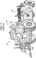
- a hitch pull type scraper 100 includes a pulling portion 101 such as a diesel engine powered cab or cabin.
- a scraper bowl 102 is coupled to the pulling portion (e.g., a cab or cabin) 101 by a hitch assembly 103.
- the hitch assembly 103 includes two H-links each having two journal bearings therein having a common shaft and another two journal bearings having another common shaft. The H-links moveably couple a linkage structure to a portion of the pulling portion 101.
- the hitch assembly 103 includes two vertical journal bearings disposed in a housing. Above one of the journal bearings is a thrust bearing.
- the two vertical journal bearings each employ a bronze sleeve disposed between a shaft and an interior surface defined by a bore in housing to facilitate rotational movement between the shaft and the housing.
- the thrust bearing employs a bronze bearing plate disposed therein to accommodate rotational movement of an upper thrust plate relative to a lower thrust plate.
- a grease supply system (e.g., a configuration of tubes, valves and pressurizing devices) injects grease between the upper thrust plate and the lower thrust plate and the bronze bearing plate to maintain lubrication therebetween.
- the grease supply system also supplies grease to the sleeve in the journal bearings.
- the grease supply system can be damaged by projectiles such as rocks and stones that are propelled by the movement of the scraper 100.
- Use of a grease supply system leads to several undesired effects such as: 1) increased power requirements for the vehicle; 2) increased capital cost and maintenance related costs; and 3) environmental impact when old grease is purged from bearings, for example grease can seep out of the bearings during re-lubrication or due to leakage and can fall onto the ground.
- damage of the grease supply system can cause the flow of grease to the thrust bearing and journal bearings to cease and create undesirable grease discharge to the environment.
- a bearing system for a hitch assembly for a heavy load capacity vehicle e.g., a scraper bowl 102 hitched (via the hitch assembly 103) to and pulled by a diesel engine power cabin or cab 100, as shown in FIG. 1
- a bearing system for a hitch assembly for a heavy load capacity vehicle e.g., a scraper bowl 102 hitched (via the hitch assembly 103) to and pulled by a diesel engine power cabin or cab 100, as shown in FIG. 1
- a bearing system for a hitch assembly for a heavy load capacity vehicle e.g., a scraper bowl 102 hitched (via the hitch assembly 103) to and pulled by a diesel engine power cabin or cab 100, as shown in FIG. 1
- 1000 a bearing system for a hitch assembly for a heavy load capacity vehicle
- the bearing system 1000 includes a linkage structure having three links, for example: 1) a cabin support link 101A (e.g., a support structure) extending from the cabin 101; 2) a bowl support link 102A (e.g., a support structure); and 3) a connector link 103A (e.g., a support structure) that moveably couples the cabin support link 101A to the bowl support link 102A to allow rotational movement in two or more axes of rotation (e.g., horizontal and vertical).
- a piston cylinder assembly 103P is coupled to the cabin support link 101A and the connector link 103A.
- the bearing system includes: 1) a first journal bearing assembly 200 that is moveably secured to the cabin support link 101A and the connector link 103A; 2) a second journal bearing assembly 300 is moveably secured to the cabin support link 101A and the connector link 103A; 3) a third journal bearing assembly 400 moveably secured to the connector link 103A and the bowl support link 102A; 4) a fourth journal bearing assembly 500 moveably secured to the connector link 103A and the bowl support link 102A; and 5) a thrust bearing assembly 600 disposed above the fourth journal bearing assembly 500 and between the connector link 103A and the bowl support link 102A.
- one or more seals, as described herein, are disposed in one or more of the first journal bearing assembly 200, the second journal bearing assembly 300, the third journal bearing assembly 400, the fourth journal bearing assembly 500 and the thrust bearing assembly 600.
- the first journal bearing assembly is generally designated by the number 200.
- the first journal bearing assembly 200 (e.g., an H-link assembly as shown in FIG. 3 ) includes four self-lubricating sleeve assemblies 10 (see FIG. 5 ) disposed therein and an end cap (212, 12 in FIG. 6 ) positioned on an axial end of each of four positions on the first journal bearing assembly 200.
- the thrust bearing end caps 212 each have a self-lubricating pad 8 (See FIG. 6 ) disposed on an axially inward facing surface thereof. While the thrust bearing end caps are shown and described herein, the present invention is not limited in this regard, as other configurations may apply, including, but not limited to, those with integrally sealed or welded ends, or with no end caps or partial end caps.
- each of the self-lubricating sleeve assemblies 10 includes an outer sleeve 50 with a self-lubricating sleeve 58 secured (e.g., via an adhesive such as epoxy or phenolic resin) to an interior surface of the outer sleeve 50, as described further herein.
- the second journal bearing assembly 300 (e.g., an H-link assembly as shown in FIG. 3 ) includes four of the self-lubricating sleeve assemblies 10 (see FIG. 5 ) disposed therein and one of the end caps (312, 12 in FIG. 6 ) positioned on an axial end of each of four positions on the second journal bearing assembly 300.
- the end caps 312 each have one of the self-lubricating pads 8 (see FIG. 6 ) disposed on the axially inward facing surface thereof.
- the third journal bearing assembly 400 includes one of the self-lubricating sleeve assemblies 10 (see FIG. 5 ) disposed therein.
- the fourth journal bearing assembly 500 includes one of the self-lubricating sleeve assemblies 10 (see FIG. 5 ) disposed therein.
- the thrust bearing assembly 600 is disposed around the fourth journal bearing assembly 500 and includes a self-lubricating cartridge 14 (see FIG. 10 ) disposed on at least one axially facing surface thereof.
- the first journal bearing assembly 200 is mounted in a first housing 216 (e.g., a body portion of the H-link).
- the first housing 216 includes a first leg 218A and a second leg 218B spaced apart from and centrally coupled to one another by a joint 219.
- a first bore 220 extends through the first leg 218A and the second leg 218B.
- One of the self-lubricating sleeve assemblies 10 (see FIG. 5 ) is secured in the first bore 220 of each of the first leg 218A and the second leg 218B.
- a first shaft 222 extends into and rotatingly engages a radially inward facing surface of each of the self-lubricating sleeves 58 in the first bore 220 of each of the first leg 218A and the second leg 218B.
- the first shaft 222 is configured to receive a first hub 101H1 (as shown in FIG. 2 ) therearound and between the first leg 218A and the second leg 218B.
- the first hub 101H1 extends from the cabin support link 101A.
- a thrust bearing end cap 212 is removably secured (e.g., via bolting) to an axially outward facing surface 200F of each the first housing 216 outside of the first bore 220 of the each of the first leg 218A and the second leg 218B.
- each of the end caps 212 incudes a self-lubricating pad 8 secured thereto for sliding engagement with a respective axial end of the first shaft 222.
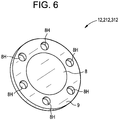
- the self-lubricating pad 8 is centrally located between a circular pattern of bolt holes 8H, as shown in FIG. 6 .
- a second bore 221 extends through the first leg 212A and the second leg 212B.
- One of the self-lubricating sleeve assemblies 10 (see FIG. 5 ) is secured in the second bore 221 of each of the first leg 218A and the second leg 218B.
- a second shaft 223 extends into and rotatingly engages an axially inward facing surface of each of the self-lubricating pads 8 in the first bore 220 of each of the first leg 218A and the second leg 218B.
- the second shaft 223 is configured to receive a pair of second hubs 103H1A and 103H1B therearound (as shown in FIG. 2 ) and between the first leg 218A and the second leg 218B.
- the pair of second hubs 103H1A and 103H1B extend from the connector link 103A.
- a thrust bearing end cap 212 is removably secured (e.g., via bolting) to an axially outward facing surface 200F of each the first housing 216 outside of the second bore 221 of the each of the first leg 218A and the second leg 218B.
- each of the end caps 212 incudes a self-lubricating pad 8 secured thereto for sliding engagement with a respective axial end 223E of the first shaft 223, as shown in FIG. 3 .
- the self-lubricating pad 8 is centrally located between a circular pattern of bolt holes 8H.
- a piston hub 103PA extends from the piston cylinder assembly 103P and has a bore therein in which the shaft 223 extends.
- the piston hub 103PA is positioned between the pair of second hubs 103H1A and 103H1B, as shown in FIG 4 .
- the second journal bearing assembly 300 is mounted in a second housing 316 (e.g., a body portion of the H-link).
- the second housing 316 includes a first leg 318A and a second leg 318B spaced apart from and centrally coupled to one another by a joint 319.
- a third bore 320 extends through the first leg 318A and the second leg 318B.
- One of the self-lubricating sleeves 10 (see FIG. 5 ) is secured in the third bore 320 of each of the first leg 318A and the second leg 318B.
- a third shaft 322 extends into and rotatingly engages a radially inward facing surface of each of the self-lubricating sleeves 58 in the third bore 320 of each of the first leg 318A and the second leg 318B.
- the third shaft 322 is configured to receive a third hub 101H2 therearound and between the first leg 318A and the second leg 318B.
- the third hub 101H2 extends from the cabin support link 101A.
- a thrust bearing end cap 312 is removably secured (e.g., via bolting) to an axially outward facing surface 300F of the second housing 316 outside of the third bore 320 of the each of the first leg 318A and the second leg 318B. As shown in FIG. 6 , each of the end caps 312 incudes a self-lubricating pad 8 secured thereto for sliding engagement with a respective axial end 322E of the third shaft 322. The self-lubricating pad 8 is centrally located between a circular pattern of bolt holes 8H.
- a second bore 321 extends through the first leg 318A and the second leg 318B.
- One of the self-lubricating sleeves 10 (see FIG. 5 ) is secured in the second bore 321 of each of the first leg 318A and the second leg 318B.
- a fourth shaft 323 extends into and rotatingly engages a radially inward facing surface of each of the self-lubricating sleeves 58 in the first bore 320 of each of the first leg 318A and the second leg 318B.
- the fourth shaft 323 is configured to receive a fourth hub 103H2 therearound and between the first leg 318A and the second leg 318B.
- the fourth hub 103H2 extends from the connector link 103A.
- a thrust bearing end cap 312 is removably secured (e.g., via bolting) to an axially outward facing surface 300F of each the second housing 316 outside of the fourth bore 321 of the each of the first leg 318A and the second leg 318B.
- each of the end caps 312 incudes a self-lubricating pad 8 secured thereto for sliding engagement with a respective axial end 322E of the fourth shaft 323.
- the self-lubricating pad 8 is centrally located between a circular pattern of bolt holes 8H.
- a third journal bearing assembly 400 (e.g., a vertical journal bearing assembly) is mounted in a third housing 102H1.
- the third housing 102H1 extends from the bowl support link 102A and is positioned between a fifth leg 103L5 and a sixth leg 103L6 each extending from the connector link 103A.
- a fifth bore 425 extends through the third housing 102H1, the fifth leg 103L5 and the sixth leg 103L6.
- One of the self-lubricating sleeves 8 is secured in the fifth bore 425.
- a fifth shaft 435 extends into and rotatingly engages a radially inward facing surface of the self-lubricating sleeve 58.
- a fourth journal bearing assembly 500 (e.g., a vertical journal bearing assembly) is mounted in a fourth housing 103H3.
- the fourth housing 103H3 extends from the connector link 103A and is positioned between a seventh leg 102L7 and an eighth leg 102L8 each extending from the bowl support link 102A.
- a sixth bore 526 extends through the fourth housing 103H3, the seventh leg 102L7 and the eighth leg 102L8.
- One of the self-lubricating sleeve assemblies 10 is secured in the fifth bore 435.
- a sixth shaft 536 extends into and rotatingly engages a radially inward facing surface of the self-lubricating sleeve 8.
- the fourth housing 103H3 has an annular recess 529 formed therein.
- a thrust bearing cartridge 14 is positioned in the annular recess 529, between the seventh leg 102L7 and the fourth housing 103H3.
- the thrust bearing cartridge 14 includes one or more self-lubricating pads 30 therein.
- the thrust bearing cartridge 14 is positioned above and spaced apart from the fourth journal bearing assembly 500 by a distance D20.
- the thrust bearing cartridge 14 includes a first thrust plate 31 having a first axially outwardly facing surface 31A and a first axially inwardly facing surface 31B.
- the thrust bearing cartridge 14 includes a second thrust plate 32 having a second axially outwardly facing 32A surface and a second axially inwardly facing surface 32B.
- the first axially inwardly facing surface 31B and the second axially inwardly facing surface 32B arranged to face one another.
- a self-lubricating pad 30 e.g., liner or annular pads
- the thrust bearing cartridge 14 includes an annular flange 31F extending from a first radially outer portion of the first thrust plate 31 and over a second outer portion of the second thrust plate 32.
- a bearing seal 35 e.g., an annular lip seal
- the seal 35 is moveable with respect to the first thrust plate 31 and/or the second thrust plate 32.
- another annular seal 39 extends between and sealingly engages radially inward portions of the first thrust plate 31 and/or the second thrust plate 32.
- the first axially facing surface 31B has a surface roughness of Ra 16 to Ra 8.
- the first thrust plate 31 has a first central opening 31X extending therethrough and the second thrust plate 32 has a second central opening 32X extending therethrough.
- annular shaft seal 36 is disposed in the first central opening 31X and/or the second central opening 32X and engages the sixth shaft 536.
- one annular shaft seal 36 e.g., bearing seal
- the self-lubricating pad 30 has one or more grooves G (e.g., three grooves shown) formed therein for collection of debris.
- the thrust bearing cartridge 714 is similar to the thrust bearing cartridge 14 of FIG. 10 .
- the first thrust plate 731 has a decreasing taper (e.g., angle ⁇ in a radially outward direction) and the second thrust plate 732 has in increasing taper in the radially outward direction.
- a self-lubricating liner 730 is disposed between the first thrust plate 731 and the second thrust plate 732, similar to that described above for the thrust bearing cartridge 14.
- the thrust bearing cartridge 714 has a C-shaped annular seal 735 extending between and slidingly engaging the first thrust plate 731 and the second thrust plate 732, on radially outward portions thereof.
- the thrust bearing cartridge 714 has a C-shaped annular seal 739 extending between and slidingly engaging the first thrust plate 731 and the second thrust plate 732, on a radially inward portion thereof.
- the C-shaped annular seal 735 includes a first leg 735A extending radially inward from one end of a base portion 735B and a second leg 735C extending radially inward from a second end of the base portion 735B.
- a J-shaped cup 735J is secured over the second leg 735C.
- the J-shaped cup is manufactured from a lubricious material such as a plastic.
- the J-shaped cup 735J is seated in and slidingly engages a second groove 732G1 formed in the second thrust plate 732.
- the first leg 735A is secured in a first groove 731G1 formed in the first thrust plate 731.
- J-shaped cup is shown and described as being secured over the second leg 735C, the present invention is not limited in this regard as one of the J-shaped cups may be secured to the first leg 735A in addition to or in the alternative to being secured to the second leg 735C.
- the C-shaped annular seal 739 includes a first leg 739A extending radially outward from one end of a base portion 739B and a second leg 739C extending radially outward from a second end of the base portion 739B.
- a J-shaped cup 739J is secured over the second leg 739C.
- the J-shaped cup is manufactured from a lubricious material such as a plastic.
- the J-shaped cup 739J is seated in and slidingly engages a second groove 732G2 formed in the second thrust plate 732.
- the first leg 739A is secured in a first groove 731G2 formed in the first thrust plate 731.
- J-shaped cup is shown and described as being secured over the second leg 739C, the present invention is not limited in this regard as one of the J-shaped cups may be secured to the first leg 739A in addition to or in the alternative to being secured to the second leg 739C.
- the thrust bearing cartridge 814 is similar to the thrust bearing cartridge 714 of FIGS. 13 and 14 .
- similar elements are assigned similar reference characters with the leading numeral 7 replaced with the numeral 8.
- the first inwardly facing surface 831B has an arcuate contour, for example a spherical contour.
- the thrust bearing cartridge 914 is similar to the thrust bearing cartridge 14 of FIGS. 10 .
- the thrust bearing cartridge 914 includes a first thrust plate 931 having a first axially outwardly facing surface 931A and a first axially inwardly facing surface 931B.
- the thrust bearing cartridge 914 includes a second thrust plate 932 having a second axially outwardly facing surface 931A and a second axially inwardly facing surface 932B.
- the first axially inwardly facing surface 931B and the second axially inwardly facing surface 932B arranged to face one another.
- the thrust bearing cartridge 914 includes a third thrust plate 930 having two third axially outward facing surfaces 930B1 and 930B2.
- the third thrust plate 930 is positioned between the first thrust plate 931 and the second thrust plate 932.
- a self-lubricating liner 950A is secured to the third axially outwardly facing surface 930B2 and a self-lubricating liner 950B is secured to the third axially outwardly facing surface 930B1.
- a portion of the self-lubricating liner 950B slidingly engages the first axially inwardly facing surface 931B and a portion of the self-lubricating liner 950A slidingly engages the second axially inward facing surface 932B.
- the thrust bearing cartridge 914 includes a C-shaped cover 940 that has a radially outward flange 940F and a radially inward flange 940E that extend axially over the first thrust plate 931, second thrust plate 932 and the third thrust plate 930.
- the C-shaped cover 940 covers the first axially outward surface 931A.
- the C-shaped cover 940 has a radially inward facing lip 940Y swaged over a radially outer portion of the second axially outward facing surface 932A.
- the C-shaped cover 940 has a radially outward facing lip 940X swaged over a radially inner portion of the second axially outward facing surface 932A.
- the second thrust plate 32, 732, 832 and 932 has grooves 862 formed in the second axially outward facing surface 832A.
- the grooves 862 provide a flow path for liquids such as water to flow through and discharge through a channel 861 (see FIG. 8 ) formed in the fourth hub 103H2.
- journal bearing assemblies 400 and 500 where the shaft 435, 536 axis is vertical, there are axial slots 88A extending axially along the exterior surface 50E of the outer sleeve 50.
- the axial slots 88A transition into a radial slot 88R at the first end 50A of the outer sleeve 50
- the axial slots 88A have a depth sufficient to allow water to flow down and out of the outer sleeve 50 as indicated by the arrows Q, in order to prevent water collection above the annular seal 37.
- the radial slots 88R extend an axial distance D10 from the first end 50A (i.e., top end) to a plane aligned with a top edge 37E of the annular seal 37.
- the radial slots 88R extend radially through (i.e., entirely) the outer sleeve 50 along the axial length D10.
- the self-lubricating pads 8 and 30 and the self-lubricating sleeve 58 are manufactured from a self-lubricating material and liners, such as but not limited to polytetrafluoroethylene (PTFE) materials and liner systems with resins including, phenolic resins, polyimide resins and polyimide resins in conjunction with fiber weaves, fabrics or matrix materials, including but not limited to polyester, meta-aramids (e.g., NOMEX), PTFE and glass.
- PTFE polytetrafluoroethylene
- the self-lubricating material and liners are a homogeneous entity or are a molded nearly homogenous system without a weave, fabric or matrix and are manufactured from one or more acrylates, as described further herein with respect to FIG. 27 .
- the self-lubricating material and liners are ceramic materials and metals.
- the self-lubricating material is disposed on a metal substrate as described herein such as the end cap 212, 312 of FIG. 6 and the outer sleeve 50 of FIG. 7 .
- the self-lubricating material has properties and characteristics sufficient to withstand high loads with insignificant wear.
- the use of the self-lubricating material in the manufacture of the self-lubricating pads 8, 30 and the self-lubricating sleeve 58 allows lubricious properties of the self-lubricating material to be maintained without addition of a lubricating agent such as oil or grease.
- the self-lubricating pad 8 and 30 and/or the self-lubricating sleeve 58 are manufactured from a self-lubricating woven fabric 73.
- the woven fabric 73 includes a plurality of fibers 73B interwoven with one another and polytetrafluoroethylene (PTFE) 73A interwoven therewith.
- the fibers 73B include, for example, a polyester material, a stainless steel material and/or glass material.
- the fibers 73B interwoven with the PTFE enhance bondability of the self-lubricating pad 8 and 30 and/or the self-lubricating sleeve 58 to a substrate.
- the interface e.g., the shaft 222, 223, 322, 323, 435, 536) opposing self-lubricating sleeve 58 the liner or opposing (e.g., axial end the shaft 222, 223, 322, 323, 435, 536 or the first axially inwardly facing surface 31B) the self-lubricating pads 8 and 30 is coated to enhance lubrication.
- This coating is chosen so as not to degrade the performance of the sliding bearing.
- the coating is chosen to prevent corrosion of the surface mated with the self-lubricating liner system.
- the shafts can be made of a stainless steel such as CRES or CREN steels of sufficient hardness to prevent galling of the steel surface when rubbing against the self-lubricated liner material.
- the self-lubricating journal bearing assemblies 200, 300 includes four of the of the self-lubricating sleeve assemblies 10 therein and each of the self-lubricating journal bearing assemblies 400 and 500 includes one of the self-lubricating sleeve assemblies 10 therein.
- Each of the self-lubricating sleeve assemblies 10 includes an outer sleeve 50 (e.g., a metallic sleeve) extending from a first axial end 50A to a second axial end 50B thereof ( FIGS. 5 & 7 ). As shown in FIG.
- the outer sleeve 50 has an exterior surface 50E and an interior surface 50F.
- the interior surface 50F has a first recess 51A formed therein.
- the first recess 51A extends axially inward from the first axial end 50A and radially outward from the interior surface 50F.
- the interior surface 50F has a second recess 51B formed therein.
- the second recess 51B extends axially inward from the second axial end 50B and radially outward from the interior surface 50F.
- a self-lubricating sleeve 58 is secured (e.g., adhered to via an adhesive such as an epoxy or phenolic resin) to the interior surface 50F between the first recess 51A and the second recess 51B.
- a first annular seal 37 is disposed in the first recess 51A and a second annular seal 37 disposed in the second recess 51B.
- the self-lubricating sleeve 58 comprises PTFE as described further herein with respect to FIG 27 . It is contemplated that more than one first annular seal can be disposed in the first recess and more than one second annular seal can be disposed in the second recess.
- the self-lubricating sleeve 58 comprises at least one groove G therein.
- the grooves G have a spiral configuration. In another embodiment, the grooves have a circumferential configuration. In one embodiment, the least one groove G extends into the outer sleeve 50.
- the annular seal 37 includes a base portion 37B with a first leg 37L1 and a second leg 37L2 extending outward therefrom at an angle Z relative to an interior surface of the recess 51A.
- the annular seal 37 has an L-shaped metallic retainer 37R embedded in the base 37B.
- the base 37B of the annular seal 37 is biased radially outward to frictionally secure the annular seal 37 into the recess 51A.
- the first leg 37L1 and the second leg 37L2 are flexible and urged radially outward from a relaxed state (shown by dashed lines) by contact with the shaft 222, 223, 322, 323, 435, 536.
- the second leg 37L2 is shorter that the first leg 37L1.
- the seal 37' includes a base portion 37B' with a first leg 37L1' and a second leg 37L2' extending outward therefrom.
- the annular seal 37' has a C-shaped metallic retainer 37R' secured to the base 37B and axially enveloping the annular seal 37'.
- the C-shaped retainer 37R' is press fit into the recess 51A to secure the annular seal 37' therein.
Landscapes
- Engineering & Computer Science (AREA)
- General Engineering & Computer Science (AREA)
- Mechanical Engineering (AREA)
- Chemical & Material Sciences (AREA)
- Oil, Petroleum & Natural Gas (AREA)
- Transportation (AREA)
- Physics & Mathematics (AREA)
- Fluid Mechanics (AREA)
- Sliding-Contact Bearings (AREA)
- Rolling Contact Bearings (AREA)
- Support Of The Bearing (AREA)
Abstract
Description
- This invention relates to a maintenance-free bearing system having self-lubricating features, seals, grooves and slots for use in a cushion hitch assembly for a hitch pull scraper vehicle, and is more particularly related to an interconnected bearing linkage system having two or more horizontal two-axis combined journal and thrust bearings with self-lubricating liners therein, two or more vertical single-axis sleeve bearings with self-lubricating liners therein and one or more vertical thrust bearing with self-lubricating liners therein, that cooperate with one another to accommodate vertical and horizontal angular movement relative to one another.
- As shown in
FIG. 1 a hitchpull type scraper 100 includes a pullingportion 101 such as a diesel engine powered cab or cabin. Ascraper bowl 102 is coupled to the pulling portion (e.g., a cab or cabin) 101 by ahitch assembly 103. Thehitch assembly 103 includes two H-links each having two journal bearings therein having a common shaft and another two journal bearings having another common shaft. The H-links moveably couple a linkage structure to a portion of the pullingportion 101. Thehitch assembly 103 includes two vertical journal bearings disposed in a housing. Above one of the journal bearings is a thrust bearing. The two vertical journal bearings each employ a bronze sleeve disposed between a shaft and an interior surface defined by a bore in housing to facilitate rotational movement between the shaft and the housing. The thrust bearing employs a bronze bearing plate disposed therein to accommodate rotational movement of an upper thrust plate relative to a lower thrust plate. - A grease supply system (e.g., a configuration of tubes, valves and pressurizing devices) injects grease between the upper thrust plate and the lower thrust plate and the bronze bearing plate to maintain lubrication therebetween. The grease supply system also supplies grease to the sleeve in the journal bearings. The grease supply system can be damaged by projectiles such as rocks and stones that are propelled by the movement of the
scraper 100. Use of a grease supply system leads to several undesired effects such as: 1) increased power requirements for the vehicle; 2) increased capital cost and maintenance related costs; and 3) environmental impact when old grease is purged from bearings, for example grease can seep out of the bearings during re-lubrication or due to leakage and can fall onto the ground. In addition, damage of the grease supply system can cause the flow of grease to the thrust bearing and journal bearings to cease and create undesirable grease discharge to the environment. - Thus, there is a need for an improved bearing system for the hitch assembly in a scraper vehicle.
-
-
FIG. 1 is a perspective view of a hitch pull scraper vehicle; -
FIG. 2 is an enlarged view of the hitch area of a hitch pull scraper as shown inFIG. 1 ; -
FIG. 3 is a perspective and partial cross sectional view of one of the H-links ofFIG. 2 , taken across line 4-4 and having a bearing with a self-lubricating sleeve, of the present invention disposed therein; -
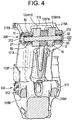
FIG. 4 is a cross sectional view of a portion of the hitch ofFIG. 2 taken across line 4-4; -
FIG. 5 is a perspective view of a journal bearing of the present invention; -
FIG. 6 is an inside perspective view of an end cap of the H-Link ofFIG. 3 ; -
FIG. 7 . is a cross sectional view of the journal bearing assembly ofFIG. 2 shown with the journal bearing ofFIG. 5 therein; -
FIG. 8 is a cross sectional view of a thrust bearing of the present invention installed in a journal bearing assembly; -
FIG. 9 is a perspective and enlarged view of a cup portion of the journal bearing assembly ofFIG. 8 shown with the thrust bearing therein; -
FIG. 10 is a cross sectional view of a first embodiment of a thrust bearing of the present invention; -
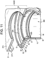
FIG. 11 an exploded perspective view of the thrust bearing ofFIG. 10 ; -
FIG. 12 is a top view of the thrust pad of the thrust bearing ofFIG. 10 ; -
FIG. 13 is a cross sectional view of a second embodiment of a thrust bearing of the present invention; -
FIG. 14 is an exploded and cross sectional view of the thrust bearing ofFIG. 13 ; -
FIG. 15 is a cross sectional view of a third embodiment of a thrust bearing of the present invention; -
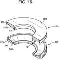
FIG. 16 is an exploded and cross sectional view of the thrust bearing ofFIG. 15 ; -
FIG. 17 is a cross sectional view of a fourth embodiment of a thrust bearing of the present invention; -
FIG. 18 is a top perspective view of the thrust plate of the thrust bearing ofFIG. 17 ; -
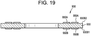
FIG. 19 is a cross sectional view of the thrust plate ofFIG. 18 taken across line 19-19; -
FIG. 20 is a cross sectional view of on an embodiment of a journal bearing with spiral grooves formed therein; -
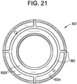
FIG. 21 is a bottom view of an embodiment of any of the thrust bearings ofFIGS. 8 ,10 ,13 ,15 and17 ; -
FIG. 22 is a cross sectional view of a portion of the journal bearing ofFIGS. 5 and7 illustrating one embodiment of a seal of the present invention; -
FIG. 23 is a cross sectional view of a portion of the journal bearing ofFIG. 3 illustrating one embodiment of a seal of the present invention; -
FIG. 24 is a cross sectional view of a portion of any of the journal bearings ofFIGS. 3 ,5 and7 illustrating another embodiment of a seal of the present invention; -
FIG. 25 is a cross sectional view another embodiment of the bearing and seal ofFIG. 22 in which the bearing has radial and axial slots formed therein; -
FIG. 26 is an end view of the bearing and seal ofFIG. 25 taken from the viewpoint of line 26-26; and -
FIG. 27 is a schematic cross sectional view of a self-lubricating pad and sleeve of the present invention. - Referring to
FIG. 2 , a bearing system for a hitch assembly for a heavy load capacity vehicle (e.g., ascraper bowl 102 hitched (via the hitch assembly 103) to and pulled by a diesel engine power cabin orcab 100, as shown inFIG. 1 ) is generally designated by thenumber 1000. Thebearing system 1000 includes a linkage structure having three links, for example: 1) acabin support link 101A (e.g., a support structure) extending from thecabin 101; 2) abowl support link 102A (e.g., a support structure); and 3) aconnector link 103A (e.g., a support structure) that moveably couples thecabin support link 101A to thebowl support link 102A to allow rotational movement in two or more axes of rotation (e.g., horizontal and vertical). In one embodiment, apiston cylinder assembly 103P is coupled to thecabin support link 101A and theconnector link 103A. - As shown in
FIG. 2 the bearing system includes: 1) a firstjournal bearing assembly 200 that is moveably secured to thecabin support link 101A and theconnector link 103A; 2) a secondjournal bearing assembly 300 is moveably secured to thecabin support link 101A and theconnector link 103A; 3) a thirdjournal bearing assembly 400 moveably secured to theconnector link 103A and thebowl support link 102A; 4) a fourthjournal bearing assembly 500 moveably secured to theconnector link 103A and thebowl support link 102A; and 5) athrust bearing assembly 600 disposed above the fourthjournal bearing assembly 500 and between theconnector link 103A and thebowl support link 102A. In one embodiment, one or more seals, as described herein, are disposed in one or more of the firstjournal bearing assembly 200, the secondjournal bearing assembly 300, the thirdjournal bearing assembly 400, the fourthjournal bearing assembly 500 and thethrust bearing assembly 600. - As shown in
FIG. 2 the first journal bearing assembly is generally designated by thenumber 200. The first journal bearing assembly 200 (e.g., an H-link assembly as shown inFIG. 3 ) includes four self-lubricating sleeve assemblies 10 (seeFIG. 5 ) disposed therein and an end cap (212, 12 inFIG. 6 ) positioned on an axial end of each of four positions on the firstjournal bearing assembly 200. The thrust bearingend caps 212 each have a self-lubricating pad 8 (SeeFIG. 6 ) disposed on an axially inward facing surface thereof. While the thrust bearing end caps are shown and described herein, the present invention is not limited in this regard, as other configurations may apply, including, but not limited to, those with integrally sealed or welded ends, or with no end caps or partial end caps. - As shown in
FIGS. 3 ,4 ,5 ,7 ,8 ,10 .11 ,13 ,15 ,17 ,20 ,22 ,23 and25 , each of the self-lubricatingsleeve assemblies 10 includes anouter sleeve 50 with a self-lubricatingsleeve 58 secured (e.g., via an adhesive such as epoxy or phenolic resin) to an interior surface of theouter sleeve 50, as described further herein. - As shown in
FIG. 2 the second journal bearing assembly is generally designated by thenumber 300. The second journal bearing assembly 300 (e.g., an H-link assembly as shown inFIG. 3 ) includes four of the self-lubricating sleeve assemblies 10 (seeFIG. 5 ) disposed therein and one of the end caps (312, 12 inFIG. 6 ) positioned on an axial end of each of four positions on the secondjournal bearing assembly 300. Theend caps 312 each have one of the self-lubricating pads 8 (seeFIG. 6 ) disposed on the axially inward facing surface thereof. - The third
journal bearing assembly 400 includes one of the self-lubricating sleeve assemblies 10 (seeFIG. 5 ) disposed therein. - The fourth
journal bearing assembly 500 includes one of the self-lubricating sleeve assemblies 10 (seeFIG. 5 ) disposed therein. Thethrust bearing assembly 600 is disposed around the fourthjournal bearing assembly 500 and includes a self-lubricating cartridge 14 (seeFIG. 10 ) disposed on at least one axially facing surface thereof. - As shown in
FIG. 3 , the firstjournal bearing assembly 200 is mounted in a first housing 216 (e.g., a body portion of the H-link). Thefirst housing 216 includes afirst leg 218A and asecond leg 218B spaced apart from and centrally coupled to one another by a joint 219. - As shown in
FIG. 3 , a first bore 220 extends through thefirst leg 218A and thesecond leg 218B. One of the self-lubricating sleeve assemblies 10 (seeFIG. 5 ) is secured in the first bore 220 of each of thefirst leg 218A and thesecond leg 218B. A first shaft 222 extends into and rotatingly engages a radially inward facing surface of each of the self-lubricatingsleeves 58 in the first bore 220 of each of thefirst leg 218A and thesecond leg 218B. The first shaft 222 is configured to receive a first hub 101H1 (as shown inFIG. 2 ) therearound and between thefirst leg 218A and thesecond leg 218B. The first hub 101H1 extends from thecabin support link 101A. A thrust bearingend cap 212 is removably secured (e.g., via bolting) to an axially outward facingsurface 200F of each thefirst housing 216 outside of the first bore 220 of the each of thefirst leg 218A and thesecond leg 218B. As shown inFIG. 6 , each of the end caps 212 incudes a self-lubricatingpad 8 secured thereto for sliding engagement with a respective axial end of the first shaft 222. The self-lubricatingpad 8 is centrally located between a circular pattern ofbolt holes 8H, as shown inFIG. 6 . - As shown in
FIG. 3 , a second bore 221 extends through the first leg 212A and the second leg 212B. One of the self-lubricating sleeve assemblies 10 (seeFIG. 5 ) is secured in the second bore 221 of each of thefirst leg 218A and thesecond leg 218B. Asecond shaft 223 extends into and rotatingly engages an axially inward facing surface of each of the self-lubricating pads 8 in the first bore 220 of each of thefirst leg 218A and thesecond leg 218B. Thesecond shaft 223 is configured to receive a pair of second hubs 103H1A and 103H1B therearound (as shown inFIG. 2 ) and between thefirst leg 218A and thesecond leg 218B. The pair of second hubs 103H1A and 103H1B extend from theconnector link 103A. A thrust bearingend cap 212 is removably secured (e.g., via bolting) to an axially outward facingsurface 200F of each thefirst housing 216 outside of the second bore 221 of the each of thefirst leg 218A and thesecond leg 218B. As shown inFIG. 6 , each of the end caps 212 incudes a self-lubricatingpad 8 secured thereto for sliding engagement with a respectiveaxial end 223E of thefirst shaft 223, as shown inFIG. 3 . The self-lubricatingpad 8 is centrally located between a circular pattern ofbolt holes 8H. In one embodiment, a piston hub 103PA extends from thepiston cylinder assembly 103P and has a bore therein in which theshaft 223 extends. The piston hub 103PA is positioned between the pair of second hubs 103H1A and 103H1B, as shown inFIG 4 . - As shown in
FIG. 3 , the secondjournal bearing assembly 300 is mounted in a second housing 316 (e.g., a body portion of the H-link). Thesecond housing 316 includes afirst leg 318A and asecond leg 318B spaced apart from and centrally coupled to one another by a joint 319. - As shown in
FIG. 3 , a third bore 320 extends through thefirst leg 318A and thesecond leg 318B. One of the self-lubricating sleeves 10 (seeFIG. 5 ) is secured in the third bore 320 of each of thefirst leg 318A and thesecond leg 318B. A third shaft 322 extends into and rotatingly engages a radially inward facing surface of each of the self-lubricatingsleeves 58 in the third bore 320 of each of thefirst leg 318A and thesecond leg 318B. The third shaft 322 is configured to receive a third hub 101H2 therearound and between thefirst leg 318A and thesecond leg 318B. The third hub 101H2 extends from thecabin support link 101A. A thrust bearingend cap 312 is removably secured (e.g., via bolting) to an axially outward facingsurface 300F of thesecond housing 316 outside of the third bore 320 of the each of thefirst leg 318A and thesecond leg 318B. As shown inFIG. 6 , each of the end caps 312 incudes a self-lubricatingpad 8 secured thereto for sliding engagement with a respective axial end 322E of the third shaft 322. The self-lubricatingpad 8 is centrally located between a circular pattern ofbolt holes 8H. - As shown in
FIG. 3 , a second bore 321 extends through thefirst leg 318A and thesecond leg 318B. One of the self-lubricating sleeves 10 (seeFIG. 5 ) is secured in the second bore 321 of each of thefirst leg 318A and thesecond leg 318B. A fourth shaft 323 extends into and rotatingly engages a radially inward facing surface of each of the self-lubricatingsleeves 58 in the first bore 320 of each of thefirst leg 318A and thesecond leg 318B. The fourth shaft 323 is configured to receive a fourth hub 103H2 therearound and between thefirst leg 318A and thesecond leg 318B. The fourth hub 103H2 extends from theconnector link 103A. A thrust bearingend cap 312 is removably secured (e.g., via bolting) to an axially outward facingsurface 300F of each thesecond housing 316 outside of the fourth bore 321 of the each of thefirst leg 318A and thesecond leg 318B. As shown inFIG. 6 , each of the end caps 312 incudes a self-lubricatingpad 8 secured thereto for sliding engagement with a respective axial end 322E of the fourth shaft 323. The self-lubricatingpad 8 is centrally located between a circular pattern ofbolt holes 8H. - As shown in
FIG. 3 , a third journal bearing assembly 400 (e.g., a vertical journal bearing assembly) is mounted in a third housing 102H1. The third housing 102H1 extends from thebowl support link 102A and is positioned between a fifth leg 103L5 and a sixth leg 103L6 each extending from theconnector link 103A. As shown inFIG. 7 , afifth bore 425 extends through the third housing 102H1, the fifth leg 103L5 and the sixth leg 103L6. One of the self-lubricatingsleeves 8 is secured in thefifth bore 425. Afifth shaft 435 extends into and rotatingly engages a radially inward facing surface of the self-lubricatingsleeve 58. - As shown in
FIG. 3 , a fourth journal bearing assembly 500 (e.g., a vertical journal bearing assembly) is mounted in a fourth housing 103H3. The fourth housing 103H3 extends from theconnector link 103A and is positioned between a seventh leg 102L7 and an eighth leg 102L8 each extending from thebowl support link 102A. As shown inFIG. 10 , asixth bore 526 extends through the fourth housing 103H3, the seventh leg 102L7 and the eighth leg 102L8. One of the self-lubricatingsleeve assemblies 10 is secured in thefifth bore 435. Asixth shaft 536 extends into and rotatingly engages a radially inward facing surface of the self-lubricatingsleeve 8. The fourth housing 103H3 has anannular recess 529 formed therein. - As shown in
FIG. 10 , a thrust bearing cartridge 14 is positioned in theannular recess 529, between the seventh leg 102L7 and the fourth housing 103H3. The thrust bearing cartridge 14 includes one or more self-lubricating pads 30 therein. The thrust bearing cartridge 14 is positioned above and spaced apart from the fourthjournal bearing assembly 500 by a distance D20. - As shown in
FIG. 10 , the thrust bearing cartridge 14 includes afirst thrust plate 31 having a first axially outwardly facingsurface 31A and a first axially inwardly facingsurface 31B. The thrust bearing cartridge 14 includes asecond thrust plate 32 having a second axially outwardly facing 32A surface and a second axially inwardly facingsurface 32B. The first axially inwardly facingsurface 31B and the second axially inwardly facingsurface 32B arranged to face one another. A self-lubricating pad 30 (e.g., liner or annular pads) is secured to the second axially inwardly facingsurface 32B, wherein a portion of the self-lubricating liner slidingly engages the first axially inwardly facingsurface 31B. - As shown in
FIG. 10 , the thrust bearing cartridge 14 includes anannular flange 31F extending from a first radially outer portion of thefirst thrust plate 31 and over a second outer portion of thesecond thrust plate 32. In one embodiment, a bearing seal 35 (e.g., an annular lip seal) extends between theannular flange 31F and thesecond thrust plate 32. Theseal 35 is moveable with respect to thefirst thrust plate 31 and/or thesecond thrust plate 32. In one embodiment, anotherannular seal 39 extends between and sealingly engages radially inward portions of thefirst thrust plate 31 and/or thesecond thrust plate 32. - In one embodiment, the first
axially facing surface 31B has a surface roughness of Ra 16 toRa 8. - In one embodiment, the
first thrust plate 31 has a firstcentral opening 31X extending therethrough and thesecond thrust plate 32 has a secondcentral opening 32X extending therethrough. - In one embodiment, an
annular shaft seal 36 is disposed in the firstcentral opening 31X and/or the secondcentral opening 32X and engages thesixth shaft 536. In one embodiment, one annular shaft seal 36 (e.g., bearing seal) is disposed on radially inner portions of thefirst thrust plate 31 and/or thesecond thrust plate 32. - In one embodiment, the self-lubricating
pad 30 has one or more grooves G (e.g., three grooves shown) formed therein for collection of debris. - As shown in
FIGS. 13 and14 , the thrust bearing cartridge 714 is similar to the thrust bearing cartridge 14 ofFIG. 10 . Thus, similar elements are assigned similar reference characters preceded by the numeral 7. Thefirst thrust plate 731 has a decreasing taper (e.g., angle □ in a radially outward direction) and thesecond thrust plate 732 has in increasing taper in the radially outward direction. A self-lubricatingliner 730 is disposed between thefirst thrust plate 731 and thesecond thrust plate 732, similar to that described above for the thrust bearing cartridge 14. The thrust bearing cartridge 714 has a C-shapedannular seal 735 extending between and slidingly engaging thefirst thrust plate 731 and thesecond thrust plate 732, on radially outward portions thereof. The thrust bearing cartridge 714 has a C-shapedannular seal 739 extending between and slidingly engaging thefirst thrust plate 731 and thesecond thrust plate 732, on a radially inward portion thereof. - As shown in
FIG. 13 , the C-shapedannular seal 735 includes afirst leg 735A extending radially inward from one end of abase portion 735B and asecond leg 735C extending radially inward from a second end of thebase portion 735B. In one embodiment, a J-shapedcup 735J is secured over thesecond leg 735C. The J-shaped cup is manufactured from a lubricious material such as a plastic. The J-shapedcup 735J is seated in and slidingly engages a second groove 732G1 formed in thesecond thrust plate 732. Thefirst leg 735A is secured in a first groove 731G1 formed in thefirst thrust plate 731. While the J-shaped cup is shown and described as being secured over thesecond leg 735C, the present invention is not limited in this regard as one of the J-shaped cups may be secured to thefirst leg 735A in addition to or in the alternative to being secured to thesecond leg 735C. - As shown in
FIG. 13 , the C-shapedannular seal 739 includes afirst leg 739A extending radially outward from one end of abase portion 739B and asecond leg 739C extending radially outward from a second end of thebase portion 739B. In one embodiment, a J-shapedcup 739J is secured over thesecond leg 739C. The J-shaped cup is manufactured from a lubricious material such as a plastic. The J-shapedcup 739J is seated in and slidingly engages a second groove 732G2 formed in thesecond thrust plate 732. Thefirst leg 739A is secured in a first groove 731G2 formed in thefirst thrust plate 731. While the J-shaped cup is shown and described as being secured over thesecond leg 739C, the present invention is not limited in this regard as one of the J-shaped cups may be secured to thefirst leg 739A in addition to or in the alternative to being secured to thesecond leg 739C. - As shown in
FIGS. 8 ,15 and16 , thethrust bearing cartridge 814 is similar to the thrust bearing cartridge 714 ofFIGS. 13 and14 . Thus, similar elements are assigned similar reference characters with the leading numeral 7 replaced with thenumeral 8. The first inwardly facingsurface 831B has an arcuate contour, for example a spherical contour. - As shown in
FIGS. 17 ,18 and19 , the thrust bearing cartridge 914 is similar to the thrust bearing cartridge 14 ofFIGS. 10 . Thus, similar elements are assigned similar reference characters preceded by thenumeral 9. The thrust bearing cartridge 914 includes afirst thrust plate 931 having a first axially outwardly facingsurface 931A and a first axially inwardly facingsurface 931B. The thrust bearing cartridge 914 includes asecond thrust plate 932 having a second axially outwardly facingsurface 931A and a second axially inwardly facingsurface 932B. The first axially inwardly facingsurface 931B and the second axially inwardly facingsurface 932B arranged to face one another. The thrust bearing cartridge 914 includes athird thrust plate 930 having two third axially outward facing surfaces 930B1 and 930B2. Thethird thrust plate 930 is positioned between thefirst thrust plate 931 and thesecond thrust plate 932. A self-lubricatingliner 950A is secured to the third axially outwardly facing surface 930B2 and a self-lubricatingliner 950B is secured to the third axially outwardly facing surface 930B1. A portion of the self-lubricatingliner 950B slidingly engages the first axially inwardly facingsurface 931B and a portion of the self-lubricatingliner 950A slidingly engages the second axially inward facingsurface 932B. In one embodiment the thrust bearing cartridge 914 includes a C-shapedcover 940 that has a radiallyoutward flange 940F and a radiallyinward flange 940E that extend axially over thefirst thrust plate 931,second thrust plate 932 and thethird thrust plate 930. The C-shapedcover 940 covers the first axiallyoutward surface 931A. The C-shapedcover 940 has a radially inward facinglip 940Y swaged over a radially outer portion of the second axially outward facingsurface 932A. The C-shapedcover 940 has a radially outward facinglip 940X swaged over a radially inner portion of the second axially outward facingsurface 932A. - Referring to
FIG. 21 , in one embodiment thesecond thrust plate grooves 862 formed in the second axially outward facingsurface 832A. Thegrooves 862 provide a flow path for liquids such as water to flow through and discharge through a channel 861 (seeFIG. 8 ) formed in the fourth hub 103H2. - As shown in
FIGS. 25 and26 , for thejournal bearing assemblies shaft axial slots 88A extending axially along theexterior surface 50E of theouter sleeve 50. Theaxial slots 88A transition into aradial slot 88R at thefirst end 50A of theouter sleeve 50 Theaxial slots 88A have a depth sufficient to allow water to flow down and out of theouter sleeve 50 as indicated by the arrows Q, in order to prevent water collection above theannular seal 37. Theradial slots 88R extend an axial distance D10 from thefirst end 50A (i.e., top end) to a plane aligned with atop edge 37E of theannular seal 37. Theradial slots 88R extend radially through (i.e., entirely) theouter sleeve 50 along the axial length D10. - As shown in
FIG. 27 , the self-lubricating pads sleeve 58 are manufactured from a self-lubricating material and liners, such as but not limited to polytetrafluoroethylene (PTFE) materials and liner systems with resins including, phenolic resins, polyimide resins and polyimide resins in conjunction with fiber weaves, fabrics or matrix materials, including but not limited to polyester, meta-aramids (e.g., NOMEX), PTFE and glass. In one embodiment, the self-lubricating material and liners are a homogeneous entity or are a molded nearly homogenous system without a weave, fabric or matrix and are manufactured from one or more acrylates, as described further herein with respect toFIG. 27 . In one embodiment, the self-lubricating material and liners are ceramic materials and metals. In one embodiment, the self-lubricating material is disposed on a metal substrate as described herein such as theend cap FIG. 6 and theouter sleeve 50 ofFIG. 7 . The self-lubricating material has properties and characteristics sufficient to withstand high loads with insignificant wear. The use of the self-lubricating material in the manufacture of the self-lubricating pads sleeve 58 allows lubricious properties of the self-lubricating material to be maintained without addition of a lubricating agent such as oil or grease. - In one embodiment, as shown, for example, in
FIG. 10 , the self-lubricatingpad sleeve 58 are manufactured from a self-lubricating woven fabric 73. The woven fabric 73 includes a plurality offibers 73B interwoven with one another and polytetrafluoroethylene (PTFE) 73A interwoven therewith. Thefibers 73B include, for example, a polyester material, a stainless steel material and/or glass material. Thefibers 73B interwoven with the PTFE enhance bondability of the self-lubricatingpad sleeve 58 to a substrate. In one embodiment, the interface (e.g., theshaft sleeve 58 the liner or opposing (e.g., axial end theshaft surface 31B) the self-lubricating pads - As shown in
FIGS. 3 ,4 ,5 ,7 ,8 ,22 ,23 and25 , the self-lubricatingjournal bearing assemblies sleeve assemblies 10 therein and each of the self-lubricatingjournal bearing assemblies sleeve assemblies 10 therein. Each of the self-lubricatingsleeve assemblies 10 includes an outer sleeve 50 (e.g., a metallic sleeve) extending from a firstaxial end 50A to a secondaxial end 50B thereof (FIGS. 5 &7 ). As shown inFIG. 7 , theouter sleeve 50 has anexterior surface 50E and aninterior surface 50F. Theinterior surface 50F has afirst recess 51A formed therein. Thefirst recess 51A extends axially inward from the firstaxial end 50A and radially outward from theinterior surface 50F. Theinterior surface 50F has asecond recess 51B formed therein. Thesecond recess 51B extends axially inward from the secondaxial end 50B and radially outward from theinterior surface 50F. A self-lubricatingsleeve 58 is secured (e.g., adhered to via an adhesive such as an epoxy or phenolic resin) to theinterior surface 50F between thefirst recess 51A and thesecond recess 51B. In one embodiment, a firstannular seal 37 is disposed in thefirst recess 51A and a secondannular seal 37 disposed in thesecond recess 51B. In one embodiment, the self-lubricatingsleeve 58 comprises PTFE as described further herein with respect toFIG 27 . It is contemplated that more than one first annular seal can be disposed in the first recess and more than one second annular seal can be disposed in the second recess. - As shown in
FIGS. 3 , the self-lubricatingsleeve 58 comprises at least one groove G therein. As shown inFIG. 20 , in one embodiment, the grooves G have a spiral configuration. In another embodiment, the grooves have a circumferential configuration. In one embodiment, the least one groove G extends into theouter sleeve 50. - As shown in
FIGS. 22 and23 , theannular seal 37 includes abase portion 37B with a first leg 37L1 and a second leg 37L2 extending outward therefrom at an angle Z relative to an interior surface of therecess 51A. In one embodiment, theannular seal 37 has an L-shapedmetallic retainer 37R embedded in thebase 37B. The base 37B of theannular seal 37 is biased radially outward to frictionally secure theannular seal 37 into therecess 51A. The first leg 37L1 and the second leg 37L2 are flexible and urged radially outward from a relaxed state (shown by dashed lines) by contact with theshaft - As shown in
FIG. 24 , the seal 37' includes abase portion 37B' with a first leg 37L1' and a second leg 37L2' extending outward therefrom. The annular seal 37' has a C-shapedmetallic retainer 37R' secured to thebase 37B and axially enveloping the annular seal 37'. The C-shapedretainer 37R' is press fit into therecess 51A to secure the annular seal 37' therein. - Although the invention is described with reference to particular embodiments thereof, it will be understood by one of ordinary skill in the art, upon a reading and understanding of the foregoing disclosure that numerous variations and alterations to the disclosed embodiments will fall within the scope of this invention and of the appended claims.
- Aspects of the invention are embodied in the following propositions, which may be taken alone or in combination with each other:
- Proposition 1: A bearing system for a hitch assembly for a heavy load capacity vehicle, the bearing system comprising:
- a linkage structure having at least three links;
- at least one self-lubricating sleeve;
- at least one thrust bearing end cap;
- a first journal bearing assembly comprising at least one of the at least one self-lubricating sleeves disposed therein and at least one of the at least one thrust bearing end caps positioned on an axial end of the first journal bearing assembly, the at least one thrust bearing end cap having a first self-lubricating pad disposed on an axially inward facing surface thereof, the first journal bearing assembly being moveably secured to at least two of the at least three links;
- a second journal bearing assembly comprising at least one of the at least one self-lubricating sleeves disposed therein and the at least one of the at least one thrust bearing end caps positioned on an axial end of the second journal bearing assembly, the at least one thrust bearing end cap having a second self-lubricating pad disposed on the axially inward facing surface thereof, the second journal bearing assembly being moveably secured to at least two of the at least three links;
- a third journal bearing assembly comprising the at least one of the at least one self-lubricating sleeves disposed therein, the third journal bearing being moveably secured to at least two of the at least three links;
- a fourth journal bearing assembly comprising the at least one of the at least one self-lubricating sleeves disposed therein, the fourth journal bearing being moveably secured to at least two of the at least three links; and
- a thrust bearing assembly disposed between two of the at least three links, the thrust bearing assembly comprising a third self-lubricating pad disposed on at least one axially facing surface thereof.
- Proposition 2: A bearing system for a hitch assembly for a heavy load capacity vehicle, the bearing system comprising:
- (a) a first journal bearing assembly mounted in a first housing, the first housing comprising a first leg and a second leg spaced apart from and centrally coupled to one another, each of the first leg and the second leg comprising:
- a first bore extending through the first leg and the second leg, the first journal bearing assembly comprising:
- a first self-lubricating sleeve secured in the first bore of each of the first leg and the second leg;
- a first shaft extending into and rotatingly engaging a radially inward facing surface of the first self-lubricating sleeve, the first shaft being configured to receive a first hub therearound and between the first leg and the second leg, the first hub extending from a first support structure;
- a first thrust bearing end cap removably secured to an axially outward facing surface of each of the first bores of the first leg and the second leg, each of the end caps comprising a first self-lubricating pad secured thereto for sliding engagement with a respective axial end of the first shaft;
- a second bore extending through the first leg and the second leg, the first journal bearing assembly comprising:
- a second self-lubricating sleeve secured in the second bore of each of the first leg and the second leg;
- a second shaft extending into and rotatingly engaging a radially inward facing surface of the second self-lubricating sleeve, the second shaft being configured to receive at least one second hub therearound and between the first leg and the second leg, the at least one second hub extending from a link structure;
- a second thrust bearing end cap removably secured to an axially outward facing surface of each of the second bores of the first leg and the second leg, each of the second end caps comprising a second self-lubricating pad secured thereto for sliding engagement with a respective axial end of the second shaft;
- a first bore extending through the first leg and the second leg, the first journal bearing assembly comprising:
- (b) a second journal bearing assembly mounted in a second housing, the second housing comprising a third leg and a fourth leg spaced apart from and centrally coupled to one another, each of the third leg and the fourth leg comprising:
- a third bore extending through the third leg and the fourth leg, the second journal bearing assembly comprising:
- a third self-lubricating sleeve secured in the third bore of each of the third leg and the fourth leg;
- a third shaft extending into and rotatingly engaging a radially inward facing surface of the third self-lubricating sleeve, the third shaft being configured to receive a third hub therearound and between the third leg and the fourth leg, the third hub being extending from the first support structure;
- a third thrust bearing end cap removably secured to an axially outward facing surface of each of the third bores of the third leg and the fourth leg, each of the third end caps comprising a third self-lubricating pad secured thereto for sliding engagement with a respective axial end of the third shaft;
- a fourth bore extending through the third leg and the fourth leg, the second journal bearing assembly comprising:
- a fourth self-lubricating sleeve secured the fourth bore of each of the third leg and the fourth leg;
- a fourth shaft extending into and rotatingly engaging a radially inward facing surface of the fourth self-lubricating sleeve, the fourth shaft being configured to receive a fourth hub therearound and between the third leg and the fourth leg, the fourth hub extending from the link structure;
- a fourth thrust bearing end cap removably secured to an axially outward facing surface of each of the fourth bores of the third leg and the fourth, each of the fourth end caps comprising a fourth self-lubricating pad secured thereto for sliding engagement with a respective axial end of the fourth shaft;
- a third bore extending through the third leg and the fourth leg, the second journal bearing assembly comprising:
- (c) a third journal bearing assembly mounted in a third housing, the third housing extending from a second support structure and being positioned between a fifth leg and a sixth leg each extending from the link structure; the third journal bearing comprising:
a fifth bore extending through the third housing, the fifth leg and the sixth leg, the third journal bearing assembly comprising:- a fifth self-lubricating sleeve secured in the fifth bore;
- a fifth shaft extending into and rotatingly engaging a radially inward facing surface of the fifth self-lubricating sleeve;
- (d) a fourth journal bearing assembly mounted in a fourth housing, the fourth housing extending from the link structure and being positioned between a fifth hub and a sixth hub each extending from the second support structure, the fourth journal bearing comprising:
a sixth bore extending through the fourth housing, the fifth hub and the sixth hub,:- a sixth self-lubricating sleeve secured in the fifth bore;
- a sixth shaft extending into and rotatingly engaging a radially inward facing surface of the sixth self-lubricating sleeve; and
- (e) a thrust bearing positioned between the fifth hub and the fourth housing, the thrust bearing comprising at least one fifth self-lubricating pad.
- (a) a first journal bearing assembly mounted in a first housing, the first housing comprising a first leg and a second leg spaced apart from and centrally coupled to one another, each of the first leg and the second leg comprising:
- Proposition 3: A thrust bearing comprising:
- a first thrust plate having a first axially outwardly facing surface and a first axially inwardly facing surface;
- a second thrust plate having a second axially outwardly facing surface and a second axially inwardly facing surface;
- the first axially inwardly facing surface and the second axially inwardly facing surface arranged to face one another; and
- a self-lubricating liner being secured to the second axially inwardly facing surface, wherein a portion of the self-lubricating liner slidingly engages the first axially inwardly facing surface.
- Proposition 4: The thrust bearing of proposition 3, further comprising at least one bearing seal extending between the first thrust plate and the second thrust plate, wherein the seal is moveable with respect to at least one of the first thrust plate and the second thrust plate.
- Proposition 5: The thrust bearing of proposition 3, wherein the first axially facing surface has a surface roughness of Ra 16 to
Ra 8. - Proposition 6: The thrust bearing of proposition 3, wherein the first thrust plate comprises a first central opening extending therethrough and the second thrust plate comprises a second central opening extending therethrough.
- Proposition 7: The thrust bearing of proposition 6, further comprising an annular shaft seal disposed in at least one of the first central opening and the second central opening.
- Proposition 8: The thrust bearing of proposition 3, wherein the first thrust plate comprises an annular flange extending from a first radially outer portion of the first thrust plate and over a second outer portion of the second thrust plate.
- Proposition 9: The thrust bearing of
proposition 4, wherein the first thrust plate comprises an annular flange extending from a first radially outer portion of the first thrust plate and over a second outer portion of the second thrust plate and wherein one of the at least one bearing seals extends between the annular flange and the second thrust plate. - Proposition 10: The thrust bearing of
proposition 4, wherein one of the at least one bearing seals is disposed on radially inner portions of the first thrust plate and the second thrust plate. - Proposition 11: The thrust bearing of proposition 3, wherein the self-lubricating liner comprises at least one groove formed therein for collection of debris.
- Proposition 12: The thrust bearing of proposition 3, wherein the first thrust plate has a decreasing taper in a radially outward direction and the second thrust plate has in increasing taper in the radially outward direction.
- Proposition 13: The thrust bearing of proposition 3, wherein the first inwardly facing surface has an arcuate contour.
- Proposition 14: The thrust bearing of
proposition 4, wherein the at least one bearing seal has a C-shaped cross having two legs extending therefrom and wherein at least one of the legs has a lubricious cup secured thereto. - Proposition 15: A thrust bearing comprising:
- a first thrust plate having a first axially outwardly facing surface and a first axially inwardly facing surface;
- a second thrust plate having a second axially outwardly facing surface and a second axially inwardly facing surface;
- the first axially inwardly facing surface and the second axially inwardly facing surface arranged to face one another; and
- a third thrust plate having two third axially outward facing surfaces, the third thrust plate being positioned between the first thrust plate and the second thrust plate, a self-lubricating liner being secured to each of two third axially outwardly facing surfaces, wherein a portion of the self-lubricating liner slidingly engages the first axially inwardly facing surface and the second axially inward facing surfaces.
- Proposition 16: The thrust bearing of proposition 15, further comprising a C-shaped cover extending over the first thrust plate, the second thrust plate and the third thrust plate.
- Proposition 17: The thrust bearing of proposition 3 or 15, wherein the second axially inwardly facing surface has a plurality of drainage grooves formed therein.
- Proposition 18: The thrust bearing of proposition 17, wherein the drainage grooves communicate with a drainage line formed in a housing in which the thrust bearing seats.
- Proposition 19: A self-lubricating journal bearing assembly comprising:
- an outer sleeve extending from a first axial end to a second axial end thereof, the outer sleeve having an exterior surface and an interior surface, the interior surface having a first recess formed therein, the first recess extending axially inward from the first axial end and radially outward from the interior surface, the interior surface having a second recess formed therein, the second recess extending axially inward from the second axial end and radially outward from the interior surface; and
- a self-lubricating sleeve being secured to the interior surface between the first recess and the second recess.
- Proposition 20: The self-lubricating journal bearing assembly of
proposition 19, further comprising at least one of a first annular seal disposed in the first recess and at least one of a second annular seal disposed in the second recess. - Proposition 21: The self-lubricating journal bearing assembly of
proposition 19, wherein the self-lubricating sleeve comprises PTFE. - Proposition 22: The self-lubricating journal bearing assembly of
proposition 19, wherein the self-lubricating sleeve comprises at least one groove therein. - Proposition 23: The self-lubricating journal bearing assembly of proposition 22, wherein the at least one groove has a spiral configuration.
- Proposition 24: The self-lubricating journal bearing assembly of proposition 22, wherein the at least one groove has a circumferential configuration.
- Proposition 25: The self-lubricating journal bearing assembly of proposition 22, wherein the at least one groove extends into the outer sleeve.
- Proposition 26: The self-lubricating journal bearing assembly of
proposition 19, wherein the outer sleeve comprises a metallic material. - Proposition 27: The self-lubricating journal bearing assembly of
proposition 19, further comprising at least one axial groove formed on the exterior surface of the outer sleeve and at least one radial groove extending radially through the outer sleeve, the at least one radial groove extending axially inward from the first axial end of the outer sleeve. - Proposition 28: The self-lubricating journal bearing assembly of proposition 27, further comprising at least one of a first annular seal disposed in the first recess and at least one of a second annular seal disposed in the second recess.
- Proposition 29: The self-lubricating journal bearing assembly of proposition 28, wherein each of the at least one of the first annular seal and the at least one of the second annular seal comprises a base portion with a first leg and a second leg extending outwardly therefrom at an angle relative to the respective one of the first recess and the second recess.
- Proposition 30: The self-lubricating journal bearing assembly of proposition 29, wherein the at least one of the first annular seal and the at least one of the second annular seal each have an L-shaped metallic retainer embedded in the base portion.
- Proposition 31: The self-lubricating journal bearing assembly of proposition 29, wherein the base portion of the annular seal is biased radially outward to frictionally secure the at least one of the first annular seal into the first recess and the at least one of the second annular seal into the second recess.
- Proposition 32: A bearing system for a hitch assembly for a heavy load capacity vehicle, the bearing system comprising:
- a linkage structure having at least three links;
- at least one self-lubricating sleeve;
- a first journal bearing assembly comprising at least one of the at least one self-lubricating sleeves disposed therein positioned on an axial end of the first journal bearing assembly, the first journal bearing assembly being moveably secured to at least two of the at least three links;
- a second journal bearing assembly comprising at least one of the at least one self-lubricating sleeves disposed therein, the second journal bearing assembly being moveably secured to at least two of the at least three links;
- a third journal bearing assembly comprising the at least one of the at least one self-lubricating sleeves disposed therein, the third journal bearing being moveably secured to at least two of the at least three links;
- a fourth journal bearing assembly comprising the at least one of the at least one self-lubricating sleeves disposed therein, the fourth journal bearing being moveably secured to at least two of the at least three links; and
a thrust bearing assembly disposed between two of the at least three links, the thrust bearing assembly comprising a third self-lubricating pad disposed on at least one axially facing surface thereof.
Claims (15)
- A bearing system for a hitch assembly for a heavy load capacity vehicle, the bearing system comprising:a linkage structure having at least three links;at least one self-lubricating sleeve;at least one thrust bearing end cap;a first journal bearing assembly comprising at least one of the at least one self-lubricating sleeves disposed therein and at least one of the at least one thrust bearing end caps positioned on an axial end of the first journal bearing assembly, the at least one thrust bearing end cap having a first self-lubricating pad disposed on an axially inward facing surface thereof, the first journal bearing assembly being moveably secured to at least two of the at least three links;a second journal bearing assembly comprising at least one of the at least one self-lubricating sleeves disposed therein and the at least one of the at least one thrust bearing end caps positioned on an axial end of the second journal bearing assembly, the at least one thrust bearing end cap having a second self-lubricating pad disposed on the axially inward facing surface thereof, the second journal bearing assembly being moveably secured to at least two of the at least three links;a third journal bearing assembly comprising the at least one of the at least one self-lubricating sleeves disposed therein, the third journal bearing being moveably secured to at least two of the at least three links;a fourth journal bearing assembly comprising the at least one of the at least one self-lubricating sleeves disposed therein, the fourth journal bearing being moveably secured to at least two of the at least three links; anda thrust bearing assembly disposed between two of the at least three links, the thrust bearing assembly comprising a third self-lubricating pad disposed on at least one axially facing surface thereof.
- A bearing system for a hitch assembly for a heavy load capacity vehicle, the bearing system comprising:(a) a first journal bearing assembly mounted in a first housing, the first housing comprising a first leg and a second leg spaced apart from and centrally coupled to one another, each of the first leg and the second leg comprising:a first bore extending through the first leg and the second leg, the first journal bearing assembly comprising:a first self-lubricating sleeve secured in the first bore of each of the first leg and the second leg;a first shaft extending into and rotatingly engaging a radially inward facing surface of the first self-lubricating sleeve, the first shaft being configured to receive a first hub therearound and between the first leg and the second leg, the first hub extending from a first support structure;a first thrust bearing end cap removably secured to an axially outward facing surface of each of the first bores of the first leg and the second leg, each of the end caps comprising a first self-lubricating pad secured thereto for sliding engagement with a respective axial end of the first shaft;a second bore extending through the first leg and the second leg, the first journal bearing assembly comprising:a second self-lubricating sleeve secured in the second bore of each of the first leg and the second leg;a second shaft extending into and rotatingly engaging a radially inward facing surface of the second self-lubricating sleeve, the second shaft being configured to receive at least one second hub therearound and between the first leg and the second leg, the at least one second hub extending from a link structure;a second thrust bearing end cap removably secured to an axially outward facing surface of each of the second bores of the first leg and the second leg, each of the second end caps comprising a second self-lubricating pad secured thereto for sliding engagement with a respective axial end of the second shaft;(b) a second journal bearing assembly mounted in a second housing, the second housing comprising a third leg and a fourth leg spaced apart from and centrally coupled to one another, each of the third leg and the fourth leg comprising:a third bore extending through the third leg and the fourth leg, the second journal bearing assembly comprising:a third self-lubricating sleeve secured in the third bore of each of the third leg and the fourth leg;a third shaft extending into and rotatingly engaging a radially inward facing surface of the third self-lubricating sleeve, the third shaft being configured to receive a third hub therearound and between the third leg and the fourth leg, the third hub being extending from the first support structure;a third thrust bearing end cap removably secured to an axially outward facing surface of each of the third bores of the third leg and the fourth leg, each of the third end caps comprising a third self-lubricating pad secured thereto for sliding engagement with a respective axial end of the third shaft;a fourth bore extending through the third leg and the fourth leg, the second journal bearing assembly comprising:a fourth self-lubricating sleeve secured the fourth bore of each of the third leg and the fourth leg;a fourth shaft extending into and rotatingly engaging a radially inward facing surface of the fourth self-lubricating sleeve, the fourth shaft being configured to receive a fourth hub therearound and between the third leg and the fourth leg, the fourth hub extending from the link structure;a fourth thrust bearing end cap removably secured to an axially outward facing surface of each of the fourth bores of the third leg and the fourth, each of the fourth end caps comprising a fourth self-lubricating pad secured thereto for sliding engagement with a respective axial end of the fourth shaft;(c) a third journal bearing assembly mounted in a third housing, the third housing extending from a second support structure and being positioned between a fifth leg and a sixth leg each extending from the link structure; the third journal bearing comprising:
a fifth bore extending through the third housing, the fifth leg and the sixth leg, the third journal bearing assembly comprising:a fifth self-lubricating sleeve secured in the fifth bore;a fifth shaft extending into and rotatingly engaging a radially inward facing surface of the fifth self-lubricating sleeve;(d) a fourth journal bearing assembly mounted in a fourth housing, the fourth housing extending from the link structure and being positioned between a fifth hub and a sixth hub each extending from the second support structure, the fourth journal bearing comprising:
a sixth bore extending through the fourth housing, the fifth hub and the sixth hub,:a sixth self-lubricating sleeve secured in the fifth bore;a sixth shaft extending into and rotatingly engaging a radially inward facing surface of the sixth self-lubricating sleeve; and(e) a thrust bearing positioned between the fifth hub and the fourth housing, the thrust bearing comprising at least one fifth self-lubricating pad. - A thrust bearing comprising:a first thrust plate having a first axially outwardly facing surface and a first axially inwardly facing surface;a second thrust plate having a second axially outwardly facing surface and a second axially inwardly facing surface;the first axially inwardly facing surface and the second axially inwardly facing surface arranged to face one another; anda self-lubricating liner being secured to the second axially inwardly facing surface, wherein a portion of the self-lubricating liner slidingly engages the first axially inwardly facing surface.
- The thrust bearing of claim 3, further comprising at least one bearing seal extending between the first thrust plate and the second thrust plate, wherein the seal is moveable with respect to at least one of the first thrust plate and the second thrust plate.
- The thrust bearing of claim 3 or 4, wherein the first axially facing surface has a surface roughness of Ra 16 to Ra 8 or wherein the first thrust plate comprises a first central opening extending therethrough and the second thrust plate comprises a second central opening extending therethrough, in particular further comprising an annular shaft seal disposed in at least one of the first central opening and the second central opening.
- The thrust bearing of one of claims 3 to 5, wherein the first thrust plate comprises an annular flange extending from a first radially outer portion of the first thrust plate and over a second outer portion of the second thrust plate, or wherein the self-lubricating liner comprises at least one groove formed therein for collection of debris or wherein the first thrust plate has a decreasing taper in a radially outward direction and the second thrust plate has in increasing taper in the radially outward direction or wherein the first inwardly facing surface has an arcuate contour.
- The thrust bearing of one of claims 4 to 6, wherein the first thrust plate comprises an annular flange extending from a first radially outer portion of the first thrust plate and over a second outer portion of the second thrust plate and wherein one of the at least one bearing seals extends between the annular flange and the second thrust plate or wherein one of the at least one bearing seals is disposed on radially inner portions of the first thrust plate and the second thrust plate or wherein the at least one bearing seal has a C-shaped cross having two legs extending therefrom and wherein at least one of the legs has a lubricious cup secured thereto.
- A thrust bearing comprising:a first thrust plate having a first axially outwardly facing surface and a first axially inwardly facing surface;a second thrust plate having a second axially outwardly facing surface and a second axially inwardly facing surface;the first axially inwardly facing surface and the second axially inwardly facing surface arranged to face one another; anda third thrust plate having two third axially outward facing surfaces, the third thrust plate being positioned between the first thrust plate and the second thrust plate, a self-lubricating liner being secured to each of two third axially outwardly facing surfaces, wherein a portion of the self-lubricating liner slidingly engages the first axially inwardly facing surface and the second axially inward facing surfaces.
- The thrust bearing of claim 8, further comprising a C-shaped cover extending over the first thrust plate, the second thrust plate and the third thrust plate.
- The thrust bearing of one of claims 3 to 9, wherein the second axially inwardly facing surface has a plurality of drainage grooves formed therein, wherein in particular the drainage grooves communicate with a drainage line formed in a housing in which the thrust bearing seats.
- A self-lubricating journal bearing assembly comprising:an outer sleeve extending from a first axial end to a second axial end thereof, the outer sleeve having an exterior surface and an interior surface, the interior surface having a first recess formed therein, the first recess extending axially inward from the first axial end and radially outward from the interior surface, the interior surface having a second recess formed therein, the second recess extending axially inward from the second axial end and radially outward from the interior surface; anda self-lubricating sleeve being secured to the interior surface between the first recess and the second recess.
- The self-lubricating journal bearing assembly of claim 11, further comprising at least one of a first annular seal disposed in the first recess and at least one of a second annular seal disposed in the second recess, or wherein the self-lubricating sleeve comprises PTFE, or wherein the outer sleeve comprises a metallic material.
- The self-lubricating journal bearing assembly of claim 11 or 12, wherein the self-lubricating sleeve comprises at least one groove therein, wherein in particular the at least one groove has a spiral configuration or a circumferential configuration, or wherein the at least one groove extends into the outer sleeve.
- The self-lubricating journal bearing assembly of one of claims 11 to 13, further comprising at least one axial groove formed on the exterior surface of the outer sleeve and at least one radial groove extending radially through the outer sleeve, the at least one radial groove extending axially inward from the first axial end of the outer sleeve, in particular further comprising at least one of a first annular seal disposed in the first recess and at least one of a second annular seal disposed in the second recess, wherein in particular each of the at least one of the first annular seal and the at least one of the second annular seal comprises a base portion with a first leg and a second leg extending outwardly therefrom at an angle relative to the respective one of the first recess and the second recess, wherein in particular the at least one of the first annular seal and the at least one of the second annular seal each have an L-shaped metallic retainer embedded in the base portion or the base portion of the annular seal is biased radially outward to frictionally secure the at least one of the first annular seal into the first recess and the at least one of the second annular seal into the second recess.
- A bearing system for a hitch assembly for a heavy load capacity vehicle, the bearing system comprising:a linkage structure having at least three links;at least one self-lubricating sleeve;a first journal bearing assembly comprising at least one of the at least one self-lubricating sleeves disposed therein positioned on an axial end of the first journal bearing assembly, the first journal bearing assembly being moveably secured to at least two of the at least three links;a second journal bearing assembly comprising at least one of the at least one self-lubricating sleeves disposed therein, the second journal bearing assembly being moveably secured to at least two of the at least three links;a third journal bearing assembly comprising the at least one of the at least one self-lubricating sleeves disposed therein, the third journal bearing being moveably secured to at least two of the at least three links;a fourth journal bearing assembly comprising the at least one of the at least one self-lubricating sleeves disposed therein, the fourth journal bearing being moveably secured to at least two of the at least three links; anda thrust bearing assembly disposed between two of the at least three links, the thrust bearing assembly comprising a third self-lubricating pad disposed on at least one axially facing surface thereof.
Applications Claiming Priority (2)
| Application Number | Priority Date | Filing Date | Title |
|---|---|---|---|
| US201662336811P | 2016-05-16 | 2016-05-16 | |
| EP17171217.7A EP3255292B1 (en) | 2016-05-16 | 2017-05-16 | Bearing system with self-lubrication features for maintenance-free operation |
Related Parent Applications (1)
| Application Number | Title | Priority Date | Filing Date |
|---|---|---|---|
| EP17171217.7A Division EP3255292B1 (en) | 2016-05-16 | 2017-05-16 | Bearing system with self-lubrication features for maintenance-free operation |
Publications (3)
| Publication Number | Publication Date |
|---|---|
| EP3633219A2 true EP3633219A2 (en) | 2020-04-08 |
| EP3633219A3 EP3633219A3 (en) | 2020-07-01 |
| EP3633219B1 EP3633219B1 (en) | 2022-11-16 |
Family
ID=58709873
Family Applications (2)
| Application Number | Title | Priority Date | Filing Date |
|---|---|---|---|
| EP19210097.2A Active EP3633219B1 (en) | 2016-05-16 | 2017-05-16 | Self-lubricating bearing journal assembly |
| EP17171217.7A Active EP3255292B1 (en) | 2016-05-16 | 2017-05-16 | Bearing system with self-lubrication features for maintenance-free operation |
Family Applications After (1)
| Application Number | Title | Priority Date | Filing Date |
|---|---|---|---|
| EP17171217.7A Active EP3255292B1 (en) | 2016-05-16 | 2017-05-16 | Bearing system with self-lubrication features for maintenance-free operation |
Country Status (2)
| Country | Link |
|---|---|
| US (2) | US10718375B2 (en) |
| EP (2) | EP3633219B1 (en) |
Families Citing this family (1)
| Publication number | Priority date | Publication date | Assignee | Title |
|---|---|---|---|---|
| CN106594082A (en) * | 2016-12-06 | 2017-04-26 | 合肥协佳机电科技有限公司 | Universal self-lubricating bearing |
Family Cites Families (104)
| Publication number | Priority date | Publication date | Assignee | Title |
|---|---|---|---|---|
| US2626839A (en) * | 1945-06-23 | 1953-01-27 | Ross Gear & Tool Co | Bearing seal |
| US2702730A (en) * | 1952-02-12 | 1955-02-22 | Hayward Tyler And Company Ltd | Bearing |
| DE1044532B (en) | 1957-04-16 | 1958-11-20 | Lemfoerder Metallwarengesellsc | Plastic bearing bushes, in particular made of polyurethane |
| US3300230A (en) * | 1964-12-21 | 1967-01-24 | Ford Motor Co | Integral thrust bearing and kingpin bushing seal |
| US3445121A (en) * | 1967-02-09 | 1969-05-20 | Robert L Lineker | Rear seals for journal boxes |
| US3843216A (en) * | 1972-12-11 | 1974-10-22 | Caterpillar Tractor Co | Cylindrical bearing assembly |
| DE2308820C3 (en) * | 1973-02-22 | 1984-09-20 | Gelenkwellenbau Gmbh, 4300 Essen | Axially movable lip seal for the splined shaft hub of a cardan shaft |
| US4003562A (en) * | 1973-10-23 | 1977-01-18 | V. W. Kaiser Engineering, Inc. | Lubricated spring bearing unit |
| GB1482138A (en) | 1974-08-16 | 1977-08-03 | Caterpillar Tractor Co | Cylindrical bearing assemblies |
| US4147367A (en) * | 1978-05-30 | 1979-04-03 | Rexnord Inc. | Shaft seal for bearing housing |
| US4219205A (en) * | 1979-03-07 | 1980-08-26 | Cr Industries | Multiple lip seal |
| US5137374A (en) | 1981-04-20 | 1992-08-11 | Kamatics Corporation | Titanium bearing surface |
| FR2613319B1 (en) | 1987-03-30 | 1989-06-30 | Aerospatiale | COMBINED BEARING DEVICE FOR A GIRAVION ROTOR, AND ROTOR PROVIDED WITH SUCH A BEARING DEVICE |
| DE8805833U1 (en) * | 1988-05-03 | 1988-07-21 | SKF GmbH, 8720 Schweinfurt | Sealing ring for bearings, especially for bearing bushes of universal joints |
| US4834397A (en) * | 1988-05-20 | 1989-05-30 | Taiho Kogyo Co., Ltd. | Lip seal device having an annular groove |
| DE3940600A1 (en) * | 1989-12-08 | 1991-06-20 | Freudenberg Carl Fa | ELASTIC SLIDING BEARING |
| US5263736A (en) | 1992-03-04 | 1993-11-23 | Stevens David B | Suspension and shock absorber system for vehicles and trailers |
| US5333955A (en) * | 1993-01-11 | 1994-08-02 | Papa George M | Automotive main bearing |
| EP0769111B1 (en) * | 1994-06-20 | 2002-08-14 | A.W. Chesterton Co. | Combined seal and bearing assembly apparatus |
| US6726219B2 (en) | 1999-09-02 | 2004-04-27 | Illinois Tool Works Inc. | Air damper with graphite coated lip seal |
| JP4648514B2 (en) | 2000-05-02 | 2011-03-09 | イーグル工業株式会社 | Lip type seal |
| JP2001317635A (en) | 2000-05-02 | 2001-11-16 | Toyota Industries Corp | Lip type seal |
| DE10062983A1 (en) * | 2000-12-16 | 2002-06-20 | Ina Schaeffler Kg | Bearing has central bore, into which inner, metal sleeve surrounded by outer sleeve are inserted, bolt running through center of both sleeves and gap between sleeves being sealed by rings with lips which fit against sides of bearing |
| US6616118B2 (en) | 2001-07-09 | 2003-09-09 | Sloan Valve Company | Lip seal for piston-type flushometer |
| US6866271B2 (en) | 2002-02-05 | 2005-03-15 | Duramax Marine, Llc | Marine shaft seal with lip seal, bearing and gasket |
| DE10235079A1 (en) | 2002-07-31 | 2004-02-19 | Carl Freudenberg Kg | cup seal |
| JP4288930B2 (en) * | 2002-10-03 | 2009-07-01 | オイレス工業株式会社 | Plain bearing |
| US20080169157A1 (en) | 2002-12-02 | 2008-07-17 | Wyker Christopher A | Lip seal lubrication reservoir and method of level control |
| US20040113369A1 (en) | 2002-12-16 | 2004-06-17 | Wright Kenneth A. | Lip seal wear sleeve |
| US7134671B2 (en) | 2002-12-20 | 2006-11-14 | Macrotech Polyseal, Inc. | Lip seal having increased contact force at interface and apparatus incorporating the same |
| US20040223930A1 (en) | 2002-12-31 | 2004-11-11 | Cho Sie Gearl | [ lip seal methods for prevention of snore and mouth drying ] |
| CA2462060C (en) | 2003-03-26 | 2013-06-25 | James Walker & Company Limited | A lip seal |
| US20040256475A1 (en) | 2003-06-20 | 2004-12-23 | Neil Henige | Thermostat lip seal |
| KR20050065566A (en) | 2003-08-25 | 2005-06-29 | 히다찌 겐끼 가부시키가이샤 | Sliding bearing assembly and sliding bearing |
| JP2005069365A (en) | 2003-08-25 | 2005-03-17 | Hitachi Constr Mach Co Ltd | Slide bearing assembly and slide bearing |
| US7036613B2 (en) | 2003-09-12 | 2006-05-02 | Reedhycalog, L.P. | Lip seal for roller cone drill bit |
| FR2862853B1 (en) | 2003-11-27 | 2006-09-15 | Seb Sa | PRESSURIZED COOKING APPARATUS PROVIDED WITH A SAFETY DEVICE AT THE OVERPRESSURE, AND SEALING SEAL FOR SUCH AN APPARATUS |
| US7004471B2 (en) | 2003-12-17 | 2006-02-28 | General Motors Corporation | Radial lip seal |
| US20060175762A1 (en) | 2003-12-19 | 2006-08-10 | Barnett Danny W | Lip seal |
| US20050167219A1 (en) | 2004-01-30 | 2005-08-04 | Hall Andrew F. | Vehicle dynamic body control actuator having a directional lip seal |
| US7291006B2 (en) | 2004-06-24 | 2007-11-06 | Husky Injection Molding Systems Ltd. | Check valve lip seal for an injection molding machine |
| US20060147141A1 (en) | 2004-10-29 | 2006-07-06 | Harwood William B | Combination labyrinth and lip seal for idler rollers |
| US8833338B2 (en) | 2005-03-09 | 2014-09-16 | Merton W. Pekrul | Rotary engine lip-seal apparatus and method of operation therefor |
| US7469906B2 (en) | 2005-07-01 | 2008-12-30 | Spx Corporation | Filter lip seal and method |
| DE102005031593A1 (en) * | 2005-07-06 | 2007-01-11 | Schaeffler Kg | Seal for the bearing eye of a clamping system |
| US20070039654A1 (en) | 2005-08-22 | 2007-02-22 | Thomas Pinette | Spring energized lip seal faucet ball valve |
| CA2628599C (en) | 2005-11-15 | 2013-04-09 | Ashbridge & Roseburgh Inc. | Sequentially-deployable lip seal systems |
| JP5561660B2 (en) * | 2006-05-12 | 2014-07-30 | オイレス工業株式会社 | Plain bearing |
| US9157480B2 (en) | 2006-07-19 | 2015-10-13 | Roller Bearing Company Of America, Inc. | Two stage seal for a bearing assembly |
| US20080053060A1 (en) | 2006-08-29 | 2008-03-06 | Pratt & Whitney Canada Corp. | Bypass lip seal |
| FR2908728B1 (en) | 2006-11-16 | 2009-02-13 | Skf Ab | DEVICE FOR FASTENING THE WHEEL PIVOT OF A MOTOR VEHICLE. |
| DE102007059406A1 (en) | 2006-12-21 | 2008-06-26 | Luk Lamellen Und Kupplungsbau Beteiligungs Kg | Method for limiting contamination of interior of components during welding comprises forming section which curves back on itself on one of flanges on components which are welded together, welding particles collecting in cavity so formed |
| JP5157210B2 (en) * | 2007-03-20 | 2013-03-06 | オイレス工業株式会社 | Thrust slide bearing and combination mechanism of this thrust slide bearing with piston rod and coil spring |
| US7788778B2 (en) | 2007-04-02 | 2010-09-07 | Gm Global Technology Operations, Inc. | Apparatus and method of assembling a piston on a shaft over a lip seal |
| US8529545B2 (en) | 2007-09-11 | 2013-09-10 | Asepco | Aseptic connector with lip seal |
| US20090084002A1 (en) | 2007-10-02 | 2009-04-02 | Moyna John P | Walking beam system, tire system and method for using the walking beam system and the tire system |
| DE102007050853B3 (en) | 2007-10-24 | 2009-05-07 | Dräger Medical AG & Co. KG | Disposable absorber with adapter and lip seal |
| US20110220762A1 (en) | 2007-12-06 | 2011-09-15 | Roller Bearing Company Of America, Inc. | Actuation system for a lift assisting device and roller bearings used therein |
| US8099012B2 (en) | 2007-12-18 | 2012-01-17 | Lexmark International, Inc. | Developer roll lip seal |
| DE102008005088B3 (en) | 2008-01-18 | 2009-07-30 | A. Kayser Automotive Systems Gmbh | Valve with a resiliently movable or elastically and / or flexibly deformable sealing element |
| JP4604099B2 (en) * | 2008-03-19 | 2010-12-22 | 株式会社日立製作所 | Journal bearing device |
| US20090274566A1 (en) | 2008-04-30 | 2009-11-05 | Itt Manufacturing Enterprises, Inc. | Check valve with plastic lip seal |
| US8735481B2 (en) | 2008-05-01 | 2014-05-27 | Roller Bearing Company Of America, Inc. | Self-lubricating surface coating composition for low friction or soft substrate applications |
| US20110091143A1 (en) | 2008-05-28 | 2011-04-21 | The Timken Company | Spherical bearing triple-lip seal |
| US8235255B2 (en) | 2008-07-02 | 2012-08-07 | Nordson Corporation | Pistons with a lip seal and cartridge systems using such pistons |
| DE102008057590A1 (en) * | 2008-08-13 | 2010-02-18 | Schaeffler Kg | Strut bearings |
| FR2940221B1 (en) | 2008-12-19 | 2011-10-21 | Bosch Gmbh Robert | MASTER CYLINDER LEVER SEAL OF A BRAKING CIRCUIT. |
| US7942422B2 (en) | 2009-01-02 | 2011-05-17 | Unisert Multiwall Systems, Inc. | Multiwall pipe lip seal joint |
| US8590903B2 (en) | 2009-03-24 | 2013-11-26 | Freudenberg-Nok General Partnership | Lip seal with inversion prevention feature |
| FR2943751B1 (en) | 2009-03-30 | 2012-03-09 | Commissariat Energie Atomique | METAL LIP SEAL AND MACHINE EQUIPPED WITH SAME |
| US8516671B2 (en) | 2009-08-20 | 2013-08-27 | Caterpillar Inc. | Hydraulic lip seal installation driver tool |
| US8376627B2 (en) | 2009-10-12 | 2013-02-19 | Caterpillar Inc. | Thrust plate for engaging a bearing of a drive assembly |
| JP5519314B2 (en) * | 2010-02-12 | 2014-06-11 | サムスン電機ジャパンアドバンスドテクノロジー株式会社 | Rotating equipment |
| WO2012028177A1 (en) * | 2010-08-31 | 2012-03-08 | Aktiebolaget Skf | Suspension thrust bearing with filtering element |
| JP5496868B2 (en) | 2010-12-16 | 2014-05-21 | バルチラジャパン株式会社 | Lip seal |
| CN202017219U (en) | 2011-03-22 | 2011-10-26 | 三一重机有限公司 | Connecting structure for scraper bucket and bucket rod |
| US20120241648A1 (en) | 2011-03-24 | 2012-09-27 | Varian Semiconductor Equipment Associates, Inc. | Heat lip seal for cryogenic processing |
| US9316257B2 (en) * | 2011-04-01 | 2016-04-19 | Roller Bearing Company Of America, Inc. | Spherical bearing with sealing member member |
| US20120248723A1 (en) | 2011-04-01 | 2012-10-04 | Roller Bearing Company Of America, Inc. | Spherical bearing with sealing member |
| US20120313329A1 (en) | 2011-06-10 | 2012-12-13 | Freudenberg-Nok General Partnership | Vented Dual Lip Seal And Method Of Making |
| CN103688062B (en) | 2011-09-09 | 2016-05-04 | 伊格尔工业股份有限公司 | Water pump lip packing |
| US9611712B2 (en) | 2012-02-09 | 2017-04-04 | Onesubsea Ip Uk Limited | Lip seal |
| US8764034B2 (en) | 2012-07-27 | 2014-07-01 | Roller Bearing Company Of America, Inc. | Steering axle assembly with self-lubricated bearings |
| KR20150037928A (en) | 2012-07-30 | 2015-04-08 | 이턴 코포레이션 | Redundant lip seal for valve |
| CN104703516B (en) | 2012-08-08 | 2018-05-01 | 恒鹏设备有限公司 | Lip seal for cooking appliance and cooking appliance with lip seal |
| US8920900B2 (en) | 2012-08-17 | 2014-12-30 | Toyota Jidosha Engineering & Manufacturing North America, Inc. | Heat activated expansion foam with lip seal |
| JP6189589B2 (en) * | 2012-09-18 | 2017-08-30 | Ntn株式会社 | Fluid dynamic bearing device and motor including the same |
| US8919782B2 (en) | 2012-10-19 | 2014-12-30 | Freudenberg-Nok General Partnership | Dynamic lay down lip seal with bidirectional pumping feature |
| US9581199B2 (en) * | 2012-10-25 | 2017-02-28 | Ntn Corporation | Fulcrum bearing device for pulley arm |
| FR2999670B1 (en) * | 2012-12-13 | 2014-11-28 | Hydromecanique & Frottement | GUIDE ARRANGEMENT IN THE FORM OF A METAL RING FOR FITTING WITH FRICTION AND WITH ARTICULATING AND / OR SLIDING CAPACITY OF AXIS. |
| CN104685271B (en) | 2013-02-18 | 2017-10-31 | 伊格尔工业股份有限公司 | Lip seal for water pump |
| KR20140105068A (en) | 2013-02-21 | 2014-09-01 | 두산인프라코어 주식회사 | Bush having double structure and bearing assembly having the same |
| US20140284883A1 (en) | 2013-03-22 | 2014-09-25 | Saint-Gobain Performance Plastics Corporation | System, Method and Apparatus for Lip Seal Assembly |
| US20150031958A1 (en) | 2013-07-25 | 2015-01-29 | Covidien Lp | Surgical seal assembly with upper lip seal |
| US20160068204A1 (en) | 2014-09-09 | 2016-03-10 | Caterpillar Inc. | Sealing Lip and Seal Assembly for Track Pin Joint Assemblies |
| EP3040588B1 (en) | 2014-12-31 | 2017-05-03 | Cameron International Corporation | Double piston effect lip seal seating assemblies |
| JP6602042B2 (en) * | 2015-04-28 | 2019-11-06 | オイレス工業株式会社 | Plain bearing |
| US20170122055A1 (en) | 2015-11-04 | 2017-05-04 | Freudenberg Oil & Gas, Llc | Unitized lip seal for wash pipe stuffing box sealing system |
| US9879727B2 (en) | 2016-01-05 | 2018-01-30 | Schaeffler Technologies AG & Co. KG | Two lip seal |
| US10286889B2 (en) | 2017-06-02 | 2019-05-14 | Miraevc Co., Ltd. | Double-lip seal of pneumatic spring brake chamber for vehicle |
| JP7010549B2 (en) | 2017-06-12 | 2022-02-10 | ガーロック・シーリング・テクノロジーズ・エルエルシー | Multi-layer PTFE radial lip seal |
| US20190226584A1 (en) | 2018-01-19 | 2019-07-25 | American Axle & Manufacturing, Inc. | Lip seal with air-side spring |
| US20190301612A1 (en) | 2018-03-30 | 2019-10-03 | GM Global Technology Operations LLC | Vented lip seal |
| US11236781B2 (en) * | 2018-06-27 | 2022-02-01 | Caterpillar Inc. | Greased bearing track |
-
2017
- 2017-05-15 US US15/594,881 patent/US10718375B2/en not_active Expired - Fee Related
- 2017-05-16 EP EP19210097.2A patent/EP3633219B1/en active Active
- 2017-05-16 EP EP17171217.7A patent/EP3255292B1/en active Active
-
2019
- 2019-04-18 US US16/388,110 patent/US20190242430A1/en not_active Abandoned
Also Published As
| Publication number | Publication date |
|---|---|
| EP3255292B1 (en) | 2019-11-20 |
| US20170328402A1 (en) | 2017-11-16 |
| US20190242430A1 (en) | 2019-08-08 |
| US10718375B2 (en) | 2020-07-21 |
| EP3255292A2 (en) | 2017-12-13 |
| EP3255292A3 (en) | 2018-03-14 |
| EP3633219B1 (en) | 2022-11-16 |
| EP3633219A3 (en) | 2020-07-01 |
Similar Documents
| Publication | Publication Date | Title |
|---|---|---|
| US11473626B2 (en) | Bearing system with self-lubrication features, seals, grooves and slots for maintenance-free operation | |
| EP2505858B1 (en) | Spherical bearing with sealing member, method of sealing a spherical bearing and steering assembly comprising said bearing | |
| US8109674B2 (en) | Bearing assembly having a dual stage seal | |
| US12018641B2 (en) | Multi segment wind turbine blade joint bushing | |
| US9316257B2 (en) | Spherical bearing with sealing member member | |
| EP0962676B1 (en) | Bearing assembly with spherical bearing surfaces | |
| KR100199306B1 (en) | Bearing for a ball and socket joint | |
| US9157480B2 (en) | Two stage seal for a bearing assembly | |
| CN101196228A (en) | Bearing roller chain | |
| EP2812590B1 (en) | Boot seal with sliding ring for spherical plain bearing | |
| US10487878B2 (en) | Multiple stage seal for a bearing assembly | |
| US10598219B2 (en) | Bearing and sealing arrangement for joints in heavy duty vehicles | |
| EP3633219B1 (en) | Self-lubricating bearing journal assembly | |
| US11713750B2 (en) | Bearing arrangement for a wind turbine and wind turbine | |
| EP3892873B1 (en) | Inner and outer seal assembly; thrust bearing assembly with such seals for maintenance-free operation | |
| EP2929198A1 (en) | Two stage seal for a bearing assembly | |
| US5454759A (en) | Sealing assembly for a universal joint | |
| RU210535U1 (en) | COVER FOR CONVEYOR ROLLER | |
| CN216691698U (en) | Oil cylinder fixing device | |
| CN113153177B (en) | Heavy-duty rotary joint | |
| WO2000031444A1 (en) | Seal assembly with stabilized seal rings | |
| RU21384U1 (en) | SUPPORT ROLLER |
Legal Events
| Date | Code | Title | Description |
|---|---|---|---|
| PUAI | Public reference made under article 153(3) epc to a published international application that has entered the european phase |
Free format text: ORIGINAL CODE: 0009012 |
|
| STAA | Information on the status of an ep patent application or granted ep patent |
Free format text: STATUS: THE APPLICATION HAS BEEN PUBLISHED |
|
| AC | Divisional application: reference to earlier application |
Ref document number: 3255292 Country of ref document: EP Kind code of ref document: P |
|
| AK | Designated contracting states |
Kind code of ref document: A2 Designated state(s): AL AT BE BG CH CY CZ DE DK EE ES FI FR GB GR HR HU IE IS IT LI LT LU LV MC MK MT NL NO PL PT RO RS SE SI SK SM TR |
|
| PUAL | Search report despatched |
Free format text: ORIGINAL CODE: 0009013 |
|
| AK | Designated contracting states |
Kind code of ref document: A3 Designated state(s): AL AT BE BG CH CY CZ DE DK EE ES FI FR GB GR HR HU IE IS IT LI LT LU LV MC MK MT NL NO PL PT RO RS SE SI SK SM TR |
|
| RIC1 | Information provided on ipc code assigned before grant |
Ipc: F16C 11/04 20060101ALI20200525BHEP Ipc: F16C 33/10 20060101AFI20200525BHEP Ipc: F16C 33/20 20060101ALI20200525BHEP Ipc: F16C 17/04 20060101ALI20200525BHEP Ipc: F16C 17/02 20060101ALI20200525BHEP Ipc: F16C 17/26 20060101ALI20200525BHEP Ipc: F16C 17/08 20060101ALI20200525BHEP Ipc: F16J 15/16 20060101ALI20200525BHEP Ipc: F16C 17/06 20060101ALI20200525BHEP |
|
| STAA | Information on the status of an ep patent application or granted ep patent |
Free format text: STATUS: REQUEST FOR EXAMINATION WAS MADE |
|
| 17P | Request for examination filed |
Effective date: 20201230 |
|
| RBV | Designated contracting states (corrected) |
Designated state(s): AL AT BE BG CH CY CZ DE DK EE ES FI FR GB GR HR HU IE IS IT LI LT LU LV MC MK MT NL NO PL PT RO RS SE SI SK SM TR |
|
| STAA | Information on the status of an ep patent application or granted ep patent |
Free format text: STATUS: EXAMINATION IS IN PROGRESS |
|
| 17Q | First examination report despatched |
Effective date: 20210804 |
|
| GRAP | Despatch of communication of intention to grant a patent |
Free format text: ORIGINAL CODE: EPIDOSNIGR1 |
|
| STAA | Information on the status of an ep patent application or granted ep patent |
Free format text: STATUS: GRANT OF PATENT IS INTENDED |
|
| INTG | Intention to grant announced |
Effective date: 20220720 |
|
| GRAS | Grant fee paid |
Free format text: ORIGINAL CODE: EPIDOSNIGR3 |
|
| GRAA | (expected) grant |
Free format text: ORIGINAL CODE: 0009210 |
|
| STAA | Information on the status of an ep patent application or granted ep patent |
Free format text: STATUS: THE PATENT HAS BEEN GRANTED |
|
| AC | Divisional application: reference to earlier application |
Ref document number: 3255292 Country of ref document: EP Kind code of ref document: P |
|
| AK | Designated contracting states |
Kind code of ref document: B1 Designated state(s): AL AT BE BG CH CY CZ DE DK EE ES FI FR GB GR HR HU IE IS IT LI LT LU LV MC MK MT NL NO PL PT RO RS SE SI SK SM TR |
|
| REG | Reference to a national code |
Ref country code: GB Ref legal event code: FG4D |
|
| REG | Reference to a national code |
Ref country code: CH Ref legal event code: EP |
|
| REG | Reference to a national code |
Ref country code: IE Ref legal event code: FG4D |
|
| REG | Reference to a national code |
Ref country code: DE Ref legal event code: R096 Ref document number: 602017063862 Country of ref document: DE |
|
| REG | Reference to a national code |
Ref country code: AT Ref legal event code: REF Ref document number: 1531928 Country of ref document: AT Kind code of ref document: T Effective date: 20221215 |
|
| REG | Reference to a national code |
Ref country code: LT Ref legal event code: MG9D |
|
| REG | Reference to a national code |
Ref country code: NL Ref legal event code: MP Effective date: 20221116 |
|
| REG | Reference to a national code |
Ref country code: AT Ref legal event code: MK05 Ref document number: 1531928 Country of ref document: AT Kind code of ref document: T Effective date: 20221116 |
|
| PG25 | Lapsed in a contracting state [announced via postgrant information from national office to epo] |
Ref country code: SE Free format text: LAPSE BECAUSE OF FAILURE TO SUBMIT A TRANSLATION OF THE DESCRIPTION OR TO PAY THE FEE WITHIN THE PRESCRIBED TIME-LIMIT Effective date: 20221116 Ref country code: PT Free format text: LAPSE BECAUSE OF FAILURE TO SUBMIT A TRANSLATION OF THE DESCRIPTION OR TO PAY THE FEE WITHIN THE PRESCRIBED TIME-LIMIT Effective date: 20230316 Ref country code: NO Free format text: LAPSE BECAUSE OF FAILURE TO SUBMIT A TRANSLATION OF THE DESCRIPTION OR TO PAY THE FEE WITHIN THE PRESCRIBED TIME-LIMIT Effective date: 20230216 Ref country code: LT Free format text: LAPSE BECAUSE OF FAILURE TO SUBMIT A TRANSLATION OF THE DESCRIPTION OR TO PAY THE FEE WITHIN THE PRESCRIBED TIME-LIMIT Effective date: 20221116 Ref country code: FI Free format text: LAPSE BECAUSE OF FAILURE TO SUBMIT A TRANSLATION OF THE DESCRIPTION OR TO PAY THE FEE WITHIN THE PRESCRIBED TIME-LIMIT Effective date: 20221116 Ref country code: ES Free format text: LAPSE BECAUSE OF FAILURE TO SUBMIT A TRANSLATION OF THE DESCRIPTION OR TO PAY THE FEE WITHIN THE PRESCRIBED TIME-LIMIT Effective date: 20221116 Ref country code: AT Free format text: LAPSE BECAUSE OF FAILURE TO SUBMIT A TRANSLATION OF THE DESCRIPTION OR TO PAY THE FEE WITHIN THE PRESCRIBED TIME-LIMIT Effective date: 20221116 |
|
| PG25 | Lapsed in a contracting state [announced via postgrant information from national office to epo] |
Ref country code: RS Free format text: LAPSE BECAUSE OF FAILURE TO SUBMIT A TRANSLATION OF THE DESCRIPTION OR TO PAY THE FEE WITHIN THE PRESCRIBED TIME-LIMIT Effective date: 20221116 Ref country code: PL Free format text: LAPSE BECAUSE OF FAILURE TO SUBMIT A TRANSLATION OF THE DESCRIPTION OR TO PAY THE FEE WITHIN THE PRESCRIBED TIME-LIMIT Effective date: 20221116 Ref country code: LV Free format text: LAPSE BECAUSE OF FAILURE TO SUBMIT A TRANSLATION OF THE DESCRIPTION OR TO PAY THE FEE WITHIN THE PRESCRIBED TIME-LIMIT Effective date: 20221116 Ref country code: IS Free format text: LAPSE BECAUSE OF FAILURE TO SUBMIT A TRANSLATION OF THE DESCRIPTION OR TO PAY THE FEE WITHIN THE PRESCRIBED TIME-LIMIT Effective date: 20230316 Ref country code: HR Free format text: LAPSE BECAUSE OF FAILURE TO SUBMIT A TRANSLATION OF THE DESCRIPTION OR TO PAY THE FEE WITHIN THE PRESCRIBED TIME-LIMIT Effective date: 20221116 Ref country code: GR Free format text: LAPSE BECAUSE OF FAILURE TO SUBMIT A TRANSLATION OF THE DESCRIPTION OR TO PAY THE FEE WITHIN THE PRESCRIBED TIME-LIMIT Effective date: 20230217 |
|
| PG25 | Lapsed in a contracting state [announced via postgrant information from national office to epo] |
Ref country code: NL Free format text: LAPSE BECAUSE OF FAILURE TO SUBMIT A TRANSLATION OF THE DESCRIPTION OR TO PAY THE FEE WITHIN THE PRESCRIBED TIME-LIMIT Effective date: 20221116 |
|
| PG25 | Lapsed in a contracting state [announced via postgrant information from national office to epo] |
Ref country code: SM Free format text: LAPSE BECAUSE OF FAILURE TO SUBMIT A TRANSLATION OF THE DESCRIPTION OR TO PAY THE FEE WITHIN THE PRESCRIBED TIME-LIMIT Effective date: 20221116 Ref country code: RO Free format text: LAPSE BECAUSE OF FAILURE TO SUBMIT A TRANSLATION OF THE DESCRIPTION OR TO PAY THE FEE WITHIN THE PRESCRIBED TIME-LIMIT Effective date: 20221116 Ref country code: EE Free format text: LAPSE BECAUSE OF FAILURE TO SUBMIT A TRANSLATION OF THE DESCRIPTION OR TO PAY THE FEE WITHIN THE PRESCRIBED TIME-LIMIT Effective date: 20221116 Ref country code: DK Free format text: LAPSE BECAUSE OF FAILURE TO SUBMIT A TRANSLATION OF THE DESCRIPTION OR TO PAY THE FEE WITHIN THE PRESCRIBED TIME-LIMIT Effective date: 20221116 Ref country code: CZ Free format text: LAPSE BECAUSE OF FAILURE TO SUBMIT A TRANSLATION OF THE DESCRIPTION OR TO PAY THE FEE WITHIN THE PRESCRIBED TIME-LIMIT Effective date: 20221116 |
|
| REG | Reference to a national code |
Ref country code: DE Ref legal event code: R097 Ref document number: 602017063862 Country of ref document: DE |
|
| PG25 | Lapsed in a contracting state [announced via postgrant information from national office to epo] |
Ref country code: SK Free format text: LAPSE BECAUSE OF FAILURE TO SUBMIT A TRANSLATION OF THE DESCRIPTION OR TO PAY THE FEE WITHIN THE PRESCRIBED TIME-LIMIT Effective date: 20221116 Ref country code: AL Free format text: LAPSE BECAUSE OF FAILURE TO SUBMIT A TRANSLATION OF THE DESCRIPTION OR TO PAY THE FEE WITHIN THE PRESCRIBED TIME-LIMIT Effective date: 20221116 |
|
| PLBE | No opposition filed within time limit |
Free format text: ORIGINAL CODE: 0009261 |
|
| STAA | Information on the status of an ep patent application or granted ep patent |
Free format text: STATUS: NO OPPOSITION FILED WITHIN TIME LIMIT |
|
| 26N | No opposition filed |
Effective date: 20230817 |
|
| PG25 | Lapsed in a contracting state [announced via postgrant information from national office to epo] |
Ref country code: SI Free format text: LAPSE BECAUSE OF FAILURE TO SUBMIT A TRANSLATION OF THE DESCRIPTION OR TO PAY THE FEE WITHIN THE PRESCRIBED TIME-LIMIT Effective date: 20221116 |
|
| REG | Reference to a national code |
Ref country code: DE Ref legal event code: R119 Ref document number: 602017063862 Country of ref document: DE |
|
| REG | Reference to a national code |
Ref country code: CH Ref legal event code: PL |
|
| PG25 | Lapsed in a contracting state [announced via postgrant information from national office to epo] |
Ref country code: MC Free format text: LAPSE BECAUSE OF FAILURE TO SUBMIT A TRANSLATION OF THE DESCRIPTION OR TO PAY THE FEE WITHIN THE PRESCRIBED TIME-LIMIT Effective date: 20221116 |
|
| GBPC | Gb: european patent ceased through non-payment of renewal fee |
Effective date: 20230516 |
|
| REG | Reference to a national code |
Ref country code: BE Ref legal event code: MM Effective date: 20230531 |
|
| PG25 | Lapsed in a contracting state [announced via postgrant information from national office to epo] |
Ref country code: MC Free format text: LAPSE BECAUSE OF FAILURE TO SUBMIT A TRANSLATION OF THE DESCRIPTION OR TO PAY THE FEE WITHIN THE PRESCRIBED TIME-LIMIT Effective date: 20221116 Ref country code: LU Free format text: LAPSE BECAUSE OF NON-PAYMENT OF DUE FEES Effective date: 20230516 Ref country code: LI Free format text: LAPSE BECAUSE OF NON-PAYMENT OF DUE FEES Effective date: 20230531 Ref country code: CH Free format text: LAPSE BECAUSE OF NON-PAYMENT OF DUE FEES Effective date: 20230531 |
|
| REG | Reference to a national code |
Ref country code: IE Ref legal event code: MM4A |
|
| PG25 | Lapsed in a contracting state [announced via postgrant information from national office to epo] |
Ref country code: IE Free format text: LAPSE BECAUSE OF NON-PAYMENT OF DUE FEES Effective date: 20230516 |
|
| PG25 | Lapsed in a contracting state [announced via postgrant information from national office to epo] |
Ref country code: IE Free format text: LAPSE BECAUSE OF NON-PAYMENT OF DUE FEES Effective date: 20230516 Ref country code: DE Free format text: LAPSE BECAUSE OF NON-PAYMENT OF DUE FEES Effective date: 20231201 Ref country code: GB Free format text: LAPSE BECAUSE OF NON-PAYMENT OF DUE FEES Effective date: 20230516 |
|
| PG25 | Lapsed in a contracting state [announced via postgrant information from national office to epo] |
Ref country code: IT Free format text: LAPSE BECAUSE OF FAILURE TO SUBMIT A TRANSLATION OF THE DESCRIPTION OR TO PAY THE FEE WITHIN THE PRESCRIBED TIME-LIMIT Effective date: 20221116 Ref country code: FR Free format text: LAPSE BECAUSE OF NON-PAYMENT OF DUE FEES Effective date: 20230531 Ref country code: BE Free format text: LAPSE BECAUSE OF NON-PAYMENT OF DUE FEES Effective date: 20230531 |
|
| PG25 | Lapsed in a contracting state [announced via postgrant information from national office to epo] |
Ref country code: BG Free format text: LAPSE BECAUSE OF FAILURE TO SUBMIT A TRANSLATION OF THE DESCRIPTION OR TO PAY THE FEE WITHIN THE PRESCRIBED TIME-LIMIT Effective date: 20221116 |
|
| PG25 | Lapsed in a contracting state [announced via postgrant information from national office to epo] |
Ref country code: BG Free format text: LAPSE BECAUSE OF FAILURE TO SUBMIT A TRANSLATION OF THE DESCRIPTION OR TO PAY THE FEE WITHIN THE PRESCRIBED TIME-LIMIT Effective date: 20221116 |
|
| PG25 | Lapsed in a contracting state [announced via postgrant information from national office to epo] |
Ref country code: CY Free format text: LAPSE BECAUSE OF FAILURE TO SUBMIT A TRANSLATION OF THE DESCRIPTION OR TO PAY THE FEE WITHIN THE PRESCRIBED TIME-LIMIT; INVALID AB INITIO Effective date: 20170516 |
|
| PG25 | Lapsed in a contracting state [announced via postgrant information from national office to epo] |
Ref country code: HU Free format text: LAPSE BECAUSE OF FAILURE TO SUBMIT A TRANSLATION OF THE DESCRIPTION OR TO PAY THE FEE WITHIN THE PRESCRIBED TIME-LIMIT; INVALID AB INITIO Effective date: 20170516 |
|
| PG25 | Lapsed in a contracting state [announced via postgrant information from national office to epo] |
Ref country code: TR Free format text: LAPSE BECAUSE OF FAILURE TO SUBMIT A TRANSLATION OF THE DESCRIPTION OR TO PAY THE FEE WITHIN THE PRESCRIBED TIME-LIMIT Effective date: 20221116 |