EP3633206A1 - Cross-flow wind turbine and fan heater - Google Patents
Cross-flow wind turbine and fan heater Download PDFInfo
- Publication number
- EP3633206A1 EP3633206A1 EP18823842.2A EP18823842A EP3633206A1 EP 3633206 A1 EP3633206 A1 EP 3633206A1 EP 18823842 A EP18823842 A EP 18823842A EP 3633206 A1 EP3633206 A1 EP 3633206A1
- Authority
- EP
- European Patent Office
- Prior art keywords
- cross
- blades
- wind turbine
- flow wind
- disposed
- Prior art date
- Legal status (The legal status is an assumption and is not a legal conclusion. Google has not performed a legal analysis and makes no representation as to the accuracy of the status listed.)
- Granted
Links
Images



Classifications
-
- F—MECHANICAL ENGINEERING; LIGHTING; HEATING; WEAPONS; BLASTING
- F04—POSITIVE - DISPLACEMENT MACHINES FOR LIQUIDS; PUMPS FOR LIQUIDS OR ELASTIC FLUIDS
- F04D—NON-POSITIVE-DISPLACEMENT PUMPS
- F04D29/00—Details, component parts, or accessories
- F04D29/26—Rotors specially for elastic fluids
- F04D29/28—Rotors specially for elastic fluids for centrifugal or helico-centrifugal pumps for radial-flow or helico-centrifugal pumps
- F04D29/281—Rotors specially for elastic fluids for centrifugal or helico-centrifugal pumps for radial-flow or helico-centrifugal pumps for fans or blowers
- F04D29/282—Rotors specially for elastic fluids for centrifugal or helico-centrifugal pumps for radial-flow or helico-centrifugal pumps for fans or blowers the leading edge of each vane being substantially parallel to the rotation axis
- F04D29/283—Rotors specially for elastic fluids for centrifugal or helico-centrifugal pumps for radial-flow or helico-centrifugal pumps for fans or blowers the leading edge of each vane being substantially parallel to the rotation axis rotors of the squirrel-cage type
-
- F—MECHANICAL ENGINEERING; LIGHTING; HEATING; WEAPONS; BLASTING
- F04—POSITIVE - DISPLACEMENT MACHINES FOR LIQUIDS; PUMPS FOR LIQUIDS OR ELASTIC FLUIDS
- F04D—NON-POSITIVE-DISPLACEMENT PUMPS
- F04D29/00—Details, component parts, or accessories
- F04D29/66—Combating cavitation, whirls, noise, vibration or the like; Balancing
-
- F—MECHANICAL ENGINEERING; LIGHTING; HEATING; WEAPONS; BLASTING
- F04—POSITIVE - DISPLACEMENT MACHINES FOR LIQUIDS; PUMPS FOR LIQUIDS OR ELASTIC FLUIDS
- F04D—NON-POSITIVE-DISPLACEMENT PUMPS
- F04D17/00—Radial-flow pumps, e.g. centrifugal pumps; Helico-centrifugal pumps
- F04D17/02—Radial-flow pumps, e.g. centrifugal pumps; Helico-centrifugal pumps having non-centrifugal stages, e.g. centripetal
- F04D17/04—Radial-flow pumps, e.g. centrifugal pumps; Helico-centrifugal pumps having non-centrifugal stages, e.g. centripetal of transverse-flow type
-
- F—MECHANICAL ENGINEERING; LIGHTING; HEATING; WEAPONS; BLASTING
- F04—POSITIVE - DISPLACEMENT MACHINES FOR LIQUIDS; PUMPS FOR LIQUIDS OR ELASTIC FLUIDS
- F04D—NON-POSITIVE-DISPLACEMENT PUMPS
- F04D29/00—Details, component parts, or accessories
- F04D29/26—Rotors specially for elastic fluids
- F04D29/28—Rotors specially for elastic fluids for centrifugal or helico-centrifugal pumps for radial-flow or helico-centrifugal pumps
- F04D29/30—Vanes
-
- F—MECHANICAL ENGINEERING; LIGHTING; HEATING; WEAPONS; BLASTING
- F04—POSITIVE - DISPLACEMENT MACHINES FOR LIQUIDS; PUMPS FOR LIQUIDS OR ELASTIC FLUIDS
- F04D—NON-POSITIVE-DISPLACEMENT PUMPS
- F04D29/00—Details, component parts, or accessories
- F04D29/66—Combating cavitation, whirls, noise, vibration or the like; Balancing
- F04D29/661—Combating cavitation, whirls, noise, vibration or the like; Balancing especially adapted for elastic fluid pumps
- F04D29/666—Combating cavitation, whirls, noise, vibration or the like; Balancing especially adapted for elastic fluid pumps by means of rotor construction or layout, e.g. unequal distribution of blades or vanes
Definitions
- the present disclosure relates to the technical field of fan heaters, in particular to a cross-flow wind turbine and a fan heater applying the cross-flow wind turbine.
- Fan heater as a novel heating equipment, has been widely used due to its convenient use and simple operation.
- the noise of the related fan heater is typically unavoidable, which affects the comfortability for users.
- the present disclosure is to propose a cross-flow wind turbine, aiming at reducing noise of a fan heater at work and improving the comfortability for users.
- the cross-flow wind turbine proposed by the present disclosure includes two fixing plates oppositely disposed and a plurality of blades connected between the two fixing plates, the plurality of blades being disposed at intervals along an outer edge of the fixing plate, in which the blades are disposed twisted along an axial direction of the cross-flow wind turbine, and a relative twisting angle at both ends of the blades is no less than 5° and no more than 40°.
- the blades are obliquely disposed between the two fixing plates along the axial direction of the cross-flow wind turbine, and an inclined angle ⁇ formed between the blades and the fixing plates, is no less than 85° and no more than 88°.
- a cross section of one of the blades has an arc shape with a chord length 6mm to 8mm.
- a thickness of one of the blades ranges from 0.3mm to 0.5mm.
- an outer diameter D of the cross-flow wind turbine ranges from 30mm to 100mm, and/or a length of the cross-flow wind turbine ranges from 150mm to 600mm.
- the cross-flow wind turbine includes no less than 18 and no more than 25 blades.
- a wheel diameter ratio d/D of the cross-flow wind turbine ranges from 0.7 to 0.85.
- the cross-flow wind turbine includes a plurality of first blades and a plurality of second blades, in which one of the first blades and one of the second blades are alternately disposed, and a width of the one of the first blades is greater than a width of the one of the second blades; and/or, a distance between two of the first blades and the second blades is alternately changed.
- the present disclosure further proposes a fan heater, which includes two fixing plates oppositely disposed and a plurality of blades connected between the two fixing plates, the plurality of blades being disposed at intervals along an outer edge of the fixing plate, in which the blades are disposed twisted along an axial direction of the cross-flow wind turbine, and a relative twisting angle at both ends of the blades is no less than 5° and no more than 40°.
- the cross-flow wind turbine is disposed in the volute.
- a rotating shaft is disposed at a first end of the cross-flow wind turbine; a bearing sleeve is disposed on the volute to accommodate the rotating shaft.
- a shaft sleeve is disposed at a second end of the cross-flow wind turbine; the air passage assembly further includes a motor disposed in the volute; the shaft sleeve is sleeved on an output shaft of the motor.
- the blades are obliquely disposed between the two fixing plates along the axial direction of the cross-flow wind turbine, and an inclined angle ⁇ formed between the blades and the fixing plates, is no less than 85° and no more than 88°.
- a cross section of one of the blades has an arc shape with a chord length 6mm to 8mm.
- a thickness of one of the blades ranges from 0.3mm to 0.5mm.
- an outer diameter D of the cross-flow wind turbine ranges from 30mm to 100mm, and/or a length of the cross-flow wind turbine ranges from 150mm to 600mm.
- the cross-flow wind turbine includes no less than 18 and no more than 25 blades.
- a wheel diameter ratio d/D of the cross-flow wind turbine ranges from 0.7 to 0.85.
- the cross-flow wind turbine includes a plurality of first blades and a plurality of second blades, in which one of the first blades and one of the second blades are alternately disposed, and a width of the one of the first blades is greater than a width of the one of the second blades; and/or,
- a distance between two of the first blades and the second blades is alternately changed.
- each blade of the cross-flow wind turbine is disposed twisted along the axial direction of the cross-flow wind turbine, and the relative twisting angle at the two ends of each blade no less than 5° and no more than 40°, so that when the cross-flow wind turbine works, each part on the same blade can pass through the minimum gap between the cross-flow wind turbine and the volute at different time points, diversifying the types and frequencies of noises generated at each part on the same blade.
- the resonance peak caused by noise superposition of a same type and frequency is avoided, i.e. the noise frequency has been less concentrated, with the noise intensity reduced.
- the working noise of the fan heater is thereby reduced, and the use comfortability of users has been improved.
- the terms “connected” and “fixed” etc. should be understood in a broad sense, otherwise specified and defined.
- “fixed” can be a fixed connection, a detachable connection, or an forming a part integrally; It can be a mechanical connection or an electrical connection; It can be a direct connection or an indirect connection through an intermediate medium; and it can be the communication between interior of two elements or the interaction between two elements, otherwise specifically defined.
- the specific meanings of the aforementioned terms in the present application can be understood according to practical conditions.
- the present disclosure proposes a cross-flow wind turbine 31.
- the cross-flow wind turbine 31 of the present disclosure which is applied to a fan heater 100, includes:
- the shell 50 includes a front shell 51 and a rear shell 53 connected to the front shell 51.
- the front shell 51 and the rear shell 53 are enclosed to form an accommodating cavity (not shown) for accommodating the air passage assembly 30, the heating assembly (not shown) and the like of the fan heater 100.
- the front shell 51 is provided with an air outlet (not shown), and the rear shell 53 is provided with an air inlet (not shown). Air flow enters into the accommodating cavity in the shell 50 from the air inlet of the rear shell 53, then sequentially passes through the air passage assembly 30 for acceleration and the heating assembly for heating, and finally blows out from the air outlet of the front shell 51.
- the air passage assembly 30 of the fan heater 100 includes a volute 33 and a cross-flow wind turbine 31 provided in the volute 33.
- the cross-flow wind turbine 31 includes includes two fixing plates 311 oppositely disposed and a plurality of blades 315 connected between the two fixing plates 311, the plurality of blades 315 being disposed at intervals along an outer edge of the fixing plate 311, in which the blades 315 are disposed twisted along an axial direction of the cross-flow wind turbine 31, and a relative twisting angle at both ends of the blades 315 is no less than 5° and no more than 40°.
- the fan heater 100 being placed horizonatally is describe hereinafter as an example.
- each fixing plate 311 is circular and is placed in the horizontal plane, and the two fixing plates 311 are disposed in the vertical direction and two plate surfaces are disposed in parallel. Two ends of each blade 315 are respectively connected to the two fixing plates 311, and the end of each blade 315 is located at the outer edge of the fixing plate 311.
- the cross-flow wind turbine 31 is substantially cylindrical, with its axis extending in the vertical direction.
- a plurality of reinforcing plates (not shown) are provided, which are parallel to each other and disposed at intervals. The plurality of reinforcing plates pass through each blade 315, to strengthen the structural strength of the cross-flow wind turbine 31.
- the blades 315 are twisted by a certain angle along the circumferential direction of the cross-flow wind turbine 31 for every certain distance rise along the axial direction of the cross-flow wind turbine 31.
- the twisting starts from the lower end to the upper end, so that the relative twisting angles of the upper and lower ends of each blade 315 (i.e., the two ends respectively close to the two fixing plates 311) is no less than 5° and no more than 40° (i.e., between 5° and 40°).
- each part on a same blade 315 may pass through the minimum gap between the cross-flow wind turbine 31 and the volute 33 at a different time point, diversifying the types and frequencies of noise generated at each part on the same blade 315.
- each blade 315 of the cross-flow wind turbine 31 is disposed twisted along the axial direction of the cross-flow wind turbine 31, and the relative twisting angle at the two ends of each blade 315 no less than 5° and no more than 40°, so that when the cross-flow wind turbine 31 works, each part on the same blade 315 can pass through the minimum gap between the cross-flow wind turbine 31 and the volute 33 at different time points, diversifying the types and frequencies of noises generated at each part on the same blade.
- the resonance peak caused by noise superposition of a same type and frequency is avoided, i.e. the noise frequency has been less concentrated, with the noise intensity reduced.
- the working noise of the fan heater 100 is thereby reduced, and the use comfortability for users has been improved.
- the blades 315 are obliquely disposed between the two fixing plates 311 along the axial direction of the cross-flow wind turbine 31, and an inclined angle ⁇ formed between the blades 315 and the fixing plates 311, is no less than 85° and no more than 88°.
- each blade 315 has an elongated shape, and each blade 315 is an inclined blade 315 or a spiral blade 315 obliquely disposed along the axial direction of the cross-flow wind turbine 31 (i.e., the vertical direction, i.e., the up-down direction).
- the extending direction of each blade 315 is not parallel to the axial direction of the cross-flow wind turbine 31, and the included angle ⁇ between each blade 315 and the fixed plate 311 is no less than 85° and no more than 88°.
- each part on a same blade 315 may pass through the minimum gap between the cross-flow wind turbine 31 and the volute 33 at a different time point, thus further avoiding the generation and superposition of noise of a same type and frequency, avoiding the frequency concentrated noise and reducing the noise intensity.
- such arrangement can also enable each blade 315 in the circumferential direction of the cross-flow wind turbine 31 to pass through the minimum gap between the cross-flow wind turbine 31 and the volute 33 at a different time point, thus avoiding the noise of a same type and frequency generated by each blade 315, further avoiding the superposition of the noise of the same type and frequency generated by each blade 315, and further reducing the noise intensity.
- the cross section of the blade 315 is arc, and the chord length of the arc ranges from 6mm to 8mm.
- the cross-section of the blade 315 in the horizontal plane perpendicular to the axis of the cross-flow wind turbine 31 is approximately arc-shaped, and the chord length of the arc ranges from 6mm to 8mm.
- the thickness of the blade 315 ranges from 0.3mm to 0.5mm.
- the outer diameter D of the cross-flow wind turbine 31 ranges from 30mm to 100mm, and/or the length of the cross-flow wind turbine ranges from 150mm to 600mm.
- the wheel diameter ratio d/D of the cross-flow wind turbine 31 ranges from 0.7 to 0.85.
- each blade 315 close to the axis of the cross-flow wind turbine 31 is approximately located on circumference of a same circle, and the ratio d/D regarding the diameter d of the circle to the outer diameter D of the cross-flow wind turbine 31 ranges from 0.7 to 0.85.
- the air volume of the cross-flow wind turbine 31 can be effectively increased, bringing less material consumption and a lighter weight, thus effectively reducing the load of the driving motor 35 at a fixed air volume, and further reducing the working noise of the fan heater 100.
- the number of blades 315 of the cross-flow wind turbine 31 ranges from 18 to 25. Such arrangement enables the air intake and sweeping of the blades 315, so that the cross-flow wind turbine 31 can generate a larger air volume. Thereby the load of the motor 35 is reduced under a certain air volume condition, further reducing the working noise of the fan heater 100.
- the cross-flow wind turbine 31 includes a plurality of first blades 315a and a plurality of second blades 315b, the width of the first blades 315a is greater than the width of the second blades 315b, and the plurality of first blades 315a and the plurality of second blades 315b are alternately disposed.
- chord length of the first blade 315a is set to 7.4mm, and its wheel diameter ratio is set to 0.79; while the chord length of the second blade 315b is set to 7.0mm, with a wheel diameter ratio being set to 0.78.
- the large and small blades are alternately disposed, which not only can maintain a higher air volume, but also can utilize the large and small blades to alternately perform the air sweeping, effectively disperses the noise frequency due to the air sweeping by the blades 315, and reduces the howling sound induced by excessively strong noise at the same frequency band, thereby effectively reducing the working noise of the fan heater 100.
- a distance between two of the first blades and the second blades is alternately changed.
- the blades 315 can be alternately disposed at an alternatively changed intervals at 5.0mm and 5.3mm.
- the noise intensity can also be dispersed to alleviate noise.
- the present disclosure further proposes a fan heater 100, which includes a shell 50 and an air passage assembly 30 disposed in the shell 50, in which the air passage assembly 30 includes a volute 33 and a cross-flow wind turbine 31 as described above. Since the fan heater 100 takes all the technical solutions of the aforementioned embodiments, it has at least all the beneficial effects brought by the technical solutions of these embodiments, which will thus not be described in detail herein.
- the cross-flow wind turbine 31 is disposed in the volute 33.
- one end of the cross-flow wind turbine 31 is provided with a rotating shaft 3111
- the volute 33 is provided with a bearing sleeve 331
- the rotating shaft 3111 is accommodated in the bearing sleeve 331.
- a rotating shaft 3111 is fixedly disposed on a fixing plate 311 positioned at the upper end of the cross-flow wind turbine 31, the rotating shaft 3111 is protruded on the surface of the fixing plate 311 facing the volute 33.
- a bearing sleeve 331 is fixedly disposed at the position of the volute 33 facing the rotating shaft 3111, and a bearing is fixedly disposed in the bearing sleeve 331.
- the rotating shaft 3111 is accommodated in the bearing sleeve 331 and inserted into the inner ring of the bearing.
- the bearing sleeve 331 may be a rubber bearing sleeve.
- the vibration in the rotation of the cross-flow wind turbine 31 can be effectively reduced, which enables the rotation of the cross-flow wind turbine 31 and the structure of the fan heater 100 more stable. Further, the reduction in vibration as well as the more stable structure would lead to the alleviation of the noise of the fan heater 100.
- a shaft sleeve 3113 is disposed at an end of the cross-flow wind turbine 31 where the rotating shaft 3111 is not disposed.
- the air passage assembly 30 further includes a motor 35 disposed in the volute 33; the shaft sleeve 3113 is sleeved on an output shaft 351 of the motor 35.
- the fixing plate 311 located at one end of the cross-flow wind turbine 31 where the rotating shaft 3111 is not disposed.
- the shaft sleeve 3113 is sleeved and fit on the output shaft 351 of the motor 35. As such, as the motor 35 rotates, the output shaft 351 of the motor 35 drives the shaft sleeve 3113 to rotate. Then the shaft sleeve 3113 fixed on the fixed plate drives the cross-flow wind turbine 31 to rotate. The rotating shaft 3111 at the other end then rotates in the bearing sleeve 331.
- the sleeve 3113 can be a silicone sleeve, and is connected with the output shaft 351 of the motor 35 in an interference fit without screws, and the assembly is simple and convenient. Further, the saving of parts and components reduces the vibration between these parts and components and also alleviate the load of the motor 35 on the other hand, effectively alleviating the noise of the fan heater 100.
Landscapes
- Engineering & Computer Science (AREA)
- Mechanical Engineering (AREA)
- General Engineering & Computer Science (AREA)
- Structures Of Non-Positive Displacement Pumps (AREA)
- Drying Of Solid Materials (AREA)
Abstract
Description
- The present disclosure relates to the technical field of fan heaters, in particular to a cross-flow wind turbine and a fan heater applying the cross-flow wind turbine.
- Fan heater, as a novel heating equipment, has been widely used due to its convenient use and simple operation. However, the noise of the related fan heater is typically unavoidable, which affects the comfortability for users.
- The present disclosure is to propose a cross-flow wind turbine, aiming at reducing noise of a fan heater at work and improving the comfortability for users.
- In order to achieve the above object, the cross-flow wind turbine proposed by the present disclosure includes two fixing plates oppositely disposed and a plurality of blades connected between the two fixing plates, the plurality of blades being disposed at intervals along an outer edge of the fixing plate, in which the blades are disposed twisted along an axial direction of the cross-flow wind turbine, and a relative twisting angle at both ends of the blades is no less than 5° and no more than 40°.
- Optionally, the blades are obliquely disposed between the two fixing plates along the axial direction of the cross-flow wind turbine, and an inclined angle θ formed between the blades and the fixing plates, is no less than 85° and no more than 88°.
- Optionally, a cross section of one of the blades has an arc shape with a chord length 6mm to 8mm.
- Optionally, a thickness of one of the blades ranges from 0.3mm to 0.5mm.
- Optionally, an outer diameter D of the cross-flow wind turbine ranges from 30mm to 100mm, and/or a length of the cross-flow wind turbine ranges from 150mm to 600mm.
- Optionally, the cross-flow wind turbine includes no less than 18 and no more than 25 blades.
- Optionally, a wheel diameter ratio d/D of the cross-flow wind turbine ranges from 0.7 to 0.85.
- Optionally, the cross-flow wind turbine includes a plurality of first blades and a plurality of second blades, in which one of the first blades and one of the second blades are alternately disposed, and a width of the one of the first blades is greater than a width of the one of the second blades; and/or,
a distance between two of the first blades and the second blades is alternately changed. - The present disclosure further proposes a fan heater, which includes two fixing plates oppositely disposed and a plurality of blades connected between the two fixing plates, the plurality of blades being disposed at intervals along an outer edge of the fixing plate, in which the blades are disposed twisted along an axial direction of the cross-flow wind turbine, and a relative twisting angle at both ends of the blades is no less than 5° and no more than 40°. The cross-flow wind turbine is disposed in the volute.
- Optionally, a rotating shaft is disposed at a first end of the cross-flow wind turbine; a bearing sleeve is disposed on the volute to accommodate the rotating shaft.
- Optionally, a shaft sleeve is disposed at a second end of the cross-flow wind turbine; the air passage assembly further includes a motor disposed in the volute; the shaft sleeve is sleeved on an output shaft of the motor.
- Optionally, the blades are obliquely disposed between the two fixing plates along the axial direction of the cross-flow wind turbine, and an inclined angle θ formed between the blades and the fixing plates, is no less than 85° and no more than 88°.
- Optionally, a cross section of one of the blades has an arc shape with a chord length 6mm to 8mm.
- Optionally, a thickness of one of the blades ranges from 0.3mm to 0.5mm.
- Optionally, an outer diameter D of the cross-flow wind turbine ranges from 30mm to 100mm, and/or a length of the cross-flow wind turbine ranges from 150mm to 600mm.
- Optionally, the cross-flow wind turbine includes no less than 18 and no more than 25 blades.
- Optionally, a wheel diameter ratio d/D of the cross-flow wind turbine ranges from 0.7 to 0.85.
- Optionally, the cross-flow wind turbine includes a plurality of first blades and a plurality of second blades, in which one of the first blades and one of the second blades are alternately disposed, and a width of the one of the first blades is greater than a width of the one of the second blades; and/or,
- a distance between two of the first blades and the second blades is alternately changed.
- According to the technical solution of the present disclosure, each blade of the cross-flow wind turbine is disposed twisted along the axial direction of the cross-flow wind turbine, and the relative twisting angle at the two ends of each blade no less than 5° and no more than 40°, so that when the cross-flow wind turbine works, each part on the same blade can pass through the minimum gap between the cross-flow wind turbine and the volute at different time points, diversifying the types and frequencies of noises generated at each part on the same blade. Thus, the resonance peak caused by noise superposition of a same type and frequency is avoided, i.e. the noise frequency has been less concentrated, with the noise intensity reduced. the working noise of the fan heater is thereby reduced, and the use comfortability of users has been improved.
- In order to explain the embodiment of the present application or the technical solution of the prior art more clearly, the following will briefly introduce the drawings necessary in the description of the embodiments or the prior art. Obviously, the drawings in the following description are only some embodiments of the present application. For those ordinary skill in the art, other drawings can be obtained according to the structure shown in these drawings without any creative effort.
-
Fig. 1 is an exploded view of a fan heater according to an embodiment of the present disclosure; -
Fig. 2 is an exploded view of the air passage assembly inFig. 1 ; -
Fig. 3 is an enlarged structural schematic view at portion III inFig. 2 ; -
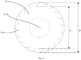
Fig. 4 is a top view of the cross-flow wind turbine inFig. 2 ; -
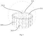
Fig. 5 is an enlarged structural schematic view at portion V inFig. 2 ; -
Fig. 6 is a top view of a cross-flow wind turbine according to another embodiment of the present disclosure. - The implementation, functional features and advantages of the present application will be further described with reference to the accompanying drawings with the embodiments.
- As following, the technical solution in the embodiments of the present disclosure will be described clearly and completely with reference to the drawings in the embodiment of the present application. Obviously, the described embodiment is only a part of the embodiment of the present application, not all of the embodiments. Based on the embodiments in the present application, all other embodiments perceived by those ordinary skills in the art without creative effort should be fallen within the protection scope of the present application.
- It should be noted that all directional indicators (such as upper, lower, left, right, front, rear, etc.) in the embodiment of the present application are only used to explain the relative positional relationship, movement, etc. between various components under a certain specific posture (as shown in the drawings). If the specific posture changes, the directional indicator will also change accordingly.
- In addition, the descriptions related to "first", "second" and the like in the present application are for descriptive purposes only and cannot be understood as indicating or implying its relative importance or implicitly indicating a number of technical features indicated. Thus, features defining "first" and "second" may explicitly or implicitly include at least one of the features. In the description of the present application, the meaning of "plural" is at least two, such as two, three, etc., otherwise specifically defined.
- In the present application, the terms "connected" and "fixed" etc. should be understood in a broad sense, otherwise specified and defined. For example, "fixed" can be a fixed connection, a detachable connection, or an forming a part integrally; It can be a mechanical connection or an electrical connection; It can be a direct connection or an indirect connection through an intermediate medium; and it can be the communication between interior of two elements or the interaction between two elements, otherwise specifically defined. For those ordinary skilled in the art, the specific meanings of the aforementioned terms in the present application can be understood according to practical conditions.
- In addition, the technical solutions between the various embodiments may be combined with each other, but must be based on what one of ordinary skill in the art can achieve. When the combination of technical solutions is contradictory or impossible to achieve, it should be considered that the combination of such technical solutions does not exist and is not within the protection scope required by the present application.
- The present disclosure proposes a
cross-flow wind turbine 31. - As shown in
Figs. 1 and2 , thecross-flow wind turbine 31 of the present disclosure which is applied to afan heater 100, includes: - a
base 10; - a
shell 50 disposed on thebase 10. - Specifically, the
shell 50 includes afront shell 51 and arear shell 53 connected to thefront shell 51. Thefront shell 51 and therear shell 53 are enclosed to form an accommodating cavity (not shown) for accommodating theair passage assembly 30, the heating assembly (not shown) and the like of thefan heater 100. Thefront shell 51 is provided with an air outlet (not shown), and therear shell 53 is provided with an air inlet (not shown). Air flow enters into the accommodating cavity in theshell 50 from the air inlet of therear shell 53, then sequentially passes through theair passage assembly 30 for acceleration and the heating assembly for heating, and finally blows out from the air outlet of thefront shell 51. - The
air passage assembly 30 of thefan heater 100 includes avolute 33 and across-flow wind turbine 31 provided in thevolute 33. - Specifically, as shown in
Figs. 2 ,3 , and5 , in at least one embodiment of the present disclosure, thecross-flow wind turbine 31 includes includes two fixingplates 311 oppositely disposed and a plurality ofblades 315 connected between the two fixingplates 311, the plurality ofblades 315 being disposed at intervals along an outer edge of the fixingplate 311, in which theblades 315 are disposed twisted along an axial direction of thecross-flow wind turbine 31, and a relative twisting angle at both ends of theblades 315 is no less than 5° and no more than 40°. - The
fan heater 100 being placed horizonatally is describe hereinafter as an example. - In the present embodiment, each fixing
plate 311 is circular and is placed in the horizontal plane, and the two fixingplates 311 are disposed in the vertical direction and two plate surfaces are disposed in parallel. Two ends of eachblade 315 are respectively connected to the two fixingplates 311, and the end of eachblade 315 is located at the outer edge of the fixingplate 311. As such, thecross-flow wind turbine 31 is substantially cylindrical, with its axis extending in the vertical direction. In addition, between the two fixingplates 311, a plurality of reinforcing plates (not shown) are provided, which are parallel to each other and disposed at intervals. The plurality of reinforcing plates pass through eachblade 315, to strengthen the structural strength of thecross-flow wind turbine 31. - Specifically, as shown in
Fig. 2 , theblades 315 are twisted by a certain angle along the circumferential direction of thecross-flow wind turbine 31 for every certain distance rise along the axial direction of thecross-flow wind turbine 31. The twisting starts from the lower end to the upper end, so that the relative twisting angles of the upper and lower ends of each blade 315 (i.e., the two ends respectively close to the two fixing plates 311) is no less than 5° and no more than 40° (i.e., between 5° and 40°). As such, when thecross-flow wind turbine 31 is in operation, each part on asame blade 315 may pass through the minimum gap between thecross-flow wind turbine 31 and thevolute 33 at a different time point, diversifying the types and frequencies of noise generated at each part on thesame blade 315. - As such, it should be understood that according to the technical solution of the present disclosure, each
blade 315 of thecross-flow wind turbine 31 is disposed twisted along the axial direction of thecross-flow wind turbine 31, and the relative twisting angle at the two ends of eachblade 315 no less than 5° and no more than 40°, so that when thecross-flow wind turbine 31 works, each part on thesame blade 315 can pass through the minimum gap between thecross-flow wind turbine 31 and thevolute 33 at different time points, diversifying the types and frequencies of noises generated at each part on the same blade. Thus, the resonance peak caused by noise superposition of a same type and frequency is avoided, i.e. the noise frequency has been less concentrated, with the noise intensity reduced. the working noise of thefan heater 100 is thereby reduced, and the use comfortability for users has been improved. - As shown in
Fig. 3 , theblades 315 are obliquely disposed between the two fixingplates 311 along the axial direction of thecross-flow wind turbine 31, and an inclined angle θ formed between theblades 315 and the fixingplates 311, is no less than 85° and no more than 88°. - Specifically, each
blade 315 has an elongated shape, and eachblade 315 is aninclined blade 315 or aspiral blade 315 obliquely disposed along the axial direction of the cross-flow wind turbine 31 (i.e., the vertical direction, i.e., the up-down direction). Namely, the extending direction of eachblade 315 is not parallel to the axial direction of thecross-flow wind turbine 31, and the included angle θ between eachblade 315 and the fixedplate 311 is no less than 85° and no more than 88°. As such, compared with the vertical blades (i.e., theblades 315 disposed perpendicularly to the fixed plate 311), it firstly further ensures that each part on asame blade 315 may pass through the minimum gap between thecross-flow wind turbine 31 and thevolute 33 at a different time point, thus further avoiding the generation and superposition of noise of a same type and frequency, avoiding the frequency concentrated noise and reducing the noise intensity. Further, such arrangement can also enable eachblade 315 in the circumferential direction of thecross-flow wind turbine 31 to pass through the minimum gap between thecross-flow wind turbine 31 and thevolute 33 at a different time point, thus avoiding the noise of a same type and frequency generated by eachblade 315, further avoiding the superposition of the noise of the same type and frequency generated by eachblade 315, and further reducing the noise intensity. - As shown in
Fig. 4 , the cross section of theblade 315 is arc, and the chord length of the arc ranges from 6mm to 8mm. - Specifically, the cross-section of the
blade 315 in the horizontal plane perpendicular to the axis of thecross-flow wind turbine 31 is approximately arc-shaped, and the chord length of the arc ranges from 6mm to 8mm. - The thickness of the
blade 315 ranges from 0.3mm to 0.5mm. - The outer diameter D of the
cross-flow wind turbine 31 ranges from 30mm to 100mm, and/or the length of the cross-flow wind turbine ranges from 150mm to 600mm. - The wheel diameter ratio d/D of the
cross-flow wind turbine 31 ranges from 0.7 to 0.85. - Specifically, further referring to
Fig. 4 , the side of eachblade 315 close to the axis of thecross-flow wind turbine 31 is approximately located on circumference of a same circle, and the ratio d/D regarding the diameter d of the circle to the outer diameter D of thecross-flow wind turbine 31 ranges from 0.7 to 0.85. - Through such setting of the above parameters, the air volume of the
cross-flow wind turbine 31 can be effectively increased, bringing less material consumption and a lighter weight, thus effectively reducing the load of the drivingmotor 35 at a fixed air volume, and further reducing the working noise of thefan heater 100. - As shown in
Fig. 4 , the number ofblades 315 of thecross-flow wind turbine 31 ranges from 18 to 25. Such arrangement enables the air intake and sweeping of theblades 315, so that thecross-flow wind turbine 31 can generate a larger air volume. Thereby the load of themotor 35 is reduced under a certain air volume condition, further reducing the working noise of thefan heater 100. - As shown in
Fig. 6 , in at least another embodiment of thecross-flow wind turbine 31 of the present disclosure, thecross-flow wind turbine 31 includes a plurality offirst blades 315a and a plurality ofsecond blades 315b, the width of thefirst blades 315a is greater than the width of thesecond blades 315b, and the plurality offirst blades 315a and the plurality ofsecond blades 315b are alternately disposed. - Specifically, the chord length of the
first blade 315a is set to 7.4mm, and its wheel diameter ratio is set to 0.79; while the chord length of thesecond blade 315b is set to 7.0mm, with a wheel diameter ratio being set to 0.78. - As such, the large and small blades are alternately disposed, which not only can maintain a higher air volume, but also can utilize the large and small blades to alternately perform the air sweeping, effectively disperses the noise frequency due to the air sweeping by the
blades 315, and reduces the howling sound induced by excessively strong noise at the same frequency band, thereby effectively reducing the working noise of thefan heater 100. - In addition, in at least yet another embodiment of the
cross-flow wind turbine 31 of the present disclosure, a distance between two of the first blades and the second blades is alternately changed. Specifically, theblades 315 can be alternately disposed at an alternatively changed intervals at 5.0mm and 5.3mm. As such, the noise intensity can also be dispersed to alleviate noise. - The present disclosure further proposes a
fan heater 100, which includes ashell 50 and anair passage assembly 30 disposed in theshell 50, in which theair passage assembly 30 includes avolute 33 and across-flow wind turbine 31 as described above. Since thefan heater 100 takes all the technical solutions of the aforementioned embodiments, it has at least all the beneficial effects brought by the technical solutions of these embodiments, which will thus not be described in detail herein. Thecross-flow wind turbine 31 is disposed in thevolute 33. - As shown in
Figs. 2 and5 , one end of thecross-flow wind turbine 31 is provided with arotating shaft 3111, thevolute 33 is provided with abearing sleeve 331, and therotating shaft 3111 is accommodated in thebearing sleeve 331. - In the present embodiment, a
rotating shaft 3111 is fixedly disposed on a fixingplate 311 positioned at the upper end of thecross-flow wind turbine 31, therotating shaft 3111 is protruded on the surface of the fixingplate 311 facing thevolute 33. Correspondingly, abearing sleeve 331 is fixedly disposed at the position of thevolute 33 facing therotating shaft 3111, and a bearing is fixedly disposed in thebearing sleeve 331. Therotating shaft 3111 is accommodated in thebearing sleeve 331 and inserted into the inner ring of the bearing. Specifically, thebearing sleeve 331 may be a rubber bearing sleeve. - As such, the vibration in the rotation of the
cross-flow wind turbine 31 can be effectively reduced, which enables the rotation of thecross-flow wind turbine 31 and the structure of thefan heater 100 more stable. Further, the reduction in vibration as well as the more stable structure would lead to the alleviation of the noise of thefan heater 100. - As shown in
Figs. 2 and3 , ashaft sleeve 3113 is disposed at an end of thecross-flow wind turbine 31 where therotating shaft 3111 is not disposed. Theair passage assembly 30 further includes amotor 35 disposed in thevolute 33; theshaft sleeve 3113 is sleeved on anoutput shaft 351 of themotor 35. - In the present embodiment, the fixing
plate 311 located at one end of thecross-flow wind turbine 31 where therotating shaft 3111 is not disposed. Theshaft sleeve 3113 is sleeved and fit on theoutput shaft 351 of themotor 35. As such, as themotor 35 rotates, theoutput shaft 351 of themotor 35 drives theshaft sleeve 3113 to rotate. Then theshaft sleeve 3113 fixed on the fixed plate drives thecross-flow wind turbine 31 to rotate. Therotating shaft 3111 at the other end then rotates in thebearing sleeve 331. Specifically, thesleeve 3113 can be a silicone sleeve, and is connected with theoutput shaft 351 of themotor 35 in an interference fit without screws, and the assembly is simple and convenient. Further, the saving of parts and components reduces the vibration between these parts and components and also alleviate the load of themotor 35 on the other hand, effectively alleviating the noise of thefan heater 100. - The above is only the preferred embodiment of the present application and is not therefore limiting the scope of the present application. Any equivalent structure or process change made by using the contents of the present specification and drawings, or directly or indirectly applied in other related technical fields, shall be included in the protection scope of the present application.
| Reference Numeral | Name | Reference | Name | |
| 100 | | 315b | | |
| 10 | | 33 | Volute | |
| 30 | | 331 | | |
| 31 | | 35 | | |
| 311 | | 351 | | |
| 3111 | | 50 | | |
| 3113 | | 51 | | |
| 315 | | 53 | | |
| 315a | First blade |
Claims (20)
- A cross-flow wind turbine applied to a fan heater, comprising
two fixing plates oppositely disposed, and
a plurality of blades connected between the two fixing plates, the plurality of blades being disposed at intervals along an outer edge of each fixing plate,
wherein the blades are twisted along an axial direction of the cross-flow wind turbine, and a relative twisting angle at both ends of one of the blades is no less than 5° and no more than 40°. - The cross-flow wind turbine of claim 1,
wherein the blades are obliquely disposed between the two fixing plates along the axial direction of the cross-flow wind turbine, and
wherein an included angle θ formed between one of the blades and one of the fixing plates, is no less than 85° and no more than 88°. - The cross-flow wind turbine of claim 1,
wherein a cross section of one of the blades has an arc shape with a chord length 6 mm to 8 mm. - The cross-flow wind turbine of claim 3, wherein
a wheel diameter ratio d/D of the cross-flow wind turbine ranges from 0.7 to 0.85. - The cross-flow wind turbine of claim 1, wherein
a thickness of one of the blades ranges from 0.3 mm to 0.5 mm. - The cross-flow wind turbine of claim 1,
wherein an outer diameter D of the cross-flow wind turbine ranges from 30 mm to 100 mm, and/or
wherein a length of the cross-flow wind turbine ranges from 150 mm to 600 mm. - The cross-flow wind turbine of claim 1, wherein
the cross-flow wind turbine comprises no less than 18 and no more than 25 blades. - The cross-flow wind turbine of claim 1, wherein
a wheel diameter ratio d/D of the cross-flow wind turbine ranges from 0.7 to 0.85. - The cross-flow wind turbine of claim 1,
wherein the cross-flow wind turbine comprises a plurality of first blades and a plurality of second blades,
wherein one of the first blades and one of the second blades are alternately disposed; a width of the one of the first blades is greater than a width of the one of the second blades; and/or,
wherein distances between two of the first blades and the second blades are alternately changed. - A fan heater, comprising
a shell, and
an air passage assembly disposed in the shell and comprising a volute and a cross-flow wind turbine as claimed in claim 1, the cross-flow wind turbine (31) is disposed in the volute. - The fan heater of claim 10, further comprising:a rotating shaft disposed at a first end of the cross-flow wind turbine, anda bearing sleeve disposed on the volute to accommodate the rotating shaft.
- The fan heater of claim 11,
wherein a shaft sleeve is disposed at a second end of the cross-flow wind turbine, and
wherein the air passage assembly further comprises a motor disposed in the volute; the shaft sleeve is sleeved on an output shaft of the motor. - The fan heater of claim 10, wherein
the blades are obliquely disposed between the two fixing plates along the axial direction of the cross-flow wind turbine, wherein
an inclined angle θ formed between the blades and the fixing plates, is no less than 85° and no more than 88°. - The fan heater of claim 10, wherein
a cross section of one of the blades has an arc shape with a chord length 6 mm to 8 mm. - The fan heater of claim 14, wherein
a wheel diameter ratio d/D of the cross-flow wind turbine ranges from 0.7 to 0.85. - The fan heater of claim 10, wherein
a thickness of one of the blades ranges from 0.3 mm to 0.5 mm. - The fan heater of claim 10, wherein
an outer diameter D of the cross-flow wind turbine ranges from 30mm to 100mm, and/or a length of the cross-flow wind turbine ranges from 150mm to 600mm. - The fan heater of claim 10, wherein
the cross-flow wind turbine comprises no less than 18 and no more than 25 blades. - The fan heater of claim 10, wherein
a wheel diameter ratio d/D of the cross-flow wind turbine ranges from 0.7 to 0.85. - The fan heater of claim 10, wherein
the cross-flow wind turbine comprises
a plurality of first blades and a plurality of second blades, wherein
one of the first blades and one of the second blades are alternately disposed; a width of the one of the first blades is greater than a width of the one of the second blades; and/or,
a distance between two of the first blades and the second blades is alternately changed.
Applications Claiming Priority (2)
| Application Number | Priority Date | Filing Date | Title |
|---|---|---|---|
| CN201720796411.5U CN206917925U (en) | 2017-06-30 | 2017-06-30 | Tubular wine wheel and warm-air drier |
| PCT/CN2018/083795 WO2019001107A1 (en) | 2017-06-30 | 2018-04-19 | Cross-flow wind turbine and fan heater |
Publications (3)
| Publication Number | Publication Date |
|---|---|
| EP3633206A1 true EP3633206A1 (en) | 2020-04-08 |
| EP3633206A4 EP3633206A4 (en) | 2020-06-17 |
| EP3633206B1 EP3633206B1 (en) | 2024-03-06 |
Family
ID=61335195
Family Applications (1)
| Application Number | Title | Priority Date | Filing Date |
|---|---|---|---|
| EP18823842.2A Active EP3633206B1 (en) | 2017-06-30 | 2018-04-19 | Cross-flow fan and fan heater |
Country Status (5)
| Country | Link |
|---|---|
| US (1) | US20200158137A1 (en) |
| EP (1) | EP3633206B1 (en) |
| JP (1) | JP2020521912A (en) |
| CN (1) | CN206917925U (en) |
| WO (1) | WO2019001107A1 (en) |
Families Citing this family (6)
| Publication number | Priority date | Publication date | Assignee | Title |
|---|---|---|---|---|
| CN206917925U (en) * | 2017-06-30 | 2018-01-23 | 广东美的环境电器制造有限公司 | Tubular wine wheel and warm-air drier |
| CN108662670A (en) * | 2018-07-13 | 2018-10-16 | 珠海格力电器股份有限公司 | cabinet air conditioner |
| CN108757557A (en) * | 2018-07-20 | 2018-11-06 | 中山市山竹电器科技有限公司 | Cross flow wind wheel and manufacturing method thereof |
| CN109209990B (en) * | 2018-10-26 | 2024-07-02 | 珠海格力电器股份有限公司 | Cross-flow fan blade, cross-flow fan and air conditioner |
| CN214533560U (en) * | 2021-04-16 | 2021-10-29 | 深圳市和生创新技术有限公司 | a heater |
| CN115540343A (en) * | 2021-06-29 | 2022-12-30 | 艾美特电器(深圳)有限公司 | Heating type through-flow air drum |
Family Cites Families (19)
| Publication number | Priority date | Publication date | Assignee | Title |
|---|---|---|---|---|
| US2980990A (en) * | 1957-01-22 | 1961-04-25 | Vernco Corp | Spiral blower wheel |
| JPS4992507U (en) * | 1972-11-30 | 1974-08-10 | ||
| JPS5612098A (en) * | 1979-07-11 | 1981-02-05 | Toshiba Corp | Crossflow fan |
| JPS6090590U (en) * | 1983-11-29 | 1985-06-21 | 三菱重工業株式会社 | Once-through blower |
| JP3107711B2 (en) * | 1994-08-09 | 2000-11-13 | 株式会社東芝 | Cross flow fan |
| JP2799143B2 (en) * | 1994-08-09 | 1998-09-17 | 株式会社東芝 | Apparatus and method for manufacturing multi-blade impeller for cross-flow fan |
| JPH10103287A (en) * | 1996-10-02 | 1998-04-21 | Hitachi Ltd | Once-through fan |
| JP3588251B2 (en) * | 1998-03-24 | 2004-11-10 | 三洋電機株式会社 | Blower |
| KR100459179B1 (en) * | 2002-04-16 | 2004-12-03 | 엘지전자 주식회사 | cross-flow fan |
| CN2888138Y (en) * | 2005-01-06 | 2007-04-11 | 拉斯科控股公司 | Space saving vertically oriented fan |
| JP4687675B2 (en) * | 2007-03-28 | 2011-05-25 | 三菱電機株式会社 | Cross-flow blower and air conditioner |
| CN201221497Y (en) * | 2008-06-20 | 2009-04-15 | 李龚川 | Novel impeller |
| KR101485609B1 (en) * | 2008-11-26 | 2015-01-22 | 엘지전자 주식회사 | Indoor unit for air conditioning apparatus |
| CN201372965Y (en) * | 2008-12-02 | 2009-12-30 | 美的集团有限公司 | Cross flow wind wheel |
| JP2013079617A (en) * | 2011-10-05 | 2013-05-02 | Hitachi Appliances Inc | Air conditioner |
| KR102143389B1 (en) * | 2013-03-20 | 2020-08-28 | 삼성전자주식회사 | Circular Fan and Air Conditioner Having the Same |
| CN204610386U (en) * | 2015-04-21 | 2015-09-02 | 海信(广东)空调有限公司 | Cross-flow fan mounting structure and air conditioner indoor unit |
| CN206111665U (en) * | 2016-09-07 | 2017-04-19 | 佛山市东丽塑胶有限公司 | Changeable through -flow fan blade in air inlet angle |
| CN206917925U (en) * | 2017-06-30 | 2018-01-23 | 广东美的环境电器制造有限公司 | Tubular wine wheel and warm-air drier |
-
2017
- 2017-06-30 CN CN201720796411.5U patent/CN206917925U/en active Active
-
2018
- 2018-04-19 US US16/623,404 patent/US20200158137A1/en not_active Abandoned
- 2018-04-19 WO PCT/CN2018/083795 patent/WO2019001107A1/en not_active Ceased
- 2018-04-19 JP JP2019565827A patent/JP2020521912A/en active Pending
- 2018-04-19 EP EP18823842.2A patent/EP3633206B1/en active Active
Also Published As
| Publication number | Publication date |
|---|---|
| EP3633206A4 (en) | 2020-06-17 |
| WO2019001107A1 (en) | 2019-01-03 |
| CN206917925U (en) | 2018-01-23 |
| JP2020521912A (en) | 2020-07-27 |
| EP3633206B1 (en) | 2024-03-06 |
| US20200158137A1 (en) | 2020-05-21 |
Similar Documents
| Publication | Publication Date | Title |
|---|---|---|
| EP3633206A1 (en) | Cross-flow wind turbine and fan heater | |
| CN201318324Y (en) | a fan blade | |
| EP3839261B1 (en) | Counter-rotating fan | |
| JP2003074495A (en) | Blade structure of turbo fan | |
| EP2885502B1 (en) | Blower motor assembly having air directing surface | |
| CN108458420A (en) | Air-conditioner outdoor unit and air conditioner | |
| CN106015048A (en) | Low noise air-conditioning cooling axial flow fan | |
| CN107061324B (en) | Axial flow fan and air conditioner having the same | |
| CN106961175A (en) | Magneto outer rotor and the magneto for adjusting magnetic shoe shape | |
| EP3730849B1 (en) | Fresh air module, air conditioner indoor unit, and air conditioner | |
| JP2015086803A (en) | Impeller and axial flow fan provided with the impeller | |
| CN110307178A (en) | A kind of low-noise impeller | |
| CN111895545A (en) | Motor mounting rack, fan assembly and air purifier | |
| CN207146525U (en) | Ceiling machine | |
| EP4166792B1 (en) | Centrifugal wind wheel and air treatment device having same | |
| CN205876800U (en) | Machine in tubular wine wheel, through -flow fan and air conditioning | |
| US20030190241A1 (en) | Fan guide | |
| CN203466672U (en) | Motor end cover structure improving ventilation effect | |
| CN206280299U (en) | A kind of super-silent flabellum and fan | |
| JP2011202507A (en) | Multiblade blower | |
| JPH0243016Y2 (en) | ||
| CN210118279U (en) | Fan blades, fan components, air duct components and air conditioners | |
| CN206017257U (en) | Centrifugal wind wheel and air-conditioner | |
| CN215870952U (en) | Rotor assembly and rotor structure | |
| CN207349164U (en) | Centrifugal fan blade and centrifugal fan with same |
Legal Events
| Date | Code | Title | Description |
|---|---|---|---|
| STAA | Information on the status of an ep patent application or granted ep patent |
Free format text: STATUS: THE INTERNATIONAL PUBLICATION HAS BEEN MADE |
|
| PUAI | Public reference made under article 153(3) epc to a published international application that has entered the european phase |
Free format text: ORIGINAL CODE: 0009012 |
|
| STAA | Information on the status of an ep patent application or granted ep patent |
Free format text: STATUS: REQUEST FOR EXAMINATION WAS MADE |
|
| 17P | Request for examination filed |
Effective date: 20191230 |
|
| AK | Designated contracting states |
Kind code of ref document: A1 Designated state(s): AL AT BE BG CH CY CZ DE DK EE ES FI FR GB GR HR HU IE IS IT LI LT LU LV MC MK MT NL NO PL PT RO RS SE SI SK SM TR |
|
| AX | Request for extension of the european patent |
Extension state: BA ME |
|
| REG | Reference to a national code |
Ref country code: DE Ref legal event code: R079 Free format text: PREVIOUS MAIN CLASS: F04D0029280000 Ipc: F04D0017040000 Ref country code: DE Ref legal event code: R079 Ref document number: 602018066312 Country of ref document: DE Free format text: PREVIOUS MAIN CLASS: F04D0029280000 Ipc: F04D0017040000 |
|
| A4 | Supplementary search report drawn up and despatched |
Effective date: 20200518 |
|
| RIC1 | Information provided on ipc code assigned before grant |
Ipc: F04D 17/04 20060101AFI20200512BHEP Ipc: F04D 29/66 20060101ALI20200512BHEP Ipc: F04D 29/28 20060101ALI20200512BHEP Ipc: F04D 29/30 20060101ALI20200512BHEP |
|
| DAV | Request for validation of the european patent (deleted) | ||
| DAX | Request for extension of the european patent (deleted) | ||
| STAA | Information on the status of an ep patent application or granted ep patent |
Free format text: STATUS: EXAMINATION IS IN PROGRESS |
|
| 17Q | First examination report despatched |
Effective date: 20220506 |
|
| GRAP | Despatch of communication of intention to grant a patent |
Free format text: ORIGINAL CODE: EPIDOSNIGR1 |
|
| STAA | Information on the status of an ep patent application or granted ep patent |
Free format text: STATUS: GRANT OF PATENT IS INTENDED |
|
| INTG | Intention to grant announced |
Effective date: 20231207 |
|
| GRAS | Grant fee paid |
Free format text: ORIGINAL CODE: EPIDOSNIGR3 |
|
| GRAA | (expected) grant |
Free format text: ORIGINAL CODE: 0009210 |
|
| STAA | Information on the status of an ep patent application or granted ep patent |
Free format text: STATUS: THE PATENT HAS BEEN GRANTED |
|
| AK | Designated contracting states |
Kind code of ref document: B1 Designated state(s): AL AT BE BG CH CY CZ DE DK EE ES FI FR GB GR HR HU IE IS IT LI LT LU LV MC MK MT NL NO PL PT RO RS SE SI SK SM TR |
|
| REG | Reference to a national code |
Ref country code: GB Ref legal event code: FG4D |
|
| REG | Reference to a national code |
Ref country code: CH Ref legal event code: EP |
|
| REG | Reference to a national code |
Ref country code: DE Ref legal event code: R096 Ref document number: 602018066312 Country of ref document: DE |
|
| REG | Reference to a national code |
Ref country code: IE Ref legal event code: FG4D |
|
| REG | Reference to a national code |
Ref country code: LT Ref legal event code: MG9D |
|
| PG25 | Lapsed in a contracting state [announced via postgrant information from national office to epo] |
Ref country code: LT Free format text: LAPSE BECAUSE OF FAILURE TO SUBMIT A TRANSLATION OF THE DESCRIPTION OR TO PAY THE FEE WITHIN THE PRESCRIBED TIME-LIMIT Effective date: 20240306 |
|
| REG | Reference to a national code |
Ref country code: NL Ref legal event code: MP Effective date: 20240306 |
|
| PG25 | Lapsed in a contracting state [announced via postgrant information from national office to epo] |
Ref country code: GR Free format text: LAPSE BECAUSE OF FAILURE TO SUBMIT A TRANSLATION OF THE DESCRIPTION OR TO PAY THE FEE WITHIN THE PRESCRIBED TIME-LIMIT Effective date: 20240607 |
|
| PG25 | Lapsed in a contracting state [announced via postgrant information from national office to epo] |
Ref country code: HR Free format text: LAPSE BECAUSE OF FAILURE TO SUBMIT A TRANSLATION OF THE DESCRIPTION OR TO PAY THE FEE WITHIN THE PRESCRIBED TIME-LIMIT Effective date: 20240306 Ref country code: RS Free format text: LAPSE BECAUSE OF FAILURE TO SUBMIT A TRANSLATION OF THE DESCRIPTION OR TO PAY THE FEE WITHIN THE PRESCRIBED TIME-LIMIT Effective date: 20240606 |
|
| PG25 | Lapsed in a contracting state [announced via postgrant information from national office to epo] |
Ref country code: ES Free format text: LAPSE BECAUSE OF FAILURE TO SUBMIT A TRANSLATION OF THE DESCRIPTION OR TO PAY THE FEE WITHIN THE PRESCRIBED TIME-LIMIT Effective date: 20240306 |
|
| PG25 | Lapsed in a contracting state [announced via postgrant information from national office to epo] |
Ref country code: RS Free format text: LAPSE BECAUSE OF FAILURE TO SUBMIT A TRANSLATION OF THE DESCRIPTION OR TO PAY THE FEE WITHIN THE PRESCRIBED TIME-LIMIT Effective date: 20240606 Ref country code: NO Free format text: LAPSE BECAUSE OF FAILURE TO SUBMIT A TRANSLATION OF THE DESCRIPTION OR TO PAY THE FEE WITHIN THE PRESCRIBED TIME-LIMIT Effective date: 20240606 Ref country code: LT Free format text: LAPSE BECAUSE OF FAILURE TO SUBMIT A TRANSLATION OF THE DESCRIPTION OR TO PAY THE FEE WITHIN THE PRESCRIBED TIME-LIMIT Effective date: 20240306 Ref country code: HR Free format text: LAPSE BECAUSE OF FAILURE TO SUBMIT A TRANSLATION OF THE DESCRIPTION OR TO PAY THE FEE WITHIN THE PRESCRIBED TIME-LIMIT Effective date: 20240306 Ref country code: GR Free format text: LAPSE BECAUSE OF FAILURE TO SUBMIT A TRANSLATION OF THE DESCRIPTION OR TO PAY THE FEE WITHIN THE PRESCRIBED TIME-LIMIT Effective date: 20240607 Ref country code: FI Free format text: LAPSE BECAUSE OF FAILURE TO SUBMIT A TRANSLATION OF THE DESCRIPTION OR TO PAY THE FEE WITHIN THE PRESCRIBED TIME-LIMIT Effective date: 20240306 Ref country code: ES Free format text: LAPSE BECAUSE OF FAILURE TO SUBMIT A TRANSLATION OF THE DESCRIPTION OR TO PAY THE FEE WITHIN THE PRESCRIBED TIME-LIMIT Effective date: 20240306 Ref country code: BG Free format text: LAPSE BECAUSE OF FAILURE TO SUBMIT A TRANSLATION OF THE DESCRIPTION OR TO PAY THE FEE WITHIN THE PRESCRIBED TIME-LIMIT Effective date: 20240306 |
|
| REG | Reference to a national code |
Ref country code: AT Ref legal event code: MK05 Ref document number: 1663772 Country of ref document: AT Kind code of ref document: T Effective date: 20240306 |
|
| PG25 | Lapsed in a contracting state [announced via postgrant information from national office to epo] |
Ref country code: SE Free format text: LAPSE BECAUSE OF FAILURE TO SUBMIT A TRANSLATION OF THE DESCRIPTION OR TO PAY THE FEE WITHIN THE PRESCRIBED TIME-LIMIT Effective date: 20240306 Ref country code: LV Free format text: LAPSE BECAUSE OF FAILURE TO SUBMIT A TRANSLATION OF THE DESCRIPTION OR TO PAY THE FEE WITHIN THE PRESCRIBED TIME-LIMIT Effective date: 20240306 |
|
| PG25 | Lapsed in a contracting state [announced via postgrant information from national office to epo] |
Ref country code: NL Free format text: LAPSE BECAUSE OF FAILURE TO SUBMIT A TRANSLATION OF THE DESCRIPTION OR TO PAY THE FEE WITHIN THE PRESCRIBED TIME-LIMIT Effective date: 20240306 |
|
| PG25 | Lapsed in a contracting state [announced via postgrant information from national office to epo] |
Ref country code: NL Free format text: LAPSE BECAUSE OF FAILURE TO SUBMIT A TRANSLATION OF THE DESCRIPTION OR TO PAY THE FEE WITHIN THE PRESCRIBED TIME-LIMIT Effective date: 20240306 |
|
| PG25 | Lapsed in a contracting state [announced via postgrant information from national office to epo] |
Ref country code: IS Free format text: LAPSE BECAUSE OF FAILURE TO SUBMIT A TRANSLATION OF THE DESCRIPTION OR TO PAY THE FEE WITHIN THE PRESCRIBED TIME-LIMIT Effective date: 20240706 |
|
| PG25 | Lapsed in a contracting state [announced via postgrant information from national office to epo] |
Ref country code: PT Free format text: LAPSE BECAUSE OF FAILURE TO SUBMIT A TRANSLATION OF THE DESCRIPTION OR TO PAY THE FEE WITHIN THE PRESCRIBED TIME-LIMIT Effective date: 20240708 Ref country code: SM Free format text: LAPSE BECAUSE OF FAILURE TO SUBMIT A TRANSLATION OF THE DESCRIPTION OR TO PAY THE FEE WITHIN THE PRESCRIBED TIME-LIMIT Effective date: 20240306 |
|
| PG25 | Lapsed in a contracting state [announced via postgrant information from national office to epo] |
Ref country code: CZ Free format text: LAPSE BECAUSE OF FAILURE TO SUBMIT A TRANSLATION OF THE DESCRIPTION OR TO PAY THE FEE WITHIN THE PRESCRIBED TIME-LIMIT Effective date: 20240306 Ref country code: EE Free format text: LAPSE BECAUSE OF FAILURE TO SUBMIT A TRANSLATION OF THE DESCRIPTION OR TO PAY THE FEE WITHIN THE PRESCRIBED TIME-LIMIT Effective date: 20240306 |
|
| PG25 | Lapsed in a contracting state [announced via postgrant information from national office to epo] |
Ref country code: AT Free format text: LAPSE BECAUSE OF FAILURE TO SUBMIT A TRANSLATION OF THE DESCRIPTION OR TO PAY THE FEE WITHIN THE PRESCRIBED TIME-LIMIT Effective date: 20240306 |
|
| PG25 | Lapsed in a contracting state [announced via postgrant information from national office to epo] |
Ref country code: PL Free format text: LAPSE BECAUSE OF FAILURE TO SUBMIT A TRANSLATION OF THE DESCRIPTION OR TO PAY THE FEE WITHIN THE PRESCRIBED TIME-LIMIT Effective date: 20240306 |
|
| PG25 | Lapsed in a contracting state [announced via postgrant information from national office to epo] |
Ref country code: SK Free format text: LAPSE BECAUSE OF FAILURE TO SUBMIT A TRANSLATION OF THE DESCRIPTION OR TO PAY THE FEE WITHIN THE PRESCRIBED TIME-LIMIT Effective date: 20240306 |
|
| PG25 | Lapsed in a contracting state [announced via postgrant information from national office to epo] |
Ref country code: SM Free format text: LAPSE BECAUSE OF FAILURE TO SUBMIT A TRANSLATION OF THE DESCRIPTION OR TO PAY THE FEE WITHIN THE PRESCRIBED TIME-LIMIT Effective date: 20240306 Ref country code: SK Free format text: LAPSE BECAUSE OF FAILURE TO SUBMIT A TRANSLATION OF THE DESCRIPTION OR TO PAY THE FEE WITHIN THE PRESCRIBED TIME-LIMIT Effective date: 20240306 Ref country code: RO Free format text: LAPSE BECAUSE OF FAILURE TO SUBMIT A TRANSLATION OF THE DESCRIPTION OR TO PAY THE FEE WITHIN THE PRESCRIBED TIME-LIMIT Effective date: 20240306 Ref country code: PT Free format text: LAPSE BECAUSE OF FAILURE TO SUBMIT A TRANSLATION OF THE DESCRIPTION OR TO PAY THE FEE WITHIN THE PRESCRIBED TIME-LIMIT Effective date: 20240708 Ref country code: PL Free format text: LAPSE BECAUSE OF FAILURE TO SUBMIT A TRANSLATION OF THE DESCRIPTION OR TO PAY THE FEE WITHIN THE PRESCRIBED TIME-LIMIT Effective date: 20240306 Ref country code: IS Free format text: LAPSE BECAUSE OF FAILURE TO SUBMIT A TRANSLATION OF THE DESCRIPTION OR TO PAY THE FEE WITHIN THE PRESCRIBED TIME-LIMIT Effective date: 20240706 Ref country code: EE Free format text: LAPSE BECAUSE OF FAILURE TO SUBMIT A TRANSLATION OF THE DESCRIPTION OR TO PAY THE FEE WITHIN THE PRESCRIBED TIME-LIMIT Effective date: 20240306 Ref country code: CZ Free format text: LAPSE BECAUSE OF FAILURE TO SUBMIT A TRANSLATION OF THE DESCRIPTION OR TO PAY THE FEE WITHIN THE PRESCRIBED TIME-LIMIT Effective date: 20240306 Ref country code: AT Free format text: LAPSE BECAUSE OF FAILURE TO SUBMIT A TRANSLATION OF THE DESCRIPTION OR TO PAY THE FEE WITHIN THE PRESCRIBED TIME-LIMIT Effective date: 20240306 |
|
| REG | Reference to a national code |
Ref country code: CH Ref legal event code: PL |
|
| PG25 | Lapsed in a contracting state [announced via postgrant information from national office to epo] |
Ref country code: IT Free format text: LAPSE BECAUSE OF FAILURE TO SUBMIT A TRANSLATION OF THE DESCRIPTION OR TO PAY THE FEE WITHIN THE PRESCRIBED TIME-LIMIT Effective date: 20240306 |
|
| REG | Reference to a national code |
Ref country code: DE Ref legal event code: R097 Ref document number: 602018066312 Country of ref document: DE |
|
| PG25 | Lapsed in a contracting state [announced via postgrant information from national office to epo] |
Ref country code: LU Free format text: LAPSE BECAUSE OF NON-PAYMENT OF DUE FEES Effective date: 20240419 |
|
| REG | Reference to a national code |
Ref country code: BE Ref legal event code: MM Effective date: 20240430 |
|
| PG25 | Lapsed in a contracting state [announced via postgrant information from national office to epo] |
Ref country code: LU Free format text: LAPSE BECAUSE OF NON-PAYMENT OF DUE FEES Effective date: 20240419 Ref country code: IT Free format text: LAPSE BECAUSE OF FAILURE TO SUBMIT A TRANSLATION OF THE DESCRIPTION OR TO PAY THE FEE WITHIN THE PRESCRIBED TIME-LIMIT Effective date: 20240306 |
|
| PG25 | Lapsed in a contracting state [announced via postgrant information from national office to epo] |
Ref country code: MC Free format text: LAPSE BECAUSE OF FAILURE TO SUBMIT A TRANSLATION OF THE DESCRIPTION OR TO PAY THE FEE WITHIN THE PRESCRIBED TIME-LIMIT Effective date: 20240306 |
|
| PLBE | No opposition filed within time limit |
Free format text: ORIGINAL CODE: 0009261 |
|
| STAA | Information on the status of an ep patent application or granted ep patent |
Free format text: STATUS: NO OPPOSITION FILED WITHIN TIME LIMIT |
|
| PG25 | Lapsed in a contracting state [announced via postgrant information from national office to epo] |
Ref country code: DK Free format text: LAPSE BECAUSE OF FAILURE TO SUBMIT A TRANSLATION OF THE DESCRIPTION OR TO PAY THE FEE WITHIN THE PRESCRIBED TIME-LIMIT Effective date: 20240306 |
|
| PG25 | Lapsed in a contracting state [announced via postgrant information from national office to epo] |
Ref country code: BE Free format text: LAPSE BECAUSE OF NON-PAYMENT OF DUE FEES Effective date: 20240430 |
|
| PG25 | Lapsed in a contracting state [announced via postgrant information from national office to epo] |
Ref country code: MC Free format text: LAPSE BECAUSE OF FAILURE TO SUBMIT A TRANSLATION OF THE DESCRIPTION OR TO PAY THE FEE WITHIN THE PRESCRIBED TIME-LIMIT Effective date: 20240306 Ref country code: DK Free format text: LAPSE BECAUSE OF FAILURE TO SUBMIT A TRANSLATION OF THE DESCRIPTION OR TO PAY THE FEE WITHIN THE PRESCRIBED TIME-LIMIT Effective date: 20240306 Ref country code: BE Free format text: LAPSE BECAUSE OF NON-PAYMENT OF DUE FEES Effective date: 20240430 Ref country code: CH Free format text: LAPSE BECAUSE OF NON-PAYMENT OF DUE FEES Effective date: 20240430 |
|
| 26N | No opposition filed |
Effective date: 20241209 |
|
| PG25 | Lapsed in a contracting state [announced via postgrant information from national office to epo] |
Ref country code: IE Free format text: LAPSE BECAUSE OF NON-PAYMENT OF DUE FEES Effective date: 20240419 |
|
| PG25 | Lapsed in a contracting state [announced via postgrant information from national office to epo] |
Ref country code: SI Free format text: LAPSE BECAUSE OF FAILURE TO SUBMIT A TRANSLATION OF THE DESCRIPTION OR TO PAY THE FEE WITHIN THE PRESCRIBED TIME-LIMIT Effective date: 20240306 |
|
| PGFP | Annual fee paid to national office [announced via postgrant information from national office to epo] |
Ref country code: DE Payment date: 20250417 Year of fee payment: 8 |
|
| PGFP | Annual fee paid to national office [announced via postgrant information from national office to epo] |
Ref country code: FR Payment date: 20250430 Year of fee payment: 8 |
|
| PG25 | Lapsed in a contracting state [announced via postgrant information from national office to epo] |
Ref country code: CY Free format text: LAPSE BECAUSE OF FAILURE TO SUBMIT A TRANSLATION OF THE DESCRIPTION OR TO PAY THE FEE WITHIN THE PRESCRIBED TIME-LIMIT; INVALID AB INITIO Effective date: 20180419 |
|
| PG25 | Lapsed in a contracting state [announced via postgrant information from national office to epo] |
Ref country code: HU Free format text: LAPSE BECAUSE OF FAILURE TO SUBMIT A TRANSLATION OF THE DESCRIPTION OR TO PAY THE FEE WITHIN THE PRESCRIBED TIME-LIMIT; INVALID AB INITIO Effective date: 20180419 |
|
| PGFP | Annual fee paid to national office [announced via postgrant information from national office to epo] |
Ref country code: GB Payment date: 20260327 Year of fee payment: 9 |