EP3633181A1 - End plug for a fuel rail, fuel rail and method of fabricating a fuel rail for an internal combustion engine - Google Patents
End plug for a fuel rail, fuel rail and method of fabricating a fuel rail for an internal combustion engine Download PDFInfo
- Publication number
- EP3633181A1 EP3633181A1 EP18198277.8A EP18198277A EP3633181A1 EP 3633181 A1 EP3633181 A1 EP 3633181A1 EP 18198277 A EP18198277 A EP 18198277A EP 3633181 A1 EP3633181 A1 EP 3633181A1
- Authority
- EP
- European Patent Office
- Prior art keywords
- fuel
- end plug
- fuel rail
- rail
- resilient
- Prior art date
- Legal status (The legal status is an assumption and is not a legal conclusion. Google has not performed a legal analysis and makes no representation as to the accuracy of the status listed.)
- Withdrawn
Links
Images
Classifications
-
- F—MECHANICAL ENGINEERING; LIGHTING; HEATING; WEAPONS; BLASTING
- F02—COMBUSTION ENGINES; HOT-GAS OR COMBUSTION-PRODUCT ENGINE PLANTS
- F02M—SUPPLYING COMBUSTION ENGINES IN GENERAL WITH COMBUSTIBLE MIXTURES OR CONSTITUENTS THEREOF
- F02M55/00—Fuel-injection apparatus characterised by their fuel conduits or their venting means; Arrangements of conduits between fuel tank and pump F02M37/00
- F02M55/02—Conduits between injection pumps and injectors, e.g. conduits between pump and common-rail or conduits between common-rail and injectors
- F02M55/025—Common rails
-
- F—MECHANICAL ENGINEERING; LIGHTING; HEATING; WEAPONS; BLASTING
- F02—COMBUSTION ENGINES; HOT-GAS OR COMBUSTION-PRODUCT ENGINE PLANTS
- F02M—SUPPLYING COMBUSTION ENGINES IN GENERAL WITH COMBUSTIBLE MIXTURES OR CONSTITUENTS THEREOF
- F02M37/00—Apparatus or systems for feeding liquid fuel from storage containers to carburettors or fuel-injection apparatus; Arrangements for purifying liquid fuel specially adapted for, or arranged on, internal-combustion engines
- F02M37/0011—Constructional details; Manufacturing or assembly of elements of fuel systems; Materials therefor
- F02M37/0041—Means for damping pressure pulsations
-
- F—MECHANICAL ENGINEERING; LIGHTING; HEATING; WEAPONS; BLASTING
- F02—COMBUSTION ENGINES; HOT-GAS OR COMBUSTION-PRODUCT ENGINE PLANTS
- F02M—SUPPLYING COMBUSTION ENGINES IN GENERAL WITH COMBUSTIBLE MIXTURES OR CONSTITUENTS THEREOF
- F02M55/00—Fuel-injection apparatus characterised by their fuel conduits or their venting means; Arrangements of conduits between fuel tank and pump F02M37/00
- F02M55/04—Means for damping vibrations or pressure fluctuations in injection pump inlets or outlets
-
- F—MECHANICAL ENGINEERING; LIGHTING; HEATING; WEAPONS; BLASTING
- F16—ENGINEERING ELEMENTS AND UNITS; GENERAL MEASURES FOR PRODUCING AND MAINTAINING EFFECTIVE FUNCTIONING OF MACHINES OR INSTALLATIONS; THERMAL INSULATION IN GENERAL
- F16L—PIPES; JOINTS OR FITTINGS FOR PIPES; SUPPORTS FOR PIPES, CABLES OR PROTECTIVE TUBING; MEANS FOR THERMAL INSULATION IN GENERAL
- F16L55/00—Devices or appurtenances for use in, or in connection with, pipes or pipe systems
- F16L55/02—Energy absorbers; Noise absorbers
- F16L55/033—Noise absorbers
- F16L55/0338—Noise absorbers by means of a membrane
-
- F—MECHANICAL ENGINEERING; LIGHTING; HEATING; WEAPONS; BLASTING
- F16—ENGINEERING ELEMENTS AND UNITS; GENERAL MEASURES FOR PRODUCING AND MAINTAINING EFFECTIVE FUNCTIONING OF MACHINES OR INSTALLATIONS; THERMAL INSULATION IN GENERAL
- F16L—PIPES; JOINTS OR FITTINGS FOR PIPES; SUPPORTS FOR PIPES, CABLES OR PROTECTIVE TUBING; MEANS FOR THERMAL INSULATION IN GENERAL
- F16L55/00—Devices or appurtenances for use in, or in connection with, pipes or pipe systems
- F16L55/04—Devices damping pulsations or vibrations in fluids
-
- F—MECHANICAL ENGINEERING; LIGHTING; HEATING; WEAPONS; BLASTING
- F16—ENGINEERING ELEMENTS AND UNITS; GENERAL MEASURES FOR PRODUCING AND MAINTAINING EFFECTIVE FUNCTIONING OF MACHINES OR INSTALLATIONS; THERMAL INSULATION IN GENERAL
- F16L—PIPES; JOINTS OR FITTINGS FOR PIPES; SUPPORTS FOR PIPES, CABLES OR PROTECTIVE TUBING; MEANS FOR THERMAL INSULATION IN GENERAL
- F16L55/00—Devices or appurtenances for use in, or in connection with, pipes or pipe systems
- F16L55/04—Devices damping pulsations or vibrations in fluids
- F16L55/045—Devices damping pulsations or vibrations in fluids specially adapted to prevent or minimise the effects of water hammer
- F16L55/05—Buffers therefor
- F16L55/052—Pneumatic reservoirs
- F16L55/053—Pneumatic reservoirs the gas in the reservoir being separated from the fluid in the pipe
-
- F—MECHANICAL ENGINEERING; LIGHTING; HEATING; WEAPONS; BLASTING
- F02—COMBUSTION ENGINES; HOT-GAS OR COMBUSTION-PRODUCT ENGINE PLANTS
- F02M—SUPPLYING COMBUSTION ENGINES IN GENERAL WITH COMBUSTIBLE MIXTURES OR CONSTITUENTS THEREOF
- F02M2200/00—Details of fuel-injection apparatus, not otherwise provided for
- F02M2200/26—Fuel-injection apparatus with elastically deformable elements other than coil springs
-
- F—MECHANICAL ENGINEERING; LIGHTING; HEATING; WEAPONS; BLASTING
- F02—COMBUSTION ENGINES; HOT-GAS OR COMBUSTION-PRODUCT ENGINE PLANTS
- F02M—SUPPLYING COMBUSTION ENGINES IN GENERAL WITH COMBUSTIBLE MIXTURES OR CONSTITUENTS THEREOF
- F02M2200/00—Details of fuel-injection apparatus, not otherwise provided for
- F02M2200/31—Fuel-injection apparatus having hydraulic pressure fluctuations damping elements
-
- F—MECHANICAL ENGINEERING; LIGHTING; HEATING; WEAPONS; BLASTING
- F02—COMBUSTION ENGINES; HOT-GAS OR COMBUSTION-PRODUCT ENGINE PLANTS
- F02M—SUPPLYING COMBUSTION ENGINES IN GENERAL WITH COMBUSTIBLE MIXTURES OR CONSTITUENTS THEREOF
- F02M2200/00—Details of fuel-injection apparatus, not otherwise provided for
- F02M2200/31—Fuel-injection apparatus having hydraulic pressure fluctuations damping elements
- F02M2200/315—Fuel-injection apparatus having hydraulic pressure fluctuations damping elements for damping fuel pressure fluctuations
-
- F—MECHANICAL ENGINEERING; LIGHTING; HEATING; WEAPONS; BLASTING
- F02—COMBUSTION ENGINES; HOT-GAS OR COMBUSTION-PRODUCT ENGINE PLANTS
- F02M—SUPPLYING COMBUSTION ENGINES IN GENERAL WITH COMBUSTIBLE MIXTURES OR CONSTITUENTS THEREOF
- F02M2200/00—Details of fuel-injection apparatus, not otherwise provided for
- F02M2200/80—Fuel injection apparatus manufacture, repair or assembly
- F02M2200/8084—Fuel injection apparatus manufacture, repair or assembly involving welding or soldering
-
- F—MECHANICAL ENGINEERING; LIGHTING; HEATING; WEAPONS; BLASTING
- F02—COMBUSTION ENGINES; HOT-GAS OR COMBUSTION-PRODUCT ENGINE PLANTS
- F02M—SUPPLYING COMBUSTION ENGINES IN GENERAL WITH COMBUSTIBLE MIXTURES OR CONSTITUENTS THEREOF
- F02M37/00—Apparatus or systems for feeding liquid fuel from storage containers to carburettors or fuel-injection apparatus; Arrangements for purifying liquid fuel specially adapted for, or arranged on, internal-combustion engines
- F02M37/0011—Constructional details; Manufacturing or assembly of elements of fuel systems; Materials therefor
- F02M37/0017—Constructional details; Manufacturing or assembly of elements of fuel systems; Materials therefor related to fuel pipes or their connections, e.g. joints or sealings
-
- F—MECHANICAL ENGINEERING; LIGHTING; HEATING; WEAPONS; BLASTING
- F02—COMBUSTION ENGINES; HOT-GAS OR COMBUSTION-PRODUCT ENGINE PLANTS
- F02M—SUPPLYING COMBUSTION ENGINES IN GENERAL WITH COMBUSTIBLE MIXTURES OR CONSTITUENTS THEREOF
- F02M69/00—Low-pressure fuel-injection apparatus ; Apparatus with both continuous and intermittent injection; Apparatus injecting different types of fuel
- F02M69/46—Details, component parts or accessories not provided for in, or of interest apart from, the apparatus covered by groups F02M69/02 - F02M69/44
- F02M69/462—Arrangement of fuel conduits, e.g. with valves for maintaining pressure in the pipes after the engine being shut-down
- F02M69/465—Arrangement of fuel conduits, e.g. with valves for maintaining pressure in the pipes after the engine being shut-down of fuel rails
Definitions
- the present disclosure relates to an end plug for a fuel rail, a fuel rail and a method of fabricating a fuel fail for an internal combustion engine.
- Fuel injection assemblies are widely used for injecting fuel into an internal combustion engine.
- the fuel injection assembly may have a fuel injector for each cylinder of a multi-cylinder engine in which the fuel is supplied to the injectors from a reservoir in the form of a fuel rail, also known as a common rail, comprising an elongate generally tubular member, to which each of the injectors is connected.
- Fuel is supplied to the fuel rail by a fuel pump, and the movement of the fuel into, through and out of the fuel rail into the fuel injectors, frequently results in pressure oscillations in the fuel pressure in the fuel rail. Particularly in systems which have uncontrolled variations in the fuel pressure supplied to the individual injectors can occur, as a result of the pressure oscillations in the region of the outlet to the injectors. These pressure variations may have adverse effects on the performance of the injectors which can lead to excessive fuel injection or too little fuel injection with the risk of causing potential damage to the engine.
- the present disclosure seeks to provide a solution to this problem.
- the present disclosure provides a solution to this problem by providing a fuel injection assembly with a fuel pressure oscillation damping device which is less complex than the known solutions and more cost-effective both in production costs and assembly time.
- a fuel rail for a fuel injection assembly for an internal combustion engine has a fuel reservoir in the form of an elongate generally tubular member comprising a fuel rail, having a fuel inlet and a plurality of fuel outlets each adapted to be connected to a fuel injector.
- the fuel rail has a fuel pressure oscillation damping device in the form of a resilient element incorporated in an end plug secured to the fuel rail.
- the resilient element is able to damp oscillations in the fuel pressure in the fuel rail.
- the damping element By positioning the damping means in the end plug of the fuel rail, the damping element can be easily included in the fuel rail at the same time as joining the end plug to the elongate generally tubular member of the fuel rail.
- An improved harmonization of the internal pressure of the fuel rail is provided so as to better control the pressure of the fuel at the injector and better control the combustion process. Emissions can be reduced.
- the end plug with the resilient element can be provided as a separate component.
- the present disclosure also provides an end plug adapted to be connected to a fuel rail of a fuel injection assembly for an internal combustion engine, the end plug having damping means comprising a resilient element to dampen oscillations in the fuel pressure in the fuel rail.
- An end plug can be secured to one or both ends of the elongate generally tubular member depending on the design of the fuel rail.
- the resilient element comes into contact with the fuel in the fuel reservoir in order to dampen oscillations in the pressure of the fuel within the fuel rail.
- the resilient element may comprise a material that is compatible with the fuel, for example have sufficient corrosion resistance to the fuel.
- the resilient element may comprise stainless steel for example.
- the resilient element can have different forms.
- the resilient element is formed by a planar element secured to a spring.
- the planar element is movable in response to fluctuations in the fuel pressure in the fuel rail, the spring damping out the movement of the disc-like element.
- the planar element may comprise a substantially rigid disc and may be clamped to the spring.
- the planar element may comprise stainless steel and the spring may comprise a spring steel.
- the spring may be a coil spring such as a helical spring.
- the resilient element comprises a resilient membrane secured about its periphery to the end plug, the resilient membrane being responsive and resiliently deforming in response to fuel pressure in the fuel rail and in particular changes in the fuel pressure in the fuel rail to dampen oscillations in the fuel pressure.
- the periphery of the resilient membrane may be welded to an interior surface of the end plug.
- the resilient membrane may be formed of a metal such as stainless steel.
- the resilient membrane may have a thickness selected such that the membrane can resiliently deform in response to the fuel pressure.
- a fuel rail having a fuel reservoir in the form of an elongate generally tubular member having a fuel inlet and a plurality of fuel outlets each adapted to be connected to a fuel injector is provided.
- the fuel rail has an end plug in accordance with any one of the embodiments described herein.
- the fuel rail has a single end plug secured to one end of the tubular member. The opposing end of the tubular member provides the fuel inlet.
- the fuel rail comprises two end plugs and the fuel inlet is arranged between the end plugs in a wall of the tubular member.
- the resilient member included in each end plug may have the same or a different form.
- each end plug may include a resilient membrane or one end plug may include a resilient member and the second end plug a planar element and spring.
- the resilient and damping effect provided by the resilient members of the two end plugs may the substantially the same or may vary.
- the fuel rail may be used in a low pressure fuel rail assembly in which the fuel has a pressure in the range of 5 to 10 bar, for example.
- the fuel rail may also be used in a high pressure fuel rail assembly in which the fuel has a pressure of around 200 bar or more.
- a method of fabricating a fuel rail or a fuel rail assembly for an internal combustion engine comprises securing an end plug according anyone of the embodiments described herein to a an elongate generally tubular member having a fuel inlet and a plurality of fuel outlets each adapted to be connected to a fuel injector.
- the end plug may be secured to the tubular member by welding or brazing.
- one end plug is secured to both ends of the tubular member.
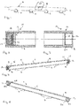
- a fuel rail assembly having a fuel rail tube 2 in the form of an elongate generally tubular member 8 having four fuel outlets 4 and a fuel inlet 6.
- a fuel injector not illustrated in Figure 1 , is secured to each of the fuel outlets.
- the fuel rail may include fewer or more than fuel outlets.
- the fuel rail 2 incorporates a damping device to damp out pressure oscillations in the fuel in the fuel rail 2.
- the damping device 10 is positioned in the vicinity of an end plug 12 secured to the elongate tubular member 8.
- the damping device 10 may be positioned in and, in some embodiments, secured within the end plug 12.
- the damping device 10 includes a resilient member 14 for damping pressure oscillations in the fuel rail 2 to which the end plug 12 is secured.
- the resilient member 14 may have different forms.
- Figures 2 and 4 illustrate a first embodiment and Figures 3 and 5 a second embodiment of a fuel rail 2 with an end plug 12 incorporating a resilient member 14.
- the resilient member 14 comprises a planar disc-like member 16 that is mechanically coupled with a coil spring 18.
- the planar member 16 is responsive to oscillations of the pressure of the fuel in the fuel rail 2 and is able to move relative to the fuel rail 2, in particular relative to the tubular member 8, against the resilient movement of the coil spring 18 to absorb or damp oscillations in the fuel pressure.
- the planar member 16 may be formed of a metal such as stainless steel and the coil spring 18 may be formed of a spring steel. The planar member 16 may be clamped to the coil spring 18.
- the resilient membrane 20 is formed of a thin sheet of metal such as stainless steel which is secured about its periphery to an interior surface 22 of the end plug 12.
- the membrane 20 is in itself resilient and is responsive to oscillations in the pressure of the fuel in the fuel rail 2.
- the resilient movement of the membrane material 20 serves to absorb pressure oscillations in the fuel in the fuel rail 2.
- FIG 4 there is shown a schematic perspective view of a fuel rail 2 incorporating an end plug 12 with an internal damping device 10 in accordance with the embodiment shown in Figure 2 at each end of the fuel rail 2.
- FIG 5 shows a schematic perspective view of a fuel rail 2 having an alternative arrangement which incorporates an internal damping device 10 in accordance with the embodiment shown in Figure 3 at each end of the fuel rail 2.
- Each end of the fuel rail is closed by an end plug 12, each of which incorporates a damping device 10.
- the form of the damping device 10 included at each end of the fuel rail is different.
- a damping device 10 is provided at one end only of the tubular member 8 of the fuel rail 2, a fuel inlet 6 being located at the other end of the tubular member 8.
- the end plug may be secured to the tubular member 8 by welding for example.
- a plug according to the present disclosure incorporating a damping device may be incorporated in a fuel rail intermediate its length.
Landscapes
- Engineering & Computer Science (AREA)
- General Engineering & Computer Science (AREA)
- Mechanical Engineering (AREA)
- Chemical & Material Sciences (AREA)
- Combustion & Propulsion (AREA)
- Fuel-Injection Apparatus (AREA)
Abstract
Description
- The present disclosure relates to an end plug for a fuel rail, a fuel rail and a method of fabricating a fuel fail for an internal combustion engine.
- Fuel injection assemblies are widely used for injecting fuel into an internal combustion engine. The fuel injection assembly may have a fuel injector for each cylinder of a multi-cylinder engine in which the fuel is supplied to the injectors from a reservoir in the form of a fuel rail, also known as a common rail, comprising an elongate generally tubular member, to which each of the injectors is connected.
- Fuel is supplied to the fuel rail by a fuel pump, and the movement of the fuel into, through and out of the fuel rail into the fuel injectors, frequently results in pressure oscillations in the fuel pressure in the fuel rail. Particularly in systems which have uncontrolled variations in the fuel pressure supplied to the individual injectors can occur, as a result of the pressure oscillations in the region of the outlet to the injectors. These pressure variations may have adverse effects on the performance of the injectors which can lead to excessive fuel injection or too little fuel injection with the risk of causing potential damage to the engine.
- The present disclosure seeks to provide a solution to this problem.
- The present disclosure provides a solution to this problem by providing a fuel injection assembly with a fuel pressure oscillation damping device which is less complex than the known solutions and more cost-effective both in production costs and assembly time.
- According to the present disclosure, there is provided a fuel rail for a fuel injection assembly for an internal combustion engine. The fuel rail has a fuel reservoir in the form of an elongate generally tubular member comprising a fuel rail, having a fuel inlet and a plurality of fuel outlets each adapted to be connected to a fuel injector. The fuel rail has a fuel pressure oscillation damping device in the form of a resilient element incorporated in an end plug secured to the fuel rail.
- The resilient element is able to damp oscillations in the fuel pressure in the fuel rail. By positioning the damping means in the end plug of the fuel rail, the damping element can be easily included in the fuel rail at the same time as joining the end plug to the elongate generally tubular member of the fuel rail. An improved harmonization of the internal pressure of the fuel rail is provided so as to better control the pressure of the fuel at the injector and better control the combustion process. Emissions can be reduced.
- The end plug with the resilient element can be provided as a separate component. The present disclosure also provides an end plug adapted to be connected to a fuel rail of a fuel injection assembly for an internal combustion engine, the end plug having damping means comprising a resilient element to dampen oscillations in the fuel pressure in the fuel rail. An end plug can be secured to one or both ends of the elongate generally tubular member depending on the design of the fuel rail.
- The resilient element comes into contact with the fuel in the fuel reservoir in order to dampen oscillations in the pressure of the fuel within the fuel rail. The resilient element may comprise a material that is compatible with the fuel, for example have sufficient corrosion resistance to the fuel. The resilient element may comprise stainless steel for example.
- The resilient element can have different forms. In one embodiment, the resilient element is formed by a planar element secured to a spring. The planar element is movable in response to fluctuations in the fuel pressure in the fuel rail, the spring damping out the movement of the disc-like element. The planar element may comprise a substantially rigid disc and may be clamped to the spring. The planar element may comprise stainless steel and the spring may comprise a spring steel. The spring may be a coil spring such as a helical spring.
- In an embodiment, the resilient element comprises a resilient membrane secured about its periphery to the end plug, the resilient membrane being responsive and resiliently deforming in response to fuel pressure in the fuel rail and in particular changes in the fuel pressure in the fuel rail to dampen oscillations in the fuel pressure.
- The periphery of the resilient membrane may be welded to an interior surface of the end plug.
- The resilient membrane may be formed of a metal such as stainless steel. The resilient membrane may have a thickness selected such that the membrane can resiliently deform in response to the fuel pressure.
- A fuel rail having a fuel reservoir in the form of an elongate generally tubular member having a fuel inlet and a plurality of fuel outlets each adapted to be connected to a fuel injector is provided. The fuel rail has an end plug in accordance with any one of the embodiments described herein.
- In some embodiments, the fuel rail has a single end plug secured to one end of the tubular member. The opposing end of the tubular member provides the fuel inlet.
- In some embodiments, the fuel rail comprises two end plugs and the fuel inlet is arranged between the end plugs in a wall of the tubular member. The resilient member included in each end plug may have the same or a different form. For example, each end plug may include a resilient membrane or one end plug may include a resilient member and the second end plug a planar element and spring. The resilient and damping effect provided by the resilient members of the two end plugs may the substantially the same or may vary.
- The fuel rail may be used in a low pressure fuel rail assembly in which the fuel has a pressure in the range of 5 to 10 bar, for example. The fuel rail may also be used in a high pressure fuel rail assembly in which the fuel has a pressure of around 200 bar or more.
- A method of fabricating a fuel rail or a fuel rail assembly for an internal combustion engine is also provided. The method comprises securing an end plug according anyone of the embodiments described herein to a an elongate generally tubular member having a fuel inlet and a plurality of fuel outlets each adapted to be connected to a fuel injector.
- The end plug may be secured to the tubular member by welding or brazing.
- In some embodiments, one end plug is secured to both ends of the tubular member.
- Embodiments of the disclosure will now be described by way of example with reference to the accompanying drawings in which:
- Figure 1
- illustrates a fuel rail,
- Figure 2
- illustrates a sectional side view of part of a fuel rail with an end plug according to a first embodiment,
- Figure 3
- illustrates a sectional side view of a fuel rail with an end plug according to a second embodiment,
- Figure 4
- illustrates a perspective sectional view of a fuel rail incorporating the end plug of
Figure 2 at each end of the rail, and - Figure 5
- illustrates a perspective sectional view of a fuel rail incorporating the end plug of
Figure 3 at each end of the rail. - Referring now to
Figure 1 , there is shown a fuel rail assembly having afuel rail tube 2 in the form of an elongate generallytubular member 8 having fourfuel outlets 4 and a fuel inlet 6. A fuel injector, not illustrated inFigure 1 , is secured to each of the fuel outlets. In other embodiments, the fuel rail may include fewer or more than fuel outlets. Thefuel rail 2 incorporates a damping device to damp out pressure oscillations in the fuel in thefuel rail 2. Thedamping device 10 is positioned in the vicinity of anend plug 12 secured to the elongatetubular member 8. Thedamping device 10 may be positioned in and, in some embodiments, secured within theend plug 12. Thedamping device 10 includes aresilient member 14 for damping pressure oscillations in thefuel rail 2 to which theend plug 12 is secured. - The
resilient member 14 may have different forms.Figures 2 and 4 illustrate a first embodiment andFigures 3 and 5 a second embodiment of afuel rail 2 with anend plug 12 incorporating aresilient member 14. - Referring now to
Figures 2 and 4 , there is shown a dampingdevice 10 for damping pressure oscillations in thefuel rail 2 to which theend plug 12 is secured. In the first embodiment illustrated infigures 2 and 4 , theresilient member 14 comprises a planar disc-like member 16 that is mechanically coupled with acoil spring 18. Theplanar member 16 is responsive to oscillations of the pressure of the fuel in thefuel rail 2 and is able to move relative to thefuel rail 2, in particular relative to thetubular member 8, against the resilient movement of thecoil spring 18 to absorb or damp oscillations in the fuel pressure. Theplanar member 16 may be formed of a metal such as stainless steel and thecoil spring 18 may be formed of a spring steel. Theplanar member 16 may be clamped to thecoil spring 18. - Referring now to
Figures 3 and 5 , there is shown an alternative embodiment of the dampingdevice 10 which incorporates aresilient membrane 20. Theresilient membrane 20 is formed of a thin sheet of metal such as stainless steel which is secured about its periphery to aninterior surface 22 of theend plug 12. Themembrane 20 is in itself resilient and is responsive to oscillations in the pressure of the fuel in thefuel rail 2. Thus, the resilient movement of themembrane material 20 serves to absorb pressure oscillations in the fuel in thefuel rail 2. - Referring now to
Figure 4 , there is shown a schematic perspective view of afuel rail 2 incorporating anend plug 12 with an internal dampingdevice 10 in accordance with the embodiment shown inFigure 2 at each end of thefuel rail 2. -
Figure 5 shows a schematic perspective view of afuel rail 2 having an alternative arrangement which incorporates an internal dampingdevice 10 in accordance with the embodiment shown inFigure 3 at each end of thefuel rail 2. - Each end of the fuel rail is closed by an
end plug 12, each of which incorporates a dampingdevice 10. In some embodiments, the form of the dampingdevice 10 included at each end of the fuel rail is different. In an alternative arrangement, a dampingdevice 10 is provided at one end only of thetubular member 8 of thefuel rail 2, a fuel inlet 6 being located at the other end of thetubular member 8. - The end plug may be secured to the
tubular member 8 by welding for example. - Although described as an
end plug 12, a plug according to the present disclosure incorporating a damping device may be incorporated in a fuel rail intermediate its length. - By incorporating the damping
device 10 in theend plug 12, a very cost-effective solution is provided as no additional component is necessary, and no extra assembly time is required in the assembly of the fuel rail installation with a consequent saving in material and assembly time costs. -
- 2
- Fuel rail
- 4
- Fuel outlet
- 6
- Fuel inlet
- 8
- Tubular member
- 10
- Damping device
- 12
- End plug
- 14
- Resilient element
- 16
- Planar element
- 18
- Coil spring
- 20
- Membrane
- 22
- Interior surface
Claims (14)
- An end plug (12) adapted to be connected to a fuel rail (2) of a fuel injection assembly for an internal combustion engine, the end plug (12) having damping means (10) comprising a resilient element (14) to dampen oscillations in the fuel pressure in the fuel rail (2).
- An end plug (12) according to claim 1, wherein the resilient element (14) is formed by a planar element (16) secured to a spring (18).
- An end plug (12) according to claim 2, wherein the planar element (16) comprises a substantially rigid disc.
- An end plug (12) according to claim 2 or claim 3, wherein the planar element (16) is formed of stainless steel and the spring is formed of spring steel.
- An end plug (12) according to one of claims 2 to 4, wherein the planar element (16) is clamped to the spring (18).
- An end plug (12) according to one of claims 2 to 5, wherein the resilient element is slidably engaged with an interior surface of the end plug.
- An end plug (12) according to claim 1, wherein the resilient element (14) comprises a resilient membrane (20) secured about its periphery to the end plug (12).
- An end plug (12) according to claim 7, wherein resilient membrane (20) is welded to an interior surface of the end plug (12) about its periphery.
- An end plug (12) according to claim 7 or claim 8, wherein the resilient membrane (20) is formed of a metal such as stainless steel.
- A fuel rail (2) for a fuel rail assembly for an internal combustion engine, the fuel rail (2) comprising a fuel reservoir in the form of an elongate generally tubular member (8) having a fuel inlet (6) and a plurality of fuel outlets (4) each adapted to be connected to a fuel injector, the fuel rail (2) having an end plug (12) in accordance with any one or more of claims 1 to 9.
- A fuel rail (2) according to claim 10, wherein the fuel rail (2) comprises two end plugs (12) and the fuel inlet (6) is arranged between the end plugs (12) in a wall of the tubular member (8).
- A method of fabricating a fuel rail (2) for a fuel rail assembly for an internal combustion engine, the method comprising:
securing an end plug (12) according to one of claims 1 to 9 to an elongate generally tubular member (8) having a fuel inlet and a plurality of fuel outlets (4) each adapted to be connected to a fuel injector (6). - A method according to claim 12, wherein the end plug (12) is secured to the tubular member (8) by welding or brazing.
- A method according to claim 12 or claim 13, wherein one end plug (12) is secured to both ends of the tubular member (8) .
Priority Applications (1)
| Application Number | Priority Date | Filing Date | Title |
|---|---|---|---|
| EP18198277.8A EP3633181A1 (en) | 2018-10-02 | 2018-10-02 | End plug for a fuel rail, fuel rail and method of fabricating a fuel rail for an internal combustion engine |
Applications Claiming Priority (1)
| Application Number | Priority Date | Filing Date | Title |
|---|---|---|---|
| EP18198277.8A EP3633181A1 (en) | 2018-10-02 | 2018-10-02 | End plug for a fuel rail, fuel rail and method of fabricating a fuel rail for an internal combustion engine |
Publications (1)
| Publication Number | Publication Date |
|---|---|
| EP3633181A1 true EP3633181A1 (en) | 2020-04-08 |
Family
ID=63722262
Family Applications (1)
| Application Number | Title | Priority Date | Filing Date |
|---|---|---|---|
| EP18198277.8A Withdrawn EP3633181A1 (en) | 2018-10-02 | 2018-10-02 | End plug for a fuel rail, fuel rail and method of fabricating a fuel rail for an internal combustion engine |
Country Status (1)
| Country | Link |
|---|---|
| EP (1) | EP3633181A1 (en) |
Citations (7)
| Publication number | Priority date | Publication date | Assignee | Title |
|---|---|---|---|---|
| JPS63100262A (en) * | 1986-10-16 | 1988-05-02 | Aisan Ind Co Ltd | Pulsation damping device for fuel feed system |
| EP2080894A1 (en) * | 2008-01-18 | 2009-07-22 | Continental Automotive GmbH | Fuel rail of a combustion engine |
| JP2011157920A (en) * | 2010-02-03 | 2011-08-18 | Isuzu Motors Ltd | Fuel supply system for internal combustion engine, and the internal combustion engine equipped therewith |
| FR2989122A1 (en) * | 2012-04-10 | 2013-10-11 | Coutier Moulage Gen Ind | FUEL INJECTION RAMP FOR INTERNAL COMBUSTION ENGINE |
| US20140014068A1 (en) * | 2012-07-16 | 2014-01-16 | Denso International America, Inc. | Damped fuel delivery system |
| CN103573475A (en) * | 2012-07-26 | 2014-02-12 | 广西玉柴机器股份有限公司 | Pressure-stabilizing fuel gas distributor |
| FR3043732A1 (en) * | 2015-11-13 | 2017-05-19 | Renault Sas | FUEL RAMP WITH PULSATION DAMPING |
-
2018
- 2018-10-02 EP EP18198277.8A patent/EP3633181A1/en not_active Withdrawn
Patent Citations (7)
| Publication number | Priority date | Publication date | Assignee | Title |
|---|---|---|---|---|
| JPS63100262A (en) * | 1986-10-16 | 1988-05-02 | Aisan Ind Co Ltd | Pulsation damping device for fuel feed system |
| EP2080894A1 (en) * | 2008-01-18 | 2009-07-22 | Continental Automotive GmbH | Fuel rail of a combustion engine |
| JP2011157920A (en) * | 2010-02-03 | 2011-08-18 | Isuzu Motors Ltd | Fuel supply system for internal combustion engine, and the internal combustion engine equipped therewith |
| FR2989122A1 (en) * | 2012-04-10 | 2013-10-11 | Coutier Moulage Gen Ind | FUEL INJECTION RAMP FOR INTERNAL COMBUSTION ENGINE |
| US20140014068A1 (en) * | 2012-07-16 | 2014-01-16 | Denso International America, Inc. | Damped fuel delivery system |
| CN103573475A (en) * | 2012-07-26 | 2014-02-12 | 广西玉柴机器股份有限公司 | Pressure-stabilizing fuel gas distributor |
| FR3043732A1 (en) * | 2015-11-13 | 2017-05-19 | Renault Sas | FUEL RAMP WITH PULSATION DAMPING |
Similar Documents
| Publication | Publication Date | Title |
|---|---|---|
| KR102114554B1 (en) | Valve for a high-pressure pump for a motor vehicle, and method for producing a valve for a high-pressure pump | |
| US4984744A (en) | Electromagnetically actuatable valve | |
| KR102202762B1 (en) | Check valves, high pressure components and high pressure fuel pumps | |
| US7520268B1 (en) | Fuel rail damping assembly including an insert | |
| US7175112B2 (en) | Fuel injection valve | |
| US9074565B2 (en) | Damped fuel delivery system | |
| US9518544B2 (en) | Fuel rail with pressure pulsation damper | |
| EP2948675A1 (en) | Fuel injection system comprising a fuel-guiding component, a fuel injection valve and a mounting | |
| KR20070118975A (en) | valve | |
| US8844502B2 (en) | Fuel rail mount | |
| EP2875233A1 (en) | Fuel rail assembly | |
| US10190557B2 (en) | Fuel injector mounting device and fuel rail | |
| US9803605B2 (en) | Fluid injection assembly | |
| JP2016520764A (en) | Fuel piping configuration of common rail fuel supply system | |
| US20090301438A1 (en) | Fuel rail of a combustion engine | |
| EP2839142B1 (en) | Multipart insulating element, in particular for a fuel injection device | |
| EP2766593B1 (en) | Hydraulic coupling | |
| CN104685202B (en) | For the nozzle assembly and fluid ejector of fluid ejector | |
| KR20170125964A (en) | Gasoline direct injection rail | |
| US9938941B2 (en) | Fuel injection system having a fuel-carrying component, a fuel injector and a connecting element | |
| DE102008042154A1 (en) | Fuel injector | |
| US3439876A (en) | Check valve assembly for engine fuel injectors | |
| US10132281B2 (en) | Fluid injector | |
| JP2014088791A (en) | Common rail for fuel injection device | |
| US20170292486A1 (en) | Fuel Injection Valve And Fuel-Injection System |
Legal Events
| Date | Code | Title | Description |
|---|---|---|---|
| PUAI | Public reference made under article 153(3) epc to a published international application that has entered the european phase |
Free format text: ORIGINAL CODE: 0009012 |
|
| STAA | Information on the status of an ep patent application or granted ep patent |
Free format text: STATUS: THE APPLICATION HAS BEEN PUBLISHED |
|
| AK | Designated contracting states |
Kind code of ref document: A1 Designated state(s): AL AT BE BG CH CY CZ DE DK EE ES FI FR GB GR HR HU IE IS IT LI LT LU LV MC MK MT NL NO PL PT RO RS SE SI SK SM TR |
|
| AX | Request for extension of the european patent |
Extension state: BA ME |
|
| RAP1 | Party data changed (applicant data changed or rights of an application transferred) |
Owner name: VITESCO TECHNOLOGIES GMBH |
|
| STAA | Information on the status of an ep patent application or granted ep patent |
Free format text: STATUS: REQUEST FOR EXAMINATION WAS MADE |
|
| 17P | Request for examination filed |
Effective date: 20201008 |
|
| RBV | Designated contracting states (corrected) |
Designated state(s): AL AT BE BG CH CY CZ DE DK EE ES FI FR GB GR HR HU IE IS IT LI LT LU LV MC MK MT NL NO PL PT RO RS SE SI SK SM TR |
|
| STAA | Information on the status of an ep patent application or granted ep patent |
Free format text: STATUS: EXAMINATION IS IN PROGRESS |
|
| 17Q | First examination report despatched |
Effective date: 20210128 |
|
| RAP3 | Party data changed (applicant data changed or rights of an application transferred) |
Owner name: VITESCO TECHNOLOGIES GMBH |
|
| STAA | Information on the status of an ep patent application or granted ep patent |
Free format text: STATUS: THE APPLICATION IS DEEMED TO BE WITHDRAWN |
|
| 18D | Application deemed to be withdrawn |
Effective date: 20210810 |