EP3633150A1 - Noyau de surface portante à plusieurs parois - Google Patents
Noyau de surface portante à plusieurs parois Download PDFInfo
- Publication number
- EP3633150A1 EP3633150A1 EP19200847.2A EP19200847A EP3633150A1 EP 3633150 A1 EP3633150 A1 EP 3633150A1 EP 19200847 A EP19200847 A EP 19200847A EP 3633150 A1 EP3633150 A1 EP 3633150A1
- Authority
- EP
- European Patent Office
- Prior art keywords
- core
- airfoil
- trailing edge
- serpentine
- hybrid skin
- Prior art date
- Legal status (The legal status is an assumption and is not a legal conclusion. Google has not performed a legal analysis and makes no representation as to the accuracy of the status listed.)
- Granted
Links
- WYTGDNHDOZPMIW-RCBQFDQVSA-N alstonine Natural products C1=CC2=C3C=CC=CC3=NC2=C2N1C[C@H]1[C@H](C)OC=C(C(=O)OC)[C@H]1C2 WYTGDNHDOZPMIW-RCBQFDQVSA-N 0.000 claims abstract description 36
- 238000000034 method Methods 0.000 claims abstract description 27
- 239000011162 core material Substances 0.000 claims description 297
- 238000001816 cooling Methods 0.000 claims description 100
- 239000000919 ceramic Substances 0.000 claims description 12
- 238000002347 injection Methods 0.000 claims description 12
- 239000007924 injection Substances 0.000 claims description 12
- VYPSYNLAJGMNEJ-UHFFFAOYSA-N Silicium dioxide Chemical compound O=[Si]=O VYPSYNLAJGMNEJ-UHFFFAOYSA-N 0.000 claims description 10
- 238000005495 investment casting Methods 0.000 claims description 8
- PNEYBMLMFCGWSK-UHFFFAOYSA-N aluminium oxide Inorganic materials [O-2].[O-2].[O-2].[Al+3].[Al+3] PNEYBMLMFCGWSK-UHFFFAOYSA-N 0.000 claims description 6
- 229910001092 metal group alloy Inorganic materials 0.000 claims description 4
- 239000000377 silicon dioxide Substances 0.000 claims description 4
- 238000004891 communication Methods 0.000 claims description 3
- 239000012530 fluid Substances 0.000 claims description 2
- 238000004519 manufacturing process Methods 0.000 description 17
- 239000007789 gas Substances 0.000 description 15
- 239000007787 solid Substances 0.000 description 10
- 239000010408 film Substances 0.000 description 8
- 239000000463 material Substances 0.000 description 8
- 229910052751 metal Inorganic materials 0.000 description 8
- 239000002184 metal Substances 0.000 description 8
- 230000008569 process Effects 0.000 description 7
- 238000013461 design Methods 0.000 description 6
- 239000000446 fuel Substances 0.000 description 6
- 230000009467 reduction Effects 0.000 description 6
- 239000000567 combustion gas Substances 0.000 description 4
- 238000012546 transfer Methods 0.000 description 4
- 239000011800 void material Substances 0.000 description 4
- 239000000654 additive Substances 0.000 description 3
- 230000000996 additive effect Effects 0.000 description 3
- 238000005266 casting Methods 0.000 description 3
- 238000010926 purge Methods 0.000 description 3
- 230000003416 augmentation Effects 0.000 description 2
- 230000008901 benefit Effects 0.000 description 2
- 238000006073 displacement reaction Methods 0.000 description 2
- 230000004907 flux Effects 0.000 description 2
- 238000001746 injection moulding Methods 0.000 description 2
- 238000005457 optimization Methods 0.000 description 2
- BASFCYQUMIYNBI-UHFFFAOYSA-N platinum Chemical compound [Pt] BASFCYQUMIYNBI-UHFFFAOYSA-N 0.000 description 2
- 239000010453 quartz Substances 0.000 description 2
- 239000003870 refractory metal Substances 0.000 description 2
- 230000000717 retained effect Effects 0.000 description 2
- 238000000110 selective laser sintering Methods 0.000 description 2
- 239000002002 slurry Substances 0.000 description 2
- 230000003068 static effect Effects 0.000 description 2
- 229910000990 Ni alloy Inorganic materials 0.000 description 1
- 239000000956 alloy Substances 0.000 description 1
- 229910002065 alloy metal Inorganic materials 0.000 description 1
- 238000000149 argon plasma sintering Methods 0.000 description 1
- 230000008859 change Effects 0.000 description 1
- 230000006835 compression Effects 0.000 description 1
- 238000007906 compression Methods 0.000 description 1
- 239000012809 cooling fluid Substances 0.000 description 1
- 238000012937 correction Methods 0.000 description 1
- 230000003292 diminished effect Effects 0.000 description 1
- 230000008030 elimination Effects 0.000 description 1
- 238000003379 elimination reaction Methods 0.000 description 1
- 239000000284 extract Substances 0.000 description 1
- 238000007730 finishing process Methods 0.000 description 1
- 230000004927 fusion Effects 0.000 description 1
- 230000006872 improvement Effects 0.000 description 1
- 238000005304 joining Methods 0.000 description 1
- 238000002386 leaching Methods 0.000 description 1
- 230000007246 mechanism Effects 0.000 description 1
- 239000007769 metal material Substances 0.000 description 1
- 238000012986 modification Methods 0.000 description 1
- 230000004048 modification Effects 0.000 description 1
- 230000003647 oxidation Effects 0.000 description 1
- 238000007254 oxidation reaction Methods 0.000 description 1
- 239000002245 particle Substances 0.000 description 1
- 229910052697 platinum Inorganic materials 0.000 description 1
- 239000000843 powder Substances 0.000 description 1
- 230000004044 response Effects 0.000 description 1
- 238000007711 solidification Methods 0.000 description 1
- 230000008023 solidification Effects 0.000 description 1
- 230000006641 stabilisation Effects 0.000 description 1
- 238000011105 stabilization Methods 0.000 description 1
- 239000010409 thin film Substances 0.000 description 1
- 238000011144 upstream manufacturing Methods 0.000 description 1
Images


Classifications
-
- F—MECHANICAL ENGINEERING; LIGHTING; HEATING; WEAPONS; BLASTING
- F01—MACHINES OR ENGINES IN GENERAL; ENGINE PLANTS IN GENERAL; STEAM ENGINES
- F01D—NON-POSITIVE DISPLACEMENT MACHINES OR ENGINES, e.g. STEAM TURBINES
- F01D5/00—Blades; Blade-carrying members; Heating, heat-insulating, cooling or antivibration means on the blades or the members
- F01D5/12—Blades
- F01D5/14—Form or construction
- F01D5/18—Hollow blades, i.e. blades with cooling or heating channels or cavities; Heating, heat-insulating or cooling means on blades
- F01D5/187—Convection cooling
- F01D5/188—Convection cooling with an insert in the blade cavity to guide the cooling fluid, e.g. forming a separation wall
- F01D5/189—Convection cooling with an insert in the blade cavity to guide the cooling fluid, e.g. forming a separation wall the insert having a tubular cross-section, e.g. airfoil shape
-
- F—MECHANICAL ENGINEERING; LIGHTING; HEATING; WEAPONS; BLASTING
- F01—MACHINES OR ENGINES IN GENERAL; ENGINE PLANTS IN GENERAL; STEAM ENGINES
- F01D—NON-POSITIVE DISPLACEMENT MACHINES OR ENGINES, e.g. STEAM TURBINES
- F01D5/00—Blades; Blade-carrying members; Heating, heat-insulating, cooling or antivibration means on the blades or the members
- F01D5/12—Blades
- F01D5/14—Form or construction
- F01D5/18—Hollow blades, i.e. blades with cooling or heating channels or cavities; Heating, heat-insulating or cooling means on blades
-
- B—PERFORMING OPERATIONS; TRANSPORTING
- B22—CASTING; POWDER METALLURGY
- B22C—FOUNDRY MOULDING
- B22C9/00—Moulds or cores; Moulding processes
- B22C9/02—Sand moulds or like moulds for shaped castings
- B22C9/04—Use of lost patterns
- B22C9/046—Use of patterns which are eliminated by the liquid metal in the mould
-
- B—PERFORMING OPERATIONS; TRANSPORTING
- B22—CASTING; POWDER METALLURGY
- B22C—FOUNDRY MOULDING
- B22C9/00—Moulds or cores; Moulding processes
- B22C9/10—Cores; Manufacture or installation of cores
-
- B—PERFORMING OPERATIONS; TRANSPORTING
- B22—CASTING; POWDER METALLURGY
- B22C—FOUNDRY MOULDING
- B22C9/00—Moulds or cores; Moulding processes
- B22C9/10—Cores; Manufacture or installation of cores
- B22C9/103—Multipart cores
-
- B—PERFORMING OPERATIONS; TRANSPORTING
- B22—CASTING; POWDER METALLURGY
- B22D—CASTING OF METALS; CASTING OF OTHER SUBSTANCES BY THE SAME PROCESSES OR DEVICES
- B22D25/00—Special casting characterised by the nature of the product
- B22D25/02—Special casting characterised by the nature of the product by its peculiarity of shape; of works of art
-
- F—MECHANICAL ENGINEERING; LIGHTING; HEATING; WEAPONS; BLASTING
- F05—INDEXING SCHEMES RELATING TO ENGINES OR PUMPS IN VARIOUS SUBCLASSES OF CLASSES F01-F04
- F05D—INDEXING SCHEME FOR ASPECTS RELATING TO NON-POSITIVE-DISPLACEMENT MACHINES OR ENGINES, GAS-TURBINES OR JET-PROPULSION PLANTS
- F05D2220/00—Application
- F05D2220/30—Application in turbines
- F05D2220/32—Application in turbines in gas turbines
-
- F—MECHANICAL ENGINEERING; LIGHTING; HEATING; WEAPONS; BLASTING
- F05—INDEXING SCHEMES RELATING TO ENGINES OR PUMPS IN VARIOUS SUBCLASSES OF CLASSES F01-F04
- F05D—INDEXING SCHEME FOR ASPECTS RELATING TO NON-POSITIVE-DISPLACEMENT MACHINES OR ENGINES, GAS-TURBINES OR JET-PROPULSION PLANTS
- F05D2230/00—Manufacture
- F05D2230/20—Manufacture essentially without removing material
- F05D2230/21—Manufacture essentially without removing material by casting
- F05D2230/211—Manufacture essentially without removing material by casting by precision casting, e.g. microfusing or investment casting
-
- F—MECHANICAL ENGINEERING; LIGHTING; HEATING; WEAPONS; BLASTING
- F05—INDEXING SCHEMES RELATING TO ENGINES OR PUMPS IN VARIOUS SUBCLASSES OF CLASSES F01-F04
- F05D—INDEXING SCHEME FOR ASPECTS RELATING TO NON-POSITIVE-DISPLACEMENT MACHINES OR ENGINES, GAS-TURBINES OR JET-PROPULSION PLANTS
- F05D2250/00—Geometry
- F05D2250/10—Two-dimensional
- F05D2250/18—Two-dimensional patterned
- F05D2250/185—Two-dimensional patterned serpentine-like
-
- Y—GENERAL TAGGING OF NEW TECHNOLOGICAL DEVELOPMENTS; GENERAL TAGGING OF CROSS-SECTIONAL TECHNOLOGIES SPANNING OVER SEVERAL SECTIONS OF THE IPC; TECHNICAL SUBJECTS COVERED BY FORMER USPC CROSS-REFERENCE ART COLLECTIONS [XRACs] AND DIGESTS
- Y02—TECHNOLOGIES OR APPLICATIONS FOR MITIGATION OR ADAPTATION AGAINST CLIMATE CHANGE
- Y02T—CLIMATE CHANGE MITIGATION TECHNOLOGIES RELATED TO TRANSPORTATION
- Y02T50/00—Aeronautics or air transport
- Y02T50/60—Efficient propulsion technologies, e.g. for aircraft
Definitions
- This application relates to a multi-walled airfoil core and a method for producing a multi-walled airfoil.
- Gas turbine engines typically include a compressor section, a combustor section, and a turbine section.
- air is pressurized in the compressor section and is mixed with fuel and burned in the combustor section to generate hot combustion gases.
- the hot combustion gases flow through the turbine section, which extracts energy from the hot combustion gases to power the compressor section and other gas turbine engine loads.
- cooling schemes that circulate airflow to cool the component during engine operation. Thermal energy is transferred from the component to the airflow as the airflow circulates through the cooling scheme to cool the component.
- Gas turbine engine airfoils such as turbine blades and turbine vanes, can be fabricated by investment casting.
- a ceramic or refractory metal core is arranged in a mold and coated with a wax material, which provides a desired shape.
- the wax material is then coated with another material, such as a metallic or ceramic slurry that is hardened into a shell.
- the wax is melted out of the shell and molten metal is then poured into the remaining cavity.
- the metal solidifies to form the airfoil.
- the core is then removed, leaving internal passages within the airfoil. Typically, the passages are used for cooling the airfoil.
- a method of forming an airfoil includes forming a hybrid skin core, a tip flag core, and a trailing edge core.
- the hybrid skin core, tip flag core, and trailing edge core are connected to form a first core portion.
- a leading edge core and a serpentine core are formed.
- the first core portion, the leading edge core, and the serpentine core are assembled together to form an airfoil core.
- An airfoil is formed around the airfoil core.
- the airfoil is formed by investment casting.
- the hybrid skin core, tip flag core, trailing edge core, leading edge core, and serpentine core are injection molded.
- the trailing edge core and the hybrid skin core are formed concurrently in a first die.
- the tip flag core, trailing edge core, and hybrid skin core are formed concurrently in the first die.
- leading edge core and the serpentine core are formed concurrently in a second die.
- leading edge core and the serpentine core are connected to form a second core portion.
- a rod is inserted into the leading edge core before forming the airfoil.
- the rod extends to a feature radially outward of tip flag core.
- the rod is removed after forming the airfoil to form a port near a leading edge of the airfoil.
- assembling the airfoil core comprises inserting a rod into the serpentine core and the tip flag core.
- the airfoil core contains one of ceramic, alumina, silica, and a metallic alloy.
- an airfoil core in another exemplary embodiment, includes a first core portion that has a hybrid skin core, a tip flag core, and a trailing edge core.
- a second core portion has a serpentine core and a leading edge core.
- the hybrid skin core portion, tip flag core and trailing edge core are injection molded as a single structure.
- the serpentine core and the leading edge core are injection molded as a second single structure.
- the hybrid skin core is arranged along a suction side of the airfoil core.
- the serpentine core is arranged along a pressure side of the airfoil core.
- the tip flag core extends axially from the hybrid skin core to a trailing end of the airfoil core radially outward of at least a portion of the serpentine core.
- a rod connects the serpentine core and the tip flag core.
- the hybrid skin core and trailing edge core are connected at an inlet.
- a rod connects the trailing edge core and the tip flag core.
- trailing edge core and the tip flag core are connected via core material beyond the airfoil trailing edge.
- an airfoil in another exemplary embodiment, includes a body that extends radially from a platform to a tip, axially from a leading edge to a trailing edge, and has a thickness between a pressure side and a suction side.
- a hybrid skin cooling passage is arranged along the suction side.
- a tip flag cooling passage extends along the tip between the hybrid skin cooling passage and the trailing edge and is in fluid communication with the hybrid skin cooling passage.
- a trailing edge cooling passage extends from the platform to the tip flag cooling passage.
- the serpentine cooling passage has a turbulator on one passage surface.
- FIG. 1 schematically illustrates a gas turbine engine 20.
- the gas turbine engine 20 is disclosed herein as a two-spool turbofan that generally incorporates a fan section 22, a compressor section 24, a combustor section 26 and a turbine section 28.
- the fan section 22 drives air along a bypass flow path B in a bypass duct defined within a nacelle 15, and also drives air along a core flow path C for compression and communication into the combustor section 26 then expansion through the turbine section 28.
- FIG. 1 schematic
- the exemplary engine 20 generally includes a low speed spool 30 and a high speed spool 32 mounted for rotation about an engine central longitudinal axis A relative to an engine static structure 36 via several bearing systems 38. It should be understood that various bearing systems 38 at various locations may alternatively or additionally be provided, and the location of bearing systems 38 may be varied as appropriate to the application.
- the low speed spool 30 generally includes an inner shaft 40 that interconnects, a first (or low) pressure compressor 44 and a first (or low) pressure turbine 46.
- the inner shaft 40 is connected to the fan 42 through a speed change mechanism, which in exemplary gas turbine engine 20 is illustrated as a geared architecture 48 to drive a fan 42 at a lower speed than the low speed spool 30.
- the high speed spool 32 includes an outer shaft 50 that interconnects a second (or high) pressure compressor 52 and a second (or high) pressure turbine 54.
- a combustor 56 is arranged in exemplary gas turbine 20 between the high pressure compressor 52 and the high pressure turbine 54.
- a mid-turbine frame 57 of the engine static structure 36 may be arranged generally between the high pressure turbine 54 and the low pressure turbine 46.
- the mid-turbine frame 57 further supports bearing systems 38 in the turbine section 28.
- the inner shaft 40 and the outer shaft 50 are concentric and rotate via bearing systems 38 about the engine central longitudinal axis A which is colline
- the core airflow is compressed by the low pressure compressor 44 then the high pressure compressor 52, mixed and burned with fuel in the combustor 56, then expanded over the high pressure turbine 54 and low pressure turbine 46.
- the mid-turbine frame 57 includes airfoils 59 which are in the core airflow path C.
- the turbines 46, 54 rotationally drive the respective low speed spool 30 and high speed spool 32 in response to the expansion.
- gear system 48 may be located aft of the low pressure compressor, or aft of the combustor section 26 or even aft of turbine section 28, and fan 42 may be positioned forward or aft of the location of gear system 48.
- the engine 20 in one example is a high-bypass geared aircraft engine.
- the engine 20 bypass ratio is greater than about six (6), with an example embodiment being greater than about ten (10)
- the geared architecture 48 is an epicyclic gear train, such as a planetary gear system or other gear system, with a gear reduction ratio of greater than about 2.3
- the low pressure turbine 46 has a pressure ratio that is greater than about five.
- the engine 20 bypass ratio is greater than about ten (10:1)
- the fan diameter is significantly larger than that of the low pressure compressor 44
- the low pressure turbine 46 has a pressure ratio that is greater than about five 5:1.
- Low pressure turbine 46 pressure ratio is pressure measured prior to inlet of low pressure turbine 46 as related to the pressure at the outlet of the low pressure turbine 46 prior to an exhaust nozzle.
- the geared architecture 48 may be an epicycle gear train, such as a planetary gear system or other gear system, with a gear reduction ratio of greater than about 2.3:1 and less than about 5:1. It should be understood, however, that the above parameters are only exemplary of one embodiment of a geared architecture engine and that the present invention is applicable to other gas turbine engines including direct drive turbofans, having single or multiple fan streams.
- the fan section 22 of the engine 20 is designed for a particular flight condition -- typically cruise at about 0.8 Mach and about 35,000 feet (10,668 meters).
- the flight condition of 0.8 Mach and 35,000 ft (10,668 meters), with the engine at its best fuel consumption - also known as "bucket cruise Thrust Specific Fuel Consumption ('TSFC')" - is the industry standard parameter of lbm of fuel being burned divided by lbf of thrust the engine produces at that minimum point.
- "Low fan pressure ratio” is the pressure ratio across the fan blade alone, without a Fan Exit Guide Vane (“FEGV”) system.
- the low fan pressure ratio as disclosed herein according to one non-limiting embodiment is less than about 1.45.
- Low corrected fan tip speed is the actual fan tip speed in ft/sec divided by an industry standard temperature correction of [(Tram °R) / (518.7 °R)] 0.5 .
- the "Low corrected fan tip speed” as disclosed herein according to one non-limiting embodiment is less than about 1150 ft / second (350.5 meters/second).
- the turbine section 28 includes a rotor having one or more blades or airfoils that are rotatable about the engine axis A in the core flow path C.
- Figure 2A illustrates an example turbine blade 64.
- a root 74 of each turbine blade 64 is mounted to a rotor disk.
- the turbine blade 64 includes a platform 76, which provides the inner flow path, supported by the root 74.
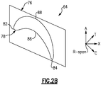
- An airfoil 78 extends in a radial direction R (shown in Fig. 2B ) from the platform 76 to a tip 80.
- the airfoil 78 provides leading and trailing edges 82, 84.
- the tip 80 is arranged adjacent to a blade outer air seal (not shown).
- FIGS 2A and 2B somewhat schematically illustrate an exterior airfoil surface 79 extending in a chord-wise direction C from a leading edge 82 to a trailing edge 84.
- the airfoil 78 is provided between pressure (typically concave) and suction (typically convex) walls 86, 88 in an airfoil thickness direction T, which is generally perpendicular to the chord-wise direction C.
- Multiple turbine blades 64 are arranged circumferentially in a circumferential direction A.
- the airfoil 78 extends from the platform 76 in the radial direction R, or spanwise, to the tip 80. It should be understood that the airfoil 78 may be utilized in other parts of the gas turbine engine 20, or in other gas turbine engines.
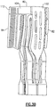
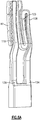
- the airfoil 78 is formed by investment casting a metallic alloy, such as a nickel alloy, or other material in a mold around an airfoil core 100, shown in Figures 3A-3B .
- the core 100 includes sections that correspond to portions of the cooling passages of the airfoil 78.
- Figure 3A shows the airfoil core 100 from the pressure side 86
- Figure 3B shows the airfoil core 100 from the suction side 88.
- the example airfoil core 100 includes a hybrid skin core 102, a tip flag core 104, a trailing edge core 106, a serpentine core 108, and a leading edge core 110.
- the airfoil core 100 may be fabricated using variety of manufacturing methods and used in conjunction with conventional investment casting processes. Core manufacturing methods may include, but are not limited to conventional core die tooling, injection molding, flexible tooling, fugitive core, lithographic tooling, and/or advanced additive manufacturing processes to directly fabricate integral ceramic cores for single and multi-walled cooling design concepts. Alternatively the airfoil cooling configuration may be directly fabricated using laser powder bed metal fusion additive manufacturing processes such as direct metal laser sintering (DMLS) or Selective Laser Sintering (SLS) methods.
- DMLS direct metal laser sintering
- SLS Selective Laser Sintering
- the core 100 is injection molded from a material that contains ceramic, silica or alumina aggregate and/or elements of a metal alloy material, for example.
- Solid structures define the core 100, which then produce void structures in the airfoil 78, after the core material is leached out of the metal airfoil as part of the investment casting process. These void structures make up a cooling passage network. Conversely, void structures of the core 100 produce solid structures in the airfoil 78.
- the core 100 may have several internal geometric features defining the internal core passages, cooling and heat transfer augmentation features, (i.e.; trip strips, crossovers, impingement rib features), and core producibility features, (i.e.; core printouts, chaplets, and core bumpers).
- the hybrid skin core 102 forms a hybrid skin cooling passage that extends radially and is provided in a thickness direction between the core cooling passages and the suction side 88 of the airfoil 78.
- the hybrid skin cooling passage provides double wall cooling, which improves local thermal cooling effectiveness of the turbine blade 64.
- film cooling holes may be drilled into the hybrid skin cooling passage to create a thin film boundary layer that protects the airfoil 78 from hot gases in the core flow path C.
- the hybrid skin cooling passage receives cooling fluid from a cooling source at the hybrid skin core inlet 130.
- the hybrid skin cooling passages located immediately adjacent to the airfoil suction side leading edge, are positioned to shield the leading edge feed cavity 110 as well as shield other cooling passages, such as a serpentine cooling passage on the pressure side formed by the serpentine core 108.
- This shielding reduces cooling air heat pickup of the airflow in the leading edge feed passage 110 and the serpentine cooling passages 108 by reducing the net heat flux emanating from the hot external airfoil wall along the suction side surfaces immediately adjacent to the leading edge feed passage 110 and the serpentine cooling passages 108.
- the reduction in cooling air temperature heat pickup enables a more effective thermal cooling design configuration by maximizing the potential temperature gradient between the external gas temperature and the colder internal cooling air temperature.
- the reduction in cooling air heat pickup also lowers the temperature of the local insulating boundary layer of the film cooling air, which thereby suppresses the local external heat flux and subsequent external hot wall metal temperatures.
- the shielding provided by the suction side hybrid skin core cavities 102 may allow for the elimination of some turbulator features.
- suction side internal trip strip features along the leading edge cooling passage 110 and serpentine cooling passages 108 immediately adjacent to the cold internal wall formed between the suction side hybrid skin cooling passages 102, and the leading edge cooling passage 110 and the serpentine cooling passages 108 may not be necessary.
- the additional convective heat transfer augmentation from trip strips or turbulators is not required along the internal cooling passage surfaces immediately adjacent to the cold internal wall. Therefore the overall pressure drop within the leading edge feed passage 110 and the serpentine cooling circuit 108 may be significantly reduced due to the lower friction losses associated with cooling passages having internal trip strips features present along only one of cooling passage surfaces immediately adjacent to the external airfoil wall pressure side 86.
- the tip flag core 104 forms a tip flag cooling passage extending from the hybrid skin core cooling passage 102 to the trailing edge 84 near the airfoil tip 80.
- the tip flag core 104 may be joined to or integrated with the hybrid skin core 102. This allows the cooling air from the hybrid skin passage to be reused to cool the tip flag cooling passage 104.
- the predominately axially flowing tip flag cooling passage 104 is arranged to maximize the internal convective heat transfer and provide uninterrupted access for optimization of tip film cooling holes, distributed along the pressure side tip surface, a pressure side tip shelf, and/or a tip squealer pocket.
- the ability to tailor the tip film cooling enables the local thermal cooling effectiveness of the airfoil tip 80 to be significantly improved by more efficiently reducing local tip operating metal temperatures and increasing tip durability oxidation and thermal mechanical fatigue (TMF) capability.
- TMF thermal mechanical fatigue
- the improvement in airfoil tip durability ensures that a minimum tip clearance between the airfoil tip 80 and the blade outer air seal is maintained throughout the life cycle of engine operation.
- the ability to minimize tip clearance between the airfoil tip 80 and a blade outer air seal is necessary to ensure the optimum performance characteristics of the turbine are retained.
- the trailing edge core 106 forms a trailing edge cooling passage extending radially between the pressure and suction sides 86, 88, and extending axially to the trailing edge 84. Cooling air enters the trailing edge cooling passage 106 via the trailing edge inlet 132.
- the hybrid skin core 102 is connected to the trailing edge core 106 and the tip flag core 104.
- the hybrid skin core 102 and trailing edge core 106 may be connected at the tip flag core 104 and/or at the inlets 130, 132 and/or at the exit of the tip flag 112 and the exit of the trailing edge 84, external to the airfoil 78.
- additional stock may be added to extend core material of the tip flag exit 112 and the exit of the trailing edge 84 in order to connect the two core passages at a location external to the airfoil 78 trailing edge geometry (shown in Fig. 7A ).
- This arrangement may help minimize the relative displacement between the tip flag 104 and trailing edge core 106.
- Joining the suction side hybrid skin core 102, the tip flag 104 and the trailing edge 84 during the core injection and manufacturing process may significantly improve casting process capability by improving internal and external wall control, relative core displacement, and core true position tolerance during wax injection and subsequent metal pour operations as part of the investment casting process.
- the serpentine core 108 forms a serpentine cooling passage arranged between the hybrid skin cooling passage 102 and the pressure side 86 of the airfoil 78.
- the example serpentine core 108 provides "up" passages 120, 122 fluidly joined by a “down" passage 124.
- Each of the passages 120, 122, 124 extends in a generally radial direction.
- cooling air flows forward. That is, the cooling air enters the serpentine core passage at an inlet 134, and flows upstream towards the leading edge 82.
- the serpentine cooling passage 108 may be co-flowing or counter-flowing, for example. At least one of the passages 120, 122, 124 is shielded by the hybrid skin cavity 102 on the suction side 88.
- At least one passage 120, 122, 124 extends into a pressure side tip shelf and/or a recessed tip squealer pocket.
- the passages 120, 122 are joined radially inward of the tip 80. This permits the serpentine core 108 to fit radially inward of the tip flag core 104.
- the tip turn is reduced in radial height such that the turn is recessed radially inward of the tip flag core 104, minimizing the overall pressure loss and cooling air heat pickup due to the reduced streamwise length of the serpentine cooling passage 108.
- the reduction in pressure loss may be further improved by incorporating trip strip or turbulator features 123 (shown schematically in Fig.
- the passages 120, 122, 124 may include pedestals, crossovers, and/or ribs, depending upon the particular core design.
- the last "up" passage 122 of the serpentine cooling passage 108 is designed to "print-out” along the airfoil tip 80 via a port 144, either within the pressure side tip shelf and/or within the tip squealer pocket.
- the "print-out" port 144 of the last “up” passage 122 of serpentine passage 108 may be used to purge residual ceramic core material contained within the cast airfoil after alloy metal pour and solidification.
- the port 144 is a purge feature that may be fabricated directly from core material during the core injection process.
- the last "up" passage 122 may comprise of a "solid rod” feature 140 (shown in Figures 7A-7B ) around which ceramic core material is injected.
- the solid rod feature 140 may be made of quartz, alumina, platinum, or any other high melt temperature material.
- the solid rod 140 enables improved wall control and positioning of the last "up" passage 122, while also providing a method to stabilize the serpentine 108 cooling circuit passages and/or core section 142 forming a "plenum-like" geometry feature.
- the port 144 is formed by the rod feature 140.
- the leading edge core 110 forms a leading edge cooling passage which purges cooling air at the leading edge 82.
- the cooling air is purged into a pressure side tip shelf.
- the leading edge cooling passage 110 is also shielded by the hybrid skin core passage 102, which reduces heat pickup to the leading edge cooling passage 110.
- a plurality of cavities 138 are arranged at the leading edge 82, and deliver film cooling to the leading edge 82. Cooling air enters the leading edge cooling passage 110 via the inlet 136.
- the arrangement of the hybrid skin passage 102 improves thermal cooling across the leading edge 82, which reduces the film cooling and improves durability of the airfoil 78.
- a solid rod feature 140 may also be integrated into the leading core 110 which forms the leading edge cooling passage 110 and serves a similar purpose as it pertains to serving as a conduit for leaching core material out of the cast airfoil 78. Additionally the solid rod feature 140 emanating from the leading core 110 may be combined and joined with another solid rod feature 140 emanating for the last "up" passage core 122. Each of the solid rod features 140 may be integrally “joined” by a common ceramic core "plenum-like" geometry feature 142 which extends radially outboard of the outer diameter of the airfoil tip 80, in which both solid rods 140 emanating from the leading edge core 110 and the serpentine core 108 are encapsulated. In this sense the two cores 110 and 108 are physically constrained in order to improve core stability and relative movement, thereby improving core manufacturing and casting process capability.
- Multi-walled blades are desirable in high performance turbines because of their effective use of cooling air, but such multi-walled blades require complex and expensive manufacturing techniques.
- One known technique includes forming multiple cores that must be individually assembled into a full core. This may result in increased tolerances between the cores, increased cost for multiple core dies, and increased time of assembly for multiple cores.
- Another known core manufacturing technique involves a fugitive core process which requires multiple wax inserts for the ceramic injection process, and typically slows the rate of production and is more expensive and complex.
- the disclosed core 100 permits simplified manufacturing of a multi-walled blade.
- the disclosed airfoil core 100 combines the suction side hybrid skin core 102 with the trailing edge core 106. These cores 102, 106 are connected at the trailing edge 84 via the tip flag 104 running from the skin core 102 to the trailing edge 84. The cores 102, 106 may also be connected at the root outside of the finished casting part. This combination of the hybrid skin core 102 and trailing edge core 106 allows the cores to be produced in a single die, reducing the die count. The combination also reduces the number of separate cores that need to be assembled into the final core 100. The connectivity reduces tolerances between the connected cores and provides better overall and relative core positioning control.
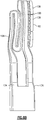
- a method of forming the disclosed core 100 includes forming the trailing edge core 106 and hybrid skin core 102 in a single die, as shown in Figure 5A-5B .
- the hybrid skin core 102 is connected to the trailing edge core 106 via the tip flag core 104.
- the skin core 102 may also be connected to the trailing edge core 106 at the root.
- the leading edge core 110 and serpentine core 108 are formed.
- the leading edge core 110 and serpentine core 108 may be formed in a single die, or may be formed separately and then assembled together.
- the cores may be formed by injection molding.
- each of the cores 102, 104, 106, 108, 110 are formed from a refractory metal core body material, silica, alumina, or another ceramic core body material.
- the hybrid skin core 102, tip flag core 104, and trailing edge core 106 are injection molded concurrently in a single die to form a contiguous first core portion.
- the leading edge core 110 and serpentine core 108 are injection molded concurrently in a single die to form a contiguous second core portion. In other embodiments, some of these components are injected separately.
- the first core portion and second core portion are assembled to form an airfoil core 100, or cores 102, 104, 106, 108, 110 are assembled together to form the airfoil core 100.
- additional structures are used to maintain the arrangement of the cores 102, 104, 106, 108, 110 in the airfoil core 100.
- a quartz or alumina rod 140 may extend from the serpentine core 108 or the leading edge core 110.
- a rod 140 may also be used in the trailing edge core 106 and tip flag core 104.
- a rod 140 may be used to join any two adjacent cores 102, 104, 106, 108, 110.
- Such rods 140 provide additional stabilization between cores, preventing relative movement during the manufacturing process.
- the airfoil 78 is formed about the airfoil core 100.
- the airfoil core 100 is placed into a wax tool, which is used to create a wax pattern of the exterior shape of the airfoil 78.
- This wax tool may form the airfoil surface 79, platform 76, and, root 74 (shown in Figure 2A ).
- these wax patterns are placed into an array, and ceramic slurry and particles are poured over the wax patterns to create a mold shell. Finally, the wax is melted out to leave a void in the mold shell, which is later filled with a molten metallic material, for example.
- the core arrangement may also provide better control of the core portions.
- the disclosed core 100 enables tighter control of the rib between the trailing edge core and tip flag core, and better positional control of the hybrid skin core.
- the quantity, size, orientation, and location will be dictated by the necessity to increase the local thermal cooling effectiveness and achieve the necessary thermal performance required to mitigate hot section part cooling airflow requirements, as well as, meet part and module level durability life, stage efficiency, module, and overall engine cycle performance and mission weight fuel burn requirements.
- core fabrication methods utilizing fugitive cores, injection molded, and additive manufacturing methods may be implemented to provide even greater robustness and flexibility in the manufacturing of complex multi-core / multi-wall design configurations similar to the final core 100.
- These advanced core manufacturing processes eliminate the requirement and need for multiple complex multi-pull and/or single pull core die tooling and core assembly.
- geometric core passage and core passage cooling design geometry features i.e.; trip strips, pin fins, pedestals, cross overs, impingement ribs, etc.
- Core passage and cooling feature geometries constrained to specific shapes, sizes, and orientations, due to core manufacturing limitations associated with core die tooling such as back-lock, die pull orientations, and core finishing processes may be significantly reduced and/or eliminated allowing more cooling design flexibility and optimization of integral multi-wall core cooling configurations.
Landscapes
- Engineering & Computer Science (AREA)
- Mechanical Engineering (AREA)
- General Engineering & Computer Science (AREA)
- Molds, Cores, And Manufacturing Methods Thereof (AREA)
- Turbine Rotor Nozzle Sealing (AREA)
Applications Claiming Priority (3)
| Application Number | Priority Date | Filing Date | Title |
|---|---|---|---|
| US201862739657P | 2018-10-01 | 2018-10-01 | |
| US201862741322P | 2018-10-04 | 2018-10-04 | |
| US16/202,483 US11015457B2 (en) | 2018-10-01 | 2018-11-28 | Multi-walled airfoil core |
Publications (2)
| Publication Number | Publication Date |
|---|---|
| EP3633150A1 true EP3633150A1 (fr) | 2020-04-08 |
| EP3633150B1 EP3633150B1 (fr) | 2021-12-01 |
Family
ID=68109233
Family Applications (1)
| Application Number | Title | Priority Date | Filing Date |
|---|---|---|---|
| EP19200847.2A Active EP3633150B1 (fr) | 2018-10-01 | 2019-10-01 | Procédé de fabrication d´une aube et aube correspondante |
Country Status (2)
| Country | Link |
|---|---|
| US (2) | US11015457B2 (fr) |
| EP (1) | EP3633150B1 (fr) |
Families Citing this family (4)
| Publication number | Priority date | Publication date | Assignee | Title |
|---|---|---|---|---|
| US11015457B2 (en) * | 2018-10-01 | 2021-05-25 | Raytheon Technologies Corporation | Multi-walled airfoil core |
| CN112439876A (zh) * | 2020-11-23 | 2021-03-05 | 东方电气集团东方汽轮机有限公司 | 一种燃机空心叶片静叶出气边制造方法 |
| US11913353B2 (en) | 2021-08-06 | 2024-02-27 | Rtx Corporation | Airfoil tip arrangement for gas turbine engine |
| US11920496B1 (en) * | 2022-11-10 | 2024-03-05 | Doosan Enerbility Co., Ltd. | Airfoil, and turbine blade and gas turbine including the same |
Citations (5)
| Publication number | Priority date | Publication date | Assignee | Title |
|---|---|---|---|---|
| WO2015181488A1 (fr) * | 2014-05-28 | 2015-12-03 | Snecma | Aube de turbine a refroidissement optimise au niveau de son bord de fuite comprenant des conduits amont et aval et des cavités latérales internes |
| FR3041989A1 (fr) * | 2015-10-06 | 2017-04-07 | Snecma | Aube comportant un bord de fuite comprenant trois regions de refroidissement distinctes |
| US20180050386A1 (en) * | 2016-08-18 | 2018-02-22 | General Electric Company | Method and assembly for a multiple component core assembly |
| EP3330487A1 (fr) * | 2016-12-05 | 2018-06-06 | United Technologies Corporation | Cavités hybrides de bord d'attaque et noyaux pour aubes de moteur de turbine à gaz |
| US20180156045A1 (en) * | 2016-12-05 | 2018-06-07 | United Technologies Corporation | Aft flowing serpentine cavities and cores for airfoils of gas turbine engines |
Family Cites Families (12)
| Publication number | Priority date | Publication date | Assignee | Title |
|---|---|---|---|---|
| US4627480A (en) | 1983-11-07 | 1986-12-09 | General Electric Company | Angled turbulence promoter |
| US5599166A (en) | 1994-11-01 | 1997-02-04 | United Technologies Corporation | Core for fabrication of gas turbine engine airfoils |
| US6637500B2 (en) | 2001-10-24 | 2003-10-28 | United Technologies Corporation | Cores for use in precision investment casting |
| US6974308B2 (en) | 2001-11-14 | 2005-12-13 | Honeywell International, Inc. | High effectiveness cooled turbine vane or blade |
| US6929054B2 (en) | 2003-12-19 | 2005-08-16 | United Technologies Corporation | Investment casting cores |
| US7625178B2 (en) | 2006-08-30 | 2009-12-01 | Honeywell International Inc. | High effectiveness cooled turbine blade |
| US8292581B2 (en) | 2008-01-09 | 2012-10-23 | Honeywell International Inc. | Air cooled turbine blades and methods of manufacturing |
| US9486854B2 (en) | 2012-09-10 | 2016-11-08 | United Technologies Corporation | Ceramic and refractory metal core assembly |
| FR3021697B1 (fr) | 2014-05-28 | 2021-09-17 | Snecma | Aube de turbine a refroidissement optimise |
| FR3048374B1 (fr) | 2016-03-01 | 2018-04-06 | Snecma | Noyau pour le moulage d'une aube ayant des cavites superposees et comprenant un conduit de depoussierage traversant une cavite de part en part |
| US10989056B2 (en) | 2016-12-05 | 2021-04-27 | Raytheon Technologies Corporation | Integrated squealer pocket tip and tip shelf with hybrid and tip flag core |
| US11015457B2 (en) * | 2018-10-01 | 2021-05-25 | Raytheon Technologies Corporation | Multi-walled airfoil core |
-
2018
- 2018-11-28 US US16/202,483 patent/US11015457B2/en active Active
-
2019
- 2019-10-01 EP EP19200847.2A patent/EP3633150B1/fr active Active
-
2021
- 2021-05-17 US US17/322,211 patent/US11434768B2/en active Active
Patent Citations (5)
| Publication number | Priority date | Publication date | Assignee | Title |
|---|---|---|---|---|
| WO2015181488A1 (fr) * | 2014-05-28 | 2015-12-03 | Snecma | Aube de turbine a refroidissement optimise au niveau de son bord de fuite comprenant des conduits amont et aval et des cavités latérales internes |
| FR3041989A1 (fr) * | 2015-10-06 | 2017-04-07 | Snecma | Aube comportant un bord de fuite comprenant trois regions de refroidissement distinctes |
| US20180050386A1 (en) * | 2016-08-18 | 2018-02-22 | General Electric Company | Method and assembly for a multiple component core assembly |
| EP3330487A1 (fr) * | 2016-12-05 | 2018-06-06 | United Technologies Corporation | Cavités hybrides de bord d'attaque et noyaux pour aubes de moteur de turbine à gaz |
| US20180156045A1 (en) * | 2016-12-05 | 2018-06-07 | United Technologies Corporation | Aft flowing serpentine cavities and cores for airfoils of gas turbine engines |
Also Published As
| Publication number | Publication date |
|---|---|
| US11434768B2 (en) | 2022-09-06 |
| US11015457B2 (en) | 2021-05-25 |
| EP3633150B1 (fr) | 2021-12-01 |
| US20210277785A1 (en) | 2021-09-09 |
| US20200102841A1 (en) | 2020-04-02 |
Similar Documents
| Publication | Publication Date | Title |
|---|---|---|
| US11951532B2 (en) | Additively manufactured core | |
| US11434768B2 (en) | Multi-walled airfoil core | |
| EP3019704B1 (fr) | Refroidissement de composants pour moteur à turbine à gaz à réapprovisionnement de passage de refroidissement | |
| EP3556999B1 (fr) | Configuration de refroidissement de surface portante à double paroi pour moteur à turbine à gaz | |
| US11014145B2 (en) | Core assembly including studded spacer | |
| EP3508697B1 (fr) | Configuration de refroidissement de plate-forme et d'aube de turbine de moteur à turbine à gaz comportant un réapprovisionnement du noyau principal | |
| EP3495617B1 (fr) | Profil aérodynamique avec des passages de refroidissement internes | |
| EP3508696B1 (fr) | Configuration de refroidissement de plate-forme et d'aube de moteur à turbine à gaz | |
| EP3498979B1 (fr) | Aube refroidie | |
| US20210363924A1 (en) | Hourglass airfoil cooling configuration | |
| EP3495615B1 (fr) | Profil aérodynamique avec des passages de refroidissement internes | |
| EP3495616B1 (fr) | Profil aérodynamique avec des passages de refroidissement internes | |
| US20200149416A1 (en) | Airfoil with skincore passage resupply | |
| US20230250725A1 (en) | Cooling arrangement for gas turbine engine component | |
| EP3495619B1 (fr) | Profil aérodynamique avec des passages de refroidissement internes | |
| EP3495620B1 (fr) | Profil aérodynamique avec des passages de refroidissement internes |
Legal Events
| Date | Code | Title | Description |
|---|---|---|---|
| PUAI | Public reference made under article 153(3) epc to a published international application that has entered the european phase |
Free format text: ORIGINAL CODE: 0009012 |
|
| STAA | Information on the status of an ep patent application or granted ep patent |
Free format text: STATUS: THE APPLICATION HAS BEEN PUBLISHED |
|
| AK | Designated contracting states |
Kind code of ref document: A1 Designated state(s): AL AT BE BG CH CY CZ DE DK EE ES FI FR GB GR HR HU IE IS IT LI LT LU LV MC MK MT NL NO PL PT RO RS SE SI SK SM TR |
|
| AX | Request for extension of the european patent |
Extension state: BA ME |
|
| STAA | Information on the status of an ep patent application or granted ep patent |
Free format text: STATUS: REQUEST FOR EXAMINATION WAS MADE |
|
| 17P | Request for examination filed |
Effective date: 20201001 |
|
| RBV | Designated contracting states (corrected) |
Designated state(s): AL AT BE BG CH CY CZ DE DK EE ES FI FR GB GR HR HU IE IS IT LI LT LU LV MC MK MT NL NO PL PT RO RS SE SI SK SM TR |
|
| RAP1 | Party data changed (applicant data changed or rights of an application transferred) |
Owner name: RAYTHEON TECHNOLOGIES CORPORATION |
|
| GRAP | Despatch of communication of intention to grant a patent |
Free format text: ORIGINAL CODE: EPIDOSNIGR1 |
|
| STAA | Information on the status of an ep patent application or granted ep patent |
Free format text: STATUS: GRANT OF PATENT IS INTENDED |
|
| INTG | Intention to grant announced |
Effective date: 20210526 |
|
| GRAS | Grant fee paid |
Free format text: ORIGINAL CODE: EPIDOSNIGR3 |
|
| GRAA | (expected) grant |
Free format text: ORIGINAL CODE: 0009210 |
|
| STAA | Information on the status of an ep patent application or granted ep patent |
Free format text: STATUS: THE PATENT HAS BEEN GRANTED |
|
| AK | Designated contracting states |
Kind code of ref document: B1 Designated state(s): AL AT BE BG CH CY CZ DE DK EE ES FI FR GB GR HR HU IE IS IT LI LT LU LV MC MK MT NL NO PL PT RO RS SE SI SK SM TR |
|
| REG | Reference to a national code |
Ref country code: GB Ref legal event code: FG4D |
|
| REG | Reference to a national code |
Ref country code: AT Ref legal event code: REF Ref document number: 1451943 Country of ref document: AT Kind code of ref document: T Effective date: 20211215 Ref country code: CH Ref legal event code: EP |
|
| REG | Reference to a national code |
Ref country code: IE Ref legal event code: FG4D |
|
| REG | Reference to a national code |
Ref country code: DE Ref legal event code: R096 Ref document number: 602019009677 Country of ref document: DE |
|
| REG | Reference to a national code |
Ref country code: LT Ref legal event code: MG9D |
|
| REG | Reference to a national code |
Ref country code: NL Ref legal event code: MP Effective date: 20211201 |
|
| REG | Reference to a national code |
Ref country code: AT Ref legal event code: MK05 Ref document number: 1451943 Country of ref document: AT Kind code of ref document: T Effective date: 20211201 |
|
| PG25 | Lapsed in a contracting state [announced via postgrant information from national office to epo] |
Ref country code: RS Free format text: LAPSE BECAUSE OF FAILURE TO SUBMIT A TRANSLATION OF THE DESCRIPTION OR TO PAY THE FEE WITHIN THE PRESCRIBED TIME-LIMIT Effective date: 20211201 Ref country code: LT Free format text: LAPSE BECAUSE OF FAILURE TO SUBMIT A TRANSLATION OF THE DESCRIPTION OR TO PAY THE FEE WITHIN THE PRESCRIBED TIME-LIMIT Effective date: 20211201 Ref country code: FI Free format text: LAPSE BECAUSE OF FAILURE TO SUBMIT A TRANSLATION OF THE DESCRIPTION OR TO PAY THE FEE WITHIN THE PRESCRIBED TIME-LIMIT Effective date: 20211201 Ref country code: BG Free format text: LAPSE BECAUSE OF FAILURE TO SUBMIT A TRANSLATION OF THE DESCRIPTION OR TO PAY THE FEE WITHIN THE PRESCRIBED TIME-LIMIT Effective date: 20220301 Ref country code: AT Free format text: LAPSE BECAUSE OF FAILURE TO SUBMIT A TRANSLATION OF THE DESCRIPTION OR TO PAY THE FEE WITHIN THE PRESCRIBED TIME-LIMIT Effective date: 20211201 |
|
| PG25 | Lapsed in a contracting state [announced via postgrant information from national office to epo] |
Ref country code: SE Free format text: LAPSE BECAUSE OF FAILURE TO SUBMIT A TRANSLATION OF THE DESCRIPTION OR TO PAY THE FEE WITHIN THE PRESCRIBED TIME-LIMIT Effective date: 20211201 Ref country code: PL Free format text: LAPSE BECAUSE OF FAILURE TO SUBMIT A TRANSLATION OF THE DESCRIPTION OR TO PAY THE FEE WITHIN THE PRESCRIBED TIME-LIMIT Effective date: 20211201 Ref country code: NO Free format text: LAPSE BECAUSE OF FAILURE TO SUBMIT A TRANSLATION OF THE DESCRIPTION OR TO PAY THE FEE WITHIN THE PRESCRIBED TIME-LIMIT Effective date: 20220301 Ref country code: LV Free format text: LAPSE BECAUSE OF FAILURE TO SUBMIT A TRANSLATION OF THE DESCRIPTION OR TO PAY THE FEE WITHIN THE PRESCRIBED TIME-LIMIT Effective date: 20211201 Ref country code: HR Free format text: LAPSE BECAUSE OF FAILURE TO SUBMIT A TRANSLATION OF THE DESCRIPTION OR TO PAY THE FEE WITHIN THE PRESCRIBED TIME-LIMIT Effective date: 20211201 Ref country code: GR Free format text: LAPSE BECAUSE OF FAILURE TO SUBMIT A TRANSLATION OF THE DESCRIPTION OR TO PAY THE FEE WITHIN THE PRESCRIBED TIME-LIMIT Effective date: 20220302 Ref country code: ES Free format text: LAPSE BECAUSE OF FAILURE TO SUBMIT A TRANSLATION OF THE DESCRIPTION OR TO PAY THE FEE WITHIN THE PRESCRIBED TIME-LIMIT Effective date: 20211201 |
|
| PG25 | Lapsed in a contracting state [announced via postgrant information from national office to epo] |
Ref country code: NL Free format text: LAPSE BECAUSE OF FAILURE TO SUBMIT A TRANSLATION OF THE DESCRIPTION OR TO PAY THE FEE WITHIN THE PRESCRIBED TIME-LIMIT Effective date: 20211201 |
|
| PG25 | Lapsed in a contracting state [announced via postgrant information from national office to epo] |
Ref country code: SM Free format text: LAPSE BECAUSE OF FAILURE TO SUBMIT A TRANSLATION OF THE DESCRIPTION OR TO PAY THE FEE WITHIN THE PRESCRIBED TIME-LIMIT Effective date: 20211201 Ref country code: SK Free format text: LAPSE BECAUSE OF FAILURE TO SUBMIT A TRANSLATION OF THE DESCRIPTION OR TO PAY THE FEE WITHIN THE PRESCRIBED TIME-LIMIT Effective date: 20211201 Ref country code: RO Free format text: LAPSE BECAUSE OF FAILURE TO SUBMIT A TRANSLATION OF THE DESCRIPTION OR TO PAY THE FEE WITHIN THE PRESCRIBED TIME-LIMIT Effective date: 20211201 Ref country code: PT Free format text: LAPSE BECAUSE OF FAILURE TO SUBMIT A TRANSLATION OF THE DESCRIPTION OR TO PAY THE FEE WITHIN THE PRESCRIBED TIME-LIMIT Effective date: 20220401 Ref country code: EE Free format text: LAPSE BECAUSE OF FAILURE TO SUBMIT A TRANSLATION OF THE DESCRIPTION OR TO PAY THE FEE WITHIN THE PRESCRIBED TIME-LIMIT Effective date: 20211201 Ref country code: CZ Free format text: LAPSE BECAUSE OF FAILURE TO SUBMIT A TRANSLATION OF THE DESCRIPTION OR TO PAY THE FEE WITHIN THE PRESCRIBED TIME-LIMIT Effective date: 20211201 |
|
| REG | Reference to a national code |
Ref country code: DE Ref legal event code: R026 Ref document number: 602019009677 Country of ref document: DE |
|
| PLBI | Opposition filed |
Free format text: ORIGINAL CODE: 0009260 |
|
| PLAB | Opposition data, opponent's data or that of the opponent's representative modified |
Free format text: ORIGINAL CODE: 0009299OPPO |
|
| PLAX | Notice of opposition and request to file observation + time limit sent |
Free format text: ORIGINAL CODE: EPIDOSNOBS2 |
|
| PG25 | Lapsed in a contracting state [announced via postgrant information from national office to epo] |
Ref country code: IS Free format text: LAPSE BECAUSE OF FAILURE TO SUBMIT A TRANSLATION OF THE DESCRIPTION OR TO PAY THE FEE WITHIN THE PRESCRIBED TIME-LIMIT Effective date: 20220401 |
|
| 26 | Opposition filed |
Opponent name: SAFRAN AIRCRAFT ENGINES Effective date: 20220831 |
|
| R26 | Opposition filed (corrected) |
Opponent name: SAFRAN AIRCRAFT ENGINES Effective date: 20220831 |
|
| PG25 | Lapsed in a contracting state [announced via postgrant information from national office to epo] |
Ref country code: DK Free format text: LAPSE BECAUSE OF FAILURE TO SUBMIT A TRANSLATION OF THE DESCRIPTION OR TO PAY THE FEE WITHIN THE PRESCRIBED TIME-LIMIT Effective date: 20211201 Ref country code: AL Free format text: LAPSE BECAUSE OF FAILURE TO SUBMIT A TRANSLATION OF THE DESCRIPTION OR TO PAY THE FEE WITHIN THE PRESCRIBED TIME-LIMIT Effective date: 20211201 |
|
| PG25 | Lapsed in a contracting state [announced via postgrant information from national office to epo] |
Ref country code: SI Free format text: LAPSE BECAUSE OF FAILURE TO SUBMIT A TRANSLATION OF THE DESCRIPTION OR TO PAY THE FEE WITHIN THE PRESCRIBED TIME-LIMIT Effective date: 20211201 |
|
| PLBB | Reply of patent proprietor to notice(s) of opposition received |
Free format text: ORIGINAL CODE: EPIDOSNOBS3 |
|
| PG25 | Lapsed in a contracting state [announced via postgrant information from national office to epo] |
Ref country code: MC Free format text: LAPSE BECAUSE OF FAILURE TO SUBMIT A TRANSLATION OF THE DESCRIPTION OR TO PAY THE FEE WITHIN THE PRESCRIBED TIME-LIMIT Effective date: 20211201 Ref country code: IT Free format text: LAPSE BECAUSE OF FAILURE TO SUBMIT A TRANSLATION OF THE DESCRIPTION OR TO PAY THE FEE WITHIN THE PRESCRIBED TIME-LIMIT Effective date: 20211201 |
|
| REG | Reference to a national code |
Ref country code: CH Ref legal event code: PL |
|
| REG | Reference to a national code |
Ref country code: BE Ref legal event code: MM Effective date: 20221031 |
|
| P01 | Opt-out of the competence of the unified patent court (upc) registered |
Effective date: 20230521 |
|
| PG25 | Lapsed in a contracting state [announced via postgrant information from national office to epo] |
Ref country code: LU Free format text: LAPSE BECAUSE OF NON-PAYMENT OF DUE FEES Effective date: 20221001 |
|
| PG25 | Lapsed in a contracting state [announced via postgrant information from national office to epo] |
Ref country code: LI Free format text: LAPSE BECAUSE OF NON-PAYMENT OF DUE FEES Effective date: 20221031 Ref country code: CH Free format text: LAPSE BECAUSE OF NON-PAYMENT OF DUE FEES Effective date: 20221031 |
|
| PG25 | Lapsed in a contracting state [announced via postgrant information from national office to epo] |
Ref country code: BE Free format text: LAPSE BECAUSE OF NON-PAYMENT OF DUE FEES Effective date: 20221031 |
|
| PG25 | Lapsed in a contracting state [announced via postgrant information from national office to epo] |
Ref country code: IE Free format text: LAPSE BECAUSE OF NON-PAYMENT OF DUE FEES Effective date: 20221001 |
|
| PGFP | Annual fee paid to national office [announced via postgrant information from national office to epo] |
Ref country code: GB Payment date: 20230920 Year of fee payment: 5 |
|
| RAP4 | Party data changed (patent owner data changed or rights of a patent transferred) |
Owner name: RTX CORPORATION |
|
| PGFP | Annual fee paid to national office [announced via postgrant information from national office to epo] |
Ref country code: FR Payment date: 20230920 Year of fee payment: 5 |
|
| PGFP | Annual fee paid to national office [announced via postgrant information from national office to epo] |
Ref country code: DE Payment date: 20230920 Year of fee payment: 5 |
|
| REG | Reference to a national code |
Ref country code: CH Ref legal event code: PK Free format text: TITEL |
|
| PG25 | Lapsed in a contracting state [announced via postgrant information from national office to epo] |
Ref country code: HU Free format text: LAPSE BECAUSE OF FAILURE TO SUBMIT A TRANSLATION OF THE DESCRIPTION OR TO PAY THE FEE WITHIN THE PRESCRIBED TIME-LIMIT; INVALID AB INITIO Effective date: 20191001 |
|
| PG25 | Lapsed in a contracting state [announced via postgrant information from national office to epo] |
Ref country code: CY Free format text: LAPSE BECAUSE OF FAILURE TO SUBMIT A TRANSLATION OF THE DESCRIPTION OR TO PAY THE FEE WITHIN THE PRESCRIBED TIME-LIMIT Effective date: 20211201 |