EP3633087A1 - Bobbin replacement device for pot spinning machine - Google Patents
Bobbin replacement device for pot spinning machine Download PDFInfo
- Publication number
- EP3633087A1 EP3633087A1 EP19197141.5A EP19197141A EP3633087A1 EP 3633087 A1 EP3633087 A1 EP 3633087A1 EP 19197141 A EP19197141 A EP 19197141A EP 3633087 A1 EP3633087 A1 EP 3633087A1
- Authority
- EP
- European Patent Office
- Prior art keywords
- bobbin
- lid
- pot
- spinning machine
- fixed cover
- Prior art date
- Legal status (The legal status is an assumption and is not a legal conclusion. Google has not performed a legal analysis and makes no representation as to the accuracy of the status listed.)
- Granted
Links
Images






Classifications
-
- D—TEXTILES; PAPER
- D01—NATURAL OR MAN-MADE THREADS OR FIBRES; SPINNING
- D01H—SPINNING OR TWISTING
- D01H1/00—Spinning or twisting machines in which the product is wound-up continuously
- D01H1/08—Spinning or twisting machines in which the product is wound-up continuously cup, pot or disc type, in which annular masses of yarn are formed by centrifugal action
-
- D—TEXTILES; PAPER
- D01—NATURAL OR MAN-MADE THREADS OR FIBRES; SPINNING
- D01H—SPINNING OR TWISTING
- D01H9/00—Arrangements for replacing or removing bobbins, cores, receptacles, or completed packages at paying-out or take-up stations ; Combination of spinning-winding machine
- D01H9/02—Arrangements for replacing or removing bobbins, cores, receptacles, or completed packages at paying-out or take-up stations ; Combination of spinning-winding machine for removing completed take-up packages and replacing by bobbins, cores, or receptacles at take-up stations; Transferring material between adjacent full and empty take-up elements
- D01H9/04—Doffing arrangements integral with spinning or twisting machines
Definitions
- the present disclosure relates to a bobbin replacement device for a pot spinning machine.
- a pot spinning machine forms a cake by depositing yarn, which has been delivered into a pot through a yarn introduction pipe, against an inside wall of the pot by a centrifugal force involved in fast rotation of the pot, and the pot spinning machine rewinds the yarn onto a bobbin in the pot. If the pot is rotated with an opening of the pot opened, windage loss in the pot is increased by air that flows into the pot through the opening and air that flows out of the pot through the opening during the rotation of the pot. Furthermore, the air that flows into the pot may bring cotton fly into the pot, and the cotton fly mixed with the yarn degrades the quality of the yarn. In addition, the fast rotation of the pot with the pot exposed may reduce the safety around the pot.
- Known pot spinning machines include a fixed cover that surrounds the pot and a lid that closes an opening of the fixed cover, in order to reduce the windage loss in the pot.
- the pot has a downward opening
- the fixed cover surrounding the pot has an opening that is closed by an openable lid (for example, refer to a pot spinning machine disclosed in Japanese Patent Application Publication No. 08-060430 ).
- the opening of the fixed cover opens downward as well as the opening of the pot, and the downward opening of the fixed cover is closed by the lid in order to reduce windage loss in the pot.
- the present disclosure has been made to solve the above-described problem and is directed to providing a bobbin replacement device for a pot spinning machine in which a downward opening of a fixed cover is opened and closed with a lid without mounting of a drive source for operating the lid to the pot spinning machine.
- a bobbin replacement device for a pot spinning machine.
- the pot spinning machine includes a pot having an opening that opens downward, a fixed cover surrounding the pot and having an opening that opens downward, and a bobbin support part supporting a bobbin below the pot.
- the bobbin replacement device is configured to replace the full bobbin with an empty bobbin.
- the bobbin replacement device for the pot spinning machine includes a drive mechanism for replacing the bobbin, a movable portion, and a lid.
- the movable portion includes a bobbin holder that holds the bobbin at replacement of the bobbin, and is moved in a predetermined direction by the drive mechanism.
- the lid is attached to the movable portion such that the lid is moved together with the movable portion.
- the lid is placed at a close position to close the opening of the fixed cover and placed at an open position to open the opening of the fixed cover according to the movement of the movable portion by the drive mechanism.
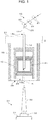
- FIG. 1 is a schematic view illustrating an exemplary configuration of a pot spinning machine according to an embodiment of the present disclosure.
- a pot spinning machine 1 includes a drafting device 10, a yarn suction pipe 12, a yarn introduction pipe 14, a pot 16, a fixed cover 18, and a bobbin support part 20. These elements cooperate to form a single spindle that represents a unit of spinning.
- the pot spinning machine 1 generally includes a plurality of spindles, but the following will focus on one of the spindles.
- the drafting device 10 is a device that draws out a yarn material.
- the drafting device 10 includes multiple pairs of rollers, such as a pair of back rollers 21, a pair of middle rollers 22, and a pair of front rollers 23.
- the pair of back rollers 21, the pair of middle rollers 22, and the pair of front rollers 23 are arranged in this order from upstream to downstream of a roving feed direction.
- the pairs of rollers 21, 22, 23 are rotated by a drafting-device driving section that is not illustrated.
- a drafting-device driving section that is not illustrated.
- the rotational speeds of the pairs of rollers 21, 22, 23 are compared by revolutions per minute (rpm)
- the rpm of the pair of middle rollers 22 is greater than the rpm of the pair of back rollers 21, and the rpm of the pair of front rollers 23 is greater than the rpm of the pair of middle rollers 22.
- the rpm of the pairs of rollers 21, 22, 23 are different from each other, and the drafting device 10 thinly draws out the yarn material by using the difference in rpm among the pairs of rollers 21, 22, 23, that is, the difference in rotational speed among the pairs of rollers 21, 22, 23.
- the yarn suction pipe 12 draws a yarn 25 supplied by the drafting device 10, and feeds the drawn yarn 25 into the yarn introduction pipe 14.
- the yarn suction pipe 12 uses air swirl flow to introduce the yarn 25, which has been drawn out by the drafting device 10.
- the yarn introduction pipe 14 introduces the yarn 25, which has been fed from the drafting device 10 through the yarn suction pipe 12, into the pot 16.
- the yarn introduction pipe 14 has a long thin tube-like shape.
- the yarn introduction pipe 14 has a circular cross section in a direction perpendicular to a longitudinal direction of the yarn introduction pipe 14.
- the yarn introduction pipe 14 is disposed downstream of the drafting device 10, and is coaxial with the yarn suction pipe 12 and the pot 16.
- the yarn introduction pipe 14 penetrates through an upper portion of the pot 16 to be inserted into the pot 16.
- the yarn introduction pipe 14 has a yarn inlet 14a and a yarn outlet 14b at a top end and a bottom end of the yarn introduction pipe 14, respectively.
- the yarn 25 fed into the yarn introduction pipe 14 through the yarn inlet 14a is discharged from the yarn outlet 14b of the yarn introduction pipe 14.
- the pot 16 is used for formation of a cake 24 and yarn rewinding.
- the cake 24 is a deposit of yarn that is formed on an inside wall of the pot 16 by operation of the yarn introduction pipe 14, which will be described later.
- the pot 16 has a cylindrical shape.
- the pot 16 is rotatable with respect to a central axis K of the pot 16.
- the central axis K of the pot 16 is parallel to a vertical direction. Accordingly, one side of the pot 16 is an upper side, and the other side is a lower side in the central axis K direction.
- the pot 16 has an opening 26 at a bottom end of the pot 16.
- the opening 26 of the pot 16 has a diameter equal to an inner diameter of the pot 16, and the opening 26 opens downward.
- the fixed cover 18 is disposed surrounding the pot 16.
- the fixed cover 18 is fixed to a fixing portion 27.
- the fixed cover 18 has a cylindrical shape, and has a diameter greater than that of the pot 16.
- the fixed cover 18 is coaxial with the pot 16.
- the fixed cover 18 has, at a top end of the fixed cover 18, an opening that is closed by the fixing portion 27.
- the fixed cover 18 has an opening 28 at a bottom end of the fixed cover 18.
- the opening 28 of the fixed cover 18 has a diameter equal to an inner diameter of the fixed cover 18, and the opening 28 opens downward.
- the opening 28 of the fixed cover 18 is disposed below the opening 26 of the pot 16.
- the bobbin support part 20 supports a bobbin 30 below the pot 16.
- the bobbin support part 20 includes an elevating rail 31 and a bobbin support member 32.
- the elevating rail 31 is configured to move up and down.
- the bobbin support member 32 is attached to the elevating rail 31.
- the bobbin support member 32 is a portion of the bobbin support part 20 to which the bobbin 30 is attachable.
- the bobbin support member 32 is coaxial with the yarn introduction pipe 14 and the pot 16 such that the bobbin support member 32 faces the yarn introduction pipe 14 on the central axis K of the pot 16. Accordingly, the bobbin 30 faces the yarn introduction pipe 14 on the central axis K of the pot 16 in a state where the bobbin 30 is attached to the bobbin support member 32.
- the bobbin 30 is tapered such that an outer diameter of the bobbin 30 changes sequentially from one end to the other end of the bobbin 30 in a direction of a central axis of the bobbin 30.
- the bobbin 30 is supported by the bobbin support member 32 such that the bobbin 30 stands on the bobbin support member 32 vertically.
- the outer diameter of the bobbin 30 is smaller than the smallest diameter of the cake 24 formed on the inside wall of the pot 16. This configuration prevents the bobbin 30 from contacting the cake 24 when the bobbin 30 is inserted into the pot 16 through the opening 26 of the pot 16.
- the drafting device 10 draws out the yarn material, such as roving.
- the yarn 25, which has been drawn out by the drafting device 10, is drawn into the yarn suction pipe 12 by air swirl flow or the like, and fed into the yarn introduction pipe 14 through the yarn inlet 14a.
- the yarn 25 fed into the yarn introduction pipe 14 is discharged through the yarn outlet 14b of the yarn introduction pipe 14.
- the pot 16 is rotated at a predetermined rotational speed.
- the fixed cover 18 is stationary regardless of the rotation of the pot 16.
- the yarn 25 discharged from the yarn outlet 14b of the yarn introduction pipe 14 as described above is pressed onto the inside wall of the pot 16 by centrifugal force generated by the rotation of the pot 16.
- the yarn 25 discharged from the yarn outlet 14b of the yarn introduction pipe 14 is twisted by the rotation of the pot 16 and wound onto the inside wall of the pot 16.
- the yarn introduction pipe 14 displaces its position relatively downward while reciprocating at predetermined intervals in an up-and-down direction. Accordingly, the yarn 25 is wound onto the inside wall of the pot 16 while displacing its winding position, so that the cake 24 is formed on the inside wall of the pot 16.
- the elevating rail 31 moves up to insert the bobbin 30 into the pot 16 while the pot 16 is rotating. Then, the yarn of the cake 24 is rewound onto the bobbin 30.
- the yarn is rewound onto the bobbin 30, for example, by a yarn disentangling member (not illustrated) contacting an end of the yarn of the cake 24.
- the elevating rail 31 moves down to remove the bobbin 30 from the pot 16.
- the bobbin 30 removed from the pot 16 is a full bobbin onto which a predetermined amount of the yarn has been rewound.
- FIG. 2 is a schematic front view illustrating an exemplary configuration of a bobbin replacement device of the pot spinning machine according to the embodiment of the present disclosure
- FIG. 3 is a schematic side view illustrating the same.
- a bobbin replacement device 40 is a device configured to replace the bobbin 30, which is supported by the bobbin support part 20 and is a full bobbin, with an empty bobbin.
- the bobbin replacement device 40 according to this embodiment is a simultaneous bobbin replacement device that is configured to simultaneously perform a bobbin replacement for all spindles of the pot spinning machine 1.
- the bobbin replacement device 40 includes a bobbin holder 42 ( FIG. 3 ) that holds the bobbin 30 at the replacement of the bobbin 30, a doffing bar 44 that supports the bobbin holder 42, a pantograph mechanism 46 that elevates the doffing bar 44, and a tilt mechanism 48 that tilts the pantograph mechanism 46.
- the bobbin holder 42 and the doffing bar 44 cooperate to serve as a movable portion of the present disclosure, in other words, the movable portion of the present disclosure includes the bobbin holder 42.
- the pantograph mechanism 46 and the tilt mechanism 48 cooperate to serve as a drive mechanism of the present disclosure for replacing the bobbin.
- the bobbin holder 42 may be, for example, a bobbin holder disclosed in Japanese Patent Application Publication No. 09-087931 .
- the bobbin holder disclosed in Japanese Patent Application Publication No. 09-087931 includes a fixed holding member, a movable holding member, a diaphragm, and an urging means.
- This bobbin holder allows a fluid pressure to act on the movable holding member via the diaphragm to move the movable holding member from a bobbin release position to a bobbin holding position, so that the bobbin holder holds the bobbin between the fixed holding member and the movable holding member.
- This bobbin holder further allows the fluid pressure acting on the diaphragm to be released, so that the movable holding member is moved to the bobbin release position to release the bobbin by the urging means.
- the pantograph mechanism 46 elevates the doffing bar 44 while keeping the doffing bar 44 in a horizontal posture in a front view as illustrated in FIG. 2 .
- the bobbin holder 42 is attached to the doffing bar 44.
- the bobbin replacement device 40 further includes a lid 50 that is attached to the bobbin holder 42.
- the lid 50 opens and closes the opening 28 of the fixed cover 18.
- the lid 50 is attached to the bobbin holder 42 such that the lid 50 is moved together with the bobbin holder 42 and the doffing bar 44.
- the configuration of the lid 50 will be described later.
- the pantograph mechanism 46 is supported rotatably with respect to the drive shaft 52.
- the pantograph mechanism 46 includes a first link 53 and a second link 54.
- the first link 53 has a first end 53a that is coupled to the doffing bar 44 with a pin and a second end 53b that is coupled to a movable bracket 55 with a pin.
- Pin coupling is a coupling method to rotatably couple one member to another member with a pin.
- the drive shaft 52 is disposed such that the drive shaft 52 is driven by a power cylinder 51 to reciprocally move in a longitudinal direction X of the pot spinning machine 1.
- the movable bracket 55 is fixed to the drive shaft 52 such that the movable bracket 55 is movable together with the drive shaft 52 in the longitudinal direction X of the pot spinning machine 1.
- the second link 54 is half the length of the first link 53.
- the second link 54 has a first end 54a that is coupled to a middle portion of the first link 53 with a pin in the longitudinal direction.
- the second link 54 further has a second end 54b that is coupled to a support bracket 56 with a pin.
- the support bracket 56 is restrained by a fixed bracket 57 so as not to move in an axial direction of the drive shaft 52.
- the support bracket 56 is rotatably attached to the drive shaft 52 such that the drive shaft 52 is movable in the longitudinal direction X of the pot spinning machine 1.
- the tilt mechanism 48 is configured as described below.
- the support bracket 56 includes a lever 56a.
- the lever 56a is disposed integrally with the support bracket 56.
- the lever 56a protrudes in a direction perpendicular to the axial direction of the drive shaft 52.
- a rod 59 is disposed in a vicinity of a distal end of the lever 56a.
- the rod 59 is movable in a direction parallel to the axial direction of the drive shaft 52.
- the rod 59 is driven to move reciprocally in the direction parallel to the axial direction of the drive shaft 52 by an air cylinder that is not illustrated.
- a bracket 61 is disposed in a vicinity of the rod 59.
- the bracket 61 is fixed at a position that corresponds to a position of the support bracket 56 in the longitudinal direction X of the pot spinning machine 1.
- a driving lever 62 that has a V-shape in a side view is rotatably supported by the bracket 61 at a bending point of the driving lever 62.
- the driving lever 62 is rotatably coupled to the rod 59 at one end of the driving lever 62.
- the driving lever 62 is further coupled to the lever 56a at the other end of the driving lever 62 via a link 63.
- the driving lever 62 is pivoted by the reciprocating motion of the rod 59 to move up and down the link 63, so that the distal end of the lever 56a is moved up and down via the link 63. That is, the above-described air cylinder drives the support bracket 56 to pivot together with the lever 56a with respect to the drive shaft 52, thereby pivoting the whole pantograph mechanism 46 together with the support bracket 56 with respect to the drive shaft 52.
- the bobbin replacement device 40 performs two operations. One of the operations is an elevating operation performed by the pantograph mechanism 46 and the other is a tilting operation performed by the tilt mechanism 48.
- the power cylinder 51 drives the drive shaft 52 to move in the longitudinal direction X of the pot spinning machine 1 such that the movable bracket 55 moves toward or away from the support bracket 56 in the longitudinal direction X of the pot spinning machine 1.
- the first link 53 and the second link 54 cooperate to move up the doffing bar 44.
- the first link 53 and the second link 54 cooperate to move down the doffing bar 44. Accordingly, the doffing bar 44 is moved in the up-and-down direction, that is, the doffing bar 44 is elevated by the operation of the pantograph mechanism 46 that is driven by the power cylinder 51 serving as a drive source.
- the air cylinder drives the rod 59 to move in the axial direction of the drive shaft 52, thereby pivoting the driving lever 62 to move up and down the link 63.
- the up-down motion of the link 63 moves up and down the lever 56a.
- the bobbin holder 42 and the doffing bar 44 are moved in the direction A or a predetermined direction B opposite to the direction A indicated in FIG. 3 by the operation of the tilt mechanism 48 that is driven by the air cylinder serving as a drive source.
- the first tilting operation is the operation of the tilt mechanism 48 to move the bobbin holder 42 and the doffing bar 44 together with the pantograph mechanism 46 in the direction A indicated in FIG. 3
- the second tilting operation is the operation of the tilt mechanism 48 to move the bobbin holder 42 and the doffing bar 44 together with the pantograph mechanism 46 in the direction B indicated in FIG. 3 .
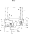
- FIG. 4 is a sectional view of the lid of the pot spinning machine with the opening of the fixed cover closed by the lid.
- FIG. 5 is a side view of the lid attached to the bobbin holder
- FIG. 6 is a perspective view of the same lid.
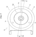
- FIG. 7 is a plan view of the lid attached to the bobbin holder
- FIG. 8 is a sectional view of the lid taken along line VIII-VIII of FIG. 7
- FIG. 9 is a sectional view of the lid taken along line IX-IX of FIG. 7 .
- the lid 50 includes a first lid member 71, a second lid member 72, urging members 73, and an elastic member 74. The following describes these members.
- FIG. 10 is a top perspective view of the first lid member
- FIG. 11 is a bottom perspective view of the first lid member.
- the first lid member 71 is fixed to a gripper 75 of the bobbin holder 42, and the first lid member 71 is, for example, an integral resin molding product.
- the bobbin holder 42 is movable relative to the fixed cover 18 by the operation of the pantograph mechanism 46 that is driven by the power cylinder 51 serving as a drive source.
- the gripper 75 forms a main body of the bobbin holder 42.
- the gripper 75 has a peaked portion 751 at a top end of the gripper 75, and the first lid member 71 is fixed to the gripper 75 by the peaked portion 751.
- the first lid member 71 has a circular shape in a plan view.
- the first lid member 71 has a peripheral wall portion 711, a bottom plate portion 712, and a top plate portion 713 integrally.
- the peripheral wall portion 711 has a ring shape.
- the bottom plate portion 712 has a plurality of pins 714.
- the pins 714 stand on the bottom plate portion 712 vertically.
- the bottom plate portion 712 has a pair of snap-fits 715. Each of the snap-fits 715 is elastically deformable in a thickness direction of the bottom plate portion 712.
- the peripheral wall portion 711 has a plurality of guide grooves 716 and a plurality of hook portions 717 corresponding to the plurality of guide grooves 716 that are formed in an outer peripheral surface of the peripheral wall portion 711.
- the plurality of pins 714 is three pins 714 that are disposed 120 degrees apart in a circle
- the plurality of guide grooves 716 is three guide grooves 716 that are formed corresponding to the three pins 714.
- Each of the hook portions 717 is formed at a top end portion of the corresponding guide groove 716.
- the first lid member 71 has an L-shaped holding portion 718 that is formed in a central portion of a bottom surface of the first lid member 71.
- the holding portion 718 holds the peaked portion 751 of the gripper 75 between the bottom plate portion 712 and the holding portion 718.
- the peaked portion 751 of the gripper 75 is held between the bottom plate portion 712 and the holding portion 718 and the pair of snap-fits 715 is put on a shoulder 752 of the gripper 75 ( FIGS. 5 and 6 ), so that the first lid member 71 is fixed to the gripper 75.
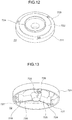
- FIG. 12 is a top perspective view of the second lid member
- FIG. 13 is a bottom perspective view of the second lid member.
- the second lid member 72 is attached to the first lid member 71 such that the second lid member 72 is movable relative to the first lid member 71, and the second lid member 72 is, for example, an integral resin molding product.
- the second lid member 72 has a circular shape in a plan view as well as the first lid member 71.
- the second lid member 72 has a peripheral wall portion 721, a top plate portion 722, and a stepped portion 723 integrally.
- the peripheral wall portion 721 has a ring shape.
- the top plate portion 722 has a projecting portion 724 that has a ring shape.
- the stepped portion 723 is formed outward of the top plate portion 722 in the second lid member 72, and is lower than the top plate portion 722.
- the elastic member 74 is attached to the stepped portion 723.
- the top plate portion 722 has a plurality of ribs 725 that is formed on a bottom surface of the top plate portion 722.
- the ribs 725 radiate from a central portion of the second lid member 72.
- Each of the ribs 725 has, at a distal end of the rib 725, an accommodation hole 726 that has a circular shape in a plan view.
- the accommodation hole 726 accommodates a part of the urging member 73.
- the accommodation hole 726 is formed corresponding to the pin 714 of the first lid member 71.
- the accommodation hole 726 is coaxial with the corresponding pin 714 in a state where the second lid member 72 is attached to the first lid member 71.
- the peripheral wall portion 721 has a plurality of claws 727 that are formed on an inner peripheral surface of the peripheral wall portion 721. Each of the claws 727 corresponds to the guide groove 716 and the hook portion 717.
- the urging member 73 urges the second lid member 72.
- the urging member 73 is a spring member, specifically, a compression coil spring.
- three urging members 73 are disposed so as to correspond to the number of the pins 714 and the number of the accommodation holes 726.
- Each of the urging members 73 is attached to the corresponding pin 714.
- An upper portion of the urging member 73 is accommodated in the accommodation hole 726. Accordingly, the second lid member 72 is urged upward by the three urging members 73.
- the elastic member 74 has a doughnut shape in a plan view.
- the elastic member 74 is attached to the stepped portion 723 of the second lid member 72.
- the elastic member 74 is, for example, made of an elastic material, such as a sponge or a rubber, preferably, made of a soft resin having elastomeric properties.
- the lid 50 includes the first lid member 71, the second lid member 72, the urging members 73, and the elastic member 74, and is assembled as described below.
- each of the three urging members 73 is attached to the corresponding pin 714 of the first lid member 71.
- the first lid member 71 is covered with the second lid member 72 in a state where a position of the pin 714 is aligned with a position of the corresponding accommodation hole 726.
- the second lid member 72 is pushed against an urging force generated by the urging member 73 such that the claw 727 is fitted into the guide groove 716 over the hook portion 717. Accordingly, the second lid member 72 is supported such that the second lid member 72 is movable in the up-and-down direction along the guide groove 716.
- the second lid member 72 is urged upward by the urging force of the urging member 73, and thus, the claw 727 is abutted with the corresponding hook portion 717 by the urging force.
- a gap is secured between the peripheral wall portion 711 of the first lid member 71 and the peripheral wall portion 721 of the second lid member 72 to correct tilt of the lid 50, which will be described later.
- the second lid member 72 is attached to the first lid member 71 such that the second lid member 72 is movable relative to the first lid member 71.
- the drive shaft 52 is driven by the power cylinder 51 illustrated in FIG. 4 to move in the longitudinal direction X of the pot spinning machine 1 in the state illustrated in FIG. 3 , so that the doffing bar 44 is elevated by the operation of the pantograph mechanism 46.
- the lid 50 attached to the bobbin holder 42 moves together with the bobbin holder 42 and the doffing bar 44. Accordingly, the lid 50 moves toward the fixed cover 18, that is, the lid 50 moves upward when the doffing bar 44 moves up, and the lid 50 moves away from the fixed cover 18, that is, the lid 50 moves downward when the doffing bar 44 moves down.
- the lid 50 is moved toward or away from the fixed cover 18 as described above, so that the lid 50 is placed at at least two different positions, specifically, at a close position to close the opening 28 of the fixed cover 18 and at an open position to open the opening 28 of the fixed cover 18. Accordingly, the operation of the pantograph mechanism 46 of the bobbin replacement device 40 allows the lid 50 to open and close the opening 28 of the fixed cover 18. In other words, the lid 50 is placed at the close position and at the open position according to a movement of the movable portion by the drive mechanism.
- FIG. 3 illustrates the lid 50 placed at the open position
- FIG. 4 illustrates the lid 50 placed at the close position.
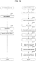
- the lid 50 is placed at the close position by the operation of the pantograph mechanism 46 of the bobbin replacement device 40 (step S21). Accordingly, the lid 50 closes the opening 28 of the fixed cover 18.
- the pot spinning machine 1 forms the cake 24 on the inside wall of the pot 16 (step S11).
- the lid 50 is kept at the close position during a period from the start to the end of formation of the cake 24 by the pot spinning machine 1, which is defined as a period of spinning. Accordingly, the cake 24 is formed in a state where the opening 28 of the fixed cover 18 is closed.
- the lid 50 is moved from the close position to the open position according to the downward movement of the pantograph mechanism 46 of the bobbin replacement device 40 (step S22). Accordingly, the opening 28 of the fixed cover 18 is opened.
- the pantograph mechanism 46 is tilted in the direction A indicated in FIG. 3 by the first tilting operation performed by the tilt mechanism 48 of the bobbin replacement device 40 (step S23). Accordingly, the bobbin holder 42 and the lid 50 are evacuated so as not to interfere with the bobbin 30.
- the elevating rail 31 of the pot spinning machine 1 moves up to insert the empty bobbin 30 into the pot 16 for the rewinding of the yarn of the cake 24 onto the bobbin 30 (step S12).
- the elevating rail 31 of the pot spinning machine 1 moves down to remove the full bobbin 30 from the pot 16 (step S13).
- an empty bobbin different from the bobbin 30 is delivered on a bobbin tray (not illustrated) to a predetermined waiting position.
- the bobbin tray is disposed in a bobbin transportation device that delivers an empty bobbin to the bobbin replacement device 40 of the pot spinning machine 1 and collects a full bobbin from the bobbin replacement device 40 of the pot spinning machine 1.
- the bobbin replacement device 40 attaches an empty bobbin on the bobbin tray to an intermediate peg (not illustrated) with the gripper 75 (step S24) while the pot spinning machine 1 is executing step S12 and step S13.
- the bobbin replacement device 40 uses the operation of the pantograph mechanism 46 and the operation of the tilt mechanism 48 to perform this operation.
- pantograph mechanism 46 is moved in the direction B indicated in FIG. 3 by the second tilting operation performed by the tilt mechanism 48 (step S25). This restores the pantograph mechanism 46 to its vertical posture.
- the gripper 75 and the lid 50 are positioned below the pot 16 in this state.
- the elevating rail 31 moves up to insert a top end portion of the bobbin 30 into the gripper 75, and is driven by the bobbin holder 42 to hold the full bobbin 30 with the gripper 75 (step S26).
- the elevating rail 31 then moves down to remove the full bobbin 30 from the bobbin support member 32 (step S27).
- the bobbin replacement device 40 puts the full bobbin 30 on the bobbin tray by using the operation of the pantograph mechanism 46 and the operation of the tilt mechanism 48 (step S28).
- the gripper 75 of the bobbin holder 42 of the bobbin replacement device 40 holds the empty bobbin attached to the intermediate peg, and attaches the empty bobbin to the bobbin support member 32 by using the operation of the pantograph mechanism 46 and the operation of the tilt mechanism 48 (step S29).
- FIG. 4 illustrates the lid 50 placed at the close position in step S21.
- the elastic member 74 of the lid 50 is pressed to the bottom end of the fixed cover 18.
- the elastic member 74 is attached firmly to the bottom end of the fixed cover 18. This increases a sealing performance at a region of contact between the fixed cover 18 and the lid 50. Accordingly, this further reduces air leak from the fixed cover 18 effectively. If a foreign substance, such as cotton fly or a yarn, enters the region of contact between the fixed cover 18 and the lid 50, the elastic member 74 is deformed locally at a point where the foreign substance has entered. Accordingly, this configuration reduces air leak that may be caused by the foreign substance.
- the lid 50 When the lid 50 is placed at the close position by the operation of the pantograph mechanism 46, the lid 50 may be tilted or tilted at various angles due to a part dimension error or assembling error that may occur in the bobbin replacement device 40.
- the second lid member 72 is movably attached to the first lid member 71 and is urged upward by the urging member 73 in this embodiment.
- the second lid member 72 is pressed to the bottom end of the fixed cover 18 by the urging force generated by the urging member 73.
- This configuration allows the second lid member 72 to be moved relative to the first lid member 71 so as to correct the tilt of the lid 50 under the urging force of the urging member 73, even if the second lid member 72 is pressed disproportionately to the bottom end of the fixed cover 18 due to the tilt of the lid 50.
- a height at which the lid 50 is placed may vary. However, such variation in height is absorbed by a stroke of the spring member of the urging member 73 when the second lid member 72 is pressed to the bottom end of the fixed cover 18.
- this configuration of the urging member 73 secures an appropriate pressing force to press the second lid member 72 to the bottom end of the fixed cover 18 by using flexure of the spring member of the urging member 73.
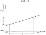
- FIG. 15 is a graph illustrating a relationship between the pressing force and a height at which the lid is placed.
- the vertical axis in FIG. 15 represents the pressing force for pressing the second lid member 72 to the bottom end of the fixed cover 18, and the horizontal axis represents a height at which the lid 50 is placed at the close position by the operation of the pantograph mechanism 46.
- the flexure of the spring member of the urging member 73 is gradually increased with an increase in height at which the lid 50 is placed, so that the pressing force for pressing the second lid member 72 is increased.
- This enables an appropriate pressing force for pressing the second lid member 72 to be secured within an appropriate pressing force range F indicated in FIG. 15 as long as the variation in height at which the lid 50 is placed is within a range H indicated in FIG. 15 .
- the pantograph mechanism 46 When the doffing bar 44 is moved down by the operation of the pantograph mechanism 46 in a state where the lid 50 is placed at the close position, the lid 50 moves away from the fixed cover 18. This movement moves the lid 50 from the close position to the open position, thereby opening the opening 28 of the fixed cover 18. Furthermore, when the elevating rail 31 moves up to insert the bobbin 30 attached to the bobbin support member 32 into the pot 16 or moves down to remove the bobbin 30 from the pot 16, the pantograph mechanism 46 is tilted in the direction A indicated in FIG. 3 by the operation of the tilt mechanism 48 in a state where the lid 50 is placed at the open position, so that the gripper 75 and the lid 50 are evacuated so as not to interfere with the bobbin 30.
- the pot spinning machine 1 has a configuration that enables the lid 50 to be placed at the close position and at the open position by using the operation of the pantograph mechanism 46, which is included in the bobbin replacement device 40 for replacing the bobbin, to move the doffing bar 44 together with the bobbin holder 42 in the up-and-down direction.
- This configuration allows the lid 50 to open and close the opening 28 of the fixed cover 18 without mounting of a drive source for operating the lid 50 (hereinafter referred to as a lid drive source) to the pot spinning machine 1 or the bobbin replacement device 40. Accordingly, this configuration reduces the cost of the pot spinning machine 1, compared with a case where the pot spinning machine 1 includes the lid drive source.
- the lid drive source may interfere with other parts of the pot spinning machine 1.
- the pot spinning machine 1 according to this embodiment does not need the lid drive source, so that this pot spinning machine 1 does not cause the interference between the parts of the pot spinning machine 1 and the drive source.
- the second lid member 72 is attached to the first lid member 71 such that the second lid member 72 is movable relative to the first lid member 71.
- the second lid member 72 is pressed to the bottom end of the fixed cover 18 by the urging force of the urging members 73. Accordingly, if the lid 50 is tilted due to a part dimension error or assembling error that may occur in the bobbin replacement device 40, the second lid member 72 is moved in a direction to correct the tilt of the lid 50. Accordingly, the movement of the second lid member 72 relative to the first lid member 71 corrects the tilt of the lid 50.
- the urging member 73 is a spring member, so that this configuration enables variation in height at which the lid 50 is placed at the close position to be absorbed by a stroke of the spring member. Additionally, this configuration secures an appropriate pressing force to press the second lid member 72 to the bottom end of the fixed cover 18 by using flexure of the spring member of the urging member 73.
- the elastic member 74 is disposed in a portion of the second lid member 72 that is pressed to the fixed cover 18. This configuration increases the sealing performance at the contact region between the fixed cover 18 and the lid 50 to reduce the air leak.
- the lid 50 is attached to the bobbin holder 42 to open and close the opening 28 of the fixed cover 18.
- the present disclosure is not limited to this embodiment, and the lid 50 may be attached to the doffing bar 44.
- the movable portion of the present disclosure is not limited to the bobbin holder 42 and the doffing bar 44, and the movable portion is, at least, a portion that is moved in the up-and-down direction by the operation of the pantograph mechanism 46.
- the first lid member 71 has the holding portion 718 and the pair of snap-fits 715 to fix the first lid member 71 to the gripper 75.
- the present disclosure is not limited to this configuration, and the first lid member 71 may be fixed to the gripper 75 by a fastening means, such as a bolt or an adhesive material.
- the urging member is, preferably, a compression coil spring.
- the present disclosure is not limited to this configuration, and the urging member may be a spring member, such as a leaf spring or a torsion coil spring, or a member other than a spring member.
- the pot 16 is directly surrounded by the fixed cover 18.
- the pot 16 may be indirectly surrounded by the fixed cover 18 via a rotary cover, which is not illustrated. The rotary cover rotates together with the pot 16.
- the lid 50 for closing the opening 28 of the fixed cover 18 may have a hole in a central portion of the lid 50 for the following reason. If the pot 16 is rotated at a high rotational speed with the opening 28 of the fixed cover 18 opened, a pressure in a space near the central axis K of the pot 16 becomes a negative pressure and a pressure in a space that is on an outer peripheral side of the pot 16 and away from the central axis K of the pot 16 becomes a positive pressure. This causes air to flow into the pot 16 in the space near the central axis K of the pot 16 and causes air to flow out of the pot 16 in the space on the outer peripheral side and away from the central axis K of the pot 16.
- the lid 50 prevents the air from flowing out of the pot 16 on the outer peripheral side of the pot 16. This does not allow the air to flow into the pot 16 through the hole that may be formed in the central portion of the lid 50. Accordingly, the pot spinning machine achieves advantageous effects that reduce air leak and suction of cotton fly, even if the lid 50 has a hole whose diameter is equal to or less than 50% of an inner diameter of the pot 16.
- a bobbin replacement device (40) for a pot spinning machine (1) is configured to replace a full bobbin (30) with an empty bobbin (30).
- the pot spinning machine (1) includes a pot (16) and a fixed cover (18) surrounding the pot (16) and having an opening (28) that opens downward.
- the bobbin replacement device (40) includes a drive mechanism (46, 48), a movable portion (42, 44), and a lid (50).
- the movable portion (42, 44) is moved in a predetermined direction (A, B) by the drive mechanism (46, 48).
- the lid (50) is attached to the movable portion (42) such that the lid (50) is moved together with the movable portion (42, 44).
- the lid (50) is placed at a close position to close the opening (28) of the fixed cover (18) and placed at an open position to open the opening (28) of the fixed cover (18) according to the movement of the movable portion (42, 44) by the drive mechanism (46, 48).
Landscapes
- Engineering & Computer Science (AREA)
- Mechanical Engineering (AREA)
- Textile Engineering (AREA)
- Spinning Or Twisting Of Yarns (AREA)
Abstract
Description
- The present disclosure relates to a bobbin replacement device for a pot spinning machine.
- A pot spinning machine forms a cake by depositing yarn, which has been delivered into a pot through a yarn introduction pipe, against an inside wall of the pot by a centrifugal force involved in fast rotation of the pot, and the pot spinning machine rewinds the yarn onto a bobbin in the pot. If the pot is rotated with an opening of the pot opened, windage loss in the pot is increased by air that flows into the pot through the opening and air that flows out of the pot through the opening during the rotation of the pot. Furthermore, the air that flows into the pot may bring cotton fly into the pot, and the cotton fly mixed with the yarn degrades the quality of the yarn. In addition, the fast rotation of the pot with the pot exposed may reduce the safety around the pot.
- Known pot spinning machines include a fixed cover that surrounds the pot and a lid that closes an opening of the fixed cover, in order to reduce the windage loss in the pot. In some pot spinning machines, the pot has a downward opening, and the fixed cover surrounding the pot has an opening that is closed by an openable lid (for example, refer to a pot spinning machine disclosed in Japanese Patent Application Publication No.
08-060430 - When the openable lid closes the downward opening of the fixed cover, the lid has to be raised against gravitational force that is acting on the lid. This requires a drive source to be mounted to the pot spinning machine to operate the lid. However, mounting of the drive source increases the cost of the pot spinning machine.
- The present disclosure has been made to solve the above-described problem and is directed to providing a bobbin replacement device for a pot spinning machine in which a downward opening of a fixed cover is opened and closed with a lid without mounting of a drive source for operating the lid to the pot spinning machine.
- In accordance with an aspect of the present disclosure, there is provided a bobbin replacement device for a pot spinning machine. The pot spinning machine includes a pot having an opening that opens downward, a fixed cover surrounding the pot and having an opening that opens downward, and a bobbin support part supporting a bobbin below the pot. The bobbin replacement device is configured to replace the full bobbin with an empty bobbin. The bobbin replacement device for the pot spinning machine includes a drive mechanism for replacing the bobbin, a movable portion, and a lid. The movable portion includes a bobbin holder that holds the bobbin at replacement of the bobbin, and is moved in a predetermined direction by the drive mechanism. The lid is attached to the movable portion such that the lid is moved together with the movable portion. The lid is placed at a close position to close the opening of the fixed cover and placed at an open position to open the opening of the fixed cover according to the movement of the movable portion by the drive mechanism.
- Other aspects and advantages of the disclosure will become apparent from the following description, taken in conjunction with the accompanying drawings, illustrating by way of example the principles of the disclosure.
- The present disclosure together with objects and advantages thereof, may best be understood by reference to the following description of the embodiments together with the accompanying drawings in which:
-
FIG. 1 is a schematic view illustrating an exemplary configuration of a pot spinning machine according to an embodiment of the present disclosure; -
FIG. 2 is a schematic front view illustrating an exemplary configuration of a bobbin replacement device of the pot spinning machine according to the embodiment of the present disclosure; -
FIG. 3 is a schematic side view illustrating the exemplary configuration of the bobbin replacement device of the pot spinning machine according to the embodiment of the present disclosure; -
FIG. 4 is a sectional view of a lid of the pot spinning machine with an opening of a fixed cover closed by the lid; -
FIG. 5 is a side view of the lid attached to a bobbin holder; -
FIG. 6 is a perspective view of the lid attached to the bobbin holder; -
FIG. 7 is a plan view of the lid attached to the bobbin holder; -
FIG. 8 is a sectional view of the lid taken along line VIII-VIII ofFIG. 7 ; -
FIG. 9 is a sectional view of the lid taken along line IX-IX ofFIG. 7 ; -
FIG. 10 is a top perspective view of a first lid member; -
FIG. 11 is a bottom perspective view of the first lid member; -
FIG. 12 is a top perspective view of a second lid member; -
FIG. 13 is a bottom perspective view of the second lid member; -
FIG. 14 is a flow chart illustrating a relationship between an operation of the pot spinning machine and an operation of the bobbin replacement device; and -
FIG. 15 is a graph illustrating a relationship between a pressing force and a height at which the lid is placed. - The following will describe an embodiment of the present disclosure in detail with reference to the accompanying drawings.
-
FIG. 1 is a schematic view illustrating an exemplary configuration of a pot spinning machine according to an embodiment of the present disclosure. - As illustrated in
FIG. 1 , apot spinning machine 1 includes adrafting device 10, ayarn suction pipe 12, ayarn introduction pipe 14, apot 16, afixed cover 18, and abobbin support part 20. These elements cooperate to form a single spindle that represents a unit of spinning. Thepot spinning machine 1 generally includes a plurality of spindles, but the following will focus on one of the spindles. - The
drafting device 10 is a device that draws out a yarn material. Thedrafting device 10 includes multiple pairs of rollers, such as a pair ofback rollers 21, a pair ofmiddle rollers 22, and a pair offront rollers 23. The pair ofback rollers 21, the pair ofmiddle rollers 22, and the pair offront rollers 23 are arranged in this order from upstream to downstream of a roving feed direction. - The pairs of
rollers rollers middle rollers 22 is greater than the rpm of the pair ofback rollers 21, and the rpm of the pair offront rollers 23 is greater than the rpm of the pair ofmiddle rollers 22. As described above, the rpm of the pairs ofrollers drafting device 10 thinly draws out the yarn material by using the difference in rpm among the pairs ofrollers rollers - The
yarn suction pipe 12 draws ayarn 25 supplied by thedrafting device 10, and feeds the drawnyarn 25 into theyarn introduction pipe 14. Theyarn suction pipe 12 uses air swirl flow to introduce theyarn 25, which has been drawn out by thedrafting device 10. - The
yarn introduction pipe 14 introduces theyarn 25, which has been fed from thedrafting device 10 through theyarn suction pipe 12, into thepot 16. Theyarn introduction pipe 14 has a long thin tube-like shape. Theyarn introduction pipe 14 has a circular cross section in a direction perpendicular to a longitudinal direction of theyarn introduction pipe 14. Theyarn introduction pipe 14 is disposed downstream of thedrafting device 10, and is coaxial with theyarn suction pipe 12 and thepot 16. Theyarn introduction pipe 14 penetrates through an upper portion of thepot 16 to be inserted into thepot 16. Theyarn introduction pipe 14 has ayarn inlet 14a and ayarn outlet 14b at a top end and a bottom end of theyarn introduction pipe 14, respectively. Theyarn 25 fed into theyarn introduction pipe 14 through theyarn inlet 14a is discharged from theyarn outlet 14b of theyarn introduction pipe 14. - The
pot 16 is used for formation of acake 24 and yarn rewinding. Thecake 24 is a deposit of yarn that is formed on an inside wall of thepot 16 by operation of theyarn introduction pipe 14, which will be described later. Thepot 16 has a cylindrical shape. Thepot 16 is rotatable with respect to a central axis K of thepot 16. The central axis K of thepot 16 is parallel to a vertical direction. Accordingly, one side of thepot 16 is an upper side, and the other side is a lower side in the central axis K direction. Thepot 16 has anopening 26 at a bottom end of thepot 16. Theopening 26 of thepot 16 has a diameter equal to an inner diameter of thepot 16, and theopening 26 opens downward. - The fixed
cover 18 is disposed surrounding thepot 16. The fixedcover 18 is fixed to a fixingportion 27. The fixedcover 18 has a cylindrical shape, and has a diameter greater than that of thepot 16. The fixedcover 18 is coaxial with thepot 16. The fixedcover 18 has, at a top end of the fixedcover 18, an opening that is closed by the fixingportion 27. The fixedcover 18 has anopening 28 at a bottom end of the fixedcover 18. Theopening 28 of the fixedcover 18 has a diameter equal to an inner diameter of the fixedcover 18, and theopening 28 opens downward. Theopening 28 of the fixedcover 18 is disposed below theopening 26 of thepot 16. - The
bobbin support part 20 supports abobbin 30 below thepot 16. Thebobbin support part 20 includes an elevatingrail 31 and abobbin support member 32. The elevatingrail 31 is configured to move up and down. Thebobbin support member 32 is attached to the elevatingrail 31. Thebobbin support member 32 is a portion of thebobbin support part 20 to which thebobbin 30 is attachable. Thebobbin support member 32 is coaxial with theyarn introduction pipe 14 and thepot 16 such that thebobbin support member 32 faces theyarn introduction pipe 14 on the central axis K of thepot 16. Accordingly, thebobbin 30 faces theyarn introduction pipe 14 on the central axis K of thepot 16 in a state where thebobbin 30 is attached to thebobbin support member 32. - The
bobbin 30 is tapered such that an outer diameter of thebobbin 30 changes sequentially from one end to the other end of thebobbin 30 in a direction of a central axis of thebobbin 30. Thebobbin 30 is supported by thebobbin support member 32 such that thebobbin 30 stands on thebobbin support member 32 vertically. The outer diameter of thebobbin 30 is smaller than the smallest diameter of thecake 24 formed on the inside wall of thepot 16. This configuration prevents thebobbin 30 from contacting thecake 24 when thebobbin 30 is inserted into thepot 16 through theopening 26 of thepot 16. - The following will describe the operation of the pot spinning machine according to the embodiment of the present disclosure.
- First, the drafting
device 10 draws out the yarn material, such as roving. Theyarn 25, which has been drawn out by the draftingdevice 10, is drawn into theyarn suction pipe 12 by air swirl flow or the like, and fed into theyarn introduction pipe 14 through theyarn inlet 14a. Theyarn 25 fed into theyarn introduction pipe 14 is discharged through theyarn outlet 14b of theyarn introduction pipe 14. Meanwhile, thepot 16 is rotated at a predetermined rotational speed. The fixedcover 18 is stationary regardless of the rotation of thepot 16. - The
yarn 25 discharged from theyarn outlet 14b of theyarn introduction pipe 14 as described above is pressed onto the inside wall of thepot 16 by centrifugal force generated by the rotation of thepot 16. Theyarn 25 discharged from theyarn outlet 14b of theyarn introduction pipe 14 is twisted by the rotation of thepot 16 and wound onto the inside wall of thepot 16. Theyarn introduction pipe 14 displaces its position relatively downward while reciprocating at predetermined intervals in an up-and-down direction. Accordingly, theyarn 25 is wound onto the inside wall of thepot 16 while displacing its winding position, so that thecake 24 is formed on the inside wall of thepot 16. - The elevating
rail 31 moves up to insert thebobbin 30 into thepot 16 while thepot 16 is rotating. Then, the yarn of thecake 24 is rewound onto thebobbin 30. The yarn is rewound onto thebobbin 30, for example, by a yarn disentangling member (not illustrated) contacting an end of the yarn of thecake 24. - After the whole yarn of the
cake 24 is rewound onto thebobbin 30, the elevatingrail 31 moves down to remove thebobbin 30 from thepot 16. Thebobbin 30 removed from thepot 16 is a full bobbin onto which a predetermined amount of the yarn has been rewound. -
FIG. 2 is a schematic front view illustrating an exemplary configuration of a bobbin replacement device of the pot spinning machine according to the embodiment of the present disclosure, andFIG. 3 is a schematic side view illustrating the same. - A
bobbin replacement device 40 is a device configured to replace thebobbin 30, which is supported by thebobbin support part 20 and is a full bobbin, with an empty bobbin. Thebobbin replacement device 40 according to this embodiment is a simultaneous bobbin replacement device that is configured to simultaneously perform a bobbin replacement for all spindles of thepot spinning machine 1. Thebobbin replacement device 40 includes a bobbin holder 42 (FIG. 3 ) that holds thebobbin 30 at the replacement of thebobbin 30, a doffingbar 44 that supports thebobbin holder 42, apantograph mechanism 46 that elevates the doffingbar 44, and atilt mechanism 48 that tilts thepantograph mechanism 46. Thebobbin holder 42 and the doffingbar 44 cooperate to serve as a movable portion of the present disclosure, in other words, the movable portion of the present disclosure includes thebobbin holder 42. Thepantograph mechanism 46 and thetilt mechanism 48 cooperate to serve as a drive mechanism of the present disclosure for replacing the bobbin. - The
bobbin holder 42 may be, for example, a bobbin holder disclosed in Japanese Patent Application Publication No.09-087931 09-087931 - The
pantograph mechanism 46 elevates the doffingbar 44 while keeping the doffingbar 44 in a horizontal posture in a front view as illustrated inFIG. 2 . As illustrated inFIG. 3 , thebobbin holder 42 is attached to the doffingbar 44. Thebobbin replacement device 40 further includes alid 50 that is attached to thebobbin holder 42. Thelid 50 opens and closes theopening 28 of the fixedcover 18. Thelid 50 is attached to thebobbin holder 42 such that thelid 50 is moved together with thebobbin holder 42 and the doffingbar 44. The configuration of thelid 50 will be described later. - The
pantograph mechanism 46 is supported rotatably with respect to thedrive shaft 52. Thepantograph mechanism 46 includes afirst link 53 and asecond link 54. Thefirst link 53 has afirst end 53a that is coupled to the doffingbar 44 with a pin and asecond end 53b that is coupled to amovable bracket 55 with a pin. Pin coupling is a coupling method to rotatably couple one member to another member with a pin. Thedrive shaft 52 is disposed such that thedrive shaft 52 is driven by apower cylinder 51 to reciprocally move in a longitudinal direction X of thepot spinning machine 1. Themovable bracket 55 is fixed to thedrive shaft 52 such that themovable bracket 55 is movable together with thedrive shaft 52 in the longitudinal direction X of thepot spinning machine 1. - The
second link 54 is half the length of thefirst link 53. Thesecond link 54 has afirst end 54a that is coupled to a middle portion of thefirst link 53 with a pin in the longitudinal direction. Thesecond link 54 further has asecond end 54b that is coupled to asupport bracket 56 with a pin. Thesupport bracket 56 is restrained by a fixedbracket 57 so as not to move in an axial direction of thedrive shaft 52. Thesupport bracket 56 is rotatably attached to thedrive shaft 52 such that thedrive shaft 52 is movable in the longitudinal direction X of thepot spinning machine 1. - The
tilt mechanism 48 is configured as described below. - The
support bracket 56 includes alever 56a. Thelever 56a is disposed integrally with thesupport bracket 56. Thelever 56a protrudes in a direction perpendicular to the axial direction of thedrive shaft 52. Arod 59 is disposed in a vicinity of a distal end of thelever 56a. Therod 59 is movable in a direction parallel to the axial direction of thedrive shaft 52. Therod 59 is driven to move reciprocally in the direction parallel to the axial direction of thedrive shaft 52 by an air cylinder that is not illustrated. - A
bracket 61 is disposed in a vicinity of therod 59. Thebracket 61 is fixed at a position that corresponds to a position of thesupport bracket 56 in the longitudinal direction X of thepot spinning machine 1. A drivinglever 62 that has a V-shape in a side view is rotatably supported by thebracket 61 at a bending point of the drivinglever 62. The drivinglever 62 is rotatably coupled to therod 59 at one end of the drivinglever 62. The drivinglever 62 is further coupled to thelever 56a at the other end of the drivinglever 62 via alink 63. The drivinglever 62 is pivoted by the reciprocating motion of therod 59 to move up and down thelink 63, so that the distal end of thelever 56a is moved up and down via thelink 63. That is, the above-described air cylinder drives thesupport bracket 56 to pivot together with thelever 56a with respect to thedrive shaft 52, thereby pivoting thewhole pantograph mechanism 46 together with thesupport bracket 56 with respect to thedrive shaft 52. - The following will describe the operation of the bobbin replacement device according to the embodiment of the present disclosure.
- The
bobbin replacement device 40 performs two operations. One of the operations is an elevating operation performed by thepantograph mechanism 46 and the other is a tilting operation performed by thetilt mechanism 48. - The
power cylinder 51 drives thedrive shaft 52 to move in the longitudinal direction X of thepot spinning machine 1 such that themovable bracket 55 moves toward or away from thesupport bracket 56 in the longitudinal direction X of thepot spinning machine 1. When themovable bracket 55 moves toward thesupport bracket 56, thefirst link 53 and thesecond link 54 cooperate to move up the doffingbar 44. When themovable bracket 55 moves away from thesupport bracket 56, thefirst link 53 and thesecond link 54 cooperate to move down the doffingbar 44. Accordingly, the doffingbar 44 is moved in the up-and-down direction, that is, the doffingbar 44 is elevated by the operation of thepantograph mechanism 46 that is driven by thepower cylinder 51 serving as a drive source. - Meanwhile, the air cylinder drives the
rod 59 to move in the axial direction of thedrive shaft 52, thereby pivoting the drivinglever 62 to move up and down thelink 63. The up-down motion of thelink 63 moves up and down thelever 56a. This pivots thesupport bracket 56 with respect to thedrive shaft 52. Since thepantograph mechanism 46 is supported by thedrive shaft 52 via themovable bracket 55 and thesupport bracket 56, thewhole pantograph mechanism 46 is pivoted together with thesupport bracket 56 with respect to thedrive shaft 52 by pivoting of thesupport bracket 56 with respect to thedrive shaft 52. This allows thepantograph mechanism 46 to be tilted in a predetermined direction A from its vertical posture illustrated inFIG. 3 , and allows the tiltedpantograph mechanism 46 to be restored to its vertical posture. Accordingly, thebobbin holder 42 and the doffingbar 44 are moved in the direction A or a predetermined direction B opposite to the direction A indicated inFIG. 3 by the operation of thetilt mechanism 48 that is driven by the air cylinder serving as a drive source. In the following description, "the first tilting operation" is the operation of thetilt mechanism 48 to move thebobbin holder 42 and the doffingbar 44 together with thepantograph mechanism 46 in the direction A indicated inFIG. 3 , and "the second tilting operation" is the operation of thetilt mechanism 48 to move thebobbin holder 42 and the doffingbar 44 together with thepantograph mechanism 46 in the direction B indicated inFIG. 3 . -
FIG. 4 is a sectional view of the lid of the pot spinning machine with the opening of the fixed cover closed by the lid.FIG. 5 is a side view of the lid attached to the bobbin holder, andFIG. 6 is a perspective view of the same lid.FIG. 7 is a plan view of the lid attached to the bobbin holder, andFIG. 8 is a sectional view of the lid taken along line VIII-VIII ofFIG. 7 , andFIG. 9 is a sectional view of the lid taken along line IX-IX ofFIG. 7 . - The
lid 50 includes afirst lid member 71, asecond lid member 72, urgingmembers 73, and anelastic member 74. The following describes these members. -
FIG. 10 is a top perspective view of the first lid member, andFIG. 11 is a bottom perspective view of the first lid member. - The
first lid member 71 is fixed to agripper 75 of thebobbin holder 42, and thefirst lid member 71 is, for example, an integral resin molding product. Thebobbin holder 42 is movable relative to the fixedcover 18 by the operation of thepantograph mechanism 46 that is driven by thepower cylinder 51 serving as a drive source. Thegripper 75 forms a main body of thebobbin holder 42. Thegripper 75 has apeaked portion 751 at a top end of thegripper 75, and thefirst lid member 71 is fixed to thegripper 75 by thepeaked portion 751. - The
first lid member 71 has a circular shape in a plan view. Thefirst lid member 71 has aperipheral wall portion 711, abottom plate portion 712, and atop plate portion 713 integrally. Theperipheral wall portion 711 has a ring shape. Thebottom plate portion 712 has a plurality ofpins 714. Thepins 714 stand on thebottom plate portion 712 vertically. Thebottom plate portion 712 has a pair of snap-fits 715. Each of the snap-fits 715 is elastically deformable in a thickness direction of thebottom plate portion 712. - The
peripheral wall portion 711 has a plurality ofguide grooves 716 and a plurality ofhook portions 717 corresponding to the plurality ofguide grooves 716 that are formed in an outer peripheral surface of theperipheral wall portion 711. In this embodiment, for example, the plurality ofpins 714 is threepins 714 that are disposed 120 degrees apart in a circle, and the plurality ofguide grooves 716 is threeguide grooves 716 that are formed corresponding to the threepins 714. Each of thehook portions 717 is formed at a top end portion of thecorresponding guide groove 716. Thefirst lid member 71 has an L-shapedholding portion 718 that is formed in a central portion of a bottom surface of thefirst lid member 71. The holdingportion 718 holds thepeaked portion 751 of thegripper 75 between thebottom plate portion 712 and the holdingportion 718. Thepeaked portion 751 of thegripper 75 is held between thebottom plate portion 712 and the holdingportion 718 and the pair of snap-fits 715 is put on ashoulder 752 of the gripper 75 (FIGS. 5 and6 ), so that thefirst lid member 71 is fixed to thegripper 75. -
FIG. 12 is a top perspective view of the second lid member, andFIG. 13 is a bottom perspective view of the second lid member. - The
second lid member 72 is attached to thefirst lid member 71 such that thesecond lid member 72 is movable relative to thefirst lid member 71, and thesecond lid member 72 is, for example, an integral resin molding product. Thesecond lid member 72 has a circular shape in a plan view as well as thefirst lid member 71. Thesecond lid member 72 has aperipheral wall portion 721, atop plate portion 722, and a steppedportion 723 integrally. Theperipheral wall portion 721 has a ring shape. Thetop plate portion 722 has a projectingportion 724 that has a ring shape. The steppedportion 723 is formed outward of thetop plate portion 722 in thesecond lid member 72, and is lower than thetop plate portion 722. As illustrated inFIG. 8 , theelastic member 74 is attached to the steppedportion 723. - The
top plate portion 722 has a plurality ofribs 725 that is formed on a bottom surface of thetop plate portion 722. Theribs 725 radiate from a central portion of thesecond lid member 72. Each of theribs 725 has, at a distal end of therib 725, anaccommodation hole 726 that has a circular shape in a plan view. Theaccommodation hole 726 accommodates a part of the urgingmember 73. Theaccommodation hole 726 is formed corresponding to thepin 714 of thefirst lid member 71. Theaccommodation hole 726 is coaxial with thecorresponding pin 714 in a state where thesecond lid member 72 is attached to thefirst lid member 71. Theperipheral wall portion 721 has a plurality ofclaws 727 that are formed on an inner peripheral surface of theperipheral wall portion 721. Each of theclaws 727 corresponds to theguide groove 716 and thehook portion 717. - The urging
member 73 urges thesecond lid member 72. In this embodiment, for example, the urgingmember 73 is a spring member, specifically, a compression coil spring. In this embodiment, three urgingmembers 73 are disposed so as to correspond to the number of thepins 714 and the number of the accommodation holes 726. Each of the urgingmembers 73 is attached to thecorresponding pin 714. An upper portion of the urgingmember 73 is accommodated in theaccommodation hole 726. Accordingly, thesecond lid member 72 is urged upward by the three urgingmembers 73. - The
elastic member 74 has a doughnut shape in a plan view. Theelastic member 74 is attached to the steppedportion 723 of thesecond lid member 72. Theelastic member 74 is, for example, made of an elastic material, such as a sponge or a rubber, preferably, made of a soft resin having elastomeric properties. - In this embodiment, the
lid 50 includes thefirst lid member 71, thesecond lid member 72, the urgingmembers 73, and theelastic member 74, and is assembled as described below. - First, each of the three urging
members 73 is attached to thecorresponding pin 714 of thefirst lid member 71. Next, thefirst lid member 71 is covered with thesecond lid member 72 in a state where a position of thepin 714 is aligned with a position of thecorresponding accommodation hole 726. Thesecond lid member 72 is pushed against an urging force generated by the urgingmember 73 such that theclaw 727 is fitted into theguide groove 716 over thehook portion 717. Accordingly, thesecond lid member 72 is supported such that thesecond lid member 72 is movable in the up-and-down direction along theguide groove 716. Thesecond lid member 72 is urged upward by the urging force of the urgingmember 73, and thus, theclaw 727 is abutted with thecorresponding hook portion 717 by the urging force. In a radial direction of thelid 50, a gap is secured between theperipheral wall portion 711 of thefirst lid member 71 and theperipheral wall portion 721 of thesecond lid member 72 to correct tilt of thelid 50, which will be described later. - Since the
lid 50 is assembled as described above, thesecond lid member 72 is attached to thefirst lid member 71 such that thesecond lid member 72 is movable relative to thefirst lid member 71. - The following will describe the operation of the
lid 50 to open and close theopening 28 of the fixedcover 18. - The
drive shaft 52 is driven by thepower cylinder 51 illustrated inFIG. 4 to move in the longitudinal direction X of thepot spinning machine 1 in the state illustrated inFIG. 3 , so that the doffingbar 44 is elevated by the operation of thepantograph mechanism 46. Thelid 50 attached to thebobbin holder 42 moves together with thebobbin holder 42 and the doffingbar 44. Accordingly, thelid 50 moves toward the fixedcover 18, that is, thelid 50 moves upward when the doffingbar 44 moves up, and thelid 50 moves away from the fixedcover 18, that is, thelid 50 moves downward when the doffingbar 44 moves down. - The
lid 50 is moved toward or away from the fixedcover 18 as described above, so that thelid 50 is placed at at least two different positions, specifically, at a close position to close theopening 28 of the fixedcover 18 and at an open position to open theopening 28 of the fixedcover 18. Accordingly, the operation of thepantograph mechanism 46 of thebobbin replacement device 40 allows thelid 50 to open and close theopening 28 of the fixedcover 18. In other words, thelid 50 is placed at the close position and at the open position according to a movement of the movable portion by the drive mechanism.FIG. 3 illustrates thelid 50 placed at the open position, andFIG. 4 illustrates thelid 50 placed at the close position. - The following will describe the relationship between the operation of the pot spinning machine and the operation of the bobbin replacement device with reference to
FIG. 14 . - First, the
lid 50 is placed at the close position by the operation of thepantograph mechanism 46 of the bobbin replacement device 40 (step S21). Accordingly, thelid 50 closes theopening 28 of the fixedcover 18. - Next, the
pot spinning machine 1 forms thecake 24 on the inside wall of the pot 16 (step S11). Thelid 50 is kept at the close position during a period from the start to the end of formation of thecake 24 by thepot spinning machine 1, which is defined as a period of spinning. Accordingly, thecake 24 is formed in a state where theopening 28 of the fixedcover 18 is closed. - The
lid 50 is moved from the close position to the open position according to the downward movement of thepantograph mechanism 46 of the bobbin replacement device 40 (step S22). Accordingly, theopening 28 of the fixedcover 18 is opened. - The
pantograph mechanism 46 is tilted in the direction A indicated inFIG. 3 by the first tilting operation performed by thetilt mechanism 48 of the bobbin replacement device 40 (step S23). Accordingly, thebobbin holder 42 and thelid 50 are evacuated so as not to interfere with thebobbin 30. - Next, the elevating
rail 31 of thepot spinning machine 1 moves up to insert theempty bobbin 30 into thepot 16 for the rewinding of the yarn of thecake 24 onto the bobbin 30 (step S12). - After the yarn rewinding, the elevating
rail 31 of thepot spinning machine 1 moves down to remove thefull bobbin 30 from the pot 16 (step S13). - While the
pot spinning machine 1 is forming thecake 24 at step S11, an empty bobbin different from thebobbin 30 is delivered on a bobbin tray (not illustrated) to a predetermined waiting position. The bobbin tray is disposed in a bobbin transportation device that delivers an empty bobbin to thebobbin replacement device 40 of thepot spinning machine 1 and collects a full bobbin from thebobbin replacement device 40 of thepot spinning machine 1. - The
bobbin replacement device 40 attaches an empty bobbin on the bobbin tray to an intermediate peg (not illustrated) with the gripper 75 (step S24) while thepot spinning machine 1 is executing step S12 and step S13. Thebobbin replacement device 40 uses the operation of thepantograph mechanism 46 and the operation of thetilt mechanism 48 to perform this operation. - Next, the
pantograph mechanism 46 is moved in the direction B indicated inFIG. 3 by the second tilting operation performed by the tilt mechanism 48 (step S25). This restores thepantograph mechanism 46 to its vertical posture. Thegripper 75 and thelid 50 are positioned below thepot 16 in this state. - Next, the elevating
rail 31 moves up to insert a top end portion of thebobbin 30 into thegripper 75, and is driven by thebobbin holder 42 to hold thefull bobbin 30 with the gripper 75 (step S26). - The elevating
rail 31 then moves down to remove thefull bobbin 30 from the bobbin support member 32 (step S27). - The
bobbin replacement device 40 puts thefull bobbin 30 on the bobbin tray by using the operation of thepantograph mechanism 46 and the operation of the tilt mechanism 48 (step S28). - The
gripper 75 of thebobbin holder 42 of thebobbin replacement device 40 holds the empty bobbin attached to the intermediate peg, and attaches the empty bobbin to thebobbin support member 32 by using the operation of thepantograph mechanism 46 and the operation of the tilt mechanism 48 (step S29). - Then, the
pot spinning machine 1 and thebobbin replacement device 40 repeat the above-described operations. -
FIG. 4 illustrates thelid 50 placed at the close position in step S21. In this state, theelastic member 74 of thelid 50 is pressed to the bottom end of the fixedcover 18. Theelastic member 74 is attached firmly to the bottom end of the fixedcover 18. This increases a sealing performance at a region of contact between the fixedcover 18 and thelid 50. Accordingly, this further reduces air leak from the fixedcover 18 effectively. If a foreign substance, such as cotton fly or a yarn, enters the region of contact between the fixedcover 18 and thelid 50, theelastic member 74 is deformed locally at a point where the foreign substance has entered. Accordingly, this configuration reduces air leak that may be caused by the foreign substance. - When the
lid 50 is placed at the close position by the operation of thepantograph mechanism 46, thelid 50 may be tilted or tilted at various angles due to a part dimension error or assembling error that may occur in thebobbin replacement device 40. To address this, thesecond lid member 72 is movably attached to thefirst lid member 71 and is urged upward by the urgingmember 73 in this embodiment. When thelid 50 is placed at the close position, thesecond lid member 72 is pressed to the bottom end of the fixedcover 18 by the urging force generated by the urgingmember 73. This configuration allows thesecond lid member 72 to be moved relative to thefirst lid member 71 so as to correct the tilt of thelid 50 under the urging force of the urgingmember 73, even if thesecond lid member 72 is pressed disproportionately to the bottom end of the fixedcover 18 due to the tilt of thelid 50. - When the
lid 50 is placed at the close position by the operation of thepantograph mechanism 46, a height at which thelid 50 is placed may vary. However, such variation in height is absorbed by a stroke of the spring member of the urgingmember 73 when thesecond lid member 72 is pressed to the bottom end of the fixedcover 18. - Additionally, this configuration of the urging
member 73 secures an appropriate pressing force to press thesecond lid member 72 to the bottom end of the fixedcover 18 by using flexure of the spring member of the urgingmember 73. -
FIG. 15 is a graph illustrating a relationship between the pressing force and a height at which the lid is placed. The vertical axis inFIG. 15 represents the pressing force for pressing thesecond lid member 72 to the bottom end of the fixedcover 18, and the horizontal axis represents a height at which thelid 50 is placed at the close position by the operation of thepantograph mechanism 46. - As illustrated in
FIG. 15 , the flexure of the spring member of the urgingmember 73 is gradually increased with an increase in height at which thelid 50 is placed, so that the pressing force for pressing thesecond lid member 72 is increased. This enables an appropriate pressing force for pressing thesecond lid member 72 to be secured within an appropriate pressing force range F indicated inFIG. 15 as long as the variation in height at which thelid 50 is placed is within a range H indicated inFIG. 15 . - When the doffing
bar 44 is moved down by the operation of thepantograph mechanism 46 in a state where thelid 50 is placed at the close position, thelid 50 moves away from the fixedcover 18. This movement moves thelid 50 from the close position to the open position, thereby opening theopening 28 of the fixedcover 18. Furthermore, when the elevatingrail 31 moves up to insert thebobbin 30 attached to thebobbin support member 32 into thepot 16 or moves down to remove thebobbin 30 from thepot 16, thepantograph mechanism 46 is tilted in the direction A indicated inFIG. 3 by the operation of thetilt mechanism 48 in a state where thelid 50 is placed at the open position, so that thegripper 75 and thelid 50 are evacuated so as not to interfere with thebobbin 30. - As described above, the
pot spinning machine 1 according to the embodiment of the present disclosure has a configuration that enables thelid 50 to be placed at the close position and at the open position by using the operation of thepantograph mechanism 46, which is included in thebobbin replacement device 40 for replacing the bobbin, to move the doffingbar 44 together with thebobbin holder 42 in the up-and-down direction. This configuration allows thelid 50 to open and close theopening 28 of the fixedcover 18 without mounting of a drive source for operating the lid 50 (hereinafter referred to as a lid drive source) to thepot spinning machine 1 or thebobbin replacement device 40. Accordingly, this configuration reduces the cost of thepot spinning machine 1, compared with a case where thepot spinning machine 1 includes the lid drive source. If the lid drive source is mounted to thepot spinning machine 1, the lid drive source may interfere with other parts of thepot spinning machine 1. However, thepot spinning machine 1 according to this embodiment does not need the lid drive source, so that thispot spinning machine 1 does not cause the interference between the parts of thepot spinning machine 1 and the drive source. - In this embodiment of the present disclosure, the
second lid member 72 is attached to thefirst lid member 71 such that thesecond lid member 72 is movable relative to thefirst lid member 71. Thesecond lid member 72 is pressed to the bottom end of the fixedcover 18 by the urging force of the urgingmembers 73. Accordingly, if thelid 50 is tilted due to a part dimension error or assembling error that may occur in thebobbin replacement device 40, thesecond lid member 72 is moved in a direction to correct the tilt of thelid 50. Accordingly, the movement of thesecond lid member 72 relative to thefirst lid member 71 corrects the tilt of thelid 50. - In this embodiment of the present disclosure, the urging
member 73 is a spring member, so that this configuration enables variation in height at which thelid 50 is placed at the close position to be absorbed by a stroke of the spring member. Additionally, this configuration secures an appropriate pressing force to press thesecond lid member 72 to the bottom end of the fixedcover 18 by using flexure of the spring member of the urgingmember 73. - In this embodiment of the present disclosure, the
elastic member 74 is disposed in a portion of thesecond lid member 72 that is pressed to the fixedcover 18. This configuration increases the sealing performance at the contact region between the fixedcover 18 and thelid 50 to reduce the air leak. - The technical scope of the present disclosure is not limited to the above-described embodiment, and includes various modifications and improvements in the scope capable of deriving a specific advantageous effect by constituting features of the present disclosure and a combination of the features.
- For example, in the above-described embodiment, the
lid 50 is attached to thebobbin holder 42 to open and close theopening 28 of the fixedcover 18. However, the present disclosure is not limited to this embodiment, and thelid 50 may be attached to the doffingbar 44. Furthermore, the movable portion of the present disclosure is not limited to thebobbin holder 42 and the doffingbar 44, and the movable portion is, at least, a portion that is moved in the up-and-down direction by the operation of thepantograph mechanism 46. - In the above-described embodiment, the
first lid member 71 has the holdingportion 718 and the pair of snap-fits 715 to fix thefirst lid member 71 to thegripper 75. However, the present disclosure is not limited to this configuration, and thefirst lid member 71 may be fixed to thegripper 75 by a fastening means, such as a bolt or an adhesive material. - In the above-described embodiment, the urging member is, preferably, a compression coil spring. However, the present disclosure is not limited to this configuration, and the urging member may be a spring member, such as a leaf spring or a torsion coil spring, or a member other than a spring member.
- In the above-described embodiment, the
pot 16 is directly surrounded by the fixedcover 18. However, the present disclosure is not limited to this configuration. Thepot 16 may be indirectly surrounded by the fixedcover 18 via a rotary cover, which is not illustrated. The rotary cover rotates together with thepot 16. - The
lid 50 for closing theopening 28 of the fixedcover 18 may have a hole in a central portion of thelid 50 for the following reason. If thepot 16 is rotated at a high rotational speed with theopening 28 of the fixedcover 18 opened, a pressure in a space near the central axis K of thepot 16 becomes a negative pressure and a pressure in a space that is on an outer peripheral side of thepot 16 and away from the central axis K of thepot 16 becomes a positive pressure. This causes air to flow into thepot 16 in the space near the central axis K of thepot 16 and causes air to flow out of thepot 16 in the space on the outer peripheral side and away from the central axis K of thepot 16. In contrast, when theopening 28 of the fixedcover 18 is closed with thelid 50, thelid 50 prevents the air from flowing out of thepot 16 on the outer peripheral side of thepot 16. This does not allow the air to flow into thepot 16 through the hole that may be formed in the central portion of thelid 50. Accordingly, the pot spinning machine achieves advantageous effects that reduce air leak and suction of cotton fly, even if thelid 50 has a hole whose diameter is equal to or less than 50% of an inner diameter of thepot 16. - A bobbin replacement device (40) for a pot spinning machine (1) is configured to replace a full bobbin (30) with an empty bobbin (30). The pot spinning machine (1) includes a pot (16) and a fixed cover (18) surrounding the pot (16) and having an opening (28) that opens downward. The bobbin replacement device (40) includes a drive mechanism (46, 48), a movable portion (42, 44), and a lid (50). The movable portion (42, 44) is moved in a predetermined direction (A, B) by the drive mechanism (46, 48). The lid (50) is attached to the movable portion (42) such that the lid (50) is moved together with the movable portion (42, 44). The lid (50) is placed at a close position to close the opening (28) of the fixed cover (18) and placed at an open position to open the opening (28) of the fixed cover (18) according to the movement of the movable portion (42, 44) by the drive mechanism (46, 48).
Claims (4)
- A bobbin replacement device (40) for a pot spinning machine (1), wherein the pot spinning machine (1) includes a pot (16) having an opening (26) that opens downward, a fixed cover (18) surrounding the pot (16) and having an opening (28) that opens downward, and a bobbin support part (20) supporting a bobbin (30) below the pot (16), the bobbin replacement device (40) being configured to replace the full bobbin (30) with an empty bobbin (30), the bobbin replacement device (40) for the pot spinning machine (1) being characterized in that
the bobbin replacement device (40) for the pot spinning machine (1) comprises:a drive mechanism (46, 48) for replacing the bobbin (30);a movable portion (42, 44) including a bobbin holder (42) that holds the bobbin (30) at the replacement of the bobbin (30), the movable portion (42, 44) being moved in a predetermined direction (A, B) by the drive mechanism (46, 48); anda lid (50) attached to the movable portion (42) such that the lid (50) is moved together with the movable portion (42, 44), the lid (50) being placed at a close position to close the opening (28) of the fixed cover (18) and placed at an open position to open the opening (28) of the fixed cover (18) according to the movement of the movable portion (42, 44) by the drive mechanism (46, 48). - The bobbin replacement device (40) for the pot spinning machine (1) according to claim 1, characterized in that
the lid (50) includes a first lid member (71) that is fixed to the movable portion (42, 44), a second lid member (72) that is attached to the first lid member (71) such that the second lid member (72) is movable relative to the first lid member (71), and an urging member (73) that urges the second lid member (72), and
the second lid member (72) is pressed to a bottom end of the fixed cover (18) by an urging force generated by the urging member (73) when the lid (50) is placed at the close position. - The bobbin replacement device (40) for the pot spinning machine (1) according to claim 2, characterized in that the urging member (73) is a spring member.
- The bobbin replacement device (40) for the pot spinning machine (1) according to claim 2 or 3, characterized in that an elastic member (74) is disposed in a portion of the second lid member (72) that is pressed to the fixed cover (18).
Applications Claiming Priority (1)
| Application Number | Priority Date | Filing Date | Title |
|---|---|---|---|
| JP2018189104A JP7052667B2 (en) | 2018-10-04 | 2018-10-04 | Tube changer in pot spinning frame |
Publications (2)
| Publication Number | Publication Date |
|---|---|
| EP3633087A1 true EP3633087A1 (en) | 2020-04-08 |
| EP3633087B1 EP3633087B1 (en) | 2023-11-01 |
Family
ID=67956486
Family Applications (1)
| Application Number | Title | Priority Date | Filing Date |
|---|---|---|---|
| EP19197141.5A Active EP3633087B1 (en) | 2018-10-04 | 2019-09-13 | Bobbin replacement device for pot spinning machine |
Country Status (3)
| Country | Link |
|---|---|
| EP (1) | EP3633087B1 (en) |
| JP (1) | JP7052667B2 (en) |
| CN (1) | CN111005104B (en) |
Cited By (1)
| Publication number | Priority date | Publication date | Assignee | Title |
|---|---|---|---|---|
| CN115198407A (en) * | 2022-08-30 | 2022-10-18 | 常州市途歌精密机械有限公司 | Collective doffing transformation method for spinning frame |
Citations (5)
| Publication number | Priority date | Publication date | Assignee | Title |
|---|---|---|---|---|
| US2843996A (en) * | 1955-02-10 | 1958-07-22 | Gardella Adriano | Shiftable bottom plate and cheese carrier frame for bottomless suspended spinning cans |
| US3030761A (en) * | 1959-09-10 | 1962-04-24 | Negishi Eizaburo | Automatic doffing and donning |
| DE4439319A1 (en) * | 1993-11-04 | 1995-05-11 | Toyoda Automatic Loom Works | Method for controlling the operation of driving a cop-changing apparatus in a spinning machine |
| JPH0860430A (en) | 1994-07-23 | 1996-03-05 | Levitex Ag | Vacuum centrifuge with magnetic bearing |
| JPH0987931A (en) | 1995-09-22 | 1997-03-31 | Toyota Autom Loom Works Ltd | Bobbin holding apparatus |
Family Cites Families (6)
| Publication number | Priority date | Publication date | Assignee | Title |
|---|---|---|---|---|
| DE3741434A1 (en) * | 1987-12-08 | 1989-06-22 | Zinser Textilmaschinen Gmbh | METHOD FOR AUTOMATICALLY CHANGING SPIDER COILS ON A SPINNING MACHINE |
| DE4205215C2 (en) * | 1992-02-20 | 2002-04-11 | Rieter Ag Maschf | Method and device for alternately feeding the doffer motor of a ring spinning machine |
| JP3147625B2 (en) * | 1993-11-10 | 2001-03-19 | 株式会社豊田自動織機製作所 | Rotational positioning mechanism for spinning machine |
| JP2012086924A (en) * | 2010-10-18 | 2012-05-10 | Murata Machinery Ltd | Bobbin installation device and yarn winding apparatus including the same |
| JP2012086923A (en) * | 2010-10-18 | 2012-05-10 | Murata Machinery Ltd | Doffer and yarn winding machine including the same |
| JP2015147633A (en) * | 2014-02-05 | 2015-08-20 | 村田機械株式会社 | Bobbin setting device and yarn winder |
-
2018
- 2018-10-04 JP JP2018189104A patent/JP7052667B2/en not_active Expired - Fee Related
-
2019
- 2019-09-13 EP EP19197141.5A patent/EP3633087B1/en active Active
- 2019-09-29 CN CN201910932406.6A patent/CN111005104B/en not_active Expired - Fee Related
Patent Citations (5)
| Publication number | Priority date | Publication date | Assignee | Title |
|---|---|---|---|---|
| US2843996A (en) * | 1955-02-10 | 1958-07-22 | Gardella Adriano | Shiftable bottom plate and cheese carrier frame for bottomless suspended spinning cans |
| US3030761A (en) * | 1959-09-10 | 1962-04-24 | Negishi Eizaburo | Automatic doffing and donning |
| DE4439319A1 (en) * | 1993-11-04 | 1995-05-11 | Toyoda Automatic Loom Works | Method for controlling the operation of driving a cop-changing apparatus in a spinning machine |
| JPH0860430A (en) | 1994-07-23 | 1996-03-05 | Levitex Ag | Vacuum centrifuge with magnetic bearing |
| JPH0987931A (en) | 1995-09-22 | 1997-03-31 | Toyota Autom Loom Works Ltd | Bobbin holding apparatus |
Cited By (2)
| Publication number | Priority date | Publication date | Assignee | Title |
|---|---|---|---|---|
| CN115198407A (en) * | 2022-08-30 | 2022-10-18 | 常州市途歌精密机械有限公司 | Collective doffing transformation method for spinning frame |
| CN115198407B (en) * | 2022-08-30 | 2024-03-08 | 常州市途歌精密机械有限公司 | Method for reforming colony doffing of spinning frame |
Also Published As
| Publication number | Publication date |
|---|---|
| CN111005104A (en) | 2020-04-14 |
| CN111005104B (en) | 2022-04-01 |
| EP3633087B1 (en) | 2023-11-01 |
| JP2020056139A (en) | 2020-04-09 |
| JP7052667B2 (en) | 2022-04-12 |
Similar Documents
| Publication | Publication Date | Title |
|---|---|---|
| CN102839451B (en) | Hollow guide shaft unit, air spinning device and spinning machine | |
| US4769984A (en) | Fiber opening, fiber feeding and yarn withdrawing unit for a spinning station of an open-end rotor spinning machine | |
| US4516396A (en) | Open end yarn spinning apparatus | |
| CN101736460B (en) | Waxing device | |
| US20030029155A1 (en) | Open-end rotor spinning machine | |
| EP3633087B1 (en) | Bobbin replacement device for pot spinning machine | |
| EP2441718A2 (en) | Yarn winding apparatus | |
| CN106927312A (en) | Waxing attachment and Yarn reeling device | |
| JP2013057144A (en) | Waxing apparatus, spinning unit and spinning machine | |
| ITMI951939A1 (en) | PARAFFINING DEVICE | |
| GB1565282A (en) | Apparatus for waxing yarn | |
| CN107488898A (en) | Wire-clamping device | |
| EP0300553A1 (en) | Unwinder arm rotating about a pivot suspended above a two-for-one twisting spindle for unwinding superposed bobbins | |
| CN208603502U (en) | Automatic tube ejector and the rotor spinning machine using the device | |
| US7748207B2 (en) | Yarn draw-off device for a textile machine producing cross-wound bobbins | |
| CN101713111A (en) | Open end rotor spinning device | |
| EP4428082A1 (en) | Yarn winder | |
| CN223292066U (en) | A silk winding device on a doubling machine | |
| EP3628760B1 (en) | Bobbin replacement apparatus of spinning machine | |
| CN112093584B (en) | Yarn connecting device for knotless connection of two yarn ends | |
| CN118639356A (en) | Yarn guide assembly and spinning unit of ring spinning machine equipped with the same | |
| JP2001089029A (en) | Winding device | |
| JPH08109526A (en) | Draft apparatus of spinning machine | |
| JPH0928963A (en) | Bobbin winding mechanism | |
| CN112831869A (en) | Cleaning device, drafting device and spinning machine |
Legal Events
| Date | Code | Title | Description |
|---|---|---|---|
| PUAI | Public reference made under article 153(3) epc to a published international application that has entered the european phase |
Free format text: ORIGINAL CODE: 0009012 |
|
| STAA | Information on the status of an ep patent application or granted ep patent |
Free format text: STATUS: REQUEST FOR EXAMINATION WAS MADE |
|
| 17P | Request for examination filed |
Effective date: 20190913 |
|
| AK | Designated contracting states |
Kind code of ref document: A1 Designated state(s): AL AT BE BG CH CY CZ DE DK EE ES FI FR GB GR HR HU IE IS IT LI LT LU LV MC MK MT NL NO PL PT RO RS SE SI SK SM TR |
|
| AX | Request for extension of the european patent |
Extension state: BA ME |
|
| STAA | Information on the status of an ep patent application or granted ep patent |
Free format text: STATUS: EXAMINATION IS IN PROGRESS |
|
| 17Q | First examination report despatched |
Effective date: 20220510 |
|
| GRAP | Despatch of communication of intention to grant a patent |
Free format text: ORIGINAL CODE: EPIDOSNIGR1 |
|
| STAA | Information on the status of an ep patent application or granted ep patent |
Free format text: STATUS: GRANT OF PATENT IS INTENDED |
|
| INTG | Intention to grant announced |
Effective date: 20230526 |
|
| P01 | Opt-out of the competence of the unified patent court (upc) registered |
Effective date: 20230519 |
|
| GRAS | Grant fee paid |
Free format text: ORIGINAL CODE: EPIDOSNIGR3 |
|
| GRAA | (expected) grant |
Free format text: ORIGINAL CODE: 0009210 |
|
| STAA | Information on the status of an ep patent application or granted ep patent |
Free format text: STATUS: THE PATENT HAS BEEN GRANTED |
|
| AK | Designated contracting states |
Kind code of ref document: B1 Designated state(s): AL AT BE BG CH CY CZ DE DK EE ES FI FR GB GR HR HU IE IS IT LI LT LU LV MC MK MT NL NO PL PT RO RS SE SI SK SM TR |
|
| REG | Reference to a national code |
Ref country code: GB Ref legal event code: FG4D |
|
| REG | Reference to a national code |
Ref country code: CH Ref legal event code: EP |
|
| REG | Reference to a national code |
Ref country code: IE Ref legal event code: FG4D |
|
| REG | Reference to a national code |
Ref country code: DE Ref legal event code: R096 Ref document number: 602019040455 Country of ref document: DE |
|
| REG | Reference to a national code |
Ref country code: LT Ref legal event code: MG9D |
|
| REG | Reference to a national code |
Ref country code: NL Ref legal event code: MP Effective date: 20231101 |
|
| PG25 | Lapsed in a contracting state [announced via postgrant information from national office to epo] |
Ref country code: GR Free format text: LAPSE BECAUSE OF FAILURE TO SUBMIT A TRANSLATION OF THE DESCRIPTION OR TO PAY THE FEE WITHIN THE PRESCRIBED TIME-LIMIT Effective date: 20240202 |
|
| PG25 | Lapsed in a contracting state [announced via postgrant information from national office to epo] |
Ref country code: IS Free format text: LAPSE BECAUSE OF FAILURE TO SUBMIT A TRANSLATION OF THE DESCRIPTION OR TO PAY THE FEE WITHIN THE PRESCRIBED TIME-LIMIT Effective date: 20240301 |
|
| PG25 | Lapsed in a contracting state [announced via postgrant information from national office to epo] |
Ref country code: LT Free format text: LAPSE BECAUSE OF FAILURE TO SUBMIT A TRANSLATION OF THE DESCRIPTION OR TO PAY THE FEE WITHIN THE PRESCRIBED TIME-LIMIT Effective date: 20231101 |
|
| REG | Reference to a national code |
Ref country code: AT Ref legal event code: MK05 Ref document number: 1627311 Country of ref document: AT Kind code of ref document: T Effective date: 20231101 |
|
| PG25 | Lapsed in a contracting state [announced via postgrant information from national office to epo] |
Ref country code: NL Free format text: LAPSE BECAUSE OF FAILURE TO SUBMIT A TRANSLATION OF THE DESCRIPTION OR TO PAY THE FEE WITHIN THE PRESCRIBED TIME-LIMIT Effective date: 20231101 |
|
| PG25 | Lapsed in a contracting state [announced via postgrant information from national office to epo] |
Ref country code: AT Free format text: LAPSE BECAUSE OF FAILURE TO SUBMIT A TRANSLATION OF THE DESCRIPTION OR TO PAY THE FEE WITHIN THE PRESCRIBED TIME-LIMIT Effective date: 20231101 |
|
| PG25 | Lapsed in a contracting state [announced via postgrant information from national office to epo] |
Ref country code: ES Free format text: LAPSE BECAUSE OF FAILURE TO SUBMIT A TRANSLATION OF THE DESCRIPTION OR TO PAY THE FEE WITHIN THE PRESCRIBED TIME-LIMIT Effective date: 20231101 |
|
| PG25 | Lapsed in a contracting state [announced via postgrant information from national office to epo] |
Ref country code: NL Free format text: LAPSE BECAUSE OF FAILURE TO SUBMIT A TRANSLATION OF THE DESCRIPTION OR TO PAY THE FEE WITHIN THE PRESCRIBED TIME-LIMIT Effective date: 20231101 Ref country code: LT Free format text: LAPSE BECAUSE OF FAILURE TO SUBMIT A TRANSLATION OF THE DESCRIPTION OR TO PAY THE FEE WITHIN THE PRESCRIBED TIME-LIMIT Effective date: 20231101 Ref country code: IS Free format text: LAPSE BECAUSE OF FAILURE TO SUBMIT A TRANSLATION OF THE DESCRIPTION OR TO PAY THE FEE WITHIN THE PRESCRIBED TIME-LIMIT Effective date: 20240301 Ref country code: GR Free format text: LAPSE BECAUSE OF FAILURE TO SUBMIT A TRANSLATION OF THE DESCRIPTION OR TO PAY THE FEE WITHIN THE PRESCRIBED TIME-LIMIT Effective date: 20240202 Ref country code: ES Free format text: LAPSE BECAUSE OF FAILURE TO SUBMIT A TRANSLATION OF THE DESCRIPTION OR TO PAY THE FEE WITHIN THE PRESCRIBED TIME-LIMIT Effective date: 20231101 Ref country code: BG Free format text: LAPSE BECAUSE OF FAILURE TO SUBMIT A TRANSLATION OF THE DESCRIPTION OR TO PAY THE FEE WITHIN THE PRESCRIBED TIME-LIMIT Effective date: 20240201 Ref country code: AT Free format text: LAPSE BECAUSE OF FAILURE TO SUBMIT A TRANSLATION OF THE DESCRIPTION OR TO PAY THE FEE WITHIN THE PRESCRIBED TIME-LIMIT Effective date: 20231101 Ref country code: PT Free format text: LAPSE BECAUSE OF FAILURE TO SUBMIT A TRANSLATION OF THE DESCRIPTION OR TO PAY THE FEE WITHIN THE PRESCRIBED TIME-LIMIT Effective date: 20240301 |
|
| PG25 | Lapsed in a contracting state [announced via postgrant information from national office to epo] |
Ref country code: SE Free format text: LAPSE BECAUSE OF FAILURE TO SUBMIT A TRANSLATION OF THE DESCRIPTION OR TO PAY THE FEE WITHIN THE PRESCRIBED TIME-LIMIT Effective date: 20231101 Ref country code: RS Free format text: LAPSE BECAUSE OF FAILURE TO SUBMIT A TRANSLATION OF THE DESCRIPTION OR TO PAY THE FEE WITHIN THE PRESCRIBED TIME-LIMIT Effective date: 20231101 Ref country code: PL Free format text: LAPSE BECAUSE OF FAILURE TO SUBMIT A TRANSLATION OF THE DESCRIPTION OR TO PAY THE FEE WITHIN THE PRESCRIBED TIME-LIMIT Effective date: 20231101 Ref country code: NO Free format text: LAPSE BECAUSE OF FAILURE TO SUBMIT A TRANSLATION OF THE DESCRIPTION OR TO PAY THE FEE WITHIN THE PRESCRIBED TIME-LIMIT Effective date: 20240201 Ref country code: LV Free format text: LAPSE BECAUSE OF FAILURE TO SUBMIT A TRANSLATION OF THE DESCRIPTION OR TO PAY THE FEE WITHIN THE PRESCRIBED TIME-LIMIT Effective date: 20231101 Ref country code: HR Free format text: LAPSE BECAUSE OF FAILURE TO SUBMIT A TRANSLATION OF THE DESCRIPTION OR TO PAY THE FEE WITHIN THE PRESCRIBED TIME-LIMIT Effective date: 20231101 |
|
| PG25 | Lapsed in a contracting state [announced via postgrant information from national office to epo] |
Ref country code: DK Free format text: LAPSE BECAUSE OF FAILURE TO SUBMIT A TRANSLATION OF THE DESCRIPTION OR TO PAY THE FEE WITHIN THE PRESCRIBED TIME-LIMIT Effective date: 20231101 |
|
| PG25 | Lapsed in a contracting state [announced via postgrant information from national office to epo] |
Ref country code: CZ Free format text: LAPSE BECAUSE OF FAILURE TO SUBMIT A TRANSLATION OF THE DESCRIPTION OR TO PAY THE FEE WITHIN THE PRESCRIBED TIME-LIMIT Effective date: 20231101 |
|
| PG25 | Lapsed in a contracting state [announced via postgrant information from national office to epo] |
Ref country code: SK Free format text: LAPSE BECAUSE OF FAILURE TO SUBMIT A TRANSLATION OF THE DESCRIPTION OR TO PAY THE FEE WITHIN THE PRESCRIBED TIME-LIMIT Effective date: 20231101 |
|
| PG25 | Lapsed in a contracting state [announced via postgrant information from national office to epo] |
Ref country code: SM Free format text: LAPSE BECAUSE OF FAILURE TO SUBMIT A TRANSLATION OF THE DESCRIPTION OR TO PAY THE FEE WITHIN THE PRESCRIBED TIME-LIMIT Effective date: 20231101 Ref country code: SK Free format text: LAPSE BECAUSE OF FAILURE TO SUBMIT A TRANSLATION OF THE DESCRIPTION OR TO PAY THE FEE WITHIN THE PRESCRIBED TIME-LIMIT Effective date: 20231101 Ref country code: IT Free format text: LAPSE BECAUSE OF FAILURE TO SUBMIT A TRANSLATION OF THE DESCRIPTION OR TO PAY THE FEE WITHIN THE PRESCRIBED TIME-LIMIT Effective date: 20231101 Ref country code: EE Free format text: LAPSE BECAUSE OF FAILURE TO SUBMIT A TRANSLATION OF THE DESCRIPTION OR TO PAY THE FEE WITHIN THE PRESCRIBED TIME-LIMIT Effective date: 20231101 Ref country code: DK Free format text: LAPSE BECAUSE OF FAILURE TO SUBMIT A TRANSLATION OF THE DESCRIPTION OR TO PAY THE FEE WITHIN THE PRESCRIBED TIME-LIMIT Effective date: 20231101 Ref country code: CZ Free format text: LAPSE BECAUSE OF FAILURE TO SUBMIT A TRANSLATION OF THE DESCRIPTION OR TO PAY THE FEE WITHIN THE PRESCRIBED TIME-LIMIT Effective date: 20231101 |
|
| REG | Reference to a national code |
Ref country code: DE Ref legal event code: R097 Ref document number: 602019040455 Country of ref document: DE |
|
| PLBE | No opposition filed within time limit |
Free format text: ORIGINAL CODE: 0009261 |
|
| STAA | Information on the status of an ep patent application or granted ep patent |
Free format text: STATUS: NO OPPOSITION FILED WITHIN TIME LIMIT |
|
| 26N | No opposition filed |
Effective date: 20240802 |
|
| PG25 | Lapsed in a contracting state [announced via postgrant information from national office to epo] |
Ref country code: SI Free format text: LAPSE BECAUSE OF FAILURE TO SUBMIT A TRANSLATION OF THE DESCRIPTION OR TO PAY THE FEE WITHIN THE PRESCRIBED TIME-LIMIT Effective date: 20231101 |
|
| PG25 | Lapsed in a contracting state [announced via postgrant information from national office to epo] |
Ref country code: SI Free format text: LAPSE BECAUSE OF FAILURE TO SUBMIT A TRANSLATION OF THE DESCRIPTION OR TO PAY THE FEE WITHIN THE PRESCRIBED TIME-LIMIT Effective date: 20231101 |
|
| REG | Reference to a national code |
Ref country code: DE Ref legal event code: R119 Ref document number: 602019040455 Country of ref document: DE |
|
| PG25 | Lapsed in a contracting state [announced via postgrant information from national office to epo] |
Ref country code: MC Free format text: LAPSE BECAUSE OF FAILURE TO SUBMIT A TRANSLATION OF THE DESCRIPTION OR TO PAY THE FEE WITHIN THE PRESCRIBED TIME-LIMIT Effective date: 20231101 |
|
| REG | Reference to a national code |
Ref country code: CH Ref legal event code: PL |
|
| PG25 | Lapsed in a contracting state [announced via postgrant information from national office to epo] |
Ref country code: LU Free format text: LAPSE BECAUSE OF NON-PAYMENT OF DUE FEES Effective date: 20240913 |
|
| GBPC | Gb: european patent ceased through non-payment of renewal fee |
Effective date: 20240913 |
|
| PG25 | Lapsed in a contracting state [announced via postgrant information from national office to epo] |
Ref country code: DE Free format text: LAPSE BECAUSE OF NON-PAYMENT OF DUE FEES Effective date: 20250401 |
|
| PG25 | Lapsed in a contracting state [announced via postgrant information from national office to epo] |
Ref country code: GB Free format text: LAPSE BECAUSE OF NON-PAYMENT OF DUE FEES Effective date: 20240913 |
|
| REG | Reference to a national code |
Ref country code: BE Ref legal event code: MM Effective date: 20240930 |
|
| PG25 | Lapsed in a contracting state [announced via postgrant information from national office to epo] |
Ref country code: BE Free format text: LAPSE BECAUSE OF NON-PAYMENT OF DUE FEES Effective date: 20240930 |
|
| PG25 | Lapsed in a contracting state [announced via postgrant information from national office to epo] |
Ref country code: FR Free format text: LAPSE BECAUSE OF NON-PAYMENT OF DUE FEES Effective date: 20240930 |
|
| PG25 | Lapsed in a contracting state [announced via postgrant information from national office to epo] |
Ref country code: CH Free format text: LAPSE BECAUSE OF NON-PAYMENT OF DUE FEES Effective date: 20240930 |
|
| PG25 | Lapsed in a contracting state [announced via postgrant information from national office to epo] |
Ref country code: IE Free format text: LAPSE BECAUSE OF NON-PAYMENT OF DUE FEES Effective date: 20240913 |
|
| PG25 | Lapsed in a contracting state [announced via postgrant information from national office to epo] |
Ref country code: FI Free format text: LAPSE BECAUSE OF FAILURE TO SUBMIT A TRANSLATION OF THE DESCRIPTION OR TO PAY THE FEE WITHIN THE PRESCRIBED TIME-LIMIT Effective date: 20231101 |
|
| PG25 | Lapsed in a contracting state [announced via postgrant information from national office to epo] |
Ref country code: RO Free format text: LAPSE BECAUSE OF FAILURE TO SUBMIT A TRANSLATION OF THE DESCRIPTION OR TO PAY THE FEE WITHIN THE PRESCRIBED TIME-LIMIT Effective date: 20231101 |
|
| PG25 | Lapsed in a contracting state [announced via postgrant information from national office to epo] |
Ref country code: CY Free format text: LAPSE BECAUSE OF FAILURE TO SUBMIT A TRANSLATION OF THE DESCRIPTION OR TO PAY THE FEE WITHIN THE PRESCRIBED TIME-LIMIT; INVALID AB INITIO Effective date: 20190913 |
|
| PG25 | Lapsed in a contracting state [announced via postgrant information from national office to epo] |
Ref country code: HU Free format text: LAPSE BECAUSE OF FAILURE TO SUBMIT A TRANSLATION OF THE DESCRIPTION OR TO PAY THE FEE WITHIN THE PRESCRIBED TIME-LIMIT; INVALID AB INITIO Effective date: 20190913 |