EP3632811A1 - Synthetic resin container - Google Patents
Synthetic resin container Download PDFInfo
- Publication number
- EP3632811A1 EP3632811A1 EP18809339.7A EP18809339A EP3632811A1 EP 3632811 A1 EP3632811 A1 EP 3632811A1 EP 18809339 A EP18809339 A EP 18809339A EP 3632811 A1 EP3632811 A1 EP 3632811A1
- Authority
- EP
- European Patent Office
- Prior art keywords
- axial direction
- synthetic resin
- side wall
- contents
- resin container
- Prior art date
- Legal status (The legal status is an assumption and is not a legal conclusion. Google has not performed a legal analysis and makes no representation as to the accuracy of the status listed.)
- Granted
Links
Images


Classifications
-
- B—PERFORMING OPERATIONS; TRANSPORTING
- B65—CONVEYING; PACKING; STORING; HANDLING THIN OR FILAMENTARY MATERIAL
- B65D—CONTAINERS FOR STORAGE OR TRANSPORT OF ARTICLES OR MATERIALS, e.g. BAGS, BARRELS, BOTTLES, BOXES, CANS, CARTONS, CRATES, DRUMS, JARS, TANKS, HOPPERS, FORWARDING CONTAINERS; ACCESSORIES, CLOSURES, OR FITTINGS THEREFOR; PACKAGING ELEMENTS; PACKAGES
- B65D1/00—Rigid or semi-rigid containers having bodies formed in one piece, e.g. by casting metallic material, by moulding plastics, by blowing vitreous material, by throwing ceramic material, by moulding pulped fibrous material or by deep-drawing operations performed on sheet material
- B65D1/02—Bottles or similar containers with necks or like restricted apertures, designed for pouring contents
- B65D1/0223—Bottles or similar containers with necks or like restricted apertures, designed for pouring contents characterised by shape
- B65D1/0261—Bottom construction
-
- B—PERFORMING OPERATIONS; TRANSPORTING
- B65—CONVEYING; PACKING; STORING; HANDLING THIN OR FILAMENTARY MATERIAL
- B65D—CONTAINERS FOR STORAGE OR TRANSPORT OF ARTICLES OR MATERIALS, e.g. BAGS, BARRELS, BOTTLES, BOXES, CANS, CARTONS, CRATES, DRUMS, JARS, TANKS, HOPPERS, FORWARDING CONTAINERS; ACCESSORIES, CLOSURES, OR FITTINGS THEREFOR; PACKAGING ELEMENTS; PACKAGES
- B65D35/00—Pliable tubular containers adapted to be permanently or temporarily deformed to expel contents, e.g. collapsible tubes for toothpaste or other plastic or semi-liquid material; Holders therefor
- B65D35/02—Body construction
- B65D35/04—Body construction made in one piece
- B65D35/08—Body construction made in one piece from plastics material
-
- B—PERFORMING OPERATIONS; TRANSPORTING
- B65—CONVEYING; PACKING; STORING; HANDLING THIN OR FILAMENTARY MATERIAL
- B65D—CONTAINERS FOR STORAGE OR TRANSPORT OF ARTICLES OR MATERIALS, e.g. BAGS, BARRELS, BOTTLES, BOXES, CANS, CARTONS, CRATES, DRUMS, JARS, TANKS, HOPPERS, FORWARDING CONTAINERS; ACCESSORIES, CLOSURES, OR FITTINGS THEREFOR; PACKAGING ELEMENTS; PACKAGES
- B65D1/00—Rigid or semi-rigid containers having bodies formed in one piece, e.g. by casting metallic material, by moulding plastics, by blowing vitreous material, by throwing ceramic material, by moulding pulped fibrous material or by deep-drawing operations performed on sheet material
- B65D1/02—Bottles or similar containers with necks or like restricted apertures, designed for pouring contents
- B65D1/0207—Bottles or similar containers with necks or like restricted apertures, designed for pouring contents characterised by material, e.g. composition, physical features
-
- B—PERFORMING OPERATIONS; TRANSPORTING
- B65—CONVEYING; PACKING; STORING; HANDLING THIN OR FILAMENTARY MATERIAL
- B65D—CONTAINERS FOR STORAGE OR TRANSPORT OF ARTICLES OR MATERIALS, e.g. BAGS, BARRELS, BOTTLES, BOXES, CANS, CARTONS, CRATES, DRUMS, JARS, TANKS, HOPPERS, FORWARDING CONTAINERS; ACCESSORIES, CLOSURES, OR FITTINGS THEREFOR; PACKAGING ELEMENTS; PACKAGES
- B65D1/00—Rigid or semi-rigid containers having bodies formed in one piece, e.g. by casting metallic material, by moulding plastics, by blowing vitreous material, by throwing ceramic material, by moulding pulped fibrous material or by deep-drawing operations performed on sheet material
- B65D1/02—Bottles or similar containers with necks or like restricted apertures, designed for pouring contents
- B65D1/0223—Bottles or similar containers with necks or like restricted apertures, designed for pouring contents characterised by shape
-
- B—PERFORMING OPERATIONS; TRANSPORTING
- B65—CONVEYING; PACKING; STORING; HANDLING THIN OR FILAMENTARY MATERIAL
- B65D—CONTAINERS FOR STORAGE OR TRANSPORT OF ARTICLES OR MATERIALS, e.g. BAGS, BARRELS, BOTTLES, BOXES, CANS, CARTONS, CRATES, DRUMS, JARS, TANKS, HOPPERS, FORWARDING CONTAINERS; ACCESSORIES, CLOSURES, OR FITTINGS THEREFOR; PACKAGING ELEMENTS; PACKAGES
- B65D1/00—Rigid or semi-rigid containers having bodies formed in one piece, e.g. by casting metallic material, by moulding plastics, by blowing vitreous material, by throwing ceramic material, by moulding pulped fibrous material or by deep-drawing operations performed on sheet material
- B65D1/02—Bottles or similar containers with necks or like restricted apertures, designed for pouring contents
- B65D1/0223—Bottles or similar containers with necks or like restricted apertures, designed for pouring contents characterised by shape
- B65D1/0292—Foldable bottles
-
- B—PERFORMING OPERATIONS; TRANSPORTING
- B65—CONVEYING; PACKING; STORING; HANDLING THIN OR FILAMENTARY MATERIAL
- B65D—CONTAINERS FOR STORAGE OR TRANSPORT OF ARTICLES OR MATERIALS, e.g. BAGS, BARRELS, BOTTLES, BOXES, CANS, CARTONS, CRATES, DRUMS, JARS, TANKS, HOPPERS, FORWARDING CONTAINERS; ACCESSORIES, CLOSURES, OR FITTINGS THEREFOR; PACKAGING ELEMENTS; PACKAGES
- B65D1/00—Rigid or semi-rigid containers having bodies formed in one piece, e.g. by casting metallic material, by moulding plastics, by blowing vitreous material, by throwing ceramic material, by moulding pulped fibrous material or by deep-drawing operations performed on sheet material
- B65D1/32—Containers adapted to be temporarily deformed by external pressure to expel contents
-
- B—PERFORMING OPERATIONS; TRANSPORTING
- B65—CONVEYING; PACKING; STORING; HANDLING THIN OR FILAMENTARY MATERIAL
- B65D—CONTAINERS FOR STORAGE OR TRANSPORT OF ARTICLES OR MATERIALS, e.g. BAGS, BARRELS, BOTTLES, BOXES, CANS, CARTONS, CRATES, DRUMS, JARS, TANKS, HOPPERS, FORWARDING CONTAINERS; ACCESSORIES, CLOSURES, OR FITTINGS THEREFOR; PACKAGING ELEMENTS; PACKAGES
- B65D35/00—Pliable tubular containers adapted to be permanently or temporarily deformed to expel contents, e.g. collapsible tubes for toothpaste or other plastic or semi-liquid material; Holders therefor
- B65D35/02—Body construction
- B65D35/10—Body construction made by uniting or interconnecting two or more components
-
- B—PERFORMING OPERATIONS; TRANSPORTING
- B65—CONVEYING; PACKING; STORING; HANDLING THIN OR FILAMENTARY MATERIAL
- B65D—CONTAINERS FOR STORAGE OR TRANSPORT OF ARTICLES OR MATERIALS, e.g. BAGS, BARRELS, BOTTLES, BOXES, CANS, CARTONS, CRATES, DRUMS, JARS, TANKS, HOPPERS, FORWARDING CONTAINERS; ACCESSORIES, CLOSURES, OR FITTINGS THEREFOR; PACKAGING ELEMENTS; PACKAGES
- B65D35/00—Pliable tubular containers adapted to be permanently or temporarily deformed to expel contents, e.g. collapsible tubes for toothpaste or other plastic or semi-liquid material; Holders therefor
- B65D35/14—Pliable tubular containers adapted to be permanently or temporarily deformed to expel contents, e.g. collapsible tubes for toothpaste or other plastic or semi-liquid material; Holders therefor with linings or inserts
-
- B—PERFORMING OPERATIONS; TRANSPORTING
- B65—CONVEYING; PACKING; STORING; HANDLING THIN OR FILAMENTARY MATERIAL
- B65D—CONTAINERS FOR STORAGE OR TRANSPORT OF ARTICLES OR MATERIALS, e.g. BAGS, BARRELS, BOTTLES, BOXES, CANS, CARTONS, CRATES, DRUMS, JARS, TANKS, HOPPERS, FORWARDING CONTAINERS; ACCESSORIES, CLOSURES, OR FITTINGS THEREFOR; PACKAGING ELEMENTS; PACKAGES
- B65D2231/00—Means for facilitating the complete expelling of the contents
-
- B—PERFORMING OPERATIONS; TRANSPORTING
- B65—CONVEYING; PACKING; STORING; HANDLING THIN OR FILAMENTARY MATERIAL
- B65D—CONTAINERS FOR STORAGE OR TRANSPORT OF ARTICLES OR MATERIALS, e.g. BAGS, BARRELS, BOTTLES, BOXES, CANS, CARTONS, CRATES, DRUMS, JARS, TANKS, HOPPERS, FORWARDING CONTAINERS; ACCESSORIES, CLOSURES, OR FITTINGS THEREFOR; PACKAGING ELEMENTS; PACKAGES
- B65D2501/00—Containers having bodies formed in one piece
- B65D2501/0009—Bottles or similar containers with necks or like restricted apertures designed for pouring contents
- B65D2501/0081—Bottles of non-circular cross-section
Definitions
- the present disclosure relates to a synthetic resin container that includes a tubular mouth portion and a flattened body connected to the mouth portion and discharges contents when the body is squeezed.
- a synthetic resin container including a tubular mouth portion and a body connected to the mouth portion and forming a space configured to contain contents has been known (see, for example, Patent Literature 1).
- examples of a synthetic resin container used for contents having a relatively high viscosity include those from which contents contained therein are discharged by squeezing a flexible body.
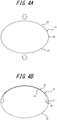
- a container having a body 21 formed into a flattened shape having an oval cross-section is known.
- the body 21 has a front side wall 22 and a rear side wall 23 opposed to each other across a center axis line C in a thickness direction (a short axis direction), and as illustrated by arrows in FIG. 4A , the body 21 can be sandwiched from both sides in the thickness direction and squeezed.
- the present disclosure is to solve the above problem, and is to provide a synthetic resin container having a shape that does not allow a gap to be easily formed therein when a body of a flattened container is squeezed so as to reduce the remaining amount of the contents.
- the disclosed synthetic resin container is a synthetic resin container having a tubular mouth portion and a body connected to the mouth portion and forming a space that contains contents, the body being squeezed to discharge the contents, wherein:
- an angle formed by a tangent to the front side wall starting from a top of the bent portion and a tangent to the rear side wall starting from the top is 140° or less.
- the flatness of the body may preferably be not less than 1.2 and not more than 1.8.
- a contour line of the end on the another side in the axial direction is located inside a semicircular virtual arc that passes through a center point of the end on the another side located on the center axis line and has a maximum thickness of the body as a diameter.
- a contour line of the end on the another side in the axial direction is a substantially semicircular shape with the maximum width of the body as a diameter.
- a synthetic resin container having a shape that does not allow a gap to be easily formed therein when a body of a flattened container is squeezed so as to reduce a remaining amount of the contents can be provided.
- a synthetic resin container 1 (hereinafter also referred to as "container 1") according to the present embodiment illustrated in FIGS. 1 to 3 includes a tubular mouth portion 10 and a body 11 connected to the mouth portion 10 and forming a space S that contains contents.
- the mouth portion 10 is formed into a cylindrical shape and an outer periphery thereof is provided with a male thread 10a to which a cap or the like can be fitted. Further, a top opening 10b of the mouth portion 10 is provided as a discharge port for the contents.
- the body 11 has a flattened shape with the width W larger than the thickness.
- the body 11 has a flexibility and is configured to be able to be squeezed in the thickness (short axis) direction when the contents are discharged.
- the body 11 has a tubular central portion 11a whose cross-sectional shape is constant. Further, an end 11b on one side in the axial direction along the center axis line C of the body 11 is connected to the mouth portion 10, a diameter of the end 11b being gradually decreased from a portion connected to the central portion 11a. Further, a diameter of an end (closed end) 11c on another side in the axial direction of the body 11 is gradually decreased toward the bottom, and is closed at the bottom.
- the closed end 11c entirely swells downward into a curved shape.
- the entire closed end 11c swells downward into a curved shape, and as a result, compared with a container whose lower end of the body is closed by a bottom wall that is vertical to the center axis line, the body 11 is easily squeezed in the thickness direction.
- the body 11 has a front side wall 12 and a rear side wall 13 opposed to each other across the center axis line C in the thickness direction. Further, widthwise ends on both sides of the body 11, that is, a boundary between the front side wall 12 and the rear side wall 13, are respectively provided with bent portions 14 extending in parallel with the axial direction of the body 11.
- the bent portion 14 is configured to be a starting point when the body 11 is squeezed in the thickness direction and one of the front side wall 12 and the rear side wall 13 is inverted and deformed toward the other.
- the bent portion 14 extends linearly along a particle line PL of a mold.
- the particle line PL of the container 1 formed by a division face of the mold is illustrated over the center axis line C.
- the front side wall 12 and the rear side wall 13 of the body 11 When the contents contained in a space S of the container 1 is discharged from the top opening 10b of the mouth portion 10, the front side wall 12 and the rear side wall 13 of the body 11 is sandwiched from both sides so that they are squeezed in the thickness direction.
- the body 11 of the container 1 is squeezed in the thickness direction, as illustrated in FIG. 3B , either one of the front side wall 12 and the rear side wall 13 (the front side wall 12 in the illustrated example) is inverted and deformed toward the other (the rear side wall 13 in the illustrated example).
- the ends on both sides in the width direction of the body 11 can be folded at a sharp angle with the bent portions 14 located on both ends in the width direction as a starting point, which makes it difficult to form a space like a gap G illustrated in FIG. 4B , and as a result the amount of contents remaining in the space S can be reduced.
- the contents remaining in the container increases as the viscosity of the contents in the container increases, which makes it difficult to use up the contents in the container.
- the container 1 according to the present embodiment it is more effective for the container 1 according to the present embodiment to be used for contents with a high viscosity.
- the contour line of the closed end 11c of the body 11 has a substantially semicircular shape with a maximum width W of the body 11 as a diameter.
- the contour line of the closed end 11c of the body 11 is located inside the virtual arc V.
- the virtual arc V is a semicircular arc that passes through a center point 11d of the closed end 11c located on the center axis line C (lower end of the closed end 11c) and has a maximum thickness T of the body 11 as a diameter.
- the center of curvature P of the virtual arc V is located on the center axis line C of the body 11.
- the contour line of the closed end 11c is located inside the virtual arc V, which allows for smoother inversion and deformation when the closed end 11c is squeezed in the thickness direction and easy maintenance of the shape resulting from the inversion and deformation.
- an effect of the present disclosure which is a reduction in the amount of contents remaining in the space S, can be enhanced.
- an angle formed by a tangent L1 to the front side wall 12 starting from a top 14a of the bent portion 14 and a tangent L2 to the rear side wall 13 starting from the top 14a of the bent portion 14 is 140° or less.
- the flatness of the body 11 may preferably be not less than 1.2 and not more than 1.8. With this configuration, the body 11 can be squeezed more smoothly and inverted and deformed, and the shape resulting from the inversion and deformation can be maintained easily. Furthermore, an extreme reduction in volume of the contents in the space S is prevented, and an appropriate amount of contents in the container can be ensured.
- the body 11 has the front side wall 12 and the rear side wall 13 in a shape symmetrical to the plane that passes through the center axis line C and the long axis of the body 11. That is, in this example, the body 11 has a shape symmetrical in the thickness direction (front-back direction). In this manner, when either one of the front side wall 12 and the rear side wall 13 of the body 11 is inverted and deformed toward the other, a gap formed between the front side wall 12 and the rear side wall 13 is reduced, and as a result an amount of the contents remaining in the space S can be further reduced.
- the body 11 is symmetrical about the plane that passes through the center axis line C and the short axis of the body 11. That is, in this example, the body 11 is formed in a shape symmetrical about the width direction (right-left direction). As a result a right and left balance of the body 11 is achieved between right and left, and a failure of squeezing of the body 11 unbalanced between right and left can be suppressed, which allows for an easier squeezing operation of the entire body 11. It is to be noted that the body 11 may be asymmetrical in the front-rear direction and the right-left direction.
- the container 1 can be obtained by the extrusion blow molding in which a tubular parison formed by olefin synthetic resin such as PP, PE (LDPE), for example, is used.
- a pinch-off portion 15 formed by cutoff of a sprit mold for blow molding is provided to the closed end 11c.
- the manufacturing method of the container 1 is not limited thereto, and a variety of methods can be adopted.
- the body 11 is formed into a smoothly curved shape to obtain a substantially oval shape excepting the bent portion 14, a bent portion or recess and protrusion may be provided to the front side wall 12 and the rear side wall 13.
- the container 1 may be provided as a double container having an outer layer body forming an outline of the container and an inner layer body provided inside the outer layer body. In this case, an atmospheric air introduction hole is formed in the mouth portion or the body of the outer layer body to introduce atmospheric air into between the outer layer body and the inner layer body.
- the container 1 when the container 1 is provided as a double container, the container can be formed by the extrusion blow molding in which a tubular parison is used.
- the parison is formed by laminating a synthetic resin forming the outer layer body and a synthetic resin forming the inner layer body that has a low compatibility with the synthetic resin forming the outer layer body.
- the outer layer body may be formed of polypropylene resin (PP) and the inner layer body may be formed of ethylene vinyl alcohol copolymer (EVOH).
- PP polypropylene resin
- EVOH ethylene vinyl alcohol copolymer
- the above described layer configuration is an example, and the materials of the outer layer body and the inner layer body are not limited as far as the inner layer body is separable from the outer layer body.
- Each of the outer layer body and the inner layer body may be provided as a single layer structure, or the inner layer body may have a multi-layer structure formed of multiple layers such as "EVOH/adhesive/olefin,” “nylon/adhesive/olefin” or the like.
Landscapes
- Engineering & Computer Science (AREA)
- Mechanical Engineering (AREA)
- Ceramic Engineering (AREA)
- Containers Having Bodies Formed In One Piece (AREA)
- Tubes (AREA)
Abstract
Description
- The present disclosure relates to a synthetic resin container that includes a tubular mouth portion and a flattened body connected to the mouth portion and discharges contents when the body is squeezed.
- As a container configured to contain a variety of types of contents such as foods and cosmetics, a synthetic resin container including a tubular mouth portion and a body connected to the mouth portion and forming a space configured to contain contents has been known (see, for example, Patent Literature 1).
- Further, examples of a synthetic resin container used for contents having a relatively high viscosity, for example, include those from which contents contained therein are discharged by squeezing a flexible body. In addition, as illustrated in
FIG. 4A , for the purpose of an easy squeezing operation of a container, a container having abody 21 formed into a flattened shape having an oval cross-section is known. Specifically, thebody 21 has afront side wall 22 and arear side wall 23 opposed to each other across a center axis line C in a thickness direction (a short axis direction), and as illustrated by arrows inFIG. 4A , thebody 21 can be sandwiched from both sides in the thickness direction and squeezed. - PTL 1:
JP4137523 B2 - However, in the above described container, when the
body 21 is squeezed and thefront side wall 22 is inverted and deformed toward therear side wall 23, a gap G is formed at awidthwise end 24 of thebody 21 as illustrated inFIG. 4B . Thus contents easily remain in the gap G and it is difficult to use up the contents. - The present disclosure is to solve the above problem, and is to provide a synthetic resin container having a shape that does not allow a gap to be easily formed therein when a body of a flattened container is squeezed so as to reduce the remaining amount of the contents.
- The disclosed synthetic resin container is a synthetic resin container having a tubular mouth portion and a body connected to the mouth portion and forming a space that contains contents, the body being squeezed to discharge the contents, wherein:
- the body has a flattened shape with a width larger than a thickness;
- an end on one side in an axial direction along a center axis line of the body is connected to the mouth portion;
- an end on another side in the axial direction of the body is closed and has a curved shape protruding to the another side in the axial direction;
- widthwise ends on both sides of the body are provided respectively with bent portions extending in parallel with the axial direction; and
- when the body is squeezed in a thickness direction to discharge the contents, the bent portion is a starting point when one of a front side wall and a rear side wall opposed to each other in a thickness direction of the body is inverted and deformed toward the other.
- According to the disclosed synthetic resin container, in a planar view from the axial direction, it is preferable that an angle formed by a tangent to the front side wall starting from a top of the bent portion and a tangent to the rear side wall starting from the top is 140° or less.
- Further, in the disclosed synthetic resin container, the flatness of the body may preferably be not less than 1.2 and not more than 1.8.
- According to the disclosed synthetic resin container, in a side view from an extending direction of a long axis of the body, it is preferable that a contour line of the end on the another side in the axial direction is located inside a semicircular virtual arc that passes through a center point of the end on the another side located on the center axis line and has a maximum thickness of the body as a diameter.
- According to the disclosed synthetic resin container, in a front view from an extending direction of a short axis of the body, it is preferable that a contour line of the end on the another side in the axial direction is a substantially semicircular shape with the maximum width of the body as a diameter.
- According to the present disclosure, a synthetic resin container having a shape that does not allow a gap to be easily formed therein when a body of a flattened container is squeezed so as to reduce a remaining amount of the contents can be provided.
- In the accompanying drawings:
-
FIG. 1 is a front view of a synthetic resin container according to an embodiment of the present disclosure; -
FIG. 2 is a side view of the synthetic resin container inFIG. 1 ; -
FIG. 3A is a plan view of the synthetic resin container inFIG. 1 ; -
FIG. 3B is a cross sectional view along A-A section inFIG. 1 in a state where a body is squeezed; -
FIG. 4A is a cross-sectional view of a body of a flattened container as a comparative example; and -
FIG. 4B is a cross-sectional view of the body of the container inFIG. 4A in a state where the body is squeezed. - The present disclosure will be illustrated in more detail below with reference to the drawings.
- A synthetic resin container 1 (hereinafter also referred to as "
container 1") according to the present embodiment illustrated inFIGS. 1 to 3 includes atubular mouth portion 10 and abody 11 connected to themouth portion 10 and forming a space S that contains contents. In the present embodiment, themouth portion 10 is formed into a cylindrical shape and an outer periphery thereof is provided with amale thread 10a to which a cap or the like can be fitted. Further, a top opening 10b of themouth portion 10 is provided as a discharge port for the contents. - The
body 11 has a flattened shape with the width W larger than the thickness. Thebody 11 has a flexibility and is configured to be able to be squeezed in the thickness (short axis) direction when the contents are discharged. Thebody 11 has a tubularcentral portion 11a whose cross-sectional shape is constant. Further, anend 11b on one side in the axial direction along the center axis line C of thebody 11 is connected to themouth portion 10, a diameter of theend 11b being gradually decreased from a portion connected to thecentral portion 11a. Further, a diameter of an end (closed end) 11c on another side in the axial direction of thebody 11 is gradually decreased toward the bottom, and is closed at the bottom. Thus the closedend 11c entirely swells downward into a curved shape. In this manner, in thecontainer 1 according to the present embodiment, the entire closedend 11c swells downward into a curved shape, and as a result, compared with a container whose lower end of the body is closed by a bottom wall that is vertical to the center axis line, thebody 11 is easily squeezed in the thickness direction. - The
body 11 has afront side wall 12 and arear side wall 13 opposed to each other across the center axis line C in the thickness direction. Further, widthwise ends on both sides of thebody 11, that is, a boundary between thefront side wall 12 and therear side wall 13, are respectively provided withbent portions 14 extending in parallel with the axial direction of thebody 11. Thebent portion 14 is configured to be a starting point when thebody 11 is squeezed in the thickness direction and one of thefront side wall 12 and therear side wall 13 is inverted and deformed toward the other. - In this example, the
bent portion 14 extends linearly along a particle line PL of a mold. In a side view of thecontainer 1 illustrated inFIG. 2 , the particle line PL of thecontainer 1 formed by a division face of the mold is illustrated over the center axis line C. - When the contents contained in a space S of the
container 1 is discharged from the top opening 10b of themouth portion 10, thefront side wall 12 and therear side wall 13 of thebody 11 is sandwiched from both sides so that they are squeezed in the thickness direction. When thebody 11 of thecontainer 1 is squeezed in the thickness direction, as illustrated inFIG. 3B , either one of thefront side wall 12 and the rear side wall 13 (thefront side wall 12 in the illustrated example) is inverted and deformed toward the other (therear side wall 13 in the illustrated example). Further, when inverted and deformed, the ends on both sides in the width direction of thebody 11 can be folded at a sharp angle with thebent portions 14 located on both ends in the width direction as a starting point, which makes it difficult to form a space like a gap G illustrated inFIG. 4B , and as a result the amount of contents remaining in the space S can be reduced. In particular, the contents remaining in the container increases as the viscosity of the contents in the container increases, which makes it difficult to use up the contents in the container. Thus it is more effective for thecontainer 1 according to the present embodiment to be used for contents with a high viscosity. - According to the
container 1 of the present embodiment, in a front view from the extending direction (thickness direction) of the short axis of thebody 11 as illustrated inFIG. 1 , the contour line of theclosed end 11c of thebody 11 has a substantially semicircular shape with a maximum width W of thebody 11 as a diameter. In this manner, smoother inversion and deformation is possible when theclosed end 11c is squeezed in the thickness direction, and the shape resulting from the inversion and deformation can be maintained easily. As a result, an effect of the present disclosure, which is a reduction in the amount of contents remaining in the space S, can be enhanced. - As illustrated in
FIG. 2 , in a side view from the extending direction of the long axis of thebody 11, the contour line of theclosed end 11c of thebody 11 is located inside the virtual arc V. The virtual arc V is a semicircular arc that passes through acenter point 11d of theclosed end 11c located on the center axis line C (lower end of theclosed end 11c) and has a maximum thickness T of thebody 11 as a diameter. The center of curvature P of the virtual arc V is located on the center axis line C of thebody 11. In this manner, the contour line of theclosed end 11c is located inside the virtual arc V, which allows for smoother inversion and deformation when theclosed end 11c is squeezed in the thickness direction and easy maintenance of the shape resulting from the inversion and deformation. As a result, an effect of the present disclosure, which is a reduction in the amount of contents remaining in the space S, can be enhanced. - As illustrated in
FIG. 3A , in a plan view from the axial direction of thecontainer 1, it is preferable that an angle formed by a tangent L1 to thefront side wall 12 starting from a top 14a of thebent portion 14 and a tangent L2 to therear side wall 13 starting from the top 14a of thebent portion 14 is 140° or less. The above described configuration allows for smoother inversion and deformation of thebody 11 and easy maintenance of the shape resulting from the inversion and deformation. As a result, an effect of the present disclosure, which is a reduction in the amount of contents contained in the space S, can be enhanced. - The flatness of the
body 11 may preferably be not less than 1.2 and not more than 1.8. With this configuration, thebody 11 can be squeezed more smoothly and inverted and deformed, and the shape resulting from the inversion and deformation can be maintained easily. Furthermore, an extreme reduction in volume of the contents in the space S is prevented, and an appropriate amount of contents in the container can be ensured. In this context, the flatness of thebody 11 is a value represented by a ratio of the maximum width W of thebody 11 to the maximum thickness T of thebody 11. That is, the flatness is a value resulting from the equation of flatness = W/T. In this example, the maximum thickness of thebody 11 is 47 mm and the maximum width of thebody 11 is 71 mm. Thus the flatness is 1.51. - In this example, the
body 11 has thefront side wall 12 and therear side wall 13 in a shape symmetrical to the plane that passes through the center axis line C and the long axis of thebody 11. That is, in this example, thebody 11 has a shape symmetrical in the thickness direction (front-back direction). In this manner, when either one of thefront side wall 12 and therear side wall 13 of thebody 11 is inverted and deformed toward the other, a gap formed between thefront side wall 12 and therear side wall 13 is reduced, and as a result an amount of the contents remaining in the space S can be further reduced. - Further, in this example, the
body 11 is symmetrical about the plane that passes through the center axis line C and the short axis of thebody 11. That is, in this example, thebody 11 is formed in a shape symmetrical about the width direction (right-left direction). As a result a right and left balance of thebody 11 is achieved between right and left, and a failure of squeezing of thebody 11 unbalanced between right and left can be suppressed, which allows for an easier squeezing operation of theentire body 11. It is to be noted that thebody 11 may be asymmetrical in the front-rear direction and the right-left direction. - The
container 1 can be obtained by the extrusion blow molding in which a tubular parison formed by olefin synthetic resin such as PP, PE (LDPE), for example, is used. In this example, a pinch-off portion 15 formed by cutoff of a sprit mold for blow molding is provided to theclosed end 11c. It is to be noted the manufacturing method of thecontainer 1 is not limited thereto, and a variety of methods can be adopted. - The above description is merely an embodiment of the present disclosure, and various changes may be made to the claims. For example, in the above described embodiment, although the
body 11 is formed into a smoothly curved shape to obtain a substantially oval shape excepting thebent portion 14, a bent portion or recess and protrusion may be provided to thefront side wall 12 and therear side wall 13. Further, thecontainer 1 may be provided as a double container having an outer layer body forming an outline of the container and an inner layer body provided inside the outer layer body. In this case, an atmospheric air introduction hole is formed in the mouth portion or the body of the outer layer body to introduce atmospheric air into between the outer layer body and the inner layer body. Further, when thecontainer 1 is provided as a double container, the container can be formed by the extrusion blow molding in which a tubular parison is used. The parison is formed by laminating a synthetic resin forming the outer layer body and a synthetic resin forming the inner layer body that has a low compatibility with the synthetic resin forming the outer layer body. In that case, for example, the outer layer body may be formed of polypropylene resin (PP) and the inner layer body may be formed of ethylene vinyl alcohol copolymer (EVOH). The above described layer configuration is an example, and the materials of the outer layer body and the inner layer body are not limited as far as the inner layer body is separable from the outer layer body. Each of the outer layer body and the inner layer body may be provided as a single layer structure, or the inner layer body may have a multi-layer structure formed of multiple layers such as "EVOH/adhesive/olefin," "nylon/adhesive/olefin" or the like. -
- 1 synthetic resin container
- 10 mouth portion
- 11 body
- 11a central portion of the body
- 11b end on one side in the axial direction of the body
- 11c end (closed end) on the other side in the axial direction of the body
- 12 front side wall
- 13 rear side wall
- 14 bent portion
- C center axis line
- S space
Claims (5)
- A synthetic resin container comprising a tubular mouth portion and a body connected to the mouth portion and forming a space that contains contents, the body being squeezed to discharge the contents, wherein,
the body has a flattened shape with a width larger than a thickness;
an end on one side in an axial direction along a center axis line of the body is connected to the mouth portion;
an end on another side in the axial direction of the body is closed and has a curved shape protruding to the another side in the axial direction;
widthwise ends on both sides of the body are provided respectively with bent portions extending in parallel with the axial direction; and
when the body is squeezed in a thickness direction to discharge the contents, the bent portion is configured to be a starting point when one of a front side wall and a rear side wall opposed to each other in the thickness direction of the body is inverted and deformed toward the other. - The synthetic resin container according to claim 1, wherein, in a planar view from the axial direction, an angle formed by a tangent to the front side wall starting from a top of the bent portion and a tangent to the rear side wall starting from the top is 140° or less.
- The synthetic resin container according to claim 1 or 2, wherein a flatness of the body is not less than 1.2 and not more than 1.8.
- The synthetic resin container according to any one of claims 1 to 3, wherein, in a side view from an extending direction of a long axis of the body, a contour line of the end on the another side in the axial direction is located inside a semicircular virtual arc that passes through a center point of the end on the another side located on the center axis line and has a maximum thickness of the body as a diameter.
- The synthetic resin container according to any one of claims 1 to 4, wherein, in a front view from an extending direction of a short axis of the body, a contour line of the end on the another side in the axial direction is a substantially semicircular with a maximum width of the body as a diameter.
Applications Claiming Priority (2)
| Application Number | Priority Date | Filing Date | Title |
|---|---|---|---|
| JP2017108187A JP6855126B2 (en) | 2017-05-31 | 2017-05-31 | Synthetic resin container |
| PCT/JP2018/009986 WO2018220944A1 (en) | 2017-05-31 | 2018-03-14 | Synthetic resin container |
Publications (3)
| Publication Number | Publication Date |
|---|---|
| EP3632811A1 true EP3632811A1 (en) | 2020-04-08 |
| EP3632811A4 EP3632811A4 (en) | 2021-03-31 |
| EP3632811B1 EP3632811B1 (en) | 2023-12-13 |
Family
ID=64454651
Family Applications (1)
| Application Number | Title | Priority Date | Filing Date |
|---|---|---|---|
| EP18809339.7A Active EP3632811B1 (en) | 2017-05-31 | 2018-03-14 | Synthetic resin container |
Country Status (4)
| Country | Link |
|---|---|
| US (1) | US11097871B2 (en) |
| EP (1) | EP3632811B1 (en) |
| JP (1) | JP6855126B2 (en) |
| WO (1) | WO2018220944A1 (en) |
Families Citing this family (4)
| Publication number | Priority date | Publication date | Assignee | Title |
|---|---|---|---|---|
| JP7295393B2 (en) * | 2019-03-27 | 2023-06-21 | キョーラク株式会社 | delaminating container |
| USD898575S1 (en) * | 2019-04-04 | 2020-10-13 | Societe Anonyme Des Eaux Minerales D'evian | Bottle for water dispensers |
| JP2021070504A (en) * | 2019-10-31 | 2021-05-06 | 小林製薬株式会社 | Squeeze container |
| JP7504538B2 (en) * | 2019-12-26 | 2024-06-24 | 株式会社吉野工業所 | Plastic flat container |
Family Cites Families (38)
| Publication number | Priority date | Publication date | Assignee | Title |
|---|---|---|---|---|
| US3229014A (en) * | 1962-05-31 | 1966-01-11 | Dilectrix Corp | Methods of making a flexible container |
| US3213913A (en) * | 1962-05-31 | 1965-10-26 | Dilectrix Corp | Flexible containers |
| CH557178A (en) * | 1972-08-10 | 1974-12-31 | Siemens Ag | DEVICE FOR DISPENSING DRUGS. |
| US4034896A (en) * | 1975-12-18 | 1977-07-12 | Wilson Walon K | Diaphragm controlled garden and orchard sprayer |
| JPS5498438U (en) * | 1977-12-22 | 1979-07-11 | ||
| US4252257A (en) * | 1978-10-10 | 1981-02-24 | Herzig Albert M | Automatic closure for containers having a pinch-off fold |
| US4232721A (en) * | 1979-04-09 | 1980-11-11 | Baxter Travenol Laboratories, Inc. | Collapsible solution container having rectangular shoulder |
| US4486379A (en) * | 1980-03-26 | 1984-12-04 | W. R. Grace & Co., Cryovac Div. | Process for forming an integral hinged single wall blow molded container |
| DE3844090A1 (en) | 1988-12-28 | 1990-07-12 | Benckiser Gmbh Joh A | STOCK BOTTLE FOR HOUSEHOLD LIQUIDS |
| ES2038021T5 (en) * | 1989-07-20 | 1998-02-16 | During Ag | FOLDING PLASTIC BOTTLE. |
| JP2931985B2 (en) * | 1989-08-30 | 1999-08-09 | 株式会社吉野工業所 | Blow-molded bottle made of synthetic resin and molding method |
| JP3049562B2 (en) * | 1990-06-13 | 2000-06-05 | 佳久 小川 | Tubular container |
| US5090963A (en) * | 1990-10-19 | 1992-02-25 | Product Development (Z.G.S.) Ltd. | Electrochemically driven metering medicament dispenser |
| US5242406A (en) * | 1990-10-19 | 1993-09-07 | Sil Medics Ltd. | Liquid delivery device particularly useful for delivering drugs |
| US5301840A (en) * | 1991-04-08 | 1994-04-12 | Colgate-Palmolive Company | Tube dispenser capable of creating a suckback effect in the nozzle |
| US5261565A (en) * | 1992-06-11 | 1993-11-16 | The Procter & Gamble Company | Thin film beam spring vent valve |
| GB2273485B (en) | 1992-12-17 | 1996-01-31 | Lawson Mardon Group Uk Ltd | Collapsible containers |
| JP2666719B2 (en) | 1994-03-31 | 1997-10-22 | 東洋製罐株式会社 | Foldable blow molded bottle |
| US5810202A (en) * | 1994-10-20 | 1998-09-22 | Rick R. Wascher, P.C. | Disposable self-dispensing pressurized package for delivery of sterile fluids and solutions |
| SE508438C2 (en) * | 1995-03-31 | 1998-10-05 | Norden Pac Dev Ab | packaging Containers |
| JPH107121A (en) | 1996-06-21 | 1998-01-13 | Shiseido Co Ltd | Container with cap |
| US5954224A (en) | 1996-11-01 | 1999-09-21 | Colgate-Palmolive Company | Injection stretch blow molded tubular containers |
| JP3750012B2 (en) * | 1999-05-10 | 2006-03-01 | 忠 萩原 | Fluid container nozzle and fluid container provided with the same |
| USD451809S1 (en) * | 1999-11-22 | 2001-12-11 | Fwj Plastic Packaging, Inc. | Bottle |
| JP3994145B2 (en) * | 2001-08-31 | 2007-10-17 | 株式会社吉野工業所 | Dispensing container |
| JP4137523B2 (en) | 2002-05-29 | 2008-08-20 | 株式会社吉野工業所 | Synthetic resin bottle type container |
| WO2004020296A1 (en) * | 2002-08-28 | 2004-03-11 | Yoshino Kogyosho Co., Ltd | Synthetic resin bottle |
| USD489266S1 (en) * | 2002-11-06 | 2004-05-04 | Hawthorn Enterprise Co., Ltd. | Cosmetic bottle |
| USD485764S1 (en) * | 2002-11-12 | 2004-01-27 | Db Design Gmbh | Bottle |
| US7445131B2 (en) * | 2004-08-26 | 2008-11-04 | Susan Pottish | Apparatus and method for reusable, no-waste collapsible tube dispensers |
| JP5124085B2 (en) * | 2005-08-24 | 2013-01-23 | 押尾産業株式会社 | Self-supporting bag and its manufacturing method |
| JP5007742B2 (en) * | 2006-06-01 | 2012-08-22 | イー・アイ・デュポン・ドウ・ヌムール・アンド・カンパニー | Multi-chamber pouch with fragile seal |
| EP2669214B1 (en) * | 2009-07-09 | 2016-01-20 | Advanced Technology Materials, Inc. | Storage system with a blow molded collapsible liner |
| US8910673B2 (en) * | 2009-12-25 | 2014-12-16 | Yoshino Kogyosho Co., Ltd. | Synthetic resin bottle, and a combination of regularly used container and refill container |
| US20150108015A1 (en) * | 2013-10-17 | 2015-04-23 | Pouch Pac Innovations, Llc | Pouch with absorbent liner and method of forming |
| US10059604B2 (en) * | 2014-08-01 | 2018-08-28 | QuenchWorks, LLC | Roll-up water bottle with closure/filter assembly |
| JP6516122B2 (en) * | 2014-08-19 | 2019-05-22 | 株式会社平和化学工業所 | Method of manufacturing double container |
| WO2020113217A1 (en) * | 2018-11-30 | 2020-06-04 | Scholle Ipn Corporation | Squeeze-out pouch |
-
2017
- 2017-05-31 JP JP2017108187A patent/JP6855126B2/en active Active
-
2018
- 2018-03-14 WO PCT/JP2018/009986 patent/WO2018220944A1/en not_active Ceased
- 2018-03-14 US US16/609,730 patent/US11097871B2/en active Active
- 2018-03-14 EP EP18809339.7A patent/EP3632811B1/en active Active
Also Published As
| Publication number | Publication date |
|---|---|
| WO2018220944A1 (en) | 2018-12-06 |
| EP3632811B1 (en) | 2023-12-13 |
| JP2018203296A (en) | 2018-12-27 |
| JP6855126B2 (en) | 2021-04-07 |
| US11097871B2 (en) | 2021-08-24 |
| US20200062457A1 (en) | 2020-02-27 |
| EP3632811A4 (en) | 2021-03-31 |
Similar Documents
| Publication | Publication Date | Title |
|---|---|---|
| US11097871B2 (en) | Synthetic resin container | |
| CA2889206C (en) | Double container | |
| CN107207114B (en) | Double container | |
| JP2014091537A (en) | Delamination container | |
| CN111511648B (en) | Synthetic resin container | |
| WO2021049236A1 (en) | Delamination container | |
| JP7706867B2 (en) | Delaminated container | |
| JP6489851B2 (en) | Double container | |
| JP7139057B2 (en) | delaminating container | |
| JP7154691B2 (en) | squeeze container | |
| JP2014091580A (en) | Delamination container | |
| JP2019018892A (en) | Synthetic resin-made multiple bottle | |
| JP2021054447A (en) | Lamination peeling container | |
| JP4182520B2 (en) | Dispensing container | |
| JP5992294B2 (en) | Blow molding container | |
| JP2019018893A (en) | Synthetic resin multiple bottles | |
| JP7090977B2 (en) | Laminated peeling container | |
| JP2014091581A (en) | Delamination container | |
| JP7246946B2 (en) | delaminating container | |
| JP2017095129A (en) | Squeeze container | |
| JP2019081560A (en) | Flat container of synthetic resin | |
| JP2019081559A (en) | Flat container of synthetic resin | |
| JP5637591B2 (en) | Blow molding container | |
| JP2019055788A (en) | Squeeze bottle | |
| US20230264848A1 (en) | Double container |
Legal Events
| Date | Code | Title | Description |
|---|---|---|---|
| STAA | Information on the status of an ep patent application or granted ep patent |
Free format text: STATUS: THE INTERNATIONAL PUBLICATION HAS BEEN MADE |
|
| PUAI | Public reference made under article 153(3) epc to a published international application that has entered the european phase |
Free format text: ORIGINAL CODE: 0009012 |
|
| STAA | Information on the status of an ep patent application or granted ep patent |
Free format text: STATUS: REQUEST FOR EXAMINATION WAS MADE |
|
| 17P | Request for examination filed |
Effective date: 20191104 |
|
| AK | Designated contracting states |
Kind code of ref document: A1 Designated state(s): AL AT BE BG CH CY CZ DE DK EE ES FI FR GB GR HR HU IE IS IT LI LT LU LV MC MK MT NL NO PL PT RO RS SE SI SK SM TR |
|
| AX | Request for extension of the european patent |
Extension state: BA ME |
|
| DAV | Request for validation of the european patent (deleted) | ||
| DAX | Request for extension of the european patent (deleted) | ||
| A4 | Supplementary search report drawn up and despatched |
Effective date: 20210226 |
|
| RIC1 | Information provided on ipc code assigned before grant |
Ipc: B65D 35/08 20060101ALI20210222BHEP Ipc: B65D 35/02 20060101AFI20210222BHEP Ipc: B65D 1/32 20060101ALI20210222BHEP Ipc: B65D 1/02 20060101ALI20210222BHEP |
|
| STAA | Information on the status of an ep patent application or granted ep patent |
Free format text: STATUS: EXAMINATION IS IN PROGRESS |
|
| 17Q | First examination report despatched |
Effective date: 20220531 |
|
| GRAP | Despatch of communication of intention to grant a patent |
Free format text: ORIGINAL CODE: EPIDOSNIGR1 |
|
| STAA | Information on the status of an ep patent application or granted ep patent |
Free format text: STATUS: GRANT OF PATENT IS INTENDED |
|
| INTG | Intention to grant announced |
Effective date: 20230808 |
|
| GRAS | Grant fee paid |
Free format text: ORIGINAL CODE: EPIDOSNIGR3 |
|
| GRAA | (expected) grant |
Free format text: ORIGINAL CODE: 0009210 |
|
| STAA | Information on the status of an ep patent application or granted ep patent |
Free format text: STATUS: THE PATENT HAS BEEN GRANTED |
|
| AK | Designated contracting states |
Kind code of ref document: B1 Designated state(s): AL AT BE BG CH CY CZ DE DK EE ES FI FR GB GR HR HU IE IS IT LI LT LU LV MC MK MT NL NO PL PT RO RS SE SI SK SM TR |
|
| REG | Reference to a national code |
Ref country code: GB Ref legal event code: FG4D |
|
| REG | Reference to a national code |
Ref country code: CH Ref legal event code: EP |
|
| REG | Reference to a national code |
Ref country code: DE Ref legal event code: R096 Ref document number: 602018062675 Country of ref document: DE |
|
| REG | Reference to a national code |
Ref country code: IE Ref legal event code: FG4D |
|
| PG25 | Lapsed in a contracting state [announced via postgrant information from national office to epo] |
Ref country code: GR Free format text: LAPSE BECAUSE OF FAILURE TO SUBMIT A TRANSLATION OF THE DESCRIPTION OR TO PAY THE FEE WITHIN THE PRESCRIBED TIME-LIMIT Effective date: 20240314 |
|
| REG | Reference to a national code |
Ref country code: LT Ref legal event code: MG9D |
|
| PG25 | Lapsed in a contracting state [announced via postgrant information from national office to epo] |
Ref country code: LT Free format text: LAPSE BECAUSE OF FAILURE TO SUBMIT A TRANSLATION OF THE DESCRIPTION OR TO PAY THE FEE WITHIN THE PRESCRIBED TIME-LIMIT Effective date: 20231213 |
|
| REG | Reference to a national code |
Ref country code: NL Ref legal event code: MP Effective date: 20231213 |
|
| PG25 | Lapsed in a contracting state [announced via postgrant information from national office to epo] |
Ref country code: ES Free format text: LAPSE BECAUSE OF FAILURE TO SUBMIT A TRANSLATION OF THE DESCRIPTION OR TO PAY THE FEE WITHIN THE PRESCRIBED TIME-LIMIT Effective date: 20231213 |
|
| PG25 | Lapsed in a contracting state [announced via postgrant information from national office to epo] |
Ref country code: LT Free format text: LAPSE BECAUSE OF FAILURE TO SUBMIT A TRANSLATION OF THE DESCRIPTION OR TO PAY THE FEE WITHIN THE PRESCRIBED TIME-LIMIT Effective date: 20231213 Ref country code: GR Free format text: LAPSE BECAUSE OF FAILURE TO SUBMIT A TRANSLATION OF THE DESCRIPTION OR TO PAY THE FEE WITHIN THE PRESCRIBED TIME-LIMIT Effective date: 20240314 Ref country code: ES Free format text: LAPSE BECAUSE OF FAILURE TO SUBMIT A TRANSLATION OF THE DESCRIPTION OR TO PAY THE FEE WITHIN THE PRESCRIBED TIME-LIMIT Effective date: 20231213 Ref country code: BG Free format text: LAPSE BECAUSE OF FAILURE TO SUBMIT A TRANSLATION OF THE DESCRIPTION OR TO PAY THE FEE WITHIN THE PRESCRIBED TIME-LIMIT Effective date: 20240313 |
|
| REG | Reference to a national code |
Ref country code: AT Ref legal event code: MK05 Ref document number: 1640278 Country of ref document: AT Kind code of ref document: T Effective date: 20231213 |
|
| PG25 | Lapsed in a contracting state [announced via postgrant information from national office to epo] |
Ref country code: NL Free format text: LAPSE BECAUSE OF FAILURE TO SUBMIT A TRANSLATION OF THE DESCRIPTION OR TO PAY THE FEE WITHIN THE PRESCRIBED TIME-LIMIT Effective date: 20231213 |
|
| PG25 | Lapsed in a contracting state [announced via postgrant information from national office to epo] |
Ref country code: SE Free format text: LAPSE BECAUSE OF FAILURE TO SUBMIT A TRANSLATION OF THE DESCRIPTION OR TO PAY THE FEE WITHIN THE PRESCRIBED TIME-LIMIT Effective date: 20231213 Ref country code: RS Free format text: LAPSE BECAUSE OF FAILURE TO SUBMIT A TRANSLATION OF THE DESCRIPTION OR TO PAY THE FEE WITHIN THE PRESCRIBED TIME-LIMIT Effective date: 20231213 Ref country code: NO Free format text: LAPSE BECAUSE OF FAILURE TO SUBMIT A TRANSLATION OF THE DESCRIPTION OR TO PAY THE FEE WITHIN THE PRESCRIBED TIME-LIMIT Effective date: 20240313 Ref country code: NL Free format text: LAPSE BECAUSE OF FAILURE TO SUBMIT A TRANSLATION OF THE DESCRIPTION OR TO PAY THE FEE WITHIN THE PRESCRIBED TIME-LIMIT Effective date: 20231213 Ref country code: LV Free format text: LAPSE BECAUSE OF FAILURE TO SUBMIT A TRANSLATION OF THE DESCRIPTION OR TO PAY THE FEE WITHIN THE PRESCRIBED TIME-LIMIT Effective date: 20231213 Ref country code: HR Free format text: LAPSE BECAUSE OF FAILURE TO SUBMIT A TRANSLATION OF THE DESCRIPTION OR TO PAY THE FEE WITHIN THE PRESCRIBED TIME-LIMIT Effective date: 20231213 |
|
| PG25 | Lapsed in a contracting state [announced via postgrant information from national office to epo] |
Ref country code: IS Free format text: LAPSE BECAUSE OF FAILURE TO SUBMIT A TRANSLATION OF THE DESCRIPTION OR TO PAY THE FEE WITHIN THE PRESCRIBED TIME-LIMIT Effective date: 20240413 |
|
| PG25 | Lapsed in a contracting state [announced via postgrant information from national office to epo] |
Ref country code: AT Free format text: LAPSE BECAUSE OF FAILURE TO SUBMIT A TRANSLATION OF THE DESCRIPTION OR TO PAY THE FEE WITHIN THE PRESCRIBED TIME-LIMIT Effective date: 20231213 Ref country code: CZ Free format text: LAPSE BECAUSE OF FAILURE TO SUBMIT A TRANSLATION OF THE DESCRIPTION OR TO PAY THE FEE WITHIN THE PRESCRIBED TIME-LIMIT Effective date: 20231213 |
|
| PG25 | Lapsed in a contracting state [announced via postgrant information from national office to epo] |
Ref country code: SK Free format text: LAPSE BECAUSE OF FAILURE TO SUBMIT A TRANSLATION OF THE DESCRIPTION OR TO PAY THE FEE WITHIN THE PRESCRIBED TIME-LIMIT Effective date: 20231213 |
|
| PG25 | Lapsed in a contracting state [announced via postgrant information from national office to epo] |
Ref country code: SM Free format text: LAPSE BECAUSE OF FAILURE TO SUBMIT A TRANSLATION OF THE DESCRIPTION OR TO PAY THE FEE WITHIN THE PRESCRIBED TIME-LIMIT Effective date: 20231213 Ref country code: SK Free format text: LAPSE BECAUSE OF FAILURE TO SUBMIT A TRANSLATION OF THE DESCRIPTION OR TO PAY THE FEE WITHIN THE PRESCRIBED TIME-LIMIT Effective date: 20231213 Ref country code: RO Free format text: LAPSE BECAUSE OF FAILURE TO SUBMIT A TRANSLATION OF THE DESCRIPTION OR TO PAY THE FEE WITHIN THE PRESCRIBED TIME-LIMIT Effective date: 20231213 Ref country code: IT Free format text: LAPSE BECAUSE OF FAILURE TO SUBMIT A TRANSLATION OF THE DESCRIPTION OR TO PAY THE FEE WITHIN THE PRESCRIBED TIME-LIMIT Effective date: 20231213 Ref country code: IS Free format text: LAPSE BECAUSE OF FAILURE TO SUBMIT A TRANSLATION OF THE DESCRIPTION OR TO PAY THE FEE WITHIN THE PRESCRIBED TIME-LIMIT Effective date: 20240413 Ref country code: EE Free format text: LAPSE BECAUSE OF FAILURE TO SUBMIT A TRANSLATION OF THE DESCRIPTION OR TO PAY THE FEE WITHIN THE PRESCRIBED TIME-LIMIT Effective date: 20231213 Ref country code: CZ Free format text: LAPSE BECAUSE OF FAILURE TO SUBMIT A TRANSLATION OF THE DESCRIPTION OR TO PAY THE FEE WITHIN THE PRESCRIBED TIME-LIMIT Effective date: 20231213 Ref country code: AT Free format text: LAPSE BECAUSE OF FAILURE TO SUBMIT A TRANSLATION OF THE DESCRIPTION OR TO PAY THE FEE WITHIN THE PRESCRIBED TIME-LIMIT Effective date: 20231213 |
|
| PG25 | Lapsed in a contracting state [announced via postgrant information from national office to epo] |
Ref country code: PL Free format text: LAPSE BECAUSE OF FAILURE TO SUBMIT A TRANSLATION OF THE DESCRIPTION OR TO PAY THE FEE WITHIN THE PRESCRIBED TIME-LIMIT Effective date: 20231213 Ref country code: PT Free format text: LAPSE BECAUSE OF FAILURE TO SUBMIT A TRANSLATION OF THE DESCRIPTION OR TO PAY THE FEE WITHIN THE PRESCRIBED TIME-LIMIT Effective date: 20240415 |
|
| PG25 | Lapsed in a contracting state [announced via postgrant information from national office to epo] |
Ref country code: PT Free format text: LAPSE BECAUSE OF FAILURE TO SUBMIT A TRANSLATION OF THE DESCRIPTION OR TO PAY THE FEE WITHIN THE PRESCRIBED TIME-LIMIT Effective date: 20240415 Ref country code: PL Free format text: LAPSE BECAUSE OF FAILURE TO SUBMIT A TRANSLATION OF THE DESCRIPTION OR TO PAY THE FEE WITHIN THE PRESCRIBED TIME-LIMIT Effective date: 20231213 |
|
| REG | Reference to a national code |
Ref country code: DE Ref legal event code: R097 Ref document number: 602018062675 Country of ref document: DE |
|
| PG25 | Lapsed in a contracting state [announced via postgrant information from national office to epo] |
Ref country code: DK Free format text: LAPSE BECAUSE OF FAILURE TO SUBMIT A TRANSLATION OF THE DESCRIPTION OR TO PAY THE FEE WITHIN THE PRESCRIBED TIME-LIMIT Effective date: 20231213 |
|
| PLBE | No opposition filed within time limit |
Free format text: ORIGINAL CODE: 0009261 |
|
| STAA | Information on the status of an ep patent application or granted ep patent |
Free format text: STATUS: NO OPPOSITION FILED WITHIN TIME LIMIT |
|
| PG25 | Lapsed in a contracting state [announced via postgrant information from national office to epo] |
Ref country code: SI Free format text: LAPSE BECAUSE OF FAILURE TO SUBMIT A TRANSLATION OF THE DESCRIPTION OR TO PAY THE FEE WITHIN THE PRESCRIBED TIME-LIMIT Effective date: 20231213 |
|
| PG25 | Lapsed in a contracting state [announced via postgrant information from national office to epo] |
Ref country code: SI Free format text: LAPSE BECAUSE OF FAILURE TO SUBMIT A TRANSLATION OF THE DESCRIPTION OR TO PAY THE FEE WITHIN THE PRESCRIBED TIME-LIMIT Effective date: 20231213 Ref country code: DK Free format text: LAPSE BECAUSE OF FAILURE TO SUBMIT A TRANSLATION OF THE DESCRIPTION OR TO PAY THE FEE WITHIN THE PRESCRIBED TIME-LIMIT Effective date: 20231213 |
|
| REG | Reference to a national code |
Ref country code: CH Ref legal event code: PL |
|
| PG25 | Lapsed in a contracting state [announced via postgrant information from national office to epo] |
Ref country code: LU Free format text: LAPSE BECAUSE OF NON-PAYMENT OF DUE FEES Effective date: 20240314 |
|
| 26N | No opposition filed |
Effective date: 20240916 |
|
| PG25 | Lapsed in a contracting state [announced via postgrant information from national office to epo] |
Ref country code: MC Free format text: LAPSE BECAUSE OF FAILURE TO SUBMIT A TRANSLATION OF THE DESCRIPTION OR TO PAY THE FEE WITHIN THE PRESCRIBED TIME-LIMIT Effective date: 20231213 |
|
| PG25 | Lapsed in a contracting state [announced via postgrant information from national office to epo] |
Ref country code: MC Free format text: LAPSE BECAUSE OF FAILURE TO SUBMIT A TRANSLATION OF THE DESCRIPTION OR TO PAY THE FEE WITHIN THE PRESCRIBED TIME-LIMIT Effective date: 20231213 Ref country code: LU Free format text: LAPSE BECAUSE OF NON-PAYMENT OF DUE FEES Effective date: 20240314 |
|
| REG | Reference to a national code |
Ref country code: BE Ref legal event code: MM Effective date: 20240331 |
|
| PG25 | Lapsed in a contracting state [announced via postgrant information from national office to epo] |
Ref country code: BE Free format text: LAPSE BECAUSE OF NON-PAYMENT OF DUE FEES Effective date: 20240331 |
|
| PG25 | Lapsed in a contracting state [announced via postgrant information from national office to epo] |
Ref country code: IE Free format text: LAPSE BECAUSE OF NON-PAYMENT OF DUE FEES Effective date: 20240314 |
|
| PG25 | Lapsed in a contracting state [announced via postgrant information from national office to epo] |
Ref country code: IE Free format text: LAPSE BECAUSE OF NON-PAYMENT OF DUE FEES Effective date: 20240314 Ref country code: BE Free format text: LAPSE BECAUSE OF NON-PAYMENT OF DUE FEES Effective date: 20240331 Ref country code: CH Free format text: LAPSE BECAUSE OF NON-PAYMENT OF DUE FEES Effective date: 20240331 |
|
| PG25 | Lapsed in a contracting state [announced via postgrant information from national office to epo] |
Ref country code: CY Free format text: LAPSE BECAUSE OF FAILURE TO SUBMIT A TRANSLATION OF THE DESCRIPTION OR TO PAY THE FEE WITHIN THE PRESCRIBED TIME-LIMIT; INVALID AB INITIO Effective date: 20180314 |
|
| PG25 | Lapsed in a contracting state [announced via postgrant information from national office to epo] |
Ref country code: HU Free format text: LAPSE BECAUSE OF FAILURE TO SUBMIT A TRANSLATION OF THE DESCRIPTION OR TO PAY THE FEE WITHIN THE PRESCRIBED TIME-LIMIT; INVALID AB INITIO Effective date: 20180314 |
|
| PG25 | Lapsed in a contracting state [announced via postgrant information from national office to epo] |
Ref country code: FI Free format text: LAPSE BECAUSE OF FAILURE TO SUBMIT A TRANSLATION OF THE DESCRIPTION OR TO PAY THE FEE WITHIN THE PRESCRIBED TIME-LIMIT Effective date: 20231213 |
|
| PG25 | Lapsed in a contracting state [announced via postgrant information from national office to epo] |
Ref country code: TR Free format text: LAPSE BECAUSE OF FAILURE TO SUBMIT A TRANSLATION OF THE DESCRIPTION OR TO PAY THE FEE WITHIN THE PRESCRIBED TIME-LIMIT Effective date: 20231213 |
|
| PGFP | Annual fee paid to national office [announced via postgrant information from national office to epo] |
Ref country code: GB Payment date: 20260202 Year of fee payment: 9 |
|
| PGFP | Annual fee paid to national office [announced via postgrant information from national office to epo] |
Ref country code: DE Payment date: 20260128 Year of fee payment: 9 |
|
| PGFP | Annual fee paid to national office [announced via postgrant information from national office to epo] |
Ref country code: FR Payment date: 20260209 Year of fee payment: 9 |