EP3632783A1 - Saddle-type vehicle control apparatus - Google Patents
Saddle-type vehicle control apparatus Download PDFInfo
- Publication number
- EP3632783A1 EP3632783A1 EP18805425.8A EP18805425A EP3632783A1 EP 3632783 A1 EP3632783 A1 EP 3632783A1 EP 18805425 A EP18805425 A EP 18805425A EP 3632783 A1 EP3632783 A1 EP 3632783A1
- Authority
- EP
- European Patent Office
- Prior art keywords
- vehicle
- section
- rider
- straddle
- control apparatus
- Prior art date
- Legal status (The legal status is an assumption and is not a legal conclusion. Google has not performed a legal analysis and makes no representation as to the accuracy of the status listed.)
- Granted
Links
Images


Classifications
-
- B—PERFORMING OPERATIONS; TRANSPORTING
- B62—LAND VEHICLES FOR TRAVELLING OTHERWISE THAN ON RAILS
- B62J—CYCLE SADDLES OR SEATS; AUXILIARY DEVICES OR ACCESSORIES SPECIALLY ADAPTED TO CYCLES AND NOT OTHERWISE PROVIDED FOR, e.g. ARTICLE CARRIERS OR CYCLE PROTECTORS
- B62J50/00—Arrangements specially adapted for use on cycles not provided for in main groups B62J1/00 - B62J45/00
- B62J50/20—Information-providing devices
- B62J50/21—Information-providing devices intended to provide information to rider or passenger
- B62J50/22—Information-providing devices intended to provide information to rider or passenger electronic, e.g. displays
-
- B—PERFORMING OPERATIONS; TRANSPORTING
- B60—VEHICLES IN GENERAL
- B60K—ARRANGEMENT OR MOUNTING OF PROPULSION UNITS OR OF TRANSMISSIONS IN VEHICLES; ARRANGEMENT OR MOUNTING OF PLURAL DIVERSE PRIME-MOVERS IN VEHICLES; AUXILIARY DRIVES FOR VEHICLES; INSTRUMENTATION OR DASHBOARDS FOR VEHICLES; ARRANGEMENTS IN CONNECTION WITH COOLING, AIR INTAKE, GAS EXHAUST OR FUEL SUPPLY OF PROPULSION UNITS IN VEHICLES
- B60K31/00—Vehicle fittings, acting on a single sub-unit only, for automatically controlling vehicle speed, i.e. preventing speed from exceeding an arbitrarily established velocity or maintaining speed at a particular velocity, as selected by the vehicle operator
- B60K31/0066—Vehicle fittings, acting on a single sub-unit only, for automatically controlling vehicle speed, i.e. preventing speed from exceeding an arbitrarily established velocity or maintaining speed at a particular velocity, as selected by the vehicle operator responsive to vehicle path curvature
-
- B—PERFORMING OPERATIONS; TRANSPORTING
- B60—VEHICLES IN GENERAL
- B60T—VEHICLE BRAKE CONTROL SYSTEMS OR PARTS THEREOF; BRAKE CONTROL SYSTEMS OR PARTS THEREOF, IN GENERAL; ARRANGEMENT OF BRAKING ELEMENTS ON VEHICLES IN GENERAL; PORTABLE DEVICES FOR PREVENTING UNWANTED MOVEMENT OF VEHICLES; VEHICLE MODIFICATIONS TO FACILITATE COOLING OF BRAKES
- B60T8/00—Arrangements for adjusting wheel-braking force to meet varying vehicular or ground-surface conditions, e.g. limiting or varying distribution of braking force
- B60T8/17—Using electrical or electronic regulation means to control braking
- B60T8/1701—Braking or traction control means specially adapted for particular types of vehicles
- B60T8/1706—Braking or traction control means specially adapted for particular types of vehicles for single-track vehicles, e.g. motorcycles
-
- B—PERFORMING OPERATIONS; TRANSPORTING
- B60—VEHICLES IN GENERAL
- B60T—VEHICLE BRAKE CONTROL SYSTEMS OR PARTS THEREOF; BRAKE CONTROL SYSTEMS OR PARTS THEREOF, IN GENERAL; ARRANGEMENT OF BRAKING ELEMENTS ON VEHICLES IN GENERAL; PORTABLE DEVICES FOR PREVENTING UNWANTED MOVEMENT OF VEHICLES; VEHICLE MODIFICATIONS TO FACILITATE COOLING OF BRAKES
- B60T8/00—Arrangements for adjusting wheel-braking force to meet varying vehicular or ground-surface conditions, e.g. limiting or varying distribution of braking force
- B60T8/17—Using electrical or electronic regulation means to control braking
- B60T8/1755—Brake regulation specially adapted to control the stability of the vehicle, e.g. taking into account yaw rate or transverse acceleration in a curve
-
- B—PERFORMING OPERATIONS; TRANSPORTING
- B60—VEHICLES IN GENERAL
- B60W—CONJOINT CONTROL OF VEHICLE SUB-UNITS OF DIFFERENT TYPE OR DIFFERENT FUNCTION; CONTROL SYSTEMS SPECIALLY ADAPTED FOR HYBRID VEHICLES; ROAD VEHICLE DRIVE CONTROL SYSTEMS FOR PURPOSES NOT RELATED TO THE CONTROL OF A PARTICULAR SUB-UNIT
- B60W30/00—Purposes of road vehicle drive control systems not related to the control of a particular sub-unit, e.g. of systems using conjoint control of vehicle sub-units
- B60W30/02—Control of vehicle driving stability
- B60W30/045—Improving turning performance
-
- B—PERFORMING OPERATIONS; TRANSPORTING
- B60—VEHICLES IN GENERAL
- B60W—CONJOINT CONTROL OF VEHICLE SUB-UNITS OF DIFFERENT TYPE OR DIFFERENT FUNCTION; CONTROL SYSTEMS SPECIALLY ADAPTED FOR HYBRID VEHICLES; ROAD VEHICLE DRIVE CONTROL SYSTEMS FOR PURPOSES NOT RELATED TO THE CONTROL OF A PARTICULAR SUB-UNIT
- B60W30/00—Purposes of road vehicle drive control systems not related to the control of a particular sub-unit, e.g. of systems using conjoint control of vehicle sub-units
- B60W30/10—Path keeping
- B60W30/12—Lane keeping
-
- B—PERFORMING OPERATIONS; TRANSPORTING
- B60—VEHICLES IN GENERAL
- B60W—CONJOINT CONTROL OF VEHICLE SUB-UNITS OF DIFFERENT TYPE OR DIFFERENT FUNCTION; CONTROL SYSTEMS SPECIALLY ADAPTED FOR HYBRID VEHICLES; ROAD VEHICLE DRIVE CONTROL SYSTEMS FOR PURPOSES NOT RELATED TO THE CONTROL OF A PARTICULAR SUB-UNIT
- B60W30/00—Purposes of road vehicle drive control systems not related to the control of a particular sub-unit, e.g. of systems using conjoint control of vehicle sub-units
- B60W30/14—Adaptive cruise control
- B60W30/16—Control of distance between vehicles, e.g. keeping a distance to preceding vehicle
-
- B—PERFORMING OPERATIONS; TRANSPORTING
- B60—VEHICLES IN GENERAL
- B60W—CONJOINT CONTROL OF VEHICLE SUB-UNITS OF DIFFERENT TYPE OR DIFFERENT FUNCTION; CONTROL SYSTEMS SPECIALLY ADAPTED FOR HYBRID VEHICLES; ROAD VEHICLE DRIVE CONTROL SYSTEMS FOR PURPOSES NOT RELATED TO THE CONTROL OF A PARTICULAR SUB-UNIT
- B60W40/00—Estimation or calculation of non-directly measurable driving parameters for road vehicle drive control systems not related to the control of a particular sub unit, e.g. by using mathematical models
- B60W40/08—Estimation or calculation of non-directly measurable driving parameters for road vehicle drive control systems not related to the control of a particular sub unit, e.g. by using mathematical models related to drivers or passengers
-
- B—PERFORMING OPERATIONS; TRANSPORTING
- B62—LAND VEHICLES FOR TRAVELLING OTHERWISE THAN ON RAILS
- B62J—CYCLE SADDLES OR SEATS; AUXILIARY DEVICES OR ACCESSORIES SPECIALLY ADAPTED TO CYCLES AND NOT OTHERWISE PROVIDED FOR, e.g. ARTICLE CARRIERS OR CYCLE PROTECTORS
- B62J27/00—Safety equipment
-
- B—PERFORMING OPERATIONS; TRANSPORTING
- B62—LAND VEHICLES FOR TRAVELLING OTHERWISE THAN ON RAILS
- B62J—CYCLE SADDLES OR SEATS; AUXILIARY DEVICES OR ACCESSORIES SPECIALLY ADAPTED TO CYCLES AND NOT OTHERWISE PROVIDED FOR, e.g. ARTICLE CARRIERS OR CYCLE PROTECTORS
- B62J45/00—Electrical equipment arrangements specially adapted for use as accessories on cycles, not otherwise provided for
- B62J45/40—Sensor arrangements; Mounting thereof
- B62J45/41—Sensor arrangements; Mounting thereof characterised by the type of sensor
- B62J45/412—Speed sensors
-
- B—PERFORMING OPERATIONS; TRANSPORTING
- B62—LAND VEHICLES FOR TRAVELLING OTHERWISE THAN ON RAILS
- B62J—CYCLE SADDLES OR SEATS; AUXILIARY DEVICES OR ACCESSORIES SPECIALLY ADAPTED TO CYCLES AND NOT OTHERWISE PROVIDED FOR, e.g. ARTICLE CARRIERS OR CYCLE PROTECTORS
- B62J45/00—Electrical equipment arrangements specially adapted for use as accessories on cycles, not otherwise provided for
- B62J45/40—Sensor arrangements; Mounting thereof
- B62J45/41—Sensor arrangements; Mounting thereof characterised by the type of sensor
- B62J45/413—Rotation sensors
-
- B—PERFORMING OPERATIONS; TRANSPORTING
- B62—LAND VEHICLES FOR TRAVELLING OTHERWISE THAN ON RAILS
- B62J—CYCLE SADDLES OR SEATS; AUXILIARY DEVICES OR ACCESSORIES SPECIALLY ADAPTED TO CYCLES AND NOT OTHERWISE PROVIDED FOR, e.g. ARTICLE CARRIERS OR CYCLE PROTECTORS
- B62J45/00—Electrical equipment arrangements specially adapted for use as accessories on cycles, not otherwise provided for
- B62J45/40—Sensor arrangements; Mounting thereof
- B62J45/41—Sensor arrangements; Mounting thereof characterised by the type of sensor
- B62J45/415—Inclination sensors
- B62J45/4151—Inclination sensors for sensing lateral inclination of the cycle
-
- B—PERFORMING OPERATIONS; TRANSPORTING
- B62—LAND VEHICLES FOR TRAVELLING OTHERWISE THAN ON RAILS
- B62J—CYCLE SADDLES OR SEATS; AUXILIARY DEVICES OR ACCESSORIES SPECIALLY ADAPTED TO CYCLES AND NOT OTHERWISE PROVIDED FOR, e.g. ARTICLE CARRIERS OR CYCLE PROTECTORS
- B62J50/00—Arrangements specially adapted for use on cycles not provided for in main groups B62J1/00 - B62J45/00
- B62J50/20—Information-providing devices
-
- B—PERFORMING OPERATIONS; TRANSPORTING
- B62—LAND VEHICLES FOR TRAVELLING OTHERWISE THAN ON RAILS
- B62M—RIDER PROPULSION OF WHEELED VEHICLES OR SLEDGES; POWERED PROPULSION OF SLEDGES OR SINGLE-TRACK CYCLES; TRANSMISSIONS SPECIALLY ADAPTED FOR SUCH VEHICLES
- B62M7/00—Motorcycles characterised by position of motor or engine
- B62M7/02—Motorcycles characterised by position of motor or engine with engine between front and rear wheels
- B62M7/04—Motorcycles characterised by position of motor or engine with engine between front and rear wheels below the frame
-
- B—PERFORMING OPERATIONS; TRANSPORTING
- B60—VEHICLES IN GENERAL
- B60K—ARRANGEMENT OR MOUNTING OF PROPULSION UNITS OR OF TRANSMISSIONS IN VEHICLES; ARRANGEMENT OR MOUNTING OF PLURAL DIVERSE PRIME-MOVERS IN VEHICLES; AUXILIARY DRIVES FOR VEHICLES; INSTRUMENTATION OR DASHBOARDS FOR VEHICLES; ARRANGEMENTS IN CONNECTION WITH COOLING, AIR INTAKE, GAS EXHAUST OR FUEL SUPPLY OF PROPULSION UNITS IN VEHICLES
- B60K31/00—Vehicle fittings, acting on a single sub-unit only, for automatically controlling vehicle speed, i.e. preventing speed from exceeding an arbitrarily established velocity or maintaining speed at a particular velocity, as selected by the vehicle operator
- B60K2031/0091—Speed limiters or speed cutters
-
- B—PERFORMING OPERATIONS; TRANSPORTING
- B60—VEHICLES IN GENERAL
- B60T—VEHICLE BRAKE CONTROL SYSTEMS OR PARTS THEREOF; BRAKE CONTROL SYSTEMS OR PARTS THEREOF, IN GENERAL; ARRANGEMENT OF BRAKING ELEMENTS ON VEHICLES IN GENERAL; PORTABLE DEVICES FOR PREVENTING UNWANTED MOVEMENT OF VEHICLES; VEHICLE MODIFICATIONS TO FACILITATE COOLING OF BRAKES
- B60T2201/00—Particular use of vehicle brake systems; Special systems using also the brakes; Special software modules within the brake system controller
- B60T2201/16—Curve braking control, e.g. turn control within ABS control algorithm
-
- B—PERFORMING OPERATIONS; TRANSPORTING
- B60—VEHICLES IN GENERAL
- B60W—CONJOINT CONTROL OF VEHICLE SUB-UNITS OF DIFFERENT TYPE OR DIFFERENT FUNCTION; CONTROL SYSTEMS SPECIALLY ADAPTED FOR HYBRID VEHICLES; ROAD VEHICLE DRIVE CONTROL SYSTEMS FOR PURPOSES NOT RELATED TO THE CONTROL OF A PARTICULAR SUB-UNIT
- B60W2300/00—Indexing codes relating to the type of vehicle
- B60W2300/36—Cycles; Motorcycles; Scooters
-
- B—PERFORMING OPERATIONS; TRANSPORTING
- B60—VEHICLES IN GENERAL
- B60W—CONJOINT CONTROL OF VEHICLE SUB-UNITS OF DIFFERENT TYPE OR DIFFERENT FUNCTION; CONTROL SYSTEMS SPECIALLY ADAPTED FOR HYBRID VEHICLES; ROAD VEHICLE DRIVE CONTROL SYSTEMS FOR PURPOSES NOT RELATED TO THE CONTROL OF A PARTICULAR SUB-UNIT
- B60W2420/00—Indexing codes relating to the type of sensors based on the principle of their operation
- B60W2420/40—Photo, light or radio wave sensitive means, e.g. infrared sensors
- B60W2420/403—Image sensing, e.g. optical camera
-
- B—PERFORMING OPERATIONS; TRANSPORTING
- B60—VEHICLES IN GENERAL
- B60W—CONJOINT CONTROL OF VEHICLE SUB-UNITS OF DIFFERENT TYPE OR DIFFERENT FUNCTION; CONTROL SYSTEMS SPECIALLY ADAPTED FOR HYBRID VEHICLES; ROAD VEHICLE DRIVE CONTROL SYSTEMS FOR PURPOSES NOT RELATED TO THE CONTROL OF A PARTICULAR SUB-UNIT
- B60W2540/00—Input parameters relating to occupants
- B60W2540/223—Posture, e.g. hand, foot, or seat position, turned or inclined
-
- B—PERFORMING OPERATIONS; TRANSPORTING
- B60—VEHICLES IN GENERAL
- B60W—CONJOINT CONTROL OF VEHICLE SUB-UNITS OF DIFFERENT TYPE OR DIFFERENT FUNCTION; CONTROL SYSTEMS SPECIALLY ADAPTED FOR HYBRID VEHICLES; ROAD VEHICLE DRIVE CONTROL SYSTEMS FOR PURPOSES NOT RELATED TO THE CONTROL OF A PARTICULAR SUB-UNIT
- B60W2540/00—Input parameters relating to occupants
- B60W2540/30—Driving style
Definitions
- the present invention relates to a control apparatus of a straddle vehicle.
- Some straddle vehicles such as motorcycles have the function of assisting the rider in driving operations by controlling, for example, the vehicle speed (see Patent Literature 1, for example).
- Patent Literature 1 Japanese Laid-Open Patent Application Publication No. 2008-184950
- a straddle vehicle such as a motorcycle makes a turn
- the vehicle body of the straddle vehicle is inclined. It is desired for such a straddle vehicle to offer improved operation feeling during turning.
- the state of turning of the vehicle is detected and then the driving assistance is changed according to the state of turning of the vehicle, there is a time delay before the changed driving assistance is provided, and this time delay deteriorates the operation feeling experienced by the rider.
- a control apparatus of a straddle vehicle includes: a prediction section that determines whether a rider of the straddle vehicle intends to turn the straddle vehicle and predicts whether turning of the straddle vehicle will occur, based on information related to at least one of a predetermined behavior exhibited by a vehicle body of the straddle vehicle before turning and a predetermined driving operation performed by the rider; and a vehicle control section that provides driving assistance during turning of the straddle vehicle based on a result of the prediction made by the prediction section.
- the prediction section may determine whether the rider intends to turn the straddle vehicle based on information including at least one of a change in bank angle of the vehicle body, a shift in posture of the rider, and a change in rotation angle of the vehicle body in a roll direction.
- the determination can be made early before the actual occurrence of turning of the vehicle. For example, whether the rider intends to turn the vehicle may be determined by detecting a small change in yaw, roll, or pitch rate which is caused by weight shift of the rider.
- the prediction section may determine whether the rider intends to turn the straddle vehicle based on information including a change over time in the amount of the predetermined driving operation performed by the rider.
- the determination can be made early before the actual occurrence of turning of the vehicle.
- Whether the rider intends to turn the vehicle may be determined based on a change over time in the torque of the prime mover of the vehicle.
- the control apparatus may further include a skill setting section in which driving skill of the rider is set, and the vehicle control section may adjust the driving assistance according to the driving skill set in the skill setting section.
- the convenience for the rider can be increased by decreasing the amount of the driving assistance.
- the control apparatus may further include a target detection section that detects a target object located ahead of the straddle vehicle, and the vehicle control section may provide the driving assistance based on the turning predicted by the prediction section and a result of detection made by the target detection section.
- driving assistance taking into account a target object (such as a preceding vehicle) located in a direction in which the straddle vehicle will turn (examples of such driving assistance include collision avoidance, collision mitigation, collision warning, and preceding vehicle follow-up) can be provided before the actual occurrence of turning of the vehicle.
- a target object such as a preceding vehicle located in a direction in which the straddle vehicle will turn
- the vehicle control section may make a change in the driving assistance when a signal coming from the target object detection section changes from a state indicating detection of the target object to a state indicating non-detection of the target object and it is determined that the straddle vehicle is banked or it is predicted that turning of the straddle vehicle will occur.
- the driving assistance can be appropriately adapted to the changed situation by making a change in the driving assistance (e.g., by temporarily reducing the amount of the driving assistance).
- the vehicle control section may change the mode of indication given by an indicator provided for the driving assistance.
- the control apparatus may further include a travel lane recognition section that recognizes a travel lane, and the vehicle control section may control the speed of the straddle vehicle based on the turning predicted by the prediction section to prevent the straddle vehicle from straying from the travel lane recognized by the travel lane recognition section.
- vehicle speed control (such as prime mover control or brake control) can be performed in consideration of turning of the vehicle before the actual occurrence of turning of the vehicle, and thus straying from the travel lane can be smoothly predicted and prevented.
- the vehicle control section may control the speed of the straddle vehicle based on a value detected by a vehicle speed sensor that detects the speed of the straddle vehicle from a wheel rotational speed, and upon increase in bank angle of the vehicle body, the vehicle control section may make a correction by decreasing the detected value of the speed of the straddle vehicle or by increasing a command value of drive power.
- the present invention makes it possible to prevent delayed provision of driving assistance to a rider of a vehicle when the vehicle is traveling with its vehicle body inclined and improve the operation feeling experienced by the rider.
- Fig. 1 is a side view showing major components of a motorcycle according to an embodiment.
- the motorcycle 1 is an example of a straddle vehicle capable of traveling with its vehicle body 2 banked (inclined) in a leftward/rightward direction.
- the motorcycle 1 includes a front wheel 3 as a driven wheel and a rear wheel 4 as a drive wheel.
- the vehicle body 2 includes a head pipe portion 2a rotatably supporting a steering shaft (not illustrated) for steering of the front wheel 3 and a frame portion 2b extending rearwardly from the head pipe portion 2a.
- An engine E is mounted on the frame portion 2b.
- a front end of a swing arm 9 is pivotally supported by a rear of the frame portion 2b, and the rear wheel 4 is rotatably supported by a rear end of the swing arm 9.
- the power output from the engine E is transmitted to the rear wheel 4 via a power transmission member (e.g., a chain or a belt).
- a front cowl 5 covering the front and sides of the head pipe portion 2a is supported by the vehicle body 2 via a bracket 6.
- the bracket 6 is secured to the head pipe portion 2a and connected to the front cowl 5 and a meter display device (not illustrated).
- the front cowl 5 has a transmissive portion 5a that allows laser beams and light to pass therethrough.
- a laser sensor 29 and a forward imaging camera 30 are attached to the bracket 6. The laser sensor 29 emits a laser beam forward of the motorcycle 1 through the transmissive portion 5a, and the forward imaging camera 30 captures images of the environment ahead of the motorcycle 1 through the transmissive portion 5a.
- a bar-shaped handle 10 extending in the leftward/rightward direction is connected to the steering shaft (not illustrated) supported by the head pipe portion 2a.
- An acceleration operation member 11 e.g., an accelerator grip
- a braking operation member 12 e.g., a brake lever
- a fuel tank 13 is provided rearwardly of the handle 10, and a seat 14 on which the rider sits is provided rearwardly of the fuel tank 13.
- a front wheel brake 15 is attached to the front wheel 3.
- a rear wheel brake 16 is attached to the rear wheel 4.
- the front wheel brake 15 and rear wheel brake 16 are, for example, of the hydraulic pressure type.
- a brake control unit 44 that controls braking forces to be generated by the front wheel brake 15 and rear wheel brake 16 is installed in the vehicle body 2.
- Step members 18 on which the rider places his/her feet are provided below, and on both sides of, the seat 14.
- a braking operation member 19 e.g., a brake pedal
- a braking operation member 19 to which a braking command is input from the rider R is provided on one of the step members 18.
- An electronically controlled throttle device 41 is provided on an air-intake passage communicating with an air-intake port of the engine E.
- the electronically controlled throttle device 41 includes a throttle valve (not illustrated) disposed on the air-intake passage, and the position of the throttle valve is electronically controlled as a function of the amount of operation of the acceleration operation member 11.
- a fuel injector 43 On the air-intake passage is provided a fuel injector 43 (see Fig. 2 ) that injects fuel delivered from the fuel tank 13 into the air-intake passage.
- the engine E includes an ignition plug 42 (see Fig. 2 ) that ignites air-fuel mixture present in the combustion chamber.
- a control apparatus 50 is installed in the vehicle body 2.
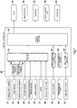
- Fig. 2 is a block diagram of the control apparatus 50 of the motorcycle 1 shown in Fig. 1 .
- the electronically controlled throttle device 41, the ignition plug 42, the fuel injector 43, the brake control unit 44, and an indicator 45 are connected to the output of the control apparatus 50. That is, the control apparatus 50 controls acceleration/deceleration of the motorcycle 1 and controls the mode of indication given by the indicator 45 (the mode includes an illuminated mode, an unilluminated mode, and a blinking mode, for example).
- the indicator 45 is located to be viewable by the rider R.
- the indicator 45 is provided in the meter device.
- a vehicle speed sensor 21 detects the travel speed of the motorcycle 1, such as in particular the rotational speed of the front wheel 3 (driven wheel).
- the rate sensor 22 detects the rate of change of the angular displacement of the vehicle body in the yaw, roll, or pitch direction.
- the rate sensor 22 is configured to determine the angular displacement of the vehicle body by calculating the integral of the detected rate of change of the angular displacement.
- the rider posture sensor 23 detects the amount of weight shift of the rider R sitting on the seat 14.
- a load sensor provided in the seat 14 or step member 18 or a steering torque sensor may be used as the rider posture sensor 23.
- the rate sensor 22 may serve as the rider posture sensor 23 to determine the change in posture of the rider from the rate of change of the angular displacement in the yaw, roll, or pitch direction.
- the blinker sensor 24 detects the turning on of the blinker.
- the accelerator operation amount sensor 25 detects the amount of operation of the acceleration operation member 11; namely, the accelerator operation amount sensor 25 detects the acceleration demanded by the rider R.
- the brake sensor 26 detects brake operation performed by the rider R or detects generation of brake pressure, thereby detecting the occurrence of a braking event.
- the GPS 27 is a known global positioning system that detects the current location of the motorcycle 1.
- the car navigation system 28 gives the rider guidance on the route from the current location of the motorcycle 1 to a destination.
- the laser sensor 29 emits a laser beam forward of the motorcycle 1 and receives the reflected wave to detect the distance between the motorcycle 1 and an object (target object) located ahead of the motorcycle 1.
- a millimeter-wave radar or a camera may be used to determine the distance to the object located ahead of the motorcycle.
- the forward imaging camera 30 captures images of the environment ahead of the motorcycle 1 to allow recognition of the condition of the road ahead of the motorcycle 1 (e.g., recognition of the travel lane).
- the skill input device 31 is intended to allow the rider R to input the level of his/her driving skill (e.g., beginner level, intermediate level, or advanced level).
- Software components of the control apparatus 50 include a bank angle calculation section 56, a rider posture calculation section 57, a prediction section 51, a target detection section 52, a travel lane recognition section 53, a skill setting section 54, and a vehicle control section 55.
- Hardware components of the control apparatus 50 include a processor, a volatile memory, a non-volatile memory, and an I/O interface.
- the prediction section 51, target detection section 52, lane recognition section 53, skill setting section 54, and vehicle control section 55 are implemented by processing operations performed by the processor using the volatile memory according to a program stored in the non-volatile memory.
- the control apparatus 50 may be constituted by a plurality of separate control units or may be configured as a single unit.
- the bank angle calculation section 56 calculates the integral of the angular displacement change rate detected by the rate sensor 22 for the roll direction of the motorcycle to determine the inclination angle (bank angle) of the vehicle body in the leftward/rightward direction.
- the rider posture calculation section 57 determines the posture of the rider from the amount of the rider R's weight shift detected by the rider posture sensor 23.
- the prediction section 51 determines whether the rider R intends to turn the vehicle and predicts whether turning of the vehicle will occur, before the vehicle actually makes a turn.
- the prediction section 51 makes the determination and prediction based on information related to a predetermined behavior exhibited by the vehicle body 2 before turning and a predetermined driving operation performed by the rider R.
- the prediction section 51 determines that the rider R intends to turn the vehicle.
- the threshold may be varied according to the vehicle speed. For example, the threshold may be increased with increasing vehicle speed so that the sensitivity of turning intention determination is increased during high-speed travel.
- the prediction section 51 determines whether the rider intends to turn the vehicle based on information including a change over time in the amount of accelerator operation performed by the rider.
- the amount of accelerator operation is detected by the accelerator operation amount sensor 25. For example, if, before turning of the vehicle, the amount of accelerator operation decreases (deceleration operation is performed) in a state where an increase in bank angle and/or a change in posture of the rider has been detected, the prediction section 51 determines that the rider R intends to turn the vehicle and predicts the occurrence of turning of the vehicle.
- the prediction section 51 may determine that the turning is about to be completed if the amount of accelerator operation increases (the vehicle is accelerated) when the bank angle has exceeded a predetermined angle (bank state).
- the prediction section 51 determines whether the rider intends to turn the vehicle based on information indicating braking event occurrence detected by the brake sensor 26. For example, if, before turning of the vehicle, a braking event occurs in a state where an increase in bank angle and/or a change in posture of the rider has been detected, the prediction section 51 determines that the rider R intends to turn the vehicle and predicts the occurrence of turning of the vehicle.
- the prediction section 51 determines that the rider R intends to turn the vehicle and predicts the occurrence of turning of the vehicle also when it is determined, based on map information, that the motorcycle 1's current location detected by the GPS 27 is coming closer to a curve.
- the prediction section 51 determines that the rider R intends to turn the vehicle.
- the target detection section 52 detects the distance between the motorcycle 1 and an object (target object) located ahead of the motorcycle 1 based on information obtained through the laser sensor 29 or any other sensor (e.g., a millimeter-wave radar or a camera).
- the lane recognition section 53 uses a known image recognition technology to recognize travel lane-dividing lines ahead of the motorcycle 1 from an image captured by the forward imaging camera 30, thereby recognizing the travel lane.
- the driving skill level input by the rider R through the skill input device 31 is set as the skill level of the rider R.
- the vehicle control section 55 provides driving assistance based on the result of the prediction made by the prediction section 51.
- Examples of the driving assistance include preceding vehicle follow-up control, collision avoidance control, and cruise control.
- the vehicle control section 55 controls the vehicle speed of the motorcycle 1 so that the inter-vehicle distance between a preceding vehicle and the motorcycle 1, which is detected by the target detection section 52, is maintained at a preset distance. Specifically, when the inter-vehicle distance is smaller than the preset distance, the vehicle control section 55 controls at least one of the electronically controlled throttle device 41, the ignition plug 42, and the fuel injector 43 to decrease the output of the engine E.
- the vehicle control section 55 controls the electronically controlled throttle device 41, the ignition plug 42, and the fuel injector 43 to increase the output of the engine E and/or controls the brake control unit 44 to cause at least one of the front and rear wheel brakes 15 and 16 to brake the corresponding wheel.
- a pulsed brake signal may be provided to cause the brakes 15 and 16 to perform intermittent braking.
- Fig. 3A shows a situation where both the motorcycle 1 and a preceding vehicle V are traveling straight and where the preceding vehicle V lies within a laser detection region L of the laser sensor 29.
- the preceding vehicle is traveling along a curve and the motorcycle 1 starts to enter the curve with its vehicle body 2 banked, the preceding vehicle V is moved relative to the motorcycle 1 in the turning direction and the laser detection region L is inclined. This deteriorates the accuracy of the detection of the preceding vehicle V by the laser sensor 29.
- the vehicle control section 55 corrects the information detected by the target detection section 52 or varies control parameters for the driving assistance.
- the vehicle control section 55 may, for example, make a correction by increasing the preset distance. If the inter-vehicle distance detected by the target detection section 52 abruptly increases at a rate higher than a predetermined rate (i.e., if the preceding vehicle V ceases to be detected) while it has been determined that there is an intention to turn the vehicle, the vehicle control section 55 may make a correction by fixing the inter-vehicle distance at a value detected immediately before the abrupt increase.
- the vehicle control section 55 may make a correction by fixing the inter-vehicle distance at a value detected immediately before the abrupt increase.
- the vehicle control section 55 may temporarily stop the preceding vehicle follow-up control until it is determined that the turning has been completed (e.g., until it is determined that the bank angle has returned to zero).
- the vehicle control section 55 controls the vehicle speed based on the vehicle turning predicted by the prediction section 51 to prevent the motorcycle from straying from the travel lane A recognized by the lane recognition section 53. For example, once the prediction section 51 determines that the rider R intends to turn the vehicle, the vehicle control section 55 takes into consideration the current vehicle state (e.g., the current vehicle speed or bank angle) and controls at least one of the electronically controlled throttle device 41, the ignition plug 42, and the fuel injector 43 to correct the output of the engine E to a certain engine output suitable for the current vehicle state.
- the current vehicle state e.g., the current vehicle speed or bank angle
- the vehicle control section 55 operates to cause deceleration and braking once the inter-vehicle distance between the preceding vehicle and the motorcycle 1, which is detected by the target detection section 52, becomes smaller than a predetermined threshold distance. Specifically, when the inter-vehicle distance is smaller than the threshold distance, the vehicle control section 55 controls at least one of the electronically controlled throttle device 41, the ignition plug 42, and the fuel injector 43 to decrease the output of the engine E and controls the brake control unit 44 to cause at least one of the front and rear wheel brakes 15 and 16 to brake the corresponding wheel.
- the vehicle control section 55 corrects the information detected by the target detection section 52 or varies the control parameters for the driving assistance. Upon determination that there is an intention to turn the vehicle, the vehicle control section 55 may, for example, make a correction by increasing the threshold distance. If the inter-vehicle distance detected by the target detection section 52 abruptly increases at a rate higher than a predetermined rate while it has been determined that there is an intention to turn the vehicle, the vehicle control section 55 may make a correction by fixing the inter-vehicle distance at a value detected immediately before the abrupt increase.
- the vehicle control section 55 controls the vehicle speed so that the vehicle speed detected by the vehicle speed sensor 21 is maintained at a preset speed. Specifically, when the vehicle speed is lower than the preset speed, the vehicle control section 55 controls at least one of the electronically controlled throttle device 41, the ignition plug 42, and the fuel injector 43 to increase the output of the engine E. When the vehicle speed is higher than the preset speed, the vehicle control section 55 controls the electronically controlled throttle device 41, the ignition plug 42, and the fuel injector 43 to decrease the output of the engine E and/or controls the brake control unit 44 to cause at least one of the front and rear wheel brakes 15 and 16 to brake the corresponding wheel.
- the vehicle control section 55 may vary the control parameters for the driving assistance. Upon determination that there is an intention to turn the vehicle, the vehicle control section 55 may, for example, make a correction by decreasing the preset speed. Upon determination that there is an intention to turn the vehicle, the vehicle control section 55 may temporarily stop the cruise control until it is determined that the turning has been completed (e.g., until it is determined that the bank angle has returned to zero).
- the vehicle control section 55 makes a correction also in detection of the vehicle speed.
- the vehicle control section 55 makes a correction by decreasing the vehicle speed detected by the vehicle speed sensor 21 with increase in the bank angle calculated by the bank angle calculation section 56.
- the vehicle control section 55 may make a correction by increasing a command value of drive power of the engine with increase in the bank angle calculated by the bank angle calculation section 56.
- the vehicle control section 55 when making a change in the driving assistance upon determination by the prediction section 51 that the rider R intends to turn the vehicle, the vehicle control section 55 changes the mode of indication given by the indicator 45. For example, the vehicle control section 55 changes the mode of indication given by the indicator 45 from an unilluminated mode to a blinking mode if, during execution of the driving assistance such as the preceding vehicle follow-up control, the information detected by the target detection section 52 is corrected or the control parameters for the driving assistance are varied upon determination that the rider intends to turn the vehicle.
- the vehicle control section 55 adjusts the driving assistance according to the driving skill set in the skill setting section 54 through the skill input device 31. For example, when “advanced level” is input as the driving skill in the skill setting section 54, the vehicle control section 55 may reduce the degree of change of the driving assistance, compared to when "beginner level” is input. For example, when “advanced level” is input, the vehicle control section 55 may reduce the rate of change of deceleration (change of the driving assistance), compared to when "beginner level” is input.
- the present invention is not limited to the embodiment described above, and modifications, additions, or omissions may be made to the above configuration.
- an electric motor for travel may be provided instead of or in addition to the engine E.
- a throttle device mechanically associated with the motion of the acceleration operation member 11 may be used instead of the electronically controlled throttle device 41.
- the prediction section 51 may determine whether the rider intends to turn the vehicle based on clutch operation.
- a sensor configured to detect the movement of the eyes of the rider or detect a positional shift of a helmet worn by the rider may be provided, and whether the rider intends to turn the vehicle may be determined based on the detection of the movement of the eyes of the rider in the leftward/rightward direction (e.g., the movement of the eyes toward a rear-view mirror) or based on the detection of the positional shift of the helmet in the leftward/rightward direction.
- the bank angle may be detected by a bank angle sensor rather than by the rate sensor.
Landscapes
- Engineering & Computer Science (AREA)
- Mechanical Engineering (AREA)
- Transportation (AREA)
- Automation & Control Theory (AREA)
- Chemical & Material Sciences (AREA)
- Combustion & Propulsion (AREA)
- Physics & Mathematics (AREA)
- Mathematical Physics (AREA)
- Control Of Driving Devices And Active Controlling Of Vehicle (AREA)
- Traffic Control Systems (AREA)
- Control Of Vehicle Engines Or Engines For Specific Uses (AREA)
Abstract
Description
- The present invention relates to a control apparatus of a straddle vehicle.
- Some straddle vehicles such as motorcycles have the function of assisting the rider in driving operations by controlling, for example, the vehicle speed (see
Patent Literature 1, for example). - Patent Literature 1: Japanese Laid-Open Patent Application Publication No.
2008-184950 - When a straddle vehicle such as a motorcycle makes a turn, the vehicle body of the straddle vehicle is inclined. It is desired for such a straddle vehicle to offer improved operation feeling during turning. In the case where the state of turning of the vehicle is detected and then the driving assistance is changed according to the state of turning of the vehicle, there is a time delay before the changed driving assistance is provided, and this time delay deteriorates the operation feeling experienced by the rider.
- It is therefore an object of the present invention to prevent delayed provision of driving assistance to a rider of a vehicle when the vehicle is traveling with its vehicle body inclined and improve the operation feeling experienced by the rider.
- A control apparatus of a straddle vehicle according to an aspect of the present invention includes: a prediction section that determines whether a rider of the straddle vehicle intends to turn the straddle vehicle and predicts whether turning of the straddle vehicle will occur, based on information related to at least one of a predetermined behavior exhibited by a vehicle body of the straddle vehicle before turning and a predetermined driving operation performed by the rider; and a vehicle control section that provides driving assistance during turning of the straddle vehicle based on a result of the prediction made by the prediction section.
- With the above configuration, since the driving assistance is provided in anticipation of the intention of the rider to turn the vehicle, early provision of the assistance can be achieved. This makes it possible to prevent delayed provision of driving assistance when the vehicle is traveling with its vehicle body inclined and improve the operation feeling experienced by the rider.
- Before turning of the vehicle, the prediction section may determine whether the rider intends to turn the straddle vehicle based on information including at least one of a change in bank angle of the vehicle body, a shift in posture of the rider, and a change in rotation angle of the vehicle body in a roll direction.
- With this configuration, since whether the rider intends to turn the vehicle is determined based on the behavior of the vehicle body or the rider, the determination can be made early before the actual occurrence of turning of the vehicle. For example, whether the rider intends to turn the vehicle may be determined by detecting a small change in yaw, roll, or pitch rate which is caused by weight shift of the rider.
- The prediction section may determine whether the rider intends to turn the straddle vehicle based on information including a change over time in the amount of the predetermined driving operation performed by the rider.
- With this configuration, since whether the rider intends to turn the vehicle is determined based on the change over time in the amount of the driving operation performed by the rider (e.g., the amount of accelerator operation, brake operation, or steering operation), the determination can be made early before the actual occurrence of turning of the vehicle. Whether the rider intends to turn the vehicle may be determined based on a change over time in the torque of the prime mover of the vehicle.
- The control apparatus may further include a skill setting section in which driving skill of the rider is set, and the vehicle control section may adjust the driving assistance according to the driving skill set in the skill setting section.
- With this configuration, for example, when the rider has a high driving skill, the convenience for the rider can be increased by decreasing the amount of the driving assistance.
- The control apparatus may further include a target detection section that detects a target object located ahead of the straddle vehicle, and the vehicle control section may provide the driving assistance based on the turning predicted by the prediction section and a result of detection made by the target detection section.
- With this configuration, driving assistance taking into account a target object (such as a preceding vehicle) located in a direction in which the straddle vehicle will turn (examples of such driving assistance include collision avoidance, collision mitigation, collision warning, and preceding vehicle follow-up) can be provided before the actual occurrence of turning of the vehicle.
- The vehicle control section may make a change in the driving assistance when a signal coming from the target object detection section changes from a state indicating detection of the target object to a state indicating non-detection of the target object and it is determined that the straddle vehicle is banked or it is predicted that turning of the straddle vehicle will occur.
- With this configuration, for example, in the case where the signal coming from the target object detection section changes into the state indicating non-detection because of banking of the vehicle body despite the presence of the target object ahead of the vehicle, the driving assistance can be appropriately adapted to the changed situation by making a change in the driving assistance (e.g., by temporarily reducing the amount of the driving assistance).
- When making a change in the driving assistance, the vehicle control section may change the mode of indication given by an indicator provided for the driving assistance.
- With this configuration, the rider can visually perceive the temporary reduction in the amount of the driving assistance and take advantage of this information in his/her driving operations.
- The control apparatus may further include a travel lane recognition section that recognizes a travel lane, and the vehicle control section may control the speed of the straddle vehicle based on the turning predicted by the prediction section to prevent the straddle vehicle from straying from the travel lane recognized by the travel lane recognition section.
- With this configuration, vehicle speed control (such as prime mover control or brake control) can be performed in consideration of turning of the vehicle before the actual occurrence of turning of the vehicle, and thus straying from the travel lane can be smoothly predicted and prevented.
- The vehicle control section may control the speed of the straddle vehicle based on a value detected by a vehicle speed sensor that detects the speed of the straddle vehicle from a wheel rotational speed, and upon increase in bank angle of the vehicle body, the vehicle control section may make a correction by decreasing the detected value of the speed of the straddle vehicle or by increasing a command value of drive power.
- With this configuration, when the vehicle speed value detected by the vehicle speed sensor is higher than an actual vehicle speed because of a decrease in the radius of tire contact area during banking of the vehicle body, a correction can be made by decreasing the detected vehicle speed value toward the actual vehicle speed or increasing the command value of the drive power of the prime mover so as to compensate for a decrease in the command value caused due to the detected vehicle speed value being higher than the actual vehicle speed. This enables appropriate vehicle speed control during a banked turn.
- The present invention makes it possible to prevent delayed provision of driving assistance to a rider of a vehicle when the vehicle is traveling with its vehicle body inclined and improve the operation feeling experienced by the rider.
-
-
Fig. 1 is a side view showing major components of a motorcycle according to an embodiment. -
Fig. 2 is a block diagram of a control apparatus of the motorcycle shown inFig. 1 . -
Figs. 3A and 3B are diagrams illustrating a radar detection region, whereFig. 3A shows the radar detection region in a situation where the motorcycle shown inFig. 1 is traveling in an upright position andFig. 3B shows the radar detection region in a situation where the motorcycle is making a banked turn. - Hereinafter, an embodiment will be described with reference to the drawings.
-
Fig. 1 is a side view showing major components of a motorcycle according to an embodiment. As shown inFig. 1 , themotorcycle 1 is an example of a straddle vehicle capable of traveling with itsvehicle body 2 banked (inclined) in a leftward/rightward direction. Themotorcycle 1 includes a front wheel 3 as a driven wheel and a rear wheel 4 as a drive wheel. Thevehicle body 2 includes ahead pipe portion 2a rotatably supporting a steering shaft (not illustrated) for steering of the front wheel 3 and aframe portion 2b extending rearwardly from thehead pipe portion 2a. An engine E is mounted on theframe portion 2b. A front end of aswing arm 9 is pivotally supported by a rear of theframe portion 2b, and the rear wheel 4 is rotatably supported by a rear end of theswing arm 9. The power output from the engine E is transmitted to the rear wheel 4 via a power transmission member (e.g., a chain or a belt). - A
front cowl 5 covering the front and sides of thehead pipe portion 2a is supported by thevehicle body 2 via abracket 6. Thebracket 6 is secured to thehead pipe portion 2a and connected to thefront cowl 5 and a meter display device (not illustrated). Thefront cowl 5 has a transmissive portion 5a that allows laser beams and light to pass therethrough. Alaser sensor 29 and aforward imaging camera 30 are attached to thebracket 6. Thelaser sensor 29 emits a laser beam forward of themotorcycle 1 through the transmissive portion 5a, and theforward imaging camera 30 captures images of the environment ahead of themotorcycle 1 through the transmissive portion 5a. - A bar-
shaped handle 10 extending in the leftward/rightward direction is connected to the steering shaft (not illustrated) supported by thehead pipe portion 2a. An acceleration operation member 11 (e.g., an accelerator grip) to which an acceleration command is input from the rider R is provided on a right-side portion of thehandle 10. A braking operation member 12 (e.g., a brake lever) to which a braking command is input from the rider R is provided forwardly of theacceleration operation member 11. Afuel tank 13 is provided rearwardly of thehandle 10, and aseat 14 on which the rider sits is provided rearwardly of thefuel tank 13. - A
front wheel brake 15 is attached to the front wheel 3. Arear wheel brake 16 is attached to the rear wheel 4. Thefront wheel brake 15 andrear wheel brake 16 are, for example, of the hydraulic pressure type. Abrake control unit 44 that controls braking forces to be generated by thefront wheel brake 15 andrear wheel brake 16 is installed in thevehicle body 2.Step members 18 on which the rider places his/her feet are provided below, and on both sides of, theseat 14. A braking operation member 19 (e.g., a brake pedal) to which a braking command is input from the rider R is provided on one of thestep members 18. Upon operation of thebraking operation member 12, mainly thefront wheel brake 15 works. Upon operation of thebraking operation member 19, mainly therear wheel brake 16 works. - An electronically controlled
throttle device 41 is provided on an air-intake passage communicating with an air-intake port of the engine E. The electronically controlledthrottle device 41 includes a throttle valve (not illustrated) disposed on the air-intake passage, and the position of the throttle valve is electronically controlled as a function of the amount of operation of theacceleration operation member 11. On the air-intake passage is provided a fuel injector 43 (seeFig. 2 ) that injects fuel delivered from thefuel tank 13 into the air-intake passage. The engine E includes an ignition plug 42 (seeFig. 2 ) that ignites air-fuel mixture present in the combustion chamber. Acontrol apparatus 50 is installed in thevehicle body 2. -
Fig. 2 is a block diagram of thecontrol apparatus 50 of themotorcycle 1 shown inFig. 1 . As shown inFig. 2 , the electronically controlledthrottle device 41, theignition plug 42, thefuel injector 43, thebrake control unit 44, and anindicator 45 are connected to the output of thecontrol apparatus 50. That is, thecontrol apparatus 50 controls acceleration/deceleration of themotorcycle 1 and controls the mode of indication given by the indicator 45 (the mode includes an illuminated mode, an unilluminated mode, and a blinking mode, for example). Theindicator 45 is located to be viewable by the rider R. For example, theindicator 45 is provided in the meter device. - To the input of the
control apparatus 50 there are connected avehicle speed sensor 21, arate sensor 22, arider posture sensor 23, ablinker sensor 24, an acceleratoroperation amount sensor 25, abrake sensor 26, aGPS 27, acar navigation system 28, thelaser sensor 29, theforward imaging camera 30, and askill input device 31. Thevehicle speed sensor 21 detects the travel speed of themotorcycle 1, such as in particular the rotational speed of the front wheel 3 (driven wheel). Therate sensor 22 detects the rate of change of the angular displacement of the vehicle body in the yaw, roll, or pitch direction. Therate sensor 22 is configured to determine the angular displacement of the vehicle body by calculating the integral of the detected rate of change of the angular displacement. - The
rider posture sensor 23 detects the amount of weight shift of the rider R sitting on theseat 14. For example, a load sensor provided in theseat 14 orstep member 18 or a steering torque sensor may be used as therider posture sensor 23. Therate sensor 22 may serve as therider posture sensor 23 to determine the change in posture of the rider from the rate of change of the angular displacement in the yaw, roll, or pitch direction. - When the rider R turns on the blinker (causes the blinker to blink), the
blinker sensor 24 detects the turning on of the blinker. The acceleratoroperation amount sensor 25 detects the amount of operation of theacceleration operation member 11; namely, the acceleratoroperation amount sensor 25 detects the acceleration demanded by the rider R. Thebrake sensor 26 detects brake operation performed by the rider R or detects generation of brake pressure, thereby detecting the occurrence of a braking event. TheGPS 27 is a known global positioning system that detects the current location of themotorcycle 1. Thecar navigation system 28 gives the rider guidance on the route from the current location of themotorcycle 1 to a destination. - The
laser sensor 29 emits a laser beam forward of themotorcycle 1 and receives the reflected wave to detect the distance between themotorcycle 1 and an object (target object) located ahead of themotorcycle 1. Instead of thelaser sensor 29, a millimeter-wave radar or a camera may be used to determine the distance to the object located ahead of the motorcycle. Theforward imaging camera 30 captures images of the environment ahead of themotorcycle 1 to allow recognition of the condition of the road ahead of the motorcycle 1 (e.g., recognition of the travel lane). Theskill input device 31 is intended to allow the rider R to input the level of his/her driving skill (e.g., beginner level, intermediate level, or advanced level). - Software components of the
control apparatus 50 include a bankangle calculation section 56, a riderposture calculation section 57, aprediction section 51, atarget detection section 52, a travellane recognition section 53, askill setting section 54, and avehicle control section 55. Hardware components of thecontrol apparatus 50 include a processor, a volatile memory, a non-volatile memory, and an I/O interface. Theprediction section 51,target detection section 52,lane recognition section 53,skill setting section 54, andvehicle control section 55 are implemented by processing operations performed by the processor using the volatile memory according to a program stored in the non-volatile memory. Thecontrol apparatus 50 may be constituted by a plurality of separate control units or may be configured as a single unit. - The bank
angle calculation section 56 calculates the integral of the angular displacement change rate detected by therate sensor 22 for the roll direction of the motorcycle to determine the inclination angle (bank angle) of the vehicle body in the leftward/rightward direction. The riderposture calculation section 57 determines the posture of the rider from the amount of the rider R's weight shift detected by therider posture sensor 23. - If the
vehicle speed sensor 21 detects that the vehicle is traveling, theprediction section 51 determines whether the rider R intends to turn the vehicle and predicts whether turning of the vehicle will occur, before the vehicle actually makes a turn. Theprediction section 51 makes the determination and prediction based on information related to a predetermined behavior exhibited by thevehicle body 2 before turning and a predetermined driving operation performed by the rider R. If the bank angle determined by the bankangle calculation section 56 or the rate of change of the bank angle exceeds a predetermined threshold before turning of the vehicle and/or if therider posture sensor 23 detects a change in posture of the rider in the leftward/rightward direction, in the forward/rearward direction, and/or in the upward/downward direction before turning of the vehicle, theprediction section 51 determines that the rider R intends to turn the vehicle. The threshold may be varied according to the vehicle speed. For example, the threshold may be increased with increasing vehicle speed so that the sensitivity of turning intention determination is increased during high-speed travel. - The
prediction section 51 determines whether the rider intends to turn the vehicle based on information including a change over time in the amount of accelerator operation performed by the rider. The amount of accelerator operation is detected by the acceleratoroperation amount sensor 25. For example, if, before turning of the vehicle, the amount of accelerator operation decreases (deceleration operation is performed) in a state where an increase in bank angle and/or a change in posture of the rider has been detected, theprediction section 51 determines that the rider R intends to turn the vehicle and predicts the occurrence of turning of the vehicle. Theprediction section 51 may determine that the turning is about to be completed if the amount of accelerator operation increases (the vehicle is accelerated) when the bank angle has exceeded a predetermined angle (bank state). - The
prediction section 51 determines whether the rider intends to turn the vehicle based on information indicating braking event occurrence detected by thebrake sensor 26. For example, if, before turning of the vehicle, a braking event occurs in a state where an increase in bank angle and/or a change in posture of the rider has been detected, theprediction section 51 determines that the rider R intends to turn the vehicle and predicts the occurrence of turning of the vehicle. - The
prediction section 51 determines that the rider R intends to turn the vehicle and predicts the occurrence of turning of the vehicle also when it is determined, based on map information, that themotorcycle 1's current location detected by theGPS 27 is coming closer to a curve. When thecar navigation system 28 gives guidance instructing the rider R to make a turn (e.g., guidance instructing the rider to turn to the right or left), theprediction section 51 determines that the rider R intends to turn the vehicle. - The
target detection section 52 detects the distance between themotorcycle 1 and an object (target object) located ahead of themotorcycle 1 based on information obtained through thelaser sensor 29 or any other sensor (e.g., a millimeter-wave radar or a camera). Thelane recognition section 53 uses a known image recognition technology to recognize travel lane-dividing lines ahead of themotorcycle 1 from an image captured by theforward imaging camera 30, thereby recognizing the travel lane. In theskill setting section 54, the driving skill level input by the rider R through theskill input device 31 is set as the skill level of the rider R. - During turning of the vehicle, the
vehicle control section 55 provides driving assistance based on the result of the prediction made by theprediction section 51. Examples of the driving assistance include preceding vehicle follow-up control, collision avoidance control, and cruise control. - In the preceding vehicle follow-up control, the
vehicle control section 55 controls the vehicle speed of themotorcycle 1 so that the inter-vehicle distance between a preceding vehicle and themotorcycle 1, which is detected by thetarget detection section 52, is maintained at a preset distance. Specifically, when the inter-vehicle distance is smaller than the preset distance, thevehicle control section 55 controls at least one of the electronically controlledthrottle device 41, theignition plug 42, and thefuel injector 43 to decrease the output of the engine E. When the inter-vehicle distance is greater than the preset distance, thevehicle control section 55 controls the electronically controlledthrottle device 41, theignition plug 42, and thefuel injector 43 to increase the output of the engine E and/or controls thebrake control unit 44 to cause at least one of the front andrear wheel brakes vehicle control section 55 controls thebrake control unit 44, a pulsed brake signal may be provided to cause thebrakes -
Fig. 3A shows a situation where both themotorcycle 1 and a preceding vehicle V are traveling straight and where the preceding vehicle V lies within a laser detection region L of thelaser sensor 29. When, as shown inFig. 3B , the preceding vehicle is traveling along a curve and themotorcycle 1 starts to enter the curve with itsvehicle body 2 banked, the preceding vehicle V is moved relative to themotorcycle 1 in the turning direction and the laser detection region L is inclined. This deteriorates the accuracy of the detection of the preceding vehicle V by thelaser sensor 29. Thus, once theprediction section 51 determines, during preceding vehicle follow-up control, that the rider R intends to turn the vehicle, thevehicle control section 55 corrects the information detected by thetarget detection section 52 or varies control parameters for the driving assistance. - Upon determination that there is an intention to turn the vehicle, the
vehicle control section 55 may, for example, make a correction by increasing the preset distance. If the inter-vehicle distance detected by thetarget detection section 52 abruptly increases at a rate higher than a predetermined rate (i.e., if the preceding vehicle V ceases to be detected) while it has been determined that there is an intention to turn the vehicle, thevehicle control section 55 may make a correction by fixing the inter-vehicle distance at a value detected immediately before the abrupt increase. If the inter-vehicle distance detected by thetarget detection section 52 abruptly increases at a rate higher than a predetermined rate (i.e., if the preceding vehicle V ceases to be detected) while it has been determined that the bank angle calculated by the bankangle calculation section 56 is larger than a predetermined threshold, thevehicle control section 55 may make a correction by fixing the inter-vehicle distance at a value detected immediately before the abrupt increase. Upon determination that there is an intention to turn the vehicle, thevehicle control section 55 may temporarily stop the preceding vehicle follow-up control until it is determined that the turning has been completed (e.g., until it is determined that the bank angle has returned to zero). - Additionally, the
vehicle control section 55 controls the vehicle speed based on the vehicle turning predicted by theprediction section 51 to prevent the motorcycle from straying from the travel lane A recognized by thelane recognition section 53. For example, once theprediction section 51 determines that the rider R intends to turn the vehicle, thevehicle control section 55 takes into consideration the current vehicle state (e.g., the current vehicle speed or bank angle) and controls at least one of the electronically controlledthrottle device 41, theignition plug 42, and thefuel injector 43 to correct the output of the engine E to a certain engine output suitable for the current vehicle state. - In the collision avoidance control, the
vehicle control section 55 operates to cause deceleration and braking once the inter-vehicle distance between the preceding vehicle and themotorcycle 1, which is detected by thetarget detection section 52, becomes smaller than a predetermined threshold distance. Specifically, when the inter-vehicle distance is smaller than the threshold distance, thevehicle control section 55 controls at least one of the electronically controlledthrottle device 41, theignition plug 42, and thefuel injector 43 to decrease the output of the engine E and controls thebrake control unit 44 to cause at least one of the front andrear wheel brakes - When the
prediction section 51 determines, during the collision avoidance control, that the rider R intends to turn the vehicle, thevehicle control section 55 corrects the information detected by thetarget detection section 52 or varies the control parameters for the driving assistance. Upon determination that there is an intention to turn the vehicle, thevehicle control section 55 may, for example, make a correction by increasing the threshold distance. If the inter-vehicle distance detected by thetarget detection section 52 abruptly increases at a rate higher than a predetermined rate while it has been determined that there is an intention to turn the vehicle, thevehicle control section 55 may make a correction by fixing the inter-vehicle distance at a value detected immediately before the abrupt increase. - In the cruise control, the
vehicle control section 55 controls the vehicle speed so that the vehicle speed detected by thevehicle speed sensor 21 is maintained at a preset speed. Specifically, when the vehicle speed is lower than the preset speed, thevehicle control section 55 controls at least one of the electronically controlledthrottle device 41, theignition plug 42, and thefuel injector 43 to increase the output of the engine E. When the vehicle speed is higher than the preset speed, thevehicle control section 55 controls the electronically controlledthrottle device 41, theignition plug 42, and thefuel injector 43 to decrease the output of the engine E and/or controls thebrake control unit 44 to cause at least one of the front andrear wheel brakes - When the
prediction section 51 determines, during the cruise control, that the rider R intends to turn the vehicle, thevehicle control section 55 may vary the control parameters for the driving assistance. Upon determination that there is an intention to turn the vehicle, thevehicle control section 55 may, for example, make a correction by decreasing the preset speed. Upon determination that there is an intention to turn the vehicle, thevehicle control section 55 may temporarily stop the cruise control until it is determined that the turning has been completed (e.g., until it is determined that the bank angle has returned to zero). - The
vehicle control section 55 makes a correction also in detection of the vehicle speed. As the bank angle calculated by the bankangle calculation section 56 increases, the ground contact area of the wheel (front wheel 3) whose rotational speed is detected by thevehicle speed sensor 21 is shifted in the leftward/rightward direction in which the vehicle body is banked, and the contact radius of the wheel (the radius of the ground contact area of the wheel) decreases. For this reason, the vehicle speed detected by thevehicle speed sensor 21 becomes higher than the actual vehicle speed as the bank angle increases. Thus, thevehicle control section 55 makes a correction by decreasing the vehicle speed detected by thevehicle speed sensor 21 with increase in the bank angle calculated by the bankangle calculation section 56. Alternatively, thevehicle control section 55 may make a correction by increasing a command value of drive power of the engine with increase in the bank angle calculated by the bankangle calculation section 56. - Additionally, when making a change in the driving assistance upon determination by the
prediction section 51 that the rider R intends to turn the vehicle, thevehicle control section 55 changes the mode of indication given by theindicator 45. For example, thevehicle control section 55 changes the mode of indication given by theindicator 45 from an unilluminated mode to a blinking mode if, during execution of the driving assistance such as the preceding vehicle follow-up control, the information detected by thetarget detection section 52 is corrected or the control parameters for the driving assistance are varied upon determination that the rider intends to turn the vehicle. - Additionally, the
vehicle control section 55 adjusts the driving assistance according to the driving skill set in theskill setting section 54 through theskill input device 31. For example, when "advanced level" is input as the driving skill in theskill setting section 54, thevehicle control section 55 may reduce the degree of change of the driving assistance, compared to when "beginner level" is input. For example, when "advanced level" is input, thevehicle control section 55 may reduce the rate of change of deceleration (change of the driving assistance), compared to when "beginner level" is input. - The present invention is not limited to the embodiment described above, and modifications, additions, or omissions may be made to the above configuration. For example, an electric motor for travel may be provided instead of or in addition to the engine E. A throttle device mechanically associated with the motion of the
acceleration operation member 11 may be used instead of the electronically controlledthrottle device 41. Theprediction section 51 may determine whether the rider intends to turn the vehicle based on clutch operation. A sensor configured to detect the movement of the eyes of the rider or detect a positional shift of a helmet worn by the rider may be provided, and whether the rider intends to turn the vehicle may be determined based on the detection of the movement of the eyes of the rider in the leftward/rightward direction (e.g., the movement of the eyes toward a rear-view mirror) or based on the detection of the positional shift of the helmet in the leftward/rightward direction. The bank angle may be detected by a bank angle sensor rather than by the rate sensor. -
- 1
- Motorcycle (straddle vehicle)
- 2
- Vehicle body
- 21
- Vehicle speed sensor
- 45
- Indicator
- 50
- Control apparatus
- 51
- Prediction section
- 52
- Target detection section
- 53
- Lane recognition section
- 54
- Skill setting section
- 55
- Vehicle control section
Claims (9)
- A control apparatus of a straddle vehicle, comprising:a prediction section that determines whether a rider of the straddle vehicle intends to turn the straddle vehicle and predicts whether turning of the straddle vehicle will occur, based on information related to at least one of a predetermined behavior exhibited by a vehicle body of the straddle vehicle before turning and a predetermined driving operation performed by the rider; anda vehicle control section that provides driving assistance during turning of the straddle vehicle based on a result of the prediction made by the prediction section.
- The control apparatus according to claim 1, wherein before turning of the straddle vehicle, the prediction section determines whether the rider intends to turn the straddle vehicle based on information including at least one of a change in bank angle of the vehicle body, a shift in posture of the rider, and a change in rotation angle of the vehicle body in a roll direction.
- The control apparatus according to claim 1 or 2, wherein the prediction section determines whether the rider intends to turn the straddle vehicle based on information including a change over time in the amount of the predetermined driving operation performed by the rider.
- The control apparatus according to any one of claims 1 to 3, further comprising a skill setting section in which driving skill of the rider is set, wherein
the vehicle control section adjusts the driving assistance according to the driving skill set in the skill setting section. - The control apparatus according to any one of claims 1 to 4, further comprising a target detection section that detects a target object located ahead of the straddle vehicle, wherein
the vehicle control section provides the driving assistance based on the turning predicted by the prediction section and a result of the detection made by the target detection section. - The control apparatus according to claim 5, wherein the vehicle control section makes a change in the driving assistance when a signal coming from the target object detection section changes from a state indicating detection of the target object to a state indicating non-detection of the target object and it is determined that the straddle vehicle is banked or it is predicted that turning of the straddle vehicle will occur.
- The control apparatus according to claim 6, wherein when making a change in the driving assistance, the vehicle control section changes the mode of indication given by an indicator provided for the driving assistance.
- The control apparatus according to any one of claims 1 to 7, further comprising a travel lane recognition section that recognizes a travel lane, wherein
the vehicle control section controls the speed of the straddle vehicle based on the turning predicted by the prediction section to prevent the straddle vehicle from straying from the travel lane recognized by the travel lane recognition section. - The control apparatus according to any one of claims 1 to 8, wherein
the vehicle control section controls the speed of the straddle vehicle based on a value detected by a vehicle speed sensor that detects the speed of the straddle vehicle from a wheel rotational speed, and
upon increase in bank angle of the vehicle body, the vehicle control section makes a correction by decreasing the detected value of the speed of the straddle vehicle or by increasing a command value of drive power.
Applications Claiming Priority (2)
| Application Number | Priority Date | Filing Date | Title |
|---|---|---|---|
| JP2017102688A JP6991434B2 (en) | 2017-05-24 | 2017-05-24 | Saddle-type vehicle control device |
| PCT/JP2018/008784 WO2018216308A1 (en) | 2017-05-24 | 2018-03-07 | Saddle-type vehicle control apparatus |
Publications (3)
| Publication Number | Publication Date |
|---|---|
| EP3632783A1 true EP3632783A1 (en) | 2020-04-08 |
| EP3632783A4 EP3632783A4 (en) | 2021-03-03 |
| EP3632783B1 EP3632783B1 (en) | 2023-07-26 |
Family
ID=64396498
Family Applications (1)
| Application Number | Title | Priority Date | Filing Date |
|---|---|---|---|
| EP18805425.8A Active EP3632783B1 (en) | 2017-05-24 | 2018-03-07 | Control apparatus of straddle vehicle |
Country Status (4)
| Country | Link |
|---|---|
| US (1) | US11084376B2 (en) |
| EP (1) | EP3632783B1 (en) |
| JP (1) | JP6991434B2 (en) |
| WO (1) | WO2018216308A1 (en) |
Cited By (3)
| Publication number | Priority date | Publication date | Assignee | Title |
|---|---|---|---|---|
| WO2022269505A1 (en) * | 2021-06-25 | 2022-12-29 | ロベルト·ボッシュ·ゲゼルシャフト·ミト•ベシュレンクテル·ハフツング | Control device and control method |
| WO2024069270A1 (en) * | 2022-09-30 | 2024-04-04 | ロベルト•ボッシュ•ゲゼルシャフト•ミト•ベシュレンクテル•ハフツング | Control device and control method |
| WO2025046351A1 (en) * | 2023-08-30 | 2025-03-06 | ロベルト•ボッシュ•ゲゼルシャフト•ミト•ベシュレンクテル•ハフツング | Control device and control method for rider assist system |
Families Citing this family (29)
| Publication number | Priority date | Publication date | Assignee | Title |
|---|---|---|---|---|
| JP2020050221A (en) * | 2018-09-28 | 2020-04-02 | ロベルト・ボッシュ・ゲゼルシャフト・ミト・ベシュレンクテル・ハフツングRobert Bosch Gmbh | Control device and control method |
| DE102018219027A1 (en) * | 2018-11-08 | 2020-05-14 | Robert Bosch Gmbh | Method and device for the driver-independent temporary deactivation of a constant speed function for a single-track motor vehicle |
| DE102018221720A1 (en) * | 2018-12-13 | 2020-06-18 | Robert Bosch Gmbh | Method and device for performing autonomous braking in a single-track motor vehicle |
| JP7106752B2 (en) * | 2019-03-29 | 2022-07-26 | 本田技研工業株式会社 | Driving support device for saddle type vehicle |
| JPWO2020202283A1 (en) * | 2019-03-29 | 2021-11-25 | 本田技研工業株式会社 | Driving support device for saddle-riding vehicles |
| US20220161788A1 (en) * | 2019-03-29 | 2022-05-26 | Honda Motor Co., Ltd. | Driving support device of saddle-riding type vehicle |
| JP7143510B2 (en) | 2019-03-29 | 2022-09-28 | 本田技研工業株式会社 | Driving support device for saddle type vehicle |
| JP7170125B2 (en) * | 2019-03-29 | 2022-11-11 | 本田技研工業株式会社 | Driving support device for saddle type vehicle |
| WO2020202261A1 (en) * | 2019-03-29 | 2020-10-08 | 本田技研工業株式会社 | Driving assistance device for saddle-type vehicles |
| JP7226052B2 (en) * | 2019-04-16 | 2023-02-21 | スズキ株式会社 | Accident Judgment System, Accident Judgment Method, Program |
| EP3730391A1 (en) * | 2019-04-25 | 2020-10-28 | Robert Bosch GmbH | Method for warning a driver of a motorcycle as well as ride assistant controller and motorcycle implementing such method |
| JP2020203654A (en) * | 2019-06-19 | 2020-12-24 | ロベルト・ボッシュ・ゲゼルシャフト・ミト・ベシュレンクテル・ハフツングRobert Bosch Gmbh | Control apparatus and control method |
| EP4012682B1 (en) * | 2019-09-26 | 2024-01-17 | Yamaha Hatsudoki Kabushiki Kaisha | Leaning vehicle comprising fcw control device |
| DE112020004697T5 (en) | 2019-09-30 | 2022-06-23 | Honda Motor Co., Ltd. | STEERING ASSISTANT DEVICE FOR A SIDE RIDER VEHICLE |
| WO2021079497A1 (en) * | 2019-10-25 | 2021-04-29 | ヤマハ発動機株式会社 | Real-time information presentation control apparatus for leaning vehicle |
| JP2021088321A (en) * | 2019-12-06 | 2021-06-10 | ロベルト・ボッシュ・ゲゼルシャフト・ミト・ベシュレンクテル・ハフツングRobert Bosch Gmbh | Rider support system, and control method of rider support system |
| JP2021105813A (en) * | 2019-12-26 | 2021-07-26 | ロベルト・ボッシュ・ゲゼルシャフト・ミト・ベシュレンクテル・ハフツングRobert Bosch Gmbh | Control device and control method |
| JP2022099972A (en) * | 2020-12-23 | 2022-07-05 | ロベルト・ボッシュ・ゲゼルシャフト・ミト・ベシュレンクテル・ハフツング | Control device and control method of controlling operation of motor cycle |
| JP7637513B2 (en) | 2021-01-12 | 2025-02-28 | 日立Astemo株式会社 | Vehicle control device |
| DE112021006645T5 (en) * | 2021-03-04 | 2023-10-19 | Honda Motor Co., Ltd. | BRAKE SYSTEM FOR A SADDLE SEAT VEHICLE |
| JP7134304B1 (en) | 2021-06-21 | 2022-09-09 | 三菱電機株式会社 | Driving support control device |
| DE102021212360A1 (en) * | 2021-11-03 | 2023-05-04 | Robert Bosch Gesellschaft mit beschränkter Haftung | Method for detecting a change of direction in a single-track vehicle |
| WO2023191105A1 (en) * | 2022-03-31 | 2023-10-05 | 本田技研工業株式会社 | Saddle-ridden vehicle |
| US20260159082A1 (en) * | 2022-06-30 | 2026-06-11 | Robert Bosch Gmbh | Controller and control method for rider-assistance system |
| JP7543359B2 (en) * | 2022-09-30 | 2024-09-02 | 本田技研工業株式会社 | Driving assistance system for saddle-type vehicles |
| CN116331182A (en) * | 2023-04-11 | 2023-06-27 | 天津爱玛运动用品有限公司 | An intelligent riding control system and method for a two-wheeled vehicle |
| TWI866623B (en) * | 2023-11-17 | 2024-12-11 | 鴻海精密工業股份有限公司 | Driving assistance method, on-board computer and bicycle |
| WO2025171050A1 (en) * | 2024-02-05 | 2025-08-14 | Virginia Tech Intellectual Properties, Inc. | Motorcycle collision alert and management system |
| WO2025196928A1 (en) * | 2024-03-19 | 2025-09-25 | Astemo株式会社 | Driving assistance system for saddle-type vehicle |
Family Cites Families (40)
| Publication number | Priority date | Publication date | Assignee | Title |
|---|---|---|---|---|
| JP2002326525A (en) | 2001-05-07 | 2002-11-12 | Nissan Motor Co Ltd | Vehicle travel control device |
| JP4138441B2 (en) | 2002-10-18 | 2008-08-27 | 本田技研工業株式会社 | Vehicle control device |
| ES2361319T3 (en) | 2003-10-20 | 2011-06-16 | Yamaha Hatsudoki Kabushiki Kaisha | PROCEDURE AND SYSTEM FOR STORAGE OF MOTORCYCLE DRIVING INFORMATION. |
| WO2005092659A1 (en) | 2004-03-23 | 2005-10-06 | Continental Teves Ag & Co.Ohg | Single-track vehicle comprising a brake control unit |
| JP4617915B2 (en) | 2004-08-30 | 2011-01-26 | トヨタ自動車株式会社 | Vehicle traveling path estimation device and vehicle deceleration control device |
| US7674022B2 (en) * | 2006-11-09 | 2010-03-09 | Kawasaki Jukogyo Kabushiki Kaisha | Motorcycle headlight device |
| JP4745258B2 (en) | 2007-01-29 | 2011-08-10 | 川崎重工業株式会社 | Electronically controlled throttle device and motorcycle |
| JP5046384B2 (en) * | 2007-09-19 | 2012-10-10 | 本田技研工業株式会社 | Saddle-type fuel cell tricycle |
| DE102007061114A1 (en) * | 2007-12-19 | 2009-06-25 | Robert Bosch Gmbh | Motorcycle with a brake and steering assistant |
| EP2138368B1 (en) * | 2008-06-26 | 2013-03-20 | Kawasaki Jukogyo Kabushiki Kaisha | Slip suppression control system for vehicle |
| JP5134527B2 (en) * | 2008-12-25 | 2013-01-30 | 川崎重工業株式会社 | Motorcycle bank angle detector and headlamp device |
| JP5369999B2 (en) | 2009-08-27 | 2013-12-18 | 株式会社エクォス・リサーチ | vehicle |
| CN102686476B (en) * | 2009-12-25 | 2014-10-08 | 雅马哈发动机株式会社 | Driver characteristic judging device and saddled vehicle including said driver characteristic judging device |
| ITTO20100454T1 (en) * | 2010-05-28 | 2011-11-29 | Univ Padova | A method of assisting a rider to negotiate a roadway and related curve support system, motorcycle and computer program product |
| JP5752379B2 (en) * | 2010-09-22 | 2015-07-22 | 川崎重工業株式会社 | Vehicle bank angle detector |
| WO2012067234A1 (en) * | 2010-11-19 | 2012-05-24 | ヤマハ発動機株式会社 | Automatic two-wheeled vehicle and control device therefor |
| JP2012214088A (en) * | 2011-03-31 | 2012-11-08 | Honda Motor Co Ltd | Electric tricycle |
| JP2012224316A (en) * | 2011-04-22 | 2012-11-15 | Mitsubishi Motors Corp | Drive control device |
| US8725312B2 (en) * | 2011-08-12 | 2014-05-13 | Kawasaki Jukogyo Kabushiki Kaisha | System for obtaining information in vehicle |
| JP2013086580A (en) | 2011-10-14 | 2013-05-13 | Clarion Co Ltd | Vehicle traveling control device and method |
| JP5615870B2 (en) * | 2012-03-19 | 2014-10-29 | ヤマハ発動機株式会社 | Sub headlight unit and sub headlight system for a vehicle turning in a lean position, and a vehicle turning in a lean position |
| JP5840108B2 (en) * | 2012-11-01 | 2016-01-06 | 本田技研工業株式会社 | Moving body |
| JP6094337B2 (en) | 2013-04-04 | 2017-03-15 | 日産自動車株式会社 | Operation control device |
| JP6252007B2 (en) | 2013-07-17 | 2017-12-27 | 日産自動車株式会社 | Convoy travel control device, convoy travel control method, travel control device |
| JP6180855B2 (en) * | 2013-09-03 | 2017-08-16 | 株式会社ショーワ | Saddle type vehicle seat and saddle type vehicle |
| JP5844331B2 (en) * | 2013-10-21 | 2016-01-13 | ヤマハ発動機株式会社 | Longitudinal force control device and saddle riding type vehicle equipped with the same |
| DE102014205070A1 (en) * | 2014-03-19 | 2015-09-24 | Bayerische Motoren Werke Aktiengesellschaft | Route planning with improved curve data |
| JP6410509B2 (en) | 2014-08-04 | 2018-10-24 | 株式会社エフ・シー・シー | Saddle riding |
| JP5972332B2 (en) * | 2014-09-26 | 2016-08-17 | 本田技研工業株式会社 | Approach notification device for saddle riding type vehicles |
| JP2016068769A (en) | 2014-09-30 | 2016-05-09 | 本田技研工業株式会社 | Saddle-riding type vehicle |
| JP2016119247A (en) * | 2014-12-22 | 2016-06-30 | 新電元工業株式会社 | Auxiliary lighting device for vehicle, and auxiliary lighting system for vehicle |
| JP6179820B2 (en) | 2015-02-18 | 2017-08-16 | トヨタ自動車株式会社 | Vehicle driving support control device |
| JP2017001484A (en) * | 2015-06-09 | 2017-01-05 | 新電元工業株式会社 | Lighting device with blinker |
| JP6214601B2 (en) * | 2015-07-27 | 2017-10-18 | 本田技研工業株式会社 | Automatic braking system for saddle-ride type vehicles |
| EP3335954A4 (en) | 2015-08-17 | 2018-09-12 | Yamaha Hatsudoki Kabushiki Kaisha | Leaning vehicle |
| JP6651320B2 (en) * | 2015-09-30 | 2020-02-19 | 川崎重工業株式会社 | Vehicle bank angle detector |
| JP6636294B2 (en) | 2015-09-30 | 2020-01-29 | 川崎重工業株式会社 | Vehicle ground speed detector |
| JP2017074820A (en) * | 2015-10-13 | 2017-04-20 | スズキ株式会社 | Notification system for vehicle |
| JP6314961B2 (en) * | 2015-11-12 | 2018-04-25 | マツダ株式会社 | Lane maintenance control device |
| US11358574B2 (en) * | 2016-03-31 | 2022-06-14 | Honda Motor Co., Ltd. | Brake control device for motorcycle |
-
2017
- 2017-05-24 JP JP2017102688A patent/JP6991434B2/en active Active
-
2018
- 2018-03-07 WO PCT/JP2018/008784 patent/WO2018216308A1/en not_active Ceased
- 2018-03-07 EP EP18805425.8A patent/EP3632783B1/en active Active
- 2018-03-07 US US16/615,197 patent/US11084376B2/en active Active
Cited By (3)
| Publication number | Priority date | Publication date | Assignee | Title |
|---|---|---|---|---|
| WO2022269505A1 (en) * | 2021-06-25 | 2022-12-29 | ロベルト·ボッシュ·ゲゼルシャフト·ミト•ベシュレンクテル·ハフツング | Control device and control method |
| WO2024069270A1 (en) * | 2022-09-30 | 2024-04-04 | ロベルト•ボッシュ•ゲゼルシャフト•ミト•ベシュレンクテル•ハフツング | Control device and control method |
| WO2025046351A1 (en) * | 2023-08-30 | 2025-03-06 | ロベルト•ボッシュ•ゲゼルシャフト•ミト•ベシュレンクテル•ハフツング | Control device and control method for rider assist system |
Also Published As
| Publication number | Publication date |
|---|---|
| EP3632783B1 (en) | 2023-07-26 |
| JP2018197071A (en) | 2018-12-13 |
| EP3632783A4 (en) | 2021-03-03 |
| WO2018216308A1 (en) | 2018-11-29 |
| US11084376B2 (en) | 2021-08-10 |
| US20200171946A1 (en) | 2020-06-04 |
| JP6991434B2 (en) | 2022-01-12 |
Similar Documents
| Publication | Publication Date | Title |
|---|---|---|
| US11084376B2 (en) | Control apparatus of straddle vehicle | |
| US11970163B2 (en) | Lane change assist device | |
| US10600324B2 (en) | Lane change assist device | |
| JP6176263B2 (en) | Automatic driving device | |
| US11613307B2 (en) | Vehicle contact avoidance assist system | |
| US20220161788A1 (en) | Driving support device of saddle-riding type vehicle | |
| EP1484732B1 (en) | Driving assist system for vehicle | |
| US20220135165A1 (en) | Drive assistance device for saddle riding-type vehicle | |
| US20030014162A1 (en) | Lane-keep control system for vehicle | |
| US20080185207A1 (en) | Vehicle travel control system | |
| CN113631471B (en) | Driving support device for saddle-ride type vehicle | |
| US11990043B2 (en) | Processor and processing method for rider-assistance system of straddle-type vehicle, rider-assistance system of straddle-type vehicle, and straddle-type vehicle | |
| CN113631470A (en) | Driving support device for saddle-riding vehicle | |
| WO2017159792A1 (en) | Travel assistance device | |
| JP5772651B2 (en) | Driving assistance device | |
| JP2020040648A (en) | Methods of driving automobiles, especially motorcycles, computer programs | |
| US12110036B2 (en) | Controller for rider-assistance system, rider-assistance system, and control method for rider-assistance system | |
| JPWO2020065434A1 (en) | Control device and control method | |
| KR20240120654A (en) | Parking assist device and parking assist method | |
| CN112739595A (en) | Control device and control method | |
| US12233868B2 (en) | Driving-assistance control apparatus | |
| JP7261866B2 (en) | CONTROL DEVICE AND CONTROL METHOD FOR CONTROLLING MOTORCYCLE OPERATION | |
| JP2004331026A (en) | VEHICLE DRIVE OPERATION ASSISTANCE DEVICE AND VEHICLE HAVING THE DEVICE | |
| US12583548B2 (en) | Controller and control method for rider assistance system | |
| EP4737243A1 (en) | Control device and control method for rider assistance system |
Legal Events
| Date | Code | Title | Description |
|---|---|---|---|
| STAA | Information on the status of an ep patent application or granted ep patent |
Free format text: STATUS: THE INTERNATIONAL PUBLICATION HAS BEEN MADE |
|
| PUAI | Public reference made under article 153(3) epc to a published international application that has entered the european phase |
Free format text: ORIGINAL CODE: 0009012 |
|
| STAA | Information on the status of an ep patent application or granted ep patent |
Free format text: STATUS: REQUEST FOR EXAMINATION WAS MADE |
|
| 17P | Request for examination filed |
Effective date: 20191217 |
|
| AK | Designated contracting states |
Kind code of ref document: A1 Designated state(s): AL AT BE BG CH CY CZ DE DK EE ES FI FR GB GR HR HU IE IS IT LI LT LU LV MC MK MT NL NO PL PT RO RS SE SI SK SM TR |
|
| AX | Request for extension of the european patent |
Extension state: BA ME |
|
| DAV | Request for validation of the european patent (deleted) | ||
| DAX | Request for extension of the european patent (deleted) | ||
| A4 | Supplementary search report drawn up and despatched |
Effective date: 20210129 |
|
| RIC1 | Information provided on ipc code assigned before grant |
Ipc: B62J 99/00 20200101AFI20210125BHEP Ipc: B60W 30/12 20200101ALI20210125BHEP Ipc: B60W 40/08 20120101ALI20210125BHEP Ipc: B60T 8/1755 20060101ALI20210125BHEP Ipc: B60W 30/16 20200101ALI20210125BHEP |
|
| STAA | Information on the status of an ep patent application or granted ep patent |
Free format text: STATUS: EXAMINATION IS IN PROGRESS |
|
| 17Q | First examination report despatched |
Effective date: 20210928 |
|
| RAP1 | Party data changed (applicant data changed or rights of an application transferred) |
Owner name: KAWASAKI MOTORS, LTD. |
|
| GRAP | Despatch of communication of intention to grant a patent |
Free format text: ORIGINAL CODE: EPIDOSNIGR1 |
|
| STAA | Information on the status of an ep patent application or granted ep patent |
Free format text: STATUS: GRANT OF PATENT IS INTENDED |
|
| INTG | Intention to grant announced |
Effective date: 20230321 |
|
| GRAS | Grant fee paid |
Free format text: ORIGINAL CODE: EPIDOSNIGR3 |
|
| GRAA | (expected) grant |
Free format text: ORIGINAL CODE: 0009210 |
|
| STAA | Information on the status of an ep patent application or granted ep patent |
Free format text: STATUS: THE PATENT HAS BEEN GRANTED |
|
| AK | Designated contracting states |
Kind code of ref document: B1 Designated state(s): AL AT BE BG CH CY CZ DE DK EE ES FI FR GB GR HR HU IE IS IT LI LT LU LV MC MK MT NL NO PL PT RO RS SE SI SK SM TR |
|
| REG | Reference to a national code |
Ref country code: CH Ref legal event code: EP |
|
| REG | Reference to a national code |
Ref country code: IE Ref legal event code: FG4D |
|
| REG | Reference to a national code |
Ref country code: DE Ref legal event code: R096 Ref document number: 602018054157 Country of ref document: DE |
|
| REG | Reference to a national code |
Ref country code: LT Ref legal event code: MG9D |
|
| REG | Reference to a national code |
Ref country code: NL Ref legal event code: MP Effective date: 20230726 |
|
| REG | Reference to a national code |
Ref country code: AT Ref legal event code: MK05 Ref document number: 1591663 Country of ref document: AT Kind code of ref document: T Effective date: 20230726 |
|
| PG25 | Lapsed in a contracting state [announced via postgrant information from national office to epo] |
Ref country code: NL Free format text: LAPSE BECAUSE OF FAILURE TO SUBMIT A TRANSLATION OF THE DESCRIPTION OR TO PAY THE FEE WITHIN THE PRESCRIBED TIME-LIMIT Effective date: 20230726 |
|
| PG25 | Lapsed in a contracting state [announced via postgrant information from national office to epo] |
Ref country code: GR Free format text: LAPSE BECAUSE OF FAILURE TO SUBMIT A TRANSLATION OF THE DESCRIPTION OR TO PAY THE FEE WITHIN THE PRESCRIBED TIME-LIMIT Effective date: 20231027 |
|
| PG25 | Lapsed in a contracting state [announced via postgrant information from national office to epo] |
Ref country code: IS Free format text: LAPSE BECAUSE OF FAILURE TO SUBMIT A TRANSLATION OF THE DESCRIPTION OR TO PAY THE FEE WITHIN THE PRESCRIBED TIME-LIMIT Effective date: 20231126 |
|
| PG25 | Lapsed in a contracting state [announced via postgrant information from national office to epo] |
Ref country code: SE Free format text: LAPSE BECAUSE OF FAILURE TO SUBMIT A TRANSLATION OF THE DESCRIPTION OR TO PAY THE FEE WITHIN THE PRESCRIBED TIME-LIMIT Effective date: 20230726 Ref country code: RS Free format text: LAPSE BECAUSE OF FAILURE TO SUBMIT A TRANSLATION OF THE DESCRIPTION OR TO PAY THE FEE WITHIN THE PRESCRIBED TIME-LIMIT Effective date: 20230726 Ref country code: PT Free format text: LAPSE BECAUSE OF FAILURE TO SUBMIT A TRANSLATION OF THE DESCRIPTION OR TO PAY THE FEE WITHIN THE PRESCRIBED TIME-LIMIT Effective date: 20231127 Ref country code: NO Free format text: LAPSE BECAUSE OF FAILURE TO SUBMIT A TRANSLATION OF THE DESCRIPTION OR TO PAY THE FEE WITHIN THE PRESCRIBED TIME-LIMIT Effective date: 20231026 Ref country code: LV Free format text: LAPSE BECAUSE OF FAILURE TO SUBMIT A TRANSLATION OF THE DESCRIPTION OR TO PAY THE FEE WITHIN THE PRESCRIBED TIME-LIMIT Effective date: 20230726 Ref country code: LT Free format text: LAPSE BECAUSE OF FAILURE TO SUBMIT A TRANSLATION OF THE DESCRIPTION OR TO PAY THE FEE WITHIN THE PRESCRIBED TIME-LIMIT Effective date: 20230726 Ref country code: IS Free format text: LAPSE BECAUSE OF FAILURE TO SUBMIT A TRANSLATION OF THE DESCRIPTION OR TO PAY THE FEE WITHIN THE PRESCRIBED TIME-LIMIT Effective date: 20231126 Ref country code: HR Free format text: LAPSE BECAUSE OF FAILURE TO SUBMIT A TRANSLATION OF THE DESCRIPTION OR TO PAY THE FEE WITHIN THE PRESCRIBED TIME-LIMIT Effective date: 20230726 Ref country code: GR Free format text: LAPSE BECAUSE OF FAILURE TO SUBMIT A TRANSLATION OF THE DESCRIPTION OR TO PAY THE FEE WITHIN THE PRESCRIBED TIME-LIMIT Effective date: 20231027 Ref country code: FI Free format text: LAPSE BECAUSE OF FAILURE TO SUBMIT A TRANSLATION OF THE DESCRIPTION OR TO PAY THE FEE WITHIN THE PRESCRIBED TIME-LIMIT Effective date: 20230726 Ref country code: AT Free format text: LAPSE BECAUSE OF FAILURE TO SUBMIT A TRANSLATION OF THE DESCRIPTION OR TO PAY THE FEE WITHIN THE PRESCRIBED TIME-LIMIT Effective date: 20230726 |
|
| PG25 | Lapsed in a contracting state [announced via postgrant information from national office to epo] |
Ref country code: PL Free format text: LAPSE BECAUSE OF FAILURE TO SUBMIT A TRANSLATION OF THE DESCRIPTION OR TO PAY THE FEE WITHIN THE PRESCRIBED TIME-LIMIT Effective date: 20230726 |
|
| PG25 | Lapsed in a contracting state [announced via postgrant information from national office to epo] |
Ref country code: ES Free format text: LAPSE BECAUSE OF FAILURE TO SUBMIT A TRANSLATION OF THE DESCRIPTION OR TO PAY THE FEE WITHIN THE PRESCRIBED TIME-LIMIT Effective date: 20230726 |
|
| REG | Reference to a national code |
Ref country code: DE Ref legal event code: R097 Ref document number: 602018054157 Country of ref document: DE |
|
| PG25 | Lapsed in a contracting state [announced via postgrant information from national office to epo] |
Ref country code: SM Free format text: LAPSE BECAUSE OF FAILURE TO SUBMIT A TRANSLATION OF THE DESCRIPTION OR TO PAY THE FEE WITHIN THE PRESCRIBED TIME-LIMIT Effective date: 20230726 Ref country code: RO Free format text: LAPSE BECAUSE OF FAILURE TO SUBMIT A TRANSLATION OF THE DESCRIPTION OR TO PAY THE FEE WITHIN THE PRESCRIBED TIME-LIMIT Effective date: 20230726 Ref country code: ES Free format text: LAPSE BECAUSE OF FAILURE TO SUBMIT A TRANSLATION OF THE DESCRIPTION OR TO PAY THE FEE WITHIN THE PRESCRIBED TIME-LIMIT Effective date: 20230726 Ref country code: EE Free format text: LAPSE BECAUSE OF FAILURE TO SUBMIT A TRANSLATION OF THE DESCRIPTION OR TO PAY THE FEE WITHIN THE PRESCRIBED TIME-LIMIT Effective date: 20230726 Ref country code: DK Free format text: LAPSE BECAUSE OF FAILURE TO SUBMIT A TRANSLATION OF THE DESCRIPTION OR TO PAY THE FEE WITHIN THE PRESCRIBED TIME-LIMIT Effective date: 20230726 Ref country code: CZ Free format text: LAPSE BECAUSE OF FAILURE TO SUBMIT A TRANSLATION OF THE DESCRIPTION OR TO PAY THE FEE WITHIN THE PRESCRIBED TIME-LIMIT Effective date: 20230726 Ref country code: SK Free format text: LAPSE BECAUSE OF FAILURE TO SUBMIT A TRANSLATION OF THE DESCRIPTION OR TO PAY THE FEE WITHIN THE PRESCRIBED TIME-LIMIT Effective date: 20230726 |
|
| PG25 | Lapsed in a contracting state [announced via postgrant information from national office to epo] |
Ref country code: IT Free format text: LAPSE BECAUSE OF FAILURE TO SUBMIT A TRANSLATION OF THE DESCRIPTION OR TO PAY THE FEE WITHIN THE PRESCRIBED TIME-LIMIT Effective date: 20230726 |
|
| PLBE | No opposition filed within time limit |
Free format text: ORIGINAL CODE: 0009261 |
|
| STAA | Information on the status of an ep patent application or granted ep patent |
Free format text: STATUS: NO OPPOSITION FILED WITHIN TIME LIMIT |
|
| 26N | No opposition filed |
Effective date: 20240429 |
|
| PG25 | Lapsed in a contracting state [announced via postgrant information from national office to epo] |
Ref country code: SI Free format text: LAPSE BECAUSE OF FAILURE TO SUBMIT A TRANSLATION OF THE DESCRIPTION OR TO PAY THE FEE WITHIN THE PRESCRIBED TIME-LIMIT Effective date: 20230726 |
|
| REG | Reference to a national code |
Ref country code: CH Ref legal event code: PL |
|
| PG25 | Lapsed in a contracting state [announced via postgrant information from national office to epo] |
Ref country code: BG Free format text: LAPSE BECAUSE OF FAILURE TO SUBMIT A TRANSLATION OF THE DESCRIPTION OR TO PAY THE FEE WITHIN THE PRESCRIBED TIME-LIMIT Effective date: 20230726 |
|
| PG25 | Lapsed in a contracting state [announced via postgrant information from national office to epo] |
Ref country code: LU Free format text: LAPSE BECAUSE OF NON-PAYMENT OF DUE FEES Effective date: 20240307 |
|
| PG25 | Lapsed in a contracting state [announced via postgrant information from national office to epo] |
Ref country code: MC Free format text: LAPSE BECAUSE OF FAILURE TO SUBMIT A TRANSLATION OF THE DESCRIPTION OR TO PAY THE FEE WITHIN THE PRESCRIBED TIME-LIMIT Effective date: 20230726 |
|
| GBPC | Gb: european patent ceased through non-payment of renewal fee |
Effective date: 20240307 |
|
| PG25 | Lapsed in a contracting state [announced via postgrant information from national office to epo] |
Ref country code: MC Free format text: LAPSE BECAUSE OF FAILURE TO SUBMIT A TRANSLATION OF THE DESCRIPTION OR TO PAY THE FEE WITHIN THE PRESCRIBED TIME-LIMIT Effective date: 20230726 Ref country code: LU Free format text: LAPSE BECAUSE OF NON-PAYMENT OF DUE FEES Effective date: 20240307 Ref country code: BG Free format text: LAPSE BECAUSE OF FAILURE TO SUBMIT A TRANSLATION OF THE DESCRIPTION OR TO PAY THE FEE WITHIN THE PRESCRIBED TIME-LIMIT Effective date: 20230726 |
|
| REG | Reference to a national code |
Ref country code: BE Ref legal event code: MM Effective date: 20240331 |
|
| PG25 | Lapsed in a contracting state [announced via postgrant information from national office to epo] |
Ref country code: BE Free format text: LAPSE BECAUSE OF NON-PAYMENT OF DUE FEES Effective date: 20240331 |
|
| PG25 | Lapsed in a contracting state [announced via postgrant information from national office to epo] |
Ref country code: GB Free format text: LAPSE BECAUSE OF NON-PAYMENT OF DUE FEES Effective date: 20240307 |
|
| PG25 | Lapsed in a contracting state [announced via postgrant information from national office to epo] |
Ref country code: IE Free format text: LAPSE BECAUSE OF NON-PAYMENT OF DUE FEES Effective date: 20240307 |
|
| PG25 | Lapsed in a contracting state [announced via postgrant information from national office to epo] |
Ref country code: IE Free format text: LAPSE BECAUSE OF NON-PAYMENT OF DUE FEES Effective date: 20240307 Ref country code: GB Free format text: LAPSE BECAUSE OF NON-PAYMENT OF DUE FEES Effective date: 20240307 Ref country code: BE Free format text: LAPSE BECAUSE OF NON-PAYMENT OF DUE FEES Effective date: 20240331 Ref country code: CH Free format text: LAPSE BECAUSE OF NON-PAYMENT OF DUE FEES Effective date: 20240331 |
|
| PG25 | Lapsed in a contracting state [announced via postgrant information from national office to epo] |
Ref country code: CY Free format text: LAPSE BECAUSE OF FAILURE TO SUBMIT A TRANSLATION OF THE DESCRIPTION OR TO PAY THE FEE WITHIN THE PRESCRIBED TIME-LIMIT; INVALID AB INITIO Effective date: 20180307 |
|
| PG25 | Lapsed in a contracting state [announced via postgrant information from national office to epo] |
Ref country code: HU Free format text: LAPSE BECAUSE OF FAILURE TO SUBMIT A TRANSLATION OF THE DESCRIPTION OR TO PAY THE FEE WITHIN THE PRESCRIBED TIME-LIMIT; INVALID AB INITIO Effective date: 20180307 |
|
| PG25 | Lapsed in a contracting state [announced via postgrant information from national office to epo] |
Ref country code: TR Free format text: LAPSE BECAUSE OF FAILURE TO SUBMIT A TRANSLATION OF THE DESCRIPTION OR TO PAY THE FEE WITHIN THE PRESCRIBED TIME-LIMIT Effective date: 20230726 |
|
| PGFP | Annual fee paid to national office [announced via postgrant information from national office to epo] |
Ref country code: DE Payment date: 20260128 Year of fee payment: 9 |
|
| PGFP | Annual fee paid to national office [announced via postgrant information from national office to epo] |
Ref country code: FR Payment date: 20260209 Year of fee payment: 9 |