EP3632778A1 - Front vehicle-body structure and vehicle - Google Patents
Front vehicle-body structure and vehicle Download PDFInfo
- Publication number
- EP3632778A1 EP3632778A1 EP19195529.3A EP19195529A EP3632778A1 EP 3632778 A1 EP3632778 A1 EP 3632778A1 EP 19195529 A EP19195529 A EP 19195529A EP 3632778 A1 EP3632778 A1 EP 3632778A1
- Authority
- EP
- European Patent Office
- Prior art keywords
- reinforcement
- apron reinforcement
- reinforcing member
- body structure
- bracing
- Prior art date
- Legal status (The legal status is an assumption and is not a legal conclusion. Google has not performed a legal analysis and makes no representation as to the accuracy of the status listed.)
- Granted
Links
- 230000002787 reinforcement Effects 0.000 claims abstract description 259
- 230000003014 reinforcing effect Effects 0.000 claims abstract description 89
- 239000000725 suspension Substances 0.000 claims abstract description 84
- 238000005192 partition Methods 0.000 claims abstract description 15
- 238000003466 welding Methods 0.000 description 18
- 238000005304 joining Methods 0.000 description 4
- 229910000831 Steel Inorganic materials 0.000 description 3
- 239000010959 steel Substances 0.000 description 3
- 229910000838 Al alloy Inorganic materials 0.000 description 2
- 230000008878 coupling Effects 0.000 description 2
- 238000010168 coupling process Methods 0.000 description 2
- 238000005859 coupling reaction Methods 0.000 description 2
- 230000000694 effects Effects 0.000 description 2
- XAGFODPZIPBFFR-UHFFFAOYSA-N aluminium Chemical compound [Al] XAGFODPZIPBFFR-UHFFFAOYSA-N 0.000 description 1
- 229910052782 aluminium Inorganic materials 0.000 description 1
- 238000004512 die casting Methods 0.000 description 1
- 238000005516 engineering process Methods 0.000 description 1
- 238000004519 manufacturing process Methods 0.000 description 1
- 238000003825 pressing Methods 0.000 description 1
Images




Classifications
-
- B—PERFORMING OPERATIONS; TRANSPORTING
- B62—LAND VEHICLES FOR TRAVELLING OTHERWISE THAN ON RAILS
- B62D—MOTOR VEHICLES; TRAILERS
- B62D25/00—Superstructure or monocoque structure sub-units; Parts or details thereof not otherwise provided for
- B62D25/08—Front or rear portions
-
- B—PERFORMING OPERATIONS; TRANSPORTING
- B62—LAND VEHICLES FOR TRAVELLING OTHERWISE THAN ON RAILS
- B62D—MOTOR VEHICLES; TRAILERS
- B62D21/00—Understructures, i.e. chassis frame on which a vehicle body may be mounted
- B62D21/11—Understructures, i.e. chassis frame on which a vehicle body may be mounted with resilient means for suspension, e.g. of wheels or engine; sub-frames for mounting engine or suspensions
-
- B—PERFORMING OPERATIONS; TRANSPORTING
- B62—LAND VEHICLES FOR TRAVELLING OTHERWISE THAN ON RAILS
- B62D—MOTOR VEHICLES; TRAILERS
- B62D25/00—Superstructure or monocoque structure sub-units; Parts or details thereof not otherwise provided for
- B62D25/04—Door pillars ; windshield pillars
-
- B—PERFORMING OPERATIONS; TRANSPORTING
- B62—LAND VEHICLES FOR TRAVELLING OTHERWISE THAN ON RAILS
- B62D—MOTOR VEHICLES; TRAILERS
- B62D25/00—Superstructure or monocoque structure sub-units; Parts or details thereof not otherwise provided for
- B62D25/08—Front or rear portions
- B62D25/16—Mud-guards or wings; Wheel cover panels
-
- B—PERFORMING OPERATIONS; TRANSPORTING
- B62—LAND VEHICLES FOR TRAVELLING OTHERWISE THAN ON RAILS
- B62D—MOTOR VEHICLES; TRAILERS
- B62D25/00—Superstructure or monocoque structure sub-units; Parts or details thereof not otherwise provided for
- B62D25/08—Front or rear portions
- B62D25/082—Engine compartments
-
- B—PERFORMING OPERATIONS; TRANSPORTING
- B62—LAND VEHICLES FOR TRAVELLING OTHERWISE THAN ON RAILS
- B62D—MOTOR VEHICLES; TRAILERS
- B62D25/00—Superstructure or monocoque structure sub-units; Parts or details thereof not otherwise provided for
- B62D25/08—Front or rear portions
- B62D25/088—Details of structures as upper supports for springs or dampers
Definitions
- the present invention relates to a front vehicle-body structure and a vehicle.
- a known front vehicle-body structure includes a hinge pillar extending vertically, an apron reinforcement extending forward from an upper part of the hinge pillar, a suspension housing supported by the apron reinforcement, and a bracing reinforcement coupling the apron reinforcement and the hinge pillar in a bracing manner.
- the suspension housing supports an upper end of a damper provided in a suspension for supporting front wheels.
- the damper is sometimes mounted to the suspension housing with its axis being inclined inward in a vehicle width direction toward an upper side in a front view of a vehicle.
- a component, which is directed inward in the vehicle width direction, of a vertical input load from the damper tends to deform the suspension housing so as to fall to be inclined downward toward an inner side in the vehicle width direction (hereinafter referred to as inward falling).
- a suspension housing is sometimes spaced forward from a hinge pillar.
- an apron reinforcement is long in a front-rear direction, which prevents an increase in support rigidity of the suspension housing with the apron reinforcement, thereby more easily causing inward falling of the suspension housing.
- Japanese Patent Laid-Open No. 2017-128228 discloses a front vehicle-body structure including, inside an apron reinforcement having a closed section, a joint-like reinforcing member that partitions the section in a front-rear direction.
- the reinforcing member is provided inside the closed section to prevent crush of the section of the apron reinforcement, thereby increasing support rigidity of the suspension housing with the apron reinforcement and preventing inward falling of the suspension housing.
- the reinforcing member increases rigidity of the apron reinforcement itself, thereby preventing inward falling of the suspension housing.
- the present invention has been made in view of the above described problems, and has an object to increase support rigidity to prevent inward falling deformation of a suspension housing.
- the invention of the present application is configured as described below.
- a front vehicle-body structure includes: a hinge pillar extending vertically; a suspension housing spaced forward from the hinge pillar; an apron reinforcement that extends forward from an upper part of the hinge pillar, has a closed section perpendicular to a front-rear direction, and is configured to support the suspension housing; a bracing reinforcement that extends rearward to be inclined downward so as to couple the apron reinforcement and the hinge pillar in a bracing manner below the apron reinforcement, and has a closed section perpendicular to a direction of the extension; and a reinforcing member that is provided inside the closed section of the apron reinforcement and configured to partition the closed section in the front-rear direction.
- the bracing reinforcement includes, at a bottom, a bracing reinforcement bottom wall extending rearward to be inclined downward. The reinforcing member is connected to the bracing reinforcement bottom wall.
- the apron reinforcement includes a front apron reinforcement configured to support the suspension housing, and a rear apron reinforcement configured to couple a rear end of the front apron reinforcement and the hinge pillar.
- the reinforcing member is provided at the rear end of the front apron reinforcement, and overlaps a front part of the rear apron reinforcement in the front-rear direction in a side view of a vehicle.
- the apron reinforcement includes, at an upper part, an apron reinforcement upper wall extending substantially horizontally.
- the reinforcing member includes an upper flange that extends rearward from an upper end and is connected to the apron reinforcement upper wall, and a lower flange that extends rearward from a lower end and is connected to the bracing reinforcement bottom wall.
- the reinforcing member is configured to support a rear end of the suspension housing.
- the reinforcing member is a first reinforcing member.
- a second reinforcing member configured to partition the closed section in the front-rear direction is further provided behind, or on a rear side of, the first reinforcing member.
- the bracing reinforcement includes, at a top, a bracing reinforcement top wall facing the bracing reinforcement bottom wall from above and back, or an upper rear side.
- the apron reinforcement includes, at a bottom, an apron reinforcement bottom wall extending substantially horizontally.
- the bracing reinforcement top wall is vertically continuous with a lower end of the second reinforcing member via the apron reinforcement bottom wall.
- bracing reinforcement is configured to further couple the apron reinforcement to a side sill.
- the front vehicle-body structure further includes a side frame extending in the front-rear direction below the apron reinforcement.
- suspension housing is provided between the apron reinforcement and the side frame.
- the front vehicle-body structure further includes a side panel provided between a rear part of the suspension housing and the hinge pillar.
- the rear apron reinforcement together with the side panel is configured to constitute a closed section.
- the closed section constituted by the rear apron reinforcement and the side panel is configured to overlap and/or be continuous with a closed section of the front apron reinforcement.
- the apron reinforcement is configured to extend along the suspension housing in the front-rear direction.
- the apron reinforcement is at least partially hat-shaped.
- the reinforcing member is joined to the suspension housing.
- a vehicle includes the above front vehicle-body structure.
- a front vehicle-body structure includes: a hinge pillar extending vertically; a suspension housing spaced forward from the hinge pillar; an apron reinforcement that extends forward from an upper part of the hinge pillar, has a closed section perpendicular to a front-rear direction, and supports the suspension housing; a bracing reinforcement that extends rearward to be inclined downward so as to couple the apron reinforcement and the hinge pillar in a bracing manner below the apron reinforcement, and has a closed section perpendicular to a direction of the extension; and a reinforcing member that is provided inside the closed section of the apron reinforcement and partitions the closed section in the front-rear direction, wherein the bracing reinforcement includes, at a bottom, a bracing reinforcement bottom wall extending rearward to be inclined downward, and the reinforcing member is connected to the bracing reinforcement bottom wall.
- the apron reinforcement includes a front apron reinforcement that supports the suspension housing, and a rear apron reinforcement that couples a rear end of the front apron reinforcement and the hinge pillar, and the reinforcing member is provided at the rear end of the front apron reinforcement, and overlaps a front part of the rear apron reinforcement in the front-rear direction in a side view of a vehicle.
- the apron reinforcement includes, at an upper part, an apron reinforcement upper wall extending substantially horizontally, and the reinforcing member includes an upper flange that extends rearward from an upper end and is connected to the apron reinforcement upper wall, and a lower flange that extends rearward from a lower end and is connected to the bracing reinforcement bottom wall.
- the reinforcing member supports a rear end of the suspension housing.
- the reinforcing member is a first reinforcing member, inside the closed section of the apron reinforcement, a second reinforcing member that partitions the closed section in the front-rear direction is further provided on a rear side of the first reinforcing member,
- the bracing reinforcement includes, at a top, a bracing reinforcement top wall facing the bracing reinforcement bottom wall from an upper rear side
- the apron reinforcement includes, at a bottom, an apron reinforcement bottom wall extending substantially horizontally
- the bracing reinforcement top wall is vertically continuous with a lower end of the second reinforcing member via the apron reinforcement bottom wall.
- the reinforcing member is provided over the inside of the closed section of the apron reinforcement and the bracing reinforcement bottom wall. Specifically, a rigid portion of the bracing reinforcement extends into the closed section of the apron reinforcement without a break at a lower surface of the apron reinforcement.
- the reinforcing member prevents crush of the section of the apron reinforcement, thereby increasing rigidity of the apron reinforcement itself and also increasing support rigidity of the apron reinforcement with the bracing reinforcement.
- the apron reinforcement having the increased rigidity increases support rigidity of the suspension housing, thereby effectively preventing inward falling of the suspension housing.
- the reinforcing member increases rigidity of the rear end of the front apron reinforcement. Further, the rear end of the front apron reinforcement having the increased rigidity overlaps the rear apron reinforcement in the front-rear direction via the reinforcing member.
- rigidity of the bracing reinforcement with the reinforcing member can be increased, and also a reduction in rigidity of the apron reinforcement can be prevented, thereby more effectively preventing inward falling of the suspension housing.
- a portion of the apron reinforcement extending forward from the hinge pillar to the reinforcing member, the reinforcing member, and the bracing reinforcement constitute a high rigidity portion in the form of the number 7 in a side view. This further increases support rigidity of the suspension housing with the apron reinforcement.
- the reinforcing member supports the rear end of the suspension housing, thereby further increasing support rigidity of the suspension housing.
- the closed section of the bracing reinforcement vertically extends inside the closed section of the apron reinforcement via the first reinforcing member and also the second reinforcing member.
- the high rigidity portion formed by the closed section of the bracing reinforcement is configured to enter the closed section of the apron reinforcement, thereby further increasing support rigidity of the apron reinforcement with the bracing reinforcement.
- This further increases support rigidity of the apron reinforcement with the bracing reinforcement, and the apron reinforcement having the increased support rigidity further increases support rigidity of the suspension housing, thereby further effectively preventing inward falling of the suspension housing.
- the front vehicle-body structure can increase the support rigidity of the apron reinforcement with the bracing reinforcement to prevent inward falling deformation of the suspension housing.
- a front vehicle-body structure 1 includes a hinge pillar 2 extending vertically in a front side part of a vehicle interior, an apron reinforcement 3 coupled to an upper part of the hinge pillar 2 and extending forward, particularly a side sill 4 coupled to a lower part of the hinge pillar 2 and extending rearward, and a bracing reinforcement 5 coupling the apron reinforcement 3 to the hinge pillar 2 in a bracing manner and particularly also to a front part of the side sill 4.
- the hinge pillar 2 particularly has a closed section extending vertically, and a front door (not shown) is openably/closably pivoted thereon.
- the side sill 4 particularly has a closed section extending in the front-rear direction, and a front end of the side sill 4 protrudes forward of a lower end of the hinge pillar 2.
- the front vehicle-body structure 1 also includes particularly a side frame 7 extending in the front-rear direction below the apron reinforcement 3 particularly on an inner side in the vehicle width direction, and a suspension housing 6 spanning the apron reinforcement 3 and the side frame 7 in the vehicle width direction and supported.
- the suspension housing 6 is spaced forward from the hinge pillar 2, and houses a front suspension (not shown) therein (on a lower side).
- a side panel 8 is provided between a rear part of the suspension housing 6 and the hinge pillar 2.
- the side panel 8 extends in the vertical and front-rear directions, and defines an outer end of an engine room E in the vehicle width direction.
- a wheel well 9 housing a front wheel is formed below the bracing reinforcement 5 and the suspension housing 6, a wheel well 9 housing a front wheel is formed.
- a substantially intermediate part of the wheel well 9 in the front-rear direction is constituted by the suspension housing 6.
- a rear part of the wheel well 9 includes a wheel well inner rear part 91 located particularly on the inner side in the vehicle width direction and a wheel well outer rear part 92 located on the outer side in the vehicle width direction with the side panel 8 therebetween. These rear parts are joined to a lower front part of the side panel 8 from opposite sides in the vehicle width direction by spot welding.
- the wheel well outer rear part 92 extends rearward so as to curve downward.
- the suspension housing 6 is particularly a member made of an aluminum alloy and including a housing body 61, a suspension top 62 to which a damper (not shown) included in a front suspension is mounted from below, and a housing shoulder 63 formed one step lower at an outer end of an upper part in the vehicle width direction, integrally formed, for example, by aluminum die casting.
- the damper (not shown) is mounted to the suspension top with its axis being inclined inward in the vehicle width direction toward an upper side in a front view of the vehicle.
- the housing shoulder 63 includes, on the outer side of the suspension top 62 in the vehicle width direction, an inner flange 63a extending substantially horizontally in the front-rear direction, a vertical wall 63b extending downward from an outer end of the inner flange 63a in the vehicle width direction, and an outer flange 63c extending from a lower end of the vertical wall 63b to the outer side in the vehicle width direction.
- the outer flange 63c extends forward so as to curve upward, and forms an end of the wheel well 9 on the outer side in the vehicle width direction.
- FIG. 3 is an enlarged view, taken in the direction of arrow A in FIG. 2 , of a rear end upper part of the suspension housing 6 seen from below.
- a base 64 expanding upward is formed at an upper end rear part of the housing body 61.
- a top surface of the base 64 has a planar shape inclined upward toward the inner side in the vehicle width direction and inclined outward in the vehicle width direction toward the front side.
- the apron reinforcement 3 is particularly divided in the front-rear direction into a front apron reinforcement 30 located on the front side and a rear apron reinforcement 40 located on the rear side.
- FIG. 1 shows the front apron reinforcement 30 in perspective by a two-dot chain line
- FIG. 2 shows the front apron reinforcement 30 removed upward from the front vehicle-body structure 1 in partially perspective.
- the front apron reinforcement 30 particularly extends along the housing shoulder 63 of the suspension housing 6 in the front-rear direction.
- the rear apron reinforcement 40 particularly extends in the front-rear direction, and couples the front apron reinforcement 30 and the hinge pillar 2 in the front-rear direction.
- a basic section of the front apron reinforcement 30 perpendicular to the front-rear direction is particularly a hat-shaped section opening downward.
- the front apron reinforcement 30 includes an upper surface 31 extending substantially horizontally in the front-rear direction at a top, an outer surface 32 extending downward from an outer end of the upper surface 31 in the vehicle width direction, and an inner surface 33 extending downward from an inner end of the upper surface in the vehicle width direction.
- the upper surface 31 constitutes an apron reinforcement upper wall in the present invention.
- an outer flange 34 extending outward in the vehicle width direction is particularly formed.
- the inner surface 33 has a notch 36 cut in an inverted L shape in a rear lower part, and an inner flange 35 extending inward in the vehicle width direction is formed at a front lower end of the notch 36.
- the front apron reinforcement 30 is joined, at the outer flange 34 and the inner flange 35, to the housing shoulder 63 of the suspension housing 6 from above, and joined, at the notch 36 on the rear side, to the side panel 8 from the outer side in the vehicle width direction.
- the front apron reinforcement 30 is joined, at the outer flange 34, to the outer flange 63c of the housing shoulder 63 from above, joined, at the inner flange 35, to the inner flange 63a of the housing shoulder 63 from above, and joined, at the notch 36, to a front part of the side panel 8 from the inner side in the vehicle width direction.
- the front apron reinforcement 30 together with the suspension housing 6 and the side panel 8 constitutes a rectangular closed section S1 (see FIG. 1 ) extending in the front-rear direction.
- a notch 32a cut rearward in a squared U-shape is formed in a part of a rear edge closer to a lower side but except a lower end.
- the lower end of the rear edge of the outer surface 32 of the front apron reinforcement 30 is not cut, but forms a protrusion 32b protruding rearward of the notch 32a.
- a first reinforcing member 70 is particularly provided at a rear end of the front apron reinforcement 30.
- the first reinforcing member 70 partitions the closed section S1 in the front-rear direction, thereby preventing crush of the section in the vertical and vehicle width directions.
- the suspension housing 6 is particularly a member made of an aluminium alloy, while other members joined to the suspension housing 6 are made of steel plates. Thus, these members are joined by riveting (for example, self pierce riveting (SPR)).
- the members other than the suspension housing 6 are formed by pressing steel plates, and the members made of steel plates are joined by spot welding.
- a section of the rear apron reinforcement 40 perpendicular to the front-rear direction is a hat-shaped section opening inward in the vehicle width direction.
- the rear apron reinforcement 40 particularly includes a pair of upper surface 41 and lower surface 42 extending substantially horizontally in the front-rear direction, and an outer surface 43 vertically connecting outer ends of the upper surface 41 and the lower surface 42 in the vehicle width direction.
- the upper surface 41 has an upper flange 44 extending upward from an inner end in the vehicle width direction.
- the lower surface 42 has a lower flange 45 extending downward from an inner end in the vehicle width direction.
- the lower surface 42 constitutes an apron reinforcement bottom wall in the present invention.
- the rear apron reinforcement 40 is joined to the rear end of the front apron reinforcement 30 from outside so as to overlap the rear end in the front-rear direction.
- the rear apron reinforcement 40 is joined, at a front end of the upper surface 41, to a rear end of the upper surface 31 of the front apron reinforcement 30 from above by spot welding, and particularly joined at a front end of the outer surface 43, to a rear end of the outer surface 32 of the front apron reinforcement 30 from the outer side in the vehicle width direction by spot welding.
- the outer surface 32 of the front apron reinforcement 30 is vertically longer than the outer surface 43 of the rear apron reinforcement 40, and the lower surface 42 of the rear apron reinforcement 40 is located in the notch 32a.
- the outer surface 43 of the rear apron reinforcement 40 is located on the outer side in the vehicle width direction of the outer surface 32 of the front apron reinforcement 30, and also interference between the outer surface 32 of the front apron reinforcement 30 and the lower surface 42 of the rear apron reinforcement 40 is avoided.
- the rear apron reinforcement 40 is particularly joined, at the pair of upper flange 45 and lower flange 46, to the side panel 8 from the outer side in the vehicle width direction by spot welding.
- the rear apron reinforcement 40 together with the side panel 8 constitutes a rectangular closed section S2 extending in the front-rear direction, and the closed section S2 overlaps and is continuous with the closed section S1 of the front apron reinforcement 30 in the front-rear direction.
- a second reinforcing member 80 is particularly provided in the middle of the rear apron reinforcement 40 in the front-rear direction.
- the second reinforcing member 80 partitions the closed section S2 in the front-rear direction, thereby preventing crush of the section in the vertical and vehicle width directions.
- the bracing reinforcement 5 particularly includes a wheel well outer rear part 92 and a bracing member 50.
- the bracing member 50 extends rearward to be inclined downward.
- the bracing member 50 has an L-shaped section and includes a rear surface 51 facing the wheel well outer rear part 92 from an upper rear side, having a width in the vehicle width direction, and extending rearward to be inclined downward, and an outer surface 52 extending forward from an outer end of the rear surface 51 in the vehicle width direction to be inclined downward.
- the rear surface 51 constitutes a bracing reinforcement top wall in the present invention.
- the rear surface 51 includes a rear flange 53 extending rearward from an inner end in the vehicle width direction to be inclined upward, and an upper flange 54 extending forward from an upper end.
- the outer surface 52 has a front flange 55 extending outward in the vehicle width direction from a front edge extending to be inclined forward and upward and along the wheel well outer rear part 92.
- the bracing member 50 is joined, at the rear flange 53, to the side panel 8 from the inner side in the vehicle width direction, and joined, at the front flange 55, to the outer end of the wheel well outer rear part 92 in the vehicle width direction from the rear side.
- the upper flange 54 of the bracing member 50 is particularly joined to the lower surface 42 of the rear apron reinforcement 40 from below by spot welding.
- the outer surface 52 of the bracing member 50 is joined, at an upper end, to a front lower part of the outer surface 43 of the rear apron reinforcement 40 from the outer side in the vehicle width direction by spot welding, and joined, at a rear end lower part, to a front end lower part of the hinge pillar 2 and a front end upper part of the side sill 4 from the outer side in the vehicle width direction by spot welding.
- the wheel well outer rear part 92 is particularly spaced rearward from the suspension housing 6, extends rearward so as to curve downward along an extending direction of the outer flange 63c of the suspension housing 6, and constitutes a bracing reinforcement bottom wall in the present invention.
- the wheel well outer rear part 92 has, at an inner end in the vehicle width direction, a flange 92a extending forward or forward and downward.
- the wheel well outer rear part 92 is joined, at the flange 92a, to the side panel 8 from the outer side in the vehicle width direction by spot welding.
- the bracing member 50, the wheel well outer rear part 92, and the side panel 8 particularly form a closed section S3 extending rearward to be inclined downward.
- FIG. 5 is an enlarged view, taken in the direction of arrow B in FIG. 2 , of a first reinforcing member 70 and therearound seen from the inner side in the vehicle width direction.
- the side panel 8 and the front apron reinforcement 30 are not shown.
- the first reinforcing member 70 particularly has a squared U-shape opening rearward in a side view of the vehicle, and includes a front surface 71 facing in the front-rear direction, an upper surface 72 extending rearward from an upper end of the front surface 71, and a lower surface 73 extending rearward from a lower end of the front surface 71 to be inclined downward.
- the first reinforcing member 70 further includes an inner flange 74 extending rearward or vertically from an inner end in the vehicle width direction into the squared U-shaped section, and an outer flange 75 extending rearward or vertically from an outer end in the vehicle width direction into the squared U-shaped section.
- the first reinforcing member 70 further includes a recess 76 chamfered rearward in a part of a bend between the front surface 71 and the lower surface 73 closer to a center or the vehicle or the inner side in the vehicle width direction.
- the recess 76 particularly has a planar shape inclined upward toward the center or the vehicle or the inner side in the vehicle width direction, and inclined outward in the vehicle width direction toward the front of the vehicle or the front side.
- the front surface 71 particularly has an opening 71a extending therethrough in the front-rear direction.
- the opening 71a has a vertically long elliptical shape, and an edge of the opening is cut and raised rearward like burring. This increases rigidity of the front surface 71.
- the first reinforcing member 70 is joined, at the upper surface 72, to the rear end of the upper surface 31 of the front apron reinforcement 30 from below by spot welding, joined, at the outer flange 75, to the rear end of the outer surface 32 of the front apron reinforcement 30 from inside or the inner side in the vehicle width direction by spot welding, and joined, at the inner flange 74, to the side panel 8 from the outer side in the vehicle width direction by spot welding.
- a lower end of the outer flange 75 of the first reinforcing member 70 is particularly joined to the protrusion 32b formed at the lower end in the rear edge of the outer surface 32 of the front apron reinforcement 30 by spot welding.
- the upper surface 72 and the lower surface 73 of the first reinforcing member 70 overlap a front part of the rear apron reinforcement 40 in the front-rear direction.
- the first reinforcing member 70 is particularly joined, at a rear end of the lower surface 73, to an upper end of the wheel well outer rear part 92 from above by spot welding. Specifically, the lower surface 73 of the first reinforcing member 70 forms an outer end of the wheel well 9 between the suspension housing 6 and the wheel well outer rear part 92.
- the upper surface 31 of the front apron reinforcement 30 and the wheel well outer rear part 92 are vertically coupled via the first reinforcing member 70.
- the rear part of the front apron reinforcement 30, the rear apron reinforcement 40, the first reinforcing member 70, and the bracing reinforcement 5 constitute a high rigidity portion in the form of the number 7 in the side view of the vehicle.
- the first reinforcing member 70 is particularly joined, at the recess 76, to the base 64 of the suspension housing 6 by riveting.
- the recess 76 and the base 64 are inclined upward toward the inner side in the vehicle width direction, and thus the suspension housing 6 is joined to the recess 76 in a direction perpendicular to the inclination, that is, in a joining direction inclined downward toward the inner side in the vehicle width direction.
- the suspension housing is joined to and supported by the first reinforcing member 70 having higher rigidity in the high rigidity portion in the form of the number 7. Further, the recess 76 is chamfered in the bend of the first reinforcing member 70 and thus has higher rigidity. To the recess 76, the suspension housing 6 is joined substantially along an inward falling direction of the suspension housing (that is, the direction inclined downward toward the inner side in the vehicle width direction). This effectively prevents inward falling of the suspension housing 6.
- a second reinforcing member 80 is particularly located behind or on a rear side of the first reinforcing member 70, and is a joint-like member including a partition wall 81 that partitions the inside of the closed section S2 of the rear apron reinforcement 40 in the front-rear direction, an upper flange 82 and a lower flange 83 extending forward from an upper end and a lower end, respectively, of the partition wall 81, an inner flange 84 extending rearward from an inner end of the partition wall 81 in the vehicle width direction, and an outer flange 85 extending forward from an outer end of the partition wall 81 in the vehicle width direction.
- the second reinforcing member 80 is particularly joined, at the upper flange 82, to the upper surface 41 of the rear apron reinforcement 40 from below by spot welding, joined, at the lower flange 83, to the lower surface 42 of the rear apron reinforcement 40 from above by spot welding, joined, at the inner flange 84, to the side panel 8 from the outer side in the vehicle width direction by spot welding, and joined, at the outer flange 85, to the outer surface 43 of the rear apron reinforcement 40 from the inner side in the vehicle width direction by spot welding.
- the second reinforcing member 80 is particularly located generally correspondingly to an upper end of the bracing member 50 with the lower surface 42 of the rear apron reinforcement 40 therebetween.
- the lower flange 83 is vertically continuous with the upper flange 54 of the bracing member 50 with the lower surface 42 of the rear apron reinforcement 40 therebetween for three-piece joining.
- the closed section S3 of the bracing reinforcement 5 enters the closed section S1 of the front apron reinforcement 30 and the closed section S2 of the rear apron reinforcement from below via the first reinforcing member 70 and the second reinforcing member 80.
- the front vehicle-body structure 1 particularly provides the following effects.
- the first reinforcing member 70 is joined, at the upper surface 72, to the upper surface 31 of the front apron reinforcement 30 from below.
- the front part of the upper surface 41 of the rear apron reinforcement 40 may be abutted to the upper surface 31 of the front apron reinforcement 30 from above for three-piece joining. This further increases rigidity of the apron reinforcement 3.
- an upper part of the outer surface 52 of the bracing member 50 may be extended forward and thus joined to the protrusion 32b formed in the outer surface 32 of the front apron reinforcement 30 from the outer side in the vehicle width direction.
- the upper part of the outer surface 52 and the protrusion 32b may be further joined to the outer flange 75 of the first reinforcing member 70 for three-piece joining. This further increases support rigidity of the apron reinforcement 3 with the bracing reinforcement 5.
- the front vehicle-body structure As described above, with the front vehicle-body structure according to the present invention, increasing support rigidity of the apron reinforcement with the bracing reinforcement can prevent inward falling deformation of the suspension housing. Thus, the front vehicle-body structure can be favorably used in this type of manufacturing technology field.
Landscapes
- Engineering & Computer Science (AREA)
- Chemical & Material Sciences (AREA)
- Combustion & Propulsion (AREA)
- Transportation (AREA)
- Mechanical Engineering (AREA)
- Body Structure For Vehicles (AREA)
Abstract
Description
- The present invention relates to a front vehicle-body structure and a vehicle.
- A known front vehicle-body structure includes a hinge pillar extending vertically, an apron reinforcement extending forward from an upper part of the hinge pillar, a suspension housing supported by the apron reinforcement, and a bracing reinforcement coupling the apron reinforcement and the hinge pillar in a bracing manner.
- The suspension housing supports an upper end of a damper provided in a suspension for supporting front wheels. The damper is sometimes mounted to the suspension housing with its axis being inclined inward in a vehicle width direction toward an upper side in a front view of a vehicle. In this case, a component, which is directed inward in the vehicle width direction, of a vertical input load from the damper tends to deform the suspension housing so as to fall to be inclined downward toward an inner side in the vehicle width direction (hereinafter referred to as inward falling).
- In particular, for example, in a rear-wheel-drive vehicle including a vertically placed engine, a suspension housing is sometimes spaced forward from a hinge pillar. In this case, an apron reinforcement is long in a front-rear direction, which prevents an increase in support rigidity of the suspension housing with the apron reinforcement, thereby more easily causing inward falling of the suspension housing.
- To prevent inward falling of a suspension housing, for example, Japanese Patent Laid-Open No.
2017-128228 - In the front vehicle-body structure described above, the reinforcing member increases rigidity of the apron reinforcement itself, thereby preventing inward falling of the suspension housing. However, there is room for further preventing the inward falling of the suspension housing in terms of further increasing support rigidity of the apron reinforcement with a bracing reinforcement.
- The present invention has been made in view of the above described problems, and has an object to increase support rigidity to prevent inward falling deformation of a suspension housing.
- To achieve the object, the invention of the present application is configured as described below.
- A front vehicle-body structure according to an aspect of the present application includes: a hinge pillar extending vertically; a suspension housing spaced forward from the hinge pillar; an apron reinforcement that extends forward from an upper part of the hinge pillar, has a closed section perpendicular to a front-rear direction, and is configured to support the suspension housing; a bracing reinforcement that extends rearward to be inclined downward so as to couple the apron reinforcement and the hinge pillar in a bracing manner below the apron reinforcement, and has a closed section perpendicular to a direction of the extension; and a reinforcing member that is provided inside the closed section of the apron reinforcement and configured to partition the closed section in the front-rear direction. The bracing reinforcement includes, at a bottom, a bracing reinforcement bottom wall extending rearward to be inclined downward. The reinforcing member is connected to the bracing reinforcement bottom wall.
- Particularly, the apron reinforcement includes a front apron reinforcement configured to support the suspension housing, and a rear apron reinforcement configured to couple a rear end of the front apron reinforcement and the hinge pillar. The reinforcing member is provided at the rear end of the front apron reinforcement, and overlaps a front part of the rear apron reinforcement in the front-rear direction in a side view of a vehicle.
- Further particularly, the apron reinforcement includes, at an upper part, an apron reinforcement upper wall extending substantially horizontally. The reinforcing member includes an upper flange that extends rearward from an upper end and is connected to the apron reinforcement upper wall, and a lower flange that extends rearward from a lower end and is connected to the bracing reinforcement bottom wall.
- Further particularly, the reinforcing member is configured to support a rear end of the suspension housing.
- Further particularly, the reinforcing member is a first reinforcing member. Inside the closed section of the apron reinforcement, a second reinforcing member configured to partition the closed section in the front-rear direction is further provided behind, or on a rear side of, the first reinforcing member. The bracing reinforcement includes, at a top, a bracing reinforcement top wall facing the bracing reinforcement bottom wall from above and back, or an upper rear side. The apron reinforcement includes, at a bottom, an apron reinforcement bottom wall extending substantially horizontally. The bracing reinforcement top wall is vertically continuous with a lower end of the second reinforcing member via the apron reinforcement bottom wall.
- Further particularly, the bracing reinforcement is configured to further couple the apron reinforcement to a side sill.
- Further particularly, the front vehicle-body structure further includes a side frame extending in the front-rear direction below the apron reinforcement.
- Further particularly, the suspension housing is provided between the apron reinforcement and the side frame.
- Further particularly, the front vehicle-body structure further includes a side panel provided between a rear part of the suspension housing and the hinge pillar.
- Further particularly, the rear apron reinforcement together with the side panel is configured to constitute a closed section.
- Further particularly, the closed section constituted by the rear apron reinforcement and the side panel is configured to overlap and/or be continuous with a closed section of the front apron reinforcement.
- Further particularly, the apron reinforcement is configured to extend along the suspension housing in the front-rear direction.
- Further particularly, the apron reinforcement is at least partially hat-shaped.
- Further particularly, the reinforcing member is joined to the suspension housing.
- Further particularly, a vehicle includes the above front vehicle-body structure.
- A front vehicle-body structure according to a first aspect of the present application includes: a hinge pillar extending vertically; a suspension housing spaced forward from the hinge pillar; an apron reinforcement that extends forward from an upper part of the hinge pillar, has a closed section perpendicular to a front-rear direction, and supports the suspension housing; a bracing reinforcement that extends rearward to be inclined downward so as to couple the apron reinforcement and the hinge pillar in a bracing manner below the apron reinforcement, and has a closed section perpendicular to a direction of the extension; and a reinforcing member that is provided inside the closed section of the apron reinforcement and partitions the closed section in the front-rear direction, wherein the bracing reinforcement includes, at a bottom, a bracing reinforcement bottom wall extending rearward to be inclined downward, and the reinforcing member is connected to the bracing reinforcement bottom wall.
- In the front vehicle-body structure of a second aspect according to the first aspect, the apron reinforcement includes a front apron reinforcement that supports the suspension housing, and a rear apron reinforcement that couples a rear end of the front apron reinforcement and the hinge pillar, and the reinforcing member is provided at the rear end of the front apron reinforcement, and overlaps a front part of the rear apron reinforcement in the front-rear direction in a side view of a vehicle.
- In the front vehicle-body structure of a third aspect according to the second aspect, the apron reinforcement includes, at an upper part, an apron reinforcement upper wall extending substantially horizontally, and the reinforcing member includes an upper flange that extends rearward from an upper end and is connected to the apron reinforcement upper wall, and a lower flange that extends rearward from a lower end and is connected to the bracing reinforcement bottom wall.
- In the front vehicle-body structure of a fourth aspect according to the third aspect, the reinforcing member supports a rear end of the suspension housing.
- In the front vehicle-body structure of a fifth aspect according to any one of the first to fourth aspects, the reinforcing member is a first reinforcing member, inside the closed section of the apron reinforcement, a second reinforcing member that partitions the closed section in the front-rear direction is further provided on a rear side of the first reinforcing member, the bracing reinforcement includes, at a top, a bracing reinforcement top wall facing the bracing reinforcement bottom wall from an upper rear side, the apron reinforcement includes, at a bottom, an apron reinforcement bottom wall extending substantially horizontally, and the bracing reinforcement top wall is vertically continuous with a lower end of the second reinforcing member via the apron reinforcement bottom wall.
- With the above described configurations, the aspects of the present application provide the following advantageous effects.
- First, with the front vehicle-body structure according to the first aspect, the reinforcing member is provided over the inside of the closed section of the apron reinforcement and the bracing reinforcement bottom wall. Specifically, a rigid portion of the bracing reinforcement extends into the closed section of the apron reinforcement without a break at a lower surface of the apron reinforcement.
- The reinforcing member prevents crush of the section of the apron reinforcement, thereby increasing rigidity of the apron reinforcement itself and also increasing support rigidity of the apron reinforcement with the bracing reinforcement. Thus, the apron reinforcement having the increased rigidity increases support rigidity of the suspension housing, thereby effectively preventing inward falling of the suspension housing.
- With the front vehicle-body structure according to the second aspect, the reinforcing member increases rigidity of the rear end of the front apron reinforcement. Further, the rear end of the front apron reinforcement having the increased rigidity overlaps the rear apron reinforcement in the front-rear direction via the reinforcing member.
- Thus, even if the reinforcing member is vertically provided over the bracing reinforcement and the apron reinforcement to divide the apron reinforcement into the front apron reinforcement and the rear apron reinforcement in the front-rear direction, a reduction in rigidity of the apron reinforcement between the suspension housing and the hinge pillar can be prevented.
- Thus, rigidity of the bracing reinforcement with the reinforcing member can be increased, and also a reduction in rigidity of the apron reinforcement can be prevented, thereby more effectively preventing inward falling of the suspension housing.
- With the front vehicle-body structure according to the third aspect, on a front side of the hinge pillar, a portion of the apron reinforcement extending forward from the hinge pillar to the reinforcing member, the reinforcing member, and the bracing reinforcement constitute a high rigidity portion in the form of the
number 7 in a side view. This further increases support rigidity of the suspension housing with the apron reinforcement. - With the front vehicle-body structure according to the fourth aspect, in the high rigidity portion in the form of the
number 7, the reinforcing member supports the rear end of the suspension housing, thereby further increasing support rigidity of the suspension housing. - With the front vehicle-body structure according to the fifth aspect, the closed section of the bracing reinforcement vertically extends inside the closed section of the apron reinforcement via the first reinforcing member and also the second reinforcing member. As a result, the high rigidity portion formed by the closed section of the bracing reinforcement is configured to enter the closed section of the apron reinforcement, thereby further increasing support rigidity of the apron reinforcement with the bracing reinforcement. This further increases support rigidity of the apron reinforcement with the bracing reinforcement, and the apron reinforcement having the increased support rigidity further increases support rigidity of the suspension housing, thereby further effectively preventing inward falling of the suspension housing.
- Specifically, according to the aspects of the present invention, the front vehicle-body structure can increase the support rigidity of the apron reinforcement with the bracing reinforcement to prevent inward falling deformation of the suspension housing.
-
FIG. 1 is a right side view of a front vehicle-body structure according to an embodiment of the present invention; -
FIG. 2 is a perspective view of the front vehicle-body structure inFIG. 1 ; -
FIG. 3 is a perspective view taken in the direction of arrow A inFIG. 2 ; -
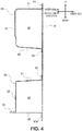
FIG. 4 is a sectional view taken along the line IV-IV inFIG. 1 ; -
FIG. 5 is a perspective view taken in the direction of arrow B inFIG. 2 ; -
FIG. 6 is a front view of a first reinforcing member; and -
FIG. 7 is a side view of essential portions of a front vehicle-body structure according to a variant. - Now, with reference to the accompanying drawings, an embodiment of the present invention will be described. In the description below, a front vehicle-body structure of a vehicle will be described for one side (right side) in a vehicle width direction, but the same applies to the other side (left side). In the drawings, directions such as "front/rear", "inner/outer", and "up/down" refer to a front-rear direction, a vehicle width direction, and a vertical direction, respectively, of the vehicle unless otherwise described.
- As shown in
FIGS. 1 and2 , a front vehicle-body structure 1 includes ahinge pillar 2 extending vertically in a front side part of a vehicle interior, anapron reinforcement 3 coupled to an upper part of thehinge pillar 2 and extending forward, particularly aside sill 4 coupled to a lower part of thehinge pillar 2 and extending rearward, and a bracingreinforcement 5 coupling theapron reinforcement 3 to thehinge pillar 2 in a bracing manner and particularly also to a front part of theside sill 4. - The
hinge pillar 2 particularly has a closed section extending vertically, and a front door (not shown) is openably/closably pivoted thereon. Theside sill 4 particularly has a closed section extending in the front-rear direction, and a front end of theside sill 4 protrudes forward of a lower end of thehinge pillar 2. - The front vehicle-
body structure 1 also includes particularly aside frame 7 extending in the front-rear direction below theapron reinforcement 3 particularly on an inner side in the vehicle width direction, and asuspension housing 6 spanning theapron reinforcement 3 and theside frame 7 in the vehicle width direction and supported. Thesuspension housing 6 is spaced forward from thehinge pillar 2, and houses a front suspension (not shown) therein (on a lower side). - A
side panel 8 is provided between a rear part of thesuspension housing 6 and thehinge pillar 2. Theside panel 8 extends in the vertical and front-rear directions, and defines an outer end of an engine room E in the vehicle width direction. - Below the bracing
reinforcement 5 and thesuspension housing 6, a wheel well 9 housing a front wheel is formed. A substantially intermediate part of the wheel well 9 in the front-rear direction is constituted by thesuspension housing 6. A rear part of thewheel well 9 includes a wheel well innerrear part 91 located particularly on the inner side in the vehicle width direction and a wheel well outerrear part 92 located on the outer side in the vehicle width direction with theside panel 8 therebetween. These rear parts are joined to a lower front part of theside panel 8 from opposite sides in the vehicle width direction by spot welding. The wheel well outerrear part 92 extends rearward so as to curve downward. - The
suspension housing 6 is particularly a member made of an aluminum alloy and including ahousing body 61, asuspension top 62 to which a damper (not shown) included in a front suspension is mounted from below, and ahousing shoulder 63 formed one step lower at an outer end of an upper part in the vehicle width direction, integrally formed, for example, by aluminum die casting. The damper (not shown) is mounted to the suspension top with its axis being inclined inward in the vehicle width direction toward an upper side in a front view of the vehicle. - The
housing shoulder 63 includes, on the outer side of thesuspension top 62 in the vehicle width direction, aninner flange 63a extending substantially horizontally in the front-rear direction, avertical wall 63b extending downward from an outer end of theinner flange 63a in the vehicle width direction, and anouter flange 63c extending from a lower end of thevertical wall 63b to the outer side in the vehicle width direction. Theouter flange 63c extends forward so as to curve upward, and forms an end of the wheel well 9 on the outer side in the vehicle width direction. -
FIG. 3 is an enlarged view, taken in the direction of arrow A inFIG. 2 , of a rear end upper part of thesuspension housing 6 seen from below. As shown inFIG. 3 , abase 64 expanding upward is formed at an upper end rear part of thehousing body 61. A top surface of thebase 64 has a planar shape inclined upward toward the inner side in the vehicle width direction and inclined outward in the vehicle width direction toward the front side. - As shown in
FIGS. 1 and2 , theapron reinforcement 3 is particularly divided in the front-rear direction into afront apron reinforcement 30 located on the front side and arear apron reinforcement 40 located on the rear side.FIG. 1 shows thefront apron reinforcement 30 in perspective by a two-dot chain line, andFIG. 2 shows thefront apron reinforcement 30 removed upward from the front vehicle-body structure 1 in partially perspective. - The
front apron reinforcement 30 particularly extends along thehousing shoulder 63 of thesuspension housing 6 in the front-rear direction. Therear apron reinforcement 40 particularly extends in the front-rear direction, and couples thefront apron reinforcement 30 and thehinge pillar 2 in the front-rear direction. - As shown in
FIG. 2 , a basic section of thefront apron reinforcement 30 perpendicular to the front-rear direction is particularly a hat-shaped section opening downward. Thefront apron reinforcement 30 includes anupper surface 31 extending substantially horizontally in the front-rear direction at a top, anouter surface 32 extending downward from an outer end of theupper surface 31 in the vehicle width direction, and aninner surface 33 extending downward from an inner end of the upper surface in the vehicle width direction. Theupper surface 31 constitutes an apron reinforcement upper wall in the present invention. - At a lower end of the
outer surface 32, anouter flange 34 extending outward in the vehicle width direction is particularly formed. Theinner surface 33 has anotch 36 cut in an inverted L shape in a rear lower part, and aninner flange 35 extending inward in the vehicle width direction is formed at a front lower end of thenotch 36. - The
front apron reinforcement 30 is joined, at theouter flange 34 and theinner flange 35, to thehousing shoulder 63 of thesuspension housing 6 from above, and joined, at thenotch 36 on the rear side, to theside panel 8 from the outer side in the vehicle width direction. - Specifically, the
front apron reinforcement 30 is joined, at theouter flange 34, to theouter flange 63c of thehousing shoulder 63 from above, joined, at theinner flange 35, to theinner flange 63a of thehousing shoulder 63 from above, and joined, at thenotch 36, to a front part of theside panel 8 from the inner side in the vehicle width direction. Thus, thefront apron reinforcement 30 together with thesuspension housing 6 and theside panel 8 constitutes a rectangular closed section S1 (seeFIG. 1 ) extending in the front-rear direction. - In the
outer surface 32 of thefront apron reinforcement 30, anotch 32a cut rearward in a squared U-shape is formed in a part of a rear edge closer to a lower side but except a lower end. In other words, the lower end of the rear edge of theouter surface 32 of thefront apron reinforcement 30 is not cut, but forms aprotrusion 32b protruding rearward of thenotch 32a. - A first reinforcing
member 70 is particularly provided at a rear end of thefront apron reinforcement 30. The first reinforcingmember 70 partitions the closed section S1 in the front-rear direction, thereby preventing crush of the section in the vertical and vehicle width directions. - The
suspension housing 6 is particularly a member made of an aluminium alloy, while other members joined to thesuspension housing 6 are made of steel plates. Thus, these members are joined by riveting (for example, self pierce riveting (SPR)). The members other than thesuspension housing 6 are formed by pressing steel plates, and the members made of steel plates are joined by spot welding. - As shown in
FIG. 4 , a section of therear apron reinforcement 40 perpendicular to the front-rear direction is a hat-shaped section opening inward in the vehicle width direction. Therear apron reinforcement 40 particularly includes a pair ofupper surface 41 andlower surface 42 extending substantially horizontally in the front-rear direction, and anouter surface 43 vertically connecting outer ends of theupper surface 41 and thelower surface 42 in the vehicle width direction. Theupper surface 41 has anupper flange 44 extending upward from an inner end in the vehicle width direction. Thelower surface 42 has alower flange 45 extending downward from an inner end in the vehicle width direction. Thelower surface 42 constitutes an apron reinforcement bottom wall in the present invention. - As shown in
FIG. 3 , therear apron reinforcement 40 is joined to the rear end of thefront apron reinforcement 30 from outside so as to overlap the rear end in the front-rear direction. Specifically, therear apron reinforcement 40 is joined, at a front end of theupper surface 41, to a rear end of theupper surface 31 of thefront apron reinforcement 30 from above by spot welding, and particularly joined at a front end of theouter surface 43, to a rear end of theouter surface 32 of thefront apron reinforcement 30 from the outer side in the vehicle width direction by spot welding. - The
outer surface 32 of thefront apron reinforcement 30 is vertically longer than theouter surface 43 of therear apron reinforcement 40, and thelower surface 42 of therear apron reinforcement 40 is located in thenotch 32a. Thus, theouter surface 43 of therear apron reinforcement 40 is located on the outer side in the vehicle width direction of theouter surface 32 of thefront apron reinforcement 30, and also interference between theouter surface 32 of thefront apron reinforcement 30 and thelower surface 42 of therear apron reinforcement 40 is avoided. - As shown in
FIG. 4 , therear apron reinforcement 40 is particularly joined, at the pair ofupper flange 45 and lower flange 46, to theside panel 8 from the outer side in the vehicle width direction by spot welding. Thus, therear apron reinforcement 40 together with theside panel 8 constitutes a rectangular closed section S2 extending in the front-rear direction, and the closed section S2 overlaps and is continuous with the closed section S1 of thefront apron reinforcement 30 in the front-rear direction. - As shown in
FIG. 1 , a second reinforcingmember 80 is particularly provided in the middle of therear apron reinforcement 40 in the front-rear direction. The second reinforcingmember 80 partitions the closed section S2 in the front-rear direction, thereby preventing crush of the section in the vertical and vehicle width directions. - As shown in
FIGS. 1 and2 , the bracingreinforcement 5 particularly includes a wheel well outerrear part 92 and a bracingmember 50. The bracingmember 50 extends rearward to be inclined downward. As shown inFIG. 4 , the bracingmember 50 has an L-shaped section and includes arear surface 51 facing the wheel well outerrear part 92 from an upper rear side, having a width in the vehicle width direction, and extending rearward to be inclined downward, and anouter surface 52 extending forward from an outer end of therear surface 51 in the vehicle width direction to be inclined downward. Therear surface 51 constitutes a bracing reinforcement top wall in the present invention. - The
rear surface 51 includes arear flange 53 extending rearward from an inner end in the vehicle width direction to be inclined upward, and anupper flange 54 extending forward from an upper end. Theouter surface 52 has afront flange 55 extending outward in the vehicle width direction from a front edge extending to be inclined forward and upward and along the wheel well outerrear part 92. - The bracing
member 50 is joined, at therear flange 53, to theside panel 8 from the inner side in the vehicle width direction, and joined, at thefront flange 55, to the outer end of the wheel well outerrear part 92 in the vehicle width direction from the rear side. - The
upper flange 54 of the bracingmember 50 is particularly joined to thelower surface 42 of therear apron reinforcement 40 from below by spot welding. Theouter surface 52 of the bracingmember 50 is joined, at an upper end, to a front lower part of theouter surface 43 of therear apron reinforcement 40 from the outer side in the vehicle width direction by spot welding, and joined, at a rear end lower part, to a front end lower part of thehinge pillar 2 and a front end upper part of theside sill 4 from the outer side in the vehicle width direction by spot welding. - As shown in
FIGS. 1 and4 , the wheel well outerrear part 92 is particularly spaced rearward from thesuspension housing 6, extends rearward so as to curve downward along an extending direction of theouter flange 63c of thesuspension housing 6, and constitutes a bracing reinforcement bottom wall in the present invention. The wheel well outerrear part 92 has, at an inner end in the vehicle width direction, aflange 92a extending forward or forward and downward. The wheel well outerrear part 92 is joined, at theflange 92a, to theside panel 8 from the outer side in the vehicle width direction by spot welding. - Thus, in the bracing
reinforcement 5, the bracingmember 50, the wheel well outerrear part 92, and theside panel 8 particularly form a closed section S3 extending rearward to be inclined downward. -
FIG. 5 is an enlarged view, taken in the direction of arrow B inFIG. 2 , of a first reinforcingmember 70 and therearound seen from the inner side in the vehicle width direction. Theside panel 8 and thefront apron reinforcement 30 are not shown. As shown inFIG. 5 , the first reinforcingmember 70 particularly has a squared U-shape opening rearward in a side view of the vehicle, and includes afront surface 71 facing in the front-rear direction, anupper surface 72 extending rearward from an upper end of thefront surface 71, and alower surface 73 extending rearward from a lower end of thefront surface 71 to be inclined downward. - The first reinforcing
member 70 further includes aninner flange 74 extending rearward or vertically from an inner end in the vehicle width direction into the squared U-shaped section, and anouter flange 75 extending rearward or vertically from an outer end in the vehicle width direction into the squared U-shaped section. - As shown in
FIGS. 5 and6 , the first reinforcingmember 70 further includes arecess 76 chamfered rearward in a part of a bend between thefront surface 71 and thelower surface 73 closer to a center or the vehicle or the inner side in the vehicle width direction. Therecess 76 particularly has a planar shape inclined upward toward the center or the vehicle or the inner side in the vehicle width direction, and inclined outward in the vehicle width direction toward the front of the vehicle or the front side. - The
front surface 71 particularly has anopening 71a extending therethrough in the front-rear direction. Theopening 71a has a vertically long elliptical shape, and an edge of the opening is cut and raised rearward like burring. This increases rigidity of thefront surface 71. - As shown in
FIGS. 1 and2 , the first reinforcingmember 70 is joined, at theupper surface 72, to the rear end of theupper surface 31 of thefront apron reinforcement 30 from below by spot welding, joined, at theouter flange 75, to the rear end of theouter surface 32 of thefront apron reinforcement 30 from inside or the inner side in the vehicle width direction by spot welding, and joined, at theinner flange 74, to theside panel 8 from the outer side in the vehicle width direction by spot welding. - A lower end of the
outer flange 75 of the first reinforcingmember 70 is particularly joined to theprotrusion 32b formed at the lower end in the rear edge of theouter surface 32 of thefront apron reinforcement 30 by spot welding. - As shown in
FIG. 5 , in the side view of the vehicle, theupper surface 72 and thelower surface 73 of the first reinforcingmember 70 overlap a front part of therear apron reinforcement 40 in the front-rear direction. - As shown in
FIG. 3 , the first reinforcingmember 70 is particularly joined, at a rear end of thelower surface 73, to an upper end of the wheel well outerrear part 92 from above by spot welding. Specifically, thelower surface 73 of the first reinforcingmember 70 forms an outer end of the wheel well 9 between thesuspension housing 6 and the wheel well outerrear part 92. - As shown in
FIG. 1 , theupper surface 31 of thefront apron reinforcement 30 and the wheel well outerrear part 92 are vertically coupled via the first reinforcingmember 70. Thus, the rear part of thefront apron reinforcement 30, therear apron reinforcement 40, the first reinforcingmember 70, and the bracingreinforcement 5 constitute a high rigidity portion in the form of thenumber 7 in the side view of the vehicle. - Further, as shown in
FIG. 5 , the first reinforcingmember 70 is particularly joined, at therecess 76, to thebase 64 of thesuspension housing 6 by riveting. As described above, therecess 76 and the base 64 are inclined upward toward the inner side in the vehicle width direction, and thus thesuspension housing 6 is joined to therecess 76 in a direction perpendicular to the inclination, that is, in a joining direction inclined downward toward the inner side in the vehicle width direction. - Thus, the suspension housing is joined to and supported by the first reinforcing
member 70 having higher rigidity in the high rigidity portion in the form of thenumber 7. Further, therecess 76 is chamfered in the bend of the first reinforcingmember 70 and thus has higher rigidity. To therecess 76, thesuspension housing 6 is joined substantially along an inward falling direction of the suspension housing (that is, the direction inclined downward toward the inner side in the vehicle width direction). This effectively prevents inward falling of thesuspension housing 6. - As shown in
FIG. 5 , a second reinforcingmember 80 is particularly located behind or on a rear side of the first reinforcingmember 70, and is a joint-like member including apartition wall 81 that partitions the inside of the closed section S2 of therear apron reinforcement 40 in the front-rear direction, anupper flange 82 and alower flange 83 extending forward from an upper end and a lower end, respectively, of thepartition wall 81, aninner flange 84 extending rearward from an inner end of thepartition wall 81 in the vehicle width direction, and anouter flange 85 extending forward from an outer end of thepartition wall 81 in the vehicle width direction. - The second reinforcing
member 80 is particularly joined, at theupper flange 82, to theupper surface 41 of therear apron reinforcement 40 from below by spot welding, joined, at thelower flange 83, to thelower surface 42 of therear apron reinforcement 40 from above by spot welding, joined, at theinner flange 84, to theside panel 8 from the outer side in the vehicle width direction by spot welding, and joined, at theouter flange 85, to theouter surface 43 of therear apron reinforcement 40 from the inner side in the vehicle width direction by spot welding. - The second reinforcing
member 80 is particularly located generally correspondingly to an upper end of the bracingmember 50 with thelower surface 42 of therear apron reinforcement 40 therebetween. Specifically, in the second reinforcingmember 80, thelower flange 83 is vertically continuous with theupper flange 54 of the bracingmember 50 with thelower surface 42 of therear apron reinforcement 40 therebetween for three-piece joining. - Thus, as shown in
FIG. 1 , the closed section S3 of the bracingreinforcement 5 enters the closed section S1 of thefront apron reinforcement 30 and the closed section S2 of the rear apron reinforcement from below via the first reinforcingmember 70 and the second reinforcingmember 80. - The front vehicle-
body structure 1 according to the embodiment particularly provides the following effects. - (1) The first reinforcing
member 70 is provided over the inside of the closed section S1 of thefront apron reinforcement 30 and the wheel well outerrear part 92 located at the bottom of the bracingreinforcement 5. Specifically, a rigid portion of the bracingreinforcement 5 extends into the closed section S1 of thefront apron reinforcement 30 without a break at thelower surface 42 of therear apron reinforcement 40.
The first reinforcingmember 70 prevents crush of the section of theapron reinforcement 3, thereby increasing rigidity of theapron reinforcement 3 itself and also increasing support rigidity of theapron reinforcement 3 with the bracingreinforcement 5. Thus, theapron reinforcement 3 having the increased support rigidity increases support rigidity of thesuspension housing 6, thereby effectively preventing inward falling of thesuspension housing 6. - (2) The first reinforcing
member 70 increases rigidity of the rear end of thefront apron reinforcement 30. Further, the rear end of thefront apron reinforcement 30 having the increased rigidity overlaps therear apron reinforcement 40 in the front-rear direction via the first reinforcingmember 70.
Thus, even if the first reinforcingmember 70 is vertically provided over the bracingreinforcement 5 and theapron reinforcement 3 to divide theapron reinforcement 3 into thefront apron reinforcement 30 and therear apron reinforcement 40 in the front-rear direction, a reduction in rigidity of theapron reinforcement 3 between thesuspension housing 6 and thehinge pillar 2 can be prevented.
Thus, rigidity of the bracingreinforcement 5 with the first reinforcingmember 70 can be increased, and also a reduction in rigidity of theapron reinforcement 3 can be prevented, thereby more effectively preventing inward falling of thesuspension housing 6. - (3) On the front side of the
hinge pillar 2, therear apron reinforcement 40 of theapron reinforcement 3 extending forward from thehinge pillar 2 to the reinforcing member, the first reinforcingmember 70, and the bracingreinforcement 5 constitute a high rigidity portion in the form of thenumber 7 in a side view. This further increases support rigidity of thesuspension housing 6 with theapron reinforcement 3. - (4) In the high rigidity portion in the form of the
number 7, the first reinforcingmember 70 supports the rear end of thesuspension housing 6, thereby further increasing support rigidity of thesuspension housing 6. - (5) The closed section S3 of the bracing
reinforcement 5 vertically extends inside the closed sections S1, S2 of theapron reinforcement 3 via the first reinforcingmember 70 and also the second reinforcingmember 80. As a result, the high rigidity portion formed by the closed section S3 of the bracingreinforcement 5 is configured to enter the closed sections S1, S2 of theapron reinforcement 3, thereby further increasing support rigidity of theapron reinforcement 3 with the bracingreinforcement 5. This further increases support rigidity of theapron reinforcement 3 with the bracingreinforcement 5, and theapron reinforcement 3 having the increased support rigidity further increases support rigidity of thesuspension housing 6, thereby further effectively preventing inward falling of thesuspension housing 6. - In the embodiment, the first reinforcing
member 70 is joined, at theupper surface 72, to theupper surface 31 of thefront apron reinforcement 30 from below. In addition, the front part of theupper surface 41 of therear apron reinforcement 40 may be abutted to theupper surface 31 of thefront apron reinforcement 30 from above for three-piece joining. This further increases rigidity of theapron reinforcement 3. - Further, as shown in
FIG. 7 , an upper part of theouter surface 52 of the bracingmember 50 may be extended forward and thus joined to theprotrusion 32b formed in theouter surface 32 of thefront apron reinforcement 30 from the outer side in the vehicle width direction. In this case, as hatched inFIG. 7 , the upper part of theouter surface 52 and theprotrusion 32b may be further joined to theouter flange 75 of the first reinforcingmember 70 for three-piece joining. This further increases support rigidity of theapron reinforcement 3 with the bracingreinforcement 5. - As described above, with the front vehicle-body structure according to the present invention, increasing support rigidity of the apron reinforcement with the bracing reinforcement can prevent inward falling deformation of the suspension housing. Thus, the front vehicle-body structure can be favorably used in this type of manufacturing technology field.
Claims (15)
- A front vehicle-body structure (1) comprising:a hinge pillar (2) extending vertically;a suspension housing (6) spaced forward from the hinge pillar (2);an apron reinforcement (3) that extends forward from an upper part of the hinge pillar (2), has a closed section perpendicular to a front-rear direction, and is configured to support the suspension housing (6);a bracing reinforcement (5) that extends rearward to be inclined downward so as to couple the apron reinforcement (3) and the hinge pillar (2) in a bracing manner below the apron reinforcement (3), and has a closed section perpendicular to a direction of the extension; anda reinforcing member (70) that is provided inside the closed section of the apron reinforcement (3) and configured to partition the closed section in the front-rear direction,wherein the bracing reinforcement (5) includes, at a bottom, a bracing reinforcement bottom wall (92) extending rearward to be inclined downward, and the reinforcing member (70) is connected to the bracing reinforcement bottom wall (92).
- The front vehicle-body structure (1) according to claim 1, wherein the apron reinforcement (3) includes a front apron reinforcement (30) configured to support the suspension housing (6), and a rear apron reinforcement (40) configured to couple a rear end of the front apron reinforcement (30) and the hinge pillar (2), and
the reinforcing member (70) is provided at the rear end of the front apron reinforcement (30), and overlaps a front part of the rear apron reinforcement (40) in the front-rear direction in a side view of a vehicle. - The front vehicle-body structure (1) according to claim 1 or 2, wherein the apron reinforcement (3) includes, at an upper part, an apron reinforcement upper wall (31) extending substantially horizontally, and
the reinforcing member (70) includes an upper flange that extends rearward from an upper end and is connected to the apron reinforcement upper wall (31), and a lower flange that extends rearward from a lower end and is connected to the bracing reinforcement bottom wall (92). - The front vehicle-body structure (1) according to any one of the preceding claims, wherein the reinforcing member (70) is configured to support a rear end of the suspension housing (6).
- The front vehicle-body structure (1) according to any one of the preceding claims, wherein the reinforcing member (70) is a first reinforcing member (70),
inside the closed section of the apron reinforcement (3), a second reinforcing member (80) configured to partition the closed section in the front-rear direction is further provided behind, or on a rear side of, the first reinforcing member (70),
the bracing reinforcement (5) includes, at a top, a bracing reinforcement top wall (51) facing the bracing reinforcement bottom wall (92) from above and back, or an upper rear side,
the apron reinforcement (3) includes, at a bottom, an apron reinforcement bottom wall (42) extending substantially horizontally, and
the bracing reinforcement top wall (51) is vertically continuous with a lower end of the second reinforcing member (80) via the apron reinforcement bottom wall (42). - The front vehicle-body structure (1) according to any one of the preceding claims, wherein the bracing reinforcement (5) is configured to further couple the apron reinforcement (3) to a side sill (4).
- The front vehicle-body structure (1) according to any one of the preceding claims, further comprising a side frame (7) extending in the front-rear direction below the apron reinforcement (3).
- The front vehicle-body structure (1) according to claim 7, wherein the suspension housing (6) is provided between the apron reinforcement (3) and the side frame (7) .
- The front vehicle-body structure (1) according to any one of the preceding claims, further comprising a side panel (8) provided between a rear part of the suspension housing (6) and the hinge pillar (2).
- The front vehicle-body structure (1) according to claim 9 referring back to claim 2, wherein the rear apron reinforcement (40) together with the side panel (8) is configured to constitute a closed section (S2).
- The front vehicle-body structure (1) according to claim 10, wherein the closed section (S2) constituted by the rear apron reinforcement (40) and the side panel (8) is configured to overlap and/or be continuous with a closed section (S1) of the front apron reinforcement (30) .
- The front vehicle-body structure (1) according to any one of the preceding claims, wherein the apron reinforcement (3) is configured to extend along the suspension housing (6) in the front-rear direction.
- The front vehicle-body structure (1) according to any one of the preceding claims, wherein the apron reinforcement (3) is at least partially hat-shaped.
- The front vehicle-body structure (1) according to any one of the preceding claims, wherein the reinforcing member (70) is joined to the suspension housing (6).
- A vehicle comprising a front vehicle-body structure (1) according to any one of the preceding claims.
Applications Claiming Priority (1)
| Application Number | Priority Date | Filing Date | Title |
|---|---|---|---|
| JP2018179230A JP6977692B2 (en) | 2018-09-25 | 2018-09-25 | Front body structure |
Publications (2)
| Publication Number | Publication Date |
|---|---|
| EP3632778A1 true EP3632778A1 (en) | 2020-04-08 |
| EP3632778B1 EP3632778B1 (en) | 2021-06-09 |
Family
ID=67874290
Family Applications (1)
| Application Number | Title | Priority Date | Filing Date |
|---|---|---|---|
| EP19195529.3A Active EP3632778B1 (en) | 2018-09-25 | 2019-09-05 | Front vehicle-body structure and vehicle |
Country Status (4)
| Country | Link |
|---|---|
| US (1) | US11077883B2 (en) |
| EP (1) | EP3632778B1 (en) |
| JP (1) | JP6977692B2 (en) |
| CN (1) | CN110937023B (en) |
Cited By (1)
| Publication number | Priority date | Publication date | Assignee | Title |
|---|---|---|---|---|
| EP4289708A1 (en) * | 2022-06-06 | 2023-12-13 | Toyota Jidosha Kabushiki Kaisha | Body for vehicle, and battery electric vehicle |
Families Citing this family (2)
| Publication number | Priority date | Publication date | Assignee | Title |
|---|---|---|---|---|
| DE102020205576A1 (en) * | 2020-05-04 | 2021-11-04 | Volkswagen Aktiengesellschaft | Body structure for a vehicle |
| CN114435481B (en) * | 2020-11-02 | 2023-04-25 | 本田技研工业(中国)投资有限公司 | B column for vehicle |
Citations (5)
| Publication number | Priority date | Publication date | Assignee | Title |
|---|---|---|---|---|
| EP1886902A1 (en) * | 2006-08-09 | 2008-02-13 | Nissan Motor Co., Ltd. | Vehicle front structure |
| JP2015096349A (en) * | 2013-11-15 | 2015-05-21 | マツダ株式会社 | Front body structure of the vehicle |
| JP2016112914A (en) * | 2014-12-11 | 2016-06-23 | マツダ株式会社 | Front vehicle body structure |
| JP2017128228A (en) | 2016-01-20 | 2017-07-27 | マツダ株式会社 | Front body structure of the vehicle |
| WO2018016174A1 (en) * | 2016-07-21 | 2018-01-25 | 本田技研工業株式会社 | Vehicle chassis front section structure |
Family Cites Families (10)
| Publication number | Priority date | Publication date | Assignee | Title |
|---|---|---|---|---|
| JPH0542717Y2 (en) * | 1987-06-26 | 1993-10-27 | ||
| JPH02246877A (en) * | 1989-03-20 | 1990-10-02 | Mazda Motor Corp | Front body structure for automobile |
| JP5573607B2 (en) * | 2010-11-04 | 2014-08-20 | スズキ株式会社 | Reinforcement structure at the front of the car body |
| JP5640934B2 (en) * | 2011-09-13 | 2014-12-17 | 三菱自動車工業株式会社 | Front body structure of the vehicle |
| JP5998619B2 (en) * | 2012-05-09 | 2016-09-28 | マツダ株式会社 | Rear body structure of the vehicle |
| JP6369445B2 (en) * | 2015-10-23 | 2018-08-08 | マツダ株式会社 | Front body structure of automobile |
| JP6432535B2 (en) * | 2016-01-20 | 2018-12-05 | マツダ株式会社 | Front body structure of the vehicle |
| JP6372494B2 (en) * | 2016-01-20 | 2018-08-15 | マツダ株式会社 | Front body structure of the vehicle |
| JP6504063B2 (en) * | 2016-01-20 | 2019-04-24 | マツダ株式会社 | Front body structure of the vehicle |
| JP6269758B1 (en) * | 2016-09-13 | 2018-01-31 | マツダ株式会社 | Front body structure of the vehicle |
-
2018
- 2018-09-25 JP JP2018179230A patent/JP6977692B2/en active Active
-
2019
- 2019-09-05 EP EP19195529.3A patent/EP3632778B1/en active Active
- 2019-09-13 US US16/570,601 patent/US11077883B2/en active Active
- 2019-09-16 CN CN201910869762.8A patent/CN110937023B/en active Active
Patent Citations (5)
| Publication number | Priority date | Publication date | Assignee | Title |
|---|---|---|---|---|
| EP1886902A1 (en) * | 2006-08-09 | 2008-02-13 | Nissan Motor Co., Ltd. | Vehicle front structure |
| JP2015096349A (en) * | 2013-11-15 | 2015-05-21 | マツダ株式会社 | Front body structure of the vehicle |
| JP2016112914A (en) * | 2014-12-11 | 2016-06-23 | マツダ株式会社 | Front vehicle body structure |
| JP2017128228A (en) | 2016-01-20 | 2017-07-27 | マツダ株式会社 | Front body structure of the vehicle |
| WO2018016174A1 (en) * | 2016-07-21 | 2018-01-25 | 本田技研工業株式会社 | Vehicle chassis front section structure |
Cited By (2)
| Publication number | Priority date | Publication date | Assignee | Title |
|---|---|---|---|---|
| EP4289708A1 (en) * | 2022-06-06 | 2023-12-13 | Toyota Jidosha Kabushiki Kaisha | Body for vehicle, and battery electric vehicle |
| US12428070B2 (en) | 2022-06-06 | 2025-09-30 | Toyota Jidosha Kabushiki Kaisha | Body for vehicle, and battery electric vehicle |
Also Published As
| Publication number | Publication date |
|---|---|
| US11077883B2 (en) | 2021-08-03 |
| CN110937023B (en) | 2022-05-24 |
| JP2020050032A (en) | 2020-04-02 |
| US20200094880A1 (en) | 2020-03-26 |
| CN110937023A (en) | 2020-03-31 |
| EP3632778B1 (en) | 2021-06-09 |
| JP6977692B2 (en) | 2021-12-08 |
Similar Documents
| Publication | Publication Date | Title |
|---|---|---|
| EP1084937B1 (en) | Vehicle body structure | |
| US20200047818A1 (en) | Lower vehicle-body structure | |
| CN100584681C (en) | Subbody structure of a vehicle with sliding doors | |
| EP3632778B1 (en) | Front vehicle-body structure and vehicle | |
| CN111434569B (en) | Vehicle body lower structure | |
| JP6181099B2 (en) | Rear structure of the car body | |
| EP2058212B1 (en) | Vehicle equipped with passenger frame having small height from ground | |
| CN112455546A (en) | Subframe for vehicle | |
| JP2017128224A (en) | Vehicle front part vehicle body structure | |
| EP3718863B1 (en) | Vehicle side body structure, and vehicle | |
| JP5639936B2 (en) | Body side structure | |
| EP2783950A1 (en) | Vehicle body side section structure | |
| JP4894629B2 (en) | Car locker reinforcement structure | |
| JP2003002236A (en) | Car body superstructure | |
| JP3765244B2 (en) | Car body rear structure | |
| EP1741619B1 (en) | Underbody structure of sliding-door vehicle | |
| US11529999B2 (en) | Vehicle | |
| JP2010234955A (en) | Car body rear structure | |
| JP2017128299A (en) | Vehicle body structure | |
| JP3275751B2 (en) | Undercar front pillar structure | |
| JP7590392B2 (en) | Front pillar lower | |
| US11420682B2 (en) | Vehicle-body structure of vehicle | |
| JP6414551B2 (en) | Front body structure of the vehicle | |
| JP3109310B2 (en) | Side member structure | |
| JP7372894B2 (en) | Vehicle rear structure |
Legal Events
| Date | Code | Title | Description |
|---|---|---|---|
| PUAI | Public reference made under article 153(3) epc to a published international application that has entered the european phase |
Free format text: ORIGINAL CODE: 0009012 |
|
| STAA | Information on the status of an ep patent application or granted ep patent |
Free format text: STATUS: THE APPLICATION HAS BEEN PUBLISHED |
|
| AK | Designated contracting states |
Kind code of ref document: A1 Designated state(s): AL AT BE BG CH CY CZ DE DK EE ES FI FR GB GR HR HU IE IS IT LI LT LU LV MC MK MT NL NO PL PT RO RS SE SI SK SM TR |
|
| AX | Request for extension of the european patent |
Extension state: BA ME |
|
| STAA | Information on the status of an ep patent application or granted ep patent |
Free format text: STATUS: REQUEST FOR EXAMINATION WAS MADE |
|
| 17P | Request for examination filed |
Effective date: 20200903 |
|
| RBV | Designated contracting states (corrected) |
Designated state(s): AL AT BE BG CH CY CZ DE DK EE ES FI FR GB GR HR HU IE IS IT LI LT LU LV MC MK MT NL NO PL PT RO RS SE SI SK SM TR |
|
| GRAP | Despatch of communication of intention to grant a patent |
Free format text: ORIGINAL CODE: EPIDOSNIGR1 |
|
| STAA | Information on the status of an ep patent application or granted ep patent |
Free format text: STATUS: GRANT OF PATENT IS INTENDED |
|
| RIC1 | Information provided on ipc code assigned before grant |
Ipc: B62D 25/08 20060101AFI20210118BHEP |
|
| INTG | Intention to grant announced |
Effective date: 20210202 |
|
| GRAS | Grant fee paid |
Free format text: ORIGINAL CODE: EPIDOSNIGR3 |
|
| GRAA | (expected) grant |
Free format text: ORIGINAL CODE: 0009210 |
|
| STAA | Information on the status of an ep patent application or granted ep patent |
Free format text: STATUS: THE PATENT HAS BEEN GRANTED |
|
| AK | Designated contracting states |
Kind code of ref document: B1 Designated state(s): AL AT BE BG CH CY CZ DE DK EE ES FI FR GB GR HR HU IE IS IT LI LT LU LV MC MK MT NL NO PL PT RO RS SE SI SK SM TR |
|
| REG | Reference to a national code |
Ref country code: GB Ref legal event code: FG4D |
|
| REG | Reference to a national code |
Ref country code: CH Ref legal event code: EP Ref country code: AT Ref legal event code: REF Ref document number: 1400256 Country of ref document: AT Kind code of ref document: T Effective date: 20210615 |
|
| REG | Reference to a national code |
Ref country code: DE Ref legal event code: R096 Ref document number: 602019005218 Country of ref document: DE |
|
| REG | Reference to a national code |
Ref country code: IE Ref legal event code: FG4D |
|
| REG | Reference to a national code |
Ref country code: LT Ref legal event code: MG9D |
|
| PG25 | Lapsed in a contracting state [announced via postgrant information from national office to epo] |
Ref country code: LT Free format text: LAPSE BECAUSE OF FAILURE TO SUBMIT A TRANSLATION OF THE DESCRIPTION OR TO PAY THE FEE WITHIN THE PRESCRIBED TIME-LIMIT Effective date: 20210609 Ref country code: HR Free format text: LAPSE BECAUSE OF FAILURE TO SUBMIT A TRANSLATION OF THE DESCRIPTION OR TO PAY THE FEE WITHIN THE PRESCRIBED TIME-LIMIT Effective date: 20210609 Ref country code: FI Free format text: LAPSE BECAUSE OF FAILURE TO SUBMIT A TRANSLATION OF THE DESCRIPTION OR TO PAY THE FEE WITHIN THE PRESCRIBED TIME-LIMIT Effective date: 20210609 Ref country code: BG Free format text: LAPSE BECAUSE OF FAILURE TO SUBMIT A TRANSLATION OF THE DESCRIPTION OR TO PAY THE FEE WITHIN THE PRESCRIBED TIME-LIMIT Effective date: 20210909 |
|
| REG | Reference to a national code |
Ref country code: AT Ref legal event code: MK05 Ref document number: 1400256 Country of ref document: AT Kind code of ref document: T Effective date: 20210609 |
|
| REG | Reference to a national code |
Ref country code: NL Ref legal event code: MP Effective date: 20210609 |
|
| PG25 | Lapsed in a contracting state [announced via postgrant information from national office to epo] |
Ref country code: GR Free format text: LAPSE BECAUSE OF FAILURE TO SUBMIT A TRANSLATION OF THE DESCRIPTION OR TO PAY THE FEE WITHIN THE PRESCRIBED TIME-LIMIT Effective date: 20210910 Ref country code: LV Free format text: LAPSE BECAUSE OF FAILURE TO SUBMIT A TRANSLATION OF THE DESCRIPTION OR TO PAY THE FEE WITHIN THE PRESCRIBED TIME-LIMIT Effective date: 20210609 Ref country code: NO Free format text: LAPSE BECAUSE OF FAILURE TO SUBMIT A TRANSLATION OF THE DESCRIPTION OR TO PAY THE FEE WITHIN THE PRESCRIBED TIME-LIMIT Effective date: 20210909 Ref country code: RS Free format text: LAPSE BECAUSE OF FAILURE TO SUBMIT A TRANSLATION OF THE DESCRIPTION OR TO PAY THE FEE WITHIN THE PRESCRIBED TIME-LIMIT Effective date: 20210609 Ref country code: SE Free format text: LAPSE BECAUSE OF FAILURE TO SUBMIT A TRANSLATION OF THE DESCRIPTION OR TO PAY THE FEE WITHIN THE PRESCRIBED TIME-LIMIT Effective date: 20210609 |
|
| PG25 | Lapsed in a contracting state [announced via postgrant information from national office to epo] |
Ref country code: CZ Free format text: LAPSE BECAUSE OF FAILURE TO SUBMIT A TRANSLATION OF THE DESCRIPTION OR TO PAY THE FEE WITHIN THE PRESCRIBED TIME-LIMIT Effective date: 20210609 Ref country code: AT Free format text: LAPSE BECAUSE OF FAILURE TO SUBMIT A TRANSLATION OF THE DESCRIPTION OR TO PAY THE FEE WITHIN THE PRESCRIBED TIME-LIMIT Effective date: 20210609 Ref country code: SM Free format text: LAPSE BECAUSE OF FAILURE TO SUBMIT A TRANSLATION OF THE DESCRIPTION OR TO PAY THE FEE WITHIN THE PRESCRIBED TIME-LIMIT Effective date: 20210609 Ref country code: NL Free format text: LAPSE BECAUSE OF FAILURE TO SUBMIT A TRANSLATION OF THE DESCRIPTION OR TO PAY THE FEE WITHIN THE PRESCRIBED TIME-LIMIT Effective date: 20210609 Ref country code: RO Free format text: LAPSE BECAUSE OF FAILURE TO SUBMIT A TRANSLATION OF THE DESCRIPTION OR TO PAY THE FEE WITHIN THE PRESCRIBED TIME-LIMIT Effective date: 20210609 Ref country code: PT Free format text: LAPSE BECAUSE OF FAILURE TO SUBMIT A TRANSLATION OF THE DESCRIPTION OR TO PAY THE FEE WITHIN THE PRESCRIBED TIME-LIMIT Effective date: 20211011 Ref country code: EE Free format text: LAPSE BECAUSE OF FAILURE TO SUBMIT A TRANSLATION OF THE DESCRIPTION OR TO PAY THE FEE WITHIN THE PRESCRIBED TIME-LIMIT Effective date: 20210609 Ref country code: ES Free format text: LAPSE BECAUSE OF FAILURE TO SUBMIT A TRANSLATION OF THE DESCRIPTION OR TO PAY THE FEE WITHIN THE PRESCRIBED TIME-LIMIT Effective date: 20210609 Ref country code: SK Free format text: LAPSE BECAUSE OF FAILURE TO SUBMIT A TRANSLATION OF THE DESCRIPTION OR TO PAY THE FEE WITHIN THE PRESCRIBED TIME-LIMIT Effective date: 20210609 |
|
| PG25 | Lapsed in a contracting state [announced via postgrant information from national office to epo] |
Ref country code: PL Free format text: LAPSE BECAUSE OF FAILURE TO SUBMIT A TRANSLATION OF THE DESCRIPTION OR TO PAY THE FEE WITHIN THE PRESCRIBED TIME-LIMIT Effective date: 20210609 |
|
| REG | Reference to a national code |
Ref country code: DE Ref legal event code: R097 Ref document number: 602019005218 Country of ref document: DE |
|
| REG | Reference to a national code |
Ref country code: DE Ref legal event code: R119 Ref document number: 602019005218 Country of ref document: DE |
|
| PLBE | No opposition filed within time limit |
Free format text: ORIGINAL CODE: 0009261 |
|
| STAA | Information on the status of an ep patent application or granted ep patent |
Free format text: STATUS: NO OPPOSITION FILED WITHIN TIME LIMIT |
|
| PG25 | Lapsed in a contracting state [announced via postgrant information from national office to epo] |
Ref country code: DK Free format text: LAPSE BECAUSE OF FAILURE TO SUBMIT A TRANSLATION OF THE DESCRIPTION OR TO PAY THE FEE WITHIN THE PRESCRIBED TIME-LIMIT Effective date: 20210609 |
|
| 26N | No opposition filed |
Effective date: 20220310 |
|
| REG | Reference to a national code |
Ref country code: BE Ref legal event code: MM Effective date: 20210930 |
|
| PG25 | Lapsed in a contracting state [announced via postgrant information from national office to epo] |
Ref country code: MC Free format text: LAPSE BECAUSE OF FAILURE TO SUBMIT A TRANSLATION OF THE DESCRIPTION OR TO PAY THE FEE WITHIN THE PRESCRIBED TIME-LIMIT Effective date: 20210609 Ref country code: AL Free format text: LAPSE BECAUSE OF FAILURE TO SUBMIT A TRANSLATION OF THE DESCRIPTION OR TO PAY THE FEE WITHIN THE PRESCRIBED TIME-LIMIT Effective date: 20210609 |
|
| PG25 | Lapsed in a contracting state [announced via postgrant information from national office to epo] |
Ref country code: LU Free format text: LAPSE BECAUSE OF NON-PAYMENT OF DUE FEES Effective date: 20210905 Ref country code: IT Free format text: LAPSE BECAUSE OF FAILURE TO SUBMIT A TRANSLATION OF THE DESCRIPTION OR TO PAY THE FEE WITHIN THE PRESCRIBED TIME-LIMIT Effective date: 20210609 Ref country code: IE Free format text: LAPSE BECAUSE OF NON-PAYMENT OF DUE FEES Effective date: 20210905 Ref country code: FR Free format text: LAPSE BECAUSE OF NON-PAYMENT OF DUE FEES Effective date: 20210930 Ref country code: DE Free format text: LAPSE BECAUSE OF NON-PAYMENT OF DUE FEES Effective date: 20220401 Ref country code: BE Free format text: LAPSE BECAUSE OF NON-PAYMENT OF DUE FEES Effective date: 20210930 |
|
| REG | Reference to a national code |
Ref country code: CH Ref legal event code: PL |
|
| PG25 | Lapsed in a contracting state [announced via postgrant information from national office to epo] |
Ref country code: CY Free format text: LAPSE BECAUSE OF FAILURE TO SUBMIT A TRANSLATION OF THE DESCRIPTION OR TO PAY THE FEE WITHIN THE PRESCRIBED TIME-LIMIT Effective date: 20210609 |
|
| PG25 | Lapsed in a contracting state [announced via postgrant information from national office to epo] |
Ref country code: LI Free format text: LAPSE BECAUSE OF NON-PAYMENT OF DUE FEES Effective date: 20220930 Ref country code: HU Free format text: LAPSE BECAUSE OF FAILURE TO SUBMIT A TRANSLATION OF THE DESCRIPTION OR TO PAY THE FEE WITHIN THE PRESCRIBED TIME-LIMIT; INVALID AB INITIO Effective date: 20190905 Ref country code: CH Free format text: LAPSE BECAUSE OF NON-PAYMENT OF DUE FEES Effective date: 20220930 |
|
| PG25 | Lapsed in a contracting state [announced via postgrant information from national office to epo] |
Ref country code: MK Free format text: LAPSE BECAUSE OF FAILURE TO SUBMIT A TRANSLATION OF THE DESCRIPTION OR TO PAY THE FEE WITHIN THE PRESCRIBED TIME-LIMIT Effective date: 20210609 |
|
| GBPC | Gb: european patent ceased through non-payment of renewal fee |
Effective date: 20230905 |
|
| PG25 | Lapsed in a contracting state [announced via postgrant information from national office to epo] |
Ref country code: TR Free format text: LAPSE BECAUSE OF FAILURE TO SUBMIT A TRANSLATION OF THE DESCRIPTION OR TO PAY THE FEE WITHIN THE PRESCRIBED TIME-LIMIT Effective date: 20210609 |
|
| PG25 | Lapsed in a contracting state [announced via postgrant information from national office to epo] |
Ref country code: GB Free format text: LAPSE BECAUSE OF NON-PAYMENT OF DUE FEES Effective date: 20230905 |
|
| PG25 | Lapsed in a contracting state [announced via postgrant information from national office to epo] |
Ref country code: GB Free format text: LAPSE BECAUSE OF NON-PAYMENT OF DUE FEES Effective date: 20230905 |
|
| PG25 | Lapsed in a contracting state [announced via postgrant information from national office to epo] |
Ref country code: MT Free format text: LAPSE BECAUSE OF FAILURE TO SUBMIT A TRANSLATION OF THE DESCRIPTION OR TO PAY THE FEE WITHIN THE PRESCRIBED TIME-LIMIT Effective date: 20210609 |