EP3632669A1 - Heat-press system - Google Patents
Heat-press system Download PDFInfo
- Publication number
- EP3632669A1 EP3632669A1 EP19196612.6A EP19196612A EP3632669A1 EP 3632669 A1 EP3632669 A1 EP 3632669A1 EP 19196612 A EP19196612 A EP 19196612A EP 3632669 A1 EP3632669 A1 EP 3632669A1
- Authority
- EP
- European Patent Office
- Prior art keywords
- roll
- heat
- fabric
- press system
- core
- Prior art date
- Legal status (The legal status is an assumption and is not a legal conclusion. Google has not performed a legal analysis and makes no representation as to the accuracy of the status listed.)
- Granted
Links
Images



Classifications
-
- B—PERFORMING OPERATIONS; TRANSPORTING
- B29—WORKING OF PLASTICS; WORKING OF SUBSTANCES IN A PLASTIC STATE IN GENERAL
- B29D—PRODUCING PARTICULAR ARTICLES FROM PLASTICS OR FROM SUBSTANCES IN A PLASTIC STATE
- B29D35/00—Producing footwear
- B29D35/0054—Producing footwear by compression moulding, vulcanising or the like; Apparatus therefor
-
- B—PERFORMING OPERATIONS; TRANSPORTING
- B29—WORKING OF PLASTICS; WORKING OF SUBSTANCES IN A PLASTIC STATE IN GENERAL
- B29C—SHAPING OR JOINING OF PLASTICS; SHAPING OF MATERIAL IN A PLASTIC STATE, NOT OTHERWISE PROVIDED FOR; AFTER-TREATMENT OF THE SHAPED PRODUCTS, e.g. REPAIRING
- B29C65/00—Joining or sealing of preformed parts, e.g. welding of plastics materials; Apparatus therefor
- B29C65/48—Joining or sealing of preformed parts, e.g. welding of plastics materials; Apparatus therefor using adhesives, i.e. using supplementary joining material; solvent bonding
- B29C65/4805—Joining or sealing of preformed parts, e.g. welding of plastics materials; Apparatus therefor using adhesives, i.e. using supplementary joining material; solvent bonding characterised by the type of adhesives
- B29C65/481—Non-reactive adhesives, e.g. physically hardening adhesives
- B29C65/4815—Hot melt adhesives, e.g. thermoplastic adhesives
-
- A—HUMAN NECESSITIES
- A41—WEARING APPAREL
- A41D—OUTERWEAR; PROTECTIVE GARMENTS; ACCESSORIES
- A41D27/00—Details of garments or of their making
- A41D27/24—Hems; Seams
- A41D27/245—Hems; Seams made by welding or gluing
-
- B—PERFORMING OPERATIONS; TRANSPORTING
- B29—WORKING OF PLASTICS; WORKING OF SUBSTANCES IN A PLASTIC STATE IN GENERAL
- B29C—SHAPING OR JOINING OF PLASTICS; SHAPING OF MATERIAL IN A PLASTIC STATE, NOT OTHERWISE PROVIDED FOR; AFTER-TREATMENT OF THE SHAPED PRODUCTS, e.g. REPAIRING
- B29C65/00—Joining or sealing of preformed parts, e.g. welding of plastics materials; Apparatus therefor
- B29C65/02—Joining or sealing of preformed parts, e.g. welding of plastics materials; Apparatus therefor by heating, with or without pressure
-
- B—PERFORMING OPERATIONS; TRANSPORTING
- B29—WORKING OF PLASTICS; WORKING OF SUBSTANCES IN A PLASTIC STATE IN GENERAL
- B29C—SHAPING OR JOINING OF PLASTICS; SHAPING OF MATERIAL IN A PLASTIC STATE, NOT OTHERWISE PROVIDED FOR; AFTER-TREATMENT OF THE SHAPED PRODUCTS, e.g. REPAIRING
- B29C65/00—Joining or sealing of preformed parts, e.g. welding of plastics materials; Apparatus therefor
- B29C65/02—Joining or sealing of preformed parts, e.g. welding of plastics materials; Apparatus therefor by heating, with or without pressure
- B29C65/18—Joining or sealing of preformed parts, e.g. welding of plastics materials; Apparatus therefor by heating, with or without pressure using heated tools
-
- B—PERFORMING OPERATIONS; TRANSPORTING
- B29—WORKING OF PLASTICS; WORKING OF SUBSTANCES IN A PLASTIC STATE IN GENERAL
- B29D—PRODUCING PARTICULAR ARTICLES FROM PLASTICS OR FROM SUBSTANCES IN A PLASTIC STATE
- B29D35/00—Producing footwear
-
- B—PERFORMING OPERATIONS; TRANSPORTING
- B29—WORKING OF PLASTICS; WORKING OF SUBSTANCES IN A PLASTIC STATE IN GENERAL
- B29D—PRODUCING PARTICULAR ARTICLES FROM PLASTICS OR FROM SUBSTANCES IN A PLASTIC STATE
- B29D35/00—Producing footwear
- B29D35/0009—Producing footwear by injection moulding; Apparatus therefor
- B29D35/0018—Moulds
-
- B—PERFORMING OPERATIONS; TRANSPORTING
- B30—PRESSES
- B30B—PRESSES IN GENERAL
- B30B3/00—Presses characterised by the use of rotary pressing members, e.g. rollers, rings, discs
- B30B3/005—Roll constructions
-
- B—PERFORMING OPERATIONS; TRANSPORTING
- B29—WORKING OF PLASTICS; WORKING OF SUBSTANCES IN A PLASTIC STATE IN GENERAL
- B29L—INDEXING SCHEME ASSOCIATED WITH SUBCLASS B29C, RELATING TO PARTICULAR ARTICLES
- B29L2031/00—Other particular articles
- B29L2031/48—Wearing apparel
-
- B—PERFORMING OPERATIONS; TRANSPORTING
- B29—WORKING OF PLASTICS; WORKING OF SUBSTANCES IN A PLASTIC STATE IN GENERAL
- B29L—INDEXING SCHEME ASSOCIATED WITH SUBCLASS B29C, RELATING TO PARTICULAR ARTICLES
- B29L2031/00—Other particular articles
- B29L2031/48—Wearing apparel
- B29L2031/50—Footwear, e.g. shoes or parts thereof
Definitions
- the present invention relates to a heat-press system for the production of footwear or apparel, and methods for producing footwear or apparel.
- a heat-press system for use in the production of footwear or apparel, comprising: at least a first hollow roll comprising an external surface and an internal surface, the internal surface defining a core, wherein the core comprises a first heating element.
- the term "hollow” means that the empty, unfilled first roll itself is at least partly hollow, i.e. that it comprises a cavity or core, defined by an external surface and an internal surface of the first roll.
- the cavity or core does not have to extend of a whole length of the first roll.
- the first core may extend over at least 50% of a length of the first roll, preferably at least 75%. This enables a uniform transmission of heat from the core to the external surface.
- the first core may be formed by a milling process, starting from a solid essentially cylindrical workpiece, e.g. a piece of metal, e.g. a rod.
- the core comprises a first heating element which partially or entirely fills the core. It is also possible that additional elements are arranged in the core. In other words, the term hollow is not to be construed in such a way that it requires an empty core of the first roll or a core that comprises only the first heating element.
- the first roll may, for example, be essentially cylindrical.
- the term "essentially cylindrical” is to be understood such that the external surface is cylindrical in a topological sense.
- the essentially cylindrical external surface may have a variable radius, due to manufacturing imperfections or to selectively compress certain regions of a fabric, of an article of footwear or apparel, more than others.
- the essentially cylindrical external surface may also comprise a texture, in order to impart a texture onto the fabric.
- a "fabric” in the present context may be any textile, for example a weft-knitted textile, warp-knitted textile, a woven textile, a non-woven textile, a leather etc.
- the heat-press system allows the simultaneous application of heat and compression of the fabric for an article of apparel or footwear in a single process step, for example for sealing a cutting edge of the fabric or for creating a reinforcement region of increased bending stiffness. Therefore, the number of steps required is reduced compared with methods that employ an apparatus, e.g. a press, as known in the art, thus reducing the complexity.
- a bonding agent may be applied to the fabric for the article of apparel or footwear, as described elsewhere herein.
- the fabric may comprise a meltable yarn, that may have a melting temperature of less than 200°C, preferably less than 150°C.
- the risk of misalignment for example of a hotmelt applied to the fabric, is reduced by combining the steps of heating and applying pressure.
- the first roll may comprise a material with a thermal conductivity greater than 10 W/mK, preferably greater than 50 W/mK, most preferably greater than 100 W/mK. It is to be understood that the thermal conductivity is to be measured using standard techniques at 273.15 K and at a pressure of 1 bar, also known as standard temperature and pressure (STP). Therefore, heat generated by the first heating element is conducted well from the first core to the external surface.
- Suitable materials for the first roll include, for example, stainless steel, copper, steel, aluminium, other metals, a polymer or plastic with the given thermal conductivity, combinations thereof, and other suitable materials. These materials have a desirable thermal conductivity and provide good abrasion resistance.
- the first roll may further comprise a first thermometer.
- the first thermometer may be detachable to allow easy replacement of broken thermometers.
- the first thermometer could be any device suitable for measuring temperature on a relative or absolute scale by any suitable method. For example, a thermocouple would be suitable.
- the first thermometer therefore allows the temperature of the first roll to be determined, in order to allow selecting a temperature that is sufficiently high in order to melt the bonding agent and/or the meltable yarn, yet that is not too high, such that damage to the fabric may be prevented.
- the thermometer may be arranged between the heating element and the external surface to allow an accurate determination of the temperature.
- the heating element may comprise a first electrically-conducting wire.
- the first electrically-conducting wire may comprise a metal alloy comprising iron, nickel, chromium, copper, manganese, and/or cobalt. Such alloys have a high melting temperature and have a fairly constant specific electrical resistivity over a large temperature range, allowing a safe operation and easy control of the temperature.
- electrically conducting is understood in its usual sense, i.e. materials can be classified into electrical conductors, semiconductors, and electrical insulators.
- the first roll may comprise a coil, which comprises the first electrically-conducting wire.
- a coil which comprises the first electrically-conducting wire.
- the first electrically-conducting wire is preferably arranged in the shape of a coil, in order to save space and to provide a sufficient dissipation of heat to the external surface.
- the electrically-conducting wire may comprise an electrical insulation with a thermal conductivity greater than 5 W/mK.
- the electrical insulation preferably comprises a thermal conductivity greater than 5 W/mK, more preferably 10 W/mK, most preferably 15 W/mK.
- the electrical insulation may be applied as a coating to the electrically-conducting wire.
- the surface of the wire comprises an oxide, for example a magnesium oxide that serves as electrical insulation. This arrangement is particularly space-efficient.
- the electrical insulation may be take up a substantial part of the volume of the core, for example at least 10%, preferably at least 25%, most preferably at least 40%, for example as a filler, which fills essentially all available space in the first core. The inventors have found, that this improves the thermal contact between the first heating element and the external surface. It is possible that a first material is used as a coating and a different second material is used to create a strong thermal bond surrounding the insulated electrically-conducting wire.
- the electrical insulation i.e. the first and / or the second material
- the electrically-conducting wire needs to be electrically insulated.
- many electrical insulators are poor thermal conductors since poor electrical conductors tend to be poor thermal conductors and vice versa.
- the electrical insulation may comprise a magnesium oxide.
- a magnesium oxide may allow a particularly high thermal conductivity, between 45 and 60 W/mK, therefore allowing a particularly good thermal contact between the first heating element and the external surface.
- the external surface of the first roll may comprise a first circumferential indentation or a first circumferential projection.
- An indentation may be a groove. This may improve the alignment of a fabric and may prevent unintended lateral movement of the fabric during the procedure.
- the heat-press system may further comprise an abutting surface configured to form a compression zone with the external surface of the first roll for compressing a fabric for an article footwear or apparel.
- an abutting surface does not need to make direct contact with the first roll.
- the fabric will be arranged at least partially between the first roll and the abutting surface in the compression zone.
- an abutting surface may be advantageous but is not essential for the operation of the heat-press system.
- the heat-press system is used to simultaneously apply heat and pressure to a fabric held under tension, without the presence of an abutting surface.
- the external surface of the first roll and / or the abutting surface may be coupled to a biasing mechanism.
- a biasing mechanism, or suspension mechanism may be biased, or pre-loaded.
- the coupling may be direct or may involve one or more intermediate elements.
- the first roll may be moveable over a sled, with the contact force adjusted by the biasing mechanism.
- the biasing mechanism allows the relative position of the first and the abutting surface to be controlled. Therefore, the force exerted by the external surface and the abutting surface on a fabric may be controlled. This is particularly useful, because it means that the heat-press system may be used for different thicknesses of fabric and / or bonding agent without requiring any adjustment. Moreover, too much force, or pressure, may damage the fabric, which may be prevented by the biasing mechanism.
- the biasing mechanism may allow an essentially-linear displacement, and/or a rotary displacement.
- the biasing mechanism may comprise a spring.
- a spring allows a simple and durable construction of a biasing mechanism, allowing both essentially-linear displacement as well as rotary displacement.
- a rubber pad and / or rubber shock may be used additionally and or alternatively, for example for setting a desired compression force.
- the heat-press system may further comprise a second roll, wherein the second roll comprises an external surface, and wherein the external surface forms the abutting surface of the heat press system.
- the inventors have found, that using the first roll and the second roll allows for particularly high production speeds.
- the abutting surface may be essentially flat.
- the second roll may further comprise an internal surface, the internal surface defining a second core, the second core comprising a second heating element.
- the inventors have found, that it is advantageous for a uniform application of heat, for the fabric and / or the bonding agent to be heated from both sides, i.e. by the first roll and the second roll.
- the second roll may have similar or identical properties to the first roll as described herein.
- At least one of the first roll and the abutting surface may comprise a projection. Only one of the first roll and the abutting surface may comprise a projection.
- both the first roll and the abutting surface may comprise a projection.
- a projection is useful to prevent unintended slipping of the fabric during use of the heat-press system. It is not necessary for the other one of the first roll and the abutting surface to comprise a corresponding groove.
- the other one of the first roll and the abutting surface may comprise a groove wherein the projection is configured to be inserted into the groove when the first roll and the abutting surface abut.
- the first roll may comprise a groove and the abutting surface, e.g. the second roll, may comprise a corresponding projection.
- the first roll may comprise a projection and the abutting surface, e.g. the second roll, may comprise a corresponding groove.
- the first roll may comprise a first projection and a second groove and the abutting surface, e.g. the second roll, may comprise a first groove corresponding to the first projection and a second projection corresponding to the second groove.
- the groove(s) may form a path for the fabric and/or the bonding agent to pass through. Therefore, this arrangement advantageously improves the alignment of the fabric and the bonding agent, especially before the fabric and/or the bonding agent solidifies.
- the projection and / or the groove may be arranged circumferentially around the first and / or the second roll. This allows for a particularly simple and reliable processing.
- the heat-press system may further comprise at least one motor, wherein the first roll is rotatable about a first axis and / or the second roll is rotatable about a second axis, by means of the motor.
- a single motor may be used to rotate the first roll and the second roll.
- a first motor may be used to rotate the first roll and a second motor may be used to rotate the second roll.
- a motor may be controlled precisely electronically and may be preferable compared with hand-operated rotation, in order to automate the process and prevent worker fatigue.
- the heat-press system may further comprise a guiding means to guide a fabric for a piece of footwear or apparel toward the compression zone located between the first roll and the abutting surface, e.g. the second roll.
- the guiding means, or feeder may be used to ensure that a bonding agent is correctly aligned before being arranged on the fabric, for example on the edge of the fabric, and before the fabric, and bonding agent if present, enter the compression zone.
- the guiding means may comprise a material with a thermal conductivity greater than 10 W/mK, preferably greater than 50 W/mK, most preferably greater than 100 W/mK.
- Suitable materials include, for example, stainless steel, copper, steel, aluminium, and other metals. These materials have a desirable thermal conductivity and provide good abrasion resistance.
- the guiding means may comprise a third heating element. Therefore, the guiding means may pre-heat the fabric and/or the bonding agent. This may increase production speed as a shorter compression time, during which the fabric is compressed in-between the external surface and the abutting surface, may be required.
- the guiding means may comprise a third thermometer, in order to ensure that a suitable temperature, that is neither too high, nor too low, is set.
- the guiding means may comprise a first guiding surface and a second guiding surface arranged in a V-shaped configuration.
- the first and/or the second guiding surface may be essentially flat.
- a V-shaped configuration is understood as any configuration in which the first and the second guiding surfaces are arranged at an angle between 5° and 150°, preferably between 20° and 120°, which may help to pre-fold the bonding agent around the fabric.
- the heat-press system may further comprise at least one control unit to control the temperature of the first, second (if present), and / or third (if present) heating element.
- a first control unit may control the temperature of the first heating element
- the second control unit may control the temperature of the second heating element
- a third control unit may control the temperature of the third heating element.
- a single control unit may control the temperature of all three heating elements.
- the inventors have found that it is important to accurately control the temperature of the heating elements in order to prevent damage to the fabric and / or to prevent any meltable material, for example the bonding agent and / or the meltable yarn, from sticking to the heat-press system.
- the temperature needs to be sufficiently high in order to melt the bonding agent and/or the meltable yarn.
- the least one control unit may allow the temperature of the first roll, the second roll and/or the guiding means to be controlled to better than i°C precision preferably better than 0.5°C precision.
- the heat-press system may be for sealing an edge of a fabric.
- the inventors have found that the heat-press system is particularly useful for sealing the edge of a fabric, e.g. a cutting edge since it the fabric to be compressed and heated in a single process step thus simplifying the production and reducing the likelihood of errors due to misalignment.
- Sealing the edge of the fabric may comprise the use of a hotmelt, a ribbon, or a seam tape.
- a seam tape and / or a ribbon may comprise a hotmelt.
- a seam tape is configured to fit around the edge of a seam in order to allow the seam to be sealed. This allows a precise and localized bond to be achieved.
- the invention further concerns a method of treating a fabric for an article of footwear or apparel, comprising applying a bonding agent, which melts or softens upon application of heat, to the fabric and / or incorporating a meltable yarn into the fabric, and feeding the fabric into the heat-press system according to the present invention.
- a bonding agent may be any material that melts or softens upon application of heat, preferably at less than 200° C, more preferably at less than 150° C.
- a hotmelt or a metal or metal alloy with a low melting temperature for example an alloy comprising tin, is a bonding agent.
- a meltable yarn may be incorporated by any known method, for example stitching, knitting, weaving etc.
- the present method offers a reduced number of process steps and thus a reduced complexity compared to methods known in the art. Furthermore, the production time may also be reduced compared to techniques known in the art.
- the feeding of the fabric into the heat-press system may comprise: (c) heating at least a first portion the fabric and / or the bonding agent by heating at least one of the first, second (if present), or third (if present) heating element, and (d) compressing at least a second portion of the fabric in the compression zone.
- the first portion and the second portion may overlap partially or entirely. Therefore, the benefits of the heat-press system described herein are fully exploited.
- the bonding agent and / or the meltable yarn may comprise a thermoplastic polymer.
- the bonding agent and / or the meltable yarn may comprise thermoplastic polyurethane, which has excellent adhesive properties and is non-toxic.
- the bonding agent may have the shape of a seam tape, a ribbon or a film.
- the shape allows a particularly simple and accurate placement of the bonding agent on the fabric.
- the placement may be performed by an automated setup, such as a patch-placement machine.
- the bonding agent may be applied to an edge of the fabric. This may help to prevent fraying and tearing, which might otherwise result at the edge of the fabric due to lose cut fibers or yarns.
- applying a ribbon may comprise folding the ribbon over the cut edge.
- the fabric may be for an upper of an article of footwear.
- the bonding agent may be used around the collar opening of an upper for an article of footwear.
- the collar opening is subject to significant stresses during exercise and therefore the method according to the present invention not only prevents fraying but may also increase the bending stiffness of the upper around the collar opening, thus increasing stability.
- the invention further concerns an article of footwear or apparel comprising a fabric produced by method according to the present invention.
- An article of footwear may be any shoe, especially a sports shoe, such as a football boot, a running shoe, a basketball boot, a golf shoe, tennis shoe, hiking shoe, a hiking boot, etc.
- An apparel may be any type of apparel, especially sports apparel, for example a shirt, a jersey, shorts, trousers, a cap, etc.
- An article of footwear or apparel produced by a method according to the present invention is less prone to manufacturing defects such as inaccurately aligned sealing elements, e.g. hotmelt patches than those known in the art. As a result, an article of footwear or apparel according to the present invention is also more durable than those known in the art.
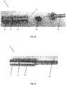
- Figs. 1A-B show an exemplary heat-press system 21 for use in the production of footwear or apparel, comprising: at least a hollow first roll 11 comprising an external surface 12 and an internal surface 19, the internal surface 19 defining a core 16, wherein the core 16 comprises a first heating element 13.
- the external surface 12 is essentially cylindrical.
- the first roll 11 comprises a material with a thermal conductivity greater than 10 W/mK. at 273.15 K and at a pressure of 1 bar, also known as standard temperature and pressure (STP).
- the first roll 11 comprises stainless steel.
- the first core 16 extends over more than 50% of a length of the first roll.
- the first roll 11 is attached to a separate mount 14, which is to facilitate mounting the first roll 11 in a heat-press system 21 as described with reference to Figs. 2 and 4 .
- the first heating element 13 comprises a first electrically-conducting wire, wound up as a coil, which comprises the first electrically-conducting wire.
- the wire comprises an alloy comprising about 55 % copper, 44% nickel, and 1 % manganese, sometimes also referred to as Constantan® or Konstantan®.
- the electrically-conducting wire comprises an electrical insulation with a thermal conductivity greater than 5 W/mK.
- the electrical insulation is applied as a coating on the electrically-conducting wire. This arrangement is particularly space-efficient.
- the electrical insulation comprises a magnesium oxide, which allows a particularly high thermal conductivity, between 45 and 60 W/mK, therefore allowing a particularly good thermal contact between the first heating element 13 and the external surface 12.
- the external surface 12 of the first roll 11 comprises a first circumferential groove 15.
- Figs. 1A-B show an example in which the electrical insulation is only applied as a coating on the electrically-conducting wire.
- Fig. 1C shows a cross-section of a first roll 11 according to another embodiment.
- the first roll 11 comprises an external surface 12 and an internal surface 19 configured to form a first core 16.
- the first core 16 comprises a heating element 13.
- the first core 16 comprises an electrically insulating but thermally conducting filler material 17, which fills substantially the entire available volume in the core 16.
- the filler material 17 takes up more than 40% of the volume of the core 16.
- the first roll 11 further comprises a first thermometer 18, arranged between the first heating element 13 and the first core 16.
- the first thermometer 18 is detachable to allow easy replacement of broken thermometers.
- a thermocouple is used as first thermometer 18.
- Fig. 2 shows another exemplary heat-press system 21 according to the present invention.
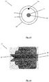
- Fig. 2A shows the general arrangement of the heat-press system 21, while Fig. 2B shows a cross-section of the second roll 22.
- the heat-press system 21 is for use in the production of footwear or apparel and comprises: a hollow first roll 11 comprising an external surface 12 and an internal surface (not shown), the internal surface defining a core (not shown), wherein the core comprises a first heating element.
- the heat-press system 21 further comprises an abutting surface 24 configured to form a compression zone 29 with the external surface 12 of the first roll 11 for compressing a fabric for an article footwear or apparel (not shown).
- the external surface 12 of the roll 11 is coupled to a biasing mechanism 25.
- the biasing mechanism 25 allows an essentially-linear displacement.
- the biasing mechanism 25 may allow a rotary displacement.
- the biasing mechanism 25 comprises a spring, which is attached to a base 27.
- a rubber pad and / or rubber shock may be used.
- the heat-press system 21 further comprises a second roll 22.
- the second roll 22 comprises an external surface 24, and wherein the external surface 24 forms the abutting surface 24 of the heat press system.
- Fig. 2B shows a cross-section of the second roll 22.
- the second roll 22 further comprises an internal surface 51, the internal surface 51 defining a second core 52, the second core 52 comprising a second heating element 53 and a second thermometer 54.
- the second heating element 53 comprises a second electrically-conducting wire, wound up as a coil, which comprises the second electrically-conducting wire.
- the second electrically-conducting wire comprises an insulation applied as a coating.
- the second core 52 does not comprise a filler material. It is, however, possible that the second core also comprises a filler material. Likewise, it is also possible the first core shown in Fig. 1C does not comprise a filler material.
- the first roll 11 comprises a groove 15 and the abutting surface 24 comprises a corresponding projection 23, wherein the projection 23 is configured to be inserted into the groove 15 when the first roll 11 and the abutting surface 24 abut.
- the first roll 11 may not comprise a groove while the abutting surface 24 still comprises a projection, or vice versa.
- the first roll 11 comprises a first projection and a second groove and the abutting surface 24, e.g. the second roll, comprises a first groove corresponding to the first projection and a second projection corresponding to the second groove.
- the projection 23 is arranged to circumferentially extend around the second roll 22, while the groove 15 is arranged to circumferentially extend around the first roll 11.
- the groove 15 therefore forms a path for the fabric and/or the bonding agent to pass through.
- Figs. 3A and 3B show an exemplary guiding means 31 for a heat-press system 21 according to the present invention.
- the guiding means 31 guides a fabric toward the compression zone 29 located between the external surface 12 and the abutting surface 24.
- the guiding means 31, or feeder may be used to ensure that a bonding agent is correctly aligned before being arranged on the fabric, for example the edge of the fabric or a fiber, and before the fabric and/or bonding agent enters the compression zone 29.
- the guiding means 31 comprises a material with a thermal conductivity greater than 10 W/mK.
- the guiding means 31 comprises stainless steel.
- the guiding means 31 comprises a third heating element 13. Therefore, the guiding means 31 may pre-heat the fabric and/or the bonding agent. In the example of Fig. 3B , the guiding means 31 does not comprise a heating element.
- the guiding means 31 comprises a first guiding surface 32 and a second guiding surface 33 arranged in a V-shaped configuration.
- the guiding surfaces are longer than in the example of Fig. 3B .
- the first 32 and/or the second 33 guiding surfaces are essentially flat in both examples.
- Fig. 4 shows another exemplary heat-press system 21 according to the present invention.
- the heat-press system 21 is similar to the heat-press system 21 described with reference to Fig. 2 but additionally comprises a guiding means 31, for example as described with reference to Figs. 3A-B .
- the arrow labelled with reference numeral 28 indicates the direction in which a fabric to which a bonding agent may have been applied would be inserted into the heat-press.
- the exemplary heat-press system 21 further comprises a motor and control unit 34.
- the second roll 22 is rotatable about a second by means of the motor.
- a first motor may be used to rotate the first roll 11 and a second motor may be used to rotate the second roll 22.
- the control unit controls the temperature of the first and the second heating element.
- the exemplary control unit allows the temperature of the first roll 11 and the second roll 22 to be controlled to better than 0.5°C precision.
- Figs. 5A-B illustrate an exemplary method according to the present invention.
- Fig. 5A shows an exemplary fabric for an upper 41 of an article of footwear.
- the upper 41 comprises a plurality of yarns 43. Some the yarns are loose around the collar opening 42 of the upper, due to previous processing steps such as cutting.
- a seam tape comprising a bonding agent 44, which melts or softens upon application of heat has been applied.
- the melting temperature of the exemplary bonding agent is about 130° C.
- the bonding agent 44 is a hotmelt.
- the bonding agent comprises thermoplastic polyurethane, which has excellent adhesive properties and is non-toxic.
- the shoe upper with the bonding agent applied will then be fed into the heat-press system 21 described herein in order to seal the collar opening.
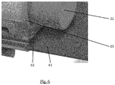
- Fig. 6 shows the consolidation of a seam by a method and apparatus according to the present invention including the use of a seam tape.
- Fig. 6 shows how a piece of fabric 61 is fed into the heat-press system according to the present invention.
- a seam tape 62 has been applied to an edge of the fabric 61.
- the seam tape is arranged such as to be pressed by projection 23 of the second roll 22 into a corresponding groove in the first roll (not shown). This allows the seam tape 62 to be held firmly in place while pressure and heat are being applied in order to prevent an unintended misalignment of the seam tape 62.
Landscapes
- Engineering & Computer Science (AREA)
- Mechanical Engineering (AREA)
- Textile Engineering (AREA)
- Footwear And Its Accessory, Manufacturing Method And Apparatuses (AREA)
- Treatment Of Fiber Materials (AREA)
Abstract
Description
- The present invention relates to a heat-press system for the production of footwear or apparel, and methods for producing footwear or apparel.
- In the production of fabric for footwear or apparel, it is frequently necessary to seal a cutting edge to prevent fraying or tearing. Presently, this involves a process in which a hotmelt is applied to the fabric in a first step, exposed to heat in a second step, and subjected to pressure in a third step. In other words, presently there are at least three separate steps required for sealing a fabric with hotmelt. It is therefore an object underlying the present invention, to provide a method and apparatus to reduce the number of steps required for sealing a fabric. A reduced number of steps, reduces the complexity of the method and may reduce the time for production and thus the cost of an item of apparel or footwear.
- Moreover, since the application of heat and pressure are separate steps, there is a risk that the softened hotmelt becomes misaligned after being exposed to heat and prior to being subjected to pressure. Therefore, a reduction in the number of process steps may also reduce the risk of misalignment and thus the amount of fabric that has to be disposed off due to production faults.
- Processes according to the prior art are described in
WO 2009/ 027 701 A1 ,GB 1 049 522 A US 4 737 212 A andWO 2007/ 122 661 A1 . - This object is accomplished by the teachings of the independent claims, in particular by a heat-press system for use in the production of footwear or apparel, comprising: at least a first hollow roll comprising an external surface and an internal surface, the internal surface defining a core, wherein the core comprises a first heating element.
- The term "hollow" means that the empty, unfilled first roll itself is at least partly hollow, i.e. that it comprises a cavity or core, defined by an external surface and an internal surface of the first roll. The cavity or core does not have to extend of a whole length of the first roll. The first core may extend over at least 50% of a length of the first roll, preferably at least 75%. This enables a uniform transmission of heat from the core to the external surface. For example, the first core may be formed by a milling process, starting from a solid essentially cylindrical workpiece, e.g. a piece of metal, e.g. a rod.
- However, the core comprises a first heating element which partially or entirely fills the core. It is also possible that additional elements are arranged in the core. In other words, the term hollow is not to be construed in such a way that it requires an empty core of the first roll or a core that comprises only the first heating element.
- The first roll may, for example, be essentially cylindrical. The term "essentially cylindrical" is to be understood such that the external surface is cylindrical in a topological sense. The essentially cylindrical external surface may have a variable radius, due to manufacturing imperfections or to selectively compress certain regions of a fabric, of an article of footwear or apparel, more than others. The essentially cylindrical external surface may also comprise a texture, in order to impart a texture onto the fabric. A "fabric" in the present context may be any textile, for example a weft-knitted textile, warp-knitted textile, a woven textile, a non-woven textile, a leather etc.
- The heat-press system allows the simultaneous application of heat and compression of the fabric for an article of apparel or footwear in a single process step, for example for sealing a cutting edge of the fabric or for creating a reinforcement region of increased bending stiffness. Therefore, the number of steps required is reduced compared with methods that employ an apparatus, e.g. a press, as known in the art, thus reducing the complexity. For example, a bonding agent may be applied to the fabric for the article of apparel or footwear, as described elsewhere herein. Alternatively, or additionally, the fabric may comprise a meltable yarn, that may have a melting temperature of less than 200°C, preferably less than 150°C. Moreover, the risk of misalignment, for example of a hotmelt applied to the fabric, is reduced by combining the steps of heating and applying pressure.
- The first roll may comprise a material with a thermal conductivity greater than 10 W/mK, preferably greater than 50 W/mK, most preferably greater than 100 W/mK. It is to be understood that the thermal conductivity is to be measured using standard techniques at 273.15 K and at a pressure of 1 bar, also known as standard temperature and pressure (STP). Therefore, heat generated by the first heating element is conducted well from the first core to the external surface. Suitable materials for the first roll include, for example, stainless steel, copper, steel, aluminium, other metals, a polymer or plastic with the given thermal conductivity, combinations thereof, and other suitable materials. These materials have a desirable thermal conductivity and provide good abrasion resistance.
- The first roll may further comprise a first thermometer. The first thermometer may be detachable to allow easy replacement of broken thermometers. The first thermometer could be any device suitable for measuring temperature on a relative or absolute scale by any suitable method. For example, a thermocouple would be suitable. The first thermometer therefore allows the temperature of the first roll to be determined, in order to allow selecting a temperature that is sufficiently high in order to melt the bonding agent and/or the meltable yarn, yet that is not too high, such that damage to the fabric may be prevented. The thermometer may be arranged between the heating element and the external surface to allow an accurate determination of the temperature.
- The heating element may comprise a first electrically-conducting wire. This allows a safe and controllable generation of heat by Joule heating. For example, the first electrically-conducting wire may comprise a metal alloy comprising iron, nickel, chromium, copper, manganese, and/or cobalt. Such alloys have a high melting temperature and have a fairly constant specific electrical resistivity over a large temperature range, allowing a safe operation and easy control of the temperature. The term "electrically conducting" is understood in its usual sense, i.e. materials can be classified into electrical conductors, semiconductors, and electrical insulators.
- The first roll may comprise a coil, which comprises the first electrically-conducting wire. To generate a preferable amount of heat, it may be required to use a first electrically-conducting wire that has a length much greater than a longitudinal length of the first roll, in order to prevent overheating of the first electrically-conducting wire. Therefore, the first electrically-conducting wire is preferably arranged in the shape of a coil, in order to save space and to provide a sufficient dissipation of heat to the external surface.
- The electrically-conducting wire may comprise an electrical insulation with a thermal conductivity greater than 5 W/mK. The inventors have found, that to ensure an effective application of heat by the first roll, the electrical insulation preferably comprises a thermal conductivity greater than 5 W/mK, more preferably 10 W/mK, most preferably 15 W/mK.
- The electrical insulation may be applied as a coating to the electrically-conducting wire. It is also possible that the surface of the wire comprises an oxide, for example a magnesium oxide that serves as electrical insulation. This arrangement is particularly space-efficient. Alternatively, or additionally the electrical insulation may be take up a substantial part of the volume of the core, for example at least 10%, preferably at least 25%, most preferably at least 40%, for example as a filler, which fills essentially all available space in the first core. The inventors have found, that this improves the thermal contact between the first heating element and the external surface. It is possible that a first material is used as a coating and a different second material is used to create a strong thermal bond surrounding the insulated electrically-conducting wire.
- The electrical insulation, i.e. the first and / or the second material, may comprise a ceramic, for example porcelain, a glass, quartz, mica, chamotte, silica, alumina, and / or steatite. Any of these materials may be in the form of a powder, a solid, or a potting compound. In order to prevent a short circuit, the electrically-conducting wire needs to be electrically insulated. However, many electrical insulators are poor thermal conductors since poor electrical conductors tend to be poor thermal conductors and vice versa.
- The electrical insulation may comprise a magnesium oxide. A magnesium oxide may allow a particularly high thermal conductivity, between 45 and 60 W/mK, therefore allowing a particularly good thermal contact between the first heating element and the external surface.
- The external surface of the first roll may comprise a first circumferential indentation or a first circumferential projection. An indentation may be a groove. This may improve the alignment of a fabric and may prevent unintended lateral movement of the fabric during the procedure.
- The heat-press system may further comprise an abutting surface configured to form a compression zone with the external surface of the first roll for compressing a fabric for an article footwear or apparel.
- It is to be understood that an abutting surface does not need to make direct contact with the first roll. Typically, the fabric will be arranged at least partially between the first roll and the abutting surface in the compression zone.
- It is to be understood that the presence of an abutting surface may be advantageous but is not essential for the operation of the heat-press system. For example, it is possible that the heat-press system is used to simultaneously apply heat and pressure to a fabric held under tension, without the presence of an abutting surface.
- The external surface of the first roll and / or the abutting surface may be coupled to a biasing mechanism. A biasing mechanism, or suspension mechanism may be biased, or pre-loaded. The coupling may be direct or may involve one or more intermediate elements. For example, the first roll may be moveable over a sled, with the contact force adjusted by the biasing mechanism. The biasing mechanism allows the relative position of the first and the abutting surface to be controlled. Therefore, the force exerted by the external surface and the abutting surface on a fabric may be controlled. This is particularly useful, because it means that the heat-press system may be used for different thicknesses of fabric and / or bonding agent without requiring any adjustment. Moreover, too much force, or pressure, may damage the fabric, which may be prevented by the biasing mechanism.
- The biasing mechanism may allow an essentially-linear displacement, and/or a rotary displacement.
- The biasing mechanism may comprise a spring. A spring allows a simple and durable construction of a biasing mechanism, allowing both essentially-linear displacement as well as rotary displacement. A rubber pad and / or rubber shock may be used additionally and or alternatively, for example for setting a desired compression force.
- The heat-press system may further comprise a second roll, wherein the second roll comprises an external surface, and wherein the external surface forms the abutting surface of the heat press system. The inventors have found, that using the first roll and the second roll allows for particularly high production speeds. Alternatively, the abutting surface may be essentially flat.
- The second roll may further comprise an internal surface, the internal surface defining a second core, the second core comprising a second heating element. The inventors have found, that it is advantageous for a uniform application of heat, for the fabric and / or the bonding agent to be heated from both sides, i.e. by the first roll and the second roll.
- Generally, the second roll may have similar or identical properties to the first roll as described herein.
- At least one of the first roll and the abutting surface may comprise a projection. Only one of the first roll and the abutting surface may comprise a projection.
- Alternatively, both the first roll and the abutting surface may comprise a projection. The inventors have found, that a projection is useful to prevent unintended slipping of the fabric during use of the heat-press system. It is not necessary for the other one of the first roll and the abutting surface to comprise a corresponding groove.
- The other one of the first roll and the abutting surface may comprise a groove wherein the projection is configured to be inserted into the groove when the first roll and the abutting surface abut. In other words, the first roll may comprise a groove and the abutting surface, e.g. the second roll, may comprise a corresponding projection. Alternatively, the first roll may comprise a projection and the abutting surface, e.g. the second roll, may comprise a corresponding groove. Alternatively, the first roll may comprise a first projection and a second groove and the abutting surface, e.g. the second roll, may comprise a first groove corresponding to the first projection and a second projection corresponding to the second groove. Thus, the groove(s) may form a path for the fabric and/or the bonding agent to pass through. Therefore, this arrangement advantageously improves the alignment of the fabric and the bonding agent, especially before the fabric and/or the bonding agent solidifies.
- The projection and / or the groove may be arranged circumferentially around the first and / or the second roll. This allows for a particularly simple and reliable processing.
- The heat-press system may further comprise at least one motor, wherein the first roll is rotatable about a first axis and / or the second roll is rotatable about a second axis, by means of the motor. A single motor may be used to rotate the first roll and the second roll. Alternatively, a first motor may be used to rotate the first roll and a second motor may be used to rotate the second roll. A motor may be controlled precisely electronically and may be preferable compared with hand-operated rotation, in order to automate the process and prevent worker fatigue.
- The heat-press system may further comprise a guiding means to guide a fabric for a piece of footwear or apparel toward the compression zone located between the first roll and the abutting surface, e.g. the second roll.
- The guiding means, or feeder, may be used to ensure that a bonding agent is correctly aligned before being arranged on the fabric, for example on the edge of the fabric, and before the fabric, and bonding agent if present, enter the compression zone.
- The guiding means may comprise a material with a thermal conductivity greater than 10 W/mK, preferably greater than 50 W/mK, most preferably greater than 100 W/mK. Suitable materials include, for example, stainless steel, copper, steel, aluminium, and other metals. These materials have a desirable thermal conductivity and provide good abrasion resistance.
- The guiding means may comprise a third heating element. Therefore, the guiding means may pre-heat the fabric and/or the bonding agent. This may increase production speed as a shorter compression time, during which the fabric is compressed in-between the external surface and the abutting surface, may be required. The guiding means may comprise a third thermometer, in order to ensure that a suitable temperature, that is neither too high, nor too low, is set.
- The guiding means may comprise a first guiding surface and a second guiding surface arranged in a V-shaped configuration. The first and/or the second guiding surface may be essentially flat. A V-shaped configuration is understood as any configuration in which the first and the second guiding surfaces are arranged at an angle between 5° and 150°, preferably between 20° and 120°, which may help to pre-fold the bonding agent around the fabric.
- The heat-press system may further comprise at least one control unit to control the temperature of the first, second (if present), and / or third (if present) heating element. For example, a first control unit may control the temperature of the first heating element, the second control unit may control the temperature of the second heating element and a third control unit may control the temperature of the third heating element. Alternatively, a single control unit may control the temperature of all three heating elements. The inventors have found that it is important to accurately control the temperature of the heating elements in order to prevent damage to the fabric and / or to prevent any meltable material, for example the bonding agent and / or the meltable yarn, from sticking to the heat-press system. On the other hand, the temperature needs to be sufficiently high in order to melt the bonding agent and/or the meltable yarn. For example, the least one control unit may allow the temperature of the first roll, the second roll and/or the guiding means to be controlled to better than i°C precision preferably better than 0.5°C precision.
- The heat-press system may be for sealing an edge of a fabric. The inventors have found that the heat-press system is particularly useful for sealing the edge of a fabric, e.g. a cutting edge since it the fabric to be compressed and heated in a single process step thus simplifying the production and reducing the likelihood of errors due to misalignment.
- Sealing the edge of the fabric may comprise the use of a hotmelt, a ribbon, or a seam tape. A seam tape and / or a ribbon may comprise a hotmelt. A seam tape is configured to fit around the edge of a seam in order to allow the seam to be sealed. This allows a precise and localized bond to be achieved.
- The invention further concerns a method of treating a fabric for an article of footwear or apparel, comprising applying a bonding agent, which melts or softens upon application of heat, to the fabric and / or incorporating a meltable yarn into the fabric, and feeding the fabric into the heat-press system according to the present invention.
- A bonding agent may be any material that melts or softens upon application of heat, preferably at less than 200° C, more preferably at less than 150° C. For example, a hotmelt or a metal or metal alloy with a low melting temperature, for example an alloy comprising tin, is a bonding agent. A meltable yarn may be incorporated by any known method, for example stitching, knitting, weaving etc.
- The present method offers a reduced number of process steps and thus a reduced complexity compared to methods known in the art. Furthermore, the production time may also be reduced compared to techniques known in the art.
- The feeding of the fabric into the heat-press system according to the present invention may comprise: (c) heating at least a first portion the fabric and / or the bonding agent by heating at least one of the first, second (if present), or third (if present) heating element, and (d) compressing at least a second portion of the fabric in the compression zone. The first portion and the second portion may overlap partially or entirely. Therefore, the benefits of the heat-press system described herein are fully exploited.
- The bonding agent and / or the meltable yarn may comprise a thermoplastic polymer. For example, the bonding agent and / or the meltable yarn may comprise thermoplastic polyurethane, which has excellent adhesive properties and is non-toxic.
- The bonding agent may have the shape of a seam tape, a ribbon or a film. The shape allows a particularly simple and accurate placement of the bonding agent on the fabric. The placement may be performed by an automated setup, such as a patch-placement machine.
- The bonding agent may be applied to an edge of the fabric. This may help to prevent fraying and tearing, which might otherwise result at the edge of the fabric due to lose cut fibers or yarns. For example, applying a ribbon may comprise folding the ribbon over the cut edge.
- The fabric may be for an upper of an article of footwear. For example, the bonding agent may be used around the collar opening of an upper for an article of footwear. The collar opening is subject to significant stresses during exercise and therefore the method according to the present invention not only prevents fraying but may also increase the bending stiffness of the upper around the collar opening, thus increasing stability.
- The invention further concerns an article of footwear or apparel comprising a fabric produced by method according to the present invention. An article of footwear may be any shoe, especially a sports shoe, such as a football boot, a running shoe, a basketball boot, a golf shoe, tennis shoe, hiking shoe, a hiking boot, etc. An apparel may be any type of apparel, especially sports apparel, for example a shirt, a jersey, shorts, trousers, a cap, etc. An article of footwear or apparel produced by a method according to the present invention is less prone to manufacturing defects such as inaccurately aligned sealing elements, e.g. hotmelt patches than those known in the art. As a result, an article of footwear or apparel according to the present invention is also more durable than those known in the art.
- In the following, some exemplary embodiments of the invention are described with reference to the figures.
- Figs. 1A-C:
- show exemplary first rolls according to the present invention;
- Fig. 2A-B:
- shows an exemplary heat-press system according to the present invention;
- Figs. 3A-3B:
- show an exemplary guiding means for a heat-press system according to the present invention;
- Fig. 4:
- shows an exemplary heat-press system according to the present invention;
- Figs. 5A-B:
- illustrate an exemplary method according to the present invention; and
- Fig. 6:
- shows the consolidation of a seam by a method and apparatus according to the present invention including the use of a seam tape.
- In the following only some embodiments of the invention are described in detail. It is to be understood that these exemplary embodiments can be modified in a number of ways and combined with each other whenever compatible and that certain features may be omitted in so far as they appear dispensable.
-
Figs. 1A-B show an exemplary heat-press system 21 for use in the production of footwear or apparel, comprising: at least a hollowfirst roll 11 comprising anexternal surface 12 and aninternal surface 19, theinternal surface 19 defining a core 16, wherein thecore 16 comprises afirst heating element 13.
In this example, theexternal surface 12 is essentially cylindrical. - The
first roll 11 comprises a material with a thermal conductivity greater than 10 W/mK. at 273.15 K and at a pressure of 1 bar, also known as standard temperature and pressure (STP). Thefirst roll 11 comprises stainless steel. - The
first core 16 extends over more than 50% of a length of the first roll. Thefirst roll 11 is attached to aseparate mount 14, which is to facilitate mounting thefirst roll 11 in a heat-press system 21 as described with reference toFigs. 2 and4 . - The
first heating element 13 comprises a first electrically-conducting wire, wound up as a coil, which comprises the first electrically-conducting wire. In this example, the wire comprises an alloy comprising about 55 % copper, 44% nickel, and 1 % manganese, sometimes also referred to as Constantan® or Konstantan®. The electrically-conducting wire comprises an electrical insulation with a thermal conductivity greater than 5 W/mK. In this example, the electrical insulation is applied as a coating on the electrically-conducting wire. This arrangement is particularly space-efficient. - The electrical insulation comprises a magnesium oxide, which allows a particularly high thermal conductivity, between 45 and 60 W/mK, therefore allowing a particularly good thermal contact between the
first heating element 13 and theexternal surface 12. - The
external surface 12 of thefirst roll 11 comprises a firstcircumferential groove 15. -
Figs. 1A-B show an example in which the electrical insulation is only applied as a coating on the electrically-conducting wire. -
Fig. 1C shows a cross-section of afirst roll 11 according to another embodiment. Thefirst roll 11 comprises anexternal surface 12 and aninternal surface 19 configured to form afirst core 16. Thefirst core 16 comprises aheating element 13. In this example, thefirst core 16 comprises an electrically insulating but thermally conductingfiller material 17, which fills substantially the entire available volume in thecore 16. Thefiller material 17 takes up more than 40% of the volume of thecore 16. - The
first roll 11 further comprises afirst thermometer 18, arranged between thefirst heating element 13 and thefirst core 16. Thefirst thermometer 18 is detachable to allow easy replacement of broken thermometers. In this example, a thermocouple is used asfirst thermometer 18. -
Fig. 2 shows another exemplary heat-press system 21 according to the present invention.Fig. 2A shows the general arrangement of the heat-press system 21, whileFig. 2B shows a cross-section of thesecond roll 22. - As shown in
Fig. 2A , the heat-press system 21 is for use in the production of footwear or apparel and comprises: a hollowfirst roll 11 comprising anexternal surface 12 and an internal surface (not shown), the internal surface defining a core (not shown), wherein the core comprises a first heating element. - The heat-
press system 21 further comprises an abuttingsurface 24 configured to form acompression zone 29 with theexternal surface 12 of thefirst roll 11 for compressing a fabric for an article footwear or apparel (not shown). - The
external surface 12 of theroll 11 is coupled to abiasing mechanism 25. In this example, thebiasing mechanism 25 allows an essentially-linear displacement. However, in other examples, thebiasing mechanism 25 may allow a rotary displacement. Thebiasing mechanism 25 comprises a spring, which is attached to abase 27. Alternatively, or additionally, a rubber pad and / or rubber shock may be used. - The heat-
press system 21 further comprises asecond roll 22. Thesecond roll 22 comprises anexternal surface 24, and wherein theexternal surface 24 forms the abuttingsurface 24 of the heat press system. -
Fig. 2B shows a cross-section of thesecond roll 22. Thesecond roll 22 further comprises aninternal surface 51, theinternal surface 51 defining asecond core 52, thesecond core 52 comprising asecond heating element 53 and asecond thermometer 54. - The
second heating element 53 comprises a second electrically-conducting wire, wound up as a coil, which comprises the second electrically-conducting wire. The second electrically-conducting wire comprises an insulation applied as a coating. Unlike in the example shown inFig. 1C , thesecond core 52 does not comprise a filler material. It is, however, possible that the second core also comprises a filler material. Likewise, it is also possible the first core shown inFig. 1C does not comprise a filler material. - Returning to
Fig. 2A , thefirst roll 11 comprises agroove 15 and the abuttingsurface 24 comprises a correspondingprojection 23, wherein theprojection 23 is configured to be inserted into thegroove 15 when thefirst roll 11 and the abuttingsurface 24 abut. In other examples, thefirst roll 11 may not comprise a groove while the abuttingsurface 24 still comprises a projection, or vice versa. It is also possible that thefirst roll 11 comprises a first projection and a second groove and the abuttingsurface 24, e.g. the second roll, comprises a first groove corresponding to the first projection and a second projection corresponding to the second groove. In this example, theprojection 23 is arranged to circumferentially extend around thesecond roll 22, while thegroove 15 is arranged to circumferentially extend around thefirst roll 11. Thegroove 15 therefore forms a path for the fabric and/or the bonding agent to pass through. -
Figs. 3A and3B show an exemplary guiding means 31 for a heat-press system 21 according to the present invention. - The guiding means 31 guides a fabric toward the
compression zone 29 located between theexternal surface 12 and the abuttingsurface 24. The guiding means 31, or feeder, may be used to ensure that a bonding agent is correctly aligned before being arranged on the fabric, for example the edge of the fabric or a fiber, and before the fabric and/or bonding agent enters thecompression zone 29. - The guiding means 31 comprises a material with a thermal conductivity greater than 10 W/mK. In this example, the guiding means 31 comprises stainless steel.
- In the example of
Fig. 3A , the guiding means 31 comprises athird heating element 13. Therefore, the guiding means 31 may pre-heat the fabric and/or the bonding agent. In the example ofFig. 3B , the guiding means 31 does not comprise a heating element. - The guiding means 31 comprises a
first guiding surface 32 and asecond guiding surface 33 arranged in a V-shaped configuration. In the example ofFig. 3A , the guiding surfaces are longer than in the example ofFig. 3B . The first 32 and/or the second 33 guiding surfaces are essentially flat in both examples. -
Fig. 4 shows another exemplary heat-press system 21 according to the present invention. - The heat-
press system 21 is similar to the heat-press system 21 described with reference toFig. 2 but additionally comprises a guiding means 31, for example as described with reference toFigs. 3A-B . An opening of the V-shaped guiding surfaces of the guiding means 31 along a vertical direction. The arrow labelled with reference numeral 28 indicates the direction in which a fabric to which a bonding agent may have been applied would be inserted into the heat-press. - The exemplary heat-
press system 21 further comprises a motor andcontrol unit 34. In this example, thesecond roll 22 is rotatable about a second by means of the motor. Alternatively, a first motor may be used to rotate thefirst roll 11 and a second motor may be used to rotate thesecond roll 22. The control unit controls the temperature of the first and the second heating element. The exemplary control unit allows the temperature of thefirst roll 11 and thesecond roll 22 to be controlled to better than 0.5°C precision. -
Figs. 5A-B illustrate an exemplary method according to the present invention.Fig. 5A shows an exemplary fabric for an upper 41 of an article of footwear. The upper 41 comprises a plurality ofyarns 43. Some the yarns are loose around thecollar opening 42 of the upper, due to previous processing steps such as cutting. - In
Fig. 5B a seam tape comprising abonding agent 44, which melts or softens upon application of heat has been applied. The melting temperature of the exemplary bonding agent is about 130° C. In this example thebonding agent 44 is a hotmelt. The bonding agent comprises thermoplastic polyurethane, which has excellent adhesive properties and is non-toxic. - The shoe upper with the bonding agent applied will then be fed into the heat-
press system 21 described herein in order to seal the collar opening. -
Fig. 6 shows the consolidation of a seam by a method and apparatus according to the present invention including the use of a seam tape. - In particular,
Fig. 6 shows how a piece offabric 61 is fed into the heat-press system according to the present invention. Aseam tape 62 has been applied to an edge of thefabric 61. The seam tape is arranged such as to be pressed byprojection 23 of thesecond roll 22 into a corresponding groove in the first roll (not shown). This allows theseam tape 62 to be held firmly in place while pressure and heat are being applied in order to prevent an unintended misalignment of theseam tape 62. - In the following, further examples are described to facilitate the understanding of the present invention.
- 1. A heat-press system (21) for use in the production of footwear or apparel, comprising:
- at least a hollow first roll (11) comprising an external surface (12) and an internal surface (19), the internal surface (19) defining a core (16),
- wherein the core (16) comprises a first heating element (13).
- 2. The heat-press system (21) of example 1 further comprising
an abutting surface (24) configured to form a compression zone (29) with
the external surface (12) of the first roll (11) for compressing a fabric for an article footwear or apparel. - 3. The heat-press system (21) according example 2, wherein the external surface (12) of the roll (11) and / or the abutting surface (24) is coupled to a biasing mechanism (25).
- 4. The heat-press system (21) according to example 3, wherein the biasing mechanism (25) comprises a spring.
- 5. The heat-press system (21) according to one of examples 2-4, comprising a second roll (22), wherein the second roll (22) comprises an external surface (24), and wherein the external surface (24) forms the abutting surface (24) of the heat press system.
- 6. The heat-press system (21) according to example 5, wherein the second roll (22) further comprises an internal surface (51), the internal surface (51) defining a second core (52), the second core (52) comprising a second heating element (53).
- 7. The heat-press system (21) according to one of examples 2-6, wherein at least one of the first roll (11) and the abutting surface (24) comprises a projection (23).
- 8. The heat-press system (21) according to example 7, wherein the other one of the first roll (11) and the abutting surface (24) comprises a groove (15), and wherein the projection (23) is configured to be inserted into the groove (15) when the first roll (11) and the abutting surface (24) abut.
- 9. The heat-press system (21) according to one of examples 5-8, further comprising at least one motor, wherein the first roll (11) is rotatable about a first axis and / or the second roll (22) is rotatable about a second axis, by means of the motor.
- 10. The heat-press system (21) according to one of examples 2-9, further comprising a guiding means (31) to guide a fabric for a piece of footwear or apparel toward the compression zone (29) located between the first roll (11) and the abutting surface (24).
- 11. The heat-press system (21) according to example 10, wherein the guiding means (31) comprises a third heating element (13).
- 12. The heat-press system (21) according to one of examples 10 or 11, wherein the guiding means (31) comprises a first guiding surface and a second guiding surface arranged in a V-shaped configuration.
- 13. The heat-press system (21) according to one of examples 1-12, further comprising at least one control unit to control the temperature of the first (13), second (53), and / or third heating element.
- 14. The heat-press system (21) according to one of examples 1-13, wherein the heat- press system is for sealing an edge of a fabric.
- 15. The heat-press system (21) according to one of examples 1-14, wherein sealing the edge of the fabric comprises the use of a hotmelt, a ribbon, or a seam tape.
- 16. A method of treating a fabric for an article of footwear or apparel, comprising
- (a) applying a bonding agent (44), which melts or softens upon application of heat, to the fabric and / or incorporating a meltable yarn into the fabric, and
- (b) feeding the fabric into the heat-press system according to one of examples 1-15.
- 17. The method according to example 16, wherein the feeding comprises:
- (c) heating at least a first portion the fabric and / or the bonding agent by heating at least one of the first (13), second (53), or third heating element, and
- (d) compressing at least a second portion of the fabric in the compression zone.
- 18. The method according to example 16 or 17, wherein the bonding agent (44) and / or the meltable yarn comprises a thermoplastic polymer.
- 19. The method according to one of examples 16-18, wherein the bonding agent (44) has the shape of a seam tape, a ribbon or a film.
- 20. The method according to one of examples 16-19, wherein the bonding agent (44) is applied to an edge (42) of the fabric.
- 21. The method according to one of examples 16-20, wherein the fabric is for an upper (41) of an article of footwear.
- 22. An article of footwear or apparel comprising a fabric produced by a method according to one of examples 16-21.
-
- 11: first roll
- 12: external surface
- 13: first heating element
- 14: mount
- 15: groove
- 16: core
- 17: filler material
- 18: first thermometer
- 19: internal surface
- 21: heat-press system
- 22: second roll
- 23: projection
- 24: abutting surface
- 25: biasing mechanism
- 26: element
- 27: base
- 28: direction of insertion
- 29: compression zone
- 31: guiding means
- 32: first guiding surface
- 33: second guiding surface
- 34: motor and control unit
- 41: shoe upper
- 42: collar region
- 43: yarn
- 44: bonding agent
- 51: internal surface of second roll
- 52: second core
- 53: second heating element
- 54: second thermometer
- 61: fabric
- 62: seam tape
Claims (15)
- A heat-press system (21) for use in the production of footwear or apparel, comprising:at least a hollow first roll (11) comprising an external surface (12) and an internal surface (19), the internal surface (19) defining a core (16),wherein the core (16) comprises a first heating element (13).
- The heat-press system (21) of claim 1 further comprising an abutting surface (24) configured to form a compression zone (29) with the external surface (12) of the first roll (11) for compressing a fabric for an article footwear or apparel.
- The heat-press system (21) according claim 2, wherein the external surface (12) of the roll (11) and / or the abutting surface (24) is coupled to a biasing mechanism (25).
- The heat-press system (21) according to claim 3, wherein the biasing mechanism (25) comprises a spring.
- The heat-press system (21) according to one of claims 2-4, comprising a second roll (22), wherein the second roll (22) comprises an external surface (24), and wherein the external surface (24) forms the abutting surface (24) of the heat press system.
- The heat-press system (21) according to claim 5, wherein the second roll (22) further comprises an internal surface (51), the internal surface (51) defining a second core (52), the second core (52) comprising a second heating element (53).
- The heat-press system (21) according to one of claims 2-6, wherein at least one of the first roll (11) and the abutting surface (24) comprises a projection (23).
- The heat-press system (21) according to claim 7, wherein the other one of the first roll (11) and the abutting surface (24) comprises a groove (15), and wherein the projection (23) is configured to be inserted into the groove (15) when the first roll (11) and the abutting surface (24) abut.
- The heat-press system (21) according to one of claims 5-8, further comprising at least one motor, wherein the first roll (11) is rotatable about a first axis and / or the second roll (22) is rotatable about a second axis, by means of the motor.
- The heat-press system (21) according to one of claims 2-9, further comprising a guiding means (31) to guide a fabric for a piece of footwear or apparel toward the compression zone (29) located between the first roll (11) and the abutting surface (24).
- The heat-press system (21) according to claim 10, wherein the guiding means (31) comprises a third heating element (13).
- The heat-press system (21) according to one of claims 10 or 11, wherein the guiding means (31) comprises a first guiding surface and a second guiding surface arranged in a V-shaped configuration.
- A method of treating a fabric for an article of footwear or apparel, comprising(a) applying a bonding agent (44), which melts or softens upon application of heat, to the fabric and / or incorporating a meltable yarn into the fabric, and(b) feeding the fabric into the heat-press system according to one of claims 1-14.
- The method according to claim 13, wherein the feeding comprises:(c) heating at least a first portion the fabric and / or the bonding agent by heating at least one of the first (13), second (53), or third heating element, and(d) compressing at least a second portion of the fabric in the compression zone.
- An article of footwear or apparel comprising a fabric produced by a method according to one of claims 13-14.
Applications Claiming Priority (1)
| Application Number | Priority Date | Filing Date | Title |
|---|---|---|---|
| DE102018216601.3A DE102018216601B4 (en) | 2018-09-27 | 2018-09-27 | Hot pressing system |
Publications (2)
| Publication Number | Publication Date |
|---|---|
| EP3632669A1 true EP3632669A1 (en) | 2020-04-08 |
| EP3632669B1 EP3632669B1 (en) | 2024-11-06 |
Family
ID=67928661
Family Applications (1)
| Application Number | Title | Priority Date | Filing Date |
|---|---|---|---|
| EP19196612.6A Active EP3632669B1 (en) | 2018-09-27 | 2019-09-11 | Heat-press system |
Country Status (4)
| Country | Link |
|---|---|
| US (1) | US11433621B2 (en) |
| EP (1) | EP3632669B1 (en) |
| CN (1) | CN110948888B (en) |
| DE (1) | DE102018216601B4 (en) |
Citations (8)
| Publication number | Priority date | Publication date | Assignee | Title |
|---|---|---|---|---|
| US1471588A (en) * | 1920-09-30 | 1923-10-23 | Stephen W Bourn | Machine for making outsoles for rubber footwear |
| GB460038A (en) * | 1935-07-23 | 1937-01-20 | Hector Mazzeo | Improvements in or relating to the manufacture of rubber products |
| GB860916A (en) * | 1956-03-09 | 1961-02-15 | C I C Engineering Ltd | Improvements in or relating to apparatus for use in the manufacture of vulcanised footwear |
| GB1049522A (en) | 1962-06-12 | 1966-11-30 | Weston Evans & Company Ltd | Improvements relating to fabric combining machines |
| US4737212A (en) | 1983-05-20 | 1988-04-12 | Pfaff Industriemaschinen Gmbh | Method for connecting together material plies which are unilaterally thermoplastically coated |
| US20020095127A1 (en) * | 2000-12-28 | 2002-07-18 | Kimberly-Clark Worldwide, Inc. | Controlled delamination of laminate structures having enclosed discrete regions of a material |
| WO2007122661A1 (en) | 2006-04-21 | 2007-11-01 | Grotto S.P.A. | A method for joining two or more pieces of fabric and related items |
| WO2009027701A1 (en) | 2007-08-31 | 2009-03-05 | Stretchline Intellectual Properties Limited | A method of reinforcing a seam |
Family Cites Families (25)
| Publication number | Priority date | Publication date | Assignee | Title |
|---|---|---|---|---|
| US1592975A (en) * | 1924-12-22 | 1926-07-20 | Robert J Hearne | Electrically-heated roller machine |
| US1880804A (en) * | 1928-06-28 | 1932-10-04 | Rotary Machine Company | Side taping machine |
| US2018867A (en) * | 1929-05-15 | 1935-10-29 | Philip L O'donnell | Device for using heat plastic binder tape with rotary folders |
| US2002452A (en) * | 1930-06-03 | 1935-05-21 | Griess Pfleger & Company Inc | Method of and machine for applying reenforcing strip material |
| US2080712A (en) * | 1934-03-14 | 1937-05-18 | Robert A Hartt | Machine for applying edge bindings to shoe uppers |
| US2697473A (en) * | 1949-03-25 | 1954-12-21 | Herbert F Techtmann | Rotary heat sealer |
| US2751966A (en) * | 1952-12-18 | 1956-06-26 | Techtmann Ind | Hand heat sealer |
| US2749966A (en) | 1954-11-12 | 1956-06-12 | St Regis Paper Co | Method and apparatus for heat sealing closure tapes to containers |
| US3153607A (en) * | 1961-05-08 | 1964-10-20 | Vernon C Ambler | Apparatus and method for heat sealing the longitudinal seams of heat sealable tubular webs |
| US3413178A (en) | 1965-10-19 | 1968-11-26 | Boston Machine Works Co | Heat sealing machine |
| US3738082A (en) * | 1971-04-14 | 1973-06-12 | R Anderson | Packaging machine with improved sealing head |
| EP0474815A4 (en) | 1990-03-12 | 1993-03-17 | Western Litho Plate & Supply Co. | Apparatus for making color proof laminations |
| CN1031047C (en) | 1990-07-04 | 1996-02-21 | 郑清祥 | Hot-melt crimping device for plastic sheet materials |
| AU2000269335A1 (en) | 2000-08-23 | 2002-03-04 | Wayne-Dalton Corporation | Method and apparatus for manufacturing a flexible curtain |
| US20030010439A1 (en) | 2001-07-16 | 2003-01-16 | Fenton Jay Thomas | Seam sealing apparatus and process therefor |
| JP4552716B2 (en) * | 2005-03-23 | 2010-09-29 | 富士フイルム株式会社 | Manufacturing method of resin sheet |
| CN201171249Y (en) * | 2006-09-22 | 2008-12-24 | 旭化成工程株式会社 | Laminating machine |
| JP2011093113A (en) * | 2009-10-27 | 2011-05-12 | Fujifilm Corp | Device and method for manufacturing laminated substrate |
| JP5544160B2 (en) * | 2009-12-25 | 2014-07-09 | 花王株式会社 | Method for manufacturing absorbent article |
| JP5768133B2 (en) * | 2011-08-30 | 2015-08-26 | 綜研化学株式会社 | Resin mold joining method and roll-to-roll continuous mold structure produced by this joining method |
| JP5785054B2 (en) | 2011-11-04 | 2015-09-24 | 株式会社明光商会 | Laminating equipment |
| CN202491432U (en) | 2012-03-31 | 2012-10-17 | 天津亿汇德防腐材料有限公司 | Thermofuse hot-pressing device for producing pipeline electric heat melting belt |
| EP3104728B1 (en) | 2014-02-14 | 2018-10-17 | W.L. Gore & Associates, Inc. | Conformable seamless shoe inserts and footwear assemblies and methods therefor |
| CN107415328B (en) | 2017-09-18 | 2020-09-04 | 陕西浩合机械有限责任公司 | Embossing composite roller for fiber paper |
| CN207310560U (en) | 2017-09-26 | 2018-05-04 | 任进礼 | Electric heating assembly, heat seal device and heat-sealing machine |
-
2018
- 2018-09-27 DE DE102018216601.3A patent/DE102018216601B4/en active Active
-
2019
- 2019-09-11 EP EP19196612.6A patent/EP3632669B1/en active Active
- 2019-09-11 US US16/567,510 patent/US11433621B2/en active Active
- 2019-09-26 CN CN201910915987.2A patent/CN110948888B/en active Active
Patent Citations (8)
| Publication number | Priority date | Publication date | Assignee | Title |
|---|---|---|---|---|
| US1471588A (en) * | 1920-09-30 | 1923-10-23 | Stephen W Bourn | Machine for making outsoles for rubber footwear |
| GB460038A (en) * | 1935-07-23 | 1937-01-20 | Hector Mazzeo | Improvements in or relating to the manufacture of rubber products |
| GB860916A (en) * | 1956-03-09 | 1961-02-15 | C I C Engineering Ltd | Improvements in or relating to apparatus for use in the manufacture of vulcanised footwear |
| GB1049522A (en) | 1962-06-12 | 1966-11-30 | Weston Evans & Company Ltd | Improvements relating to fabric combining machines |
| US4737212A (en) | 1983-05-20 | 1988-04-12 | Pfaff Industriemaschinen Gmbh | Method for connecting together material plies which are unilaterally thermoplastically coated |
| US20020095127A1 (en) * | 2000-12-28 | 2002-07-18 | Kimberly-Clark Worldwide, Inc. | Controlled delamination of laminate structures having enclosed discrete regions of a material |
| WO2007122661A1 (en) | 2006-04-21 | 2007-11-01 | Grotto S.P.A. | A method for joining two or more pieces of fabric and related items |
| WO2009027701A1 (en) | 2007-08-31 | 2009-03-05 | Stretchline Intellectual Properties Limited | A method of reinforcing a seam |
Also Published As
| Publication number | Publication date |
|---|---|
| EP3632669B1 (en) | 2024-11-06 |
| DE102018216601B4 (en) | 2025-03-27 |
| US20200101674A1 (en) | 2020-04-02 |
| DE102018216601A1 (en) | 2020-04-02 |
| US11433621B2 (en) | 2022-09-06 |
| CN110948888B (en) | 2022-05-17 |
| CN110948888A (en) | 2020-04-03 |
Similar Documents
| Publication | Publication Date | Title |
|---|---|---|
| KR102588861B1 (en) | Method and apparatus for manufacturing induction heated tobacco products | |
| US5063279A (en) | Methods and apparatus for fusing armature and stator wires | |
| BRPI0717237A2 (en) | PROCESS AND DEVICE FOR PRODUCING AN ELECTRIC MACHINE WITH A SWITCH | |
| TW201437168A (en) | Repositionable heater assemblies for glass production lines and methods of managing temperature of glass in production lines | |
| CA1069025A (en) | Push-pull cable core with self-lubricating coating | |
| EP3632669B1 (en) | Heat-press system | |
| JP5492412B2 (en) | Solder composition | |
| WO2015144427A1 (en) | Weld between steel cord ends, method and apparatus to implement such weld | |
| US20210138722A1 (en) | Three-dimensional printing using a filament of thermoplastic material and a conductive fiber | |
| JP5696173B2 (en) | Solder composition | |
| JP2006106755A (en) | Method of manufacturing optical fiber terminal | |
| KR101609675B1 (en) | Electric heating cable | |
| BR112017023247B1 (en) | METHOD FOR UNIONING PRIMARY AND SECONDARY MEMBERS | |
| EP2692505A1 (en) | Injection unit with induction heating | |
| US2933804A (en) | Electrical wire resistors and method of manufacturing the same | |
| CN203487367U (en) | Thread winding and heat setting device for button | |
| CN212325565U (en) | A Cloth Breaker That Can Quickly Measure Cloth Size | |
| JP5806622B2 (en) | Impulse heat sealer | |
| JP5410187B2 (en) | Cord joint device and joint method | |
| CN104562486A (en) | Heat setting button winding device | |
| CN104519604A (en) | Method for manufacturing alloy heating sheet | |
| CN108538509B (en) | A wire manufacturing process | |
| US20020033235A1 (en) | Metal plate | |
| CN104400339B (en) | Processing technology for continuous strip compound solder band material and solder band material | |
| JP2005162280A (en) | Band welding heater of packaging machine |
Legal Events
| Date | Code | Title | Description |
|---|---|---|---|
| PUAI | Public reference made under article 153(3) epc to a published international application that has entered the european phase |
Free format text: ORIGINAL CODE: 0009012 |
|
| STAA | Information on the status of an ep patent application or granted ep patent |
Free format text: STATUS: REQUEST FOR EXAMINATION WAS MADE |
|
| 17P | Request for examination filed |
Effective date: 20190911 |
|
| AK | Designated contracting states |
Kind code of ref document: A1 Designated state(s): AL AT BE BG CH CY CZ DE DK EE ES FI FR GB GR HR HU IE IS IT LI LT LU LV MC MK MT NL NO PL PT RO RS SE SI SK SM TR |
|
| AX | Request for extension of the european patent |
Extension state: BA ME |
|
| STAA | Information on the status of an ep patent application or granted ep patent |
Free format text: STATUS: EXAMINATION IS IN PROGRESS |
|
| 17Q | First examination report despatched |
Effective date: 20220422 |
|
| GRAP | Despatch of communication of intention to grant a patent |
Free format text: ORIGINAL CODE: EPIDOSNIGR1 |
|
| STAA | Information on the status of an ep patent application or granted ep patent |
Free format text: STATUS: GRANT OF PATENT IS INTENDED |
|
| INTG | Intention to grant announced |
Effective date: 20240611 |
|
| GRAS | Grant fee paid |
Free format text: ORIGINAL CODE: EPIDOSNIGR3 |
|
| GRAA | (expected) grant |
Free format text: ORIGINAL CODE: 0009210 |
|
| STAA | Information on the status of an ep patent application or granted ep patent |
Free format text: STATUS: THE PATENT HAS BEEN GRANTED |
|
| AK | Designated contracting states |
Kind code of ref document: B1 Designated state(s): AL AT BE BG CH CY CZ DE DK EE ES FI FR GB GR HR HU IE IS IT LI LT LU LV MC MK MT NL NO PL PT RO RS SE SI SK SM TR |
|
| REG | Reference to a national code |
Ref country code: GB Ref legal event code: FG4D |
|
| REG | Reference to a national code |
Ref country code: CH Ref legal event code: EP |
|
| REG | Reference to a national code |
Ref country code: DE Ref legal event code: R096 Ref document number: 602019061416 Country of ref document: DE |
|
| REG | Reference to a national code |
Ref country code: IE Ref legal event code: FG4D |
|
| REG | Reference to a national code |
Ref country code: LT Ref legal event code: MG9D |
|
| REG | Reference to a national code |
Ref country code: NL Ref legal event code: MP Effective date: 20241106 |
|
| PG25 | Lapsed in a contracting state [announced via postgrant information from national office to epo] |
Ref country code: HR Free format text: LAPSE BECAUSE OF FAILURE TO SUBMIT A TRANSLATION OF THE DESCRIPTION OR TO PAY THE FEE WITHIN THE PRESCRIBED TIME-LIMIT Effective date: 20241106 Ref country code: PT Free format text: LAPSE BECAUSE OF FAILURE TO SUBMIT A TRANSLATION OF THE DESCRIPTION OR TO PAY THE FEE WITHIN THE PRESCRIBED TIME-LIMIT Effective date: 20250306 Ref country code: IS Free format text: LAPSE BECAUSE OF FAILURE TO SUBMIT A TRANSLATION OF THE DESCRIPTION OR TO PAY THE FEE WITHIN THE PRESCRIBED TIME-LIMIT Effective date: 20250306 |
|
| PG25 | Lapsed in a contracting state [announced via postgrant information from national office to epo] |
Ref country code: FI Free format text: LAPSE BECAUSE OF FAILURE TO SUBMIT A TRANSLATION OF THE DESCRIPTION OR TO PAY THE FEE WITHIN THE PRESCRIBED TIME-LIMIT Effective date: 20241106 Ref country code: NL Free format text: LAPSE BECAUSE OF FAILURE TO SUBMIT A TRANSLATION OF THE DESCRIPTION OR TO PAY THE FEE WITHIN THE PRESCRIBED TIME-LIMIT Effective date: 20241106 |
|
| REG | Reference to a national code |
Ref country code: AT Ref legal event code: MK05 Ref document number: 1738954 Country of ref document: AT Kind code of ref document: T Effective date: 20241106 |
|
| PG25 | Lapsed in a contracting state [announced via postgrant information from national office to epo] |
Ref country code: BG Free format text: LAPSE BECAUSE OF FAILURE TO SUBMIT A TRANSLATION OF THE DESCRIPTION OR TO PAY THE FEE WITHIN THE PRESCRIBED TIME-LIMIT Effective date: 20241106 |
|
| PG25 | Lapsed in a contracting state [announced via postgrant information from national office to epo] |
Ref country code: ES Free format text: LAPSE BECAUSE OF FAILURE TO SUBMIT A TRANSLATION OF THE DESCRIPTION OR TO PAY THE FEE WITHIN THE PRESCRIBED TIME-LIMIT Effective date: 20241106 |
|
| PG25 | Lapsed in a contracting state [announced via postgrant information from national office to epo] |
Ref country code: NO Free format text: LAPSE BECAUSE OF FAILURE TO SUBMIT A TRANSLATION OF THE DESCRIPTION OR TO PAY THE FEE WITHIN THE PRESCRIBED TIME-LIMIT Effective date: 20250206 |
|
| PG25 | Lapsed in a contracting state [announced via postgrant information from national office to epo] |
Ref country code: GR Free format text: LAPSE BECAUSE OF FAILURE TO SUBMIT A TRANSLATION OF THE DESCRIPTION OR TO PAY THE FEE WITHIN THE PRESCRIBED TIME-LIMIT Effective date: 20250207 Ref country code: LV Free format text: LAPSE BECAUSE OF FAILURE TO SUBMIT A TRANSLATION OF THE DESCRIPTION OR TO PAY THE FEE WITHIN THE PRESCRIBED TIME-LIMIT Effective date: 20241106 Ref country code: AT Free format text: LAPSE BECAUSE OF FAILURE TO SUBMIT A TRANSLATION OF THE DESCRIPTION OR TO PAY THE FEE WITHIN THE PRESCRIBED TIME-LIMIT Effective date: 20241106 |
|
| PG25 | Lapsed in a contracting state [announced via postgrant information from national office to epo] |
Ref country code: PL Free format text: LAPSE BECAUSE OF FAILURE TO SUBMIT A TRANSLATION OF THE DESCRIPTION OR TO PAY THE FEE WITHIN THE PRESCRIBED TIME-LIMIT Effective date: 20241106 |
|
| PG25 | Lapsed in a contracting state [announced via postgrant information from national office to epo] |
Ref country code: RS Free format text: LAPSE BECAUSE OF FAILURE TO SUBMIT A TRANSLATION OF THE DESCRIPTION OR TO PAY THE FEE WITHIN THE PRESCRIBED TIME-LIMIT Effective date: 20250206 |
|
| PG25 | Lapsed in a contracting state [announced via postgrant information from national office to epo] |
Ref country code: SM Free format text: LAPSE BECAUSE OF FAILURE TO SUBMIT A TRANSLATION OF THE DESCRIPTION OR TO PAY THE FEE WITHIN THE PRESCRIBED TIME-LIMIT Effective date: 20241106 |
|
| PG25 | Lapsed in a contracting state [announced via postgrant information from national office to epo] |
Ref country code: DK Free format text: LAPSE BECAUSE OF FAILURE TO SUBMIT A TRANSLATION OF THE DESCRIPTION OR TO PAY THE FEE WITHIN THE PRESCRIBED TIME-LIMIT Effective date: 20241106 |
|
| PG25 | Lapsed in a contracting state [announced via postgrant information from national office to epo] |
Ref country code: EE Free format text: LAPSE BECAUSE OF FAILURE TO SUBMIT A TRANSLATION OF THE DESCRIPTION OR TO PAY THE FEE WITHIN THE PRESCRIBED TIME-LIMIT Effective date: 20241106 |
|
| PG25 | Lapsed in a contracting state [announced via postgrant information from national office to epo] |
Ref country code: RO Free format text: LAPSE BECAUSE OF FAILURE TO SUBMIT A TRANSLATION OF THE DESCRIPTION OR TO PAY THE FEE WITHIN THE PRESCRIBED TIME-LIMIT Effective date: 20241106 |
|
| PG25 | Lapsed in a contracting state [announced via postgrant information from national office to epo] |
Ref country code: SK Free format text: LAPSE BECAUSE OF FAILURE TO SUBMIT A TRANSLATION OF THE DESCRIPTION OR TO PAY THE FEE WITHIN THE PRESCRIBED TIME-LIMIT Effective date: 20241106 |
|
| PG25 | Lapsed in a contracting state [announced via postgrant information from national office to epo] |
Ref country code: CZ Free format text: LAPSE BECAUSE OF FAILURE TO SUBMIT A TRANSLATION OF THE DESCRIPTION OR TO PAY THE FEE WITHIN THE PRESCRIBED TIME-LIMIT Effective date: 20241106 |
|
| PG25 | Lapsed in a contracting state [announced via postgrant information from national office to epo] |
Ref country code: IT Free format text: LAPSE BECAUSE OF FAILURE TO SUBMIT A TRANSLATION OF THE DESCRIPTION OR TO PAY THE FEE WITHIN THE PRESCRIBED TIME-LIMIT Effective date: 20241106 |
|
| REG | Reference to a national code |
Ref country code: DE Ref legal event code: R097 Ref document number: 602019061416 Country of ref document: DE |
|
| PG25 | Lapsed in a contracting state [announced via postgrant information from national office to epo] |
Ref country code: SE Free format text: LAPSE BECAUSE OF FAILURE TO SUBMIT A TRANSLATION OF THE DESCRIPTION OR TO PAY THE FEE WITHIN THE PRESCRIBED TIME-LIMIT Effective date: 20241106 |
|
| PLBE | No opposition filed within time limit |
Free format text: ORIGINAL CODE: 0009261 |
|
| STAA | Information on the status of an ep patent application or granted ep patent |
Free format text: STATUS: NO OPPOSITION FILED WITHIN TIME LIMIT |
|
| PGFP | Annual fee paid to national office [announced via postgrant information from national office to epo] |
Ref country code: DE Payment date: 20250820 Year of fee payment: 7 |
|
| 26N | No opposition filed |
Effective date: 20250807 |
|
| PGFP | Annual fee paid to national office [announced via postgrant information from national office to epo] |
Ref country code: GB Payment date: 20250822 Year of fee payment: 7 |
|
| PGFP | Annual fee paid to national office [announced via postgrant information from national office to epo] |
Ref country code: FR Payment date: 20250821 Year of fee payment: 7 |
|
| REG | Reference to a national code |
Ref country code: CH Ref legal event code: H13 Free format text: ST27 STATUS EVENT CODE: U-0-0-H10-H13 (AS PROVIDED BY THE NATIONAL OFFICE) Effective date: 20260504 |