EP3632660A1 - Angled or curved jaws for wrapping ice cream - Google Patents
Angled or curved jaws for wrapping ice cream Download PDFInfo
- Publication number
- EP3632660A1 EP3632660A1 EP19199425.0A EP19199425A EP3632660A1 EP 3632660 A1 EP3632660 A1 EP 3632660A1 EP 19199425 A EP19199425 A EP 19199425A EP 3632660 A1 EP3632660 A1 EP 3632660A1
- Authority
- EP
- European Patent Office
- Prior art keywords
- sealing
- wrapping material
- angled
- sealing jaw
- curved
- Prior art date
- Legal status (The legal status is an assumption and is not a legal conclusion. Google has not performed a legal analysis and makes no representation as to the accuracy of the status listed.)
- Granted
Links
Images





Classifications
-
- B—PERFORMING OPERATIONS; TRANSPORTING
- B29—WORKING OF PLASTICS; WORKING OF SUBSTANCES IN A PLASTIC STATE IN GENERAL
- B29C—SHAPING OR JOINING OF PLASTICS; SHAPING OF MATERIAL IN A PLASTIC STATE, NOT OTHERWISE PROVIDED FOR; AFTER-TREATMENT OF THE SHAPED PRODUCTS, e.g. REPAIRING
- B29C65/00—Joining or sealing of preformed parts, e.g. welding of plastics materials; Apparatus therefor
- B29C65/02—Joining or sealing of preformed parts, e.g. welding of plastics materials; Apparatus therefor by heating, with or without pressure
- B29C65/18—Joining or sealing of preformed parts, e.g. welding of plastics materials; Apparatus therefor by heating, with or without pressure using heated tools
-
- B—PERFORMING OPERATIONS; TRANSPORTING
- B29—WORKING OF PLASTICS; WORKING OF SUBSTANCES IN A PLASTIC STATE IN GENERAL
- B29C—SHAPING OR JOINING OF PLASTICS; SHAPING OF MATERIAL IN A PLASTIC STATE, NOT OTHERWISE PROVIDED FOR; AFTER-TREATMENT OF THE SHAPED PRODUCTS, e.g. REPAIRING
- B29C65/00—Joining or sealing of preformed parts, e.g. welding of plastics materials; Apparatus therefor
- B29C65/02—Joining or sealing of preformed parts, e.g. welding of plastics materials; Apparatus therefor by heating, with or without pressure
- B29C65/18—Joining or sealing of preformed parts, e.g. welding of plastics materials; Apparatus therefor by heating, with or without pressure using heated tools
- B29C65/24—Joining or sealing of preformed parts, e.g. welding of plastics materials; Apparatus therefor by heating, with or without pressure using heated tools characterised by the means for heating the tool
- B29C65/30—Electrical means
- B29C65/305—Electrical means involving the use of cartridge heaters
-
- B—PERFORMING OPERATIONS; TRANSPORTING
- B29—WORKING OF PLASTICS; WORKING OF SUBSTANCES IN A PLASTIC STATE IN GENERAL
- B29C—SHAPING OR JOINING OF PLASTICS; SHAPING OF MATERIAL IN A PLASTIC STATE, NOT OTHERWISE PROVIDED FOR; AFTER-TREATMENT OF THE SHAPED PRODUCTS, e.g. REPAIRING
- B29C65/00—Joining or sealing of preformed parts, e.g. welding of plastics materials; Apparatus therefor
- B29C65/56—Joining or sealing of preformed parts, e.g. welding of plastics materials; Apparatus therefor using mechanical means or mechanical connections, e.g. form-fits
-
- B—PERFORMING OPERATIONS; TRANSPORTING
- B29—WORKING OF PLASTICS; WORKING OF SUBSTANCES IN A PLASTIC STATE IN GENERAL
- B29C—SHAPING OR JOINING OF PLASTICS; SHAPING OF MATERIAL IN A PLASTIC STATE, NOT OTHERWISE PROVIDED FOR; AFTER-TREATMENT OF THE SHAPED PRODUCTS, e.g. REPAIRING
- B29C65/00—Joining or sealing of preformed parts, e.g. welding of plastics materials; Apparatus therefor
- B29C65/74—Joining or sealing of preformed parts, e.g. welding of plastics materials; Apparatus therefor by welding and severing, or by joining and severing, the severing being performed in the area to be joined, next to the area to be joined, in the joint area or next to the joint area
- B29C65/745—Joining or sealing of preformed parts, e.g. welding of plastics materials; Apparatus therefor by welding and severing, or by joining and severing, the severing being performed in the area to be joined, next to the area to be joined, in the joint area or next to the joint area using a single unit having both a severing tool and a welding tool
- B29C65/7451—Joining or sealing of preformed parts, e.g. welding of plastics materials; Apparatus therefor by welding and severing, or by joining and severing, the severing being performed in the area to be joined, next to the area to be joined, in the joint area or next to the joint area using a single unit having both a severing tool and a welding tool the severing tool and the welding tool being movable with respect to one-another
-
- B—PERFORMING OPERATIONS; TRANSPORTING
- B29—WORKING OF PLASTICS; WORKING OF SUBSTANCES IN A PLASTIC STATE IN GENERAL
- B29C—SHAPING OR JOINING OF PLASTICS; SHAPING OF MATERIAL IN A PLASTIC STATE, NOT OTHERWISE PROVIDED FOR; AFTER-TREATMENT OF THE SHAPED PRODUCTS, e.g. REPAIRING
- B29C65/00—Joining or sealing of preformed parts, e.g. welding of plastics materials; Apparatus therefor
- B29C65/78—Means for handling the parts to be joined, e.g. for making containers or hollow articles, e.g. means for handling sheets, plates, web-like materials, tubular articles, hollow articles or elements to be joined therewith; Means for discharging the joined articles from the joining apparatus
- B29C65/7858—Means for handling the parts to be joined, e.g. for making containers or hollow articles, e.g. means for handling sheets, plates, web-like materials, tubular articles, hollow articles or elements to be joined therewith; Means for discharging the joined articles from the joining apparatus characterised by the feeding movement of the parts to be joined
- B29C65/7861—In-line machines, i.e. feeding, joining and discharging are in one production line
- B29C65/787—In-line machines, i.e. feeding, joining and discharging are in one production line using conveyor belts or conveyor chains
-
- B—PERFORMING OPERATIONS; TRANSPORTING
- B29—WORKING OF PLASTICS; WORKING OF SUBSTANCES IN A PLASTIC STATE IN GENERAL
- B29C—SHAPING OR JOINING OF PLASTICS; SHAPING OF MATERIAL IN A PLASTIC STATE, NOT OTHERWISE PROVIDED FOR; AFTER-TREATMENT OF THE SHAPED PRODUCTS, e.g. REPAIRING
- B29C66/00—General aspects of processes or apparatus for joining preformed parts
- B29C66/01—General aspects dealing with the joint area or with the area to be joined
- B29C66/05—Particular design of joint configurations
- B29C66/10—Particular design of joint configurations particular design of the joint cross-sections
- B29C66/11—Joint cross-sections comprising a single joint-segment, i.e. one of the parts to be joined comprising a single joint-segment in the joint cross-section
- B29C66/112—Single lapped joints
- B29C66/1122—Single lap to lap joints, i.e. overlap joints
-
- B—PERFORMING OPERATIONS; TRANSPORTING
- B29—WORKING OF PLASTICS; WORKING OF SUBSTANCES IN A PLASTIC STATE IN GENERAL
- B29C—SHAPING OR JOINING OF PLASTICS; SHAPING OF MATERIAL IN A PLASTIC STATE, NOT OTHERWISE PROVIDED FOR; AFTER-TREATMENT OF THE SHAPED PRODUCTS, e.g. REPAIRING
- B29C66/00—General aspects of processes or apparatus for joining preformed parts
- B29C66/01—General aspects dealing with the joint area or with the area to be joined
- B29C66/344—Stretching or tensioning the joint area during joining
-
- B—PERFORMING OPERATIONS; TRANSPORTING
- B29—WORKING OF PLASTICS; WORKING OF SUBSTANCES IN A PLASTIC STATE IN GENERAL
- B29C—SHAPING OR JOINING OF PLASTICS; SHAPING OF MATERIAL IN A PLASTIC STATE, NOT OTHERWISE PROVIDED FOR; AFTER-TREATMENT OF THE SHAPED PRODUCTS, e.g. REPAIRING
- B29C66/00—General aspects of processes or apparatus for joining preformed parts
- B29C66/40—General aspects of joining substantially flat articles, e.g. plates, sheets or web-like materials; Making flat seams in tubular or hollow articles; Joining single elements to substantially flat surfaces
- B29C66/41—Joining substantially flat articles ; Making flat seams in tubular or hollow articles
- B29C66/43—Joining a relatively small portion of the surface of said articles
- B29C66/431—Joining the articles to themselves
- B29C66/4312—Joining the articles to themselves for making flat seams in tubular or hollow articles, e.g. transversal seams
-
- B—PERFORMING OPERATIONS; TRANSPORTING
- B29—WORKING OF PLASTICS; WORKING OF SUBSTANCES IN A PLASTIC STATE IN GENERAL
- B29C—SHAPING OR JOINING OF PLASTICS; SHAPING OF MATERIAL IN A PLASTIC STATE, NOT OTHERWISE PROVIDED FOR; AFTER-TREATMENT OF THE SHAPED PRODUCTS, e.g. REPAIRING
- B29C66/00—General aspects of processes or apparatus for joining preformed parts
- B29C66/80—General aspects of machine operations or constructions and parts thereof
- B29C66/81—General aspects of the pressing elements, i.e. the elements applying pressure on the parts to be joined in the area to be joined, e.g. the welding jaws or clamps
- B29C66/814—General aspects of the pressing elements, i.e. the elements applying pressure on the parts to be joined in the area to be joined, e.g. the welding jaws or clamps characterised by the design of the pressing elements, e.g. of the welding jaws or clamps
- B29C66/8141—General aspects of the pressing elements, i.e. the elements applying pressure on the parts to be joined in the area to be joined, e.g. the welding jaws or clamps characterised by the design of the pressing elements, e.g. of the welding jaws or clamps characterised by the surface geometry of the part of the pressing elements, e.g. welding jaws or clamps, coming into contact with the parts to be joined
- B29C66/81411—General aspects of the pressing elements, i.e. the elements applying pressure on the parts to be joined in the area to be joined, e.g. the welding jaws or clamps characterised by the design of the pressing elements, e.g. of the welding jaws or clamps characterised by the surface geometry of the part of the pressing elements, e.g. welding jaws or clamps, coming into contact with the parts to be joined characterised by its cross-section, e.g. transversal or longitudinal, being non-flat
- B29C66/81415—General aspects of the pressing elements, i.e. the elements applying pressure on the parts to be joined in the area to be joined, e.g. the welding jaws or clamps characterised by the design of the pressing elements, e.g. of the welding jaws or clamps characterised by the surface geometry of the part of the pressing elements, e.g. welding jaws or clamps, coming into contact with the parts to be joined characterised by its cross-section, e.g. transversal or longitudinal, being non-flat being bevelled
-
- B—PERFORMING OPERATIONS; TRANSPORTING
- B29—WORKING OF PLASTICS; WORKING OF SUBSTANCES IN A PLASTIC STATE IN GENERAL
- B29C—SHAPING OR JOINING OF PLASTICS; SHAPING OF MATERIAL IN A PLASTIC STATE, NOT OTHERWISE PROVIDED FOR; AFTER-TREATMENT OF THE SHAPED PRODUCTS, e.g. REPAIRING
- B29C66/00—General aspects of processes or apparatus for joining preformed parts
- B29C66/80—General aspects of machine operations or constructions and parts thereof
- B29C66/81—General aspects of the pressing elements, i.e. the elements applying pressure on the parts to be joined in the area to be joined, e.g. the welding jaws or clamps
- B29C66/814—General aspects of the pressing elements, i.e. the elements applying pressure on the parts to be joined in the area to be joined, e.g. the welding jaws or clamps characterised by the design of the pressing elements, e.g. of the welding jaws or clamps
- B29C66/8141—General aspects of the pressing elements, i.e. the elements applying pressure on the parts to be joined in the area to be joined, e.g. the welding jaws or clamps characterised by the design of the pressing elements, e.g. of the welding jaws or clamps characterised by the surface geometry of the part of the pressing elements, e.g. welding jaws or clamps, coming into contact with the parts to be joined
- B29C66/81411—General aspects of the pressing elements, i.e. the elements applying pressure on the parts to be joined in the area to be joined, e.g. the welding jaws or clamps characterised by the design of the pressing elements, e.g. of the welding jaws or clamps characterised by the surface geometry of the part of the pressing elements, e.g. welding jaws or clamps, coming into contact with the parts to be joined characterised by its cross-section, e.g. transversal or longitudinal, being non-flat
- B29C66/81421—General aspects of the pressing elements, i.e. the elements applying pressure on the parts to be joined in the area to be joined, e.g. the welding jaws or clamps characterised by the design of the pressing elements, e.g. of the welding jaws or clamps characterised by the surface geometry of the part of the pressing elements, e.g. welding jaws or clamps, coming into contact with the parts to be joined characterised by its cross-section, e.g. transversal or longitudinal, being non-flat being convex or concave
- B29C66/81422—General aspects of the pressing elements, i.e. the elements applying pressure on the parts to be joined in the area to be joined, e.g. the welding jaws or clamps characterised by the design of the pressing elements, e.g. of the welding jaws or clamps characterised by the surface geometry of the part of the pressing elements, e.g. welding jaws or clamps, coming into contact with the parts to be joined characterised by its cross-section, e.g. transversal or longitudinal, being non-flat being convex or concave being convex
-
- B—PERFORMING OPERATIONS; TRANSPORTING
- B29—WORKING OF PLASTICS; WORKING OF SUBSTANCES IN A PLASTIC STATE IN GENERAL
- B29C—SHAPING OR JOINING OF PLASTICS; SHAPING OF MATERIAL IN A PLASTIC STATE, NOT OTHERWISE PROVIDED FOR; AFTER-TREATMENT OF THE SHAPED PRODUCTS, e.g. REPAIRING
- B29C66/00—General aspects of processes or apparatus for joining preformed parts
- B29C66/80—General aspects of machine operations or constructions and parts thereof
- B29C66/81—General aspects of the pressing elements, i.e. the elements applying pressure on the parts to be joined in the area to be joined, e.g. the welding jaws or clamps
- B29C66/814—General aspects of the pressing elements, i.e. the elements applying pressure on the parts to be joined in the area to be joined, e.g. the welding jaws or clamps characterised by the design of the pressing elements, e.g. of the welding jaws or clamps
- B29C66/8141—General aspects of the pressing elements, i.e. the elements applying pressure on the parts to be joined in the area to be joined, e.g. the welding jaws or clamps characterised by the design of the pressing elements, e.g. of the welding jaws or clamps characterised by the surface geometry of the part of the pressing elements, e.g. welding jaws or clamps, coming into contact with the parts to be joined
- B29C66/81411—General aspects of the pressing elements, i.e. the elements applying pressure on the parts to be joined in the area to be joined, e.g. the welding jaws or clamps characterised by the design of the pressing elements, e.g. of the welding jaws or clamps characterised by the surface geometry of the part of the pressing elements, e.g. welding jaws or clamps, coming into contact with the parts to be joined characterised by its cross-section, e.g. transversal or longitudinal, being non-flat
- B29C66/81421—General aspects of the pressing elements, i.e. the elements applying pressure on the parts to be joined in the area to be joined, e.g. the welding jaws or clamps characterised by the design of the pressing elements, e.g. of the welding jaws or clamps characterised by the surface geometry of the part of the pressing elements, e.g. welding jaws or clamps, coming into contact with the parts to be joined characterised by its cross-section, e.g. transversal or longitudinal, being non-flat being convex or concave
- B29C66/81423—General aspects of the pressing elements, i.e. the elements applying pressure on the parts to be joined in the area to be joined, e.g. the welding jaws or clamps characterised by the design of the pressing elements, e.g. of the welding jaws or clamps characterised by the surface geometry of the part of the pressing elements, e.g. welding jaws or clamps, coming into contact with the parts to be joined characterised by its cross-section, e.g. transversal or longitudinal, being non-flat being convex or concave being concave
-
- B—PERFORMING OPERATIONS; TRANSPORTING
- B29—WORKING OF PLASTICS; WORKING OF SUBSTANCES IN A PLASTIC STATE IN GENERAL
- B29C—SHAPING OR JOINING OF PLASTICS; SHAPING OF MATERIAL IN A PLASTIC STATE, NOT OTHERWISE PROVIDED FOR; AFTER-TREATMENT OF THE SHAPED PRODUCTS, e.g. REPAIRING
- B29C66/00—General aspects of processes or apparatus for joining preformed parts
- B29C66/80—General aspects of machine operations or constructions and parts thereof
- B29C66/81—General aspects of the pressing elements, i.e. the elements applying pressure on the parts to be joined in the area to be joined, e.g. the welding jaws or clamps
- B29C66/814—General aspects of the pressing elements, i.e. the elements applying pressure on the parts to be joined in the area to be joined, e.g. the welding jaws or clamps characterised by the design of the pressing elements, e.g. of the welding jaws or clamps
- B29C66/8141—General aspects of the pressing elements, i.e. the elements applying pressure on the parts to be joined in the area to be joined, e.g. the welding jaws or clamps characterised by the design of the pressing elements, e.g. of the welding jaws or clamps characterised by the surface geometry of the part of the pressing elements, e.g. welding jaws or clamps, coming into contact with the parts to be joined
- B29C66/81433—General aspects of the pressing elements, i.e. the elements applying pressure on the parts to be joined in the area to be joined, e.g. the welding jaws or clamps characterised by the design of the pressing elements, e.g. of the welding jaws or clamps characterised by the surface geometry of the part of the pressing elements, e.g. welding jaws or clamps, coming into contact with the parts to be joined being toothed, i.e. comprising several teeth or pins, or being patterned
- B29C66/81435—General aspects of the pressing elements, i.e. the elements applying pressure on the parts to be joined in the area to be joined, e.g. the welding jaws or clamps characterised by the design of the pressing elements, e.g. of the welding jaws or clamps characterised by the surface geometry of the part of the pressing elements, e.g. welding jaws or clamps, coming into contact with the parts to be joined being toothed, i.e. comprising several teeth or pins, or being patterned comprising several parallel ridges, e.g. for crimping
-
- B—PERFORMING OPERATIONS; TRANSPORTING
- B29—WORKING OF PLASTICS; WORKING OF SUBSTANCES IN A PLASTIC STATE IN GENERAL
- B29C—SHAPING OR JOINING OF PLASTICS; SHAPING OF MATERIAL IN A PLASTIC STATE, NOT OTHERWISE PROVIDED FOR; AFTER-TREATMENT OF THE SHAPED PRODUCTS, e.g. REPAIRING
- B29C66/00—General aspects of processes or apparatus for joining preformed parts
- B29C66/80—General aspects of machine operations or constructions and parts thereof
- B29C66/82—Pressure application arrangements, e.g. transmission or actuating mechanisms for joining tools or clamps
- B29C66/824—Actuating mechanisms
- B29C66/8242—Pneumatic or hydraulic drives
-
- B—PERFORMING OPERATIONS; TRANSPORTING
- B29—WORKING OF PLASTICS; WORKING OF SUBSTANCES IN A PLASTIC STATE IN GENERAL
- B29C—SHAPING OR JOINING OF PLASTICS; SHAPING OF MATERIAL IN A PLASTIC STATE, NOT OTHERWISE PROVIDED FOR; AFTER-TREATMENT OF THE SHAPED PRODUCTS, e.g. REPAIRING
- B29C66/00—General aspects of processes or apparatus for joining preformed parts
- B29C66/80—General aspects of machine operations or constructions and parts thereof
- B29C66/83—General aspects of machine operations or constructions and parts thereof characterised by the movement of the joining or pressing tools
- B29C66/832—Reciprocating joining or pressing tools
- B29C66/8322—Joining or pressing tools reciprocating along one axis
-
- B—PERFORMING OPERATIONS; TRANSPORTING
- B29—WORKING OF PLASTICS; WORKING OF SUBSTANCES IN A PLASTIC STATE IN GENERAL
- B29C—SHAPING OR JOINING OF PLASTICS; SHAPING OF MATERIAL IN A PLASTIC STATE, NOT OTHERWISE PROVIDED FOR; AFTER-TREATMENT OF THE SHAPED PRODUCTS, e.g. REPAIRING
- B29C66/00—General aspects of processes or apparatus for joining preformed parts
- B29C66/80—General aspects of machine operations or constructions and parts thereof
- B29C66/84—Specific machine types or machines suitable for specific applications
- B29C66/849—Packaging machines
-
- B—PERFORMING OPERATIONS; TRANSPORTING
- B65—CONVEYING; PACKING; STORING; HANDLING THIN OR FILAMENTARY MATERIAL
- B65B—MACHINES, APPARATUS OR DEVICES FOR, OR METHODS OF, PACKAGING ARTICLES OR MATERIALS; UNPACKING
- B65B25/00—Packaging other articles presenting special problems
- B65B25/007—Packaging other articles presenting special problems packaging of ice-cream
-
- B—PERFORMING OPERATIONS; TRANSPORTING
- B65—CONVEYING; PACKING; STORING; HANDLING THIN OR FILAMENTARY MATERIAL
- B65B—MACHINES, APPARATUS OR DEVICES FOR, OR METHODS OF, PACKAGING ARTICLES OR MATERIALS; UNPACKING
- B65B51/00—Devices for, or methods of, sealing or securing package folds or closures; Devices for gathering or twisting wrappers, or necks of bags
- B65B51/10—Applying or generating heat or pressure or combinations thereof
- B65B51/26—Devices specially adapted for producing transverse or longitudinal seams in webs or tubes
- B65B51/30—Devices, e.g. jaws, for applying pressure and heat, e.g. for subdividing filled tubes
- B65B51/303—Devices, e.g. jaws, for applying pressure and heat, e.g. for subdividing filled tubes reciprocating along only one axis
-
- B—PERFORMING OPERATIONS; TRANSPORTING
- B65—CONVEYING; PACKING; STORING; HANDLING THIN OR FILAMENTARY MATERIAL
- B65B—MACHINES, APPARATUS OR DEVICES FOR, OR METHODS OF, PACKAGING ARTICLES OR MATERIALS; UNPACKING
- B65B65/00—Details peculiar to packaging machines and not otherwise provided for; Arrangements of such details
- B65B65/003—Packaging lines, e.g. general layout
- B65B65/006—Multiple parallel packaging lines
-
- B—PERFORMING OPERATIONS; TRANSPORTING
- B65—CONVEYING; PACKING; STORING; HANDLING THIN OR FILAMENTARY MATERIAL
- B65B—MACHINES, APPARATUS OR DEVICES FOR, OR METHODS OF, PACKAGING ARTICLES OR MATERIALS; UNPACKING
- B65B9/00—Enclosing successive articles, or quantities of material, e.g. liquids or semiliquids, in flat, folded, or tubular webs of flexible sheet material; Subdividing filled flexible tubes to form packages
- B65B9/06—Enclosing successive articles, or quantities of material, in a longitudinally-folded web, or in a web folded into a tube about the articles or quantities of material placed upon it
- B65B9/073—Enclosing successive articles, or quantities of material, in a longitudinally-folded web, or in a web folded into a tube about the articles or quantities of material placed upon it the web having intermittent motion
Definitions
- the invention relates to a method and system for receiving a wrapping material and an ice cream product to produce wrapped ice cream products, where a pair of sealing jaws are arranged to engage and seal the wrapping material.
- Food products such as ice cream products
- ice cream products are often automatically packaged using a conveyor-type packaging line.
- each ice cream product is moved along a conveyor line, or belt, for enclosing the ice cream product inside a wrapping material, sealing the wrapping material, and cutting the wrapping material to produce individually wrapped ice cream products.
- Multiple products may be placed on the conveyor and arranged in ordered columns and rows to be received for packaging by downstream packaging machines.
- Some current packaging machines use horizontal box-motion wrapping machines.
- the machines include continuously driven sealing jaws that are moveable toward each other to engage, seal, and cut the wrapping material in between individual ice cream products that are located inside a length of wrapping material.
- Current sealing jaws successfully accomplish sealing of wrapping materials around ice cream products.
- the appearance as well as the quality and thus the integrity of the sealed wrapping material differ in an undesirable way.
- a packaging machine is configured to receive a wrapping material and an ice cream product to produce wrapped ice cream products, and includes a first sealing jaw, a second sealing jaw, and an infeed mechanism arranged to move the wrapping material and the ice cream product in a predetermined direction relative to and between the sealing jaws.
- the sealing jaws are moveable towards each other to engage and seal the wrapping material to enclose an ice cream product inside the wrapping material.
- the first sealing jaw has a surface that is angled or curved relative to the predetermined direction and the second sealing jaw has a surface that is angled or curved relative to the predetermined direction and complementary in shape to the angled or curved surface of the first sealing jaw, such that the sealing jaws stretch the wrapping material over the angled or curved surfaces when the sealing jaws are moved toward each other to engage and seal the wrapping material.
- the sealing jaws described herein are advantageous in that the jaws are curved or angled relative to the direction of travel of the wrapping material and the ice cream products.
- the curved or angled surfaces of the sealing jaws are complementary in shape to each other such that the sealing jaws stretch the wrapping material when the sealing jaws are moved toward each other to engage the wrapping material.
- the stretched material enables improved contact between the sealing jaws and the wrapping material during sealing. In case of heat sealing, more energy-efficient operating sealing temperatures of the packaging machine is enabled.
- the angled surface of the first sealing jaw may have a concave shape and the angled surface of the second sealing jaw has a convex shape.
- the first sealing jaw and the second sealing jaw may engage the wrapping material along an entire width of both the first sealing jaw and the second sealing jaw.
- the first sealing jaw and the second sealing jaw may either be heated for heat-sealing the wrapping material, or may be arranged for cold-sealing the wrapping material.
- the angled or curved surface of the first sealing jaw and the angled or curved surface of the second sealing jaw may each have ridges that are complementary in shape to each other.
- the ridges may extend along an entire width of the first sealing jaw and the second sealing jaw.
- At least one of the first and the second sealing jaws may be moveable by a pneumatic cylinder.
- the packaging machine may include a cutting tool that is arranged in the first sealing jaw and is actuatable to cut the wrapping material when the sealing jaws have been moved towards each other and fix the wrapping material to engage and seal the wrapping material.
- the angled or curved surface of the first sealing jaw may be formed of two surfaces that are arranged at a distance from each other and angled or curved concavely toward the cutting tool.
- the angled or curved surface of the second sealing jaw may be formed of two surfaces that are arranged at a distance from each other to define a slot therebetween for receiving the cutting tool, the two surfaces of the second sealing jaw being angled or curved convexly toward the first sealing jaw.
- the packaging machine may include a housing from which the second sealing jaw protrudes and an electrical wire assembly that is connected between a heat source and the housing.
- the angled or curved surfaces of the sealing jaws are angled or curved such that they may stretch the wrapping material by a distance of at least 1.0 millimeter relative to the predetermined direction, when the sealing jaws are moved toward each other to engage and seal the wrapping material.
- the angled or curved surfaces of the sealing jaws may stretch a length of the wrapping material by an amount that is between 1% and 30% percent.
- a method of producing wrapped ice cream products using a packaging machine includes receiving a wrapping material and an ice cream product using an infeed mechanism arranged to move the wrapping material and the ice cream product in a predetermined direction relative to and between sealing jaws, moving the sealing jaws towards each other to engage and seal the wrapping material to enclose the ice cream product inside the wrapping material, and stretching the wrapping material over angled or curved surfaces of the sealing jaws that are angled or curved relative to the predetermined direction.
- the angled or curved surfaces of the sealing jaws are complementary in shape relative to each other.
- the method of producing wrapped ice cream products may include any features described in connection with the packaging machine, and vice versa, and shares the same advantages.
- the method and system according to the present invention has particular application in a packaging machine for producing wrapped ice cream products, such as ice cream bars having a stick, ice cream having a cone or ice cream sandwiches.
- Packaging machines for other frozen ice cream products, such as stick novelties, bar products, cakes, or candy bars may also be suitable applications.
- the method and system use sealing jaws having curved or angled surfaces that are moveable toward each other to engage and stretch the wrapping material over the curved or angled surfaces, and seal the stretched portion of the wrapping material to enclose the ice cream product. Stretching the wrapping material enables better contact between the sealing jaws and the wrapping material which enables the packaging machine to operate at more energy-efficient sealing temperatures, such as lower heating temperatures when heat-sealing the wrapping material.
- using the angled or curved sealing jaws provides wrapped ice cream products that have wrapping material with curved or angled cut edges, in contrast to the wrapped products having wrapping material with straight cut edges as produced by conventional packaging machines and processes.
- the packaging machine 1 includes an infeed mechanism 2 that feeds a wrapping material 3 and an ice cream product 4 in a predetermined direction D1 relative to the packaging machine 1 for sealing and wrapping.
- the wrapping material 3 may be any suitable material, such as a plastic material or foil material, and layers of wrapping material 3 are arranged under and over each ice cream product 4 as a single elongated sheet that forms a tube in which the ice cream product 4 is located.
- the feeding of the wrapping material 3 and forming it into a tube in which the ice cream product 4 is located is accomplished by using conventional techniques and principles.
- the infeed mechanism 2 includes a conveyor line 5 and operates in a known manner.
- the wrapping material 3 and ice cream product 4 are moved in the predetermined direction D1 through a sealing and cutting device 6 of the packaging machine 1 such that each ice cream product 4 is sealed and enclosed in the wrapping material 3 to form an individual, wrapped ice cream product 7, as shown in Fig. 2 .
- the sealing and cutting device 6 is configured for box-motion such that the sealing and cutting device 6 moves continuously between each ice cream product 4 to seal and cut the wrapping material 3.
- the conveyor line 5 of the infeed mechanism 2 may have a plurality of lanes 8 arranged along a width w of the conveyor line 5 and each lane 8 may contain a plurality of ice cream products.
- the width w of the conveyor line 5 is perpendicular to the predetermined direction D1.
- the sealing and cutting device 6 of the packaging machine 1 is shown.
- the sealing and cutting device 6 is arranged along the width w of the conveyor line 5 and in a direction normal to the predetermined direction D1 in which the wrapping material 3 and the ice cream product 4 moves.
- the sealing and cutting device 6 includes a top moveable portion 9 that is arranged above the conveyor line 5 and a bottom moveable portion 10 that is arranged below the conveyor line 5, as schematically shown in Fig. 4 .
- the top moveable portion 9 and the bottom moveable portion 10 are vertically aligned with each other.
- the top moveable portion 9 has a first sealing jaw 11 at a bottom end thereof and the bottom moveable portion 10 has a second sealing jaw 12 at a top end thereof.
- the sealing jaws 11, 12 may be removably attached to the moveable portions 9, 10 such that the sealing jaws 11, 12 may be removed for maintenance or replacement.
- the first sealing jaw 11 and the second sealing jaw 12 are moveable toward each other, in a direction perpendicular to the predetermined direction D1, to engage and seal the wrapping material 3 as the wrapping material 3 moves in the predetermined direction D1 between the sealing jaws 11, 12.
- the sealing jaws 11, 12 have angled or curved surfaces such that the engagement of the sealing jaws 11, 12 with the wrapping material 3 fixes and stretches the wrapping material 3 over the angled or curved surfaces during sealing to produce an angled or curved cut edge of the wrapping material 3.
- the wrapping material 3 may, along its length in the direction D1 where it is in contact with the sealing jaws, be stretched slightly, such as, for example, by an amount of at least one percent of the original length of the wrapping material 3.
- the wrapping material 3 may be stretched by an amount of at least three percent or at least eight percent. In still another exemplary embodiment, the wrapping material 3 may be stretched by an amount between five and twenty percent, or between five and thirty percent. Stretching the wrapping material 3 thins the area of the wrapping material 3 that is engaged by the sealing jaws 11, 12 enabling the sealing jaws 11, 12 to have improved contact with the wrapping material 3.
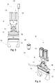
- the first sealing jaw 11 and the second sealing jaw 12 are moveable between an open position in which the sealing jaws 11 and 12 are spaced from each other, as shown in Figs. 3 and 4 , and a closed position in which the sealing jaws 11, 12 are moved toward each other to engage opposite sides of the wrapping material 3, as shown in Figs. 5 and 6 .
- At least one or both of the sealing jaws 11, 12 may be spring-loaded for movement in the direction normal to the predetermined direction D1.
- the sealing jaws 11, 12 may be moved or driven using any suitable actuation mechanism. For example, as shown in Figs.
- the sealing and cutting device 6 may include at least one pneumatic cylinder 13 that drives the first sealing jaw 11 upwardly and downwardly, such that the first sealing jaw has a spring-loaded type of movement.
- the second sealing jaw 12 may be moved similarly to the first sealing jaw 11.
- the sealing jaws 11, 12 When the sealing jaws 11, 12 are moved toward each other to engage the wrapping material 3, the sealing jaws 11, 12 seal the wrapping material 3 by either a heat sealing process or a cold sealing process.
- the first sealing jaw 11 includes an electrical wire assembly 14 that, via a connector 15, is connected between packaging machine 1 and a housing 16 of the first sealing jaw 11.
- the housing 16 includes a heat element for the first sealing jaw 11 and other heating components such as an insulator for retaining the heat and a temperature sensor to maintain a certain temperature of the first sealing jaw 11 during operation of the packaging machine 1.
- the temperature may be dependent on the material of the wrapping material 3 and in an exemplary embodiment in which the sealing jaws 11, 12 are heated for heat sealing the wrapping material 3, the temperature may be between 110 and 130 degrees Celsius.
- the second sealing jaw 12 may have features that are similar to those of the first sealing jaw 11 for both movement and heating of the second sealing jaw 12. Additionally, the first sealing jaw 11 includes a cutting tool 17 that is arranged in the first sealing jaw 11 and is actuated to cut the wrapping material 3 when the sealing jaws 11 have been moved towards each other to fixedly engage and seal the wrapping material 3. Any suitable cutting tool 17 may be used, such as a knife or blade, and the cutting tool 17 may extend along the width w of the first sealing jaw 11 which is equivalent to the width of the conveyor line 5, as shown in Fig. 5 . The cutting tool 17 is operated to move downwardly through the first sealing jaw 11 to cut the wrapping material 3 after the wrapping material 3 is sealed by engagement of the sealing jaws 11, 12.
- the sealing jaws 11, 12 have end surfaces 18, 19 that are advantageously angled or curved relative to the predetermined direction D1.
- the end surfaces 18, 19 may have a curved or straight concave shape, or a curved or straight convex shape.
- the end surfaces 18, 19 extend along the width w of the conveyor line 5 and in a direction perpendicular to the predetermined direction D1 in which the wrapping material 3 travels through the sealing jaws 11, 12.
- the end surface 18 of the first sealing jaw 11 is a bottom surface or the lowest surface of the first sealing jaw 11 nearest to the second sealing jaw 12.
- the end surface 19 of the second sealing jaw 12 is a top surface or the upper most surface of the second sealing jaw 12 nearest to the first sealing jaw 11.
- the end surfaces 18, 19 each have a shape or curvature that is complementary to the other end surface such that the end surfaces 18, 19 tightly fit together over opposing sides of the wrapping material 3.
- the end surfaces 18, 19 may be curved or arc-shaped.
- the first end surface 18 of the first sealing jaw 11 may have a downward curved concave shape and the second end surface 19 of the second sealing jaw 12 may have an upward curved convex shape such that the concave shape is received in the convex shape.
- the first end surface may have a downward convex shape and the second end surface may have an upward concave shape.
- the end surface 18 is formed of two adjacent surface portions 20, 21.
- a slot 22 is defined between the adjacent surface portions 20, 21 which mirror each other on opposite sides of the slot 22.
- the cutting tool 17 shown in Figs.
- the adjacent surface portions 20, 21 both have the same radius of curvature R 1 , and outer ends 23, 24, and inner ends 25, 26 that are adjacent the slot 22.
- the outer ends 23, 24 are lower than the inner ends 25, 26, i.e. are located closer to the second sealing jaw 12.
- the horizontal distance between the outer ends 23, 24 may be between 20 and 22 millimeters and the horizontal distance between the inner ends 25, 26 may be between 5.1 and 5.3 millimeters.
- the distance between the inner ends 25, 26 may also define the length of the slot 22.
- the vertical distance between the inner ends 25, 26 and the outer ends 23, 24 may be between 1.25 and 1.27 millimeters.
- the vertical distance may be equivalent to a vertical distance that the wrapping material is stretched relative to the predetermined direction D1 when the sealing jaws 11, 12 engage the wrapping material. In other embodiments, the vertical distance and stretching of the wrapping material may be greater.
- the radius of curvature R 1 of the adjacent surface portions 20, 21 may be between 44 and 46 millimeters and the central angle ⁇ 1 between the outer ends 23, 24 may be between 25 and 30 degrees.
- the dimensions described herein are merely exemplary and the sealing jaws may be sized up or down depending on the application.
- each of the two adjacent surface portions 20, 21 may further include a plurality of waves or ridges 27 that extend along the width of each adjacent surface portion 20, 21 and are arranged along the corresponding curved adjacent surface portion 20, 21.
- the ridges 27 may be arranged along the entire area of the two adjacent surface portions 20, 21 and formed of both concave and convex curvatures.
- the ridges 27 are symmetrical in shape and both the concave and convex curvatures have a radius of curvature R 2 in the predetermined direction D 1 .
- the radius of curvature R 2 of each ridge 27 may be between 0.4 and 0.6 millimeters.
- Each adjacent surface portion 20, 21 may have any suitable number of ridges, such as between three and five ridges.
- the ridges 27 may be used to provide additional features of the cut edges of the wrapped ice cream products, such as wavy edges.
- the end surface 19 of the second sealing jaw 12 is formed of two adjacent portions 28, 29.
- a slot 30 is defined between the adjacent portions 28, 29 which mirror each other on opposite sides of the slot 30.
- the slot 30 receives the cutting tool 17 during operation.
- the adjacent surface portions 28, 29 both have the same radius of curvature R 3 , which may correspond to the curvature R 1 shown in Fig. 8 , and outer ends 31, 32, and inner ends 33, 34 that are adjacent the slot 30.
- the outer ends 31, 32 are lower than the inner ends 33, 34, i.e. are located closer to the first sealing jaw 11.
- the horizontal distance between the outer ends 31, 32 may be between 24 and 26 millimeters, which is greater than the distance between the outer ends 23, 24 of the first sealing jaw 11.
- the horizontal distance between the inner ends 33, 34 may be between 4.1 and 4.3 millimeters, which may also be the length of the slot 30.
- the vertical distance between the inner ends 33, 34 and the outer ends 31, 32 may be between 2.38 and 2.40 millimeters.
- the radius of curvature R 3 of the adjacent surface portions 28, 29 may be between 33 and 35 millimeters and the central angle ⁇ 2 between the outer ends 31, 32 may be between 40 and 45 degrees.
- the central angle ⁇ 2 may be greater than the central angle ⁇ 1 of the outer ends 23, 24 of the first sealing jaw 11 such that the adjacent surface portions 20, 21 of the first sealing jaw 11 are complementary in shape with less than an entire surface area of the adjacent surface portions 28, 29 of the second sealing jaw 12.
- the adjacent surface portions 20, 21 of the first sealing jaw 11 may be complementary in shape with the entire surface area of the adjacent surface portions 28, 29 of the second sealing jaw 12 such that the central angles ⁇ 1 , ⁇ 2 would be approximately the same.
- the dimensions described herein are merely exemplary and the sealing jaws may be sized up or down depending on the application.
- each of the two adjacent surface portions 28, 29 may further include a plurality of waves or ridges 35 that extend along the width of each adjacent surface portion 28, 29 and are arranged along the corresponding curved adjacent surface portion 28, 29.
- the ridges 35 may be symmetrical in shape and have convex and concave curvatures that each have a radius of curvature R 4 in the predetermined direction D 1 .
- the radius of curvature R 4 may be between 0.4 and 0.6 millimeters.
- the radius of curvature R 4 corresponds to the radius of curvature R 2 of the ridges 27 of the first sealing jaw 11 such that the ridges 35 and ridged surface are complementary in shape relative to the ridges 27 of the first sealing jaw 11.
- Each adjacent surface portion 28, 29 may have any suitable number of ridges, such as between three and five ridges.
- the ridges 35 may not be arranged along the entire area of the adjacent surface portions 28, 29.
- the adjacent surface portions 28, 29 may have an area 36 that is not ridged and does not engage the wrapping material 3.
- Fig. 12 schematically shows another embodiment of the first sealing jaw 111 and the second sealing jaw 112 in which the end surfaces 118, 119 have adjacent surface portions 37, 38, 39, 40 that are similar to the aforementioned adjacent surface portions, but without ridges.
- the first end surface 118 has a downward concave curvature and the second end surface 119 has an upward convex curvature that is complementary in shape relative to the first end surface 118 such that the convex curvature is at least partially received in the concave curvature of the first sealing jaw 111.
- the first end surface may have a downward convex curvature and the second end surface may have an upward concave curvature that receives the downward convex curvature.
- the adjacent surface portions 37, 38 of the first sealing jaw 211 mirror each other opposite the slot 41 and the adjacent surface portions 39, 40 of the second sealing jaw 212 mirror each other opposite the slot 42.
- the adjacent surface portion 37 is complementary in shape to the adjacent surface portion 39 and the adjacent surface portion 38 is complementary in shape to the adjacent surface portion 40.
- the end surfaces 118, 119 are complementary in shape relative to each other over the entire length L 1 , L 2 of the end surfaces 118, 119.
- the height h 1 and outer length L 1 of the end surface 118 may be equal to the height h 2 and the outer length L 2 of the end surface 119.
- the inner lengths L 3 , L 4 and the radii of curvature R 5 and R 6 of the end surfaces 118, 119, respectively, may also be equivalent to each other.
- the end surfaces 118, 119 move toward each other to engage, stretch the material over the end surfaces, and seal the wrapping material along the conveyor line moving in the predetermined direction D1.
- the heights h 1 , h 2 may be equivalent to a distance that the wrapping material is vertically stretched in a direction normal to the predetermined direction D1 during the engagement of sealing jaws 111, 112.
- the stretching may correspond to a distance of between 1.0 and 1.5 millimeters. In other embodiments, the distance may be greater.
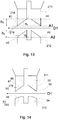
- Fig. 13 schematically shows another embodiment of the first sealing jaw 211 and the second sealing jaw 212 in which the sealing jaws 211, 212 have end surfaces 218, 219 that are similar to the above described end surfaces, but are angled relative to the predetermined direction D1.
- the end surface 218 may have a straight concave shape and the end surface 219 may have a straight convex shape such that the convex shape of the second sealing jaw 212 is at least partially received in the concave shape of the first sealing jaw 211.
- the end surfaces 218, 219 may be complementary in shape to each other and the end surfaces 219, 219 may or may or may not include ridges as described above.
- the height h 3 of the end surface 218 may be equal to the height h 4 of the end surface 219.
- the inner and outer lengths in the direction D1 of the end surfaces may also be equivalent. In other embodiments, the lengths of the corresponding surfaces may be different such that only a portion of the surfaces are complementary in shape.
- the first end surface 218 of the first sealing jaw 211 may be angled relative to the horizontal axis A1 of the outer ends 43, 44 by an angle ⁇ 3 and the second end surface 219 of the second sealing jaw 212 may be angled relative to the horizontal axis A2 of the outer ends 45, 46 by an angle ⁇ 4 .
- the horizontal axes A1, A2 of the outer ends 43, 44, 45, 46 are parallel with the conveyor line traveling in the predetermined direction D1.
- the angles ⁇ 3 , ⁇ 4 may be equal or nearly equal to each other and the angles may be between 15 and 25 degrees. Other angles may also be suitable.
- the amount of stretching of the wrapping material that occurs by engagement of the wrapping material between the sealing jaws 211, 212 will be proportional to the angle of the angled surfaces. For example, the wrapping material will be stretched more relative to the conveyor line when the angle is increased.
- Fig. 14 schematically shows another embodiment of the first sealing jaw 311 and the second sealing jaw 312 in which the first end surface 318 of the first sealing jaw 311 is angled relative to the predetermined direction D1 and the second end surface 319 of the second sealing jaw 312 is curved relative to the predetermined direction D1.
- the first end surface 318 may be angled as described above and the second end surface 319 may be curved as described above.
- the end surfaces 318, 319 may or may not have ridges and may engage the wrapping material along a portion of each end surface 318, 319.
- a surface area of the linear adjacent surface portion 47 of the angled first end surface 318 and a corresponding arc length of the curved adjacent surface portion 48 of the second end surface 319 may move toward each other to engage the wrapping material 3 therebetween.
- the first sealing jaw 311 is angled downwardly from the inner ends 49, 50 to the outer ends 51, 52 and the second sealing jaw 312 is curved convexly upwardly from the outer ends 53, 54.
- the second sealing jaw may be angled upwardly from the inner ends to the outer ends.
- the first sealing jaw may be curved and the second sealing jaw may be angled.
- any combination of angled or curved surfaces that enable stretching of the wrapping material may be suitable for the sealing jaws.
- the surfaces 318, 319 of the jaws 311, 312 are complementary in shape, since one of surfaces receives the other due to their concave respectively convex shape.
- a method 60 of producing wrapped ice cream products 7 (as shown in Fig. 2 ) using the packaging machine 1 that receives the wrapping material 3 and the ice cream product 4 is schematically shown.
- the method 60 includes a step 61 of receiving the wrapping material 3 using the infeed mechanism 2 to move the wrapping material 3 and the ice cream product 4 in the predetermined direction D1 relative to and between the sealing jaws 11, 12 (as shown in Fig. 2 ).
- the method 60 further includes a step 62 of moving the sealing jaws 11, 12 toward each other to engage the wrapping material 3.
- Step 63 of the method includes stretching the wrapping material 3 by engaging the wrapping material 3 between the angled or curved surfaces of the sealing jaws 11, 12 to stretch the wrapping material 3 over the angled or curved surfaces.
- step 64 of the method 60 includes heat sealing or cold sealing the wrapping material 3 to seal and enclose the ice cream product 4 and step 65 includes cutting the sealed wrapping material 3 using the cutting tool 17 to produce the wrapped ice cream product 7.
- the wrapping material 3 is stretched downwardly, or upwardly in other embodiments, when the wrapping material 3 is engaged between the sealing jaws 11, 12.
- the wrapping material 3 is stretched by a distance S in a direction that is normal of the direction D1, which translates to a stretching or expansion in the length of the wrapping material 3 in the predetermined direction D1.
- the wrapping material Before stretching the wrapping material has the length illustrated by the solid line showing the unstretched wrapping material 3 in Fig. 16 .
- the wrapping material After being stretched due to the angle or curvature of the surfaces of the sealing jaws, the wrapping material has the length illustrated by the dotted line showing the stretched wrapping material 3'. The difference in lengths between the dotted line and solid line represents the stretching of the wrapping material.
- the wrapping material 3 may be stretched such that the length L S of the stretched wrapping material 3' is stretched to at least 101% of the original length of the wrapping material 3. In other exemplary embodiments, the length of the stretched wrapping material 3' may be at least 103% or at least 108% of the original length. In still other embodiments, the length of the stretched wrapping material 3' may be between 105% and 120% of the original length or between 105% and 130% of the original length. The amount of stretching of the wrapping material 3 is dependent on the amount of curvature of the angled or curved surfaces of the sealing jaws 11, 12.
- Stretching the wrapping material 3 is advantageous in that the stretching reduces wrinkles as well as slightly thins the area of the wrapping material 3 that is to be sealed, thereby enabling improved contact between the sealing jaws 11, 12 and the wrapping material 3 as compared with conventional sealing jaws.
- the improved contact enables more energy-efficient operating sealing temperatures and a more straight, homogenous sealing.
- the operating temperature of the sealing jaws may be ten percent lower as compared with the operating temperature of conventional heat sealing applications.
Landscapes
- Engineering & Computer Science (AREA)
- Mechanical Engineering (AREA)
- Physics & Mathematics (AREA)
- Manufacturing & Machinery (AREA)
- Thermal Sciences (AREA)
- Fluid Mechanics (AREA)
- Package Closures (AREA)
Abstract
Description
- The invention relates to a method and system for receiving a wrapping material and an ice cream product to produce wrapped ice cream products, where a pair of sealing jaws are arranged to engage and seal the wrapping material.
- Food products, such as ice cream products, are often automatically packaged using a conveyor-type packaging line. In many solutions, each ice cream product is moved along a conveyor line, or belt, for enclosing the ice cream product inside a wrapping material, sealing the wrapping material, and cutting the wrapping material to produce individually wrapped ice cream products. Multiple products may be placed on the conveyor and arranged in ordered columns and rows to be received for packaging by downstream packaging machines.
- Some current packaging machines use horizontal box-motion wrapping machines. The machines include continuously driven sealing jaws that are moveable toward each other to engage, seal, and cut the wrapping material in between individual ice cream products that are located inside a length of wrapping material. Current sealing jaws successfully accomplish sealing of wrapping materials around ice cream products. However, in some cases the appearance as well as the quality and thus the integrity of the sealed wrapping material differ in an undesirable way.
- It is an object of the invention to at least partly overcome one or more limitations of the prior art. In particular, it is an object to provide sealing jaws that are configured to produce a more consistent final seal and cut of the wrapping material enclosing the ice cream products.
- According to an aspect of the invention, a packaging machine is configured to receive a wrapping material and an ice cream product to produce wrapped ice cream products, and includes a first sealing jaw, a second sealing jaw, and an infeed mechanism arranged to move the wrapping material and the ice cream product in a predetermined direction relative to and between the sealing jaws. The sealing jaws are moveable towards each other to engage and seal the wrapping material to enclose an ice cream product inside the wrapping material. The first sealing jaw has a surface that is angled or curved relative to the predetermined direction and the second sealing jaw has a surface that is angled or curved relative to the predetermined direction and complementary in shape to the angled or curved surface of the first sealing jaw, such that the sealing jaws stretch the wrapping material over the angled or curved surfaces when the sealing jaws are moved toward each other to engage and seal the wrapping material.
- The sealing jaws described herein are advantageous in that the jaws are curved or angled relative to the direction of travel of the wrapping material and the ice cream products. The curved or angled surfaces of the sealing jaws are complementary in shape to each other such that the sealing jaws stretch the wrapping material when the sealing jaws are moved toward each other to engage the wrapping material. The stretched material enables improved contact between the sealing jaws and the wrapping material during sealing. In case of heat sealing, more energy-efficient operating sealing temperatures of the packaging machine is enabled.
- The angled surface of the first sealing jaw may have a concave shape and the angled surface of the second sealing jaw has a convex shape.
- The first sealing jaw and the second sealing jaw may engage the wrapping material along an entire width of both the first sealing jaw and the second sealing jaw.
- The first sealing jaw and the second sealing jaw may either be heated for heat-sealing the wrapping material, or may be arranged for cold-sealing the wrapping material.
- The angled or curved surface of the first sealing jaw and the angled or curved surface of the second sealing jaw may each have ridges that are complementary in shape to each other.
- The ridges may extend along an entire width of the first sealing jaw and the second sealing jaw.
- At least one of the first and the second sealing jaws may be moveable by a pneumatic cylinder.
- The packaging machine may include a cutting tool that is arranged in the first sealing jaw and is actuatable to cut the wrapping material when the sealing jaws have been moved towards each other and fix the wrapping material to engage and seal the wrapping material.
- The angled or curved surface of the first sealing jaw may be formed of two surfaces that are arranged at a distance from each other and angled or curved concavely toward the cutting tool.
- The angled or curved surface of the second sealing jaw may be formed of two surfaces that are arranged at a distance from each other to define a slot therebetween for receiving the cutting tool, the two surfaces of the second sealing jaw being angled or curved convexly toward the first sealing jaw.
- The packaging machine may include a housing from which the second sealing jaw protrudes and an electrical wire assembly that is connected between a heat source and the housing.
- The angled or curved surfaces of the sealing jaws are angled or curved such that they may stretch the wrapping material by a distance of at least 1.0 millimeter relative to the predetermined direction, when the sealing jaws are moved toward each other to engage and seal the wrapping material.
- The angled or curved surfaces of the sealing jaws may stretch a length of the wrapping material by an amount that is between 1% and 30% percent.
- According to another aspect of the invention, a method of producing wrapped ice cream products using a packaging machine includes receiving a wrapping material and an ice cream product using an infeed mechanism arranged to move the wrapping material and the ice cream product in a predetermined direction relative to and between sealing jaws, moving the sealing jaws towards each other to engage and seal the wrapping material to enclose the ice cream product inside the wrapping material, and stretching the wrapping material over angled or curved surfaces of the sealing jaws that are angled or curved relative to the predetermined direction. The angled or curved surfaces of the sealing jaws are complementary in shape relative to each other.
- The method of producing wrapped ice cream products may include any features described in connection with the packaging machine, and vice versa, and shares the same advantages.
- Although various aspects of the invention are set out in the accompanying independent claims, other aspects of the invention may include any combination of features from the described embodiments and/or the accompanying dependent claims with the features of the independent claims, and not only the combinations explicitly set out in the accompanying claims.
- Embodiments of the invention will now be described, by way of example, with reference to the accompanying schematic drawings, where:
-
Fig. 1 is a perspective view of a packaging machine for packaging ice cream products according to an embodiment of the present invention. -
Fig. 2 is a side view of the packaging machine shown inFig. 1 . -
Fig. 3 is a perspective view of a sealing and cutting device of the packaging machine shown inFig. 1 according to an embodiment of the present invention when the device is in an open position. -
Fig. 4 is a side view of the device shown inFig. 3 . -
Fig. 5 is a front view of the device shown inFig. 3 . -
Fig. 6 is a perspective view of the device shown inFig. 3 when the wrapping device is in a closed position to engage a wrapping material. -
Fig. 7 is a side view of the device shown inFig. 6 . -
Fig. 8 is a detailed side view of a first sealing jaw of the device shown inFig. 3 . -
Fig. 9 is a detailed side view of the ridges of the first sealing jaw shown inFig. 8 . -
Fig. 10 is a detailed side view of a second sealing jaw of the wrapping device shown inFig. 3 . -
Fig. 11 is a detailed side view of the ridges of the second sealing jaw shown inFig. 10 . -
Fig. 12 is a side view of a sealing and cutting device according to another embodiment of the present invention. -
Fig. 13 is a side view of a sealing and cutting device according to another embodiment of the present invention. -
Fig. 14 is a side view of a sealing and cutting device according to another embodiment of the present invention. -
Fig. 15 is a flow chart of a method of producing wrapped ice cream products using a packaging machine. -
Fig. 16 is a schematic view showing a stretching of the wrapping material. - The method and system according to the present invention has particular application in a packaging machine for producing wrapped ice cream products, such as ice cream bars having a stick, ice cream having a cone or ice cream sandwiches. Packaging machines for other frozen ice cream products, such as stick novelties, bar products, cakes, or candy bars may also be suitable applications. The method and system use sealing jaws having curved or angled surfaces that are moveable toward each other to engage and stretch the wrapping material over the curved or angled surfaces, and seal the stretched portion of the wrapping material to enclose the ice cream product. Stretching the wrapping material enables better contact between the sealing jaws and the wrapping material which enables the packaging machine to operate at more energy-efficient sealing temperatures, such as lower heating temperatures when heat-sealing the wrapping material. Additionally, using the angled or curved sealing jaws provides wrapped ice cream products that have wrapping material with curved or angled cut edges, in contrast to the wrapped products having wrapping material with straight cut edges as produced by conventional packaging machines and processes.
- Referring first to
Figs. 1 and2 , anexemplary packaging machine 1 for producing wrapped ice cream products is shown. Thepackaging machine 1 includes aninfeed mechanism 2 that feeds a wrappingmaterial 3 and anice cream product 4 in a predetermined direction D1 relative to thepackaging machine 1 for sealing and wrapping. The wrappingmaterial 3 may be any suitable material, such as a plastic material or foil material, and layers of wrappingmaterial 3 are arranged under and over eachice cream product 4 as a single elongated sheet that forms a tube in which theice cream product 4 is located. The feeding of the wrappingmaterial 3 and forming it into a tube in which theice cream product 4 is located is accomplished by using conventional techniques and principles. The infeedmechanism 2 includes aconveyor line 5 and operates in a known manner. The wrappingmaterial 3 andice cream product 4 are moved in the predetermined direction D1 through a sealing and cuttingdevice 6 of thepackaging machine 1 such that eachice cream product 4 is sealed and enclosed in thewrapping material 3 to form an individual, wrappedice cream product 7, as shown inFig. 2 . The sealing and cuttingdevice 6 is configured for box-motion such that the sealing and cuttingdevice 6 moves continuously between eachice cream product 4 to seal and cut the wrappingmaterial 3. As best shown inFig. 1 , theconveyor line 5 of theinfeed mechanism 2 may have a plurality oflanes 8 arranged along a width w of theconveyor line 5 and eachlane 8 may contain a plurality of ice cream products. The width w of theconveyor line 5 is perpendicular to the predetermined direction D1. - Referring in addition to
Figs. 3-7 , the sealing and cuttingdevice 6 of thepackaging machine 1 is shown. The sealing and cuttingdevice 6 is arranged along the width w of theconveyor line 5 and in a direction normal to the predetermined direction D1 in which thewrapping material 3 and theice cream product 4 moves. The sealing and cuttingdevice 6 includes a topmoveable portion 9 that is arranged above theconveyor line 5 and a bottommoveable portion 10 that is arranged below theconveyor line 5, as schematically shown inFig. 4 . The topmoveable portion 9 and the bottommoveable portion 10 are vertically aligned with each other. The topmoveable portion 9 has afirst sealing jaw 11 at a bottom end thereof and the bottommoveable portion 10 has asecond sealing jaw 12 at a top end thereof. The sealingjaws moveable portions jaws - The
first sealing jaw 11 and thesecond sealing jaw 12 are moveable toward each other, in a direction perpendicular to the predetermined direction D1, to engage and seal thewrapping material 3 as the wrappingmaterial 3 moves in the predetermined direction D1 between the sealingjaws jaws jaws material 3 fixes and stretches the wrappingmaterial 3 over the angled or curved surfaces during sealing to produce an angled or curved cut edge of the wrappingmaterial 3. The wrappingmaterial 3 may, along its length in the direction D1 where it is in contact with the sealing jaws, be stretched slightly, such as, for example, by an amount of at least one percent of the original length of the wrappingmaterial 3. In an exemplary embodiment, the wrappingmaterial 3 may be stretched by an amount of at least three percent or at least eight percent. In still another exemplary embodiment, the wrappingmaterial 3 may be stretched by an amount between five and twenty percent, or between five and thirty percent. Stretching the wrappingmaterial 3 thins the area of the wrappingmaterial 3 that is engaged by the sealingjaws jaws material 3. - The
first sealing jaw 11 and thesecond sealing jaw 12 are moveable between an open position in which the sealingjaws Figs. 3 and 4 , and a closed position in which the sealingjaws material 3, as shown inFigs. 5 and 6 . At least one or both of the sealingjaws jaws Figs. 3-7 , the sealing and cuttingdevice 6 may include at least onepneumatic cylinder 13 that drives the first sealingjaw 11 upwardly and downwardly, such that the first sealing jaw has a spring-loaded type of movement. Thesecond sealing jaw 12 may be moved similarly to the first sealingjaw 11. - When the sealing
jaws wrapping material 3, the sealingjaws wrapping material 3 by either a heat sealing process or a cold sealing process. As shown inFigs. 3-7 , in an exemplary embodiment in which the sealingjaws jaw 11 includes anelectrical wire assembly 14 that, via aconnector 15, is connected betweenpackaging machine 1 and ahousing 16 of the first sealingjaw 11. Thehousing 16 includes a heat element for the first sealingjaw 11 and other heating components such as an insulator for retaining the heat and a temperature sensor to maintain a certain temperature of the first sealingjaw 11 during operation of thepackaging machine 1. The temperature may be dependent on the material of the wrappingmaterial 3 and in an exemplary embodiment in which the sealingjaws material 3, the temperature may be between 110 and 130 degrees Celsius. - The
second sealing jaw 12 may have features that are similar to those of the first sealingjaw 11 for both movement and heating of thesecond sealing jaw 12. Additionally, the first sealingjaw 11 includes acutting tool 17 that is arranged in the first sealingjaw 11 and is actuated to cut the wrappingmaterial 3 when the sealingjaws 11 have been moved towards each other to fixedly engage and seal thewrapping material 3. Anysuitable cutting tool 17 may be used, such as a knife or blade, and thecutting tool 17 may extend along the width w of the first sealingjaw 11 which is equivalent to the width of theconveyor line 5, as shown inFig. 5 . The cuttingtool 17 is operated to move downwardly through the first sealingjaw 11 to cut the wrappingmaterial 3 after thewrapping material 3 is sealed by engagement of the sealingjaws - With further reference to
Figs. 8-13 , the sealingjaws end surfaces conveyor line 5 and in a direction perpendicular to the predetermined direction D1 in which thewrapping material 3 travels through the sealingjaws end surface 18 of the first sealingjaw 11 is a bottom surface or the lowest surface of the first sealingjaw 11 nearest to thesecond sealing jaw 12. Theend surface 19 of thesecond sealing jaw 12 is a top surface or the upper most surface of thesecond sealing jaw 12 nearest to the first sealingjaw 11. The end surfaces 18, 19 each have a shape or curvature that is complementary to the other end surface such that the end surfaces 18, 19 tightly fit together over opposing sides of the wrappingmaterial 3. - As shown in
Figs. 8-10 , in an exemplary embodiment of the sealingjaws first end surface 18 of the first sealingjaw 11 may have a downward curved concave shape and thesecond end surface 19 of thesecond sealing jaw 12 may have an upward curved convex shape such that the concave shape is received in the convex shape. In alternative embodiments, the first end surface may have a downward convex shape and the second end surface may have an upward concave shape. As shown inFigs. 8 and 9 , theend surface 18 is formed of twoadjacent surface portions slot 22 is defined between theadjacent surface portions slot 22. The cutting tool 17 (shown inFigs. 3-7 ) may extend through theslot 22 to engage thewrapping material 3 such that theadjacent surface portions tool 17. Theadjacent surface portions slot 22. The outer ends 23, 24 are lower than the inner ends 25, 26, i.e. are located closer to thesecond sealing jaw 12. - In an exemplary embodiment, the horizontal distance between the outer ends 23, 24 may be between 20 and 22 millimeters and the horizontal distance between the inner ends 25, 26 may be between 5.1 and 5.3 millimeters. The distance between the inner ends 25, 26 may also define the length of the
slot 22. The vertical distance between the inner ends 25, 26 and the outer ends 23, 24 may be between 1.25 and 1.27 millimeters. The vertical distance may be equivalent to a vertical distance that the wrapping material is stretched relative to the predetermined direction D1 when the sealingjaws adjacent surface portions - As best shown in
Fig. 9 , each of the twoadjacent surface portions ridges 27 that extend along the width of eachadjacent surface portion adjacent surface portion ridges 27 may be arranged along the entire area of the twoadjacent surface portions ridges 27 are symmetrical in shape and both the concave and convex curvatures have a radius of curvature R2 in the predetermined direction D1. In an exemplary embodiment, the radius of curvature R2 of eachridge 27 may be between 0.4 and 0.6 millimeters. Eachadjacent surface portion ridges 27 may be used to provide additional features of the cut edges of the wrapped ice cream products, such as wavy edges. - As shown in
Figs. 10 and 11 , theend surface 19 of thesecond sealing jaw 12 is formed of twoadjacent portions slot 30 is defined between theadjacent portions slot 30. Theslot 30 receives thecutting tool 17 during operation. Theadjacent surface portions Fig. 8 , and outer ends 31, 32, and inner ends 33, 34 that are adjacent theslot 30. The outer ends 31, 32 are lower than the inner ends 33, 34, i.e. are located closer to the first sealingjaw 11. In an exemplary embodiment, the horizontal distance between the outer ends 31, 32 may be between 24 and 26 millimeters, which is greater than the distance between the outer ends 23, 24 of the first sealingjaw 11. The horizontal distance between the inner ends 33, 34 may be between 4.1 and 4.3 millimeters, which may also be the length of theslot 30. The vertical distance between the inner ends 33, 34 and the outer ends 31, 32 may be between 2.38 and 2.40 millimeters. The radius of curvature R3 of theadjacent surface portions jaw 11 such that theadjacent surface portions jaw 11 are complementary in shape with less than an entire surface area of theadjacent surface portions second sealing jaw 12. In other exemplary embodiments, theadjacent surface portions jaw 11 may be complementary in shape with the entire surface area of theadjacent surface portions second sealing jaw 12 such that the central angles θ1, θ2 would be approximately the same. The dimensions described herein are merely exemplary and the sealing jaws may be sized up or down depending on the application. - As best shown in
Fig. 11 , each of the twoadjacent surface portions ridges 35 that extend along the width of eachadjacent surface portion adjacent surface portion ridges 35 may be symmetrical in shape and have convex and concave curvatures that each have a radius of curvature R4 in the predetermined direction D1. In an exemplary embodiment, the radius of curvature R4 may be between 0.4 and 0.6 millimeters. The radius of curvature R4 corresponds to the radius of curvature R2 of theridges 27 of the first sealingjaw 11 such that theridges 35 and ridged surface are complementary in shape relative to theridges 27 of the first sealingjaw 11. Eachadjacent surface portion jaw 11, theridges 35 may not be arranged along the entire area of theadjacent surface portions Fig. 11 , theadjacent surface portions wrapping material 3. Thus, when the first sealingjaw 11 and thesecond sealing jaw 12 engage thewrapping material 3, the wrappingmaterial 3 is stretched over the ridged surfaces of the sealingjaws -
Fig. 12 schematically shows another embodiment of thefirst sealing jaw 111 and thesecond sealing jaw 112 in which the end surfaces 118, 119 haveadjacent surface portions second end surface 119 has an upward convex curvature that is complementary in shape relative to the first end surface 118 such that the convex curvature is at least partially received in the concave curvature of thefirst sealing jaw 111. In an alternative embodiment, the first end surface may have a downward convex curvature and the second end surface may have an upward concave curvature that receives the downward convex curvature. Theadjacent surface portions first sealing jaw 211 mirror each other opposite theslot 41 and theadjacent surface portions second sealing jaw 212 mirror each other opposite theslot 42. Theadjacent surface portion 37 is complementary in shape to theadjacent surface portion 39 and theadjacent surface portion 38 is complementary in shape to theadjacent surface portion 40. - The end surfaces 118, 119 are complementary in shape relative to each other over the entire length L1, L2 of the end surfaces 118, 119. The height h1 and outer length L1 of the end surface 118 may be equal to the height h2 and the outer length L2 of the
end surface 119. The inner lengths L3, L4 and the radii of curvature R5 and R6 of the end surfaces 118, 119, respectively, may also be equivalent to each other. In operation, the end surfaces 118, 119 move toward each other to engage, stretch the material over the end surfaces, and seal the wrapping material along the conveyor line moving in the predetermined direction D1. The heights h1, h2, may be equivalent to a distance that the wrapping material is vertically stretched in a direction normal to the predetermined direction D1 during the engagement of sealingjaws -
Fig. 13 schematically shows another embodiment of thefirst sealing jaw 211 and thesecond sealing jaw 212 in which the sealingjaws end surfaces end surface 218 may have a straight concave shape and theend surface 219 may have a straight convex shape such that the convex shape of thesecond sealing jaw 212 is at least partially received in the concave shape of thefirst sealing jaw 211. The end surfaces 218, 219 may be complementary in shape to each other and the end surfaces 219, 219 may or may or may not include ridges as described above. The height h3 of theend surface 218 may be equal to the height h4 of theend surface 219. The inner and outer lengths in the direction D1 of the end surfaces may also be equivalent. In other embodiments, the lengths of the corresponding surfaces may be different such that only a portion of the surfaces are complementary in shape. - The
first end surface 218 of thefirst sealing jaw 211 may be angled relative to the horizontal axis A1 of the outer ends 43, 44 by an angle θ3 and thesecond end surface 219 of thesecond sealing jaw 212 may be angled relative to the horizontal axis A2 of the outer ends 45, 46 by an angle θ4. The horizontal axes A1, A2 of the outer ends 43, 44, 45, 46 are parallel with the conveyor line traveling in the predetermined direction D1. The angles θ3, θ4 may be equal or nearly equal to each other and the angles may be between 15 and 25 degrees. Other angles may also be suitable. The amount of stretching of the wrapping material that occurs by engagement of the wrapping material between the sealingjaws -
Fig. 14 schematically shows another embodiment of thefirst sealing jaw 311 and thesecond sealing jaw 312 in which thefirst end surface 318 of thefirst sealing jaw 311 is angled relative to the predetermined direction D1 and thesecond end surface 319 of thesecond sealing jaw 312 is curved relative to the predetermined direction D1. Thefirst end surface 318 may be angled as described above and thesecond end surface 319 may be curved as described above. The end surfaces 318, 319 may or may not have ridges and may engage the wrapping material along a portion of eachend surface adjacent surface portion 47 of the angledfirst end surface 318 and a corresponding arc length of the curvedadjacent surface portion 48 of thesecond end surface 319 may move toward each other to engage thewrapping material 3 therebetween. As shown inFig. 14 , thefirst sealing jaw 311 is angled downwardly from the inner ends 49, 50 to the outer ends 51, 52 and thesecond sealing jaw 312 is curved convexly upwardly from the outer ends 53, 54. In other embodiments, the second sealing jaw may be angled upwardly from the inner ends to the outer ends. In still other embodiments, the first sealing jaw may be curved and the second sealing jaw may be angled. Thus, any combination of angled or curved surfaces that enable stretching of the wrapping material may be suitable for the sealing jaws. Still, thesurfaces jaws - Referring now to
Figs. 15 and 16 , amethod 60 of producing wrapped ice cream products 7 (as shown inFig. 2 ) using thepackaging machine 1 that receives the wrappingmaterial 3 and theice cream product 4 is schematically shown. Themethod 60 includes astep 61 of receiving the wrappingmaterial 3 using theinfeed mechanism 2 to move thewrapping material 3 and theice cream product 4 in the predetermined direction D1 relative to and between the sealingjaws 11, 12 (as shown inFig. 2 ). Themethod 60 further includes astep 62 of moving the sealingjaws wrapping material 3.Step 63 of the method includes stretching the wrappingmaterial 3 by engaging the wrappingmaterial 3 between the angled or curved surfaces of the sealingjaws material 3 over the angled or curved surfaces. After thewrapping material 3 is engaged, step 64 of themethod 60 includes heat sealing or cold sealing the wrappingmaterial 3 to seal and enclose theice cream product 4 and step 65 includes cutting the sealedwrapping material 3 using thecutting tool 17 to produce the wrappedice cream product 7. - As shown schematically in
Fig. 16 , the wrappingmaterial 3 is stretched downwardly, or upwardly in other embodiments, when the wrappingmaterial 3 is engaged between the sealingjaws material 3 is stretched by a distance S in a direction that is normal of the direction D1, which translates to a stretching or expansion in the length of the wrappingmaterial 3 in the predetermined direction D1. Before stretching the wrapping material has the length illustrated by the solid line showing theunstretched wrapping material 3 inFig. 16 . After being stretched due to the angle or curvature of the surfaces of the sealing jaws, the wrapping material has the length illustrated by the dotted line showing the stretched wrapping material 3'. The difference in lengths between the dotted line and solid line represents the stretching of the wrapping material. - In an exemplary embodiment, the wrapping
material 3 may be stretched such that the length LS of the stretched wrapping material 3' is stretched to at least 101% of the original length of the wrappingmaterial 3. In other exemplary embodiments, the length of the stretched wrapping material 3' may be at least 103% or at least 108% of the original length. In still other embodiments, the length of the stretched wrapping material 3' may be between 105% and 120% of the original length or between 105% and 130% of the original length. The amount of stretching of the wrappingmaterial 3 is dependent on the amount of curvature of the angled or curved surfaces of the sealingjaws material 3 is advantageous in that the stretching reduces wrinkles as well as slightly thins the area of the wrappingmaterial 3 that is to be sealed, thereby enabling improved contact between the sealingjaws material 3 as compared with conventional sealing jaws. The improved contact enables more energy-efficient operating sealing temperatures and a more straight, homogenous sealing. In a heat sealing application, the operating temperature of the sealing jaws may be ten percent lower as compared with the operating temperature of conventional heat sealing applications. - While the invention has been described with reference to one or more preferred embodiments, which embodiments have been set forth in considerable detail for the purposes of making a complete disclosure of the invention, such embodiments are merely exemplary and are not intended to be limiting or represent an exhaustive enumeration of all aspects of the invention. The scope of the invention, therefore, shall be defined solely by the following claims. Further, it will be apparent to those of skill in the art that numerous changes may be made in such details without departing from the spirit and the principles of the invention.
Claims (14)
- A packaging machine (1) configured to receive a wrapping material (3) and an ice cream product (4) to produce wrapped ice cream products (7), the packaging machine(1) comprising a first sealing jaw (11), a second sealing jaw (12) and an infeed mechanism(2) arranged to move the wrapping material (3) and the ice cream product (4) in a predetermined direction (D1) relative to and between the sealing jaws (11, 12), wherein the sealing jaws (11, 12) are moveable towards each other to engage and seal the wrapping material (3) to enclose the ice cream product (4) inside the wrapping material (3),
characterized in thatthe first sealing jaw (11) has a surface (18) that is angled or curved relative to the predetermined direction (D1); andthe second sealing jaw (12) has a surface (19) that is angled or curved relative to the predetermined direction (D1) and complementary in shape to the angled or curved surface (12) of the first sealing jaw (11), such that the sealing jaws (11, 12) stretch the wrapping material (3) over the angled or curved surfaces (18, 19) when the sealing jaws (11, 12) are moved toward each other to engage and seal the wrapping material (3). - The packaging machine (1) according to claim 1, wherein the angled or curved surface (18) of the first sealing jaw (11) has a concave shape and the angled or curved surface (19) of the second sealing jaw (12) has a convex shape.
- The packaging machine (1) according to any preceding claim, wherein the first sealing jaw (11) and the second sealing jaw (11) engage the wrapping material (3) along an entire width (w) of both the first sealing jaw (11) and the second sealing jaw (12).
- The packaging machine (1) according to any preceding claim, wherein the first sealing jaw (11) and the second sealing jaw (12) are one of:heated for heat-sealing the wrapping material (3); orarranged for cold-sealing the wrapping material (3).
- The packaging machine (1) according to any preceding claim, wherein the angled or curved surface (18) of the first sealing jaw (11) and the angled or curved surface (19) of the second sealing jaw (12) each have ridges (27, 35) that are complementary in shape to each other.
- The packaging machine (1) according to claim 5, wherein the ridges (27, 35) extend along an entire width (w) of the first sealing jaw (11) and the second sealing jaw (12).
- The packaging machine (1) according to any preceding claim, wherein at least one of the first and the second sealing jaws (11, 12) is moveable by a pneumatic cylinder (13).
- The packaging machine (1) according to any preceding claim, comprising a cutting tool (17) that is arranged in the first sealing jaw (11) and is actuatable to cut the wrapping material (3) when the sealing jaws (11, 12) have been moved towards each other and fix the wrapping material (3) to engage and seal the wrapping material (3).
- The packaging machine (1) according to claim 8, wherein the angled or curved surface (18) of the first sealing jaw (11) comprises two surfaces (20, 21) that are arranged at a distance from each other and angled or curved concavely toward the cutting tool (17).
- The packaging machine (1) according to claim 9, wherein the angled or curved surface (19) of the second sealing jaw (12) comprises two surfaces (28, 29) that are arranged at a distance from each other to define a slot (30) therebetween for receiving the cutting tool (17), the two surfaces (28, 29) of the second sealing jaw (12) being angled or curved convexly toward the first sealing jaw (11).
- The packaging machine (1) according to any preceding claim, comprising a housing (16) from which the first sealing jaw (11) protrudes, and an electrical wire assembly (14) that is connected between a heat source (15) and the housing (16).
- The packaging machine (1) according to any preceding claim, wherein the angled or curved surfaces (18, 19) of the sealing jaws (11, 12) are angled or curved such that they stretch the wrapping material (3) by a distance (h1) of at least 1.0 millimeter relative to the predetermined direction (D1), when the sealing jaws (11, 12) are moved toward each other to engage and seal the wrapping material (3).
- The packaging machine (1) according to any preceding claim, wherein the angled or curved surfaces (18, 19) of the sealing jaws (11, 12) stretch a length (Ls) of the wrapping material (3) by at least 1%, or by an amount that is between 1% and 30%.
- A method (60) of producing wrapped ice cream products (7) using a packaging machine (1), the method comprising:receiving (61) a wrapping material (3) and an ice cream product (4) using an infeed mechanism (2) arranged to move the wrapping material (3) and the ice cream product (4) in a predetermined direction (D1) relative to and between sealing jaws (11, 12,);moving (62) the sealing jaws (11, 12) towards each other to engage and seal the wrapping material (3) to enclose the ice cream product (4) inside the wrapping material (3); andstretching (63) the wrapping material (3) over angled or curved surfaces (18, 19) of the sealing jaws (11, 12) that are angled or curved relative to the predetermined direction (D1), the angled or curved surfaces (18, 19) of the sealing jaws (11, 12) being complementary in shape relative to each other.
Applications Claiming Priority (1)
| Application Number | Priority Date | Filing Date | Title |
|---|---|---|---|
| EP18198393 | 2018-10-03 |
Publications (2)
| Publication Number | Publication Date |
|---|---|
| EP3632660A1 true EP3632660A1 (en) | 2020-04-08 |
| EP3632660B1 EP3632660B1 (en) | 2021-11-17 |
Family
ID=63762253
Family Applications (1)
| Application Number | Title | Priority Date | Filing Date |
|---|---|---|---|
| EP19199425.0A Active EP3632660B1 (en) | 2018-10-03 | 2019-09-25 | Angled or curved jaws and method for wrapping ice cream |
Country Status (2)
| Country | Link |
|---|---|
| EP (1) | EP3632660B1 (en) |
| DK (1) | DK3632660T3 (en) |
Cited By (1)
| Publication number | Priority date | Publication date | Assignee | Title |
|---|---|---|---|---|
| DE102022116844A1 (en) | 2022-07-06 | 2023-07-20 | Syntegon Packaging Systems Ag | Sealing device, in particular transverse seam sealing device, packaging machine with such a sealing device and method for sealing a package or a packaging material by means of such a sealing device |
Citations (9)
| Publication number | Priority date | Publication date | Assignee | Title |
|---|---|---|---|---|
| US2966021A (en) * | 1955-12-20 | 1960-12-27 | Liqua Pak Inc | Apparatus for forming, filling, sealing and severing containers |
| JPH0885505A (en) * | 1994-09-20 | 1996-04-02 | Tokyo Autom Mach Works Ltd | Bag-making/filling/packaging device and packaging bag |
| US20020152719A1 (en) * | 2001-04-18 | 2002-10-24 | Kraft Foods Holdings, Inc. | Apparatus for manufacturing flexible packages having slide closures |
| DE102005034284A1 (en) * | 2005-07-22 | 2007-01-25 | Rovema Verpackungsmaschinen Gmbh | Bonding device for thermoplastics, especially foil strips, has a sealing surface on a jaw unit and a heating device to heat up the sealing surface |
| JP2009149365A (en) * | 2007-12-24 | 2009-07-09 | Nihon Tetra Pak Kk | SEALING DEVICE, PACKAGING FILLING DEVICE, AND SEALING METHOD |
| EP2311735A1 (en) * | 2008-06-17 | 2011-04-20 | Ishida Co., Ltd. | Bag-making packaging machine |
| WO2014079457A2 (en) * | 2012-11-20 | 2014-05-30 | Gram Equipment A/S | Sealing and cutting unit for a form fill seal machine |
| US9452853B2 (en) * | 2010-07-09 | 2016-09-27 | Kraft Foods Group Brands Llc | Apparatus for forming packages using non-linear sealing jaws |
| US20170152064A1 (en) * | 2015-11-30 | 2017-06-01 | William G. Aurand | Sealing System and Method For Gusseted And Zippered Bags |
-
2019
- 2019-09-25 EP EP19199425.0A patent/EP3632660B1/en active Active
- 2019-09-25 DK DK19199425.0T patent/DK3632660T3/en active
Patent Citations (9)
| Publication number | Priority date | Publication date | Assignee | Title |
|---|---|---|---|---|
| US2966021A (en) * | 1955-12-20 | 1960-12-27 | Liqua Pak Inc | Apparatus for forming, filling, sealing and severing containers |
| JPH0885505A (en) * | 1994-09-20 | 1996-04-02 | Tokyo Autom Mach Works Ltd | Bag-making/filling/packaging device and packaging bag |
| US20020152719A1 (en) * | 2001-04-18 | 2002-10-24 | Kraft Foods Holdings, Inc. | Apparatus for manufacturing flexible packages having slide closures |
| DE102005034284A1 (en) * | 2005-07-22 | 2007-01-25 | Rovema Verpackungsmaschinen Gmbh | Bonding device for thermoplastics, especially foil strips, has a sealing surface on a jaw unit and a heating device to heat up the sealing surface |
| JP2009149365A (en) * | 2007-12-24 | 2009-07-09 | Nihon Tetra Pak Kk | SEALING DEVICE, PACKAGING FILLING DEVICE, AND SEALING METHOD |
| EP2311735A1 (en) * | 2008-06-17 | 2011-04-20 | Ishida Co., Ltd. | Bag-making packaging machine |
| US9452853B2 (en) * | 2010-07-09 | 2016-09-27 | Kraft Foods Group Brands Llc | Apparatus for forming packages using non-linear sealing jaws |
| WO2014079457A2 (en) * | 2012-11-20 | 2014-05-30 | Gram Equipment A/S | Sealing and cutting unit for a form fill seal machine |
| US20170152064A1 (en) * | 2015-11-30 | 2017-06-01 | William G. Aurand | Sealing System and Method For Gusseted And Zippered Bags |
Cited By (1)
| Publication number | Priority date | Publication date | Assignee | Title |
|---|---|---|---|---|
| DE102022116844A1 (en) | 2022-07-06 | 2023-07-20 | Syntegon Packaging Systems Ag | Sealing device, in particular transverse seam sealing device, packaging machine with such a sealing device and method for sealing a package or a packaging material by means of such a sealing device |
Also Published As
| Publication number | Publication date |
|---|---|
| DK3632660T3 (en) | 2022-01-24 |
| EP3632660B1 (en) | 2021-11-17 |
Similar Documents
| Publication | Publication Date | Title |
|---|---|---|
| US5131213A (en) | Sealing jaws | |
| EP2303549B1 (en) | Sealing jaw for producing sealed packages of a food product | |
| US4907394A (en) | Method for producing a foil-container, apparatus for the implementation of the said method, and a foil-container produced according to the said method | |
| JP4162765B2 (en) | High-speed folding unit for machines that package liquid food products | |
| TW379187B (en) | packaging unit for continuously producing sealed packages, containing pourable food products, from a tube of packaging material | |
| EP2586716B1 (en) | Folding unit for pourable food product packaging machines | |
| US4015021A (en) | Method for producing individually wrapped foodstuff slices | |
| JPH0649492B2 (en) | Sealing method for packaging material and its equipment | |
| CZ282954B6 (en) | Process for producing individually packed slices of a foodstuff article, and apparatus for making the same | |
| MX2014008989A (en) | Folding unit for pourable food product packaging machines. | |
| CN103213314A (en) | Bag making machine | |
| EP3632660B1 (en) | Angled or curved jaws and method for wrapping ice cream | |
| US6860958B2 (en) | Wrinkle reduction assembly | |
| US4302415A (en) | Method of forming foam articles from a foam thermoplastic web | |
| US7051633B2 (en) | Ampoule card splitter | |
| EP2603434B1 (en) | Packaging apparatus including rotary jaw device and method of making packages | |
| US5293795A (en) | Method and apparatus for cutting and shaping belt-like members | |
| CA1311698C (en) | Method for producing a foil-container, apparatus for the implementation of the said method, and a foil-container produced according to the said method | |
| EP1341695B1 (en) | A process and device for tilting a continuous strip of containers made from heat-formable material | |
| EP1323348B1 (en) | Process and machine for packing pasty, liquid or semiliquid products | |
| US5537804A (en) | Film sealing apparatus and method | |
| JPS6330204B2 (en) | ||
| JP6663707B2 (en) | Film cutting device and film cutting method | |
| JP6249554B2 (en) | Vertical bag making and filling machine | |
| US7955467B2 (en) | Method and device for producing a groove near an intended edge part of a conveyor belt, which groove is intended to be filled with a filler having sealing properties |
Legal Events
| Date | Code | Title | Description |
|---|---|---|---|
| PUAI | Public reference made under article 153(3) epc to a published international application that has entered the european phase |
Free format text: ORIGINAL CODE: 0009012 |
|
| STAA | Information on the status of an ep patent application or granted ep patent |
Free format text: STATUS: THE APPLICATION HAS BEEN PUBLISHED |
|
| AK | Designated contracting states |
Kind code of ref document: A1 Designated state(s): AL AT BE BG CH CY CZ DE DK EE ES FI FR GB GR HR HU IE IS IT LI LT LU LV MC MK MT NL NO PL PT RO RS SE SI SK SM TR |
|
| AX | Request for extension of the european patent |
Extension state: BA ME |
|
| STAA | Information on the status of an ep patent application or granted ep patent |
Free format text: STATUS: REQUEST FOR EXAMINATION WAS MADE |
|
| 17P | Request for examination filed |
Effective date: 20201008 |
|
| RBV | Designated contracting states (corrected) |
Designated state(s): AL AT BE BG CH CY CZ DE DK EE ES FI FR GB GR HR HU IE IS IT LI LT LU LV MC MK MT NL NO PL PT RO RS SE SI SK SM TR |
|
| GRAP | Despatch of communication of intention to grant a patent |
Free format text: ORIGINAL CODE: EPIDOSNIGR1 |
|
| STAA | Information on the status of an ep patent application or granted ep patent |
Free format text: STATUS: GRANT OF PATENT IS INTENDED |
|
| INTG | Intention to grant announced |
Effective date: 20210621 |
|
| GRAS | Grant fee paid |
Free format text: ORIGINAL CODE: EPIDOSNIGR3 |
|
| GRAA | (expected) grant |
Free format text: ORIGINAL CODE: 0009210 |
|
| STAA | Information on the status of an ep patent application or granted ep patent |
Free format text: STATUS: THE PATENT HAS BEEN GRANTED |
|
| AK | Designated contracting states |
Kind code of ref document: B1 Designated state(s): AL AT BE BG CH CY CZ DE DK EE ES FI FR GB GR HR HU IE IS IT LI LT LU LV MC MK MT NL NO PL PT RO RS SE SI SK SM TR |
|
| REG | Reference to a national code |
Ref country code: GB Ref legal event code: FG4D |
|
| REG | Reference to a national code |
Ref country code: DE Ref legal event code: R096 Ref document number: 602019009333 Country of ref document: DE |
|
| REG | Reference to a national code |
Ref country code: IE Ref legal event code: FG4D |
|
| REG | Reference to a national code |
Ref country code: AT Ref legal event code: REF Ref document number: 1447701 Country of ref document: AT Kind code of ref document: T Effective date: 20211215 |
|
| REG | Reference to a national code |
Ref country code: DK Ref legal event code: T3 Effective date: 20220120 |
|
| REG | Reference to a national code |
Ref country code: LT Ref legal event code: MG9D |
|
| REG | Reference to a national code |
Ref country code: NL Ref legal event code: MP Effective date: 20211117 |
|
| REG | Reference to a national code |
Ref country code: AT Ref legal event code: MK05 Ref document number: 1447701 Country of ref document: AT Kind code of ref document: T Effective date: 20211117 |
|
| PG25 | Lapsed in a contracting state [announced via postgrant information from national office to epo] |
Ref country code: RS Free format text: LAPSE BECAUSE OF FAILURE TO SUBMIT A TRANSLATION OF THE DESCRIPTION OR TO PAY THE FEE WITHIN THE PRESCRIBED TIME-LIMIT Effective date: 20211117 Ref country code: LT Free format text: LAPSE BECAUSE OF FAILURE TO SUBMIT A TRANSLATION OF THE DESCRIPTION OR TO PAY THE FEE WITHIN THE PRESCRIBED TIME-LIMIT Effective date: 20211117 Ref country code: FI Free format text: LAPSE BECAUSE OF FAILURE TO SUBMIT A TRANSLATION OF THE DESCRIPTION OR TO PAY THE FEE WITHIN THE PRESCRIBED TIME-LIMIT Effective date: 20211117 Ref country code: BG Free format text: LAPSE BECAUSE OF FAILURE TO SUBMIT A TRANSLATION OF THE DESCRIPTION OR TO PAY THE FEE WITHIN THE PRESCRIBED TIME-LIMIT Effective date: 20220217 Ref country code: AT Free format text: LAPSE BECAUSE OF FAILURE TO SUBMIT A TRANSLATION OF THE DESCRIPTION OR TO PAY THE FEE WITHIN THE PRESCRIBED TIME-LIMIT Effective date: 20211117 |
|
| PG25 | Lapsed in a contracting state [announced via postgrant information from national office to epo] |
Ref country code: IS Free format text: LAPSE BECAUSE OF FAILURE TO SUBMIT A TRANSLATION OF THE DESCRIPTION OR TO PAY THE FEE WITHIN THE PRESCRIBED TIME-LIMIT Effective date: 20220317 Ref country code: SE Free format text: LAPSE BECAUSE OF FAILURE TO SUBMIT A TRANSLATION OF THE DESCRIPTION OR TO PAY THE FEE WITHIN THE PRESCRIBED TIME-LIMIT Effective date: 20211117 Ref country code: PT Free format text: LAPSE BECAUSE OF FAILURE TO SUBMIT A TRANSLATION OF THE DESCRIPTION OR TO PAY THE FEE WITHIN THE PRESCRIBED TIME-LIMIT Effective date: 20220317 Ref country code: PL Free format text: LAPSE BECAUSE OF FAILURE TO SUBMIT A TRANSLATION OF THE DESCRIPTION OR TO PAY THE FEE WITHIN THE PRESCRIBED TIME-LIMIT Effective date: 20211117 Ref country code: NO Free format text: LAPSE BECAUSE OF FAILURE TO SUBMIT A TRANSLATION OF THE DESCRIPTION OR TO PAY THE FEE WITHIN THE PRESCRIBED TIME-LIMIT Effective date: 20220217 Ref country code: NL Free format text: LAPSE BECAUSE OF FAILURE TO SUBMIT A TRANSLATION OF THE DESCRIPTION OR TO PAY THE FEE WITHIN THE PRESCRIBED TIME-LIMIT Effective date: 20211117 Ref country code: LV Free format text: LAPSE BECAUSE OF FAILURE TO SUBMIT A TRANSLATION OF THE DESCRIPTION OR TO PAY THE FEE WITHIN THE PRESCRIBED TIME-LIMIT Effective date: 20211117 Ref country code: HR Free format text: LAPSE BECAUSE OF FAILURE TO SUBMIT A TRANSLATION OF THE DESCRIPTION OR TO PAY THE FEE WITHIN THE PRESCRIBED TIME-LIMIT Effective date: 20211117 Ref country code: GR Free format text: LAPSE BECAUSE OF FAILURE TO SUBMIT A TRANSLATION OF THE DESCRIPTION OR TO PAY THE FEE WITHIN THE PRESCRIBED TIME-LIMIT Effective date: 20220218 Ref country code: ES Free format text: LAPSE BECAUSE OF FAILURE TO SUBMIT A TRANSLATION OF THE DESCRIPTION OR TO PAY THE FEE WITHIN THE PRESCRIBED TIME-LIMIT Effective date: 20211117 |
|
| PG25 | Lapsed in a contracting state [announced via postgrant information from national office to epo] |
Ref country code: SM Free format text: LAPSE BECAUSE OF FAILURE TO SUBMIT A TRANSLATION OF THE DESCRIPTION OR TO PAY THE FEE WITHIN THE PRESCRIBED TIME-LIMIT Effective date: 20211117 Ref country code: SK Free format text: LAPSE BECAUSE OF FAILURE TO SUBMIT A TRANSLATION OF THE DESCRIPTION OR TO PAY THE FEE WITHIN THE PRESCRIBED TIME-LIMIT Effective date: 20211117 Ref country code: RO Free format text: LAPSE BECAUSE OF FAILURE TO SUBMIT A TRANSLATION OF THE DESCRIPTION OR TO PAY THE FEE WITHIN THE PRESCRIBED TIME-LIMIT Effective date: 20211117 Ref country code: EE Free format text: LAPSE BECAUSE OF FAILURE TO SUBMIT A TRANSLATION OF THE DESCRIPTION OR TO PAY THE FEE WITHIN THE PRESCRIBED TIME-LIMIT Effective date: 20211117 Ref country code: CZ Free format text: LAPSE BECAUSE OF FAILURE TO SUBMIT A TRANSLATION OF THE DESCRIPTION OR TO PAY THE FEE WITHIN THE PRESCRIBED TIME-LIMIT Effective date: 20211117 |
|
| REG | Reference to a national code |
Ref country code: DE Ref legal event code: R097 Ref document number: 602019009333 Country of ref document: DE |
|
| PLBE | No opposition filed within time limit |
Free format text: ORIGINAL CODE: 0009261 |
|
| STAA | Information on the status of an ep patent application or granted ep patent |
Free format text: STATUS: NO OPPOSITION FILED WITHIN TIME LIMIT |
|
| 26N | No opposition filed |
Effective date: 20220818 |
|
| PG25 | Lapsed in a contracting state [announced via postgrant information from national office to epo] |
Ref country code: AL Free format text: LAPSE BECAUSE OF FAILURE TO SUBMIT A TRANSLATION OF THE DESCRIPTION OR TO PAY THE FEE WITHIN THE PRESCRIBED TIME-LIMIT Effective date: 20211117 |
|
| PG25 | Lapsed in a contracting state [announced via postgrant information from national office to epo] |
Ref country code: SI Free format text: LAPSE BECAUSE OF FAILURE TO SUBMIT A TRANSLATION OF THE DESCRIPTION OR TO PAY THE FEE WITHIN THE PRESCRIBED TIME-LIMIT Effective date: 20211117 |
|
| PG25 | Lapsed in a contracting state [announced via postgrant information from national office to epo] |
Ref country code: MC Free format text: LAPSE BECAUSE OF FAILURE TO SUBMIT A TRANSLATION OF THE DESCRIPTION OR TO PAY THE FEE WITHIN THE PRESCRIBED TIME-LIMIT Effective date: 20211117 |
|
| REG | Reference to a national code |
Ref country code: CH Ref legal event code: PL |
|
| REG | Reference to a national code |
Ref country code: BE Ref legal event code: MM Effective date: 20220930 |
|
| P01 | Opt-out of the competence of the unified patent court (upc) registered |
Effective date: 20230426 |
|
| PG25 | Lapsed in a contracting state [announced via postgrant information from national office to epo] |
Ref country code: LU Free format text: LAPSE BECAUSE OF NON-PAYMENT OF DUE FEES Effective date: 20220925 |
|
| PG25 | Lapsed in a contracting state [announced via postgrant information from national office to epo] |
Ref country code: LI Free format text: LAPSE BECAUSE OF NON-PAYMENT OF DUE FEES Effective date: 20220930 Ref country code: IE Free format text: LAPSE BECAUSE OF NON-PAYMENT OF DUE FEES Effective date: 20220925 Ref country code: FR Free format text: LAPSE BECAUSE OF NON-PAYMENT OF DUE FEES Effective date: 20220930 Ref country code: CH Free format text: LAPSE BECAUSE OF NON-PAYMENT OF DUE FEES Effective date: 20220930 |
|
| PG25 | Lapsed in a contracting state [announced via postgrant information from national office to epo] |
Ref country code: BE Free format text: LAPSE BECAUSE OF NON-PAYMENT OF DUE FEES Effective date: 20220930 |
|
| PG25 | Lapsed in a contracting state [announced via postgrant information from national office to epo] |
Ref country code: HU Free format text: LAPSE BECAUSE OF FAILURE TO SUBMIT A TRANSLATION OF THE DESCRIPTION OR TO PAY THE FEE WITHIN THE PRESCRIBED TIME-LIMIT; INVALID AB INITIO Effective date: 20190925 |
|
| PG25 | Lapsed in a contracting state [announced via postgrant information from national office to epo] |
Ref country code: CY Free format text: LAPSE BECAUSE OF FAILURE TO SUBMIT A TRANSLATION OF THE DESCRIPTION OR TO PAY THE FEE WITHIN THE PRESCRIBED TIME-LIMIT Effective date: 20211117 |
|
| GBPC | Gb: european patent ceased through non-payment of renewal fee |
Effective date: 20230925 |
|
| PG25 | Lapsed in a contracting state [announced via postgrant information from national office to epo] |
Ref country code: MK Free format text: LAPSE BECAUSE OF FAILURE TO SUBMIT A TRANSLATION OF THE DESCRIPTION OR TO PAY THE FEE WITHIN THE PRESCRIBED TIME-LIMIT Effective date: 20211117 |
|
| PG25 | Lapsed in a contracting state [announced via postgrant information from national office to epo] |
Ref country code: GB Free format text: LAPSE BECAUSE OF NON-PAYMENT OF DUE FEES Effective date: 20230925 |
|
| PG25 | Lapsed in a contracting state [announced via postgrant information from national office to epo] |
Ref country code: GB Free format text: LAPSE BECAUSE OF NON-PAYMENT OF DUE FEES Effective date: 20230925 |
|
| PG25 | Lapsed in a contracting state [announced via postgrant information from national office to epo] |
Ref country code: MT Free format text: LAPSE BECAUSE OF FAILURE TO SUBMIT A TRANSLATION OF THE DESCRIPTION OR TO PAY THE FEE WITHIN THE PRESCRIBED TIME-LIMIT Effective date: 20211117 |
|
| PGFP | Annual fee paid to national office [announced via postgrant information from national office to epo] |
Ref country code: DK Payment date: 20250924 Year of fee payment: 7 Ref country code: DE Payment date: 20250926 Year of fee payment: 7 |
|
| PGFP | Annual fee paid to national office [announced via postgrant information from national office to epo] |
Ref country code: IT Payment date: 20250922 Year of fee payment: 7 |
|
| PG25 | Lapsed in a contracting state [announced via postgrant information from national office to epo] |
Ref country code: TR Free format text: LAPSE BECAUSE OF FAILURE TO SUBMIT A TRANSLATION OF THE DESCRIPTION OR TO PAY THE FEE WITHIN THE PRESCRIBED TIME-LIMIT Effective date: 20211117 |