EP3632646A1 - Resin member - Google Patents
Resin member Download PDFInfo
- Publication number
- EP3632646A1 EP3632646A1 EP18809638.2A EP18809638A EP3632646A1 EP 3632646 A1 EP3632646 A1 EP 3632646A1 EP 18809638 A EP18809638 A EP 18809638A EP 3632646 A1 EP3632646 A1 EP 3632646A1
- Authority
- EP
- European Patent Office
- Prior art keywords
- resin
- axial
- resin member
- gate
- weld
- Prior art date
- Legal status (The legal status is an assumption and is not a legal conclusion. Google has not performed a legal analysis and makes no representation as to the accuracy of the status listed.)
- Withdrawn
Links
- 229920005989 resin Polymers 0.000 title claims abstract description 587
- 239000011347 resin Substances 0.000 title claims abstract description 587
- 239000012783 reinforcing fiber Substances 0.000 claims abstract description 91
- 239000000835 fiber Substances 0.000 claims abstract description 79
- 238000002347 injection Methods 0.000 description 37
- 239000007924 injection Substances 0.000 description 37
- 101710114762 50S ribosomal protein L11, chloroplastic Proteins 0.000 description 35
- 101710156159 50S ribosomal protein L21, chloroplastic Proteins 0.000 description 30
- 230000007423 decrease Effects 0.000 description 29
- 238000011144 upstream manufacturing Methods 0.000 description 29
- 101710082414 50S ribosomal protein L12, chloroplastic Proteins 0.000 description 25
- 101710087140 50S ribosomal protein L22, chloroplastic Proteins 0.000 description 20
- 238000001746 injection moulding Methods 0.000 description 12
- 230000000052 comparative effect Effects 0.000 description 10
- 238000000465 moulding Methods 0.000 description 10
- 101001124039 Banna virus (strain Indonesia/JKT-6423/1980) Non-structural protein 4 Proteins 0.000 description 9
- 230000015572 biosynthetic process Effects 0.000 description 9
- 101000933041 His1 virus (isolate Australia/Victoria) Major capsid protein Proteins 0.000 description 8
- 239000013256 coordination polymer Substances 0.000 description 8
- 230000000694 effects Effects 0.000 description 7
- 230000003245 working effect Effects 0.000 description 5
- 239000004734 Polyphenylene sulfide Substances 0.000 description 4
- 229920000069 polyphenylene sulfide Polymers 0.000 description 4
- XLYOFNOQVPJJNP-UHFFFAOYSA-N water Substances O XLYOFNOQVPJJNP-UHFFFAOYSA-N 0.000 description 4
- 239000002184 metal Substances 0.000 description 3
- 229910052751 metal Inorganic materials 0.000 description 3
- 238000005498 polishing Methods 0.000 description 3
- 238000010276 construction Methods 0.000 description 2
- 239000007789 gas Substances 0.000 description 2
- 239000003365 glass fiber Substances 0.000 description 2
- 239000007788 liquid Substances 0.000 description 2
- 239000000126 substance Substances 0.000 description 2
- 238000007796 conventional method Methods 0.000 description 1
- 229920003020 cross-linked polyethylene Polymers 0.000 description 1
- 239000004703 cross-linked polyethylene Substances 0.000 description 1
- 230000002542 deteriorative effect Effects 0.000 description 1
- 239000003814 drug Substances 0.000 description 1
- 229940079593 drug Drugs 0.000 description 1
- 239000012530 fluid Substances 0.000 description 1
- 230000012447 hatching Effects 0.000 description 1
- 239000000463 material Substances 0.000 description 1
- 238000000034 method Methods 0.000 description 1
- 229920001083 polybutene Polymers 0.000 description 1
- 238000007670 refining Methods 0.000 description 1
- 238000009877 rendering Methods 0.000 description 1
- 239000000243 solution Substances 0.000 description 1
Images










Classifications
-
- B—PERFORMING OPERATIONS; TRANSPORTING
- B29—WORKING OF PLASTICS; WORKING OF SUBSTANCES IN A PLASTIC STATE IN GENERAL
- B29C—SHAPING OR JOINING OF PLASTICS; SHAPING OF MATERIAL IN A PLASTIC STATE, NOT OTHERWISE PROVIDED FOR; AFTER-TREATMENT OF THE SHAPED PRODUCTS, e.g. REPAIRING
- B29C45/00—Injection moulding, i.e. forcing the required volume of moulding material through a nozzle into a closed mould; Apparatus therefor
- B29C45/17—Component parts, details or accessories; Auxiliary operations
- B29C45/26—Moulds
- B29C45/27—Sprue channels ; Runner channels or runner nozzles
- B29C45/2701—Details not specific to hot or cold runner channels
- B29C45/2708—Gates
-
- B—PERFORMING OPERATIONS; TRANSPORTING
- B29—WORKING OF PLASTICS; WORKING OF SUBSTANCES IN A PLASTIC STATE IN GENERAL
- B29C—SHAPING OR JOINING OF PLASTICS; SHAPING OF MATERIAL IN A PLASTIC STATE, NOT OTHERWISE PROVIDED FOR; AFTER-TREATMENT OF THE SHAPED PRODUCTS, e.g. REPAIRING
- B29C45/00—Injection moulding, i.e. forcing the required volume of moulding material through a nozzle into a closed mould; Apparatus therefor
- B29C45/0005—Injection moulding, i.e. forcing the required volume of moulding material through a nozzle into a closed mould; Apparatus therefor using fibre reinforcements
-
- B—PERFORMING OPERATIONS; TRANSPORTING
- B29—WORKING OF PLASTICS; WORKING OF SUBSTANCES IN A PLASTIC STATE IN GENERAL
- B29C—SHAPING OR JOINING OF PLASTICS; SHAPING OF MATERIAL IN A PLASTIC STATE, NOT OTHERWISE PROVIDED FOR; AFTER-TREATMENT OF THE SHAPED PRODUCTS, e.g. REPAIRING
- B29C45/00—Injection moulding, i.e. forcing the required volume of moulding material through a nozzle into a closed mould; Apparatus therefor
- B29C45/0025—Preventing defects on the moulded article, e.g. weld lines, shrinkage marks
-
- B—PERFORMING OPERATIONS; TRANSPORTING
- B29—WORKING OF PLASTICS; WORKING OF SUBSTANCES IN A PLASTIC STATE IN GENERAL
- B29C—SHAPING OR JOINING OF PLASTICS; SHAPING OF MATERIAL IN A PLASTIC STATE, NOT OTHERWISE PROVIDED FOR; AFTER-TREATMENT OF THE SHAPED PRODUCTS, e.g. REPAIRING
- B29C45/00—Injection moulding, i.e. forcing the required volume of moulding material through a nozzle into a closed mould; Apparatus therefor
- B29C45/17—Component parts, details or accessories; Auxiliary operations
- B29C45/26—Moulds
- B29C45/2616—Moulds having annular mould cavities
-
- B—PERFORMING OPERATIONS; TRANSPORTING
- B29—WORKING OF PLASTICS; WORKING OF SUBSTANCES IN A PLASTIC STATE IN GENERAL
- B29C—SHAPING OR JOINING OF PLASTICS; SHAPING OF MATERIAL IN A PLASTIC STATE, NOT OTHERWISE PROVIDED FOR; AFTER-TREATMENT OF THE SHAPED PRODUCTS, e.g. REPAIRING
- B29C45/00—Injection moulding, i.e. forcing the required volume of moulding material through a nozzle into a closed mould; Apparatus therefor
- B29C45/0025—Preventing defects on the moulded article, e.g. weld lines, shrinkage marks
- B29C2045/0027—Gate or gate mark locations
-
- B—PERFORMING OPERATIONS; TRANSPORTING
- B29—WORKING OF PLASTICS; WORKING OF SUBSTANCES IN A PLASTIC STATE IN GENERAL
- B29K—INDEXING SCHEME ASSOCIATED WITH SUBCLASSES B29B, B29C OR B29D, RELATING TO MOULDING MATERIALS OR TO MATERIALS FOR MOULDS, REINFORCEMENTS, FILLERS OR PREFORMED PARTS, e.g. INSERTS
- B29K2309/00—Use of inorganic materials not provided for in groups B29K2303/00 - B29K2307/00, as reinforcement
- B29K2309/08—Glass
Definitions
- This disclosure relates to a resin member.
- the presently disclosed resin member includes an annular portion that defines a through hole with a circular cross section, and is made of a resin containing reinforcing fibers, where the resin member has at least one gate trace, a weld portion is formed in the annular portion, and for the annular portion, in a case where a polished surface along a perpendicular-to-axial direction perpendicular to a central axis of the through hole is formed in the annular portion, a region extending from an angular position around the central axis of a gate trace adjacent to the weld portion on one side in a circumferential direction to an angular position of a gate trace adjacent to the weld portion on the other side in the circumferential direction across the weld portion is called a between-gate region, a radial direction at a between-gate position, which is a central angular position of the between-gate region, is defined as a Y-axis direction, a direction parallel to the polished surface and perpendicular to
- the present disclosure can provide a resin member which can improve the strength of a weld portion.
- the presently disclosed resin member can be used in resin products of all types, applications and shapes including a resin member with an annular portion.
- Embodiment 1 of the present disclosure will be described with reference to FIGS. 1 to 5C .
- FIG. 1 schematically illustrates a resin member 200 of the present embodiment.
- the resin member 200 of the present embodiment includes an annular portion 201 that defines a through hole 202 with a circular cross section. More specifically, in the illustrated example, the annular portion 201 constitutes the entire resin member 200, and the resin member 200 is configured as a cylindrical member extending straight.
- the shape of the resin member 200 is only schematically illustrated for the sake of simplicity.
- the resin member 200 may have a more complicated shape, such as having unevenness in the surface, or changing the outer diameter and/or the inner diameter along the axial direction. Even in such a case, the shape of the cross section in the direction perpendicular to the axial direction (perpendicular-to-axial direction) of the through hole 202 is circular.
- the "axial direction” is a direction along the central axis O of the through hole 202 defined by the annular portion 201.
- the resin member 200 of the present embodiment is made of a resin containing reinforcing fibers, and is molded by injection molding of injecting a molten resin containing reinforcing fibers from a gate of a mold into a cavity of the mold.
- any resin may be used as the resin of the resin member 200.
- the resin member 200 such as the ones illustrated in Specific Examples 1 to 4 with reference to FIGS. 7 to 27
- PPS polyphenylene sulfide
- the reinforcing fibers F in the resin of the resin member 200 are contained to improve the strength of the resin.
- the reinforcing fibers F may be any fibers as long as they can improve the strength of the resin.
- the reinforcing fiber F preferably has a perfect circular cross section perpendicular to the central axis FCL of the reinforcing fiber F.
- glass fibers for example, may be used as the reinforcing fibers because they can improve the strength of the resin member 200 and the strength of the joint 300, specifically, they can improve the crack resistance and the creep deformation resistance.
- the resin member 200 of the present embodiment has one or more traces of gate G (hereinafter also referred to as gate trace) formed during the injection molding.
- the resin member 200 has three traces of gate G, and these three traces of gate G are arranged at equal intervals along the circumferential direction (at angular positions distanced by 120°).
- the gate G is illustrated together with the resin member 200 for the sake of convenience.
- the "circumferential direction” refers to the circumferential direction around the central axis O of the through hole 202;
- the "angular position” refers to an angular position around the central axis O of the through hole 202; and the "radial direction” refers to a radial direction where the center of rotation is the central axis O of the through hole 202.
- the position of the gate G and the direction of the gate G (and the direction in which the resin is injected from the gate G) with respect to the cavity of the mold during the injection molding can be specified from the gate trace G.
- the direction of the gate G specified from the gate trace G and the resin flow direction inside the cavity during the injection molding are toward one side in the axial direction.
- the "resin flow direction” is a direction approximating the rough direction in which the resin injected from the gate G flows inside the cavity during the injection molding.
- the direction of the gate G (and the resin flow direction) is indicated by an arrow in the vicinity of the gate G for the sake of convenience.
- the angular position of the gate G (and the trace of gate G) is defined as a "gate position GP", and an angular position equidistant from the gate position GP along the circumferential direction is defined as a "between-gate position BGP".
- gate position GP an angular position equidistant from the gate position GP along the circumferential direction
- between-gate position BGP there are three gate positions GP and three between-gate positions BGP.
- the three gate positions GP and one of the three between-gate positions BGP are illustrated for the sake of convenience.
- the resins join together inside the cavity during the injection molding to form a weld portion W that is hardened in a state where the resin interfaces push each other.
- the weld portion W is formed approximately along a virtual plane parallel to the radial direction and the axial direction at each between-gate position BGP.
- the weld portion W being "approximately along" the virtual plane means that the shape of the weld portion W is not limited to a perfect plane shape, and may be a shape complicatedly disturbed in three dimensions, such as a blurred shape, a slanted shape, or a bent shape when viewed three-dimensionally.
- weld portion W is formed in the vicinity of each of the three between-gate positions BGP, only one of the weld portions W is illustrated in the example of FIG. 1 for the sake of convenience.
- the annular portion 201 satisfies a condition that "the sum of valley widths HW at half-value Txxh in a fiber orientation tensor waveform is 1.20 mm or more" (hereinafter also referred to as “fiber orientation condition”).
- the "fiber orientation condition” is a condition that defines the state of the reinforcing fibers F observed on a polished surface PS along the perpendicular-to-axial direction when the polished surface PS is formed in the annular portion 201. The following describes the "fiber orientation condition" in detail.
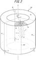
- FIG. 2 illustrates the resin member 200 of FIG. 1 in a state where a polished surface PS along the perpendicular-to-axial direction is formed at a position in the vicinity of the end surface 222 on one side in the axial direction (hereinafter also referred to as polished surface formation position PSP).
- FIG. 3 is a plan view illustrating the polished surface PS of FIG. 2 .
- the polished surface PS is formed by precision polishing using, for example, a rotary polishing machine or a vibration polishing machine.
- the position where the polished surface PS is formed (polished surface formation position PSP) may be any position in the axial direction.
- an angular region (region in the circumferential direction) extending from the angular position of the gate trace G (gate position GP) adjacent to an arbitrarily selected weld portion W on one side in the circumferential direction to the angular position of the gate trace G (gate position GP) adjacent to the weld portion W on the other side in the circumferential direction across the weld portion W is called a between-gate region BGR.
- the between-gate region BGR is an angular region between a pair of gate positions GP adjacent to each other in the circumferential direction with the weld portion W in between.
- the between-gate region BGR is an angular region from the gate position GP to the gate position GP again across the weld portion W.
- the central angle position of the between-gate region BGR is the between-gate position BGP.
- the radial direction at the between-gate position BGP is defined as a Y-axis direction
- a direction parallel to the polished surface PS and perpendicular to the Y-axis direction is defined as a X-axis direction.
- the polished surface PS is parallel to the X-Y plane.
- a direction perpendicular to the X axis and the Y axis is a Z axis, and the Z axis is parallel to the central axis O of the through hole 202.
- the weld portion W is formed approximately along the Y-Z plane.
- the X-axis direction is a direction substantially perpendicularly intersecting the weld portion W (hereinafter also referred to as weld intersecting direction).
- FIG. 4A schematically illustrates the state when observing an enlarged part of the polished surface PS.
- the cross sections FS of a large number of reinforcing fibers F appear on the polished surface PS.
- Most of the reinforcing fibers F are inclined with respect to the polished surface PS, so that the cross sections FS of the reinforcing fibers F appearing on the polished surface PS are usually in an elliptical shape.
- the size and orientation of the elliptical shape formed by the cross section FS of each reinforcing fiber F whose cross section FS appears on the polished surface PS can be specified. In this way, it is possible to understand in which direction the reinforcing fiber F extends in the X-Y-Z space (that is, the orientation of the reinforcing fiber F).
- an azimuth angle ⁇ and an elevation angle ⁇ are used as parameters representing the orientation of each reinforcing fiber F.
- the azimuth angle ⁇ of a reinforcing fiber F means an inclination angle of the central axis FCL of the reinforcing fiber F with respect to the X axis when the central axis FCL is projected on the X-Y plane, as illustrated in FIG. 4C .
- the azimuth angle ⁇ of a reinforcing fiber F is defined by the inclination angle of the major axis of the elliptical shape formed by the cross section FS of the reinforcing fiber F with respect to the X-axis direction.
- the azimuth angle ⁇ can be determined by image processing, for example.
- the elevation angle ⁇ of a reinforcing fiber F means an inclination angle of the central axis FCL of the reinforcing fiber F with respect to the X-Y plane, as illustrated in FIG. 4B , and is defined by the following Equation (1).
- ⁇ Arcsin b / a where a and b are respectively the major axis (major axis length) and the minor axis (minor axis length) of the elliptical shape formed by the cross section FS of the reinforcing fiber F, as illustrated in FIG. 4A .
- the major axis a and the minor axis b can be determined by image processing, for example.
- a virtual arc around the central axis O with a length of 3.5 mm which passes through the center point mrp in the radial direction between the inner circumferential end (end on the inner circumferential side) irp and the outer circumferential end (end on the outer circumferential side) orp of the polished surface PS of the annular portion 201 at the between-gate position BGP and takes the between-gate position BGP as the center, is called an intermediate arc VA, as illustrated in FIG. 3 .
- the circumferential region corresponding to the intermediate arc VA is called an observation region OR.
- Each unit region AA is a fan-shaped virtual region having a central angle ⁇ (°) and an infinite radius.
- the central angle ⁇ of the fan shape formed by the unit region AA is uniquely determined with the radial distance from the central axis O to the intermediate arc VA and the length (0.5 mm) of the intermediate arc portion VAP.
- a region where the unit region AA and the polished surface PS of the annular portion 201 overlap is a region where the fiber orientation tensor Txx is determined.
- the fiber orientation tensor Txx of the unit region AA is defined by the following Equation (2).
- Txx ⁇ cos 2 ⁇ ⁇ ⁇ cos 2 ⁇ / FN
- FN the number of reinforcing fibers F whose cross section FS appears on the polished surface PS in the unit region AA
- ⁇ is the angular position of the angular center (circumferential center) of the unit region AA when the angular position of the between-gate position BGP is defined as 0°, the angular position on one side (left side in FIG. 3 ) in the circumferential direction with respect to the between-gate position BGP is defined as negative (-), and the angular position on the other side (right side in FIG.
- the unit region AA located on the between-gate position BGP has its angular center located at the between-gate position BGP, that is, 0°, and the other unit regions AA have their angular centers located at angular positions corresponding to multiples of ⁇ .
- FN and ⁇ can be determined by image processing, for example.
- the "cos 2 ( ⁇ - ⁇ )cos 2 ⁇ " in Equation (2) corresponds to the index value of X-axis-direction component of a certain reinforcing fiber F (an index value indicating how much the reinforcing fiber is oriented in the X-axis direction).
- the " ⁇ (cos 2 ( ⁇ - ⁇ )cos 2 ⁇ ) ⁇ ” in Equation (2) is the total sum of "cos 2 ( ⁇ - ⁇ )cos 2 ⁇ " of all the reinforcing fibers F whose cross section FS appears in the unit region AA.
- Equation (2) corresponds the average value of "cos 2 ( ⁇ - ⁇ )cos 2 ⁇ " of the reinforcing fibers F whose cross section FS appears in the unit region AA.
- the fiber orientation tensor Txx in a certain unit region AA is the average value of the index value of X-axis-direction component of the reinforcing fibers F whose cross section FS appears in the unit region AA.
- Txx represents how much the reinforcing fibers F whose cross section FS appears in the unit region AA are three-dimensionally oriented in the X-axis direction (weld intersecting direction).
- the fiber orientation tensor Txx is calculated for each unit region AA in the observation region OR, and the calculation result is associated with a circumferential position CP (mm) on the intermediate arc VA of the angular center (circumferential center) of the corresponding unit region AA to be one plot point.
- the absolute value of its value represents the circumferential length when measured along the intermediate arc VA from the origin (0 mm) on the intermediate arc VA, and the sign (positive or negative) of its value indicates the side in the circumferential direction with respect to the origin on the intermediate arc VA.
- the origin (0 mm) of the circumferential position CP on the intermediate arc VA may be any position on the intermediate arc VA.
- the circumferential position CP on the intermediate arc VA at the between-gate position BGP is defined as 0 mm
- the circumferential position CP on one side (left side in FIG. 3 ) in the circumferential direction with respect to the between-gate position BGP is defined as negative (-)
- the circumferential position CP on the other side (right side in FIG. 3 ) in the circumferential direction with respect to the between-gate position BGP is defined as positive (+).
- the unit region AA located on the between-gate position BGP has its circumferential center located at the between-gate position BGP, that is, the circumferential position of 0 mm, and the other unit regions AA have their circumferential centers located at circumferential positions corresponding to multiples of 0.5 mm.
- the fiber orientation tensor waveform is formed by taking the circumferential position CP (mm) on the intermediate arc VA at the angular center (circumferential center) of the unit region AA as the horizontal axis, taking the fiber orientation tensor Txx as the vertical axis, and linearly interpolating the calculated values (plot points) of the fiber orientation tensor Txx of each unit region AA in the observation region OR.
- FIGS. 5A to 5C illustrate different examples of the fiber orientation tensor waveform.
- the orientation of reinforcing fibers (hereinafter also simply referred to as fiber orientation) in a resin member made of a resin containing reinforcing fibers tends to have a higher ratio of components in the direction parallel to a weld portion in the vicinity of the weld portion than in other regions, and tends to be random in more distant regions.
- the fiber orientation of the resin member 200 of the present embodiment has a high ratio of Y-Z-plane-direction component and a low ratio of X-axis-direction component, so that the value of the fiber orientation tensor waveform tends to be lower than 0.333, as in the examples illustrated in FIGS. 5A to 5C .
- the fiber orientation tends to be random (that is, uniformly oriented in the X-axis direction, the Y direction and the Z direction respectively), so that the value of the fiber orientation tensor waveform tends to be around 0.333.
- the "fiber orientation condition" i.e. the condition that "the sum of valley widths HW at half-value Txxh is 1.20 mm or more" in the fiber orientation tensor waveform, will be described with reference to FIGS. 5A to 5C .
- Txxh 0.333 + Txxmin / 2
- the "downward peak Vb" refers to a downward apex where the waveform starts to rise after dropping.
- the waveform portion formed by linearly interpolating these apexes is regarded as one downward peak Vb.
- the "sum of valley widths HW at half-value Txxh" in the fiber orientation tensor waveform is the value of the valley width HW itself when there is only one valley width HW at half-value Txxh in the fiber orientation tensor waveform, as in the example of FIG. 5A or 5B , and refers to the sum of valley widths HW when there are a plurality of valley widths HW at half-value Txxh in the fiber orientation tensor waveform as in the example of FIG. 5C (HW1 + HW2 in the example of FIG. 5C ).
- the "fiber orientation condition" requires that "the sum of valley widths HW at half-value Txxh" be 1.20 mm or more.
- the strength of the weld portion is lower than the strength of other portions in the annular portion.
- the annular portion breaks at the weld portion and is easily destroyed.
- observation region OR is a circumferential region corresponding to an intermediate arc VA around the central axis O with a length of 3.5 mm that passes through the center point mrp in the radial direction between the inner circumferential end irp and the outer circumferential end orp of a polished surface PS of the annular portion 201 at the between-gate position BGP and takes the between-gate position BGP as the center.
- the region where the reinforcing fibers F are highly oriented in the X-axis direction, that is, the weld intersecting direction extends over a wide angle range, and this can greatly improve the strength of the weld portion W and the strength of the annular portion 201 (and the resin member 200), reduce the distortion generated in the vicinity of the weld portion W when, for example, an external force in the diameter expansion direction or the diameter reduction direction is applied to the annular portion 201, and suppress breakage at the weld portion W.
- the circumferential region corresponding to an intermediate arc VA around the central axis O with a length of 3.5 mm which passes through the center point mrp in the radial direction between the inner circumferential end irp and the outer circumferential end orp of a polished surface PS of the annular portion 201 at the between-gate position BGP and takes the between-gate position BGP as the center, is a region close to the between-gate position BGP where a weld portion W tends to be formed and a region where the fiber orientation tends to be very different from other regions.
- the fiber orientation is substantially constant and there is little need for observation.
- the sum can be calculated on the basis of surely taking the region close to the between-gate position BGP into account, and unnecessary calculations can be eliminated. In this way, the fiber orientation of the annular portion 201 can be evaluated accurately and efficiently.
- the resin member 200 of the present embodiment which satisfies the "fiber orientation condition" can improve the strength of the weld portion W.
- the sum of valley widths HW at half-value Txxh is preferably in the range of 1.35 mm or more, and more preferably in the range of 1.50 mm or more. This can further improve the strength of the weld portion W.
- the fiber orientation tensor waveform preferably has only one downward peak Vb, as in the example of FIG. 5A .
- the fiber orientation tensor waveform may have two or more downward peaks Vb as in the examples of FIGS. 5B and 5C .
- the fiber orientation tensor waveform is closer to a waveform having only one downward peak Vb as illustrated in FIG. 5A and the strength of the weld portion W can be further improved.
- the waveform width PD between the pair of downward peaks Vb closest to the between-gate position BGP is preferably 3 mm or less and more preferably 2 mm or less.
- the minimum value Txxmin all over the fiber orientation tensor waveform is preferably 0.14 or more and more preferably 0.15 or more.
- the position in the axial direction at which the polished surface PS is formed (polished surface formation position PSP) in the annular portion 201 is preferably a position in the axial direction within 2 mm from the end surface on either side in the axial direction of the annular portion 201.
- the strength of the weld portion W is particularly required in the vicinity of the end surface rather than the intermediate part in the axial direction of the annular portion 201 in many cases. Therefore, when a polished surface PS is formed in the vicinity of the end surface in the axial direction of the annular portion 201 and the "fiber orientation condition" is satisfied when observing the polished surface PS, it is possible to improve the strength of the weld portion W at a position where particularly high strength is required.
- the polished surface formation position PSP is preferably a position in the axial direction within 2 mm from the end surface 222 on one side in the axial direction of the annular portion 201.
- polished surfaces PS be formed at a plurality of polished surface formation positions PSP in the annular portion 201 as illustrated in FIG. 1 , and the average value of the calculated sum of valley widths HW at half-value Txxh in the fiber orientation tensor waveform obtained by observing each polished surface PS satisfy the "fiber orientation condition". In this way, the strength of the weld portion W can be improved in a wide region in the axial direction.
- all of the plurality of polished surface formation positions PSP are preferably positions in the axial direction within 2 mm from the end surface on either side in the axial direction (in the present example, more preferably the end surface 222 on one side in the axial direction) of the annular portion 201.
- the annular portion 201 may have a female screw in the inner circumferential surface and/or have a male screw in the outer circumferential surface.
- the annular portion 201 receives a force in the diameter expansion direction when an external member with a male screw is screwed into the female screw of the annular portion 201.
- the annular portion 201 receives a force in the diameter reduction direction when the male screw of the annular portion 201 is screwed into an external member with a female screw.
- the resin member 200 of the present embodiment can sufficiently guarantee the strength of the weld portion W, thereby suppressing breakage caused by the cracks of the weld portion W.
- the resin member 200 of the present example is preferably configured as a cylindrical member for a resin joint, and the annular portion 201 preferably constitutes the entire resin member 200. In this way, it is possible to obtain a resin joint with high strength, which will be described in more detail in Specific Examples 1 to 4 illustrated with reference to FIGS. 7 to 27 .
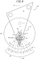
- Embodiment 2 of the present disclosure will be described with reference to FIG. 6 .
- FIG. 6 schematically illustrates a resin member 200 of Embodiment 2.
- the resin member 200 of the present embodiment is different from Embodiment 1 only in shape.
- the resin member 200 is generally formed in a substantially triangular plate shape, and is integrally provided with an annular portion 201 that defines a through hole 202 with a circular cross section at each of the three corners of the resin member 200.
- the axial direction of the through hole 202 is parallel to the plate thickness direction of the resin member 200.
- the shape of the resin member 200 is only schematically illustrated in FIG. 6 for the sake of simplicity.
- the resin member 200 may have a more complicated shape, such as having unevenness in the surface, or changing the inner diameter of the through hole 202 along the axial direction. Even in such a case, the shape of the cross section in the direction perpendicular to the axial direction (perpendicular-to-axial direction) of the through hole 202 is circular.
- the resin member 200 of the present embodiment can be suitably used in a vehicle component, for example.
- a female screw may be formed or may not be formed in the inner circumferential surface defining the through hole 202 of the annular portion 201.
- the resin member 200 in the example of FIG. 6 has only one trace of gate G (hereinafter also referred to as gate trace) formed during the injection molding at the center of the triangular shape formed by the resin member 200.
- gate trace the gate G is illustrated together with the resin member 200 for the sake of convenience.
- the direction of the gate G specified from the gate trace G is toward one side in the axial direction.
- the between-gate position BGP is at an angular position equidistant from the gate position G along the circumferential direction around the central axis O of the through hole 202 for each through hole 202.
- each through hole 202 has one gate position GP and one between-gate position BGP.
- FIG. 6 illustrates a gate position GP and a between-gate position BGP corresponding to one through hole 202 for the sake of convenience.
- Each annular portion 201 is formed with a weld portion W. Although a weld portion W is formed in the vicinity of each of the three between-gate positions BGP, only one of the weld portions W is illustrated in the example of FIG. 6 , for the sake of convenience.
- the resin member 200 of the present embodiment is in a similar manner with that of Embodiment 1, where, when a polished surface PS along the perpendicular-to-axial direction is formed in the annular portion 201, the annular portion 201 satisfies the condition that "the sum of valley widths HW at half-value Txxh in a fiber orientation tensor waveform is 1.20 mm or more" ("fiber orientation condition").
- the shape of the annular portion 201 of the resin member 200 is not limited to the above-described example, and may be any shape as long as it defines a through hole 202 with a circular cross section.
- the condition that "the sum of valley widths HW at half-value Txxh in a fiber orientation tensor waveform is 1.20 mm or more" can be realized in the annular portion of the resin member of the present disclosure by, for example, refining the shape of the mold during the injection molding and the shape of the resin member.
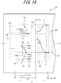
- FIGS. 7 to 11 illustrate an injection mold 100 of the present example in a closed state
- FIGS. 12A and 12B illustrate opening the injection mold 100 and taking out a resin member 200 as a molded article
- FIGS. 13A and 13B illustrate a resin member 200 of the present example, which is obtained by injection molding with the injection mold 100 of FIGS. 7 to 12B .
- the resin member 200 may be used in resin products of any type and application, and is suitably used in a joint.
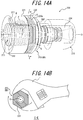
- FIGS. 14A and 14B illustrate a joint 300, which is an example of a final resin product obtained with the resin member 200 of FIGS. 13A and 13B .
- the injection mold (hereinafter also simply referred to as mold) 100 of the present example has a cavity CV defined by a cavity surface, at least one (three in the present example) gate G which is an injection port for injecting molten resin containing reinforcing fibers conveyed by a runner R into the cavity CV, and at least one (three in the present example) resin reservoir 110 which is a concave portion open to the cavity CV.
- the mold 100 is configured such that resins join together inside the cavity CV to form a weld portion W that is hardened in a state where the resin interfaces push each other, which will be described in detail later.
- the resin reservoir 110 is provided to improve the strength of the weld portion W.
- the resin member 200 of the present example is produced with the following method.
- the mold 100 is closed and a cavity CV is formed inside.
- molten resin containing reinforcing fibers flows from the runner R toward the gate G and is injected from the gate G into the cavity CV.
- the resin inside the cavity CV is cooled and cured to a predetermined degree.
- the mold 100 is opened to take out a resin member 200.
- the molding step of a resin member 200 is completed, and a resin member 200 made of a resin containing reinforcing fibers as illustrated in FIGS. 13A and 13B is obtained.
- the resin member 200 has a main body MB and at least one (three in the present example) projection 210 connected to the main body MB.
- the main body MB is molded by the cavity CV, and the projection 210 is molded by the resin reservoir 110.
- the resin member 200 obtained by the molding step may be used as a final resin product as it is.
- the resin member 200 may, after the molding step, be further processed or assembled with another member to obtain a final resin product.
- the projection 210 of the resin member 200 may be removed by cutting or other means (removal step).
- the main body MB of the resin member 200 corresponds to the annular portion 201 in Embodiment 1.
- the joint 300 of FIGS. 14A and 14B is obtained by removing the projection 210 from the resin member 200 ( FIGS. 13A and 13B ) obtained by the molding step and attaching an outer cylinder 310 to the main body MB (assembly step).
- the joint 300 is suitably used in pipes for supplying water and hot water, and can also be used in pipes for fluids other than water (for example, liquids such as oil and liquid medicines, and gases such as air and gas).
- a trace 211 of the removed projection 210 may remain in the main body MB.
- the main body MB of the resin member 200 is a cylindrical member extending straight.
- the main body MB has an one-axial-side portion 221 located on one side in the axial direction of the main body MB, an axial-middle portion 220 located in the middle in the axial direction of the main body MB, and an other-axial-side portion 224 located on the other side in the axial direction of the main body MB.
- the "cylindrical member” is not limited to a member in a shape where both the outer circumferential surface and the inner circumferential surface have a circular cross section along the entire length.
- the “cylindrical member” also includes a member in a shape that is substantially cylindrical when viewed as a whole, and the outer circumferential surface and/or the inner circumferential surface may have a non-circular cross section at least in part of the extending direction.
- the resin member 200 has a female screw 223 in the inner circumferential surface of the region extending from the one-axial-side portion 221 to the axial-middle portion 220.
- the female screw 223 is configured to be connected to a male screw of another member (for example, a metal water pipe) not illustrated in the figure.
- the female screw 223 is a tapered female screw that gradually decreases in diameter from the one axial side toward the other axial side (back side) of the main body MB.
- the projection 210 is connected to an end surface 222 on the one axial side of the main body MB.
- the "axial direction" of the resin member 200 or the main body MB refers to a direction parallel to the central axis O of the cylindrical shape formed by the main body MB.
- the central axis O extends in a straight line.
- the "one axial side” of the resin member 200 or the main body MB refers to the side on which the female screw 223 is formed of the two sides in the axial direction
- the "other axial side” of the resin member 200 or the main body MB refers to the opposite side.
- the "perpendicular-to-axial direction" of the resin member 200 or the main body MB refers to a direction perpendicular to the axial direction.
- the resin member 200 of the present example is made of a resin containing reinforcing fibers.
- any resin may be used as the resin of the resin member 200.
- PPS polyphenylene sulfide
- the reinforcing fibers in the resin of the resin member 200 are contained to improve the strength of the resin.
- the reinforcing fibers may be any fibers as long as they improve the strength of the resin.
- glass fibers for example, may be used as the reinforcing fibers because they can improve the strength of the resin member 200 and the strength of the joint 300, specifically, they can improve the crack resistance and the creep deformation resistance.
- the entire resin member 200 including the female screw 223 is integrally formed of resin, so that the weight and the cost of the resin member 200 and the joint 300 can be reduced as compared with the case where at least a part of the resin member 200 (for example, only the female screw 223) is made of metal.
- the resin member 200 since the resin member 200 includes reinforcing fibers in the resin, it is possible to ensure the same strength as in the case where at least a part is made of metal.
- the outer circumferential surfaces of the one-axial-side portion 221 and the other-axial-side portion 224 of the resin member 200 have a circular cross section in the perpendicular-to-axial direction.
- the outer circumferential surface of the axial-middle portion 220 of the resin member 200 has a polygonal (hexagonal in the present example) cross section in the perpendicular-to-axial direction, thereby forming a torque input portion 220.
- the outer circumferential surface of the torque input portion 220 has a polygonal cross section in the perpendicular-to-axial direction. Therefore, when the female screw 223 is tightened against a male screw of another member during construction of the joint 300, for example, a tool T such as a wrench as illustrated in FIG. 14B grips a pair of opposed flat faces of the torque input portion 220 from the outside and the torque from the tool T is properly input.
- a plurality of concave portions 220a are formed in the outer circumferential surface of the torque input portion 220.
- the outer diameter of the one-axial-side portion 221 and the outer diameter of the torque input portion 220 are substantially the same, and are almost constant along the axial direction.
- the end portion of the tapered female screw 223 is formed in the inner circumferential surface of the torque input portion 220, that is, the inner diameter thereof is slightly smaller than that of the one-axial-side portion 221. In this way, the circumferential wall thickness and the strength of the torque input portion 220 are guaranteed to withstand the torque from the above-described tool T.
- the outer diameter of the other-axial-side portion 224 is much smaller than the outer diameters of the one-axial-side portion 221 and the torque input portion 220.
- an outer cylinder 310 having a larger diameter is attached to the other-axial-side portion 224.
- An annular space is defined between the other-axial-side portion 224 of the resin member 200 and the outer cylinder 310, and this annular space is configured such that a circular tubular member (for example, a pipe made of polybutene or cross-linked polyethylene) not illustrated in the figure can be inserted therein.
- the projection 210 will be described in more detail later.
- the mold 100 has outer mold portions 101 to 104 and inner mold portions 105 and 106.
- a cavity CV is defined by the inside cavity surfaces of the outer mold portions 101 to 104 and the outside cavity surfaces of the inner mold portions 105 and 106.
- the cavity CV is configured in a cylindrical shape extending straight, by which the main body MB of the resin member 200, which is a cylindrical member, is molded.
- the outer mold portion 101 which is located closest to the one axial side among the outer mold portions 101 to 104, has a cavity surface 122 for one-axial-side end surface which is configured to mold the one-axial-side end surface 222 of the resin member 200.
- the other outer mold portions 102 to 104 are arranged circumferentially on the other axial side with respect to the outer mold portion 101, and each of them has a cavity surface for outer circumferential surface which is configured to mold an outer circumferential surface along the entire length of the main body MB of the resin member 200.
- Each of the cavity surfaces for outer circumferential surface of the outer mold portions 102 to 104 has a cavity surface 121 for one-axial-side portion which is configured to mold the outer circumferential surface of the one-axial-side portion 221 of the resin member 200, a cavity surface 120 for torque input portion which is configured to mold the outer circumferential surface of the torque input portion 220 of the resin member 200, and a cavity surface 124 for other-axial-side portion which is configured to mold the outer circumferential surface of the other-axial-side portion 224 of the resin member 200, respectively.
- the inner mold portion 105 which is located on the one axial side of the inner mold portions 105 and 106, has a cavity surface 123 for female screw which is configured to mold the female screw 223 of the resin member 200, and a part on the one axial side of the cavity surface 123 for female screw is configured to be accommodated in an inner mold accommodating portion 101a ( FIG. 12A ) provided in the outer mold portion 101.
- the cavity surface 123 for female screw gradually decreases in diameter as it goes from the one axial side to the other axial side (back side) of the cavity CV.
- the other inner mold portion 106 has a cavity surface 125 for other-axial-side portion which is configured to mold the inner circumferential surface of the other-axial-side portion 224 of the resin member 200.
- the outer mold portion 101 has a resin reservoir 110, and the resin reservoir 110 is open to the cavity surface 122 for one-axial-side end surface.
- the resin reservoir 110 is a portion where a part of molten resin in the cavity CV flows and accumulates when the molten resin is injected into the cavity CV, and a portion where the projection 210 of the resin member 200 is molded.
- the "axial direction" of the mold 100 or the cavity CV refers to a direction parallel to the central axis O of the cylindrical shape formed by the cavity CV.
- the central axis O extends in a straight line.
- the "one axial side” of the mold 100 or the cavity CV refers to the side where the cavity surface 123 for female screw is arranged of the two sides in the axial direction
- the "other axial side” of the mold 100 or the cavity CV refers to the opposite side.
- the "perpendicular-to-axial direction" of the mold 100 or the cavity CV refers to a direction perpendicular to the axial direction.
- the outer mold portions 102 to 104 are each removed radially outward from the resin member 200, which is a molded article, and the outer mold portion 101 is removed from the resin member 200 to the one axial side, as illustrated in FIGS. 12A and 12B .
- the inner mold portion 105 is rotated and pulled out from the resin member 200 to the one axial side, and the inner mold portion 106 is pulled out from the resin member 200 to the other axial side.
- a cavity CV similar to that of the present example may be defined by outer mold portions and inner mold portions which have different structures from the outer mold portions 101 to 104 and the inner mold portions 105 and 106 of the present example.
- the mold 100 is in a closed state unless otherwise specified.
- the cavity surface 121 for one-axial-side portion and the cavity surface 124 for other-axial-side portion have a circular cross section in the perpendicular-to-axial direction.
- the cavity surface 120 for torque input portion has a polygonal (hexagonal in the present example) cross section in the perpendicular-to-axial direction.
- a plurality of convex portions 120a FIG. 10
- a plurality of concave portions 220a in the torque input portion 220 of the resin member 200 are formed in the cavity surface 120 for torque input portion.
- the outer diameter of the cavity surface 121 for one-axial-side portion and the outer diameter of the cavity surface 120 for torque input portion are substantially the same.
- the end portion of the cavity surface 123 for female screw is arranged on the inner circumferential side of the cavity surface 120 for torque input portion, that is, the inner diameter of the cavity CV there is slightly smaller than that of the cavity surface 121 for one-axial-side portion.
- the outer diameter of the cavity surface 124 for other-axial-side portion is much smaller than the outer diameter of the cavity surface 121 for one-axial-side portion and the outer diameter of the cavity surface 120 for torque input portion.
- a gate G which is directed to the one axial side and open to the cavity CV, is provided on the other axial side of the cavity surface 120 for torque input portion. More specifically, in the present example, the gate G is provided in the vicinity of the other-axial-side end portion of the cavity surface 120 for torque input portion. In the illustrated example, three gates G are provided at equal intervals in the circumferential direction (at angular positions distanced by 120°). As used herein, the "angular position" in the mold 100 or the resin member 200 refers to an angular position around the central axis O and corresponds to a circumferential position.
- the resin reservoir 110 is open to the cavity surface 122 for one-axial-side end surface.
- the resin reservoir 110 extends toward the one axial side, and more specifically, extends along the axial direction.
- the gate G is directed to the one axial side of the cavity CV, and is configured to inject the molten resin toward the one axial side (along the axial direction in the present example) inside the cavity CV. That is, in the present example, the extending direction of the resin reservoir 110 is substantially the same as the direction of the gate G and the resin flow direction. However, the extending direction of the resin reservoir 110 may be a direction inclined to the axial direction.
- the molten resin containing reinforcing fibers when molten resin containing reinforcing fibers is injected from the gate G into the cavity CV, the molten resin first spreads in the circumferential direction and moves toward the one axial side in the axial direction, first inside the cavity CV that is on the inside of the cavity surface 120 for torque input portion and then inside the cavity CV that is on the inside of the cavity surface 121 for one-axial-side portion, and then flows into the resin reservoir 110.
- the resin then flows toward the other axial side in the axial direction, inside the cavity CV on the inside of the cavity surface 124 for other-axial-side portion, to fill it with the resin. In this way, the entire cavity CV is filled with the resin.
- the weld portion W tends to be formed in a planar shape parallel to the axial direction and the radial direction at each between-gate position BGP, which is a position (angular position) equidistant between gate positions GP, i.e. the position (angular position) of each gate G, along the cavity CV, in the cavity CV on the inside of the cavity surface 121 for one-axial-side portion which is away from the gate G in the resin flow direction (the axial direction in the present example).
- the "resin flow direction” is a direction approximating the rough direction in which the resin injected from the gate G flows in the cavity CV. In the present example, it corresponds to the direction of the gate G and the direction toward the one axial side.
- the "weld extending direction” is a direction approximating the extending direction of the weld portion W to one direction, and corresponds to a direction approximating the extending direction of a virtual plane passing through the between-gate position BGP to one direction. In the present example, it is the axial direction.
- a direction intersecting the weld extending direction may be referred to as a "weld intersecting direction".
- the interface of the high-temperature resins just injected from the gate G during the injection disappears and hardly remains even if the resins join together, rendering it difficult to form a weld portion W.
- the resin flows far from the gate G, that is, the resin flows close to the one-axial-side end surface 222, the resin cools with the time elapsed from the injection from the gate G increasing.
- the interface tends to remain and a weld portion W tends to be formed.
- the resin member 200 as a molded article may not have sufficient strength against the external force in the radial direction. Even if the resin is reinforced with the reinforcing fibers F, when the reinforcing fibers F in the weld portion W are each oriented parallel to the extending direction of the weld portion W, the strength of the weld portion W is actually only the strength of the resin.
- the resin member 200 of the present example has a female screw 223 on the inner circumferential side of the one-axial-side portion 221 and the torque input portion 220, and therefore during construction of the joint 300, for example, the one-axial-side portion 221 and the torque input portion 220 receive a force in the radially expanding direction once an external member with a male screw is screwed into the female screw 223.
- the weld portion W formed in the one-axial-side portion 221 does not have sufficient strength, the one-axial-side portion 221 may be damaged. Therefore, the weld portion W is required to have sufficient strength.
- the female screw 223 of the present example is a tapered female screw
- the circumferential wall thickness of the one-axial-side portion 221 is smaller than that of the torque input portion 220, and the thickness decreases as it gets close to the one-axial-side end surface 222.
- the force in the radially expanding direction input by the external member with a male screw may increase as compared with the case where the female screw 223 is a parallel female screw. Accordingly, it is highly necessary to improve the strength of the weld portion W, and in particular, the necessity increases as it gets close to the one-axial-side end surface 222.
- the mold 100 is provided with a resin reservoir 110, and the resin reservoir 110 is open to the cavity surface 122 for one-axial-side end surface, as described above.
- the resin reservoir 110 extends toward the one axial side, and more specifically, extends in the axial direction.
- the shape of the weld portion W formed in the vicinity of the between-gate position BGP is not a shape that extends straight in the axial direction, but a shape that is complicatedly disturbed in three dimensions, such as a blurred shape, a slanted shape, or a bent shape when viewed three-dimensionally.
- the strength of the weld portion W thus can be improved.
- the direction of the reinforcing fibers F in the resin is disturbed and the reinforcing fibers F are three-dimensionally oriented in various directions. Therefore, the ratio of the reinforcing fibers F oriented in a direction intersecting the axial direction and in a weld intersecting direction is increased. This also improves the strength of the weld portion W.
- the resin reservoir 110 is open to a cavity surface for outer circumferential surface (for example, the cavity surface 121 for one-axial-side portion or the cavity surface 120 for torque input portion) and extends in the radial direction.
- the projection 210 molded by the resin reservoir 110 having the above-described structure has the following structure.
- the projection 210 is connected to the one-axial-side end surface 222.
- the projection 210 extends toward the one axial side, and more specifically, extends in the axial direction. That is, in the present example, the extending direction of the projection 210 is substantially the same as the direction of the gate G and the resin flow direction. However, the extending direction of the projection 210 may be a direction inclined to the axial direction.
- the gate G, the gate position GP, and the between-gate position BGP are illustrated together with the resin member 200 for the sake of convenience.
- a trace of the gate G formed during the injection molding may remain at the position of the gate G in the resin member 200.
- the position of the gate G and the direction of the gate G (and the direction in which the resin is injected from the gate G, the one axial side in the present example) can be specified.
- the resin flow direction inside the cavity CV, the gate position GP, and the between-gate position BGP can be specified.
- the shape of the weld portion W formed in the vicinity of the between-gate position BGP in the one-axial-side portion 221 during the injection molding is not a shape that extends straight in the axial direction, but a shape that is complicatedly disturbed in three dimensions, as described above with respect to the working effects of the resin reservoir 110 of the mold 100.
- the strength of the weld portion W thus can be improved.
- the direction of the reinforcing fibers F in the resin is disturbed and the reinforcing fibers F are three-dimensionally oriented in various directions. Therefore, the ratio of the reinforcing fibers F oriented in a direction intersecting the axial direction and in a weld intersecting direction is increased. This also improves the strength of the weld portion W.
- the projection 210 is connected to the outer circumferential surface of the main body MB (for example, the outer circumferential surface of the one-axial-side portion 221 or the outer circumferential surface of the torque input portion 220) and extends in the radial direction.
- the three resin reservoirs 110 of the mold 100 have the same structure with each other, and when the three resin reservoirs 110 are viewed as a unit, the structure is made to be 120-degree symmetrical (also referred to as three-fold symmetrical) so as to overlap with itself when rotated around the central axis O of the cavity CV by 120° (360°/3).
- the structure when the n resin reservoirs 110 are viewed as a unit may be made to be (360/n)-degree symmetrical (also referred to as n-fold symmetrical) so as to overlap with itself when rotated around the central axis O of the cavity CV by (360/n)°.
- the plurality of resin reservoirs 110 of the mold 100 may have different structures from each other.
- FIGS. 13A and 13B is in a similar manner with the above, where the three projections 210 of the resin member 200 have the same structure with each other, and when the three projections 210 are viewed as a unit, the structure is made to be 120-degree symmetrical (also referred to as three-fold symmetrical) so as to overlap with itself when rotated around the central axis O of the main body MB by 120°.
- 120-degree symmetrical also referred to as three-fold symmetrical
- the structure when the n projections 210 are viewed as a unit may be made to be (360/n)-degree symmetrical (also referred to as n-fold symmetrical) so as to overlap with itself when rotated around the central axis O of the main body MB by (360/n)°.
- the plurality of projections 210 of the resin member 200 may have different structures from each other.
- the structure and working effects of the resin member 200 correspond to the structure and working effects of the mold 100.
- the following describes the structure and working effects of the mold 100 and the structure of the resin member 200, and may omit the description of the working effects of the resin member 200.
- the opening end surface 110S of the resin reservoir 110 to the cavity CV (the boundary surface between the resin reservoir 110 and the cavity CV) is formed in a non-circular shape. More specifically, in the present example, the opening end surface 110S is formed in a parallelogram where the length in one direction is longer than the length in the direction perpendicular thereto.
- the distance CLD between a width center line CL11 of the resin reservoir 110 and a width center line CL12 of the cavity CV, which is measured along a perpendicular line n12 of the width center line CL12 of the cavity CV, is not always constant and changes at least in part along the width center line CL12 of the cavity CV.
- the "first cross section" along the opening end surface 110S is a cross section of the mold 100 along a virtual plane including the opening end surface 110S.
- the first cross section is a cross section parallel to the perpendicular-to-axial direction, and is the cross section of FIG. 9B (the cross section along the line C-C in FIGS. 8A and 8B ).
- the "width center line CL11" of the resin reservoir 110 in the first cross section refers to a line passing through the center of the width direction of the opening end surface 110S, where the width direction is the direction perpendicular to the extending direction (longitudinal direction) of the opening end surface 110S in the first cross section. In the present example, it is a line equidistant from two opposed long sides of the parallelogram formed by the opening end surface 110S.
- the "perpendicular line n11" of the width center line CL11 of the resin reservoir 110 in the first cross section is a line that is perpendicular to a tangent at an arbitrary point on the width center line CL11 of the resin reservoir 110 and passes through the point.
- the "width center line CL12" of the cavity CV in the first cross section is a line passing through the center of the width direction of the cavity CV, where the width direction is the direction perpendicular to the extending direction (longitudinal direction) of the cavity CV in the first cross section. In the present example, it is a line equidistant from the outer circumferential periphery and the inner circumferential periphery of the annular shape formed by the cavity CV in the first cross section.
- the "perpendicular line n12" of the width center line CL12 of the cavity CV in the first cross section is a line that is perpendicular to the tangent at an arbitrary point on the width center line CL12 of the cavity CV and passes through the point.
- the resin flow is disturbed in a wide range in the width direction of the cavity CV in the cross section perpendicular to the axis (the direction perpendicular to the extending direction of the cavity CV; the thickness direction of the cavity CV) and the resin flows in various directions in three dimensions immediately before the molten resin flows into the resin reservoir 110 during the injection.
- the shape of the weld portion W formed in the vicinity of the between-gate position BGP is a shape that is complicatedly disturbed in three dimensions. The strength of the weld portion W thus can be improved.
- the reinforcing fibers F are three-dimensionally oriented in various directions in a wide range in the width direction of the cavity CV in the cross section perpendicular to the axis. Therefore, the ratio of the reinforcing fibers F oriented in a direction intersecting the axial direction and in a weld intersecting direction is increased. This also improves the strength of the weld portion W.
- the distance CLD between the width center line CL11 of the resin reservoir 110 and the width center line CL12 of the cavity CV, which is measured along the perpendicular line n12 of the width center line CL12 of the cavity CV, is always constant along the width center line CL12 of the cavity CV in the first cross section, then the flow direction of the resin and the orientation direction of the reinforcing fibers F cannot be disturbed in a complicated manner or in a wide range in the width direction of the cavity CV in the cross section perpendicular to the axis in the vicinity of the between-gate position BGP and in the vicinity of the weld portion W.
- the projection 210 is in a similar manner with the above, where a connecting end surface 210S of the projection 210 to the main body MB (the boundary surface between the projection 210 and the main body MB) is formed in a non-circular shape, as illustrated in FIG. 13B . More specifically, in the present example, the connecting end surface 210S is formed in a parallelogram where the length in one direction is longer than the length in the direction perpendicular thereto.
- the distance CLD' between a width center line CL21 of the projection 210 and a width center line CL22 of the main body MB, which is measured along a perpendicular line n22 of the width center line CL22 of the main body MB, changes at least in part along the width center line CL22 of the main body MB (always changes in the illustrated example).
- the "first cross section" along the connecting end surface 210S is a cross section of the resin member 200 along a virtual plane including the connecting end surface 210S.
- the first cross section is a cross section parallel to the perpendicular-to-axial direction.
- the "width center line CL21" of the projection 210 in the first cross section refers to a line passing through the center of the width direction of the connecting end surface 210S, where the width direction is the direction perpendicular to the extending direction (longitudinal direction) of the connecting end surface 210S in the first cross section. In the present example, it is a line equidistant from two opposed long sides of the parallelogram formed by the connecting end surface 210S.
- the "width center line CL22" of the main body MB in the first cross section is a line passing through the center of the width direction of the main body MB, where the width direction is the direction perpendicular to the extending direction (longitudinal direction) of the main body MB in the first cross section. In the present example, it is a line equidistant from the outer circumferential periphery and the inner circumferential periphery of the annular shape formed by the main body MB in the first cross section.
- the "perpendicular line n22" of the width center line CL22 of the main body MB in the first cross section is a line that is perpendicular to the tangent at an arbitrary point on the width center line CL22 of the main body MB and passes through the point, when the width center line CL22 of the main body MB is nonlinear as in the present example.
- the width center line CL11 of the resin reservoir 110 extends in a direction intersecting at a non-right angle with respect to the width center line CL12 of the cavity CV in the first cross section along the opening end surface 110S of the resin reservoir 110 to the cavity CV.
- the width center line CL11 of the resin reservoir 110 is linear
- the width center line CL12 of the cavity CV is nonlinear (circular).
- the width center line CL11 of the resin reservoir 110 extends in a direction intersecting at a non-right angle" with respect to the width center line CL12 of the cavity CV in the first cross section mean that at the intersection of the width center line CL11 of the resin reservoir 110 (the extension line of the width center line CL11 of the resin reservoir 110 if the width center line CL11 of the resin reservoir 110 does not intersect the width center line CL12 of the cavity CV) and the width center line CL12 of the cavity CV in the first cross section, the smaller intersection angle ⁇ between the tangent of the width center line CL11 of the resin reservoir 110 and the tangent of the width center line CL12 of the cavity CV at the intersection is greater than 0° and less than 90°.
- the shape of the weld portion W and the orientation (extending direction) of the reinforcing fibers F in the vicinity of the between-gate position BGP and in the vicinity of the weld portion W can be disturbed in a wider range and more complicatedly than in the case where the width center line CL11 of the resin reservoir 110 does not extend in a direction intersecting at a non-right angle with respect to the width center line CL12 of the cavity CV, that is, in the case where the width center line CL11 of the resin reservoir 110 extends in a direction along the width center line CL12 of the cavity CV, or extends in a direction perpendicular to the width center line CL12 of the cavity CV (the radial direction in the present example), for example.
- the strength of the weld portion W can be improved.
- the resin member 200 of FIGS. 13A and 13B is in a similar manner with the above, where the width center line CL21 of the projection 210 extends in a direction intersecting at a non-right angle with respect to the width center line CL22 of the main body MB in the first cross section along the connecting end surface 210S of the projection 210 to the main body MB.
- the width center line CL21 of the projection 210 is linear
- the width center line CL22 of the main body MB is nonlinear (circular).
- the width center line CL21 of the projection 210 extends in a direction intersecting at a non-right angle" with respect to the width center line CL22 of the main body MB in the first cross section mean that at the intersection of the width center line CL21 of the projection 210 (the extension line of the width center line CL21 of the projection 210 if the width center line CL21 of the projection 210 does not intersect the width center line CL22 of the main body MB) and the width center line CL22 of the main body MB in the first cross section, the smaller intersection angle ⁇ ' between the tangent of the width center line CL21 of the projection 210 and the tangent of the width center line CL22 of the main body MB at the intersection is greater than 0° and less than 90°.
- the mold 100 that at the intersection of the width center line CL11 of the resin reservoir 110 (the extension line of the width center line CL11 of the resin reservoir 110 if the width center line CL11 of the resin reservoir 110 does not intersect the width center line CL12 of the cavity CV) and the width center line CL12 of the cavity CV in the first cross section, the smaller intersection angle ⁇ between the tangent of the width center line CL11 of the resin reservoir 110 and the tangent of the width center line CL12 of the cavity CV at the intersection be 10° to 30°.
- the resin member 200 is in a similar manner with the above, where at the intersection of the width center line CL21 of the projection 210 (the extension line of the width center line CL21 of the projection 210 if the width center line CL21 of the projection 210 does not intersect the width center line CL22 of the main body MB) and the width center line CL22 of the main body MB in the first cross section, the smaller intersection angle ⁇ ' between the tangent of the width center line CL21 of the projection 210 and the tangent of the width center line CL22 of the main body MB at the intersection is preferably 10° to 30°.
- the width center line CL11 of the resin reservoir 110 in the first cross section not only extends in a direction intersecting at a non-right angle with respect to the width center line CL12 of the cavity CV in the first cross section, but also actually intersects at a non-right angle with respect to the width center line CL12.
- the shape of the weld portion W and the orientation (extending direction) of the reinforcing fibers F in the vicinity of the between-gate position BGP and in the vicinity of the weld portion W can be disturbed in a wider range and more complicatedly than in the case where there is no actual intersection. As a result, the strength of the weld portion W can be improved.
- the resin member 200 of FIGS. 13A and 13B is in a similar manner with the above, where the width center line CL21 of the projection 210 in the first cross section not only extends in a direction intersecting at a non-right angle with respect to the width center line CL22 of the main body MB in the first cross section, but also actually intersects at a non-right angle with respect to the width center line CL22.
- the width center line CL11 of the resin reservoir 110 in the first cross section has a part where the distance to the central axis O of the cavity CV is not constant over the entire length and changes along the width center line CL11. More specifically, in the present example, the distance from the width center line CL11 of the resin reservoir 110 in the first cross section to the central axis O of the cavity CV changes along the width center line CL11 over the entire length.
- the shape of the weld portion W and the orientation (extending direction) of the reinforcing fibers F in the vicinity of the between-gate position BGP and in the vicinity of the weld portion W can be disturbed in a wider range and more complicatedly.
- the strength of the weld portion W can be improved.
- the resin member 200 of FIGS. 13A and 13B is in a similar manner with the above, where the width center line CL21 of the projection 210 in the first cross section has a part where the distance to the central axis O of the main body MB is not constant over the entire length and changes along the width center line CL21. More specifically, in the present example, the distance from the width center line CL21 of the projection 210 in the first cross section to the central axis O of the main body MB changes along the width center line CL21 over the entire length.
- the distance from the end portion on one side of the width center line CL11 of the resin reservoir 110 in the first cross section to the central axis O of the cavity CV is longer than the distance from the end portion on the other side of the width center line CL11 to the central axis O of the cavity CV. More specifically, for the width center line CL11 of the resin reservoir 110 in the first cross section of the present example, the distance to the central axis O of the cavity CV gradually increases from the end portion on one side toward the end portion on the other side of the width center line CL11 over the entire length.
- the shape of the weld portion W and the orientation of the reinforcing fibers F in the vicinity of the between-gate position BGP and in the vicinity of the weld portion W can be disturbed in a wider range and more complicatedly.
- the strength of the weld portion W can be improved.
- the resin member 200 of FIGS. 13A and 13B is in a similar manner with the above, where the distance from the end portion on one side of the width center line CL21 of the projection 210 in the first cross section to the central axis O of the main body MB is longer than the distance from the end portion on the other side of the width center line CL21 to the central axis O of the main body MB. More specifically, for the width center line CL21 of the projection 210 in the first cross section of the present example, the distance to the central axis O of the main body MB gradually increases from the end portion on one side toward the end portion on the other side of the width center line CL21 over the entire length.
- the outer edge of the opening end surface 110S of the resin reservoir 110 to the cavity CV is formed in a parallelogram shape with non-perpendicular diagonals.
- the shape of the weld portion W and the orientation of the reinforcing fibers F in the vicinity of the between-gate position BGP and in the vicinity of the weld portion W can be disturbed in a wider range and more complicatedly.
- the strength of the weld portion W can be improved.
- the resin member 200 of FIGS. 13A and 13B is in a similar manner with the above, where the outer edge of the connecting end surface 210S of the projection 210 to the main body MB is formed in a parallelogram shape with non-perpendicular diagonals.
- the opening end surface 110S of the resin reservoir 110 to the cavity CV does not overlap with the between-gate position BGP, and is at a position (angular position) deviated from the between-gate position BGP (and the weld portion W).
- the molten resin tends to flow toward the resin reservoir 110 and away from the between-gate position BGP before flowing into the resin reservoir 110 during the injection, as schematically illustrated in FIG. 11 .
- the resin flow is disturbed in the vicinity of the between-gate position BGP and in the vicinity of the weld portion W, so that the shape of the weld portion W and the orientation of the reinforcing fibers F in the vicinity of the between-gate position BGP and in the vicinity of the weld portion W can be disturbed in a wider range and more complicatedly.
- the strength of the weld portion W can be improved.
- the resin member 200 of FIGS. 13A and 13B is in a similar manner with the above, where the connecting end surface 210S of the projection 210 to the main body MB does not overlap with the between-gate position BGP, and is at a position (angular position) deviated from the between-gate position BGP (and the weld portion W).
- the opening end surface 110S of the resin reservoir 110 to the cavity CV does not overlap with the gate position GP, and is at a position (angular position) between the gate position GP and the between-gate position BGP.
- the opening end surface 110S of the resin reservoir 110 is not too far from the between-gate position BGP, which can effectively urge the molten resin in the vicinity of the between-gate position BGP to flow toward the resin reservoir 110.
- the resin member 200 of FIGS. 13A and 13B is in a similar manner with the above, where the connecting end surface 210S of the projection 210 to the main body MB does not overlap with the gate position GP, and is at a position (angular position) between the gate position GP and the between-gate position BGP.
- the area of the cross section perpendicular to the axial direction (the extending direction of the resin reservoir 110 in the present example) of the resin reservoir 110 is largest at the opening end surface 110S to the cavity CV. More specifically, in the illustrated example, the area of the cross section perpendicular to the axial direction (the extending direction of the resin reservoir 110 in the present example) of the resin reservoir 110 is constant from the opening end surface 110S (base) to the front of the tip portion, and only at the tip portion located on the most tip side, the cross section area gradually decreases as it goes toward the tip.
- the effect of the resin reservoir 110 of disturbing the resin flow can be increased.
- the resin member 200 of FIGS. 13A and 13B is in a similar manner with the above, where the area of the cross section perpendicular to the axial direction (the extending direction of the projection 210 in the present example) of the projection 210 is largest at the connecting end surface 210S to the main body MB. More specifically, in the illustrated example, the area of the cross section perpendicular to the axial direction (the extending direction of the projection 210 in the present example) of the projection 210 is constant from the connecting end surface 210S (base) to the front of the tip portion, and only at the tip portion located on the most tip side, the cross section area gradually decreases as it goes toward the tip.
- the mold 100 may be configured in a way where the cavity CV does not form a female screw 223. In that case, the weld portion W may not be required to have a high strength. However, the mold 100 may be configured such that the cavity CV forms a female screw 223 in the inner circumferential surface of at least one side in the axial direction of the main body MB which is a cylindrical member, as in the present example. Even in such a case, the strength of the weld portion can be sufficiently guaranteed.
- the resin member 200 is in a similar manner with the above, where the main body MB, which is a cylindrical member, may have no female screw 223, or may have a female screw in the inner circumferential surface of at least one side in the axial direction of the main body MB, as in the present example.
- the resin reservoir 110 be open to a cavity surface for molding the end surface 222 on the side where the female screw 223 is molded (the cavity surface 122 for one-axial-side end surface in the present example) of the two sides in the axial direction of the main body MB which is a cylindrical member, as in the present example.
- the strength of the weld portion W can be sufficiently guaranteed around the female screw where strength is particularly required.
- the resin member 200 is in a similar manner with the above, where in the case of having a female screw 223, it is preferable that the projection 210 be connected to an end surface on the side having the female screw 223 (the one-axial-side end surface 222 in the present example) of the two sides in the axial direction of the main body MB which is a cylindrical member, as in the present example.
- FIGS. 15A , 15B and 16 illustrate a mold 100 of the present example.
- FIGS. 17A and 17B illustrate a resin member 200 of the present example.
- Specific Example 2 is different from Specific Example 1 only in the shape of the resin reservoir 110 of the mold 100 and the shape of the projection 210 of the resin member 200.
- the structure of the cavity CV and the arrangement of the resin reservoir 110 of the mold 100, and the structure of the main body MB and the arrangement of the projection 210 of the resin member 200 are the same as that of Specific Example 1.
- the resin reservoir 110 is open to the cavity surface 122 for one-axial-side end surface, as in Specific Example 1.
- the resin reservoir 110 extends toward the one axial side, and more specifically, extends in the axial direction.
- the gate G is directed to the one axial side of the cavity CV, and is configured to inject molten resin toward the one axial side long the axial direction inside the cavity CV. That is, in the present example, the extending direction of the resin reservoir 110 is substantially the same as the direction of the gate G and the resin flow direction. However, the extending direction of the resin reservoir 110 may be a direction inclined to the axial direction.
- the resin member 200 of FIGS. 17A and 17B is in a similar manner with that of Specific Example 1, where the projection 210 is connected to the one-axial-side end surface 222.
- the projection 210 extends toward the one axial side, and more specifically, extends in the axial direction. That is, in the present example, the extending direction of the projection 210 is substantially the same as the direction of the gate G and the resin flow direction. However, the extending direction of the projection 210 may be a direction inclined to the axial direction.
- the tip-side portion of the resin reservoir 110 (a portion on the tip side having a length half the total length in the axial direction of the resin reservoir 110) has an asymmetric shape with respect to a first virtual plane VP11 that includes the perpendicular line n11 of the width center line CL11 of the resin reservoir 110 in the first cross section passing through the center point CL11c of the width center line CL11 of the resin reservoir 110 in the first cross section along the opening end surface 110S to the cavity CV and is perpendicular to the first cross section.
- the resin reservoir 110 has different volumes on two sides of the first virtual plane VP11 at the tip-side portion. That is, at the tip-side portion, the volume of the part on one side of the first virtual plane VP11 is larger than the volume of the part on the other side of the first virtual plane VP11.
- the resin member 200 of FIGS. 17A and 17B is in a similar manner with the above, where the tip-side portion of the projection 210 (a portion on the tip side having a length half the total length in the axial direction of the projection 210) has an asymmetric shape with respect to a first virtual plane VP21 that includes a perpendicular line n21 of the width center line CL21 of the projection 210 in the first cross section passing through the center point CL21c of the width center line CL21 of the projection 210 in the first cross section along the connecting end surface 210S to the main body MB and is perpendicular to the first cross section.
- the projection 210 has different volumes on two sides of the first virtual plane VP21 at the tip-side portion. That is, at the tip-side portion, the volume of the part on one side of the first virtual plane VP21 is larger than the volume of the part on the other side of the first virtual plane VP21.
- the width center line CL11 of the resin reservoir 110 in the first cross section along the opening end surface 110S of the resin reservoir 110 to the cavity CV has a constant distance from the central axis O of the cavity CV over the entire length, and a constant distance from the width center line CL12 of the cavity CV in the first cross section over the entire length, as illustrated in FIG. 15B .
- the tip-side portion of the resin reservoir 110 is asymmetric with respect to the first virtual plane VP11 as described above, it is possible to disturb the shape of the weld portion W and the orientation of the reinforcing fibers F in the vicinity of the between-gate position BGP and in the vicinity of the weld portion W.
- the resin member 200 of the present example is in a similar manner with the above, the width center line CL21 of the projection 210 in the first cross section along the connecting end surface 210S of the projection 210 to the main body MB has a constant distance from the central axis O of the main body MB over the entire length, and a constant distance from the width center line CL22 of the main body MB in the first cross section over the entire length, as illustrated in FIG. 17B .
- the inner circumferential surface of the resin reservoir 110 is defined by the outer circumferential surface of the inner mold portion 105.
- the outer mold portion 101 is removed from the resin member 200 to the one axial side as described above with reference to FIGS. 12A and 12B , and then the inner mold portion 105 is rotated and pulled out from the resin member 200 to the one axial side while the projection 210 is still soft.
- the resulting projection 210 of the resin member 200 may extend so as to increase in diameter toward the outer circumferential side as it goes from the base toward the tip, which is different from the one illustrated in FIGS. 17A and 17B .
- the mold 100 of FIGS. 15A and 15B is provided with a plurality of (three in the illustrated example) resin reservoirs 110, and for each resin reservoir 110, the volume of the part on the same side in the circumferential direction of each first virtual plane VP11 is larger than the volume of the part on the other side of each first virtual plane VP11.
- the resin reservoir 110 has a tip protrusion 110P that protrudes toward the inner circumferential side of the cavity CV at the tip-side portion.
- the tip protrusion 110P of each resin reservoir 110 is located on the same side in the circumferential direction of each first virtual plane VP11.
- the resin member 200 of FIGS. 17A and 17B is in a similar manner with the above, where the resin member 200 is provided with a plurality of (three in the illustrated example) projections 210, and for each projection 210, the volume of the part on the same side in the circumferential direction of each first virtual plane VP21 is larger than the volume of the part on the other side of each first virtual plane VP21.
- the projection 210 has a tip protrusion 210P that protrudes toward the inner circumferential side of the main body MB at the tip-side portion.
- the tip protrusion 210P of each projection 210 is located on the same side in the circumferential direction of each first virtual plane VP21.
- the area of the cross section that includes the perpendicular n11 of the width center line CL11 of the resin reservoir 110 in the first cross section and is parallel to the extending direction of the resin reservoir 110 is not constant over the entire length of the width center line CL11 of the resin reservoir 110, and changes at least in part along the width center line CL11 of the resin reservoir 110. More specifically, in the illustrated example, it always changes along the width center line CL11 of the resin reservoir 110.
- the resin member 200 of FIGS. 17A and 17B is in a similar manner with the above, where for the tip-side portion of the projection 210 of the resin member 200, the area of the cross section that includes the perpendicular line n21 of the width center line CL21 of the projection 210 in the first cross section and is parallel to the extending direction of the projection 210 (the axial direction in the present example) is not constant over the entire length of the width center line CL21 of the projection 210, and changes at least in part along the width center line CL21 of the projection 210. More specifically, in the illustrated example, it always changes along the width center line CL21 of the projection 210.
- the volume of the tip-side portion is larger than the volume of the base-side portion (a portion on the base side having a length half the total length in the axial direction of the resin reservoir 110). More specifically, for the resin reservoir 110 in the example of FIGS. 15A and 15B , the area of the cross section perpendicular to the axial direction gradually increases from the opening end surface 110S (base) toward the tip along the axial direction over the entire length in the axial direction.
- the volume of the tip-side portion of the resin reservoir 110 is guaranteed.
- the function of the resin reservoir 110 of disturbing the resin flow can be guaranteed, and in the removal step after the molding step, the projection 210 molded by the resin reservoir 110 can be easily removed from the base side by cutting or other means.
- the resin member 200 of FIGS. 17A and 17B is in a similar manner with the above, where for the projection 210 of the resin member 200, the volume of the tip side portion is larger than the volume of the base-side portion (a portion on the base side having a length half the total length in the axial direction of the projection 210). More specifically, for the projection 210 in the example of FIGS. 17A and 17B , the area of the cross section perpendicular to the axial direction gradually increases from the connecting end surface 210S (base) toward the tip along the axial direction over the entire length in the axial direction.
- FIGS. 18 to 20 illustrate a mold 100 of the present example.
- FIGS. 21 to 22B illustrate a resin member 200 of the present example.
- Specific Example 3 is different from Specific Example 1 only in the structure of the cavity surface 121 for one-axial-side portion of the mold 100 and the structure of the one-axial-side portion 221 of the resin member 200.
- the structure of the resin reservoir 110 of the mold 100 and the structure of the projection 210 of the resin member 200 are the same as that of Specific Example 1. However, the resin reservoir 110 of the mold 100 and the projection 210 of the resin member 200 may be omitted.
- the mold 100 of the present example has an annular ridge portion 130 on the one axial side, which is the downstream side in the resin flow direction with respect to the cavity surface 120 for torque input portion, that is, on the cavity surface 121 for one-axial-side portion, where the annular ridge portion 130 extends in the circumferential direction and protrudes to the inside of the cavity CV.
- the annular ridge portion 130 is configured to mold an annular groove portion 230 in the resin member 200.
- the annular ridge portion 130 extends continuously in the circumferential direction.
- the molten resin injected from the gate G moves slightly to the one axial side and then once stagnates in front of the annular ridge portion 130 to disturb the resin flow.
- the interface between the resins there is reduced, and the orientation of the reinforcing fibers F in the resin is also made uniform so as to be directed in a weld intersecting direction (particularly in the circumferential direction).
- the resin proceeds to the one axial side while keeping the flow uniform.
- the annular ridge portion 130 is arranged in the cavity surface 121 for one-axial-side portion is that the weld portion W is easily formed in the cavity CV inside the cavity surface 121 for one-axial-side portion while it is difficult to form the weld portion W in the cavity CV inside the cavity surface 120 for torque input portion, as described above.
- the resin member 200 of the present example is in a similar manner with the above, where the resin member 200 has an annular groove portion 230 on the one axial side, which is the downstream side in the resin flow direction with respect to the torque input portion 220, that is, on the outer circumferential surface of the one-axial-side portion 221, where the annular groove portion 230 extends in the circumferential direction, as illustrated in FIG. 21 .
- the annular groove portion 230 extends continuously in the circumferential direction.
- the resin flow direction can be specified from the trace of the gate G of the resin member 200, as described above.
- the height h130 of the annular ridge portion 130 when measured along the radial direction be 25 % or more of the thickness e of the cavity CV when measured along the radial direction at the same position where the height h130 of the annular ridge portion 130 is measured. In this way, it is possible to provide the annular ridge portion 130 with a sufficient height and to effectively exhibit the function of the annular ridge portion 130 of making the resin flow uniform.
- the height h130 of the annular ridge portion 130 when measured along the radial direction be 50 % or less of the thickness e of the cavity CV when measured along the radial direction at the same position where the height h130 of the annular ridge portion 130 is measured. In this way, it is possible to prevent the depth of the annular groove portion 230 molded by the annular ridge portion 130 from being deep, and to suppress a decrease in strength of the resin member 200.
- the "thickness e of the cavity CV" when measured along the radial direction corresponds to the thickness of the circumferential wall of the cylindrical shape formed by the cavity CV.
- a cavity surface 123 for female screw is provided in the inner circumferential side of the cavity CV as in the present example, it is the length obtained by measuring the distance from a lower end to an upper end, where the lower end is a position on the most outer circumferential side of the cavity surface 123 for female screw, and the upper end is a position in the base end surface of the annular ridge portion 130 (the extension surface from the cavity surface 121 for one-axial-side portion adjacent to the one axial side of the annular ridge portion 130).
- the resin member 200 of the present example is in a similar manner with the above, where for the resin member 200, it is preferable that the depth d230 of the annular groove portion 230 when measured along the radial direction be 25 % or more of the thickness e' of the main body MB when measured along the radial direction at the same position where the depth d230 of the annular groove portion 230 is measured, as illustrated in FIG. 22A .
- the depth d230 of the annular groove portion 230 when measured along the radial direction be 50 % or less of the thickness e' of the main body MB when measured along the radial direction at the same position where the depth d230 of the annular groove portion 230 is measured.
- the "thickness e' of the main body MB" when measured along the radial direction corresponds to the thickness of the circumferential wall of the cylindrical shape formed by the main body MB.
- a female screw 223 is provided in the inner circumferential side of the main body MB as in the present example, it is the length obtained by measuring the distance from a lower end to an upper end, where the lower end is a position on the most outer circumferential side of the female screw 223, and the upper end is a position in the opening end surface of the annular groove portion 230 (the extension surface from the outer circumferential surface of the one-axial-side portion 221 adjacent to the one axial side of the annular groove portion 230).
- the height h130 of the annular ridge portion 130 when measured along the radial direction is larger than the width w130 of the annular ridge portion 130 when measured along the axial direction.
- the resin member 200 of the present example is in a similar manner with the above, where the depth d230 of the annular groove portion 230 when measured along the radial direction at a predetermined position is larger than the width w230 of the annular groove portion 230 when measured along the axial direction, as illustrated in FIG. 22A .
- the annular ridge portion 130 is arranged at a position distanced from the cavity surface 120 for torque input portion on the one axial side, which is the downstream side in the resin flow direction, and an annular groove portion 131 that extends continuously in the circumferential direction and is recessed toward the outside of cavity CV is configured by the cavity surface 121 for one-axial-side portion between the cavity surface 120 for torque input portion and the annular ridge portion 130.
- the annular groove portion 131 is configured to mold an annular ridge portion 231 in the resin member 200.
- the molten resin injected from the gate G moves along the cavity surface 120 for torque input portion, then once moves toward the outer circumferential side at the annular groove portion 131, and then stagnates in front of the annular ridge portion 130, as schematically illustrated in FIG. 19A .
- the effect of the annular ridge portion 130 of damming the resin is enhanced as compared with the case without the annular groove portion 131, and as a result, the function of the annular ridge portion 130 of making the resin flow uniform can be effectively exhibited.
- the resin member 200 of the present example is in a similar manner with the above, where the annular groove portion 230 is arranged at a position distanced from the torque input portion 220 on the one axial side, which is the downstream side in the resin flow direction, and an annular ridge portion 231 extending continuously in the circumferential direction is configured by the outer circumferential surface of the one-axial-side portion 221 between the torque input portion 220 and the annular groove portion 230, as illustrated in FIGS. 21 and 22A .
- the width w131 of the annular groove portion 131 measured along the axial direction is preferably less than or equal to the width w130 of the annular ridge portion 130 measured along the axial direction.
- the resin member 200 of the present example is in a similar manner with the above, where the width w231 of the annular ridge portion 231 measured along the axial direction is preferably less than or equal to the width w230 of the annular groove portion 230 measured along the axial direction, as illustrated in FIG. 22A .
- the mold 100 of the present example has a small ridge portion 140 (ridge portion) in the cavity surface 121 for one-axial-side portion, where the small ridge portion 140 is not continuous in an annular shape, extends in a direction intersecting the weld extending direction (the axial direction in the present example), and protrudes to the inside of the cavity CV.
- the small ridge portion 140 extends in the circumferential direction.
- the small ridge portion 140 may extend in a direction intersecting at a non-right angle with respect to the circumferential direction.
- the small ridge portion 140 is configured to mold a small groove portion 240 in the resin member 200.
- the extending direction of the small ridge portion 140 is the extending direction (longitudinal direction) when observing the outer edge shape of the base end surface of the small ridge portion 140.
- three small ridge portions 140 are arranged in a direction intersecting the weld extending direction (more specifically, in the circumferential direction in the present example) at intervals from each other, to form a small ridge portion row 182 (ridge portion row).
- the molten resin that is injected from the gate G and moves toward the one axial side once stagnates in front of the small ridge portion 140 turns at the end portions in the extending direction of the small ridge portion 140 (the circumferential direction in the present example) so as to go around the small ridge portion 140, and then proceeds from the small ridge portion 140 to the one axial side, as schematically illustrated in FIGS. 18 and 19B .
- the weld-intersecting-direction component (particularly circumferential-direction component) of the shape of the weld portion W and the weld-intersecting-direction component (particularly circumferential-direction component) of the orientation of the reinforcing fibers F in the vicinity of the between-gate position BGP and in the vicinity of the weld portion W.
- the strength of the weld portion W thus can be improved.
- the small ridge portion 140 is not continuous in an annular shape, so a decrease in strength of the resin member 200 can be suppressed as compared with the case of the annular ridge portion 130.
- the resin member 200 of the present example is in a similar manner with the above.
- the resin member 200 has a small groove portion 240 (groove portion) in the outer circumferential surface of the one-axial-side portion 221, where the small groove portion 240 is not continuous in an annular shape, and extends in a direction intersecting the weld extending direction (the axial direction in the present example), more specifically, extends in the circumferential direction in the present example, as illustrated in FIG. 21 .
- the small groove portion 240 may extend in a direction intersecting at a non-right angle with respect to the circumferential direction.
- the extending direction of the small groove portion 240 is the extending direction (longitudinal direction) when observing the outer edge shape of the base end surface of the small groove portion 240.
- three small groove portions 240 are arranged in a direction intersecting the weld extending direction (more specifically, the circumferential direction in the present example) at intervals from each other, to form a small groove portion row 282 (groove portion row).
- each small ridge portion 140 is arranged in the vicinity of the end portion on the downstream side in the resin flow direction (one axial side) of the cavity CV.
- the "vicinity of the end portion on the downstream side in the resin flow direction (one axial side) of the cavity CV" refers to a region on the most downstream side in the resin flow direction (one axial side) that extends over a distance of 35 % of the axial distance LG between the gate G and the one-axial-side end of the cavity CV (cavity surface 122 for one-axial-side end surface).
- the resin member 200 of FIG. 21 is in a similar manner with the above, where each small groove portion 240 is arranged in the vicinity of the end portion on the downstream side in the resin flow direction (one axial side) of the main body MB.
- the "vicinity of the end portion on the downstream side in the resin flow direction (one axial side) of the main body MB" refers to a region on the most downstream side in the resin flow direction (one axial side) that extends over a distance of 35 % of the axial distance LG between the gate G and the one-axial-side end of the main body MB (one-axial-side end surface 222).
- the small ridge portion 140 is arranged at a position (circumferential position) that does not overlap with the between-gate position BGP (or the weld portion W), that is, the small ridge portion 140 is distanced from the between-gate position BGP (and the weld portion W) in a direction intersecting the weld extending direction (more specifically, the circumferential direction in the present example).
- the small ridge portion 140 is arranged at a position (circumferential position) overlapping with the gate position GP.
- the between-gate position BGP (and the weld portion W) is originally where the strength is most likely to decrease in the resin member 200. Therefore, avoiding arranging the small ridge portion 140 there and avoiding forming the small groove portion 240 there can suppress a decrease in strength of the resin member 200.
- the gate position GP is originally where the strength is highest in the resin member 200. Therefore, arranging the small ridge portion 140 there and forming the small groove portion 240 there can extremely suppress a decrease in strength of the resin member 200.
- the resin member 200 of FIG. 21 is in a similar manner with the above, where the small groove portion 240 is arranged at a position (circumferential position) that does not overlap with the between-gate position BGP (or the weld portion W), that is, the small groove portion 240 is distanced from the between-gate position BGP (and the weld portion W) in a direction intersecting the weld extending direction (more specifically, the circumferential direction in the present example). Specifically, the small groove portion 240 is arranged at a position (circumferential position) overlapping with the gate position GP.
- the gate position GP and the between-gate position BGP can be specified from the trace of the gate G as described above.
- the wall surfaces 140a and 140b on the end sides of the extending direction of the small ridge portion 140 can effectively urge the resin to flow in a direction intersecting the weld extending direction, that is, in the circumferential direction in the present example.
- the resin member 200 of FIG. 21 is in a similar manner with the above, where, at the outer edge of the opening end surface of the small groove portion 240, at least one of the end edge portion 240ae on one side and the end edge portion 240be on the other side (the end edge portions on the two sides in the illustrated example) of the extending direction of the small groove portion 240 (the circumferential direction in the present example) extends in a direction intersecting at a non-right angle with respect to the weld extending direction (the axial direction in the present example), and extends in a direction intersecting at a non-right angle with respect to the direction perpendicular to the weld extending direction (the circumferential direction in the present example).
- the outer edge of the base end surface of the small ridge portion 140 is in a parallelogram shape.
- the end edge portions 140ae and 140be on the two side in the extending direction of the small ridge portion 140 each extend in a straight line toward the same side in the direction perpendicular to the weld extending direction (the circumferential direction in the present example) as they go toward one side in the weld extending direction (the axial direction in the present example).
- the resin member 200 of FIG. 21 is in a similar manner with the above, where the outer edge of the opening end surface of the small groove portion 240 is in a parallelogram shape.
- the end edge portions 240ae and 240be on the two side in the extending direction of the small groove portion 240 each extend in a straight line toward the same side in the direction perpendicular to the weld extending direction (the circumferential direction in the present example) as they go toward one side in the weld extending direction (the axial direction in the present example).
- At least one of the wall surface 140a on one side and the wall surface 140b on the other side (the wall surfaces on the two sides in the illustrated example) in the extending direction of the small ridge portion 140 extends continuously or stepwise toward the base end surface of the small ridge portion 140 (that is, extends so that the height of the small ridge portion 140 decreases) as they go toward respective corresponding sides in the extending direction of the small ridge portion 140.
- At least one of the wall surface 140a on one side and the wall surface 140b on the other side (the wall surfaces on the two sides in the illustrated example) in the extending direction of the small ridge portion 140 extends (inclines) continuously and straight toward the base end surface of the small ridge portion 140 (that is, extends (inclines) so that the height of the small ridge portion 140 decreases) as they go toward respective corresponding sides in the extending direction of the small ridge portion 140. That is, the small ridge portion 140 is configured in a tapered shape.
- the resin member 200 of FIG. 21 is in a similar manner with the above, where at least one of the wall surface 240a on one side and the wall surface 240b on the other side (the wall surfaces on the two sides in the illustrated example) in the extending direction of the small groove portion 240 (the circumferential direction in the present example) extends continuously or stepwise toward the opening end surface of the small groove portion 240 (that is, extends so that the depth of the small groove portion 240 decreases) as they go toward respective corresponding sides in the extending direction of the small groove portion 240.
- At least one of the wall surface 240a on one side and the wall surface 240b on the other side (the wall surfaces on the two sides in the illustrated example) in the extending direction of the small groove portion 240 extends (inclines) continuously and straight toward the opening end surface of the small groove portion 240 (that is, extends (inclines) so that the depth of the small groove portion 240 decreases) as they go toward respective corresponding sides in the extending direction of the small groove portion 240. That is, the small groove portion 240 is configured in a tapered shape.
- the height h140 of the small ridge portion 140 which is measured along the direction perpendicular to the base end surface of the small ridge portion 140 (radial direction) at a position where the height of the small ridge portion 140 is maximum, be 25 % or more of the thickness e of the cavity CV when measured along the direction perpendicular to the base end surface of the small ridge portion 140 (radial direction) at that position. In this way, it is possible to provide the small ridge portion 140 with a sufficient height and to effectively exhibit the function of the small ridge portion 140 of guiding the resin flow.
- the height h140 of the small ridge portion 140 which is measured along the direction perpendicular to the base end surface of the small ridge portion 140 (radial direction) at a position where the height of the small ridge portion 140 is maximum, be 50 % or less of the thickness e of the cavity CV when measured along the direction perpendicular to the base end surface of the small ridge portion 140 (radial direction) at that position. In this way, it is possible to prevent the depth of the small groove portion 240 molded by the small ridge portion 140 from being deep, and to suppress a decrease in strength of the resin member 200.
- the resin member 200 of the present example is in a similar manner with the above, where it is preferable that the depth d240 of the small groove portion 240, which is measured along the direction perpendicular to the opening end surface of the small groove portion 240 (radial direction) at a position where the depth of the small groove portion 240 is maximum, be 25 % or more of the thickness e' of the main body MB when measured along the direction perpendicular to the opening end surface of the small groove portion 240 (radial direction) at that position, as illustrated in FIG. 22B .
- the depth d240 of the small groove portion 240 which is measured along the direction perpendicular to the opening end surface of the small groove portion 240 (radial direction) at a position where the depth of the small groove portion 240 is maximum, be 50 % or less of the thickness e' of the main body MB when measured along the direction perpendicular to the opening end surface of the small groove portion 240 (radial direction) at that position.
- the mold 100 is not limited to the example of FIG. 18 , and may have an arbitrary number (one or a plurality) of each of the annular ridge portion 130 and the small ridge portion 140 at an arbitrary position in the cavity surface 121 for one-axial-side portion.
- the mold 100 may only have either the annular ridge portion 130 or the small ridge portion 140.
- the mold 100 may have two or more annular ridge portions 130, but it is better to have only one annular ridge portion 130 from the viewpoint of guaranteeing the strength of the resin member 200 as a molded article.
- the resin member 200 is in a similar manner with the above, where the resin member 200 is not limited to the example of FIG. 21 , and may have an arbitrary number (one or a plurality) of each of the annular groove portion 230 and the small groove portion 240 at an arbitrary position in the outer circumferential surface of the one-axial-side portion 221. In addition, the resin member 200 may only have either the annular groove portion 230 or the small groove portion 240. Further, the resin member 200 may have two or more annular groove portions 230, but it is better to have only one annular groove portion 230.
- FIGS. 23 to 25 illustrate a mold 100 of the present example.
- FIGS. 26 and 27 illustrate a resin member 200 of the present example.
- Specific Example 4 is different from Specific Example 3 only in the structure of the cavity surface 121 for one-axial-side portion of the mold 100 and the structure of the one-axial-side portion 221 of the resin member 200.
- the structure of the resin reservoir 110 of the mold 100 and the structure of the projection 210 of the resin member 200 are the same as that of Specific Example 1. However, the resin reservoir 110 of the mold 100 and the projection 210 of the resin member 200 may be omitted.
- the mold 100 of the present example is in a similar manner with that of Specific Example 3 ( FIG. 18 ), where a plurality of small ridge portions 140 (small ridge portions 150, 151, 160 and 161) are provided in the cavity surface 121 for one-axial-side portion.
- the small ridge portions 150, 151, 160 and 161 are each referred to as the "small ridge portion 140" when they are not distinguished from each other.
- Each small ridge portion 140 is not continuous in an annular shape, and extends in a direction intersecting the weld extending direction (the axial direction in the present example), more specifically in the circumferential direction in the present example.
- the small ridge portions 140 may each extend in a direction intersecting at a non-right angle with respect to the circumferential direction.
- the small ridge portions 140 (small ridge portions 150, 151, 160 and 161) are configured to mold small groove portions 240 (small groove portions 250, 251, 260 and 261) in the resin member 200.
- the extending direction of the small ridge portion 140 is the extending direction (longitudinal direction) when observing the outer edge shape of the base end surface of the small ridge portion 140.
- the plurality of small ridge portions 140 are arranged at intervals from each other in a direction intersecting the weld extending direction, and are arranged at intervals from each other in the weld extending direction.
- the mold 100 has a small ridge portion row 181 composed of a plurality of (six in the illustrated example) small ridge portions 151 and 161 arranged at intervals from each other in a direction intersecting the weld extending direction (the circumferential direction in the present example), and a small ridge portion row 180 composed of a plurality of (six in the illustrated example) small ridge portions 150 and 160 arranged on the one axial side, which is the downstream side in the resin flow direction with respect to the small ridge portion row 181, and arranged at intervals from each other in a direction intersecting the weld extending direction (the circumferential direction in the present example).
- annular groove portion 170 extending continuously in the circumferential direction is configured by the cavity surface 121 for one-axial-side portion between the small ridge portion rows 180 and 181.
- the annular groove portion 170 is recessed to the outside of the cavity CV, and is configured to mold an annular ridge portion 270 in the resin member 200.
- the molten resin that is injected from the gate G and moves toward the one axial side once stagnates in front of the small ridge portions 151 and 161 of the small ridge portion row 181 on the upstream side, turns at the end portions in the extending direction of the small ridge portions 151 and 161 (the circumferential direction in the present example) so as to go around them, and then proceeds from the small ridge portions 151 and 161 to the one axial side, as schematically illustrated in FIG. 23 .
- the resin once stagnates in front of the small ridge portions 150 and 160 of the small ridge portion row 180 on the downstream side, passes through the annular groove portion 170 so as to go around them, and then turns at the end portions in the extending direction of the small ridge portions 150 and 160 (the circumferential direction in the present example) and proceeds to the one axial side.
- the weld-intersecting-direction component (circumferential-direction component) of the shape of the weld portion W and the weld-intersecting-direction component (circumferential-direction component) of the orientation of the reinforcing fibers F in the vicinity of the between-gate position BGP and in the vicinity of the weld portion W.
- the strength of the weld portion W thus can be improved.
- the small ridge portions 151 and 161 of the upstream small ridge portion row 181, and the small ridge portions 150 and 160 of the downstream small ridge portion row 180, are not connected with each other.
- annular groove portion 170 used to mold an annular ridge portion 270 is provided between the small ridge portion rows 180 and 181, so that the strength of the resin member 200 as a molded article can be improved accordingly.
- the resin member 200 of the present example is in a similar manner with the above and with that of Specific Example 3 ( FIG. 21 ), where a plurality of small groove portions 240 (small groove portions 250, 251, 260 and 261) are provided in the outer circumferential surface of the one-axial-side portion 221, as illustrated in FIG. 26 .
- the small groove portions 250, 251, 260 and 261 are each referred to as the "small groove portion 240" when they are not distinguished from each other.
- Each small groove portion 240 is not continuous in an annular shape, and extends in a direction intersecting the weld extending direction (the axial direction in the present example), more specifically in the circumferential direction in the present example.
- the small groove portion 240 may each extend in a direction intersecting at a non-right angle with respect to the circumferential direction.
- the extending direction of the small groove portion 240 is the extending direction (longitudinal direction) when observing the outer edge shape of the opening end surface of the small groove portion 240.
- the plurality of small groove portions 240 are arranged at intervals from each other in a direction intersecting the weld extending direction, and are arranged at intervals from each other in the weld extending direction.
- the resin member 200 has a small groove portion row 281 composed of a plurality of (six in the illustrated example) small groove portions 251 and 261 arranged at intervals from each other in a direction intersecting the weld extending direction (the circumferential direction in the present example), and a small groove portion row 280 composed of a plurality of (six in the illustrated example) small groove portions 250 and 260 arranged on the one axial side, which is the downstream side in the resin flow direction with respect to the small groove portion row 281, and arranged at intervals from each other in a direction intersecting the weld extending direction (the circumferential direction in the present example).
- an annular ridge portion 270 extending continuously in the circumferential direction is configured by the outer circumferential surface of the
- a pair of small ridge portions 150 and 151 and a pair of small ridge portions 160 and 161 adjacent to each other in the weld extending direction are arranged so as to be shifted in the direction perpendicular to the weld extending direction (the circumferential direction in the present example) even if they overlap in the weld extending direction.
- the resin member 200 of the present example is in a similar manner with the above, where a pair of small groove portions 250 and 251 and a pair of small groove portions 260 and 261 adjacent to each other in the weld extending direction (the axial direction in the present example) are arranged so as to be shifted in the direction perpendicular to the weld extending direction (the circumferential direction in the present example) even if they overlap in the weld extending direction, as illustrated in FIG. 26 .
- each small ridge portion 140 is in a similar manner with that of Specific Example 3 ( FIG. 18 ), where the outer edge of the base end surface is formed in a parallelogram shape.
- the end edge portions 140ae and 140be on the two sides of the extending direction of the small ridge portion 140 each extend (incline) toward the same side (first side) in the direction perpendicular to the weld extending direction (the circumferential direction in the present example) as they go toward one side in the weld extending direction (the axial direction in the present example).
- the part on one side in the weld extending direction extends (inclines) toward the same side (first side) in the direction perpendicular to the weld extending direction (the circumferential direction in the present example) with respect to the part on the other side in the respective weld extending direction (the part on the upstream side).
- the wall surfaces 140a and 140b on the end sides in the extending direction of the small ridge portion 140 can effectively urge the resin to flow in a direction intersecting the weld extending direction, that is, in the circumferential direction in the present example.
- the resin member 200 of FIG. 26 is in a similar manner with the above, where the outer edge of the opening end surface of each small groove portion 240 is formed in a parallelogram shape, as in Specific Example 3 ( FIG. 21 ).
- the end edge portions 240ae and 240be on the two sides in the extending direction of the small groove portion 240 each extend (incline) toward the same side (first side) in the direction perpendicular to the weld extending direction (the circumferential direction in the present example) as they go toward one side in the weld extending direction (the axial direction in the present example).
- the part on one side in the weld extending direction extends (inclines) toward the same side (first side) in the direction perpendicular to the weld extending direction (the circumferential direction in the present example) with respect to the part on the other side in the respective weld extending direction (the part on the upstream side).
- the small ridge portions 150 and 160 on one side (downstream side, one axial side) in the weld extending direction are shifted from the small ridge portions 151 and 161 on the other side (upstream side, other axial side) in the weld extending direction, so as to be on the same side (first side) of the two sides in the direction perpendicular to the weld extending direction (the circumferential direction in the present example) as the side toward which the part on one side in the weld extending direction (the part on the downstream side) of the end edge portions 140ae and 140be on the two sides in the extending direction of the small ridge portion 140 (the circumferential direction in the present example) at the outer edge of the base end surface of each small ridge portion 140 is inclined with respect to the part on the
- the resin member 200 of FIG. 26 is in a similar manner with the above, where, when observing the pair of small groove portions 250 and 251 and the pair of small groove portions 260 and 261 adjacent to each other in the weld extending direction (the axial direction in the present example), the small groove portions 250 and 260 on one side (downstream side, one axial side) in the weld extending direction are shifted from the small groove portions 251 and 261 on the other side (upstream side, other axial side) in the weld extending direction, so as to be on the same side (first side) of the two sides in the direction perpendicular to the weld extending direction (the circumferential direction in the present example) as the side toward which the part on one side in the weld extending direction (the part on the downstream side) of the end edge portions 240ae and 240be on the two sides in the extending direction of the small groove portion 240 (the circumferential direction in the present example) at the outer edge of the opening end surface of each small groove portion
- the extension length (the length in the circumferential direction in the present example) of each small ridge portion 140 is non-uniform.
- the small ridge portion row 180 includes a plurality of types (two types in the illustrated example) of small ridge portions 150 and 160 with different extension lengths (lengths in the circumferential direction in the present example) 1150 and 1160, among which the longest small ridge portion 150 is arranged at a position (circumferential position) overlapping with the gate position GP, and the shorter small ridge portion 160 is arranged at a position (circumferential position) not overlapping with the gate position GP.
- the shortest small ridge portion 160 is arranged at a position (circumferential position) overlapping with the between-gate position BGP (and the weld portion W). The same applies to the small ridge portion row 181 and the description thereof is omitted.
- the gate position GP is originally where the strength is highest in the resin member 200. Therefore, arranging the longest small ridge portion 150 there and thereby forming a relatively long small groove portion 250 there can extremely suppress a decrease in strength of the resin member 200.
- the between-gate position BGP (and the weld portion W) is originally where the strength is most likely to decrease in the resin member 200. Therefore, arranging a relatively short small ridge portion 160 there and thereby forming a relatively short small groove portion 260 there can suppress a decrease in strength of the resin member 200.
- the resin member 200 of FIG. 26 is in a similar manner with the above, where the extension length (the length in the circumferential direction in the present example) of each small groove portion 240 is non-uniform.
- the small groove portion row 280 includes a plurality of types (two types in the illustrated example) of small groove portions 250 and 260 with different extension lengths (lengths in the circumferential direction in the present example), among which the longest small groove portion 250 is arranged at a position (circumferential position) overlapping with the gate position GP, and the shorter small groove portion 260 is arranged at a position (circumferential position) not overlapping with the gate position GP.
- the shortest small groove portion 260 is arranged at a position (circumferential position) overlapping with the between-gate position BGP (and the weld portion W). The same applies to the small groove portion row 281 and the description thereof is omitted.
- the small ridge portion 150 arranged at a position (circumferential position) overlapping with the gate position GP, that is, the longest small ridge portion 150 in the present example is in a similar manner with the small ridge portion 140 of Specific Example 3, where at least one of the wall surface 140a on one side and the wall surface 140b on the other side (the wall surfaces on the two sides in the illustrated example) in the extending direction of the small ridge portion 150 (the circumferential direction in the present example) extends continuously or stepwise toward the base end surface of the small ridge portion 150 (that is, extends so that the height of the small ridge portion 150 decreases) as they go toward respective corresponding sides in the extending direction of the small ridge portion 150.
- At least one of the wall surface 140a on one side and the wall surface 140b on the other side (the wall surfaces on the two sides in the illustrated example) in the extending direction of the small ridge portion 150 extends (inclines) continuously and straight toward the base end surface of the small ridge portion 150 (that is, extends (inclines) so that the height of the small ridge portion 150 decreases) as they go toward respective corresponding sides in the extending direction of the small ridge portion 150. That is, the small ridge portion 150 is configured in a tapered shape.
- the small ridge portion 160 arranged at a position (circumferential position) overlapping with the between-gate position BGP (and the weld portion W), that is, the shorter small ridge portion 160 in the present example, is not configured in this way, but it may be configured in this way.
- At least one of the wall surface 140a on one side and the wall surface 140b on the other side (the wall surfaces on the two sides in the illustrated example) in the extending direction of the small ridge portion 160 extends continuously or stepwise toward the base end surface of the small ridge portion 160 as they go toward the center side in the extending direction of the small ridge portion 160.
- the longest small ridge portion 150 is more likely to decrease the strength of the resin member 200 than the short small ridge portion 160, and therefore this structure can suppress a decrease in strength of the resin member 200.
- the resin member 200 of the present example is in a similar manner with the above.
- the small groove portion 250 arranged at a position (circumferential position) overlapping with the gate position GP, that is, the longest small groove portion 250 in the present example is in a similar manner with the small groove portion 240 of Specific Example 3, where at least one of the wall surface 240a on one side and the wall surface 240b on the other side (the wall surfaces on the two sides in the illustrated example) in the extending direction of the small groove portion 250 (the circumferential direction in the present example) extends continuously or stepwise toward the opening end surface of the small groove portion 250 (that is, extends so that the depth of the small groove portion 250 decreases) as they go toward respective corresponding sides in the extending direction of the small groove portion 250.
- At least one of the wall surface 240a on one side and the wall surface 240b on the other side (the wall surfaces on the two sides in the illustrated example) in the extending direction of the small groove portion 250 extends (inclines) continuously and straight toward the opening end surface of the small groove portion 250 (that is, extends (inclines) so that the depth of the small groove portion 250 decreases) as they go toward respective corresponding sides in the extending direction of the small groove portion 250. That is, the small groove portion 250 is configured in a tapered shape.
- the small groove portion 260 arranged at a position (circumferential position) overlapping with the between-gate position BGP (and the weld portion W), that is, the shorter small groove portion 260 in the present example, is not configured in this way, but it may be configured in this way.
- At least one of the wall surface 240a on one side and the wall surface 240b on the other side (the wall surfaces on the two sides in the illustrated example) in the extending direction of the small groove portion 260 extends continuously or stepwise toward the opening end surface of the small groove portion 260 as they go toward the center side in the extending direction of the small groove portion 260.
- each small ridge portion 140 is arranged on the downstream side in the resin flow direction (one axial side) of the cavity CV.
- the "the downstream side in the resin flow direction (one axial side) of the cavity CV" refers to the most downstream region in the resin flow direction in the cavity CV, where the region extends over a distance of 65 % of the distance LG in the resin flow direction (the distance along the axial direction in the present example) between the gate G and the end of the cavity CV on the downstream side in the resin flow direction (the one-axial-side end, that is, the cavity surface 122 for one-axial-side end surface in the present example).
- the small ridge portion 140 is provided in a region that is relatively far from the gate G and thus is easy to form a weld portion W as compared with the case where each small ridge portion 140 is arranged on the upstream side in the resin flow direction (other axial side) of the cavity CV.
- the resin flow in the vicinity of the weld portion W is actively directed in a weld intersecting direction (circumferential direction), and the strength of the weld portion W thus can be improved.
- the resin member 200 of FIG. 26 is in a similar manner with the above, where each small groove portion 240 is arranged on the downstream side in the resin flow direction (one axial side) of the main body MB.
- the "downstream side in the resin flow direction (one axial side) of the main body MB" refers to the most downstream region in the resin flow direction in the main body MB, where the region extends over a distance of 65 % of the distance LG' in the resin flow direction (the distance along the axial direction in the present example) between the gate G and the end of the main body MB on the downstream side in the resin flow direction (the one-axial-side end, the one-axial-side end surface 222 in the present example).
- each small ridge portion 140 is preferably arranged on the downstream side in the resin flow direction (one axial side) inside the cavity CV and on the upstream side with respect to the end portion of the cavity CV on the downstream side in the resin flow direction.
- each small groove portion 240 is preferably arranged on the downstream side in the resin flow direction (one axial side) of the main body MB and on the upstream side with respect to the end portion of the main body MB on the downstream side in the resin flow direction.
- the resin flow direction can be specified from the trace of the gate G of the resin
- the suitable numerical range of the height h140 of the small ridge portion 140 is the same as that described in Specific Example 3 with reference to FIG. 19B .
- the resin member 200 of the present example is in a similar manner with the above, where the suitable numerical range of the depth d240 of the small groove portion 240, which is measured along the radial direction at a position where the depth of the small groove portion 240 is maximum, is the same as that described in Specific Example 3 with reference to FIG. 22B .
- the mold 100 may have only one small ridge portion row 180 or 181, or three or more small ridge portion rows 180 and 181 in the cavity surface 121 for one-axial-side portion. However, from the viewpoint of guaranteeing the strength of the resin member 200 as a molded article, it is better to have only two or less small ridge portion rows 180 and 181.
- the resin member 200 is in a similar manner with the above, where the resin member 200 may have only one small groove portion row 280 or 281, or three or more small groove portion rows 280 and 281 in the outer circumferential surface of the one-axial-side portion 221. However, it is better to have only two or less small groove portion rows 280 and 281.
- resin member 200 of the specific example of Embodiment 1 is not limited to the examples described above, and may be modified in various ways.
- any of the above-described specific examples may be combined with other specific examples.
- at least one arbitrarily selected from the group consisting of projection 210, annular groove portion 230, small groove portion 240, small groove portion row 282, small groove portion row 280, small groove portion row 281 and annular ridge portion 270 may be used in combination.
- Comparative Example 1 and Examples 1 to 3 of the presently disclosed resin member were prepared experimentally and evaluated by a test.
- the resin members of Comparative Example and Examples had substantially the same basic structure such as dimensions and materials, and were different in shape only in the following aspects.
- Comparative Example 1 was a resin member produced using an injection mold configured by omitting the resin reservoir 110 from the injection mold 100 of Specific Example 1 of FIGS. 7 to 12B . Comparative Example 1 had a shape different from that of the resin member 200 of Specific Example 1 of FIGS. 13A and 13B only in that there was no projection 210.
- Example 1 was a resin member produced using the injection mold 100 having a resin reservoir 110 of Specific Example 1 of FIGS. 7 to 12B .
- Example 1 had the shape of the resin member 200 having a projection 210 of Specific Example 1 of FIGS. 13A and 13B .
- Example 2 was a resin member produced using an injection mold having small ridge portion rows 180 and 181 and an annular groove portion 170, which was configured by omitting the resin reservoir 110 from the injection mold 100 of Specific Example 4 of FIGS. 23 to 25 .
- Example 2 had the shape of a resin member 200 having small groove portion rows 280 and 281 and an annular ridge portion 270, which was configured by omitting the projection 210 from the resin member 200 of Specific Example 4 of FIGS. 26 to 27 .
- Example 3 was a resin member produced using the injection mold 100 having a resin reservoir 110, an annular ridge portion 130 and a small ridge portion row 182 of Specific Example 3 of FIGS. 18 to 20 .
- Example 3 had the shape of the resin member 200 having a projection 210, an annular groove portion 230 and a small groove portion row 282 of Specific Example 3 of FIGS. 21 to 22B .
- the angle range of the between-gate region BGR was 120°.
- a polished surface PS was formed at a position (polished surface formation position PSP) in the axial direction that was only 1 mm or 2 mm away from the end surface on one side in the axial direction of the annular portion of the resin member.
- Each polished surface PS was enlarged and observed with a microscope, and a fiber orientation tensor waveform was formed by image processing.
- the torque input portion 220 formed in the annular portion of the resin member of each Comparative Example and Example was gripped by a wrench tool T with a torque measuring device, as illustrated in FIG. 14B . Then, the female screw of the annular portion was tightened against a male screw of an external member while gradually increasing the torque from the wrench tool T, and the torque (N ⁇ m) when a crack occurred at the weld portion W was measured by the torque measuring device. The measured torque (N ⁇ m) was converted into a relative index value taking the torque of Comparative Example 1 as 100. The results are listed in Table 1. In Table 1, a higher value of "breaking torque (index)" means higher torque resistance and higher strength of the weld portion W.
- Example 1 Example 2
- Example 3 Fiber orientation tensor waveform Number of downward peaks Vb 1 2 1 2 Minimum value Txxmin 0.137 0.111 0.085 0.153 Sum of valley widths HW at half-value Txxh (mm) 1.16 1.29 1.23 1.56 Waveform width PD (mm) between a pair of downward peaks Vb closest to between-gate position BGP - 3.0 - 1.5 Breaking torque (index) 100 113 112 160
- the resin member of the present disclosure can improve the strength of a weld portion.
- the presently disclosed resin member can be used in resin products of all types, applications and shapes including a resin member with an annular portion.
Landscapes
- Engineering & Computer Science (AREA)
- Manufacturing & Machinery (AREA)
- Mechanical Engineering (AREA)
- Injection Moulding Of Plastics Or The Like (AREA)
- Moulds For Moulding Plastics Or The Like (AREA)
Abstract


Description
- This disclosure relates to a resin member.
- The present application claims priority based on
JP 2017-110458 - When molten resins join together in the cavity of an injection mold to form a weld portion, the strength of the weld portion tends to be lower than the strength of other portions in a molded article. Various attempts have been made to improve the strength of the weld portion (for example,
JP 2002-240096 A - PTL 1:
JP 2002-240096 A - However, the conventional techniques cannot sufficiently improve the strength of a weld portion, and there is room for improvement.
- It could thus be helpful to provide a resin member which can improve the strength of a weld portion.
- The presently disclosed resin member includes an annular portion that defines a through hole with a circular cross section, and is made of a resin containing reinforcing fibers, where
the resin member has at least one gate trace,
a weld portion is formed in the annular portion, and
for the annular portion, in a case where a polished surface along a perpendicular-to-axial direction perpendicular to a central axis of the through hole is formed in the annular portion,
a region extending from an angular position around the central axis of a gate trace adjacent to the weld portion on one side in a circumferential direction to an angular position of a gate trace adjacent to the weld portion on the other side in the circumferential direction across the weld portion is called a between-gate region,
a radial direction at a between-gate position, which is a central angular position of the between-gate region, is defined as a Y-axis direction,
a direction parallel to the polished surface and perpendicular to the Y-axis direction is defined as an X-axis direction,
for each reinforcing fiber whose cross section appears on the polished surface, when an azimuth angle θ of the reinforcing fiber is defined by an inclination angle of a major axis of an elliptical shape formed by the cross section of the reinforcing fiber with respect to the X-axis direction, and the major axis and minor axis of the elliptical shape are represented by a and b respectively, an elevation angle ϕ of the reinforcing fiber is defined by the following Equation (1):
seven circumferential regions respectively corresponding to seven virtual arc portions formed by dividing the intermediate arc every 0.5 mm in length are called unit regions respectively,
for each unit region, when the number of reinforcing fibers whose cross section appears on the polished surface in the unit region is FN, and when an angular position of the between-gate position is defined as 0° and an angular position of an angular center of the unit region is represented by Θ, a fiber orientation tensor Txx in the unit region is defined by the following Equation (2):
when a minimum value of the fiber orientation tensor waveform is represented by Txxmin, a half-value Txxh of the fiber orientation tensor waveform is defined by the following Equation (3):
- The present disclosure can provide a resin member which can improve the strength of a weld portion.
- In the accompanying drawings:
-
FIG. 1 is a perspective view schematically illustrating the resin member ofEmbodiment 1 of the present disclosure; -
FIG. 2 is a perspective view illustrating the resin member ofFIG. 1 in a state where a polished surface is formed in the vicinity of the end surface on one side in the axial direction; -
FIG. 3 is a plan view illustrating the polished surface ofFIG. 2 ; -
FIGS. 4A to 4C explain the azimuth angle θ and the elevation angle ϕ of a reinforcing fiber; -
FIGS. 5A to 5C each explain a different example of the fiber orientation tensor waveform; -
FIG. 6 is a plan view schematically illustrating the resin member of Embodiment 2 of the present disclosure in a state where a polished surface is formed in the end surface on one side in the axial direction; -
FIG. 7 is a side view illustrating an injection mold for producing the resin member of Specific Example 1 ofEmbodiment 1 of the present disclosure; -
FIG. 8A is a cross-sectional view in the axial direction along the line B-B ofFIG. 8B that illustrates the injection mold ofFIG. 7 , andFIG. 8B is a cross-sectional view in the perpendicular-to-axial direction along the line A-A ofFIG. 8A that illustrates the injection mold ofFIG. 7 ; -
FIG. 9A is a front view illustrating the injection mold ofFIG. 7 when observing from one side in the axial direction, andFIG. 9B is a cross-sectional view in the perpendicular-to-axial direction along the line C-C ofFIG. 8A that illustrates the injection mold ofFIG. 7 ; -
FIG. 10 is a partial cross-sectional perspective view that illustrates a main part of the injection mold ofFIG. 8A in a partial cross-sectional view in the axial direction and in a perspective view; -
FIG. 11 is an enlarged side view of a main part of the injection mold ofFIG. 7 , and is a view explaining the working of Specific Example 1 ofEmbodiment 1 of the present disclosure; -
FIG. 12A is a cross-sectional view in the axial direction along the line B'-B' ofFIG. 12B that illustrates the mold release state of the injection mold ofFIG. 7 , andFIG. 12B is a cross-sectional view in the perpendicular-to-axial direction along the line A'-A' ofFIG. 12A that illustrates the mold release state of the injection mold ofFIG. 7 ; -
FIG. 13A is a perspective view illustrating the resin member of Specific Example 1 ofEmbodiment 1 of the present disclosure, andFIG. 13B is a front view illustrating the resin member ofFIG. 13A when observing from one side in the axial direction; -
FIG. 14A is a perspective view illustrating a joint obtained with the resin member ofFIGS. 13A and 13B , andFIG. 14B is a cross-sectional view in the perpendicular-to-axial direction along the line E-E ofFIG. 14A that illustrates the joint ofFIG. 14A , and is a view explaining a state in use; -
FIG. 15A is a perspective view illustrating a main part of an injection mold for producing the resin member of Specific Example 2 ofEmbodiment 1 of the present disclosure when observing from one side in the axial direction, andFIG. 15B is a front view illustrating the injection mold ofFIG. 15A when observing from one side in the axial direction; -
FIG. 16 is a cross-sectional view in the axial direction along a line corresponding to the line B-B ofFIG. 8B that illustrates the injection mold ofFIG. 15 ; -
FIG. 17A is a perspective view illustrating a main part of the resin member of Specific Example 2 ofEmbodiment 1 of the present disclosure when observing from one side in the axial direction, andFIG. 17B is a front view illustrating the resin member ofFIG. 17A when observing from one side in the axial direction; -
FIG. 18 is an enlarged side view of a main part of an injection mold for producing the resin member of Specific Example 3 ofEmbodiment 1 of the present disclosure, and is a view explaining the working of Specific Example 3 ofEmbodiment 1 of the present disclosure; -
FIG. 19A is a cross-sectional view along the line F-F ofFIG. 18 , andFIG. 19B is a cross-sectional view along the line G-G ofFIG. 18 ; -
FIG. 20 is a partial cross-sectional perspective view that illustrates the main part of the injection mold ofFIG. 18 in a partial cross-sectional view in the axial direction and in a perspective view; -
FIG. 21 is an enlarged side view of a main part of the resin member of Specific Example 3 ofEmbodiment 1 of the present disclosure; -
FIG. 22A is a cross-sectional view along the line F'-F' ofFIG. 21 , andFIG. 22B is a cross-sectional view along the line G'-G' ofFIG. 21 ; -
FIG. 23 is an enlarged side view of a main part of an injection mold for producing the resin member of Specific Example 4 ofEmbodiment 1 the present disclosure, and is a view explaining the working of Specific Example 4 ofEmbodiment 1 of the present disclosure; -
FIG. 24 is a cross-sectional view along the line H-H ofFIG. 23 ; -
FIG. 25 is a partial cross-sectional perspective view that illustrates the main part of the injection mold ofFIG. 23 in a partial cross-sectional view in the axial direction and in a perspective view; -
FIG. 26 is an enlarged side view of a main part of the resin member of Specific Example 4 ofEmbodiment 1 of the present disclosure; and -
FIG. 27 is a cross-sectional view along the line H'-H' ofFIG. 26 . - The presently disclosed resin member can be used in resin products of all types, applications and shapes including a resin member with an annular portion.
- The following illustrates and describes embodiments of the presently disclosed resin member with reference to drawings.
-
Embodiment 1 of the present disclosure will be described with reference toFIGS. 1 to 5C . -
FIG. 1 schematically illustrates aresin member 200 of the present embodiment. Theresin member 200 of the present embodiment includes anannular portion 201 that defines a throughhole 202 with a circular cross section. More specifically, in the illustrated example, theannular portion 201 constitutes theentire resin member 200, and theresin member 200 is configured as a cylindrical member extending straight. - Note that in
FIG. 1 , the shape of theresin member 200 is only schematically illustrated for the sake of simplicity. Theresin member 200 may have a more complicated shape, such as having unevenness in the surface, or changing the outer diameter and/or the inner diameter along the axial direction. Even in such a case, the shape of the cross section in the direction perpendicular to the axial direction (perpendicular-to-axial direction) of the throughhole 202 is circular. - As used herein, the "axial direction" is a direction along the central axis O of the through
hole 202 defined by theannular portion 201. - The preferred specific shape of the
resin member 200 of the present embodiment will be described later in Specific Examples 1 to 4 with reference toFIGS. 7 to 27 . - The
resin member 200 of the present embodiment is made of a resin containing reinforcing fibers, and is molded by injection molding of injecting a molten resin containing reinforcing fibers from a gate of a mold into a cavity of the mold. - Any resin may be used as the resin of the
resin member 200. For example, when theresin member 200, such as the ones illustrated in Specific Examples 1 to 4 with reference toFIGS. 7 to 27 , is used in a joint 300, polyphenylene sulfide (PPS), for example, is suitably used as the resin of theresin member 200 because it has, for example, excellent heat resistance and chemical resistance. - The reinforcing fibers F in the resin of the
resin member 200 are contained to improve the strength of the resin. The reinforcing fibers F may be any fibers as long as they can improve the strength of the resin. However, the reinforcing fiber F preferably has a perfect circular cross section perpendicular to the central axis FCL of the reinforcing fiber F. For example, when theresin member 200, such as the ones illustrated in Specific Examples 1 to 4 with reference toFIGS. 7 to 27 , is used in the joint 300, glass fibers, for example, may be used as the reinforcing fibers because they can improve the strength of theresin member 200 and the strength of the joint 300, specifically, they can improve the crack resistance and the creep deformation resistance. - As illustrated in
FIG. 1 , theresin member 200 of the present embodiment has one or more traces of gate G (hereinafter also referred to as gate trace) formed during the injection molding. In the illustrated example, theresin member 200 has three traces of gate G, and these three traces of gate G are arranged at equal intervals along the circumferential direction (at angular positions distanced by 120°). InFIG. 1 , the gate G is illustrated together with theresin member 200 for the sake of convenience. - In the present specification, the "circumferential direction" refers to the circumferential direction around the central axis O of the through
hole 202; the "angular position" refers to an angular position around the central axis O of the throughhole 202; and the "radial direction" refers to a radial direction where the center of rotation is the central axis O of the throughhole 202. - The position of the gate G and the direction of the gate G (and the direction in which the resin is injected from the gate G) with respect to the cavity of the mold during the injection molding can be specified from the gate trace G. In the
resin member 200 of the present embodiment, the direction of the gate G specified from the gate trace G and the resin flow direction inside the cavity during the injection molding are toward one side in the axial direction. As used herein, the "resin flow direction" is a direction approximating the rough direction in which the resin injected from the gate G flows inside the cavity during the injection molding. In the figure, the direction of the gate G (and the resin flow direction) is indicated by an arrow in the vicinity of the gate G for the sake of convenience. - In the present embodiment, the angular position of the gate G (and the trace of gate G) is defined as a "gate position GP", and an angular position equidistant from the gate position GP along the circumferential direction is defined as a "between-gate position BGP". In the present embodiment, there are three gate positions GP and three between-gate positions BGP. In
FIG. 1 , the three gate positions GP and one of the three between-gate positions BGP are illustrated for the sake of convenience. - In the
annular portion 201, the resins join together inside the cavity during the injection molding to form a weld portion W that is hardened in a state where the resin interfaces push each other. - In the
resin member 200 of the present embodiment, the weld portion W is formed approximately along a virtual plane parallel to the radial direction and the axial direction at each between-gate position BGP. The weld portion W being "approximately along" the virtual plane means that the shape of the weld portion W is not limited to a perfect plane shape, and may be a shape complicatedly disturbed in three dimensions, such as a blurred shape, a slanted shape, or a bent shape when viewed three-dimensionally. - Although a weld portion W is formed in the vicinity of each of the three between-gate positions BGP, only one of the weld portions W is illustrated in the example of
FIG. 1 for the sake of convenience. - In the
resin member 200 of the present embodiment, theannular portion 201 satisfies a condition that "the sum of valley widths HW at half-value Txxh in a fiber orientation tensor waveform is 1.20 mm or more" (hereinafter also referred to as "fiber orientation condition"). The "fiber orientation condition" is a condition that defines the state of the reinforcing fibers F observed on a polished surface PS along the perpendicular-to-axial direction when the polished surface PS is formed in theannular portion 201. The following describes the "fiber orientation condition" in detail. - First, the "fiber orientation tensor waveform" of the "fiber orientation condition" will be described with reference to
FIGS. 2 to 5C . - In order to form a "fiber orientation tensor waveform", a polished surface PS is first formed along the perpendicular-to-axial direction in the
annular portion 201.FIG. 2 illustrates theresin member 200 ofFIG. 1 in a state where a polished surface PS along the perpendicular-to-axial direction is formed at a position in the vicinity of theend surface 222 on one side in the axial direction (hereinafter also referred to as polished surface formation position PSP).FIG. 3 is a plan view illustrating the polished surface PS ofFIG. 2 . - The polished surface PS is formed by precision polishing using, for example, a rotary polishing machine or a vibration polishing machine. The position where the polished surface PS is formed (polished surface formation position PSP) may be any position in the axial direction.
- As illustrated in
FIG. 3 , in the present embodiment, an angular region (region in the circumferential direction) extending from the angular position of the gate trace G (gate position GP) adjacent to an arbitrarily selected weld portion W on one side in the circumferential direction to the angular position of the gate trace G (gate position GP) adjacent to the weld portion W on the other side in the circumferential direction across the weld portion W is called a between-gate region BGR. - In the case where there are a plurality of gate traces G and a plurality of gate positions GP as in the present example, the between-gate region BGR is an angular region between a pair of gate positions GP adjacent to each other in the circumferential direction with the weld portion W in between. In the case where there is only one gate trace G and only one gate position GP, the between-gate region BGR is an angular region from the gate position GP to the gate position GP again across the weld portion W.
- The central angle position of the between-gate region BGR is the between-gate position BGP.
- In the present embodiment, the radial direction at the between-gate position BGP is defined as a Y-axis direction, and a direction parallel to the polished surface PS and perpendicular to the Y-axis direction is defined as a X-axis direction. The polished surface PS is parallel to the X-Y plane. A direction perpendicular to the X axis and the Y axis is a Z axis, and the Z axis is parallel to the central axis O of the through
hole 202. - In the present embodiment, the weld portion W is formed approximately along the Y-Z plane. The X-axis direction is a direction substantially perpendicularly intersecting the weld portion W (hereinafter also referred to as weld intersecting direction).
-
FIG. 4A schematically illustrates the state when observing an enlarged part of the polished surface PS. The cross sections FS of a large number of reinforcing fibers F appear on the polished surface PS. Most of the reinforcing fibers F are inclined with respect to the polished surface PS, so that the cross sections FS of the reinforcing fibers F appearing on the polished surface PS are usually in an elliptical shape. By magnifying and observing the polished surface PS with a microscope or the like and performing, for example, image processing, the size and orientation of the elliptical shape formed by the cross section FS of each reinforcing fiber F whose cross section FS appears on the polished surface PS can be specified. In this way, it is possible to understand in which direction the reinforcing fiber F extends in the X-Y-Z space (that is, the orientation of the reinforcing fiber F). - In the present embodiment, an azimuth angle θ and an elevation angle ϕ are used as parameters representing the orientation of each reinforcing fiber F.
- The azimuth angle θ of a reinforcing fiber F means an inclination angle of the central axis FCL of the reinforcing fiber F with respect to the X axis when the central axis FCL is projected on the X-Y plane, as illustrated in
FIG. 4C . The azimuth angle θ of a reinforcing fiber F is defined by the inclination angle of the major axis of the elliptical shape formed by the cross section FS of the reinforcing fiber F with respect to the X-axis direction. The azimuth angle θ can be determined by image processing, for example. - The elevation angle ϕ of a reinforcing fiber F means an inclination angle of the central axis FCL of the reinforcing fiber F with respect to the X-Y plane, as illustrated in
FIG. 4B , and is defined by the following Equation (1).
FIG. 4A . The major axis a and the minor axis b can be determined by image processing, for example. - In the present embodiment, a virtual arc around the central axis O with a length of 3.5 mm, which passes through the center point mrp in the radial direction between the inner circumferential end (end on the inner circumferential side) irp and the outer circumferential end (end on the outer circumferential side) orp of the polished surface PS of the
annular portion 201 at the between-gate position BGP and takes the between-gate position BGP as the center, is called an intermediate arc VA, as illustrated inFIG. 3 . The circumferential region corresponding to the intermediate arc VA is called an observation region OR. In addition, seven circumferential regions respectively corresponding to seven virtual arc portions VAP (hereinafter also referred to as intermediate arc portion VAP) obtained by dividing the intermediate arc VA every 0.5 mm in length are called unit regions AA respectively. These seven unit regions AA are arranged in the observation region OR along the circumferential direction without any gaps. - Each unit region AA is a fan-shaped virtual region having a central angle α (°) and an infinite radius. The central angle α of the fan shape formed by the unit region AA is uniquely determined with the radial distance from the central axis O to the intermediate arc VA and the length (0.5 mm) of the intermediate arc portion VAP. For each unit region AA, a region where the unit region AA and the polished surface PS of the
annular portion 201 overlap (the region indicated by hatching inFIG. 3 ) is a region where the fiber orientation tensor Txx is determined. - For each unit region AA, the fiber orientation tensor Txx of the unit region AA is defined by the following Equation (2).

FIG. 3 ) in the circumferential direction with respect to the between-gate position BGP is defined as negative (-), and the angular position on the other side (right side inFIG. 3 ) in the circumferential direction with respect to the between-gate position BGP is defined as positive (+). The unit region AA located on the between-gate position BGP has its angular center located at the between-gate position BGP, that is, 0°, and the other unit regions AA have their angular centers located at angular positions corresponding to multiples of α. FN and Θ can be determined by image processing, for example. - The "cos2(θ-Θ)cos2ϕ" in Equation (2) corresponds to the index value of X-axis-direction component of a certain reinforcing fiber F (an index value indicating how much the reinforcing fiber is oriented in the X-axis direction). The "∑{(cos2(θ-Θ)cos2ϕ)}" in Equation (2) is the total sum of "cos2(θ-Θ)cos2ϕ" of all the reinforcing fibers F whose cross section FS appears in the unit region AA. The "∑{(cos2(θ-Θ)cos2ϕ)}/FN" in Equation (2) corresponds the average value of "cos2(θ-Θ)cos2ϕ" of the reinforcing fibers F whose cross section FS appears in the unit region AA.
- Therefore, the fiber orientation tensor Txx in a certain unit region AA is the average value of the index value of X-axis-direction component of the reinforcing fibers F whose cross section FS appears in the unit region AA. Schematically, Txx represents how much the reinforcing fibers F whose cross section FS appears in the unit region AA are three-dimensionally oriented in the X-axis direction (weld intersecting direction).
- The case where a certain unit region AA satisfies Txx = 1 means that all of the reinforcing fibers F whose cross section FS appears in the unit region AA are oriented parallel to the X-axis direction. The case where a certain unit region AA satisfies Txx = 0.333 (that is, 1/3) means that the reinforcing fibers F whose cross section FS appears in the unit region AA are randomly oriented (that is, they are uniformly oriented in the X-axis direction, the Y direction and the Z direction respectively). The case where a certain unit region AA satisfies Txx = 0 indicates that none of the reinforcing fibers F whose cross section FS appears in the unit region AA has any X-axis-direction component.
- In order to form a fiber orientation tensor waveform, the fiber orientation tensor Txx is calculated for each unit region AA in the observation region OR, and the calculation result is associated with a circumferential position CP (mm) on the intermediate arc VA of the angular center (circumferential center) of the corresponding unit region AA to be one plot point.
- For the circumferential position CP on the intermediate arc VA, the absolute value of its value represents the circumferential length when measured along the intermediate arc VA from the origin (0 mm) on the intermediate arc VA, and the sign (positive or negative) of its value indicates the side in the circumferential direction with respect to the origin on the intermediate arc VA. The origin (0 mm) of the circumferential position CP on the intermediate arc VA may be any position on the intermediate arc VA.
- In the example of
FIG. 3 , the circumferential position CP on the intermediate arc VA at the between-gate position BGP is defined as 0 mm, the circumferential position CP on one side (left side inFIG. 3 ) in the circumferential direction with respect to the between-gate position BGP is defined as negative (-), and the circumferential position CP on the other side (right side inFIG. 3 ) in the circumferential direction with respect to the between-gate position BGP is defined as positive (+). The unit region AA located on the between-gate position BGP has its circumferential center located at the between-gate position BGP, that is, the circumferential position of 0 mm, and the other unit regions AA have their circumferential centers located at circumferential positions corresponding to multiples of 0.5 mm. - The fiber orientation tensor waveform is formed by taking the circumferential position CP (mm) on the intermediate arc VA at the angular center (circumferential center) of the unit region AA as the horizontal axis, taking the fiber orientation tensor Txx as the vertical axis, and linearly interpolating the calculated values (plot points) of the fiber orientation tensor Txx of each unit region AA in the observation region OR.
-
FIGS. 5A to 5C illustrate different examples of the fiber orientation tensor waveform. - Generally, the orientation of reinforcing fibers (hereinafter also simply referred to as fiber orientation) in a resin member made of a resin containing reinforcing fibers tends to have a higher ratio of components in the direction parallel to a weld portion in the vicinity of the weld portion than in other regions, and tends to be random in more distant regions.
- Therefore, in the vicinity of the between-gate position BGP where a weld portion W is easily formed, the fiber orientation of the
resin member 200 of the present embodiment has a high ratio of Y-Z-plane-direction component and a low ratio of X-axis-direction component, so that the value of the fiber orientation tensor waveform tends to be lower than 0.333, as in the examples illustrated inFIGS. 5A to 5C . On the other hand, at an angular position distanced from the between-gate position BGP, the fiber orientation tends to be random (that is, uniformly oriented in the X-axis direction, the Y direction and the Z direction respectively), so that the value of the fiber orientation tensor waveform tends to be around 0.333. - The above is the description of the "fiber orientation tensor waveform" of the "fiber orientation condition".
- Next, the "fiber orientation condition", i.e. the condition that "the sum of valley widths HW at half-value Txxh is 1.20 mm or more" in the fiber orientation tensor waveform, will be described with reference to
FIGS. 5A to 5C . - First, the "half-value Txxh" of the fiber orientation tensor waveform is defined by the following Equation (3), when the minimum value all over the fiber orientation tensor waveform is represented by Txxmin.

- Next, the "valley width HW at half-value Txxh" in the fiber orientation tensor waveform refers to the waveform width (the width of the angle range (°)) on the straight line of Txx = Txxh of a valley-shaped (in a shape recessed downward) waveform portion below the straight line of Txx = Txxh, and does not include the waveform width on the straight line of Txx = Txxh of a mountain-shaped (in a shape projecting upward) waveform portion above the straight line of Txx = Txxh, as illustrated in
FIGS. 5A to 5C . The valley-shaped waveform portion below the straight line of Txx = Txxh may include only one downward peak Vb as in the example ofFIG. 5A , or may include a plurality of downward peaks Vb as in the example ofFIG. 5B (two in the example ofFIG. 5B ). In the fiber orientation tensor waveform, the "downward peak Vb" refers to a downward apex where the waveform starts to rise after dropping. In the case where there are a plurality of continuous downward apexes with a constant Txx value, the waveform portion formed by linearly interpolating these apexes is regarded as one downward peak Vb. - The "sum of valley widths HW at half-value Txxh" in the fiber orientation tensor waveform is the value of the valley width HW itself when there is only one valley width HW at half-value Txxh in the fiber orientation tensor waveform, as in the example of
FIG. 5A or 5B , and refers to the sum of valley widths HW when there are a plurality of valley widths HW at half-value Txxh in the fiber orientation tensor waveform as in the example ofFIG. 5C (HW1 + HW2 in the example ofFIG. 5C ). - The "fiber orientation condition" requires that "the sum of valley widths HW at half-value Txxh" be 1.20 mm or more.
- Next, the effect of the "fiber orientation condition" will be described.
- Generally, when a weld portion is formed in an annular portion that defines a through hole, the strength of the weld portion is lower than the strength of other portions in the annular portion. As a result, when an external force in the diameter expansion direction or the diameter reduction direction is applied to the annular portion, the annular portion breaks at the weld portion and is easily destroyed.
- However, we have newly focused on "the sum of valley widths HW at half-value Txxh" of the fiber orientation tensor waveform formed in an observation region OR and newly found this sum relates to the strength of the weld portion W, where the observation region OR is a circumferential region corresponding to an intermediate arc VA around the central axis O with a length of 3.5 mm that passes through the center point mrp in the radial direction between the inner circumferential end irp and the outer circumferential end orp of a polished surface PS of the
annular portion 201 at the between-gate position BGP and takes the between-gate position BGP as the center. Specifically, we have newly found that, when this sum is as high as 1.20 mm or more, the region where the reinforcing fibers F are highly oriented in the X-axis direction, that is, the weld intersecting direction, extends over a wide angle range, and this can greatly improve the strength of the weld portion W and the strength of the annular portion 201 (and the resin member 200), reduce the distortion generated in the vicinity of the weld portion W when, for example, an external force in the diameter expansion direction or the diameter reduction direction is applied to theannular portion 201, and suppress breakage at the weld portion W. - In addition, the circumferential region corresponding to an intermediate arc VA around the central axis O with a length of 3.5 mm, which passes through the center point mrp in the radial direction between the inner circumferential end irp and the outer circumferential end orp of a polished surface PS of the
annular portion 201 at the between-gate position BGP and takes the between-gate position BGP as the center, is a region close to the between-gate position BGP where a weld portion W tends to be formed and a region where the fiber orientation tends to be very different from other regions. In other words, conversely, for outer circumferential regions in the between-gate region BGR, the fiber orientation is substantially constant and there is little need for observation. Therefore, by setting the above-described region as the "observation region OR", the sum can be calculated on the basis of surely taking the region close to the between-gate position BGP into account, and unnecessary calculations can be eliminated. In this way, the fiber orientation of theannular portion 201 can be evaluated accurately and efficiently. - As described above, the
resin member 200 of the present embodiment, which satisfies the "fiber orientation condition", can improve the strength of the weld portion W. - In the fiber orientation tensor waveform, the sum of valley widths HW at half-value Txxh is preferably in the range of 1.35 mm or more, and more preferably in the range of 1.50 mm or more. This can further improve the strength of the weld portion W.
- The fiber orientation tensor waveform preferably has only one downward peak Vb, as in the example of
FIG. 5A . - In this case, it is possible to effectively reduce the distortion generated in the vicinity of the weld portion W when an external force in the diameter expansion direction or the diameter reduction direction is applied to the
annular portion 201, thereby further improving the strength of the weld portion. - Further, the fiber orientation tensor waveform may have two or more downward peaks Vb as in the examples of
FIGS. 5B and 5C . In this case, as the pair of downward peaks Vb closest to the between-gate position BGP among all the downward peaks Vb get closer to each other, the fiber orientation tensor waveform is closer to a waveform having only one downward peak Vb as illustrated inFIG. 5A and the strength of the weld portion W can be further improved. Specifically, in the fiber orientation tensor waveform, the waveform width PD between the pair of downward peaks Vb closest to the between-gate position BGP is preferably 3 mm or less and more preferably 2 mm or less. - From the viewpoint of improving the strength of the weld portion W, the minimum value Txxmin all over the fiber orientation tensor waveform is preferably 0.14 or more and more preferably 0.15 or more.
- The position in the axial direction at which the polished surface PS is formed (polished surface formation position PSP) in the
annular portion 201 is preferably a position in the axial direction within 2 mm from the end surface on either side in the axial direction of theannular portion 201. The strength of the weld portion W is particularly required in the vicinity of the end surface rather than the intermediate part in the axial direction of theannular portion 201 in many cases. Therefore, when a polished surface PS is formed in the vicinity of the end surface in the axial direction of theannular portion 201 and the "fiber orientation condition" is satisfied when observing the polished surface PS, it is possible to improve the strength of the weld portion W at a position where particularly high strength is required. - In particular, when the direction of the gate G specified from the trace of gate G is toward one side in the axial direction as in the present example, the polished surface formation position PSP is preferably a position in the axial direction within 2 mm from the
end surface 222 on one side in the axial direction of theannular portion 201. During the injection molding, as the resin flows far from the gate G in the resin flow direction (toward one side in the axial direction in the present example) inside the cavity, that is, as the resin flows close to theend surface 222 on one side in the axial direction inside the cavity in the present example, the resin cools with the time elapsed from the injection from the gate G increasing. When the slightly cooled resins join together, the interface tends to remain and a weld portion W tends to be formed. Therefore, when a polished surface PS is formed in the vicinity of theend surface 222 on one side in the axial direction of theannular portion 201 and the "fiber orientation condition" is satisfied when observing the polished surface PS, it is possible to improve the strength of the weld portion W at a position where a weld portion W is particularly easily formed (and a position where the strength tends to decrease). - It is preferable that polished surfaces PS be formed at a plurality of polished surface formation positions PSP in the
annular portion 201 as illustrated inFIG. 1 , and the average value of the calculated sum of valley widths HW at half-value Txxh in the fiber orientation tensor waveform obtained by observing each polished surface PS satisfy the "fiber orientation condition". In this way, the strength of the weld portion W can be improved in a wide region in the axial direction. - In this case, from the viewpoint of improving the strength of the weld portion W, all of the plurality of polished surface formation positions PSP are preferably positions in the axial direction within 2 mm from the end surface on either side in the axial direction (in the present example, more preferably the
end surface 222 on one side in the axial direction) of theannular portion 201. - The
annular portion 201 may have a female screw in the inner circumferential surface and/or have a male screw in the outer circumferential surface. In the case where theannular portion 201 has a female screw in the inner circumferential surface, theannular portion 201 receives a force in the diameter expansion direction when an external member with a male screw is screwed into the female screw of theannular portion 201. On the other hand, in the case where theannular portion 201 has a male screw in the outer circumferential surface, theannular portion 201 receives a force in the diameter reduction direction when the male screw of theannular portion 201 is screwed into an external member with a female screw. Even in such cases, theresin member 200 of the present embodiment can sufficiently guarantee the strength of the weld portion W, thereby suppressing breakage caused by the cracks of the weld portion W. - The
resin member 200 of the present example is preferably configured as a cylindrical member for a resin joint, and theannular portion 201 preferably constitutes theentire resin member 200. In this way, it is possible to obtain a resin joint with high strength, which will be described in more detail in Specific Examples 1 to 4 illustrated with reference toFIGS. 7 to 27 . - Embodiment 2 of the present disclosure will be described with reference to
FIG. 6 . -
FIG. 6 schematically illustrates aresin member 200 of Embodiment 2. Theresin member 200 of the present embodiment is different fromEmbodiment 1 only in shape. Theresin member 200 is generally formed in a substantially triangular plate shape, and is integrally provided with anannular portion 201 that defines a throughhole 202 with a circular cross section at each of the three corners of theresin member 200. In the present example, the axial direction of the throughhole 202 is parallel to the plate thickness direction of theresin member 200. - The shape of the
resin member 200 is only schematically illustrated inFIG. 6 for the sake of simplicity. Theresin member 200 may have a more complicated shape, such as having unevenness in the surface, or changing the inner diameter of the throughhole 202 along the axial direction. Even in such a case, the shape of the cross section in the direction perpendicular to the axial direction (perpendicular-to-axial direction) of the throughhole 202 is circular. - The
resin member 200 of the present embodiment can be suitably used in a vehicle component, for example. - A female screw may be formed or may not be formed in the inner circumferential surface defining the through
hole 202 of theannular portion 201. - The
resin member 200 in the example ofFIG. 6 has only one trace of gate G (hereinafter also referred to as gate trace) formed during the injection molding at the center of the triangular shape formed by theresin member 200. InFIG. 6 , the gate G is illustrated together with theresin member 200 for the sake of convenience. The direction of the gate G specified from the gate trace G is toward one side in the axial direction. The between-gate position BGP is at an angular position equidistant from the gate position G along the circumferential direction around the central axis O of the throughhole 202 for each throughhole 202. In the present example, each throughhole 202 has one gate position GP and one between-gate position BGP. -
FIG. 6 illustrates a gate position GP and a between-gate position BGP corresponding to one throughhole 202 for the sake of convenience. - Each
annular portion 201 is formed with a weld portion W. Although a weld portion W is formed in the vicinity of each of the three between-gate positions BGP, only one of the weld portions W is illustrated in the example ofFIG. 6 , for the sake of convenience. - The
resin member 200 of the present embodiment is in a similar manner with that ofEmbodiment 1, where, when a polished surface PS along the perpendicular-to-axial direction is formed in theannular portion 201, theannular portion 201 satisfies the condition that "the sum of valley widths HW at half-value Txxh in a fiber orientation tensor waveform is 1.20 mm or more" ("fiber orientation condition"). - This can improve the strength of the weld portion W and the strength of the
resin member 200. In this way, when an external member is inserted into the throughhole 202 by screwing or press-fitting or other means, for example, it is possible to suppress breakage caused by the cracks in the weld portion W. - Note that the shape of the
annular portion 201 of theresin member 200 is not limited to the above-described example, and may be any shape as long as it defines a throughhole 202 with a circular cross section. - The condition that "the sum of valley widths HW at half-value Txxh in a fiber orientation tensor waveform is 1.20 mm or more" ("fiber orientation condition") can be realized in the annular portion of the resin member of the present disclosure by, for example, refining the shape of the mold during the injection molding and the shape of the resin member.
- The following describes Specific Examples 1 to 4 of the above-described
Embodiment 1 one by one as specific examples of a resin member satisfying the "fiber orientation condition". - First, Specific Example 1 of
Embodiment 1 of the present disclosure will be described with reference toFIGS. 7 to 14B . -
FIGS. 7 to 11 illustrate aninjection mold 100 of the present example in a closed state, andFIGS. 12A and 12B illustrate opening theinjection mold 100 and taking out aresin member 200 as a molded article.FIGS. 13A and 13B illustrate aresin member 200 of the present example, which is obtained by injection molding with theinjection mold 100 ofFIGS. 7 to 12B . Theresin member 200 may be used in resin products of any type and application, and is suitably used in a joint.FIGS. 14A and 14B illustrate a joint 300, which is an example of a final resin product obtained with theresin member 200 ofFIGS. 13A and 13B . - As illustrated in
FIGS. 7 to 8B , the injection mold (hereinafter also simply referred to as mold) 100 of the present example has a cavity CV defined by a cavity surface, at least one (three in the present example) gate G which is an injection port for injecting molten resin containing reinforcing fibers conveyed by a runner R into the cavity CV, and at least one (three in the present example)resin reservoir 110 which is a concave portion open to the cavity CV. - The
mold 100 is configured such that resins join together inside the cavity CV to form a weld portion W that is hardened in a state where the resin interfaces push each other, which will be described in detail later. Theresin reservoir 110 is provided to improve the strength of the weld portion W. - The
resin member 200 of the present example is produced with the following method. - First, as illustrated in
FIGS. 7 to 11 , themold 100 is closed and a cavity CV is formed inside. At this state, molten resin containing reinforcing fibers flows from the runner R toward the gate G and is injected from the gate G into the cavity CV. After the cavity CV is filled with the molten resin, the resin inside the cavity CV is cooled and cured to a predetermined degree. Next, as illustrated inFIGS. 12A and 12B , themold 100 is opened to take out aresin member 200. As described above, the molding step of aresin member 200 is completed, and aresin member 200 made of a resin containing reinforcing fibers as illustrated inFIGS. 13A and 13B is obtained. Theresin member 200 has a main body MB and at least one (three in the present example)projection 210 connected to the main body MB. In the molding step, the main body MB is molded by the cavity CV, and theprojection 210 is molded by theresin reservoir 110. - The
resin member 200 obtained by the molding step may be used as a final resin product as it is. Alternatively, theresin member 200 may, after the molding step, be further processed or assembled with another member to obtain a final resin product. For example, after the molding step, theprojection 210 of theresin member 200 may be removed by cutting or other means (removal step). - The main body MB of the
resin member 200 corresponds to theannular portion 201 inEmbodiment 1. - The joint 300 of
FIGS. 14A and 14B is obtained by removing theprojection 210 from the resin member 200 (FIGS. 13A and 13B ) obtained by the molding step and attaching anouter cylinder 310 to the main body MB (assembly step). The joint 300 is suitably used in pipes for supplying water and hot water, and can also be used in pipes for fluids other than water (for example, liquids such as oil and liquid medicines, and gases such as air and gas). As in the example ofFIGS. 14A and 14B , when theprojection 210 is removed from theresin member 200, atrace 211 of the removedprojection 210 may remain in the main body MB. - The following describes the structure of the
resin member 200 of the present example in more detail with reference toFIGS. 13A to 14B . - As illustrated in
FIGS. 13A, 13B and14A , the main body MB of theresin member 200 is a cylindrical member extending straight. The main body MB has an one-axial-side portion 221 located on one side in the axial direction of the main body MB, an axial-middle portion 220 located in the middle in the axial direction of the main body MB, and an other-axial-side portion 224 located on the other side in the axial direction of the main body MB. - In the present specification, the "cylindrical member" is not limited to a member in a shape where both the outer circumferential surface and the inner circumferential surface have a circular cross section along the entire length. The "cylindrical member" also includes a member in a shape that is substantially cylindrical when viewed as a whole, and the outer circumferential surface and/or the inner circumferential surface may have a non-circular cross section at least in part of the extending direction.
- The
resin member 200 has afemale screw 223 in the inner circumferential surface of the region extending from the one-axial-side portion 221 to the axial-middle portion 220. Thefemale screw 223 is configured to be connected to a male screw of another member (for example, a metal water pipe) not illustrated in the figure. Thefemale screw 223 is a tapered female screw that gradually decreases in diameter from the one axial side toward the other axial side (back side) of the main body MB. - As illustrated in
FIGS. 13A and 13B , for theresin member 200 after the molding step and before the removal step, theprojection 210 is connected to anend surface 222 on the one axial side of the main body MB. - As used herein, the "axial direction" of the
resin member 200 or the main body MB refers to a direction parallel to the central axis O of the cylindrical shape formed by the main body MB. In the present example, the central axis O extends in a straight line. In addition, the "one axial side" of theresin member 200 or the main body MB refers to the side on which thefemale screw 223 is formed of the two sides in the axial direction, and the "other axial side" of theresin member 200 or the main body MB refers to the opposite side. Further, the "perpendicular-to-axial direction" of theresin member 200 or the main body MB refers to a direction perpendicular to the axial direction. - The
resin member 200 of the present example is made of a resin containing reinforcing fibers. - Any resin may be used as the resin of the
resin member 200. For example, when theresin member 200 is used in the joint 300 as illustrated inFIGS. 14A and 14B , polyphenylene sulfide (PPS), for example, is suitably used as the resin of theresin member 200 because it has, for example, excellent heat resistance and chemical resistance. - The reinforcing fibers in the resin of the
resin member 200 are contained to improve the strength of the resin. The reinforcing fibers may be any fibers as long as they improve the strength of the resin. For example, when theresin member 200 is used in the joint 300 as illustrated inFIGS. 14A and 14B , glass fibers, for example, may be used as the reinforcing fibers because they can improve the strength of theresin member 200 and the strength of the joint 300, specifically, they can improve the crack resistance and the creep deformation resistance. - The
entire resin member 200 including thefemale screw 223 is integrally formed of resin, so that the weight and the cost of theresin member 200 and the joint 300 can be reduced as compared with the case where at least a part of the resin member 200 (for example, only the female screw 223) is made of metal. In addition, since theresin member 200 includes reinforcing fibers in the resin, it is possible to ensure the same strength as in the case where at least a part is made of metal. - The outer circumferential surfaces of the one-axial-
side portion 221 and the other-axial-side portion 224 of theresin member 200 have a circular cross section in the perpendicular-to-axial direction. - The outer circumferential surface of the axial-
middle portion 220 of theresin member 200 has a polygonal (hexagonal in the present example) cross section in the perpendicular-to-axial direction, thereby forming atorque input portion 220. The outer circumferential surface of thetorque input portion 220 has a polygonal cross section in the perpendicular-to-axial direction. Therefore, when thefemale screw 223 is tightened against a male screw of another member during construction of the joint 300, for example, a tool T such as a wrench as illustrated inFIG. 14B grips a pair of opposed flat faces of thetorque input portion 220 from the outside and the torque from the tool T is properly input. In the present example, a plurality ofconcave portions 220a are formed in the outer circumferential surface of thetorque input portion 220. - In the illustrated example, the outer diameter of the one-axial-
side portion 221 and the outer diameter of the torque input portion 220 (the diameter of the circumscribed circle of the polygonal cross section of the torque input portion 220) are substantially the same, and are almost constant along the axial direction. The end portion of the taperedfemale screw 223 is formed in the inner circumferential surface of thetorque input portion 220, that is, the inner diameter thereof is slightly smaller than that of the one-axial-side portion 221. In this way, the circumferential wall thickness and the strength of thetorque input portion 220 are guaranteed to withstand the torque from the above-described tool T. - The outer diameter of the other-axial-
side portion 224 is much smaller than the outer diameters of the one-axial-side portion 221 and thetorque input portion 220. In the joint 300 ofFIG. 14A , anouter cylinder 310 having a larger diameter is attached to the other-axial-side portion 224. An annular space is defined between the other-axial-side portion 224 of theresin member 200 and theouter cylinder 310, and this annular space is configured such that a circular tubular member (for example, a pipe made of polybutene or cross-linked polyethylene) not illustrated in the figure can be inserted therein. - The
projection 210 will be described in more detail later. - Next, the structure of the
injection mold 100 of the present example, which is configured to mold the above-describedresin member 200 of the present example, will be described in more detail with reference toFIGS. 7 to 12B . - The
mold 100 hasouter mold portions 101 to 104 andinner mold portions mold 100 is closed as illustrated inFIGS. 7 to 11 , a cavity CV is defined by the inside cavity surfaces of theouter mold portions 101 to 104 and the outside cavity surfaces of theinner mold portions - As illustrated in
FIGS. 8A and 8B , the cavity CV is configured in a cylindrical shape extending straight, by which the main body MB of theresin member 200, which is a cylindrical member, is molded. Theouter mold portion 101, which is located closest to the one axial side among theouter mold portions 101 to 104, has acavity surface 122 for one-axial-side end surface which is configured to mold the one-axial-side end surface 222 of theresin member 200. The otherouter mold portions 102 to 104 are arranged circumferentially on the other axial side with respect to theouter mold portion 101, and each of them has a cavity surface for outer circumferential surface which is configured to mold an outer circumferential surface along the entire length of the main body MB of theresin member 200. Each of the cavity surfaces for outer circumferential surface of theouter mold portions 102 to 104 has acavity surface 121 for one-axial-side portion which is configured to mold the outer circumferential surface of the one-axial-side portion 221 of theresin member 200, acavity surface 120 for torque input portion which is configured to mold the outer circumferential surface of thetorque input portion 220 of theresin member 200, and acavity surface 124 for other-axial-side portion which is configured to mold the outer circumferential surface of the other-axial-side portion 224 of theresin member 200, respectively. Theinner mold portion 105, which is located on the one axial side of theinner mold portions cavity surface 123 for female screw which is configured to mold thefemale screw 223 of theresin member 200, and a part on the one axial side of thecavity surface 123 for female screw is configured to be accommodated in an innermold accommodating portion 101a (FIG. 12A ) provided in theouter mold portion 101. Thecavity surface 123 for female screw gradually decreases in diameter as it goes from the one axial side to the other axial side (back side) of the cavity CV. The otherinner mold portion 106 has acavity surface 125 for other-axial-side portion which is configured to mold the inner circumferential surface of the other-axial-side portion 224 of theresin member 200. - The
outer mold portion 101 has aresin reservoir 110, and theresin reservoir 110 is open to thecavity surface 122 for one-axial-side end surface. Theresin reservoir 110 is a portion where a part of molten resin in the cavity CV flows and accumulates when the molten resin is injected into the cavity CV, and a portion where theprojection 210 of theresin member 200 is molded. - As used herein, the "axial direction" of the
mold 100 or the cavity CV refers to a direction parallel to the central axis O of the cylindrical shape formed by the cavity CV. In the present example, the central axis O extends in a straight line. In addition, the "one axial side" of themold 100 or the cavity CV refers to the side where thecavity surface 123 for female screw is arranged of the two sides in the axial direction, and the "other axial side" of themold 100 or the cavity CV refers to the opposite side. Further, the "perpendicular-to-axial direction" of themold 100 or the cavity CV refers to a direction perpendicular to the axial direction. - During the mold release, the
outer mold portions 102 to 104 are each removed radially outward from theresin member 200, which is a molded article, and theouter mold portion 101 is removed from theresin member 200 to the one axial side, as illustrated inFIGS. 12A and 12B . In addition, theinner mold portion 105 is rotated and pulled out from theresin member 200 to the one axial side, and theinner mold portion 106 is pulled out from theresin member 200 to the other axial side. - For the
mold 100, a cavity CV similar to that of the present example may be defined by outer mold portions and inner mold portions which have different structures from theouter mold portions 101 to 104 and theinner mold portions - In the following description of the
mold 100, themold 100 is in a closed state unless otherwise specified. - The
cavity surface 121 for one-axial-side portion and thecavity surface 124 for other-axial-side portion have a circular cross section in the perpendicular-to-axial direction. - As illustrated in
FIG. 8B , thecavity surface 120 for torque input portion has a polygonal (hexagonal in the present example) cross section in the perpendicular-to-axial direction. In the illustrated example, a plurality ofconvex portions 120a (FIG. 10 ) configured to form a plurality ofconcave portions 220a in thetorque input portion 220 of theresin member 200 are formed in thecavity surface 120 for torque input portion. - In the illustrated example, the outer diameter of the
cavity surface 121 for one-axial-side portion and the outer diameter of thecavity surface 120 for torque input portion (the diameter of the circumscribed circle of the polygonal cross section of thecavity surface 120 for torque input portion) are substantially the same. The end portion of thecavity surface 123 for female screw is arranged on the inner circumferential side of thecavity surface 120 for torque input portion, that is, the inner diameter of the cavity CV there is slightly smaller than that of thecavity surface 121 for one-axial-side portion. - The outer diameter of the
cavity surface 124 for other-axial-side portion is much smaller than the outer diameter of thecavity surface 121 for one-axial-side portion and the outer diameter of thecavity surface 120 for torque input portion. - As illustrated in
FIGS. 8A and 8B , a gate G, which is directed to the one axial side and open to the cavity CV, is provided on the other axial side of thecavity surface 120 for torque input portion. More specifically, in the present example, the gate G is provided in the vicinity of the other-axial-side end portion of thecavity surface 120 for torque input portion. In the illustrated example, three gates G are provided at equal intervals in the circumferential direction (at angular positions distanced by 120°). As used herein, the "angular position" in themold 100 or theresin member 200 refers to an angular position around the central axis O and corresponds to a circumferential position. - In the
mold 100 ofFIGS. 8A and 8B , theresin reservoir 110 is open to thecavity surface 122 for one-axial-side end surface. In addition, theresin reservoir 110 extends toward the one axial side, and more specifically, extends along the axial direction. On the other hand, the gate G is directed to the one axial side of the cavity CV, and is configured to inject the molten resin toward the one axial side (along the axial direction in the present example) inside the cavity CV. That is, in the present example, the extending direction of theresin reservoir 110 is substantially the same as the direction of the gate G and the resin flow direction. However, the extending direction of theresin reservoir 110 may be a direction inclined to the axial direction. - Next, the working of the
mold 100 configured as described above will be explained with reference toFIG. 11 . - In the molding step, when molten resin containing reinforcing fibers is injected from the gate G into the cavity CV, the molten resin first spreads in the circumferential direction and moves toward the one axial side in the axial direction, first inside the cavity CV that is on the inside of the
cavity surface 120 for torque input portion and then inside the cavity CV that is on the inside of thecavity surface 121 for one-axial-side portion, and then flows into theresin reservoir 110. When the cavity CV on the one axial side of the gate G and theresin reservoir 110 are filled with resin, the resin then flows toward the other axial side in the axial direction, inside the cavity CV on the inside of thecavity surface 124 for other-axial-side portion, to fill it with the resin. In this way, the entire cavity CV is filled with the resin. - In the case where the
mold 100 is not provided with aresin reservoir 110 and thecavity surface 121 for one-axial-side portion and thecavity surface 122 for one-axial-side end surface are each composed only of a smooth surface without unevenness, the weld portion W tends to be formed in a planar shape parallel to the axial direction and the radial direction at each between-gate position BGP, which is a position (angular position) equidistant between gate positions GP, i.e. the position (angular position) of each gate G, along the cavity CV, in the cavity CV on the inside of thecavity surface 121 for one-axial-side portion which is away from the gate G in the resin flow direction (the axial direction in the present example). This increases the possibility that the reinforcing fibers F in the resin extend (are oriented) parallel to the extending direction of the weld portion W (weld extending direction; the axial direction in the present example) on both sides of the interface between the resins in the weld portion W. - As used herein, the "resin flow direction" is a direction approximating the rough direction in which the resin injected from the gate G flows in the cavity CV. In the present example, it corresponds to the direction of the gate G and the direction toward the one axial side. In addition, the "weld extending direction" is a direction approximating the extending direction of the weld portion W to one direction, and corresponds to a direction approximating the extending direction of a virtual plane passing through the between-gate position BGP to one direction. In the present example, it is the axial direction. Further, in the following description, a direction intersecting the weld extending direction may be referred to as a "weld intersecting direction".
- In the cavity CV on the inside of the
cavity surface 120 for torque input portion, which is close to the gate G in the resin flow direction (the axial direction in the present example), the interface of the high-temperature resins just injected from the gate G during the injection disappears and hardly remains even if the resins join together, rendering it difficult to form a weld portion W. As the resin flows far from the gate G, that is, the resin flows close to the one-axial-side end surface 222, the resin cools with the time elapsed from the injection from the gate G increasing. When the slightly cooled resins join together, the interface tends to remain and a weld portion W tends to be formed. - As described above, in the case where the weld portion W is formed straight along the axial direction and the reinforcing fibers F in the resin of the weld portion W are each oriented parallel to the extending direction of the weld portion W, the
resin member 200 as a molded article may not have sufficient strength against the external force in the radial direction. Even if the resin is reinforced with the reinforcing fibers F, when the reinforcing fibers F in the weld portion W are each oriented parallel to the extending direction of the weld portion W, the strength of the weld portion W is actually only the strength of the resin. - The
resin member 200 of the present example has afemale screw 223 on the inner circumferential side of the one-axial-side portion 221 and thetorque input portion 220, and therefore during construction of the joint 300, for example, the one-axial-side portion 221 and thetorque input portion 220 receive a force in the radially expanding direction once an external member with a male screw is screwed into thefemale screw 223. In this case, if the weld portion W formed in the one-axial-side portion 221 does not have sufficient strength, the one-axial-side portion 221 may be damaged. Therefore, the weld portion W is required to have sufficient strength. In particular, since thefemale screw 223 of the present example is a tapered female screw, the circumferential wall thickness of the one-axial-side portion 221 is smaller than that of thetorque input portion 220, and the thickness decreases as it gets close to the one-axial-side end surface 222. In addition, the force in the radially expanding direction input by the external member with a male screw may increase as compared with the case where thefemale screw 223 is a parallel female screw. Accordingly, it is highly necessary to improve the strength of the weld portion W, and in particular, the necessity increases as it gets close to the one-axial-side end surface 222. - On the other hand, in the present example, the
mold 100 is provided with aresin reservoir 110, and theresin reservoir 110 is open to thecavity surface 122 for one-axial-side end surface, as described above. In addition, theresin reservoir 110 extends toward the one axial side, and more specifically, extends in the axial direction. - In this way, the resin flow is disturbed and the resin flows in various directions in three dimensions immediately before the molten resin flows into the
resin reservoir 110 during the injection, as schematically illustrated inFIG. 11 . As a result, the shape of the weld portion W formed in the vicinity of the between-gate position BGP is not a shape that extends straight in the axial direction, but a shape that is complicatedly disturbed in three dimensions, such as a blurred shape, a slanted shape, or a bent shape when viewed three-dimensionally. The strength of the weld portion W thus can be improved. Further, in the vicinity of the between-gate position BGP and in the vicinity of the weld portion W, the direction of the reinforcing fibers F in the resin is disturbed and the reinforcing fibers F are three-dimensionally oriented in various directions. Therefore, the ratio of the reinforcing fibers F oriented in a direction intersecting the axial direction and in a weld intersecting direction is increased. This also improves the strength of the weld portion W. - Further, it is possible to effectively disturb the resin flow in the vicinity of the one-axial-side end portion, which is a region farthest from the gate G where the weld portion W is particularly easily formed and a region where the strength of the weld portion W is most required, and to improve the strength of the weld portion W, as compared with, for example, the case where the
resin reservoir 110 is open to a cavity surface for outer circumferential surface (for example, thecavity surface 121 for one-axial-side portion or thecavity surface 120 for torque input portion) and extends in the radial direction. - The
projection 210 molded by theresin reservoir 110 having the above-described structure has the following structure. - In the
resin member 200 ofFIGS. 13A and 13B , theprojection 210 is connected to the one-axial-side end surface 222. In addition, theprojection 210 extends toward the one axial side, and more specifically, extends in the axial direction. That is, in the present example, the extending direction of theprojection 210 is substantially the same as the direction of the gate G and the resin flow direction. However, the extending direction of theprojection 210 may be a direction inclined to the axial direction. - In
FIGS. 13A to 14B , the gate G, the gate position GP, and the between-gate position BGP are illustrated together with theresin member 200 for the sake of convenience. A trace of the gate G formed during the injection molding may remain at the position of the gate G in theresin member 200. From the trace of the gate G of theresin member 200, the position of the gate G and the direction of the gate G (and the direction in which the resin is injected from the gate G, the one axial side in the present example) can be specified. Based on this information and the shape of the cavity CV specified from the shape of theresin member 200, the resin flow direction inside the cavity CV, the gate position GP, and the between-gate position BGP can be specified. - For the
resin member 200 having aprojection 210 with the above-described structure, the shape of the weld portion W formed in the vicinity of the between-gate position BGP in the one-axial-side portion 221 during the injection molding is not a shape that extends straight in the axial direction, but a shape that is complicatedly disturbed in three dimensions, as described above with respect to the working effects of theresin reservoir 110 of themold 100. The strength of the weld portion W thus can be improved. Further, in the vicinity of the between-gate position BGP and in the vicinity of the weld portion W, the direction of the reinforcing fibers F in the resin is disturbed and the reinforcing fibers F are three-dimensionally oriented in various directions. Therefore, the ratio of the reinforcing fibers F oriented in a direction intersecting the axial direction and in a weld intersecting direction is increased. This also improves the strength of the weld portion W. - Furthermore, it is possible to improve the strength of the weld portion W as compared with the case, for example, where the
projection 210 is connected to the outer circumferential surface of the main body MB (for example, the outer circumferential surface of the one-axial-side portion 221 or the outer circumferential surface of the torque input portion 220) and extends in the radial direction. - In the example of
FIGS. 9A and 9B , the threeresin reservoirs 110 of themold 100 have the same structure with each other, and when the threeresin reservoirs 110 are viewed as a unit, the structure is made to be 120-degree symmetrical (also referred to as three-fold symmetrical) so as to overlap with itself when rotated around the central axis O of the cavity CV by 120° (360°/3). Not only in the present example, when themold 100 has n (n ≥ 2)resin reservoirs 110, the structure when then resin reservoirs 110 are viewed as a unit may be made to be (360/n)-degree symmetrical (also referred to as n-fold symmetrical) so as to overlap with itself when rotated around the central axis O of the cavity CV by (360/n)°. Alternatively, the plurality ofresin reservoirs 110 of themold 100 may have different structures from each other. - The example of
FIGS. 13A and 13B is in a similar manner with the above, where the threeprojections 210 of theresin member 200 have the same structure with each other, and when the threeprojections 210 are viewed as a unit, the structure is made to be 120-degree symmetrical (also referred to as three-fold symmetrical) so as to overlap with itself when rotated around the central axis O of the main body MB by 120°. Not only in the present example, when theresin member 200 has n (n ≥ 2)projections 210, the structure when then projections 210 are viewed as a unit may be made to be (360/n)-degree symmetrical (also referred to as n-fold symmetrical) so as to overlap with itself when rotated around the central axis O of the main body MB by (360/n)°. Alternatively, the plurality ofprojections 210 of theresin member 200 may have different structures from each other. - With respect to the structure related to the weld portion W, the structure and working effects of the
resin member 200 correspond to the structure and working effects of themold 100. For the sake of simplicity, the following describes the structure and working effects of themold 100 and the structure of theresin member 200, and may omit the description of the working effects of theresin member 200. - As illustrated in
FIG. 9B , in themold 100 of the present example, the openingend surface 110S of theresin reservoir 110 to the cavity CV (the boundary surface between theresin reservoir 110 and the cavity CV) is formed in a non-circular shape. More specifically, in the present example, the openingend surface 110S is formed in a parallelogram where the length in one direction is longer than the length in the direction perpendicular thereto. - Further, in a first cross section along the opening
end surface 110S of theresin reservoir 110 to the cavity CV, the distance CLD between a width center line CL11 of theresin reservoir 110 and a width center line CL12 of the cavity CV, which is measured along a perpendicular line n12 of the width center line CL12 of the cavity CV, is not always constant and changes at least in part along the width center line CL12 of the cavity CV. - The "first cross section" along the opening
end surface 110S is a cross section of themold 100 along a virtual plane including the openingend surface 110S. In the present example, the first cross section is a cross section parallel to the perpendicular-to-axial direction, and is the cross section ofFIG. 9B (the cross section along the line C-C inFIGS. 8A and 8B ). - The "width center line CL11" of the
resin reservoir 110 in the first cross section refers to a line passing through the center of the width direction of the openingend surface 110S, where the width direction is the direction perpendicular to the extending direction (longitudinal direction) of the openingend surface 110S in the first cross section. In the present example, it is a line equidistant from two opposed long sides of the parallelogram formed by the openingend surface 110S. In addition, the "perpendicular line n11" of the width center line CL11 of theresin reservoir 110 in the first cross section is a line that is perpendicular to a tangent at an arbitrary point on the width center line CL11 of theresin reservoir 110 and passes through the point. - The "width center line CL12" of the cavity CV in the first cross section is a line passing through the center of the width direction of the cavity CV, where the width direction is the direction perpendicular to the extending direction (longitudinal direction) of the cavity CV in the first cross section. In the present example, it is a line equidistant from the outer circumferential periphery and the inner circumferential periphery of the annular shape formed by the cavity CV in the first cross section. In addition, the "perpendicular line n12" of the width center line CL12 of the cavity CV in the first cross section is a line that is perpendicular to the tangent at an arbitrary point on the width center line CL12 of the cavity CV and passes through the point.
- In this way, the resin flow is disturbed in a wide range in the width direction of the cavity CV in the cross section perpendicular to the axis (the direction perpendicular to the extending direction of the cavity CV; the thickness direction of the cavity CV) and the resin flows in various directions in three dimensions immediately before the molten resin flows into the
resin reservoir 110 during the injection. As a result, the shape of the weld portion W formed in the vicinity of the between-gate position BGP is a shape that is complicatedly disturbed in three dimensions. The strength of the weld portion W thus can be improved. Further, in the vicinity of the between-gate position BGP and in the vicinity of the weld portion W, the reinforcing fibers F are three-dimensionally oriented in various directions in a wide range in the width direction of the cavity CV in the cross section perpendicular to the axis. Therefore, the ratio of the reinforcing fibers F oriented in a direction intersecting the axial direction and in a weld intersecting direction is increased. This also improves the strength of the weld portion W. - If the distance CLD between the width center line CL11 of the
resin reservoir 110 and the width center line CL12 of the cavity CV, which is measured along the perpendicular line n12 of the width center line CL12 of the cavity CV, is always constant along the width center line CL12 of the cavity CV in the first cross section, then the flow direction of the resin and the orientation direction of the reinforcing fibers F cannot be disturbed in a complicated manner or in a wide range in the width direction of the cavity CV in the cross section perpendicular to the axis in the vicinity of the between-gate position BGP and in the vicinity of the weld portion W. - The
projection 210 is in a similar manner with the above, where a connectingend surface 210S of theprojection 210 to the main body MB (the boundary surface between theprojection 210 and the main body MB) is formed in a non-circular shape, as illustrated inFIG. 13B . More specifically, in the present example, the connectingend surface 210S is formed in a parallelogram where the length in one direction is longer than the length in the direction perpendicular thereto. - Further, in a first cross section along the connecting
end surface 210S of theprojection 210 to the main body MB, the distance CLD' between a width center line CL21 of theprojection 210 and a width center line CL22 of the main body MB, which is measured along a perpendicular line n22 of the width center line CL22 of the main body MB, changes at least in part along the width center line CL22 of the main body MB (always changes in the illustrated example). - The "first cross section" along the connecting
end surface 210S is a cross section of theresin member 200 along a virtual plane including the connectingend surface 210S. In the present example, the first cross section is a cross section parallel to the perpendicular-to-axial direction. - The "width center line CL21" of the
projection 210 in the first cross section refers to a line passing through the center of the width direction of the connectingend surface 210S, where the width direction is the direction perpendicular to the extending direction (longitudinal direction) of the connectingend surface 210S in the first cross section. In the present example, it is a line equidistant from two opposed long sides of the parallelogram formed by the connectingend surface 210S. - The "width center line CL22" of the main body MB in the first cross section is a line passing through the center of the width direction of the main body MB, where the width direction is the direction perpendicular to the extending direction (longitudinal direction) of the main body MB in the first cross section. In the present example, it is a line equidistant from the outer circumferential periphery and the inner circumferential periphery of the annular shape formed by the main body MB in the first cross section. In addition, the "perpendicular line n22" of the width center line CL22 of the main body MB in the first cross section is a line that is perpendicular to the tangent at an arbitrary point on the width center line CL22 of the main body MB and passes through the point, when the width center line CL22 of the main body MB is nonlinear as in the present example.
- In the
mold 100 ofFIGS. 9A and 9B , the width center line CL11 of theresin reservoir 110 extends in a direction intersecting at a non-right angle with respect to the width center line CL12 of the cavity CV in the first cross section along the openingend surface 110S of theresin reservoir 110 to the cavity CV. In the first cross section of the present example, the width center line CL11 of theresin reservoir 110 is linear, and the width center line CL12 of the cavity CV is nonlinear (circular). - The words that the width center line CL11 of the
resin reservoir 110 "extends in a direction intersecting at a non-right angle" with respect to the width center line CL12 of the cavity CV in the first cross section mean that at the intersection of the width center line CL11 of the resin reservoir 110 (the extension line of the width center line CL11 of theresin reservoir 110 if the width center line CL11 of theresin reservoir 110 does not intersect the width center line CL12 of the cavity CV) and the width center line CL12 of the cavity CV in the first cross section, the smaller intersection angle β between the tangent of the width center line CL11 of theresin reservoir 110 and the tangent of the width center line CL12 of the cavity CV at the intersection is greater than 0° and less than 90°. - According to this structure, the shape of the weld portion W and the orientation (extending direction) of the reinforcing fibers F in the vicinity of the between-gate position BGP and in the vicinity of the weld portion W can be disturbed in a wider range and more complicatedly than in the case where the width center line CL11 of the
resin reservoir 110 does not extend in a direction intersecting at a non-right angle with respect to the width center line CL12 of the cavity CV, that is, in the case where the width center line CL11 of theresin reservoir 110 extends in a direction along the width center line CL12 of the cavity CV, or extends in a direction perpendicular to the width center line CL12 of the cavity CV (the radial direction in the present example), for example. As a result, the strength of the weld portion W can be improved. - The
resin member 200 ofFIGS. 13A and 13B is in a similar manner with the above, where the width center line CL21 of theprojection 210 extends in a direction intersecting at a non-right angle with respect to the width center line CL22 of the main body MB in the first cross section along the connectingend surface 210S of theprojection 210 to the main body MB. In the first cross section of the present example, the width center line CL21 of theprojection 210 is linear, and the width center line CL22 of the main body MB is nonlinear (circular). - The words that the width center line CL21 of the
projection 210 "extends in a direction intersecting at a non-right angle" with respect to the width center line CL22 of the main body MB in the first cross section mean that at the intersection of the width center line CL21 of the projection 210 (the extension line of the width center line CL21 of theprojection 210 if the width center line CL21 of theprojection 210 does not intersect the width center line CL22 of the main body MB) and the width center line CL22 of the main body MB in the first cross section, the smaller intersection angle β' between the tangent of the width center line CL21 of theprojection 210 and the tangent of the width center line CL22 of the main body MB at the intersection is greater than 0° and less than 90°. - Returning to
FIGS. 9A and 9B , from the viewpoint of improving the strength of the weld portion W, it is preferable for themold 100 that at the intersection of the width center line CL11 of the resin reservoir 110 (the extension line of the width center line CL11 of theresin reservoir 110 if the width center line CL11 of theresin reservoir 110 does not intersect the width center line CL12 of the cavity CV) and the width center line CL12 of the cavity CV in the first cross section, the smaller intersection angle β between the tangent of the width center line CL11 of theresin reservoir 110 and the tangent of the width center line CL12 of the cavity CV at the intersection be 10° to 30°. - Referring to
FIGS. 13A and 13B , theresin member 200 is in a similar manner with the above, where at the intersection of the width center line CL21 of the projection 210 (the extension line of the width center line CL21 of theprojection 210 if the width center line CL21 of theprojection 210 does not intersect the width center line CL22 of the main body MB) and the width center line CL22 of the main body MB in the first cross section, the smaller intersection angle β' between the tangent of the width center line CL21 of theprojection 210 and the tangent of the width center line CL22 of the main body MB at the intersection is preferably 10° to 30°. - In the
mold 100 ofFIGS. 9A and 9B , the width center line CL11 of theresin reservoir 110 in the first cross section not only extends in a direction intersecting at a non-right angle with respect to the width center line CL12 of the cavity CV in the first cross section, but also actually intersects at a non-right angle with respect to the width center line CL12. - According to this structure, the shape of the weld portion W and the orientation (extending direction) of the reinforcing fibers F in the vicinity of the between-gate position BGP and in the vicinity of the weld portion W can be disturbed in a wider range and more complicatedly than in the case where there is no actual intersection. As a result, the strength of the weld portion W can be improved.
- The
resin member 200 ofFIGS. 13A and 13B is in a similar manner with the above, where the width center line CL21 of theprojection 210 in the first cross section not only extends in a direction intersecting at a non-right angle with respect to the width center line CL22 of the main body MB in the first cross section, but also actually intersects at a non-right angle with respect to the width center line CL22. - In the
mold 100 ofFIGS. 9A and 9B , the width center line CL11 of theresin reservoir 110 in the first cross section has a part where the distance to the central axis O of the cavity CV is not constant over the entire length and changes along the width center line CL11. More specifically, in the present example, the distance from the width center line CL11 of theresin reservoir 110 in the first cross section to the central axis O of the cavity CV changes along the width center line CL11 over the entire length. - According to this structure, the shape of the weld portion W and the orientation (extending direction) of the reinforcing fibers F in the vicinity of the between-gate position BGP and in the vicinity of the weld portion W can be disturbed in a wider range and more complicatedly. As a result, the strength of the weld portion W can be improved.
- The
resin member 200 ofFIGS. 13A and 13B is in a similar manner with the above, where the width center line CL21 of theprojection 210 in the first cross section has a part where the distance to the central axis O of the main body MB is not constant over the entire length and changes along the width center line CL21. More specifically, in the present example, the distance from the width center line CL21 of theprojection 210 in the first cross section to the central axis O of the main body MB changes along the width center line CL21 over the entire length. - In the
mold 100 ofFIGS. 9A and 9B , the distance from the end portion on one side of the width center line CL11 of theresin reservoir 110 in the first cross section to the central axis O of the cavity CV is longer than the distance from the end portion on the other side of the width center line CL11 to the central axis O of the cavity CV. More specifically, for the width center line CL11 of theresin reservoir 110 in the first cross section of the present example, the distance to the central axis O of the cavity CV gradually increases from the end portion on one side toward the end portion on the other side of the width center line CL11 over the entire length. - According to this structure, the shape of the weld portion W and the orientation of the reinforcing fibers F in the vicinity of the between-gate position BGP and in the vicinity of the weld portion W can be disturbed in a wider range and more complicatedly. As a result, the strength of the weld portion W can be improved.
- The
resin member 200 ofFIGS. 13A and 13B is in a similar manner with the above, where the distance from the end portion on one side of the width center line CL21 of theprojection 210 in the first cross section to the central axis O of the main body MB is longer than the distance from the end portion on the other side of the width center line CL21 to the central axis O of the main body MB. More specifically, for the width center line CL21 of theprojection 210 in the first cross section of the present example, the distance to the central axis O of the main body MB gradually increases from the end portion on one side toward the end portion on the other side of the width center line CL21 over the entire length. - In the
mold 100 ofFIGS. 9A and 9B , the outer edge of the openingend surface 110S of theresin reservoir 110 to the cavity CV is formed in a parallelogram shape with non-perpendicular diagonals. - According to this structure, the shape of the weld portion W and the orientation of the reinforcing fibers F in the vicinity of the between-gate position BGP and in the vicinity of the weld portion W can be disturbed in a wider range and more complicatedly. As a result, the strength of the weld portion W can be improved.
- The
resin member 200 ofFIGS. 13A and 13B is in a similar manner with the above, where the outer edge of the connectingend surface 210S of theprojection 210 to the main body MB is formed in a parallelogram shape with non-perpendicular diagonals. - In the
mold 100 ofFIGS. 9A and 9B , the openingend surface 110S of theresin reservoir 110 to the cavity CV does not overlap with the between-gate position BGP, and is at a position (angular position) deviated from the between-gate position BGP (and the weld portion W). - According to this structure, the molten resin tends to flow toward the
resin reservoir 110 and away from the between-gate position BGP before flowing into theresin reservoir 110 during the injection, as schematically illustrated inFIG. 11 . In this way, the resin flow is disturbed in the vicinity of the between-gate position BGP and in the vicinity of the weld portion W, so that the shape of the weld portion W and the orientation of the reinforcing fibers F in the vicinity of the between-gate position BGP and in the vicinity of the weld portion W can be disturbed in a wider range and more complicatedly. As a result, the strength of the weld portion W can be improved. - The
resin member 200 ofFIGS. 13A and 13B is in a similar manner with the above, where the connectingend surface 210S of theprojection 210 to the main body MB does not overlap with the between-gate position BGP, and is at a position (angular position) deviated from the between-gate position BGP (and the weld portion W). - In the
mold 100 ofFIGS. 9A and 9B , the openingend surface 110S of theresin reservoir 110 to the cavity CV does not overlap with the gate position GP, and is at a position (angular position) between the gate position GP and the between-gate position BGP. - According to this structure, the opening
end surface 110S of theresin reservoir 110 is not too far from the between-gate position BGP, which can effectively urge the molten resin in the vicinity of the between-gate position BGP to flow toward theresin reservoir 110. - The
resin member 200 ofFIGS. 13A and 13B is in a similar manner with the above, where the connectingend surface 210S of theprojection 210 to the main body MB does not overlap with the gate position GP, and is at a position (angular position) between the gate position GP and the between-gate position BGP. - In the
mold 100 ofFIGS. 9A, 9B and10 , the area of the cross section perpendicular to the axial direction (the extending direction of theresin reservoir 110 in the present example) of theresin reservoir 110 is largest at the openingend surface 110S to the cavity CV. More specifically, in the illustrated example, the area of the cross section perpendicular to the axial direction (the extending direction of theresin reservoir 110 in the present example) of theresin reservoir 110 is constant from the openingend surface 110S (base) to the front of the tip portion, and only at the tip portion located on the most tip side, the cross section area gradually decreases as it goes toward the tip. - According to this structure, the effect of the
resin reservoir 110 of disturbing the resin flow can be increased. In addition, it is possible to easily remove theouter mold portion 101 from theprojection 210 during mold release while guaranteeing a sufficient volume of theresin reservoir 110. - The
resin member 200 ofFIGS. 13A and 13B is in a similar manner with the above, where the area of the cross section perpendicular to the axial direction (the extending direction of theprojection 210 in the present example) of theprojection 210 is largest at the connectingend surface 210S to the main body MB. More specifically, in the illustrated example, the area of the cross section perpendicular to the axial direction (the extending direction of theprojection 210 in the present example) of theprojection 210 is constant from the connectingend surface 210S (base) to the front of the tip portion, and only at the tip portion located on the most tip side, the cross section area gradually decreases as it goes toward the tip. - The
mold 100 may be configured in a way where the cavity CV does not form afemale screw 223. In that case, the weld portion W may not be required to have a high strength. However, themold 100 may be configured such that the cavity CV forms afemale screw 223 in the inner circumferential surface of at least one side in the axial direction of the main body MB which is a cylindrical member, as in the present example. Even in such a case, the strength of the weld portion can be sufficiently guaranteed. - The
resin member 200 is in a similar manner with the above, where the main body MB, which is a cylindrical member, may have nofemale screw 223, or may have a female screw in the inner circumferential surface of at least one side in the axial direction of the main body MB, as in the present example. - In the case where the
mold 100 is configured to mold afemale screw 223, it is preferable that theresin reservoir 110 be open to a cavity surface for molding theend surface 222 on the side where thefemale screw 223 is molded (thecavity surface 122 for one-axial-side end surface in the present example) of the two sides in the axial direction of the main body MB which is a cylindrical member, as in the present example. - According to this structure, the strength of the weld portion W can be sufficiently guaranteed around the female screw where strength is particularly required.
- The
resin member 200 is in a similar manner with the above, where in the case of having afemale screw 223, it is preferable that theprojection 210 be connected to an end surface on the side having the female screw 223 (the one-axial-side end surface 222 in the present example) of the two sides in the axial direction of the main body MB which is a cylindrical member, as in the present example. - Specific Example 2 of
Embodiment 1 of the present disclosure will be described with a focus on the differences from Specific Example 1 ofEmbodiment 1 with reference toFIGS. 15A to 17B .FIGS. 15A ,15B and16 illustrate amold 100 of the present example.FIGS. 17A and 17B illustrate aresin member 200 of the present example. - Specific Example 2 is different from Specific Example 1 only in the shape of the
resin reservoir 110 of themold 100 and the shape of theprojection 210 of theresin member 200. The structure of the cavity CV and the arrangement of theresin reservoir 110 of themold 100, and the structure of the main body MB and the arrangement of theprojection 210 of theresin member 200 are the same as that of Specific Example 1. - In the
mold 100 ofFIGS. 15A and 15B , theresin reservoir 110 is open to thecavity surface 122 for one-axial-side end surface, as in Specific Example 1. In addition, theresin reservoir 110 extends toward the one axial side, and more specifically, extends in the axial direction. On the other hand, the gate G is directed to the one axial side of the cavity CV, and is configured to inject molten resin toward the one axial side long the axial direction inside the cavity CV. That is, in the present example, the extending direction of theresin reservoir 110 is substantially the same as the direction of the gate G and the resin flow direction. However, the extending direction of theresin reservoir 110 may be a direction inclined to the axial direction. - The
resin member 200 ofFIGS. 17A and 17B is in a similar manner with that of Specific Example 1, where theprojection 210 is connected to the one-axial-side end surface 222. In addition, theprojection 210 extends toward the one axial side, and more specifically, extends in the axial direction. That is, in the present example, the extending direction of theprojection 210 is substantially the same as the direction of the gate G and the resin flow direction. However, the extending direction of theprojection 210 may be a direction inclined to the axial direction. - In the
mold 100 ofFIGS. 15A and 15B , the tip-side portion of the resin reservoir 110 (a portion on the tip side having a length half the total length in the axial direction of the resin reservoir 110) has an asymmetric shape with respect to a first virtual plane VP11 that includes the perpendicular line n11 of the width center line CL11 of theresin reservoir 110 in the first cross section passing through the center point CL11c of the width center line CL11 of theresin reservoir 110 in the first cross section along the openingend surface 110S to the cavity CV and is perpendicular to the first cross section. In addition, theresin reservoir 110 has different volumes on two sides of the first virtual plane VP11 at the tip-side portion. That is, at the tip-side portion, the volume of the part on one side of the first virtual plane VP11 is larger than the volume of the part on the other side of the first virtual plane VP11. - As a result, when a part of the molten resin flows into the
resin reservoir 110 during the injection, the flow of the resin inside theresin reservoir 110 further disturbs the flow of the resin before flowing into theresin reservoir 110. In this way, the shape of the weld portion W and the orientation of the reinforcing fibers F in the vicinity of the between-gate position BGP and in the vicinity of the weld portion W can be disturbed in a wider range and more complicatedly. The strength of the weld portion W thus can be improved. - The
resin member 200 ofFIGS. 17A and 17B is in a similar manner with the above, where the tip-side portion of the projection 210 (a portion on the tip side having a length half the total length in the axial direction of the projection 210) has an asymmetric shape with respect to a first virtual plane VP21 that includes a perpendicular line n21 of the width center line CL21 of theprojection 210 in the first cross section passing through the center point CL21c of the width center line CL21 of theprojection 210 in the first cross section along the connectingend surface 210S to the main body MB and is perpendicular to the first cross section. In addition, theprojection 210 has different volumes on two sides of the first virtual plane VP21 at the tip-side portion. That is, at the tip-side portion, the volume of the part on one side of the first virtual plane VP21 is larger than the volume of the part on the other side of the first virtual plane VP21. - For the
mold 100 of the present example, the width center line CL11 of theresin reservoir 110 in the first cross section along the openingend surface 110S of theresin reservoir 110 to the cavity CV has a constant distance from the central axis O of the cavity CV over the entire length, and a constant distance from the width center line CL12 of the cavity CV in the first cross section over the entire length, as illustrated inFIG. 15B . - Even with such a structure, since the tip-side portion of the
resin reservoir 110 is asymmetric with respect to the first virtual plane VP11 as described above, it is possible to disturb the shape of the weld portion W and the orientation of the reinforcing fibers F in the vicinity of the between-gate position BGP and in the vicinity of the weld portion W. - The
resin member 200 of the present example is in a similar manner with the above, the width center line CL21 of theprojection 210 in the first cross section along the connectingend surface 210S of theprojection 210 to the main body MB has a constant distance from the central axis O of the main body MB over the entire length, and a constant distance from the width center line CL22 of the main body MB in the first cross section over the entire length, as illustrated inFIG. 17B . - As illustrated in
FIG. 16 , in themold 100 of the present example, the inner circumferential surface of theresin reservoir 110 is defined by the outer circumferential surface of theinner mold portion 105. During the mold release, theouter mold portion 101 is removed from theresin member 200 to the one axial side as described above with reference toFIGS. 12A and 12B , and then theinner mold portion 105 is rotated and pulled out from theresin member 200 to the one axial side while theprojection 210 is still soft. In this way, the resultingprojection 210 of theresin member 200 may extend so as to increase in diameter toward the outer circumferential side as it goes from the base toward the tip, which is different from the one illustrated inFIGS. 17A and 17B . - The
mold 100 ofFIGS. 15A and 15B is provided with a plurality of (three in the illustrated example)resin reservoirs 110, and for eachresin reservoir 110, the volume of the part on the same side in the circumferential direction of each first virtual plane VP11 is larger than the volume of the part on the other side of each first virtual plane VP11. Further, in the present example, theresin reservoir 110 has atip protrusion 110P that protrudes toward the inner circumferential side of the cavity CV at the tip-side portion. Thetip protrusion 110P of eachresin reservoir 110 is located on the same side in the circumferential direction of each first virtual plane VP11. - This can increase the effect of the
resin reservoir 110 of disturbing the resin flow, thereby improving the strength of the weld portion W. - The
resin member 200 ofFIGS. 17A and 17B is in a similar manner with the above, where theresin member 200 is provided with a plurality of (three in the illustrated example)projections 210, and for eachprojection 210, the volume of the part on the same side in the circumferential direction of each first virtual plane VP21 is larger than the volume of the part on the other side of each first virtual plane VP21. Further, in the present example, theprojection 210 has atip protrusion 210P that protrudes toward the inner circumferential side of the main body MB at the tip-side portion. Thetip protrusion 210P of eachprojection 210 is located on the same side in the circumferential direction of each first virtual plane VP21. - For the tip-side portion of the
resin reservoir 110 of themold 100 ofFIGS. 15A and 15B , the area of the cross section that includes the perpendicular n11 of the width center line CL11 of theresin reservoir 110 in the first cross section and is parallel to the extending direction of the resin reservoir 110 (the axial direction in the present example) is not constant over the entire length of the width center line CL11 of theresin reservoir 110, and changes at least in part along the width center line CL11 of theresin reservoir 110. More specifically, in the illustrated example, it always changes along the width center line CL11 of theresin reservoir 110. - This can increase the effect of the
resin reservoir 110 of disturbing the resin flow, thereby improving the strength of the weld portion W. - The
resin member 200 ofFIGS. 17A and 17B is in a similar manner with the above, where for the tip-side portion of theprojection 210 of theresin member 200, the area of the cross section that includes the perpendicular line n21 of the width center line CL21 of theprojection 210 in the first cross section and is parallel to the extending direction of the projection 210 (the axial direction in the present example) is not constant over the entire length of the width center line CL21 of theprojection 210, and changes at least in part along the width center line CL21 of theprojection 210. More specifically, in the illustrated example, it always changes along the width center line CL21 of theprojection 210. - For the
resin reservoir 110 of themold 100 ofFIGS. 15A and 15B , the volume of the tip-side portion is larger than the volume of the base-side portion (a portion on the base side having a length half the total length in the axial direction of the resin reservoir 110). More specifically, for theresin reservoir 110 in the example ofFIGS. 15A and 15B , the area of the cross section perpendicular to the axial direction gradually increases from the openingend surface 110S (base) toward the tip along the axial direction over the entire length in the axial direction. - According to this structure, the volume of the tip-side portion of the
resin reservoir 110 is guaranteed. As a result, the function of theresin reservoir 110 of disturbing the resin flow can be guaranteed, and in the removal step after the molding step, theprojection 210 molded by theresin reservoir 110 can be easily removed from the base side by cutting or other means. - The
resin member 200 ofFIGS. 17A and 17B is in a similar manner with the above, where for theprojection 210 of theresin member 200, the volume of the tip side portion is larger than the volume of the base-side portion (a portion on the base side having a length half the total length in the axial direction of the projection 210). More specifically, for theprojection 210 in the example ofFIGS. 17A and 17B , the area of the cross section perpendicular to the axial direction gradually increases from the connectingend surface 210S (base) toward the tip along the axial direction over the entire length in the axial direction. - Specific Example 3 of
Embodiment 1 of the present disclosure will be described with a focus on the differences from Specific Example 1 ofEmbodiment 1 with reference toFIGS. 18 to 22B .FIGS. 18 to 20 illustrate amold 100 of the present example.FIGS. 21 to 22B illustrate aresin member 200 of the present example. - Specific Example 3 is different from Specific Example 1 only in the structure of the
cavity surface 121 for one-axial-side portion of themold 100 and the structure of the one-axial-side portion 221 of theresin member 200. The structure of theresin reservoir 110 of themold 100 and the structure of theprojection 210 of theresin member 200 are the same as that of Specific Example 1. However, theresin reservoir 110 of themold 100 and theprojection 210 of theresin member 200 may be omitted. - As illustrated in
FIGS. 18 and20 , themold 100 of the present example has anannular ridge portion 130 on the one axial side, which is the downstream side in the resin flow direction with respect to thecavity surface 120 for torque input portion, that is, on thecavity surface 121 for one-axial-side portion, where theannular ridge portion 130 extends in the circumferential direction and protrudes to the inside of the cavity CV. Theannular ridge portion 130 is configured to mold anannular groove portion 230 in theresin member 200. In the present example, theannular ridge portion 130 extends continuously in the circumferential direction. - According to this structure, the molten resin injected from the gate G moves slightly to the one axial side and then once stagnates in front of the
annular ridge portion 130 to disturb the resin flow. This makes the flow uniform so that the resin flows in a weld intersecting direction (particularly in the circumferential direction). As a result, the interface between the resins there is reduced, and the orientation of the reinforcing fibers F in the resin is also made uniform so as to be directed in a weld intersecting direction (particularly in the circumferential direction). Then, after getting over theannular ridge portion 130, the resin proceeds to the one axial side while keeping the flow uniform. As a result, it is possible to suppress the formation of weld portion W and increase the ratio of the reinforcing fibers F oriented in a direction intersecting the axial direction and in a weld intersecting direction, in the region from theannular ridge portion 130 to thecavity surface 122 for one-axial-side end surface. The strength of the weld portion W thus can be improved. The reason why theannular ridge portion 130 is arranged in thecavity surface 121 for one-axial-side portion is that the weld portion W is easily formed in the cavity CV inside thecavity surface 121 for one-axial-side portion while it is difficult to form the weld portion W in the cavity CV inside thecavity surface 120 for torque input portion, as described above. - The
resin member 200 of the present example is in a similar manner with the above, where theresin member 200 has anannular groove portion 230 on the one axial side, which is the downstream side in the resin flow direction with respect to thetorque input portion 220, that is, on the outer circumferential surface of the one-axial-side portion 221, where theannular groove portion 230 extends in the circumferential direction, as illustrated inFIG. 21 . In the present example, theannular groove portion 230 extends continuously in the circumferential direction. In theresin member 200, the resin flow direction can be specified from the trace of the gate G of theresin member 200, as described above. - As illustrated in
FIG. 19A , for themold 100 of the present example, it is preferable that the height h130 of theannular ridge portion 130 when measured along the radial direction be 25 % or more of the thickness e of the cavity CV when measured along the radial direction at the same position where the height h130 of theannular ridge portion 130 is measured. In this way, it is possible to provide theannular ridge portion 130 with a sufficient height and to effectively exhibit the function of theannular ridge portion 130 of making the resin flow uniform. - Further, in the
mold 100 of the present example, it is preferable that the height h130 of theannular ridge portion 130 when measured along the radial direction be 50 % or less of the thickness e of the cavity CV when measured along the radial direction at the same position where the height h130 of theannular ridge portion 130 is measured. In this way, it is possible to prevent the depth of theannular groove portion 230 molded by theannular ridge portion 130 from being deep, and to suppress a decrease in strength of theresin member 200. - The "thickness e of the cavity CV" when measured along the radial direction corresponds to the thickness of the circumferential wall of the cylindrical shape formed by the cavity CV. In the case where a
cavity surface 123 for female screw is provided in the inner circumferential side of the cavity CV as in the present example, it is the length obtained by measuring the distance from a lower end to an upper end, where the lower end is a position on the most outer circumferential side of thecavity surface 123 for female screw, and the upper end is a position in the base end surface of the annular ridge portion 130 (the extension surface from thecavity surface 121 for one-axial-side portion adjacent to the one axial side of the annular ridge portion 130). - The
resin member 200 of the present example is in a similar manner with the above, where for theresin member 200, it is preferable that the depth d230 of theannular groove portion 230 when measured along the radial direction be 25 % or more of the thickness e' of the main body MB when measured along the radial direction at the same position where the depth d230 of theannular groove portion 230 is measured, as illustrated inFIG. 22A . - In addition, for the
resin member 200 of the present example, it is preferable that the depth d230 of theannular groove portion 230 when measured along the radial direction be 50 % or less of the thickness e' of the main body MB when measured along the radial direction at the same position where the depth d230 of theannular groove portion 230 is measured. - The "thickness e' of the main body MB" when measured along the radial direction corresponds to the thickness of the circumferential wall of the cylindrical shape formed by the main body MB. In the case where a
female screw 223 is provided in the inner circumferential side of the main body MB as in the present example, it is the length obtained by measuring the distance from a lower end to an upper end, where the lower end is a position on the most outer circumferential side of thefemale screw 223, and the upper end is a position in the opening end surface of the annular groove portion 230 (the extension surface from the outer circumferential surface of the one-axial-side portion 221 adjacent to the one axial side of the annular groove portion 230). - As illustrated in
FIG. 19A , in themold 100 of the present example, the height h130 of theannular ridge portion 130 when measured along the radial direction is larger than the width w130 of theannular ridge portion 130 when measured along the axial direction. In this way, it is possible to increase the height of theannular ridge portion 130 to effectively exhibit the function of theannular ridge portion 130 of making the resin flow uniform, and at the same time, it is possible to prevent the width of theannular groove portion 230 molded by theannular ridge portion 130 from being wide and to suppress a decrease in strength of theresin member 200. - The
resin member 200 of the present example is in a similar manner with the above, where the depth d230 of theannular groove portion 230 when measured along the radial direction at a predetermined position is larger than the width w230 of theannular groove portion 230 when measured along the axial direction, as illustrated inFIG. 22A . - As illustrated in
FIGS. 18 and19A , in themold 100 of the present example, theannular ridge portion 130 is arranged at a position distanced from thecavity surface 120 for torque input portion on the one axial side, which is the downstream side in the resin flow direction, and anannular groove portion 131 that extends continuously in the circumferential direction and is recessed toward the outside of cavity CV is configured by thecavity surface 121 for one-axial-side portion between thecavity surface 120 for torque input portion and theannular ridge portion 130. Theannular groove portion 131 is configured to mold anannular ridge portion 231 in theresin member 200. - According to this structure, the molten resin injected from the gate G moves along the
cavity surface 120 for torque input portion, then once moves toward the outer circumferential side at theannular groove portion 131, and then stagnates in front of theannular ridge portion 130, as schematically illustrated inFIG. 19A . In this way, the effect of theannular ridge portion 130 of damming the resin is enhanced as compared with the case without theannular groove portion 131, and as a result, the function of theannular ridge portion 130 of making the resin flow uniform can be effectively exhibited. - The
resin member 200 of the present example is in a similar manner with the above, where theannular groove portion 230 is arranged at a position distanced from thetorque input portion 220 on the one axial side, which is the downstream side in the resin flow direction, and anannular ridge portion 231 extending continuously in the circumferential direction is configured by the outer circumferential surface of the one-axial-side portion 221 between thetorque input portion 220 and theannular groove portion 230, as illustrated inFIGS. 21 and22A . - As illustrated in
FIG. 19A , in themold 100 of the present example, the width w131 of theannular groove portion 131 measured along the axial direction is preferably less than or equal to the width w130 of theannular ridge portion 130 measured along the axial direction. - In this way, by arranging the
annular ridge portion 130 at a position sufficiently close to thetorque input portion 220 and the gate G (other axial side), it is possible to effectively exhibit the function of theannular ridge portion 130 of damming the resin, and to suppress a decrease in strength of theresin member 200 in the vicinity of the one-axial-side end surface 222 where strength is particularly required. - The
resin member 200 of the present example is in a similar manner with the above, where the width w231 of theannular ridge portion 231 measured along the axial direction is preferably less than or equal to the width w230 of theannular groove portion 230 measured along the axial direction, as illustrated inFIG. 22A . - As illustrated in
FIGS. 18 and20 , themold 100 of the present example has a small ridge portion 140 (ridge portion) in thecavity surface 121 for one-axial-side portion, where thesmall ridge portion 140 is not continuous in an annular shape, extends in a direction intersecting the weld extending direction (the axial direction in the present example), and protrudes to the inside of the cavity CV. - In the present example, the
small ridge portion 140 extends in the circumferential direction. Note that thesmall ridge portion 140 may extend in a direction intersecting at a non-right angle with respect to the circumferential direction. Thesmall ridge portion 140 is configured to mold asmall groove portion 240 in theresin member 200. The extending direction of thesmall ridge portion 140 is the extending direction (longitudinal direction) when observing the outer edge shape of the base end surface of thesmall ridge portion 140. In the illustrated example, threesmall ridge portions 140 are arranged in a direction intersecting the weld extending direction (more specifically, in the circumferential direction in the present example) at intervals from each other, to form a small ridge portion row 182 (ridge portion row). - According to this structure, the molten resin that is injected from the gate G and moves toward the one axial side once stagnates in front of the
small ridge portion 140, turns at the end portions in the extending direction of the small ridge portion 140 (the circumferential direction in the present example) so as to go around thesmall ridge portion 140, and then proceeds from thesmall ridge portion 140 to the one axial side, as schematically illustrated inFIGS. 18 and19B . In this way, it is possible to urge the flow of the resin in a weld intersecting direction, that is, in the circumferential direction in the present example, in the region from thesmall ridge portion 140 to thecavity surface 122 for one-axial-side end surface. As a result, it is possible increase the weld-intersecting-direction component (particularly circumferential-direction component) of the shape of the weld portion W and the weld-intersecting-direction component (particularly circumferential-direction component) of the orientation of the reinforcing fibers F in the vicinity of the between-gate position BGP and in the vicinity of the weld portion W. The strength of the weld portion W thus can be improved. Moreover, thesmall ridge portion 140 is not continuous in an annular shape, so a decrease in strength of theresin member 200 can be suppressed as compared with the case of theannular ridge portion 130. - The
resin member 200 of the present example is in a similar manner with the above. Theresin member 200 has a small groove portion 240 (groove portion) in the outer circumferential surface of the one-axial-side portion 221, where thesmall groove portion 240 is not continuous in an annular shape, and extends in a direction intersecting the weld extending direction (the axial direction in the present example), more specifically, extends in the circumferential direction in the present example, as illustrated inFIG. 21 . Note that thesmall groove portion 240 may extend in a direction intersecting at a non-right angle with respect to the circumferential direction. The extending direction of thesmall groove portion 240 is the extending direction (longitudinal direction) when observing the outer edge shape of the base end surface of thesmall groove portion 240. In the illustrated example, threesmall groove portions 240 are arranged in a direction intersecting the weld extending direction (more specifically, the circumferential direction in the present example) at intervals from each other, to form a small groove portion row 282 (groove portion row). - In the
mold 100 ofFIG. 18 , eachsmall ridge portion 140 is arranged in the vicinity of the end portion on the downstream side in the resin flow direction (one axial side) of the cavity CV. The "vicinity of the end portion on the downstream side in the resin flow direction (one axial side) of the cavity CV" refers to a region on the most downstream side in the resin flow direction (one axial side) that extends over a distance of 35 % of the axial distance LG between the gate G and the one-axial-side end of the cavity CV (cavity surface 122 for one-axial-side end surface). More specifically, it is preferable that the end edge portion 140ce of eachsmall ridge portion 140 of the present example on the upstream side in the resin flow direction (other axial side) be arranged on the downstream side in the resin flow direction with respect to an axial position ap1, which is a position on the upstream side in the resin flow direction with respect to theend 122 of the cavity CV on the downstream side in the resin flow direction and away from theend 122 only at a distance L1 (L1 = 0.23 × LG) of 23 % of the axial distance LG between the gate G and the one-axial-side end of the cavity CV (cavity surface 122 for one-axial-side end surface). Further, it is preferable that the end edge portion 140ce of eachsmall ridge portion 140 of the present example on the upstream side in the resin flow direction (other axial side) be arranged on the downstream side in the resin flow direction with respect to an axial position ap1, which is a position on the upstream side in the resin flow direction with respect to theend 122 of the cavity CV on the downstream side in the resin flow direction and away from theend 122 only at a distance L1 (L1 = 0.37 × L121) of 37 % of the total length L121 in the axial direction of thecavity surface 121 for one-axial-side portion. - In this way, it is possible to improve the strength of the weld portion W by actively directing the resin flow in a weld intersecting direction (circumferential direction) in the vicinity of the end portion on the downstream side in the resin flow direction (one axial side), which is a region where the weld portion W is particularly easily formed and a region where particularly high strength is required, without significantly deteriorating the strength of the
resin member 200. - The
resin member 200 ofFIG. 21 is in a similar manner with the above, where eachsmall groove portion 240 is arranged in the vicinity of the end portion on the downstream side in the resin flow direction (one axial side) of the main body MB. The "vicinity of the end portion on the downstream side in the resin flow direction (one axial side) of the main body MB" refers to a region on the most downstream side in the resin flow direction (one axial side) that extends over a distance of 35 % of the axial distance LG between the gate G and the one-axial-side end of the main body MB (one-axial-side end surface 222). More specifically, it is preferable that the end edge portion 240ce of eachsmall groove portion 240 of the present example on the other axial side be arranged on the downstream side in the resin flow direction with respect to an axial position ap1', which is a position on the upstream side in the resin flow direction with respect to theend 222 of the main body MB on the downstream side in the resin flow direction and away from theend 222 only at a distance L1' (L1' = 0.23 × LG') of 23 % of the axial distance LG' between the gate G and the one-axial-side end of the main body MB (one-axial-side end surface 222). Further, it is preferable that the end edge portion 240ce of eachsmall groove portion 240 of the present example on the other axial side be arranged on the downstream side in the resin flow direction with respect to an axial position ap1', which is a position on the upstream side in the resin flow direction with respect to the end of the main body MB on the downstream side in the resin flow direction and away from the end only at a distance L1' (L1' = 0.37 × L221) of 37 % of the total length L221 in the axial direction of the oneaxial side portion 221. - In the
mold 100 ofFIG. 18 , thesmall ridge portion 140 is arranged at a position (circumferential position) that does not overlap with the between-gate position BGP (or the weld portion W), that is, thesmall ridge portion 140 is distanced from the between-gate position BGP (and the weld portion W) in a direction intersecting the weld extending direction (more specifically, the circumferential direction in the present example). Specifically, thesmall ridge portion 140 is arranged at a position (circumferential position) overlapping with the gate position GP. - The between-gate position BGP (and the weld portion W) is originally where the strength is most likely to decrease in the
resin member 200. Therefore, avoiding arranging thesmall ridge portion 140 there and avoiding forming thesmall groove portion 240 there can suppress a decrease in strength of theresin member 200. On the other hand, the gate position GP is originally where the strength is highest in theresin member 200. Therefore, arranging thesmall ridge portion 140 there and forming thesmall groove portion 240 there can extremely suppress a decrease in strength of theresin member 200. - The
resin member 200 ofFIG. 21 is in a similar manner with the above, where thesmall groove portion 240 is arranged at a position (circumferential position) that does not overlap with the between-gate position BGP (or the weld portion W), that is, thesmall groove portion 240 is distanced from the between-gate position BGP (and the weld portion W) in a direction intersecting the weld extending direction (more specifically, the circumferential direction in the present example). Specifically, thesmall groove portion 240 is arranged at a position (circumferential position) overlapping with the gate position GP. In theresin member 200, the gate position GP and the between-gate position BGP can be specified from the trace of the gate G as described above. - At the outer edge of the base end surface of the
small ridge portion 140 of themold 100 inFIG. 18 , at least one of the end edge portion 140ae on one side and the end edge portion 140be on the other side (the end edge portions on the two sides in the illustrated example) of the extending direction of the small ridge portion 140 (the circumferential direction in the present example) extends in a direction intersecting at a non-right angle with respect to the weld extending direction (the axial direction in the present example), and extends in a direction intersecting at a non-right angle with respect to the direction perpendicular to the weld extending direction (the circumferential direction in the present example). - According to this structure, when the molten resin once stagnates in front of the
small ridge portion 140, turns at the end portions in the extending direction of the small ridge portion 140 (the circumferential direction in the present example) so as to go around thesmall ridge portion 140, and then proceeds from thesmall ridge portion 140 to the one axial side as schematically illustrated inFIGS. 18 and19B , thewall surfaces small ridge portion 140 can effectively urge the resin to flow in a direction intersecting the weld extending direction, that is, in the circumferential direction in the present example. As a result, it is possible to increase the weld-intersecting-direction component (circumferential-direction component) of the shape of the weld portion W and the weld-intersecting-direction component (circumferential-direction component) of the orientation of the reinforcing fibers F in the vicinity of the between-gate position BGP and in the vicinity of the weld portion W. The strength of the weld portion W thus can be improved. - The
resin member 200 ofFIG. 21 is in a similar manner with the above, where, at the outer edge of the opening end surface of thesmall groove portion 240, at least one of the end edge portion 240ae on one side and the end edge portion 240be on the other side (the end edge portions on the two sides in the illustrated example) of the extending direction of the small groove portion 240 (the circumferential direction in the present example) extends in a direction intersecting at a non-right angle with respect to the weld extending direction (the axial direction in the present example), and extends in a direction intersecting at a non-right angle with respect to the direction perpendicular to the weld extending direction (the circumferential direction in the present example). - In the
mold 100 ofFIG. 18 , the outer edge of the base end surface of thesmall ridge portion 140 is in a parallelogram shape. At the outer edge of the base end surface of thesmall ridge portion 140, the end edge portions 140ae and 140be on the two side in the extending direction of the small ridge portion 140 (the circumferential direction in the present example) each extend in a straight line toward the same side in the direction perpendicular to the weld extending direction (the circumferential direction in the present example) as they go toward one side in the weld extending direction (the axial direction in the present example). - According to this structure, it is possible to effectively urge the resin flow to circulate to the same side in a weld intersecting direction, that is, the same side in the circumferential direction in the present example, on the one axial side of the
small ridge portion 140. - The
resin member 200 ofFIG. 21 is in a similar manner with the above, where the outer edge of the opening end surface of thesmall groove portion 240 is in a parallelogram shape. At the outer edge of the opening end surface of thesmall groove portion 240, the end edge portions 240ae and 240be on the two side in the extending direction of the small groove portion 240 (the circumferential direction in the present example) each extend in a straight line toward the same side in the direction perpendicular to the weld extending direction (the circumferential direction in the present example) as they go toward one side in the weld extending direction (the axial direction in the present example). - As illustrated in
FIGS. 19B and20 , in themold 100 of the present example, at least one of thewall surface 140a on one side and thewall surface 140b on the other side (the wall surfaces on the two sides in the illustrated example) in the extending direction of the small ridge portion 140 (the circumferential direction in the present example) extends continuously or stepwise toward the base end surface of the small ridge portion 140 (that is, extends so that the height of thesmall ridge portion 140 decreases) as they go toward respective corresponding sides in the extending direction of thesmall ridge portion 140. More specifically, in the present example, at least one of thewall surface 140a on one side and thewall surface 140b on the other side (the wall surfaces on the two sides in the illustrated example) in the extending direction of the small ridge portion 140 (the circumferential direction in the present example) extends (inclines) continuously and straight toward the base end surface of the small ridge portion 140 (that is, extends (inclines) so that the height of thesmall ridge portion 140 decreases) as they go toward respective corresponding sides in the extending direction of thesmall ridge portion 140. That is, thesmall ridge portion 140 is configured in a tapered shape. - According to this structure, it is possible to more effectively exhibit the function of the
small ridge portion 140 of urging the resin to flow to the same side in a weld intersecting direction, that is, the same side in the circumferential direction in the present example, further increase the strength of theresin member 200 as a molded article, and make it easier to remove thesmall ridge portion 140 of themold 100 from thesmall groove portion 240 of theresin member 200 during mold release, as compared with the case, for example, where thewall surfaces small ridge portion 140. - The
resin member 200 ofFIG. 21 is in a similar manner with the above, where at least one of thewall surface 240a on one side and thewall surface 240b on the other side (the wall surfaces on the two sides in the illustrated example) in the extending direction of the small groove portion 240 (the circumferential direction in the present example) extends continuously or stepwise toward the opening end surface of the small groove portion 240 (that is, extends so that the depth of thesmall groove portion 240 decreases) as they go toward respective corresponding sides in the extending direction of thesmall groove portion 240. More specifically, in the present example, at least one of thewall surface 240a on one side and thewall surface 240b on the other side (the wall surfaces on the two sides in the illustrated example) in the extending direction of the small groove portion 240 (the circumferential direction in the present example) extends (inclines) continuously and straight toward the opening end surface of the small groove portion 240 (that is, extends (inclines) so that the depth of thesmall groove portion 240 decreases) as they go toward respective corresponding sides in the extending direction of thesmall groove portion 240. That is, thesmall groove portion 240 is configured in a tapered shape. - As illustrated in
FIG. 19B , for themold 100 of the present example, it is preferable that the height h140 of thesmall ridge portion 140, which is measured along the direction perpendicular to the base end surface of the small ridge portion 140 (radial direction) at a position where the height of thesmall ridge portion 140 is maximum, be 25 % or more of the thickness e of the cavity CV when measured along the direction perpendicular to the base end surface of the small ridge portion 140 (radial direction) at that position. In this way, it is possible to provide thesmall ridge portion 140 with a sufficient height and to effectively exhibit the function of thesmall ridge portion 140 of guiding the resin flow. - In addition, for the
mold 100 of the present example, it is preferable that the height h140 of thesmall ridge portion 140, which is measured along the direction perpendicular to the base end surface of the small ridge portion 140 (radial direction) at a position where the height of thesmall ridge portion 140 is maximum, be 50 % or less of the thickness e of the cavity CV when measured along the direction perpendicular to the base end surface of the small ridge portion 140 (radial direction) at that position. In this way, it is possible to prevent the depth of thesmall groove portion 240 molded by thesmall ridge portion 140 from being deep, and to suppress a decrease in strength of theresin member 200. - The
resin member 200 of the present example is in a similar manner with the above, where it is preferable that the depth d240 of thesmall groove portion 240, which is measured along the direction perpendicular to the opening end surface of the small groove portion 240 (radial direction) at a position where the depth of thesmall groove portion 240 is maximum, be 25 % or more of the thickness e' of the main body MB when measured along the direction perpendicular to the opening end surface of the small groove portion 240 (radial direction) at that position, as illustrated inFIG. 22B . - In addition, for the
resin member 200 of the present example, it is preferable that the depth d240 of thesmall groove portion 240, which is measured along the direction perpendicular to the opening end surface of the small groove portion 240 (radial direction) at a position where the depth of thesmall groove portion 240 is maximum, be 50 % or less of the thickness e' of the main body MB when measured along the direction perpendicular to the opening end surface of the small groove portion 240 (radial direction) at that position. - Note that the
mold 100 is not limited to the example ofFIG. 18 , and may have an arbitrary number (one or a plurality) of each of theannular ridge portion 130 and thesmall ridge portion 140 at an arbitrary position in thecavity surface 121 for one-axial-side portion. In addition, themold 100 may only have either theannular ridge portion 130 or thesmall ridge portion 140. Further, themold 100 may have two or moreannular ridge portions 130, but it is better to have only oneannular ridge portion 130 from the viewpoint of guaranteeing the strength of theresin member 200 as a molded article. - The
resin member 200 is in a similar manner with the above, where theresin member 200 is not limited to the example ofFIG. 21 , and may have an arbitrary number (one or a plurality) of each of theannular groove portion 230 and thesmall groove portion 240 at an arbitrary position in the outer circumferential surface of the one-axial-side portion 221. In addition, theresin member 200 may only have either theannular groove portion 230 or thesmall groove portion 240. Further, theresin member 200 may have two or moreannular groove portions 230, but it is better to have only oneannular groove portion 230. - Specific Example 4 of
Embodiment 1 of the present disclosure will be described with a focus on the differences from Specific Example 3 ofEmbodiment 1 with reference toFIGS. 23 to 27 .FIGS. 23 to 25 illustrate amold 100 of the present example.FIGS. 26 and27 illustrate aresin member 200 of the present example. - Specific Example 4 is different from Specific Example 3 only in the structure of the
cavity surface 121 for one-axial-side portion of themold 100 and the structure of the one-axial-side portion 221 of theresin member 200. The structure of theresin reservoir 110 of themold 100 and the structure of theprojection 210 of theresin member 200 are the same as that of Specific Example 1. However, theresin reservoir 110 of themold 100 and theprojection 210 of theresin member 200 may be omitted. - As illustrated in
FIGS. 23 and25 , themold 100 of the present example is in a similar manner with that of Specific Example 3 (FIG. 18 ), where a plurality of small ridge portions 140 (small ridge portions cavity surface 121 for one-axial-side portion. In the following description, thesmall ridge portions small ridge portion 140" when they are not distinguished from each other. Eachsmall ridge portion 140 is not continuous in an annular shape, and extends in a direction intersecting the weld extending direction (the axial direction in the present example), more specifically in the circumferential direction in the present example. Note that thesmall ridge portions 140 may each extend in a direction intersecting at a non-right angle with respect to the circumferential direction. The small ridge portions 140 (small ridge portions small groove portions resin member 200. The extending direction of thesmall ridge portion 140 is the extending direction (longitudinal direction) when observing the outer edge shape of the base end surface of thesmall ridge portion 140. - In the
mold 100 of the present example, the plurality ofsmall ridge portions 140 are arranged at intervals from each other in a direction intersecting the weld extending direction, and are arranged at intervals from each other in the weld extending direction. Specifically, themold 100 has a smallridge portion row 181 composed of a plurality of (six in the illustrated example)small ridge portions ridge portion row 180 composed of a plurality of (six in the illustrated example)small ridge portions ridge portion row 181, and arranged at intervals from each other in a direction intersecting the weld extending direction (the circumferential direction in the present example). Further, anannular groove portion 170 extending continuously in the circumferential direction is configured by thecavity surface 121 for one-axial-side portion between the smallridge portion rows annular groove portion 170 is recessed to the outside of the cavity CV, and is configured to mold anannular ridge portion 270 in theresin member 200. - According to this structure, the molten resin that is injected from the gate G and moves toward the one axial side once stagnates in front of the
small ridge portions ridge portion row 181 on the upstream side, turns at the end portions in the extending direction of thesmall ridge portions 151 and 161 (the circumferential direction in the present example) so as to go around them, and then proceeds from thesmall ridge portions FIG. 23 . Subsequently, the resin once stagnates in front of thesmall ridge portions ridge portion row 180 on the downstream side, passes through theannular groove portion 170 so as to go around them, and then turns at the end portions in the extending direction of thesmall ridge portions 150 and 160 (the circumferential direction in the present example) and proceeds to the one axial side. This urges the molten resin to flow in a direction intersecting the weld extending direction (the circumferential direction in the present example) when the molten resin passes beside the end portions in the extending direction of eachsmall ridge portion 140 or when the molten resin passes through theannular groove portion 170. As a result, it is possible to increase the weld-intersecting-direction component (circumferential-direction component) of the shape of the weld portion W and the weld-intersecting-direction component (circumferential-direction component) of the orientation of the reinforcing fibers F in the vicinity of the between-gate position BGP and in the vicinity of the weld portion W. The strength of the weld portion W thus can be improved. In addition, thesmall ridge portions ridge portion row 181, and thesmall ridge portions ridge portion row 180, are not connected with each other. Therefore, a decrease in strength of theresin member 200 as a molded article can be suppressed as compared with the case where two annular ridge portions 130 (FIG. 18 ) are provided, for example. In addition, anannular groove portion 170 used to mold anannular ridge portion 270 is provided between the smallridge portion rows resin member 200 as a molded article can be improved accordingly. - The
resin member 200 of the present example is in a similar manner with the above and with that of Specific Example 3 (FIG. 21 ), where a plurality of small groove portions 240 (small groove portions side portion 221, as illustrated inFIG. 26 . In the following description, thesmall groove portions small groove portion 240" when they are not distinguished from each other. Eachsmall groove portion 240 is not continuous in an annular shape, and extends in a direction intersecting the weld extending direction (the axial direction in the present example), more specifically in the circumferential direction in the present example. Note that thesmall groove portion 240 may each extend in a direction intersecting at a non-right angle with respect to the circumferential direction. The extending direction of thesmall groove portion 240 is the extending direction (longitudinal direction) when observing the outer edge shape of the opening end surface of thesmall groove portion 240. - In the
resin member 200 of the present example, the plurality ofsmall groove portions 240 are arranged at intervals from each other in a direction intersecting the weld extending direction, and are arranged at intervals from each other in the weld extending direction. Specifically, theresin member 200 has a smallgroove portion row 281 composed of a plurality of (six in the illustrated example)small groove portions groove portion row 280 composed of a plurality of (six in the illustrated example)small groove portions groove portion row 281, and arranged at intervals from each other in a direction intersecting the weld extending direction (the circumferential direction in the present example). Further, anannular ridge portion 270 extending continuously in the circumferential direction is configured by the outer circumferential surface of the one-axial-side portion 221 between the smallgroove portion rows - In the
mold 100 ofFIG. 23 , a pair ofsmall ridge portions small ridge portions - According to this structure, it is possible to dam the molten resin, which has passed the small
ridge portion row 181 on the upstream side, more effectively by thesmall ridge portions ridge portion row 180 on the downstream side, prevent the molten resin from directly passing the smallridge portion row 180 on the downstream side, and urge the molten resin to pass along theannular groove portion 170. As a result, it is possible to increase the weld-intersecting-direction component (circumferential-direction component) of the shape of the weld portion W and the weld-intersecting-direction component (circumferential-direction component) of the orientation of the reinforcing fibers F in the vicinity of the between-gate position BGP and in the vicinity of the weld portion W. The strength of the weld portion W thus can be improved. - The
resin member 200 of the present example is in a similar manner with the above, where a pair ofsmall groove portions small groove portions FIG. 26 . - As illustrated in
FIGS. 23 and25 , in themold 100 of the present example, eachsmall ridge portion 140 is in a similar manner with that of Specific Example 3 (FIG. 18 ), where the outer edge of the base end surface is formed in a parallelogram shape. At the outer edge of the base end surface of thesmall ridge portion 140, the end edge portions 140ae and 140be on the two sides of the extending direction of the small ridge portion 140 (the circumferential direction in the present example) each extend (incline) toward the same side (first side) in the direction perpendicular to the weld extending direction (the circumferential direction in the present example) as they go toward one side in the weld extending direction (the axial direction in the present example). In other words, for each of the end edge portions 140ae and 140be on the two sides of the extending direction of eachsmall ridge portion 140 at the outer edge of the base end surface of thesmall ridge portion 140, the part on one side in the weld extending direction (the part on the downstream side) extends (inclines) toward the same side (first side) in the direction perpendicular to the weld extending direction (the circumferential direction in the present example) with respect to the part on the other side in the respective weld extending direction (the part on the upstream side). - According to this structure, when the molten resin passes beside the end portions in the extending direction of the small ridge portion 140 (the circumferential direction in the present example) and proceeds from the
small ridge portion 140 to the one axial side, thewall surfaces small ridge portion 140 can effectively urge the resin to flow in a direction intersecting the weld extending direction, that is, in the circumferential direction in the present example. As a result, it is possible to increase the weld-intersecting-direction component (circumferential-direction component) of the shape of the weld portion W and the weld-intersecting-direction component (circumferential-direction component) of the orientation of the reinforcing fibers F in the vicinity of the between-gate position BGP and in the vicinity of the weld portion W. The strength of the weld portion W thus can be improved. - The
resin member 200 ofFIG. 26 is in a similar manner with the above, where the outer edge of the opening end surface of eachsmall groove portion 240 is formed in a parallelogram shape, as in Specific Example 3 (FIG. 21 ). At the outer edge of the opening end surface of thesmall groove portion 240, the end edge portions 240ae and 240be on the two sides in the extending direction of the small groove portion 240 (the circumferential direction in the present example) each extend (incline) toward the same side (first side) in the direction perpendicular to the weld extending direction (the circumferential direction in the present example) as they go toward one side in the weld extending direction (the axial direction in the present example). In other words, for each of the end edge portions 240ae and 240be on the two sides in the extending direction of each small groove portion 240 (the circumferential direction in the present example) at the outer edge of the opening end surface of thesmall groove portion 240, the part on one side in the weld extending direction (the part on the downstream side) extends (inclines) toward the same side (first side) in the direction perpendicular to the weld extending direction (the circumferential direction in the present example) with respect to the part on the other side in the respective weld extending direction (the part on the upstream side). - In the
mold 100 ofFIG. 23 , when observing the pair ofsmall ridge portions small ridge portions small ridge portions small ridge portions small ridge portion 140 is inclined with respect to the part on the other side in the respective weld extending direction (the part on the upstream side). - According to this structure, it is possible to more effectively exhibit the function of the
small ridge portions ridge portion row 180 on the downstream side of damming the molten resin that has passed the smallridge portion row 181 on the upstream side and urging the resin to pass along theannular groove portion 170. - The
resin member 200 ofFIG. 26 is in a similar manner with the above, where, when observing the pair ofsmall groove portions small groove portions small groove portions small groove portions small groove portion 240 is inclined with respect the part on the other side in the respective weld extending direction (the part on the upstream side). - As illustrated in
FIGS. 23 and24 , in themold 100 of the present example, the extension length (the length in the circumferential direction in the present example) of eachsmall ridge portion 140 is non-uniform. More specifically, the smallridge portion row 180 includes a plurality of types (two types in the illustrated example) ofsmall ridge portions small ridge portion 150 is arranged at a position (circumferential position) overlapping with the gate position GP, and the shortersmall ridge portion 160 is arranged at a position (circumferential position) not overlapping with the gate position GP. More specifically, in the present example, the shortestsmall ridge portion 160 is arranged at a position (circumferential position) overlapping with the between-gate position BGP (and the weld portion W). The same applies to the smallridge portion row 181 and the description thereof is omitted. - The gate position GP is originally where the strength is highest in the
resin member 200. Therefore, arranging the longestsmall ridge portion 150 there and thereby forming a relatively longsmall groove portion 250 there can extremely suppress a decrease in strength of theresin member 200. On the other hand, the between-gate position BGP (and the weld portion W) is originally where the strength is most likely to decrease in theresin member 200. Therefore, arranging a relatively shortsmall ridge portion 160 there and thereby forming a relatively shortsmall groove portion 260 there can suppress a decrease in strength of theresin member 200. - The
resin member 200 ofFIG. 26 is in a similar manner with the above, where the extension length (the length in the circumferential direction in the present example) of eachsmall groove portion 240 is non-uniform. More specifically, the smallgroove portion row 280 includes a plurality of types (two types in the illustrated example) ofsmall groove portions small groove portion 250 is arranged at a position (circumferential position) overlapping with the gate position GP, and the shortersmall groove portion 260 is arranged at a position (circumferential position) not overlapping with the gate position GP. More specifically, in the present example, the shortestsmall groove portion 260 is arranged at a position (circumferential position) overlapping with the between-gate position BGP (and the weld portion W). The same applies to the smallgroove portion row 281 and the description thereof is omitted. - As illustrated in
FIG. 24 , for thesmall ridge portions ridge portion row 180 in themold 100 of the present example, thesmall ridge portion 150 arranged at a position (circumferential position) overlapping with the gate position GP, that is, the longestsmall ridge portion 150 in the present example, is in a similar manner with thesmall ridge portion 140 of Specific Example 3, where at least one of thewall surface 140a on one side and thewall surface 140b on the other side (the wall surfaces on the two sides in the illustrated example) in the extending direction of the small ridge portion 150 (the circumferential direction in the present example) extends continuously or stepwise toward the base end surface of the small ridge portion 150 (that is, extends so that the height of thesmall ridge portion 150 decreases) as they go toward respective corresponding sides in the extending direction of thesmall ridge portion 150. More specifically, in the present example, at least one of thewall surface 140a on one side and thewall surface 140b on the other side (the wall surfaces on the two sides in the illustrated example) in the extending direction of the small ridge portion 150 (the circumferential direction in the present example) extends (inclines) continuously and straight toward the base end surface of the small ridge portion 150 (that is, extends (inclines) so that the height of thesmall ridge portion 150 decreases) as they go toward respective corresponding sides in the extending direction of thesmall ridge portion 150. That is, thesmall ridge portion 150 is configured in a tapered shape. In the illustrated example, thesmall ridge portion 160 arranged at a position (circumferential position) overlapping with the between-gate position BGP (and the weld portion W), that is, the shortersmall ridge portion 160 in the present example, is not configured in this way, but it may be configured in this way. Further, for thesmall ridge portion 160 arranged at a position (circumferential position) overlapping with the between-gate position BGP (and the weld portion W) in the illustrated example, at least one of thewall surface 140a on one side and thewall surface 140b on the other side (the wall surfaces on the two sides in the illustrated example) in the extending direction of the small ridge portion 160 (the circumferential direction in the present example) extends continuously or stepwise toward the base end surface of thesmall ridge portion 160 as they go toward the center side in the extending direction of thesmall ridge portion 160. - According to this structure, it is possible to more effectively exhibit the function of the
small ridge portion 140 of urging the resin to flow to the same side in a direction intersecting the weld intersecting direction, that is, the same side in the circumferential direction in the present example, further increase the strength of theresin member 200 as a molded article, and make it easier to remove thesmall ridge portion 150 of themold 100 from thesmall groove portion 240 of theresin member 200 during mold release, as compared with the case, for example, where thewall surfaces small ridge portion 150. In particular, the longestsmall ridge portion 150 is more likely to decrease the strength of theresin member 200 than the shortsmall ridge portion 160, and therefore this structure can suppress a decrease in strength of theresin member 200. - As illustrated in
FIG. 27 , theresin member 200 of the present example is in a similar manner with the above. In thesmall groove portions groove portion row 280, thesmall groove portion 250 arranged at a position (circumferential position) overlapping with the gate position GP, that is, the longestsmall groove portion 250 in the present example, is in a similar manner with thesmall groove portion 240 of Specific Example 3, where at least one of thewall surface 240a on one side and thewall surface 240b on the other side (the wall surfaces on the two sides in the illustrated example) in the extending direction of the small groove portion 250 (the circumferential direction in the present example) extends continuously or stepwise toward the opening end surface of the small groove portion 250 (that is, extends so that the depth of thesmall groove portion 250 decreases) as they go toward respective corresponding sides in the extending direction of thesmall groove portion 250. More specifically, in the present example, at least one of thewall surface 240a on one side and thewall surface 240b on the other side (the wall surfaces on the two sides in the illustrated example) in the extending direction of the small groove portion 250 (the circumferential direction in the present example) extends (inclines) continuously and straight toward the opening end surface of the small groove portion 250 (that is, extends (inclines) so that the depth of thesmall groove portion 250 decreases) as they go toward respective corresponding sides in the extending direction of thesmall groove portion 250. That is, thesmall groove portion 250 is configured in a tapered shape. In the illustrated example, thesmall groove portion 260 arranged at a position (circumferential position) overlapping with the between-gate position BGP (and the weld portion W), that is, the shortersmall groove portion 260 in the present example, is not configured in this way, but it may be configured in this way. In addition, for thesmall groove portion 260 arranged at a position (circumferential position) overlapping with the between-gate position BGP (and the weld portion W) in the illustrated example, at least one of thewall surface 240a on one side and thewall surface 240b on the other side (the wall surfaces on the two sides in the illustrated example) in the extending direction of the small groove portion 260 (the circumferential direction in the present example) extends continuously or stepwise toward the opening end surface of thesmall groove portion 260 as they go toward the center side in the extending direction of thesmall groove portion 260. - In the
mold 100 ofFIG. 23 , eachsmall ridge portion 140 is arranged on the downstream side in the resin flow direction (one axial side) of the cavity CV. The "the downstream side in the resin flow direction (one axial side) of the cavity CV" refers to the most downstream region in the resin flow direction in the cavity CV, where the region extends over a distance of 65 % of the distance LG in the resin flow direction (the distance along the axial direction in the present example) between the gate G and the end of the cavity CV on the downstream side in the resin flow direction (the one-axial-side end, that is, thecavity surface 122 for one-axial-side end surface in the present example). - In this way, the
small ridge portion 140 is provided in a region that is relatively far from the gate G and thus is easy to form a weld portion W as compared with the case where eachsmall ridge portion 140 is arranged on the upstream side in the resin flow direction (other axial side) of the cavity CV. As a result, the resin flow in the vicinity of the weld portion W is actively directed in a weld intersecting direction (circumferential direction), and the strength of the weld portion W thus can be improved. - The
resin member 200 ofFIG. 26 is in a similar manner with the above, where eachsmall groove portion 240 is arranged on the downstream side in the resin flow direction (one axial side) of the main body MB. The "downstream side in the resin flow direction (one axial side) of the main body MB" refers to the most downstream region in the resin flow direction in the main body MB, where the region extends over a distance of 65 % of the distance LG' in the resin flow direction (the distance along the axial direction in the present example) between the gate G and the end of the main body MB on the downstream side in the resin flow direction (the one-axial-side end, the one-axial-side end surface 222 in the present example). - In the
mold 100 ofFIG. 23 , eachsmall ridge portion 140 is preferably arranged on the downstream side in the resin flow direction (one axial side) inside the cavity CV and on the upstream side with respect to the end portion of the cavity CV on the downstream side in the resin flow direction. More specifically, it is more preferable that each end edge portion 140ce on the upstream side in the resin flow direction (other axial side) of eachsmall ridge portion 140 of the present example be arranged between an axial position ap2, which is a position on the upstream side in the resin flow direction with respect to theend 122 of the cavity CV on the downstream side in the resin flow direction and away from theend 122 only at a distance L2 (L2 = 0.25 × LG) of 25 % of the axial distance LG between the gate G and the one-axial-side end of the cavity CV (cavity surface 122 for one-axial-side end surface), and an axial position ap3, which is a position on the upstream side in the resin flow direction with respect to theend 122 of the cavity CV on the downstream side in the resin flow direction and away from theend 122 only at a distance L3 (L3 = 0.52 × LG) of 52 % of the axial distance LG. Further, it is more preferable that each end edge portion 140ce on the other axial side of eachsmall ridge portion 140 be arranged between an axial position ap2, which is a position on the upstream side in the resin flow direction with respect to theend 122 of the cavity CV on the downstream side in the resin flow direction and away from theend 122 only at a distance L2 (L2 = 0.43 × L121) of 43 % of the total length L121 in the axial direction of thecavity surface 121 for one-axial-side portion, and an axial position ap3, which is a position on the upstream side in the resin flow direction with respect to theend 122 of the cavity CV on the downstream side in the resin flow direction and away from theend 122 only at a distance L3 (L3 = 0.85 × L121) of 85 % of the total length L121 in the axial direction. - As a result, in a region that is relatively close to the gate G and thus is difficult to form a weld portion W, it is possible to suppress a decrease in strength of the
resin member 200 because a large number ofsmall ridge portions 140 are provided, and at the same time, it is possible to improve the strength of the weld portion W because the flow of the weld resin is actively directed in a weld intersecting direction (circumferential direction), as compared with the case where eachsmall ridge portion 140 is arranged in the vicinity of the end portion of the cavity CV on the downstream side in the resin flow direction (one axial side). - The
resin member 200 ofFIG. 26 is in a similar manner with the above, where eachsmall groove portion 240 is preferably arranged on the downstream side in the resin flow direction (one axial side) of the main body MB and on the upstream side with respect to the end portion of the main body MB on the downstream side in the resin flow direction. More specifically, it is more preferable that each end edge portion 240ce on the upstream side in the resin flow direction (other axial side) of eachsmall groove portion 240 of the present example be arranged between an axial position ap2', which is a position on the upstream side in the resin flow direction with respect to theend 222 of the main body MB on the downstream side in the resin flow direction and away from theend 222 only at a distance L2' (L2' = 0.25 × LG') of 25 % of the axial distance LG' between the gate G and the one-axial-side end of the main body MB (one-axial-side end surface 222), and an axial position ap3', which is a position on the upstream side in the resin flow direction with respect to theend 222 of the main body MB on the downstream side in the resin flow direction and away from theend 222 only at a distance L3' (L3' = 0.52 × LG') of 52 % of the axial distance LG'. Further, it is more preferable that each end edge portion 240ce on the other axial side of eachsmall groove portion 240 of the present example be arranged between an axial position ap2', which is a position on the upstream side in the resin flow direction with respect to theend 222 of the main body MB on the downstream side in the resin flow direction and away from theend 222 only at a distance L2' (L2' = 0.43 × L221) of 43 % of the total length L221 in the axial direction of the one-axial-side portion 221, and an axial position ap3', which is a position on the upstream side in the resin flow direction with respect to theend 222 of the main body MB on the downstream side in the resin flow direction and away from theend 222 only at a distance L3' (L3' = 0.85 × L221) of 85 % of the total length L221 in the axial direction. As described above, in theresin member 200, the resin flow direction can be specified from the trace of the gate G of theresin member 200. - As illustrated in
FIG. 24 , in themold 100 of the present example, the suitable numerical range of the height h140 of thesmall ridge portion 140, which is measured along the radial direction at a position where the height of thesmall ridge portion 140 is maximum, is the same as that described in Specific Example 3 with reference toFIG. 19B . - As illustrated in
FIG. 27 , theresin member 200 of the present example is in a similar manner with the above, where the suitable numerical range of the depth d240 of thesmall groove portion 240, which is measured along the radial direction at a position where the depth of thesmall groove portion 240 is maximum, is the same as that described in Specific Example 3 with reference toFIG. 22B . - The
mold 100 may have only one smallridge portion row ridge portion rows cavity surface 121 for one-axial-side portion. However, from the viewpoint of guaranteeing the strength of theresin member 200 as a molded article, it is better to have only two or less smallridge portion rows - The
resin member 200 is in a similar manner with the above, where theresin member 200 may have only one smallgroove portion row groove portion rows side portion 221. However, it is better to have only two or less smallgroove portion rows - Note that the
resin member 200 of the specific example ofEmbodiment 1 is not limited to the examples described above, and may be modified in various ways. - For example, the technical elements of any of the above-described specific examples may be combined with other specific examples. For example, at least one arbitrarily selected from the group consisting of
projection 210,annular groove portion 230,small groove portion 240, smallgroove portion row 282, smallgroove portion row 280, smallgroove portion row 281 andannular ridge portion 270 may be used in combination. - In addition, the technical elements (
projection 210,annular groove portion 230,small groove portion 240, smallgroove portion row 282, smallgroove portion row 280, smallgroove portion row 281, and annular ridge portion 270) of the specific examples described above are not limited to the resin member ofEmbodiment 1, and may be applied to the presently disclosed resin member in any shape, including the resin member of Embodiment 2. - In order to confirm the effect of the present disclosure, Comparative Example 1 and Examples 1 to 3 of the presently disclosed resin member were prepared experimentally and evaluated by a test.
- The resin members of Comparative Example and Examples had substantially the same basic structure such as dimensions and materials, and were different in shape only in the following aspects.
- Comparative Example 1 was a resin member produced using an injection mold configured by omitting the
resin reservoir 110 from theinjection mold 100 of Specific Example 1 ofFIGS. 7 to 12B . Comparative Example 1 had a shape different from that of theresin member 200 of Specific Example 1 ofFIGS. 13A and 13B only in that there was noprojection 210. - Example 1 was a resin member produced using the
injection mold 100 having aresin reservoir 110 of Specific Example 1 ofFIGS. 7 to 12B . Example 1 had the shape of theresin member 200 having aprojection 210 of Specific Example 1 ofFIGS. 13A and 13B . - Example 2 was a resin member produced using an injection mold having small
ridge portion rows annular groove portion 170, which was configured by omitting theresin reservoir 110 from theinjection mold 100 of Specific Example 4 ofFIGS. 23 to 25 . Example 2 had the shape of aresin member 200 having smallgroove portion rows annular ridge portion 270, which was configured by omitting theprojection 210 from theresin member 200 of Specific Example 4 ofFIGS. 26 to 27 . - Example 3 was a resin member produced using the
injection mold 100 having aresin reservoir 110, anannular ridge portion 130 and a smallridge portion row 182 of Specific Example 3 ofFIGS. 18 to 20 . Example 3 had the shape of theresin member 200 having aprojection 210, anannular groove portion 230 and a smallgroove portion row 282 of Specific Example 3 ofFIGS. 21 to 22B . - In each Comparative Example and Example, the angle range of the between-gate region BGR was 120°.
- In addition, for each Comparative Example and Example, a polished surface PS was formed at a position (polished surface formation position PSP) in the axial direction that was only 1 mm or 2 mm away from the end surface on one side in the axial direction of the annular portion of the resin member. Each polished surface PS was enlarged and observed with a microscope, and a fiber orientation tensor waveform was formed by image processing. The "number of downward peaks Vb", "minimum value Txxmin", "sum of valley widths HW at half-value Txxh (mm)" "waveform width PD (mm) between a pair of downward peaks Vb closest to between-gate position BGP" were determined respectively from the fiber orientation tensor waveform obtained from each polished surface PS, and then the average value thereof was determined. The results are listed in Table 1.
- Further, the
torque input portion 220 formed in the annular portion of the resin member of each Comparative Example and Example was gripped by a wrench tool T with a torque measuring device, as illustrated inFIG. 14B . Then, the female screw of the annular portion was tightened against a male screw of an external member while gradually increasing the torque from the wrench tool T, and the torque (N·m) when a crack occurred at the weld portion W was measured by the torque measuring device. The measured torque (N·m) was converted into a relative index value taking the torque of Comparative Example 1 as 100. The results are listed in Table 1. In Table 1, a higher value of "breaking torque (index)" means higher torque resistance and higher strength of the weld portion W.Table 1 Comparative Example 1 Example 1 Example 2 Example 3 Fiber orientation tensor waveform Number of downward peaks Vb 1 2 1 2 Minimum value Txxmin 0.137 0.111 0.085 0.153 Sum of valley widths HW at half-value Txxh (mm) 1.16 1.29 1.23 1.56 Waveform width PD (mm) between a pair of downward peaks Vb closest to between-gate position BGP - 3.0 - 1.5 Breaking torque (index) 100 113 112 160 - As can be seen from the results in Table 1, the resin members of Examples each had a higher value of breaking torque, that is, higher weld portion strength, than the resin member of Comparative Example.
- In this way, it is confirmed that the resin member of the present disclosure can improve the strength of a weld portion.
- The presently disclosed resin member can be used in resin products of all types, applications and shapes including a resin member with an annular portion.
-
- 100 injection mold
- 101 to 104 outer mold portion
- 101a inner mold accommodating portion
- 105 and 106 inner mold portion
- 110 resin reservoir
- 110P tip protrusion
- 110S opening end surface
- 120 cavity surface for torque input portion (cavity surface for axial-middle portion)
- 120a convex portion
- 121 cavity surface for one-axial-side portion
- 122 cavity surface for one-axial-side end surface
- 123 cavity surface for female screw
- 124 and 125 cavity surface for other-axial-side portion
- 130 annular ridge portion
- 131 annular groove portion
- 140, 150, 151, 160, and 161 small ridge portion (ridge portion)
- 140a and 140b wall surface of the small ridge portion
- 140ae, 140be, and 140ce end edge portion of the outer edge of the base end surface of the small ridge portion
- 170 annular groove portion
- 180, 181, and 182 small ridge portion row (ridge portion row)
- 200 resin member
- 201 annular portion
- 202 through hole
- 210 projection
- 210P tip protrusion
- 210S connecting end surface
- 211 removal trace
- 220 torque input portion (axial-middle portion)
- 220a concave portion
- 221 one-axial-side portion
- 222 one-axial-side end surface
- 223 female screw
- 224 other-axial-side portion
- 230 annular groove portion
- 231 annular ridge portion
- 240, 250, 251, 260, and 261 small groove portion (groove portion)
- 240a and 240b wall surface of the small groove portion
- 240ae, 240be, and 240ce end edge portion of the outer edge of the opening end surface of the small groove portion
- 270 annular ridge portion
- 280, 281, and 282 small groove portion row (groove portion row)
- 300 joint
- 310 outer cylinder
- AA unit region
- BGP between-gate position
- BGR between-gate region
- CL11 width center line of the resin reservoir
- CL11c center point of the width center line of the resin reservoir
- CL12 width center line of the cavity
- CL21 width center line of the projection
- CL21c center point of the width center line of the projection
- CL22 width center line of the main body
- CP circumferential position on the intermediate arc
- CV cavity
- F reinforcing fiber
- FCL center line of the reinforcing fiber
- FS cross section of the reinforcing fiber
- G gate (or gate trace)
- GP gate position
- irp inner circumferential end
- MB main body
- mrp center point in the radial direction,
- n11 perpendicular line of the width center line of the resin reservoir
- n12 perpendicular line of the width center line of the cavity
- n21 perpendicular line of the width center line of the projection
- n22 perpendicular line of the width center line of the main body
- O central axis
- OR observation region
- orp outer circumferential end
- PS polished surface
- PSP polished surface formation position
- R runner
- T tool
- VA virtual arc (intermediate arc)
- VAP virtual arc portion (intermediate arc portion)
- Vb downward peak
- VP11 and VP21 first virtual plane
- W weld portion
- θ azimuth angle of the reinforcing fiber
- Θ angular position
- ϕ elevation angle of the reinforcing fiber
Claims (6)
- A resin member comprising an annular portion that defines a through hole with a circular cross section, and made of a resin containing reinforcing fibers, wherein
the resin member has at least one gate trace,
a weld portion is formed in the annular portion, and
for the annular portion, in a case where a polished surface along a perpendicular-to-axial direction perpendicular to a central axis of the through hole is formed in the annular portion,a region extending from an angular position around the central axis of a gate trace adjacent to the weld portion on one side in a circumferential direction to an angular position of a gate trace adjacent to the weld portion on the other side in the circumferential direction across the weld portion is called a between-gate region,a radial direction at a between-gate position, which is a central angular position of the between-gate region, is defined as a Y-axis direction,a direction parallel to the polished surface and perpendicular to the Y-axis direction is defined as an X-axis direction,for each reinforcing fiber whose cross section appears on the polished surface, when an azimuth angle θ of the reinforcing fiber is defined by an inclination angle of a major axis of an elliptical shape formed by the cross section of the reinforcing fiber with respect to the X-axis direction, and the major axis and minor axis of the elliptical shape are represented by a and b respectively, an elevation angle ϕ of the reinforcing fiber is defined by the following Equation (1): a virtual arc around the central axis with a length of 3.5 mm is called an intermediate arc, where the virtual arc passes through a radial center point between an inner circumferential end and an outer circumferential end of the polished surface of the annular portion at the between-gate position and a center of the virtual arc is the between-gate position,seven circumferential regions respectively corresponding to seven virtual arc portions formed by dividing the intermediate arc every 0.5 mm in length are called unit regions respectively,for each unit region, when the number of reinforcing fibers whose cross section appears on the polished surface in the unit region is FN, and when an angular position of the between-gate position is defined as 0° and an angular position of an angular center of the unit region is represented by Θ, a fiber orientation tensor Txx in the unit region is defined by the following Equation (2):
 a circumferential position (mm) on the intermediate arc of the unit region is taken as a horizontal axis, the fiber orientation tensor Txx is taken as a vertical axis, and a waveform obtained by linearly interpolating calculated values of the fiber orientation tensor Txx of each unit region is defined as a fiber orientation tensor waveform,when a minimum value of the fiber orientation tensor waveform is represented by Txxmin, a half-value Txxh of the fiber orientation tensor waveform is defined by the following Equation (3):
a sum of valley widths at the half-value Txxh in the fiber orientation tensor waveform is 1.20 mm or more. - The resin member according to claim 1, wherein the fiber orientation tensor waveform has only one downward peak.
- The resin member according to claim 1, wherein
the fiber orientation tensor waveform has at least two downward peaks, and
in the fiber orientation tensor waveform, a waveform width between a pair of downward peaks closest to the between-gate position among the at least two downward peaks is 3 mm or less. - The resin member according to any one of claims 1 to 3, wherein the annular portion has a female screw in an inner circumferential surface thereof or has a male screw in an outer circumferential surface thereof, or the annular portion has a female screw in an inner circumferential surface thereof and has a male screw in an outer circumferential surface thereof.
- The resin member according to claim 4, wherein the annular portion has a female screw in the inner circumferential surface thereof.
- The resin member according to any one of claims 1 to 5, wherein
the resin member is a cylindrical member for a resin joint, and
the annular portion constitutes the entire resin member.
Applications Claiming Priority (2)
| Application Number | Priority Date | Filing Date | Title |
|---|---|---|---|
| JP2017110458A JP6779176B2 (en) | 2017-06-02 | 2017-06-02 | Resin member |
| PCT/JP2018/018579 WO2018221186A1 (en) | 2017-06-02 | 2018-05-14 | Resin member |
Publications (2)
| Publication Number | Publication Date |
|---|---|
| EP3632646A1 true EP3632646A1 (en) | 2020-04-08 |
| EP3632646A4 EP3632646A4 (en) | 2021-03-03 |
Family
ID=64455340
Family Applications (1)
| Application Number | Title | Priority Date | Filing Date |
|---|---|---|---|
| EP18809638.2A Withdrawn EP3632646A4 (en) | 2017-06-02 | 2018-05-14 | Resin member |
Country Status (6)
| Country | Link |
|---|---|
| US (1) | US20200108535A1 (en) |
| EP (1) | EP3632646A4 (en) |
| JP (1) | JP6779176B2 (en) |
| CN (1) | CN110709226B (en) |
| TW (1) | TWI690407B (en) |
| WO (1) | WO2018221186A1 (en) |
Family Cites Families (14)
| Publication number | Priority date | Publication date | Assignee | Title |
|---|---|---|---|---|
| JP3361059B2 (en) * | 1998-09-01 | 2003-01-07 | ジー・ピー・ダイキョー株式会社 | Synthetic resin tubular body forming apparatus and manufacturing method using the same |
| WO2002055920A2 (en) * | 2001-01-12 | 2002-07-18 | The Gates Corporation | Low growth power transmission belt |
| JP2002240096A (en) * | 2001-02-14 | 2002-08-28 | Hitachi Metals Ltd | Method for manufacturing pipe joint made of resin |
| CN201078546Y (en) * | 2007-07-20 | 2008-06-25 | 李志雄 | Connecting pipe fitting of reinforced thermoplastics tube |
| EP2215571A1 (en) * | 2007-10-30 | 2010-08-11 | Basf Se | Method for designing the wall thickness of components and component |
| JP5095461B2 (en) * | 2008-03-26 | 2012-12-12 | ポリプラスチックス株式会社 | Injection molding process analysis method |
| DE102008018514A1 (en) * | 2008-04-12 | 2009-10-15 | Voss Automotive Gmbh | A method for producing a shaped article with annular cross-section and molding according to such a method |
| WO2010149756A1 (en) * | 2009-06-25 | 2010-12-29 | Basf Se | Mounting device for a bearing of an axle stabilizer |
| CN201998393U (en) * | 2011-04-29 | 2011-10-05 | 浙江伟星新型建材股份有限公司 | Injection molding die structure of 45-DEG three-way water-drainage pipe fittings |
| US9019637B2 (en) * | 2012-11-13 | 2015-04-28 | Largan Precision Co., Ltd. | Plastic lens barrel and method for manufacturing the same |
| JP6680456B2 (en) * | 2014-08-04 | 2020-04-15 | 株式会社ブリヂストン | Pipe fitting |
| JP6310385B2 (en) * | 2014-12-24 | 2018-04-11 | 豊田鉄工株式会社 | Hollow body forming equipment |
| JP6512858B2 (en) * | 2015-02-23 | 2019-05-15 | 株式会社エンプラス | Fiber-reinforced resin material cylindrical product, injection molding die therefor, and injection molding method |
| JP6680528B2 (en) | 2015-12-18 | 2020-04-15 | 文化シヤッター株式会社 | Water-stop board packaging method and packaging structure |
-
2017
- 2017-06-02 JP JP2017110458A patent/JP6779176B2/en active Active
-
2018
- 2018-05-14 US US16/617,585 patent/US20200108535A1/en not_active Abandoned
- 2018-05-14 CN CN201880036593.3A patent/CN110709226B/en not_active Expired - Fee Related
- 2018-05-14 EP EP18809638.2A patent/EP3632646A4/en not_active Withdrawn
- 2018-05-14 WO PCT/JP2018/018579 patent/WO2018221186A1/en not_active Ceased
- 2018-05-31 TW TW107118636A patent/TWI690407B/en active
Also Published As
| Publication number | Publication date |
|---|---|
| CN110709226A (en) | 2020-01-17 |
| CN110709226B (en) | 2021-07-27 |
| TWI690407B (en) | 2020-04-11 |
| JP6779176B2 (en) | 2020-11-04 |
| TW201908099A (en) | 2019-03-01 |
| US20200108535A1 (en) | 2020-04-09 |
| JP2018202733A (en) | 2018-12-27 |
| WO2018221186A1 (en) | 2018-12-06 |
| EP3632646A4 (en) | 2021-03-03 |
Similar Documents
| Publication | Publication Date | Title |
|---|---|---|
| EP3632648A1 (en) | Injection molding die, resin member, and method for producing resin article | |
| US11073676B2 (en) | Lens unit and method for manufacturing lens unit | |
| US8696253B2 (en) | Cutting tool and shaped coolant outlet therefor | |
| CN105324176A (en) | Tapered pipette | |
| JP2898197B2 (en) | Optical element, molding method thereof, and laser scanning optical system | |
| EP3632646A1 (en) | Resin member | |
| US11135753B2 (en) | Injection mold, resin member, and method for producing resin product | |
| JP5036763B2 (en) | Small parts holding jig and small parts handling method | |
| EP3632649A1 (en) | Injection molding die, resin member, and method for producing resin article | |
| JP6329997B2 (en) | Crown, extruder equipped with crown, and method for producing resin pellets | |
| JP7663099B2 (en) | Optical element, optical system, and imaging device | |
| JP2024054639A (en) | Optical fiber coating layer forming device and optical fiber coating layer forming mold | |
| CN1961196A (en) | Overmolded Column Tubes for Spirit Levels | |
| TWI448756B (en) | Capillary for fixing optical fiber | |
| JP6846292B2 (en) | Manufacturing method for injection molding dies, resin members, and resin products | |
| EP1882576A1 (en) | Vented optic power insert bushings and related systems and methods for producing ophthalmic lens molds and ophthalmic lenses | |
| JP2017009050A (en) | Minute fluid element and manufacture process thereof | |
| JP2002120038A (en) | Extrusion method of helical gear | |
| TW201615754A (en) | Pipe joint member | |
| JP2009204943A (en) | Sleeve for optical fiber, and core pin | |
| JP2018202731A (en) | Injection mold, resin member, and resin product manufacturing method | |
| EP4052880A1 (en) | Resin-made thin sheet member and method for manufacturing same | |
| JP2004034185A (en) | Method for manufacturing metal housing, and end mill used in the same manufacturing | |
| WO2026023647A1 (en) | Resin coating device and resin coating method | |
| JP2019051459A (en) | Hollow fiber membrane module and method for producing hollow fiber membrane module |
Legal Events
| Date | Code | Title | Description |
|---|---|---|---|
| STAA | Information on the status of an ep patent application or granted ep patent |
Free format text: STATUS: THE INTERNATIONAL PUBLICATION HAS BEEN MADE |
|
| PUAI | Public reference made under article 153(3) epc to a published international application that has entered the european phase |
Free format text: ORIGINAL CODE: 0009012 |
|
| STAA | Information on the status of an ep patent application or granted ep patent |
Free format text: STATUS: REQUEST FOR EXAMINATION WAS MADE |
|
| 17P | Request for examination filed |
Effective date: 20191204 |
|
| AK | Designated contracting states |
Kind code of ref document: A1 Designated state(s): AL AT BE BG CH CY CZ DE DK EE ES FI FR GB GR HR HU IE IS IT LI LT LU LV MC MK MT NL NO PL PT RO RS SE SI SK SM TR |
|
| AX | Request for extension of the european patent |
Extension state: BA ME |
|
| DAV | Request for validation of the european patent (deleted) | ||
| DAX | Request for extension of the european patent (deleted) | ||
| A4 | Supplementary search report drawn up and despatched |
Effective date: 20210128 |
|
| RIC1 | Information provided on ipc code assigned before grant |
Ipc: B29C 45/00 20060101ALI20210122BHEP Ipc: B29C 45/26 20060101ALI20210122BHEP Ipc: B29C 45/27 20060101AFI20210122BHEP |
|
| STAA | Information on the status of an ep patent application or granted ep patent |
Free format text: STATUS: THE APPLICATION IS DEEMED TO BE WITHDRAWN |
|
| 18D | Application deemed to be withdrawn |
Effective date: 20210827 |