EP3632571A1 - Cyclone collector - Google Patents
Cyclone collector Download PDFInfo
- Publication number
- EP3632571A1 EP3632571A1 EP18808720.9A EP18808720A EP3632571A1 EP 3632571 A1 EP3632571 A1 EP 3632571A1 EP 18808720 A EP18808720 A EP 18808720A EP 3632571 A1 EP3632571 A1 EP 3632571A1
- Authority
- EP
- European Patent Office
- Prior art keywords
- liquid
- gas
- section
- container
- end portion
- Prior art date
- Legal status (The legal status is an assumption and is not a legal conclusion. Google has not performed a legal analysis and makes no representation as to the accuracy of the status listed.)
- Granted
Links
Images


Classifications
-
- B—PERFORMING OPERATIONS; TRANSPORTING
- B04—CENTRIFUGAL APPARATUS OR MACHINES FOR CARRYING-OUT PHYSICAL OR CHEMICAL PROCESSES
- B04C—APPARATUS USING FREE VORTEX FLOW, e.g. CYCLONES
- B04C9/00—Combinations with other devices, e.g. fans, expansion chambers, diffusors, water locks
-
- B—PERFORMING OPERATIONS; TRANSPORTING
- B01—PHYSICAL OR CHEMICAL PROCESSES OR APPARATUS IN GENERAL
- B01D—SEPARATION
- B01D45/00—Separating dispersed particles from gases or vapours by gravity, inertia, or centrifugal forces
- B01D45/12—Separating dispersed particles from gases or vapours by gravity, inertia, or centrifugal forces by centrifugal forces
- B01D45/14—Separating dispersed particles from gases or vapours by gravity, inertia, or centrifugal forces by centrifugal forces generated by rotating vanes, discs, drums or brushes
-
- B—PERFORMING OPERATIONS; TRANSPORTING
- B01—PHYSICAL OR CHEMICAL PROCESSES OR APPARATUS IN GENERAL
- B01D—SEPARATION
- B01D45/00—Separating dispersed particles from gases or vapours by gravity, inertia, or centrifugal forces
- B01D45/12—Separating dispersed particles from gases or vapours by gravity, inertia, or centrifugal forces by centrifugal forces
- B01D45/16—Separating dispersed particles from gases or vapours by gravity, inertia, or centrifugal forces by centrifugal forces generated by the winding course of the gas stream, the centrifugal forces being generated solely or partly by mechanical means, e.g. fixed swirl vanes
-
- B—PERFORMING OPERATIONS; TRANSPORTING
- B01—PHYSICAL OR CHEMICAL PROCESSES OR APPARATUS IN GENERAL
- B01D—SEPARATION
- B01D47/00—Separating dispersed particles from gases, air or vapours by liquid as separating agent
-
- B—PERFORMING OPERATIONS; TRANSPORTING
- B01—PHYSICAL OR CHEMICAL PROCESSES OR APPARATUS IN GENERAL
- B01D—SEPARATION
- B01D47/00—Separating dispersed particles from gases, air or vapours by liquid as separating agent
- B01D47/02—Separating dispersed particles from gases, air or vapours by liquid as separating agent by passing the gas or air or vapour over or through a liquid bath
- B01D47/027—Separating dispersed particles from gases, air or vapours by liquid as separating agent by passing the gas or air or vapour over or through a liquid bath by directing the gas to be cleaned essentially tangential to the liquid surface
-
- B—PERFORMING OPERATIONS; TRANSPORTING
- B04—CENTRIFUGAL APPARATUS OR MACHINES FOR CARRYING-OUT PHYSICAL OR CHEMICAL PROCESSES
- B04C—APPARATUS USING FREE VORTEX FLOW, e.g. CYCLONES
- B04C5/00—Apparatus in which the axial direction of the vortex is reversed
- B04C5/02—Construction of inlets by which the vortex flow is generated, e.g. tangential admission, the fluid flow being forced to follow a downward path by spirally wound bulkheads, or with slightly downwardly-directed tangential admission
- B04C5/04—Tangential inlets
-
- G—PHYSICS
- G01—MEASURING; TESTING
- G01N—INVESTIGATING OR ANALYSING MATERIALS BY DETERMINING THEIR CHEMICAL OR PHYSICAL PROPERTIES
- G01N1/00—Sampling; Preparing specimens for investigation
- G01N1/02—Devices for withdrawing samples
- G01N1/22—Devices for withdrawing samples in the gaseous state
- G01N1/2202—Devices for withdrawing samples in the gaseous state involving separation of sample components during sampling
- G01N1/2211—Devices for withdrawing samples in the gaseous state involving separation of sample components during sampling with cyclones
-
- B—PERFORMING OPERATIONS; TRANSPORTING
- B04—CENTRIFUGAL APPARATUS OR MACHINES FOR CARRYING-OUT PHYSICAL OR CHEMICAL PROCESSES
- B04C—APPARATUS USING FREE VORTEX FLOW, e.g. CYCLONES
- B04C9/00—Combinations with other devices, e.g. fans, expansion chambers, diffusors, water locks
- B04C2009/008—Combinations with other devices, e.g. fans, expansion chambers, diffusors, water locks with injection or suction of gas or liquid into the cyclone
Definitions
- Patent document 1 Published Japanese Translation No. 2002-543975 of the PCT International Publication
- the present invention has been made in view of the above situation. It is therefore an object of the present invention to provide a cyclone collector which can securely collect particles from an intake gas and which will not discharge a mist.
- the liquid-film forming section forms the liquid film on the interior surface of the side wall such that it extends upward from the lower-end portion of the container.
- the droplet forming section 13, the droplet sorting section 14, the measuring section 15 and the liquid recovery section 16 are provided in this order between the dust removal section 11 and the suction pump 17 in the main pipe 18.
- the dust removal section 11 has a degree of gas flow resistance which is necessary to form aerosol droplets in the main pipe 18.
- the dust removal section 11 is configured to be capable of supplying a clean gas by capturing particles that affect the measurement.
- the collection section 12 consisting of a cyclone collector will now be described.
- the collection section 12 is configured to collect, in a liquid, detection target particles contained in an analyte gas, and to cause a fluorescent substance, which specifically binds to the detection target particles, to bind to the detection target particles in the liquid.
- the gas introduction section 22 is provided on an upper portion of the cyclone body 21 such that it extends in a direction tangent to the wall surface of the cyclone body 21, and is airtightly coupled to a coarse dust removal section 19.
- the direction tangent to the wall surface herein refers to a direction tangent to a circle which is defined when the cyclone body 21 is cut off in a horizontal direction, which is perpendicular to the axis of the cyclone body 21, in a portion where a gas, introduced in the below-described manner, hits (collides against) the wall surface of the cyclone body 21.
- the coarse dust removal section 19 is configured to collect relatively large particles, such as dust and fibers, while allowing passage of analyte particles.
- the gas, which has been introduced from the coarse dust removal section 19 into the cyclone body 21 through the gas introduction section 22, is guided along the wall surface of the cyclone body 21 so that the gas swirls in the circumferential direction.
- the suction/exhaust section 24 includes a suction/exhaust pipe (also referred to as an exhaust pipe) 24b concentrically inserted into an upper portion of the cyclone body 21, and a suction/exhaust pump 24a provided for the suction/exhaust pipe 24b.
- a suction/exhaust pipe also referred to as an exhaust pipe
- a suction/exhaust pump 24a provided for the suction/exhaust pipe 24b.
- the suction/exhaust pump 24a When the suction/exhaust pump 24a is actuated, the interior of the suction/exhaust pump 24a is exhausted by suction and depressurized through the suction/exhaust pipe 24b and, by the differential pressure between the inside and the outside of the cyclone body 21, the gas outside the cyclone body 21 is forced through the coarse dust removal section 19 and drawn from the gas introduction section 22 into the cyclone body 21.
- the gas which has been introduced into the cyclone body 21 is guided along the wall surface of the cyclone body 21, so that the gas descends while swirling in the circumferential direction, i.e. the gas forms a swirling gas flow.
- Detection target particles in the gas have a relatively high specific gravity, and therefore the detection target particles are separated toward the wall surface of the cyclone body 21 due to centrifugal force.
- a spray chamber which uses inertial force to sort out droplets having a diameter of less than a predetermined value can be used as the droplet sorting section 14.
- the spray chamber may be one selected from the group consisting of a cyclone spray chamber, a Scott-type spray chamber and an inertia branch-type spray chamber.
- Such spray chambers are known per se in the art of inductively coupled plasma (ICP) emission spectroscopic analysis and described, for example, in JIS K0133.
- the intake gas ejected from each gas inlet 33 into the cyclone body 21, is ejected along a direction tangent to the wall surface of the cyclone body 21 in a portion where the gas hits the liquid film, and creates a gas flow that swirls in the circumferential direction of the cyclone body 21. Therefore, particles in the intake gas move toward the side wall 31b of the container body 31 due to centrifugal force. The particles in the intake gas ejected from the gas inlets 33 are thus allowed to securely hit and adhere to the liquid film 40, and then can be collected.
- the gas flow containing droplets, which has passed through the measuring section 15, is separated into the gas and the liquid, and the liquid is recovered.
- the gas is discharged to the outside of the measuring apparatus 10 by the suction pump 17 provided downstream of the liquid recovery section 16.
- the collection section 12 includes a cyclone body (also referred to as a container) 21, a gas introduction section 22 for introducing a gas into the cyclone body 21, and a liquid introduction section (also referred to as a liquid-film forming section) 23 for introducing a liquid into the cyclone body 21 and forming a liquid film 40 on the interior surface of the cyclone body 21.
- a cyclone body also referred to as a container
- a gas introduction section 22 for introducing a gas into the cyclone body 21
- a liquid introduction section also referred to as a liquid-film forming section
- FIG. 3A is a side view of the cyclone body 21 of the collection section 12
- FIG. 3B is a bottom view of a lid as viewed from line A-A' of FIG. 3A
- FIG. 3C is a cross-sectional view on line B-B' of FIG. 3B , showing the cyclone body 21.
- the collection section 12 includes a cyclone body (also referred to as a container) 21, a gas introduction section 22 for introducing a gas into the cyclone body 21, and a liquid introduction section (also referred to as a liquid-film forming section) 23 for introducing a liquid into the cyclone body 21 and forming a liquid film 40 on the interior surface of the cyclone body 21.
- a cyclone body also referred to as a container
- a gas introduction section 22 for introducing a gas into the cyclone body 21
- a liquid introduction section also referred to as a liquid-film forming section
- the gas introduction section 22 is coupled to the lid 32 of the cyclone body 21, and to the gas introduction section 22 is connected a connection end 33b of a gas inlet 33 formed in the lid 32.
- a single gas introduction section 22 is coupled to the lid 32.
- An exhaust pipe 24b is mounted in the lid 32.
- the exhaust pipe 24b extends upward from the space 35 in the container body 31 and penetrates the lid 32.
- the intake gas ejected from the gas inlet 33 does not hit the liquid film 40 in the container body 31, then it may not be possible to cause particles in the intake gas to adhere to the liquid film 40.
- the particles may be forced to fly upward in the container body 31 and discharged from the exhaust pipe 24b.
- FIG. 10 is a side view of the cyclone body 21 of the collection section 12.
- the cyclone body (container) 21 of the collection section 12 includes a container body 31 which internally forms a truncated conical space 35 and which consist of a rotating body having an axis of rotation 21A.
- the conical body 35 is hermetically sealed as a whole and includes a lower-end portion 31a, an upper-end portion 31c and a side wall 31b extending between the lower-end portion 31a and the top-end portion 31c.
- the liquid introduction pipe 23b of the liquid introduction section 23 is connected to the side wall 31b.
- the gas introduction section 22 is coupled to the upper-end portion 31c of the container body 31 of the cyclone body 21, and to the gas introduction section 22 is connected a connection end 33b of a gas inlet 33 formed in the upper-end portion 31c.
- four gas introduction sections 22 are coupled to the upper-end portion 31c such that each gas introduction section 22 extends in a direction tangent to the wall surface of the cyclone body 21.
- the four gas introduction sections 22 are disposed at 90-degree intervals around the circumference of the upper-end portion 31c.
- four gas inlets 33, corresponding to the four gas introduction sections 22, are provided at 90-degree intervals in the upper-end portion 31c.
- An exhaust pipe 24b is mounted in the center of the upper-end portion 31c.
- the exhaust pipe 24b extends upward from the space 35 in the container body 31 and penetrates the upper-end portion 31c.
- the liquid supply section 26 is mounted to the side wall 31b of the container body 31 of the cyclone body 21.
- the liquid supply section 26 is connected to the droplet forming section 13 via the feed pump 27 (see FIG. 5 ).
- An inlet 26a which is inversely tapered toward the space 35, is formed at the entrance to the liquid supply section 26 mounted to the side wall 31b. Since the liquid supply section 26 is mounted to the side wall 31b in this embodiment, the liquid, which has a higher specific gravity than air, can be smoothly brought by centrifugal force from the inversely tapered inlet 26a to the liquid supply section 26.
- a liquid film 40 composed of the liquid that has been introduced from the liquid introduction pipe 23b of the liquid introduction section 23, is formed on the interior surface of the side wall 31b of the cyclone body 21.
- the liquid film 40 is formed over an area from the lower end to the upper end of the side wall 31b of the container body 31. However, the liquid film 40 does not reach the lower surface 31c1 of the upper-end portion 31c.
- the openings 33a of the gas inlets 33 provided in the upper-end portion 31c of the container body 31 each open in the lower surface 31c1 of the upper-end portion 31c at a position at a distance from the side wall 31b of the container body 31. Therefore, the liquid film 40 on the interior surface of the side wall 31b of the container body 31 will not be caught in the intake gas from the openings 33a of the gas inlets 33. This prevents the generation of a mist caused by the liquid film being caught in the intake gas.
- the intake gas ejected from each gas inlet 33 hits the liquid film 40 formed on the interior surface of the side wall 31b of the container body 31 and located at a position facing the opening 33a. Therefore, particles contained in the intake gas move to the liquid film 40 due to centrifugal force. This enables the particles to securely adhere to the liquid film 40, thus allowing the liquid film 40 to securely collect the particles.
- a collection section 12 consisting of a cyclone collector according to a fifth embodiment will now be described with reference to FIG. 11 .
- FIG. 11 the same symbols are used for the same components or elements as those of the first embodiment shown in FIGS. 1A through 1C , FIGS. 4A and 4B , and FIGS. 5 through 9 , and a detailed description thereof is omitted.
- FIG. 11 is a side view of the cyclone body 21 of the collection section 12.
- the collection section 12 includes a cyclone body (also referred to as a container) 21, a gas introduction section 22 for introducing a gas into the cyclone body 21, and a liquid introduction section (also referred to as a liquid-film forming section) 23 for introducing a liquid into the cyclone body 21 and forming a liquid film 40 on the interior surface of the cyclone body 21.
- a cyclone body also referred to as a container
- a gas introduction section 22 for introducing a gas into the cyclone body 21
- a liquid introduction section also referred to as a liquid-film forming section
- the cyclone body (container) 21 of the collection section 12 includes a container body 31 which internally forms a truncated conical space 35 and which consist of a rotating body having an axis of rotation 21A.
- the conical body 35 is hermetically sealed as a whole and includes a lower-end portion 31a, an upper-end portion 31c and a side wall 31b extending between the lower-end portion 31a and the top-end portion 31c.
- the liquid introduction pipe 23b of the liquid introduction section 23 is connected to the side wall 31b.
- the gas introduction section 22 is coupled to the upper-end portion 31c of the container body 31 of the cyclone body 21, and to the gas introduction section 22 is connected a connection end 33b of a gas inlet 33 formed in the upper-end portion 31c.
- four gas introduction sections 22 are coupled to the upper-end portion 31c such that each gas introduction section 22 extends in a direction tangent to the wall surface of the cyclone body 21.
- the four gas introduction sections 22 are disposed at 45-degree intervals around the circumference of the upper-end portion 31c.
- four gas inlets 33, corresponding to the four gas introduction sections 22, are provided at 90-degree intervals in the upper-end portion 31c.
- An exhaust pipe 24b is mounted in the center of the lower-end portion 31a.
- the exhaust pipe 24b extends downward from the space 35 in the container body 31 and penetrates the lower-end portion 31a. Since the exhaust pipe 24b is mounted in the center of the lower-end portion 31a, the exhaust pipe 24b is located opposite the gas introduction sections 22 in the upper-end portion 31c. This can increase the degree of freedom of the installation position of the gas introduction sections 22 in the upper-end portion 31c.
- the liquid supply section 26 is mounted to the side wall 31b of the container body 31 of the cyclone body 21. The liquid supply section 26 is connected to the droplet forming section 13 via the feed pump 27 (see FIG. 5 ).
- An inlet 26a which is inversely tapered toward the space 35, is formed at the entrance to the liquid supply section 26 mounted to the side wall 31b. Since the liquid supply section 26 is mounted to the side wall 31b in this embodiment, the liquid having a high specific gravity can be smoothly brought by centrifugal force from the inversely tapered inlet 26a to the liquid supply section 26.
- Each gas inlet 33 extends in the upper-end portion 31c downward at an inclination angle ⁇ of 5° to 15° with an orthogonal plane 21B perpendicular to the axis 21A of the cyclone body 21.
- Each gas inlet 33 has an opening 33a that opens into the space 35 in the container body 31.
- the opening 33a opens in the same plane as the lower surface 31c1 of the upper-end portion 31c without projecting downward from the lower surface 31c1.
- a liquid film 40 composed of the liquid that has been introduced from the liquid introduction pipe 23b of the liquid introduction section 23, is formed on the interior surface of the side wall 31b of the cyclone body 21.
- the liquid film 40 is formed over an area from the lower end to the upper end of the side wall 31b of the container body 31. However, the liquid film 40 does not reach the lower surface 31c1 of the upper-end portion 31c.
- the openings 33a of the gas inlets 33 provided in the upper-end portion 31c of the container body 31 each open in the lower surface 31c1 of the upper-end portion 31c at a position at a distance from the side wall 31b of the container body 31. Therefore, the liquid film 40 on the interior surface of the side wall 31b of the container body 31 will not be caught in the intake gas from the openings 33a of the gas inlets 33. This prevents the generation of a mist caused by the liquid film being caught in the intake gas.
- the intake gas ejected from each gas inlet 33 hits the liquid film 40 formed on the interior surface of the side wall 31b of the container body 31 and located at a position facing the opening 33a. Therefore, particles contained in the intake gas move to the liquid film 40 due to centrifugal force. This enables the particles to securely adhere to the liquid film 40, thus allowing the liquid film 40 to securely collect the particles.
- the intake gas ejected from the gas inlets 33 is allowed to hit the liquid film 40. This makes it possible to cause particles in the intake gas to adhere to the liquid film 40, and to securely collect the particles in the liquid.
Landscapes
- Chemical & Material Sciences (AREA)
- Chemical Kinetics & Catalysis (AREA)
- Physics & Mathematics (AREA)
- Life Sciences & Earth Sciences (AREA)
- Health & Medical Sciences (AREA)
- Biochemistry (AREA)
- Molecular Biology (AREA)
- Analytical Chemistry (AREA)
- Biomedical Technology (AREA)
- General Health & Medical Sciences (AREA)
- General Physics & Mathematics (AREA)
- Immunology (AREA)
- Pathology (AREA)
- Fluid Mechanics (AREA)
- Engineering & Computer Science (AREA)
- Cyclones (AREA)
- Sampling And Sample Adjustment (AREA)
- Separation Of Particles Using Liquids (AREA)
Abstract
Description
- The present invention relates to a cyclone collector for collecting particles by using a liquid film.
- A cyclone collector is conventionally known which includes a container that forms a cylindrical space, and in which a liquid film is formed on the interior surface of the container. The cyclone collector causes particles in an intake gas to adhere to the liquid film, thereby collecting the particles (see patent document 1).
- However, if a gas inlet opens at a position near the liquid film, a mist will be generated from the liquid film. The mist is discharged through an exhaust pipe, resulting in a decrease in the collection efficiency. On the other hand, if an intake gas from the gas inlet hits an area which is at a distance from the liquid film and in which no liquid film is formed, particles in the intake gas cannot be securely collected in the liquid film.
- Patent document 1: Published Japanese Translation No.
2002-543975 - The present invention has been made in view of the above situation. It is therefore an object of the present invention to provide a cyclone collector which can securely collect particles from an intake gas and which will not discharge a mist.
- The present invention provides a cyclone collector, comprising: a container which internally forms a space and which consists of a rotating body having an axis of rotation, and including an upper-end portion, a lower-end portion, and a side wall extending between the upper-end portion and the lower-end portion; a liquid-film forming section, provided for the container, for forming a liquid film having a certain height on an interior surface of the side wall, a gas inlet provided in the container and having an opening that opens in the container; and an exhaust pipe provided in the container, wherein the gas inlet extends toward the space at an angle with an orthogonal plane perpendicular to the axis of rotation of the container, and wherein the entire area of the opening of the gas inlet is located outside an area where the liquid film exists, and an intake gas is ejected from the gas inlet toward the liquid film.
- In a preferred embodiment of the present invention, the gas inlet is provided in the upper-end portion of the container.
- In a preferred embodiment of the present invention, the liquid-film forming section forms the liquid film on the interior surface of the side wall such that it extends upward from the lower-end portion of the container.
- In a preferred embodiment of the present invention, the gas inlet is provided in plural numbers.
- In a preferred embodiment of the present invention, the gas inlet is provided in the upper-end portion of the container, and the opening opens into the space in the container.
- In a preferred embodiment of the present invention, the gas inlet is provided in the upper-end portion of the container, and has a projecting nozzle which projects from the surface of the upper-end portion and which, at its front end, has said opening.
- In a preferred embodiment of the present invention, a liquid supply section is mounted to the lower-end portion of the container.
- In a preferred embodiment of the present invention, a liquid supply section is mounted to the side wall of the container.
- According to the present invention, it becomes possible to securely collect particles from an intake gas, and to prevent discharge of a mist.
-
-
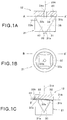
FIG. 1A is a side view of a cyclone body of a collection section according to a first embodiment of the present invention; -
FIG. 1B is a bottom view of a lid as viewed from line A-A' ofFIG. 1A ; -
FIG. 1C is a cross-sectional view on line B-B' ofFIG. 1B , showing the cyclone body; -
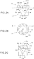
FIG. 2A is a side view of a cyclone body of a collection section according to a second embodiment of the present invention; -
FIG. 2B is a bottom view of a lid as viewed from line A-A' ofFIG. 2A ; -
FIG. 2C is a cross-sectional view on line B-B' ofFIG. 2B , showing the cyclone body; -
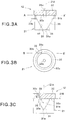
FIG. 3A is a side view of a cyclone body of a collection section according to a third embodiment of the present invention; -
FIG. 3B is a bottom view of a lid as viewed from line A-A' ofFIG. 3A ; -
FIG. 3C is a cross-sectional view on line B-B' ofFIG. 3B , showing the cyclone body; -
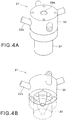
FIG. 4A is a perspective view of a cyclone body; -
FIG. 4B is a perspective view of the cyclone body as viewed from an angle different from that ofFIG. 4A ; -
FIG. 5 is a schematic view showing the overall construction of a measuring apparatus incorporating a cyclone collector according to the present invention; -
FIG. 6(a) is a schematic diagram illustrating a detection target particle to which a fluorescent substance is bonded, andFIG. 6(b) is a schematic diagram illustrating a detection target particle to which an agglomerated antibody particle is bonded; -
FIG. 7 is a schematic view showing a variation of the construction of a droplet forming section of the measuring apparatus; -
FIG. 8 is a perspective view showing the construction of a droplet sorting section of the measuring apparatus; -
FIG. 9 is a diagram showing the internal construction of a measuring section of the measuring apparatus; -
FIG. 10 is a side view of a cyclone body of a collection section according to a fourth embodiment of the present invention; and -
FIG. 11 is a side view of a cyclone body of a collection section according to a fifth embodiment of the present invention. - A first embodiment of the present invention will now be described in detail. The below-described embodiments should not be construed to limit the scope of the invention disclosed herein. Further, the embodiments may be appropriately combined as long as it does not create a contradiction.
- A
cyclone body 21 of acyclone collector 12 according to the present invention consists of a rotating body having an axis of rotation (also referred to as an axis) 21A. As used herein, the terms "upward", "upper end", "downward" and "lower end" refer to "upward", "upper end", "downward " and "lower end" in the case where thecyclone body 21 of thecyclone collector 12 according to the present invention is installed such that the axis ofrotation 21A extends in the vertical and longitudinal direction (seeFIGS. 1A through 1C ). - At the outset, the
entire measuring apparatus 10, in which thecyclone collector 12 according to the present invention is incorporated, will be described with reference toFIGS. 5 through 9 . -
FIG. 5 is a schematic view showing the overall construction of the measuring apparatus.FIG. 5 illustrates a case in which the measuringapparatus 10 detects detection target particles based on the fluorescence intensities of droplets. However, the present invention is not limited to such a case. For example, the measuringapparatus 10 may only perform measurement of the fluorescence intensities of droplets. In that case, based on the fluorescence intensities measured by the measuringapparatus 10, the user or another apparatus will determine whether detection target particles are contained in an analyte gas. The detection target particles are, for example, virus particles, bacteria particles, pollen particles, particles of a toxic substance, etc.; however, the detection target particles are not limited to these as long as a fluorescent substance can specifically bind to the target particles. - As shown in
FIG. 5 , in this embodiment the measuringapparatus 10 includes adust removal section 11, amain pipe 18, a collection section (also referred to as a cyclone collector) 12 according to the present invention, adroplet forming section 13, adroplet sorting section 14, a measuringsection 15, aliquid recovery section 16, and asuction pump 17. - Next, a positional relationship between the components will be described briefly. The
main pipe 18 is a guide passage for a gas flow. Thedust removal section 11 is disposed upstream in a gas flow which is guided by themain pipe 18. Thesuction pump 17 is a gas flow forming mechanism for forming a gas flow in themain pipe 18, and is disposed downstream in the gas flow which is guided by themain pipe 18. In other words, thesuction pump 17 is configured to form a gas flow that flows from thedust removal section 11 to thesuction pump 17 in themain pipe 18. It is also possible to provide, as a gas flow forming mechanism, a gas feed pump upstream of thedust removal section 11. In that case, compressed air may be supplied from the gas feed pump into themain pipe 18. - The
droplet forming section 13, thedroplet sorting section 14, the measuringsection 15 and theliquid recovery section 16 are provided in this order between thedust removal section 11 and thesuction pump 17 in themain pipe 18. - Next, the construction of each component will be described. The
dust removal section 11 has a degree of gas flow resistance which is necessary to form aerosol droplets in themain pipe 18. Thedust removal section 11 is configured to be capable of supplying a clean gas by capturing particles that affect the measurement. - The
collection section 12 consisting of a cyclone collector will now be described. Thecollection section 12 is configured to collect, in a liquid, detection target particles contained in an analyte gas, and to cause a fluorescent substance, which specifically binds to the detection target particles, to bind to the detection target particles in the liquid. - In this embodiment, as shown in
FIG. 5 , thecollection section 12 includes a cyclone body (also referred to as a container) 21, agas introduction section 22 for introducing a gas into thecyclone body 21, and aliquid introduction section 23 for introducing a liquid into thecyclone body 21. - The
cyclone body 21 has a truncated cone-shaped interior surface (hereinafter referred to as a wall surface), and is oriented such that the small-diameter end is located below the large-diameter end. - The
gas introduction section 22 is provided on an upper portion of thecyclone body 21 such that it extends in a direction tangent to the wall surface of thecyclone body 21, and is airtightly coupled to a coarsedust removal section 19. The direction tangent to the wall surface herein refers to a direction tangent to a circle which is defined when thecyclone body 21 is cut off in a horizontal direction, which is perpendicular to the axis of thecyclone body 21, in a portion where a gas, introduced in the below-described manner, hits (collides against) the wall surface of thecyclone body 21. The coarsedust removal section 19 is configured to collect relatively large particles, such as dust and fibers, while allowing passage of analyte particles. The gas, which has been introduced from the coarsedust removal section 19 into thecyclone body 21 through thegas introduction section 22, is guided along the wall surface of thecyclone body 21 so that the gas swirls in the circumferential direction. - The
liquid introduction section 23 includes a tank 23a for storing a liquid, aliquid introduction pipe 23b which, at its one end, is connected to the bottom of the tank 23a and, at the other end, is connected to the wall surface of thecyclone body 21, and a flowrate control section 23c provided in theliquid introduction pipe 23b. - In this embodiment, the tank 23a stores a liquid containing a fluorescent substance. The fluorescent substance is, for example, a fluorescence-labeled antibody. As shown in
FIG. 6(a) , a fluorescence-labeled antibody Y uses an antibody-antigen reaction to specifically bind to a particular detection target particle P. - As shown in
FIG. 6(b) , the fluorescent substance may take the form of an agglomerated antibody particle A whose surface is modified with a plurality of fluorescence-labeled antibodies Y. In this case, the fluorescence-labeled antibodies Y in the surface of the antibody particle A each use an antibody-antigen reaction to specifically bind to a particular detection target particle P. Thus, a plurality of detection target particles P can be agglomerated via the agglomerated antibody particle A. This makes it possible to increase the volume density of fluorescence-labeled antibodies Y, thereby enhancing the fluorescence intensity. - The above-mentioned other end of the
liquid introduction pipe 23b is connected to the wall surface of thecyclone body 21 at a position lower than thegas introduction section 22. On the other hand, the above-mentioned one end of theliquid introduction pipe 23b is disposed at a position higher than the above-mentioned other end. When the flowrate control section 23c is opened, the liquid stored in the tank 23a is allowed by gravity to flow through theliquid introduction pipe 23b into thecyclone body 21. - The
liquid introduction section 23 is not limited to such a construction. For example, theliquid introduction section 23 may include a syringe pump storing a liquid containing a fluorescent substance. The front end of the syringe is coupled to the wall surface of thecyclone body 21 so that when the interior of the syringe is pressurized by a piston, the fluorescent substance-containing liquid is introduced into thecyclone body 21. - In this embodiment, above the
cyclone body 21 is provided a suction/exhaust section 24 for exhausting by suction and thereby depressurizing the interior of thecyclone body 21 so that by the differential pressure, a gas will be introduced from thegas introduction section 22 into thecyclone body 21 in such a manner that the gas swirls in the circumferential direction. - The suction/
exhaust section 24 includes a suction/exhaust pipe (also referred to as an exhaust pipe) 24b concentrically inserted into an upper portion of thecyclone body 21, and a suction/exhaust pump 24a provided for the suction/exhaust pipe 24b. - When the suction/
exhaust pump 24a is actuated, the interior of the suction/exhaust pump 24a is exhausted by suction and depressurized through the suction/exhaust pipe 24b and, by the differential pressure between the inside and the outside of thecyclone body 21, the gas outside thecyclone body 21 is forced through the coarsedust removal section 19 and drawn from thegas introduction section 22 into thecyclone body 21. The gas which has been introduced into thecyclone body 21 is guided along the wall surface of thecyclone body 21, so that the gas descends while swirling in the circumferential direction, i.e. the gas forms a swirling gas flow. Detection target particles in the gas have a relatively high specific gravity, and therefore the detection target particles are separated toward the wall surface of thecyclone body 21 due to centrifugal force. - On the other hand, the gaseous component having a relatively low specific gravity reverses its flow direction at the bottom of the
cyclone body 21 due to the truncated conical shape of thecyclone body 21 and forms an upward flow along the central axis of thecyclone body 21, and is discharged to the outside through the suction/exhaust pipe 24b. - The liquid that has been introduced from the
liquid introduction section 23 into thecyclone body 21 is forced outward by the gas flow swirling in the circumferential direction, and forms a liquid film along the wall surface (interior surface) of thecyclone body 21. Theliquid introduction section 23 thus functions as a liquid-film forming section for forming a liquid film on the interior surface of thecyclone body 21. - In this embodiment, a liquid-
level detector 25 is provided for detecting the level of the liquid formed in the shape of a film on the wall surface of thecyclone body 21. The flowrate control section 23c of theliquid introduction section 23 controls the flow rate of the liquid based on the results of detection by the liquid-level detector 25. - In particular, the liquid-
level detector 25 includes a pair of electrodes exposed in the interior of thecyclone body 21, and a measurement section for measuring the electrical conductivity between the electrodes. When the level of the liquid is higher than the height position of the pair of electrodes, electricity passes between the pair of electrodes through the liquid; thus, the electrical conductivity is relatively high. On the other hand, when the level of the liquid is lower than the height position of the pair of electrodes, the pair of electrodes are insulated from each other; thus, the electrical conductivity is relatively low. An electrical conductivity in the case where the level of the liquid is higher than the height position of the pair of electrodes and an electrical conductivity in the case where the level of the liquid is lower than the height position of the pair of electrodes are experimentally determined in advance, and a value intermediate between the two measurement values is determined as a threshold. When an electrical conductivity, later measured by the measurement section, is higher than the threshold, then the level of the liquid is determined to be higher than the height position of the pair of electrodes. When an electrical conductivity, later measured by the measurement section, is lower than the threshold, then the level of the liquid is determined to be lower than the height position of the pair of electrodes. - When the liquid-
level detector 25 determines that the level of the liquid is lower than the height position of the pair of electrodes, the flowrate control section 23c increases the flow rate of the liquid until the level of the liquid becomes higher than the height position of the pair of electrodes. This can prevent the gas-contact area of the liquid in thecyclone body 21 from decreasing due to discharge or evaporation of the liquid. - A
liquid supply section 26 is connected to the bottom of thecyclone body 21. Theliquid supply section 26 is provided with afeed pump 27. - The
feed pump 27 discharges the liquid from theliquid supply section 26 while applying a pressure to the liquid. Therefore, though the interior of thecyclone body 21 is depressurized by the suction/exhaust section 24, the liquid can be continuously and stably supplied from thecyclone body 21 to thedroplet forming section 13 via theliquid supply section 26. - Though not essential, the
collection section 12 may be equipped with a heating mechanism for heating the liquid. When the reactivity of the fluorescent substance is low in a low temperature environment, e.g. in cold climates, the fluorescent substance in the liquid can be activated and the reaction rate can be increased by heating the liquid up to, for example, around body temperature (about 35 °C). - Alternatively, the
collection section 12 may be equipped with a cooling mechanism (not shown) for cooling the liquid. When the reactivity of the fluorescent substance is low in a high temperature environment, e.g. in extremely hot climates, the fluorescent substance in the liquid can be activated and the reaction rate can be increased by cooling the liquid down to, for example, around body temperature (about 35 °C). - Next, the
droplet forming section 13 will be described. Thedroplet forming section 13 is configured to form aerosol droplets from the liquid supplied from thecollection section 12. In particular, thedroplet forming section 13 is configured to form aerosol droplets from the liquid, supplied from thecollection section 12, by using at least one (two-fluid nozzle) of a nebulizer, an electrospray, a twin-fluid nozzle, a piezoelectric element, ultrasonic waves, and a decompression treatment. - In this embodiment, as shown in
FIG. 5 , thedroplet forming section 13 includes a narrowed portion 18a where the bore of themain pipe 18 is sharply narrowed. The end of theliquid supply section 26 is coaxially inserted into the narrowed portion 18a. The speed of a gas flow, flowing in themain pipe 18, increases when it flows through the narrowed portion 18a. The fast gas flow, flowing through the narrowed portion 18a, creates a negative pressure at the end of theliquid supply section 26. The negative pressure sucks and tears the liquid in theliquid supply section 26, whereby aerosol droplets are formed from the liquid supplied from theliquid supply section 26. - Though in the embodiment illustrated in
FIG. 5 , the end of theliquid supply section 26 is coaxially inserted into the narrowed portion 18a, the present invention is not limited to this feature. For example, as shown inFIG. 7 , the end of theliquid supply section 26 may be orthogonally coupled to the narrowed portion 18a. - Next, the
droplet sorting section 14 will be described. Thedroplet sorting section 14 is configured to sort out droplets having a diameter of less than a predetermined value from the droplets supplied from thedroplet forming section 13. - For example, a spray chamber which uses inertial force to sort out droplets having a diameter of less than a predetermined value can be used as the
droplet sorting section 14. More specifically, the spray chamber may be one selected from the group consisting of a cyclone spray chamber, a Scott-type spray chamber and an inertia branch-type spray chamber. Such spray chambers are known per se in the art of inductively coupled plasma (ICP) emission spectroscopic analysis and described, for example, in JIS K0133. However, this embodiment does not achieve the effect of sorting out droplets, having such a diameter as to be resolvable by inductively coupled plasma, by solely using a spray chamber, but achieves the following effect: As described later, the use of a spray chamber is combined with the technique of using a fluorescent substance which specifically binds to detection target particles. The combination increases the difference between the fluorescence intensity of a droplet containing no detection target particle and the fluorescence intensity of a droplet containing a detection target particle, thereby making it possible to detect target particles with high accuracy. This effect is unexpected from conventionally known spray chambers. -
FIG. 8 is a schematic view showing an example of the construction of thedroplet sorting section 14. Thedroplet sorting section 14 shown inFIG. 8 is a cyclone spray chamber and includes a central chamber body 14a having a cylindrical interior surface, anupper chamber body 14b coupled to the upper end of the central portion and having a truncated conical interior surface, and alower chamber body 14c coupled to the lower end of the central portion and having a truncated conical interior surface. - The
main pipe 18 is connected to the interior surface of the central chamber body 14a such that it extends in a direction tangent to the interior surface. The gas flow containing droplets, which has flown through themain pipe 18 and has been introduced into the central chamber body 14a, is guided along the interior surface of the central chamber body 14a due to inertial force and swirls in the circumferential direction. Droplets having a diameter of not less than the predetermined value are separated toward the interior surface of the central chamber body 14a due to centrifugal force, hitting and adhering to the interior surface. In this manner, droplets having a diameter of not less than the predetermined value are removed from the gas flow, while droplets having a diameter of less than the predetermined value are carried by the gas flow and supplied from the top of theupper chamber body 14b to the measuringsection 15. The droplets (liquid) that have adhered to the interior surface of the central chamber body 14a flow down by gravity into thelower chamber body 14c, and are discharged to the outside from the bottom of thelower chamber body 14c. In cases where only a small amount of droplets (liquid) adhere to the interior surface of the central chamber body 14a, the adhering droplets (liquid) will evaporate. Therefore, there is no need to provide a liquid discharge mechanism. - Since a spray chamber uses inertial force to sort out droplets, the upper limit of the diameters of droplets to be sorted out by the spray chamber is correlated with dynamic parameters such as the size and the shape of the spray chamber, the speed of the gas flow, etc. Accordingly, the upper limit of the diameters of droplets to be sorted out by the spray chamber can be set to a desired value by appropriately selecting dynamic parameters such as the size and the shape of the spray chamber, the speed of the gas flow, etc. While the diameter of droplets to be sorted out by the spray chamber can be appropriately selected depending on the measuring object and the measurement purpose, it is preferably not more than 50 µm, more preferably not more than 20 µm when the measuring object is virus or bacteria.
- Next, the measuring
section 15 will be described.FIG. 9 is a schematic view showing an example of the construction of the measuringsection 15. The measuringsection 15 is configured to irradiate a droplet with light and measure the fluorescence intensity of the droplet. - In this embodiment, as shown in
FIG. 9 , the measuringsection 15 includes acase body 56, e.g. having a rectangular shape, connected to themain pipe 18 and which forms a space that allows passage of a gas flow containing droplets that have been sorted out by thedroplet sorting section 14.Light transmissive windows case body 56 which oppose each other. - Outside one
light transmissive window 52a is provided a light-emittingsection 51 for emitting laser light, having a wavelength which is different from the wavelength of the fluorescence emitted by the fluorescent substance, into thecase body 56. Outside the other lighttransmissive window 52b is provided anoptical filter 53 for blocking the light having a wavelength which is different from the wavelength of the fluorescence emitted by the fluorescent substance. Outside theoptical filter 53 is provided a light-receivingsection 54 for receiving the fluorescence of the fluorescent substance and converting it into an electrical signal. The light-receivingsection 54 is, for example, a photomultiplier tube and configured to output, to a received-lightoutput measuring section 55, for example an electric current of a signal level corresponding to the intensity of the light received from theoptical filter 53. - The received-light
output measuring section 55 is configured to, for example, convert an electric current into a voltage and compare a voltage signal Ia, which indicates the voltage after conversion, with a preset threshold Is and, when the voltage signal Ia is determined to be higher than the threshold Is, issue an alarm indicating detection of detection target particles or display the alarm on a not-shown display. - For the voltage signal Ia which is a signal corresponding to the intensity of the received light, the threshold Is can be determined as follows. The threshold Is is set to an intermediate value between a fluorescence intensity as measured when droplets, formed by the
droplet forming section 13 in the case where no detection target particles are present in the analyte gas, pass through thecase body 56 and a fluorescence intensity as measured when droplets, formed by thedroplet forming section 13 in the case where detection target particles are contained in the analyte gas and the fluorescent substance is bonded to the detection target particles, pass through thecase body 56. The fluorescence intensity, measured when no detection target particles are present in the analyte gas, corresponds to the intensity of fluorescence from the fluorescent substance adhering to dust contained in the gas passing through thecase body 56, or to the intensity of fluorescence from the fluorescent substance contained in droplets containing no detection target particles. The fluorescent substance specifically binds to detection target particles. Therefore, roughly speaking, the density of the fluorescent substance is higher when detection target particles are present. Thus, a difference in the fluorescence intensity exists between the presence and absence of detection target particles. - Returning to
FIG. 5 , theliquid recovery section 16, e.g. comprised of a mesh body, for capturing droplets that have passed through the measuringsection 15 is provided downstream of the measuringsection 15. Thesuction pump 17 is provided downstream of theliquid recovery section 16 so that the gas, which has passed through theliquid recovery section 16, is discharged to the outside of the measuringapparatus 10 via a not-shown filter for removing by adsorption detection target particles. Theliquid recovery section 16 is provided with a liquid discharge mechanism. However, in cases where the amount of droplets (liquid) passing through theliquid recovery section 16 is sufficiently small, the droplets (liquid) will evaporate; therefore, there is no need to provide a liquid discharge mechanism. - The
collection section 12, consisting of the cyclone collector incorporated in the measuringapparatus 10, will now be described with reference toFIGS. 1A through 1C andFIGS. 4A and 4B . -
FIG. 1A is a side view of thecyclone body 21 of thecollection section 12,FIG. 1B is a bottom view of a lid as viewed from line A-A' ofFIG. 1A, and FIG. 1C is a cross-sectional view on line B-B' ofFIG. 1B , showing thecyclone body 21.FIGS. 4A and 4B are each a perspective view of the cyclone body. - As described above, the
collection section 12 includes the cyclone body (also referred to as the container) 21, thegas introduction section 22 for introducing a gas into thecyclone body 21, and the liquid introduction section (also referred to as the liquid-film forming section) 23 for introducing a liquid into thecyclone body 21 and forming aliquid film 40 on the interior surface of thecyclone body 21. - More specifically, as shown in
FIGS. 1A through 1C andFIGS. 4A and 4B , the cyclone body (container) 21 of thecollection section 12 includes acontainer body 31 that internally forms a truncatedconical space 35, and alid 32 that overs the top opening of thecontainer body 31. Theliquid introduction pipe 23b of theliquid introduction section 23 is connected to the side of thecontainer body 31 of thecyclone body 21. Thecyclone body 21 including thecontainer body 31 and thelid 32 is a rotating body having an axis ofrotation 21A, and is disposed such that theaxis 21A extends in the longitudinal direction. Thecyclone body 21 is not limited to the one having the above structure, i.e. including thecontainer body 31, and thelid 32 that covers the top opening of thecontainer body 31. For example, thecyclone body 21 may have a structure in which thecontainer body 31 and thelid 32 are formed completely integrally and which has been obtained by using, for example, a 3D printer. In that case, thelid 32 of thecyclone body 21 constitutes an upper-end portion of thecyclone body 21, and the truncatedconical side wall 31b of thecontainer body 31 constitutes theside wall 31b of thecyclone body 21. Further, the lower-end portion 31a of thecontainer body 31 constitutes the lower-end portion 31a of thecyclone body 21. - The
gas introduction section 22 is coupled to thelid 32 constituting the upper end of thecyclone body 21, and to thegas introduction section 22 is connected aconnection end 33b of agas inlet 33 formed in thelid 32. In this embodiment, fourgas introduction sections 22 are coupled to thelid 32 such that eachgas introduction section 22 extends in a direction tangent to the wall surface of thecyclone body 21. The fourgas introduction sections 22 are disposed at 90-degree intervals around the circumference of thelid 32. Thus, fourgas inlets 33, corresponding to the fourgas introduction sections 22, are provided at 90-degree intervals in thelid 32. The direction tangent to the wall surface herein refers to a direction tangent to a circle which is defined when thecyclone body 21 is cut off in a horizontal direction, which is perpendicular to the axis of thecyclone body 21, in a portion where the gas introduced hits (collides against) the wall surface of thecyclone body 21. In the case of fourgas introduction sections 22, the gases introduced from the four sections preferably hit (collide against) the wall surface of thecyclone body 21 at the same height position. Thus, the fourgas introduction sections 22 preferably extend in directions tangent to the same circle. - An
exhaust pipe 24b is mounted in the center of thelid 32. Theexhaust pipe 24b extends upward from thespace 35 in thecontainer body 31 and penetrates thelid 32. Theliquid supply section 26 is mounted to the lower-end portion 31a of thecontainer body 31 of thecyclone body 21. Theliquid supply section 26 is connected to thedroplet forming section 13 via thefeed pump 27. - The four
gas inlets 33, provided in thelid 32, will now be described. Eachgas inlet 33 extends in thelid 32 downward at an inclination angle θ of 5° to 15° with anorthogonal plane 21B perpendicular to theaxis 21A of thecyclone body 21. Eachgas inlet 33 has anopening 33a that opens into thespace 35 in thecontainer body 31. Theopening 33a opens in the same plane as thelower surface 32a of thelid 32 without projecting downward from thelower surface 32a. - A
liquid film 40, composed of the liquid that has been introduced from theliquid introduction pipe 23b of theliquid introduction section 23, is formed on the interior surface of thecyclone body 21. Theliquid film 40 is formed over an area from the lower end to the upper end of thecontainer body 31, in particular an area from the lower-end portion 31a of thecontainer body 31 to a position on theside wall 31b just below thelid 32. Theliquid film 40 does not reach thelower surface 32a of thelid 32. - The
openings 33a of thegas inlets 33 provided in thelid 32 each open in thelower surface 32a of thelid 32 at a position at a distance from the side wall of thecontainer body 31. Therefore, theliquid film 40 on the interior surface of thecontainer body 31 will not be caught in the intake gas from theopenings 33a of thegas inlets 33. This prevents the generation of a mist caused by the liquid film being caught in the intake gas. - On the other hand, since the
gas inlets 33 extend downward at an angle with theorthogonal plane 21B of thecyclone body 21, the intake gas ejected from eachgas inlet 33 hits theliquid film 40 formed on the interior surface of thecontainer body 31 and located at a position facing theopening 33a. This enables particles, contained in the intake gas, to securely adhere to theliquid film 40, thus allowing theliquid film 40 to securely collect the particles. - If the intake gas ejected from each
gas inlet 33 does not hit theliquid film 40 in thecontainer body 31, then it may not be possible to cause particles in the intake gas to adhere to theliquid film 40. The particles may be forced to fly upward in thecontainer body 31 and discharged from theexhaust pipe 24b. - In contrast, according to the present invention, the intake gas, ejected from each
gas inlet 33 into thecyclone body 21, is ejected along a direction tangent to the wall surface of thecyclone body 21 in a portion where the gas hits the liquid film, and creates a gas flow that swirls in the circumferential direction of thecyclone body 21. Therefore, particles in the intake gas move toward theside wall 31b of thecontainer body 31 due to centrifugal force. The particles in the intake gas ejected from thegas inlets 33 are thus allowed to securely hit and adhere to theliquid film 40, and then can be collected. - The operation of the thus-constructed measuring apparatus according to this embodiment will now be described.
- First, as shown in
FIG. 5 , a gas (e.g. air) is drawn by thesuction pump 17 into themain pipe 18 via thedust removal section 11, and a gas flow is created which flows through thedroplet forming section 13, thedroplet sorting section 14, the measuringsection 15 and theliquid recovery section 16 in this order, and which is discharged via thesuction pump 17 and the not-shown filter. - On the other hand, by the operation of the suction/
exhaust pump 24a of thecollection section 12, a gas (e.g. air) is drawn into thegas introduction sections 22 of thecollection section 12 via the coarsedust removal section 19, and introduced from thegas introduction sections 22 into thecyclone body 21. Further, a liquid containing a fluorescent substance is introduced from theliquid introduction section 23 into thecyclone body 21. - The gas, which has been introduced from the
gas introduction sections 22 into thecyclone body 21, is guided along the wall surface of thecyclone body 21, so that the gas swirls in the circumferential direction and creates a spiral flow in thecyclone body 21. The liquid, which has been introduced from theliquid introduction section 23 into thecyclone body 21, is forced radially outward by the spiral gas flow and forms into a film along the wall surface of thecyclone body 21. - Detection target particles contained in the gas are separated toward the wall surface of the
cyclone body 21 due to centrifugal force, and collected in the film-shaped liquid. The fluorescent substance contained in the liquid specifically binds to the collected detection target particles. - The behavior of the gas in the
cyclone body 21 will now be described with reference toFIGS. 1A through 1C . - As shown in
FIGS. 1A through 1C , the intake gas, which has been introduced from thegas introduction sections 22, passes through thegas inlets 33 provided in thelid 32 and is ejected from theopenings 33a of thegas inlets 33 into thespace 35 in thecontainer body 31. - The
openings 33a of thegas inlets 33 are located at a distance from theside wall 31b of thecontainer body 31 where theliquid film 40 is formed. Therefore, it is unlikely that the liquid film, formed on the interior surface of thecontainer body 31, will be caught in the intake gas, resulting in the generation of a mist. - The intake gas, ejected from the
openings 33a of thegas inlets 33, hits theliquid film 40 formed on the interior surface of thecontainer body 31. This enables particles in the intake gas to securely adhere to and be collected in theliquid film 40. - The liquid in which detection target particles are collected on the wall surface of the
cyclone body 21 gradually flows downward by gravity and, by the operation of thefeed pump 27, is continuously supplied from the bottom of thecyclone body 21 to thedroplet forming section 13 via theliquid supply section 26. - In the
droplet forming section 13, the liquid supplied from thecollection section 12 is drawn from the end of theliquid supply section 26 by the fast gas flow flowing through the narrowed portion 18a of themain pipe 18, and is formed into aerosol droplets. The aerosol droplets are carried by the gas flow in themain pipe 18 to thedroplet sorting section 14. - As shown in
FIG. 8 , in thedroplet sorting section 14, the gas flow containing the droplets supplied from thedroplet forming section 13 is guided along the cylindrical interior surface of the central chamber body 14a, whereby it swirls in the circumferential direction. Droplets having a diameter of not less than a predetermined value, contained in the gas flow, are separated toward the interior surface of the central chamber body 14a due to centrifugal force, and hit and adhere to the interior surface. On the other hand, droplets having a diameter of less than the predetermined value move upward while swirling in the circumferential direction together with the gas flow, and are supplied from the top of theupper chamber body 14b to the measuringsection 15. - As shown in
FIG. 9 , the measuringsection 15 irradiates droplets, which have been sorted out by thedroplet sorting section 14, with light and measures the fluorescence intensities of the irradiated droplets. In particular, the measuringsection 15 irradiates droplets, which have been guided by themain pipe 18, with light and measures the fluorescence intensities of the irradiated droplets. Thereafter, the measuringsection 15, for example, determines whether detection target particles are contained in the analyte gas by comparing the measured fluorescence intensities with a threshold. In other words, the measuringsection 15 detects detection target particles in the analyte gas. - For example, in the measuring
section 15, the light-emittingsection 51 emits ultraviolet laser light into thecase body 56 through which droplets are flowing. A fluorescent substance in a droplet is excited by the ultraviolet laser light and emits fluorescence. The ultraviolet laser light is then blocked by theoptical filter 53, and light having a fluorescence wavelength is selectively detected by the light-receivingsection 54. The intensity of received light, detected by the light-receivingsection 54, is proportional to the volume density of the fluorescent substance in a droplet formed by thedroplet forming section 13. - In the case where detection target particles are present in droplets formed by the
droplet forming section 13, the fluorescence intensities detected by the light-receivingsection 54 are higher than the threshold Is, and the received-lightoutput measuring section 55 issues an alarm indicating detection of detection target particles. - In the case where no detection target particles are present in droplets formed by the
droplet forming section 13, even when fine dust in the air is incorporated into the droplets and the fluorescent substance adheres to the dust, the density of the fluorescent substance is much lower than the density of the fluorescent substance bonded to detection target particles. Accordingly, the intensity of received light detected by the light-receivingsection 54 is lower than the preset threshold Is. - The gas flow containing droplets, which has passed through the measuring
section 15, is separated into the gas and the liquid, and the liquid is recovered. The gas, on the other hand, is discharged to the outside of the measuringapparatus 10 by thesuction pump 17 provided downstream of theliquid recovery section 16. - A
collection section 12 consisting of a cyclone collector according to a second embodiment will now be described with reference toFIGS. 2A through 2C . - In the second embodiment shown in
FIGS. 2A through 2C , the same symbols are used for the same components or elements as those of the first embodiment shown inFIGS. 1A through 1C ,FIGS. 4A and 4B , andFIGS. 5 through 9 , and a detailed description thereof is omitted. -
FIG. 2A is a side view of thecyclone body 21 of thecollection section 12,FIG. 2B is a bottom view of a lid as viewed from line A-A' ofFIG. 2A, and FIG. 2C is a cross-sectional view on line B-B' ofFIG. 2B , showing thecyclone body 21. - As described above, the
collection section 12 includes a cyclone body (also referred to as a container) 21, agas introduction section 22 for introducing a gas into thecyclone body 21, and a liquid introduction section (also referred to as a liquid-film forming section) 23 for introducing a liquid into thecyclone body 21 and forming aliquid film 40 on the interior surface of thecyclone body 21. - More specifically, as shown in
FIGS. 2A through 2C , the cyclone body (container) 21 of thecollection section 12 includes acontainer body 31 that internally forms a truncatedconical space 35, and alid 32 that overs the top opening of thecontainer body 31. Theliquid introduction pipe 23b of theliquid introduction section 23 is connected to the side of thecontainer body 31 of thecyclone body 21. - The
gas introduction section 22 is coupled to thelid 32 of thecyclone body 21, and to thegas introduction section 22 is connected aconnection end 33b of agas inlet 33 formed in thelid 32. In this embodiment, eightgas introduction sections 22 are coupled to thelid 32 such that eachgas introduction section 22 extends in a direction tangent to the wall surface of thecyclone body 21. The eightgas introduction sections 22 are disposed at 45-degree intervals around the circumference of thelid 32. Thus, eightgas inlets 33, corresponding to the eightgas introduction sections 22, are provided at 45-degree intervals in thelid 32. - An
exhaust pipe 24b is mounted in thelid 32. Theexhaust pipe 24b extends upward from thespace 35 in thecontainer body 31 and penetrates thelid 32. - The eight
gas inlets 33, provided in thelid 32, will now be described. Eachgas inlet 33 extends in thelid 32 downward at an inclination angle θ of 45° to 60° with anorthogonal plane 21B perpendicular to theaxis 21A of thecyclone body 21. Eachgas inlet 33 has anopening 33a that opens into thespace 35 in thecontainer body 31. Theopening 33a opens in the same plane as thelower surface 32a of thelid 32 without projecting downward from thelower surface 32a. - A
liquid film 40, composed of the liquid that has been introduced from theliquid introduction pipe 23b of theliquid introduction section 23, is formed on the interior surface of thecyclone body 21. Theliquid film 40 is formed over an area from the lower end to the upper end of thecontainer body 31, in particular an area from the lower-end portion 31a of thecontainer body 31 to a position on theside wall 31b just below thelid 32. Theliquid film 40 does not reach thelower surface 32a of thelid 32. - The
openings 33a of thegas inlets 33 provided in thelid 32 each open in thelower surface 32a of thelid 32 at a position at a distance from the interior surface of thecontainer body 31. Therefore, theliquid film 40 on the interior surface of thecontainer body 31 will not be caught in the intake gas from theopenings 33a of thegas inlets 33. This prevents the generation of a mist caused by the liquid film being caught in the intake gas. - On the other hand, since the
gas inlets 33 extend downward at an angle with theorthogonal plane 21B of thecyclone body 21, the intake gas ejected from eachgas inlet 33 hits theliquid film 40 formed on the interior surface of thecontainer body 31 and located at a position facing theopening 33a. This enables particles, contained in the intake gas, to securely adhere to theliquid film 40, thus allowing theliquid film 40 to securely capture the particles. - If the intake gas ejected from each
gas inlet 33 does not hit theliquid film 40 in thecontainer body 31, then it may not be possible to cause particles in the intake gas to adhere to theliquid film 40. The particles may be forced to fly upward in thecontainer body 31 and discharged from theexhaust pipe 24b. - In contrast, according to the present invention, the intake gas ejected from the
gas inlets 33 is allowed to hit theliquid film 40. This makes it possible to cause particles in the intake gas to adhere to theliquid film 40, and to securely collect the particles in the liquid. According to this embodiment, the number of thegas inlets 33 is increased by increasing the angle θ of eachgas inlet 33. This can increase the amount of gas that can be treated at a time. However, the gas flow hits the wall surface at a lower position. - A
collection section 12 consisting of a cyclone collector according to a third embodiment will now be described with reference toFIGS. 3A through 3C . - In the third embodiment shown in
FIGS. 3A through 3C , the same symbols are used for the same components or elements as those of the first embodiment shown inFIGS. 1A through 1C ,FIGS. 4A and 4B , andFIGS. 5 through 9 , and a detailed description thereof is omitted. -
FIG. 3A is a side view of thecyclone body 21 of thecollection section 12,FIG. 3B is a bottom view of a lid as viewed from line A-A' ofFIG. 3A, and FIG. 3C is a cross-sectional view on line B-B' ofFIG. 3B , showing thecyclone body 21. - As described above, the
collection section 12 includes a cyclone body (also referred to as a container) 21, agas introduction section 22 for introducing a gas into thecyclone body 21, and a liquid introduction section (also referred to as a liquid-film forming section) 23 for introducing a liquid into thecyclone body 21 and forming aliquid film 40 on the interior surface of thecyclone body 21. - More specifically, as shown in
FIGS. 3A through 3C , the cyclone body (container) 21 of thecollection section 12 includes acontainer body 31 that internally forms a truncatedconical space 35, and alid 32 that overs the top opening of thecontainer body 31. Theliquid introduction pipe 23b of theliquid introduction section 23 is connected to the side of thecontainer body 31 of thecyclone body 21. - The
gas introduction section 22 is coupled to thelid 32 of thecyclone body 21, and to thegas introduction section 22 is connected aconnection end 33b of agas inlet 33 formed in thelid 32. In this embodiment, a singlegas introduction section 22 is coupled to thelid 32. However, it is also possible to provide a plurality ofgas introduction section 22,gas inlets 33 and projectingnozzles 36. - An
exhaust pipe 24b is mounted in thelid 32. Theexhaust pipe 24b extends upward from thespace 35 in thecontainer body 31 and penetrates thelid 32. - The
gas inlet 33, provided in thelid 32, will now be described. Thegas inlet 33 extends in thelid 32 downward at an inclination angle θ of 45° to 60° with anorthogonal plane 21B perpendicular to theaxis 21A of thecyclone body 21. Thegas inlet 33 has a projectingnozzle 36 which projects from thelower surface 32a of thelid 32 into thespace 35 in thecontainer body 31 and which opens at the lower end, forming anopening 33a. Thus, theopening 33a is located at the lower end of the projectingnozzle 36 projecting downward from thelower surface 32a of thelid 32. - A
liquid film 40, composed of the liquid that has been introduced from theliquid introduction pipe 23b of theliquid introduction section 23, is formed on the interior surface of thecyclone body 21. Theliquid film 40 is formed over an area from the lower end to the upper end of thecontainer body 31, i.e. an area from the lower end of thecontainer body 31 to thelower surface 32a of thelid 32. - The
opening 33a of thegas inlet 33 provided in thelid 32 is located at the lower end of the projectingnozzle 36 projecting from thelower surface 32a of thelid 32, and opens at a position at a distance from the interior surface of thecontainer body 31. Therefore, theliquid film 40 on the interior surface of thecontainer body 31 will not be caught in the intake gas from theopening 33a of thegas inlet 33. This prevents the generation of a mist caused by the liquid film being caught in the intake gas. - On the other hand, since the
gas inlet 33 extends downward at an angle with theorthogonal plane 21B of thecyclone body 21, the intake gas ejected from thegas inlet 33 hits theliquid film 40 formed on the interior surface of thecontainer body 31 and located at a position facing theopening 33a. This enables particles, contained in the intake gas, to securely adhere to theliquid film 40, thus allowing theliquid film 40 to securely capture the particles. - If the intake gas ejected from the
gas inlet 33 does not hit theliquid film 40 in thecontainer body 31, then it may not be possible to cause particles in the intake gas to adhere to theliquid film 40. The particles may be forced to fly upward in thecontainer body 31 and discharged from theexhaust pipe 24b. - In contrast, according to the present invention, the intake gas ejected from the
gas inlet 33 is allowed to hit theliquid film 40. This makes it possible to cause particles in the intake gas to adhere to theliquid film 40, and to securely collect the particles in the liquid. - A
collection section 12 consisting of a cyclone collector according to a fourth embodiment will now be described with reference toFIG. 10 . - In the fourth embodiment shown in
FIG. 10 , the same symbols are used for the same components or elements as those of the first embodiment shown inFIGS. 1A through 1C ,FIGS. 4A and 4B , andFIGS. 5 through 9 , and a detailed description thereof is omitted. -
FIG. 10 is a side view of thecyclone body 21 of thecollection section 12. - As described above, the
collection section 12 includes a cyclone body (also referred to as a container) 21, agas introduction section 22 for introducing a gas into thecyclone body 21, and a liquid introduction section (also referred to as a liquid-film forming section) 23 for introducing a liquid into thecyclone body 21 and forming aliquid film 40 on the interior surface of thecyclone body 21. - More specifically, as shown in
FIG. 10 , the cyclone body (container) 21 of thecollection section 12 includes acontainer body 31 which internally forms a truncatedconical space 35 and which consist of a rotating body having an axis ofrotation 21A. Theconical body 35 is hermetically sealed as a whole and includes a lower-end portion 31a, an upper-end portion 31c and aside wall 31b extending between the lower-end portion 31a and the top-end portion 31c. Theliquid introduction pipe 23b of theliquid introduction section 23 is connected to theside wall 31b. - The
gas introduction section 22 is coupled to the upper-end portion 31c of thecontainer body 31 of thecyclone body 21, and to thegas introduction section 22 is connected aconnection end 33b of agas inlet 33 formed in the upper-end portion 31c. In this embodiment, fourgas introduction sections 22 are coupled to the upper-end portion 31c such that eachgas introduction section 22 extends in a direction tangent to the wall surface of thecyclone body 21. The fourgas introduction sections 22 are disposed at 90-degree intervals around the circumference of the upper-end portion 31c. Thus, fourgas inlets 33, corresponding to the fourgas introduction sections 22, are provided at 90-degree intervals in the upper-end portion 31c. - An
exhaust pipe 24b is mounted in the center of the upper-end portion 31c. Theexhaust pipe 24b extends upward from thespace 35 in thecontainer body 31 and penetrates the upper-end portion 31c. Theliquid supply section 26 is mounted to theside wall 31b of thecontainer body 31 of thecyclone body 21. Theliquid supply section 26 is connected to thedroplet forming section 13 via the feed pump 27 (seeFIG. 5 ). Aninlet 26a, which is inversely tapered toward thespace 35, is formed at the entrance to theliquid supply section 26 mounted to theside wall 31b. Since theliquid supply section 26 is mounted to theside wall 31b in this embodiment, the liquid, which has a higher specific gravity than air, can be smoothly brought by centrifugal force from the inversely taperedinlet 26a to theliquid supply section 26. - The four
gas inlets 33, provided in the upper-end portion 31c of thecontainer body 31, will now be described. Eachgas inlet 33 extends in the upper-end portion 31c downward at an inclination angle θ of 5° to 15° with anorthogonal plane 21B perpendicular to theaxis 21A of thecyclone body 21. Eachgas inlet 33 has anopening 33a that opens into thespace 35 in thecontainer body 31. Theopening 33a opens in the same plane as the lower surface 31c1 of the upper-end portion 31c without projecting downward from the lower surface 31c1. - A
liquid film 40, composed of the liquid that has been introduced from theliquid introduction pipe 23b of theliquid introduction section 23, is formed on the interior surface of theside wall 31b of thecyclone body 21. Theliquid film 40 is formed over an area from the lower end to the upper end of theside wall 31b of thecontainer body 31. However, theliquid film 40 does not reach the lower surface 31c1 of the upper-end portion 31c. - The
openings 33a of thegas inlets 33 provided in the upper-end portion 31c of thecontainer body 31 each open in the lower surface 31c1 of the upper-end portion 31c at a position at a distance from theside wall 31b of thecontainer body 31. Therefore, theliquid film 40 on the interior surface of theside wall 31b of thecontainer body 31 will not be caught in the intake gas from theopenings 33a of thegas inlets 33. This prevents the generation of a mist caused by the liquid film being caught in the intake gas. - On the other hand, since the
gas inlets 33 extend obliquely downward with respect to theorthogonal plane 21B of thecyclone body 21, the intake gas ejected from eachgas inlet 33 hits theliquid film 40 formed on the interior surface of theside wall 31b of thecontainer body 31 and located at a position facing theopening 33a. Therefore, particles contained in the intake gas move to theliquid film 40 due to centrifugal force. This enables the particles to securely adhere to theliquid film 40, thus allowing theliquid film 40 to securely collect the particles. - If the intake gas ejected from each
gas inlet 33 does not hit theliquid film 40 on the interior surface of theside wall 31b of thecontainer body 31, then it may not be possible to cause particles in the intake gas to adhere to theliquid film 40. The particles may be forced to fly upward in thecontainer body 31 and discharged from theexhaust pipe 24b. - In contrast, according to the present invention, the intake gas ejected from the
gas inlets 33 is allowed to hit theliquid film 40. This makes it possible to cause particles in the intake gas to adhere to theliquid film 40, and to securely collect the particles in the liquid. Thecyclone body 21 shown inFIG. 10 may be used in a vertically inverted shape: the upper-end portion 31c and the lower-end portion 31a are interchanged, and thegas introduction sections 22 and theexhaust pipe 24b are disposed at lower positions. - A
collection section 12 consisting of a cyclone collector according to a fifth embodiment will now be described with reference toFIG. 11 . - In the fifth embodiment shown in
FIG. 11 , the same symbols are used for the same components or elements as those of the first embodiment shown inFIGS. 1A through 1C ,FIGS. 4A and 4B , andFIGS. 5 through 9 , and a detailed description thereof is omitted. -
FIG. 11 is a side view of thecyclone body 21 of thecollection section 12. - As described above, the
collection section 12 includes a cyclone body (also referred to as a container) 21, agas introduction section 22 for introducing a gas into thecyclone body 21, and a liquid introduction section (also referred to as a liquid-film forming section) 23 for introducing a liquid into thecyclone body 21 and forming aliquid film 40 on the interior surface of thecyclone body 21. - More specifically, as shown in
FIG. 11 , the cyclone body (container) 21 of thecollection section 12 includes acontainer body 31 which internally forms a truncatedconical space 35 and which consist of a rotating body having an axis ofrotation 21A. Theconical body 35 is hermetically sealed as a whole and includes a lower-end portion 31a, an upper-end portion 31c and aside wall 31b extending between the lower-end portion 31a and the top-end portion 31c. Theliquid introduction pipe 23b of theliquid introduction section 23 is connected to theside wall 31b. - The
gas introduction section 22 is coupled to the upper-end portion 31c of thecontainer body 31 of thecyclone body 21, and to thegas introduction section 22 is connected aconnection end 33b of agas inlet 33 formed in the upper-end portion 31c. In this embodiment, fourgas introduction sections 22 are coupled to the upper-end portion 31c such that eachgas introduction section 22 extends in a direction tangent to the wall surface of thecyclone body 21. The fourgas introduction sections 22 are disposed at 45-degree intervals around the circumference of the upper-end portion 31c. Thus, fourgas inlets 33, corresponding to the fourgas introduction sections 22, are provided at 90-degree intervals in the upper-end portion 31c. - An
exhaust pipe 24b is mounted in the center of the lower-end portion 31a. Theexhaust pipe 24b extends downward from thespace 35 in thecontainer body 31 and penetrates the lower-end portion 31a. Since theexhaust pipe 24b is mounted in the center of the lower-end portion 31a, theexhaust pipe 24b is located opposite thegas introduction sections 22 in the upper-end portion 31c. This can increase the degree of freedom of the installation position of thegas introduction sections 22 in the upper-end portion 31c. Theliquid supply section 26 is mounted to theside wall 31b of thecontainer body 31 of thecyclone body 21. Theliquid supply section 26 is connected to thedroplet forming section 13 via the feed pump 27 (seeFIG. 5 ). Aninlet 26a, which is inversely tapered toward thespace 35, is formed at the entrance to theliquid supply section 26 mounted to theside wall 31b. Since theliquid supply section 26 is mounted to theside wall 31b in this embodiment, the liquid having a high specific gravity can be smoothly brought by centrifugal force from the inversely taperedinlet 26a to theliquid supply section 26. - The four
gas inlets 33, provided in the upper-end portion 31c of thecontainer body 31, will now be described. Eachgas inlet 33 extends in the upper-end portion 31c downward at an inclination angle θ of 5° to 15° with anorthogonal plane 21B perpendicular to theaxis 21A of thecyclone body 21. Eachgas inlet 33 has anopening 33a that opens into thespace 35 in thecontainer body 31. Theopening 33a opens in the same plane as the lower surface 31c1 of the upper-end portion 31c without projecting downward from the lower surface 31c1. - A
liquid film 40, composed of the liquid that has been introduced from theliquid introduction pipe 23b of theliquid introduction section 23, is formed on the interior surface of theside wall 31b of thecyclone body 21. Theliquid film 40 is formed over an area from the lower end to the upper end of theside wall 31b of thecontainer body 31. However, theliquid film 40 does not reach the lower surface 31c1 of the upper-end portion 31c. - The
openings 33a of thegas inlets 33 provided in the upper-end portion 31c of thecontainer body 31 each open in the lower surface 31c1 of the upper-end portion 31c at a position at a distance from theside wall 31b of thecontainer body 31. Therefore, theliquid film 40 on the interior surface of theside wall 31b of thecontainer body 31 will not be caught in the intake gas from theopenings 33a of thegas inlets 33. This prevents the generation of a mist caused by the liquid film being caught in the intake gas. - On the other hand, since the
gas inlets 33 extend obliquely downward with respect to theorthogonal plane 21B of thecyclone body 21, the intake gas ejected from eachgas inlet 33 hits theliquid film 40 formed on the interior surface of theside wall 31b of thecontainer body 31 and located at a position facing theopening 33a. Therefore, particles contained in the intake gas move to theliquid film 40 due to centrifugal force. This enables the particles to securely adhere to theliquid film 40, thus allowing theliquid film 40 to securely collect the particles. - If the intake gas ejected from each
gas inlet 33 does not hit theliquid film 40 on the interior surface of theside wall 31b of thecontainer body 31, then it may not be possible to cause particles in the intake gas to adhere to theliquid film 40. The particles may be forced to fly upward in thecontainer body 31 and discharged from theexhaust pipe 24b. - In contrast, according to the present invention, the intake gas ejected from the
gas inlets 33 is allowed to hit theliquid film 40. This makes it possible to cause particles in the intake gas to adhere to theliquid film 40, and to securely collect the particles in the liquid. -
- 10 measuring apparatus
- 11 dust removal section
- 12 collection section
- 13 droplet forming section
- 14 droplet sorting section
- 15 measuring section
- 16 liquid recovery section
- 17 suction pump
- 18 main pipe
- 18a narrowed portion
- 19 coarse dust removal section
- 21 cyclone body
- 21A axis
- 21B orthogonal plane
- 22 gas introduction section
- 23 liquid introduction section
- 23a tank
- 23b liquid introduction pipe
- 31 container body
- 31a lower-end portion
- 31b side wall
- 31c upper-end portion
- 32 lid
- 32a lower surface
- 33 gas inlet
- 33a opening
- 33b connection end
- 35 space
- 36 projecting nozzle
- 40 liquid film
Claims (8)
- A cyclone collector, comprising:a container which internally forms a space and which consists of a rotating body having an axis of rotation, and including an upper-end portion, a lower-end portion, and a side wall extending between the upper-end portion and the lower-end portion;a liquid-film forming section, provided for the container, for forming a liquid film having a certain height on an interior surface of the side wall,a gas inlet provided in the container and having an opening that opens in the container; andan exhaust pipe provided in the container,wherein the gas inlet extends toward the space at an angle with an orthogonal plane perpendicular to the axis of rotation of the container, and wherein the entire area of the opening of the gas inlet is located outside an area where the liquid film exists, and an intake gas is ejected from the gas inlet toward the liquid film.
- The cyclone collector according to claim 1, wherein the gas inlet is provided in the upper-end portion of the container.
- The cyclone collector according to claim 1 or 2, wherein the liquid-film forming section forms the liquid film on the interior surface of the side wall such that it extends upward from the lower-end portion of the container.
- The cyclone collector according to any one of claims 1 to 3, wherein the gas inlet is provided in plural numbers.
- The cyclone collector according to any one of claims 2 to 4, wherein the gas inlet is provided in the upper-end portion of the container, and the opening opens into the space in the container.
- The cyclone collector according to any one of claims 2 to 4, wherein the gas inlet is provided in the upper-end portion of the container, and has a projecting nozzle which projects from the surface of the upper-end portion and which, at its front end, has said opening.
- The cyclone collector according to any one of claims 1 to 6, wherein a liquid supply section is mounted to the lower-end portion of the container.
- The cyclone collector according to any one of claims 1 to 6, wherein a liquid supply section is mounted to the side wall of the container.
Applications Claiming Priority (2)
| Application Number | Priority Date | Filing Date | Title |
|---|---|---|---|
| JP2017108770 | 2017-05-31 | ||
| PCT/JP2018/002617 WO2018220896A1 (en) | 2017-05-31 | 2018-01-29 | Cyclone collector |
Publications (3)
| Publication Number | Publication Date |
|---|---|
| EP3632571A1 true EP3632571A1 (en) | 2020-04-08 |
| EP3632571A4 EP3632571A4 (en) | 2021-03-03 |
| EP3632571B1 EP3632571B1 (en) | 2024-09-11 |
Family
ID=64455760
Family Applications (1)
| Application Number | Title | Priority Date | Filing Date |
|---|---|---|---|
| EP18808720.9A Active EP3632571B1 (en) | 2017-05-31 | 2018-01-29 | Cyclone collector |
Country Status (5)
| Country | Link |
|---|---|
| US (1) | US11117144B2 (en) |
| EP (1) | EP3632571B1 (en) |
| JP (1) | JP6858851B2 (en) |
| CN (1) | CN110678268B (en) |
| WO (1) | WO2018220896A1 (en) |
Cited By (1)
| Publication number | Priority date | Publication date | Assignee | Title |
|---|---|---|---|---|
| WO2022106104A1 (en) * | 2020-11-23 | 2022-05-27 | Krones Ag | Device and method for separating glue particles from an aerosol |
Families Citing this family (8)
| Publication number | Priority date | Publication date | Assignee | Title |
|---|---|---|---|---|
| CN108061669A (en) * | 2017-12-29 | 2018-05-22 | 同方威视技术股份有限公司 | Half volatile, difficult volatile materials harvester |
| WO2021220101A1 (en) * | 2020-04-30 | 2021-11-04 | Agco Corporation | Method and system for obtaining a sample of dry product from a receptacle |
| EP4166921A4 (en) * | 2020-06-16 | 2023-12-13 | Panasonic Intellectual Property Management Co., Ltd. | Collection device |
| JP7691293B2 (en) * | 2021-07-07 | 2025-06-11 | 明陽電機株式会社 | Oil mist measuring device |
| CN113984467B (en) * | 2021-10-20 | 2024-02-09 | 国家烟草质量监督检验中心 | Preparation method of tobacco product aerosol trapping object, obtained aerosol trapping object and application thereof |
| JP7739159B2 (en) * | 2021-12-09 | 2025-09-16 | キヤノン株式会社 | Treatment method using a cyclone device |
| CN114433366A (en) * | 2021-12-31 | 2022-05-06 | 苏州界川设计咨询有限公司 | A single-structure multi-stage cyclone dust collector suitable for additive manufacturing |
| NO20240460A1 (en) * | 2024-05-10 | 2025-11-11 | Zeptech Solutions As | Apparatus including cyclonic separation device, related lid, container, and system of fluid processing |
Family Cites Families (28)
| Publication number | Priority date | Publication date | Assignee | Title |
|---|---|---|---|---|
| DE1274857B (en) * | 1959-05-14 | 1968-08-08 | Bayer Ag | Centrifugal dust separator of the cyclone design |
| DE1503601A1 (en) * | 1965-02-13 | 1969-03-06 | Siemens Elektrogeraete Gmbh | Device for generating a rotary current |
| DE3435214A1 (en) * | 1984-09-26 | 1986-04-03 | Hugo 4720 Beckum Schmitz | Cyclone separator with polygonal cross-section |
| JPH0487203A (en) | 1990-07-30 | 1992-03-19 | Mitsubishi Denki Shomei Kk | Illumination apparatus |
| JPH0453464U (en) * | 1990-09-13 | 1992-05-07 | ||
| JPH0477096U (en) * | 1990-11-20 | 1992-07-06 | ||
| JPH06126215A (en) * | 1992-10-15 | 1994-05-10 | Mitsubishi Heavy Ind Ltd | Gas-liquid separator |
| GB9911336D0 (en) * | 1999-05-15 | 1999-07-14 | Graseby Dynamics Ltd | Separation and collection of analyte materials |
| KR200331297Y1 (en) * | 2003-07-21 | 2003-10-24 | 신승각 | Water saperater for compressed air |
| JP4783058B2 (en) * | 2005-05-12 | 2011-09-28 | 三菱電機エンジニアリング株式会社 | Separator |
| FR2899086B1 (en) * | 2006-04-04 | 2015-04-10 | Gerard Curien | AIR WATER SEPARATOR USED ON A WATER AND DUST VACUUM |
| CN101269356A (en) * | 2007-03-19 | 2008-09-24 | 徐凯 | Inner core acceleration type cyclone separator |
| DE202007009475U1 (en) * | 2007-07-05 | 2008-11-13 | Dolmar Gmbh | Arrangement of an air filter and a diaphragm carburetor |
| CN101209193B (en) * | 2007-12-24 | 2011-09-28 | 泰怡凯电器(苏州)有限公司 | Multifunctional water filtering dust collector |
| JP5819716B2 (en) * | 2011-12-01 | 2015-11-24 | 株式会社コガネイ | filter |
| CN202654884U (en) * | 2012-05-08 | 2013-01-09 | 四川聚友生态农业科技有限公司 | Vertical water film cyclone dust collector |
| CN203635355U (en) * | 2014-01-13 | 2014-06-11 | 衢州市中通化工有限公司 | Cyclone separator for producing polytetrafluoroethylene |
| JP2015174013A (en) * | 2014-03-13 | 2015-10-05 | 株式会社ミスミ | Rotating nozzle |
| JP6315183B2 (en) * | 2014-03-18 | 2018-04-25 | 株式会社Ihi | Gas cyclone |
| JP2015217325A (en) * | 2014-05-15 | 2015-12-07 | 吉雄 網本 | Cyclone type gas-liquid separator having improved gas-liquid separation efficiency |
| JP2015224922A (en) * | 2014-05-27 | 2015-12-14 | 株式会社東海理化電機製作所 | Position detecting device |
| JP6328493B2 (en) | 2014-05-28 | 2018-05-23 | 東京エレクトロン株式会社 | Measuring apparatus and measuring method |
| JP6313123B2 (en) | 2014-05-28 | 2018-04-18 | 東京エレクトロン株式会社 | Measuring apparatus and measuring method |
| CN204107264U (en) * | 2014-10-09 | 2015-01-21 | 四川省林江锅炉有限公司 | Biomass fuel boiler spray cyclone dust remover |
| JP2017035677A (en) * | 2015-08-14 | 2017-02-16 | ワイエイチビー カンパニー, リミテッドYhb Co., Ltd. | Six-cyclone dust cleaner |
| CN205235738U (en) * | 2015-12-10 | 2016-05-18 | 广东石油化工学院 | Gaseous liquid film whirlwind purifier |
| CN205461627U (en) * | 2016-04-01 | 2016-08-17 | 中国大唐集团科学技术研究院有限公司 | Liquid film dust collector and utilize device's desulfurizing tower dust removal rectification system |
| CN206184615U (en) * | 2017-03-07 | 2017-05-24 | 济南嘉禾瑞丰科技开发有限公司 | Cyclone separation device |
-
2018
- 2018-01-29 JP JP2019521950A patent/JP6858851B2/en active Active
- 2018-01-29 CN CN201880035321.1A patent/CN110678268B/en active Active
- 2018-01-29 WO PCT/JP2018/002617 patent/WO2018220896A1/en not_active Ceased
- 2018-01-29 US US16/618,348 patent/US11117144B2/en active Active
- 2018-01-29 EP EP18808720.9A patent/EP3632571B1/en active Active
Cited By (1)
| Publication number | Priority date | Publication date | Assignee | Title |
|---|---|---|---|---|
| WO2022106104A1 (en) * | 2020-11-23 | 2022-05-27 | Krones Ag | Device and method for separating glue particles from an aerosol |
Also Published As
| Publication number | Publication date |
|---|---|
| EP3632571A4 (en) | 2021-03-03 |
| JPWO2018220896A1 (en) | 2020-04-02 |
| EP3632571B1 (en) | 2024-09-11 |
| US11117144B2 (en) | 2021-09-14 |
| CN110678268A (en) | 2020-01-10 |
| JP6858851B2 (en) | 2021-04-14 |
| US20210187519A1 (en) | 2021-06-24 |
| CN110678268B (en) | 2022-05-13 |
| WO2018220896A1 (en) | 2018-12-06 |
Similar Documents
| Publication | Publication Date | Title |
|---|---|---|
| EP3632571B1 (en) | Cyclone collector | |
| EP3150993B1 (en) | Measurement device and measurement method | |
| EP3150994B1 (en) | Measurement device and measurement method | |
| KR102920180B1 (en) | Detection of nanoparticles on production equipment and surfaces | |
| EP2450689B1 (en) | Sample collecting method and sample collecting apparatus | |
| US20110203931A1 (en) | Particle Interrogation Devices and Methods | |
| CN112639433B (en) | Measurement system for studying concentrated aerosol particles in the gas phase | |
| US20110132108A1 (en) | Particle Interrogation Devices and Methods | |
| KR102009958B1 (en) | Apparatus for measuring dust particle | |
| US9744490B1 (en) | Trapped vortex particle-to-vapor converter | |
| US8307724B1 (en) | Two mode vapor/particulate sampling device | |
| WO2014141994A1 (en) | Particle analyzing method and particle analyzing device | |
| US7375348B1 (en) | Micro UV detector | |
| US10663429B2 (en) | Device for collecting semi-volatile or non-volatile substrate | |
| US7852469B1 (en) | Particle detector | |
| CN110281744A (en) | Air quality detecting device and its detection method | |
| CA2742633A1 (en) | Particle interrogation devices and methods | |
| CA2742631A1 (en) | Particle interrogation devices and methods | |
| CN209927723U (en) | Aerosol detection device based on laser-induced breakdown spectroscopy | |
| WO2005030400A2 (en) | Systems and methods for sorting aerosols | |
| RU2757266C1 (en) | Device for detecting biopathogens in air | |
| WO2019065418A1 (en) | Sampling device | |
| HK40048459A (en) | Measuring system for investigating concentrated aerosol particles in the gas phase | |
| HK40048459B (en) | Measuring system for investigating concentrated aerosol particles in the gas phase |
Legal Events
| Date | Code | Title | Description |
|---|---|---|---|
| STAA | Information on the status of an ep patent application or granted ep patent |
Free format text: STATUS: THE INTERNATIONAL PUBLICATION HAS BEEN MADE |
|
| PUAI | Public reference made under article 153(3) epc to a published international application that has entered the european phase |
Free format text: ORIGINAL CODE: 0009012 |
|
| STAA | Information on the status of an ep patent application or granted ep patent |
Free format text: STATUS: REQUEST FOR EXAMINATION WAS MADE |
|
| 17P | Request for examination filed |
Effective date: 20191210 |
|
| AK | Designated contracting states |
Kind code of ref document: A1 Designated state(s): AL AT BE BG CH CY CZ DE DK EE ES FI FR GB GR HR HU IE IS IT LI LT LU LV MC MK MT NL NO PL PT RO RS SE SI SK SM TR |
|
| AX | Request for extension of the european patent |
Extension state: BA ME |
|
| DAV | Request for validation of the european patent (deleted) | ||
| DAX | Request for extension of the european patent (deleted) | ||
| A4 | Supplementary search report drawn up and despatched |
Effective date: 20210201 |
|
| RIC1 | Information provided on ipc code assigned before grant |
Ipc: B01D 47/00 20060101ALI20210126BHEP Ipc: G01N 1/22 20060101ALI20210126BHEP Ipc: G01N 1/02 20060101ALI20210126BHEP Ipc: B04C 9/00 20060101ALI20210126BHEP Ipc: B04C 5/04 20060101AFI20210126BHEP |
|
| GRAP | Despatch of communication of intention to grant a patent |
Free format text: ORIGINAL CODE: EPIDOSNIGR1 |
|
| STAA | Information on the status of an ep patent application or granted ep patent |
Free format text: STATUS: GRANT OF PATENT IS INTENDED |
|
| INTG | Intention to grant announced |
Effective date: 20240409 |
|
| GRAS | Grant fee paid |
Free format text: ORIGINAL CODE: EPIDOSNIGR3 |
|
| GRAA | (expected) grant |
Free format text: ORIGINAL CODE: 0009210 |
|
| STAA | Information on the status of an ep patent application or granted ep patent |
Free format text: STATUS: THE PATENT HAS BEEN GRANTED |
|
| AK | Designated contracting states |
Kind code of ref document: B1 Designated state(s): AL AT BE BG CH CY CZ DE DK EE ES FI FR GB GR HR HU IE IS IT LI LT LU LV MC MK MT NL NO PL PT RO RS SE SI SK SM TR |
|
| REG | Reference to a national code |
Ref country code: GB Ref legal event code: FG4D |
|
| REG | Reference to a national code |
Ref country code: CH Ref legal event code: EP |
|
| REG | Reference to a national code |
Ref country code: DE Ref legal event code: R096 Ref document number: 602018074315 Country of ref document: DE |
|
| REG | Reference to a national code |
Ref country code: IE Ref legal event code: FG4D |
|
| REG | Reference to a national code |
Ref country code: LT Ref legal event code: MG9D |
|
| PG25 | Lapsed in a contracting state [announced via postgrant information from national office to epo] |
Ref country code: NO Free format text: LAPSE BECAUSE OF FAILURE TO SUBMIT A TRANSLATION OF THE DESCRIPTION OR TO PAY THE FEE WITHIN THE PRESCRIBED TIME-LIMIT Effective date: 20241211 |
|
| REG | Reference to a national code |
Ref country code: NL Ref legal event code: MP Effective date: 20240911 |
|
| PG25 | Lapsed in a contracting state [announced via postgrant information from national office to epo] |
Ref country code: GR Free format text: LAPSE BECAUSE OF FAILURE TO SUBMIT A TRANSLATION OF THE DESCRIPTION OR TO PAY THE FEE WITHIN THE PRESCRIBED TIME-LIMIT Effective date: 20241212 Ref country code: FI Free format text: LAPSE BECAUSE OF FAILURE TO SUBMIT A TRANSLATION OF THE DESCRIPTION OR TO PAY THE FEE WITHIN THE PRESCRIBED TIME-LIMIT Effective date: 20240911 |
|
| PG25 | Lapsed in a contracting state [announced via postgrant information from national office to epo] |
Ref country code: BG Free format text: LAPSE BECAUSE OF FAILURE TO SUBMIT A TRANSLATION OF THE DESCRIPTION OR TO PAY THE FEE WITHIN THE PRESCRIBED TIME-LIMIT Effective date: 20240911 |
|
| PG25 | Lapsed in a contracting state [announced via postgrant information from national office to epo] |
Ref country code: LV Free format text: LAPSE BECAUSE OF FAILURE TO SUBMIT A TRANSLATION OF THE DESCRIPTION OR TO PAY THE FEE WITHIN THE PRESCRIBED TIME-LIMIT Effective date: 20240911 |
|
| PG25 | Lapsed in a contracting state [announced via postgrant information from national office to epo] |
Ref country code: HR Free format text: LAPSE BECAUSE OF FAILURE TO SUBMIT A TRANSLATION OF THE DESCRIPTION OR TO PAY THE FEE WITHIN THE PRESCRIBED TIME-LIMIT Effective date: 20240911 |
|
| PG25 | Lapsed in a contracting state [announced via postgrant information from national office to epo] |
Ref country code: ES Free format text: LAPSE BECAUSE OF FAILURE TO SUBMIT A TRANSLATION OF THE DESCRIPTION OR TO PAY THE FEE WITHIN THE PRESCRIBED TIME-LIMIT Effective date: 20240911 Ref country code: RS Free format text: LAPSE BECAUSE OF FAILURE TO SUBMIT A TRANSLATION OF THE DESCRIPTION OR TO PAY THE FEE WITHIN THE PRESCRIBED TIME-LIMIT Effective date: 20241211 |
|
| PG25 | Lapsed in a contracting state [announced via postgrant information from national office to epo] |
Ref country code: RS Free format text: LAPSE BECAUSE OF FAILURE TO SUBMIT A TRANSLATION OF THE DESCRIPTION OR TO PAY THE FEE WITHIN THE PRESCRIBED TIME-LIMIT Effective date: 20241211 Ref country code: NO Free format text: LAPSE BECAUSE OF FAILURE TO SUBMIT A TRANSLATION OF THE DESCRIPTION OR TO PAY THE FEE WITHIN THE PRESCRIBED TIME-LIMIT Effective date: 20241211 Ref country code: LV Free format text: LAPSE BECAUSE OF FAILURE TO SUBMIT A TRANSLATION OF THE DESCRIPTION OR TO PAY THE FEE WITHIN THE PRESCRIBED TIME-LIMIT Effective date: 20240911 Ref country code: HR Free format text: LAPSE BECAUSE OF FAILURE TO SUBMIT A TRANSLATION OF THE DESCRIPTION OR TO PAY THE FEE WITHIN THE PRESCRIBED TIME-LIMIT Effective date: 20240911 Ref country code: GR Free format text: LAPSE BECAUSE OF FAILURE TO SUBMIT A TRANSLATION OF THE DESCRIPTION OR TO PAY THE FEE WITHIN THE PRESCRIBED TIME-LIMIT Effective date: 20241212 Ref country code: FI Free format text: LAPSE BECAUSE OF FAILURE TO SUBMIT A TRANSLATION OF THE DESCRIPTION OR TO PAY THE FEE WITHIN THE PRESCRIBED TIME-LIMIT Effective date: 20240911 Ref country code: ES Free format text: LAPSE BECAUSE OF FAILURE TO SUBMIT A TRANSLATION OF THE DESCRIPTION OR TO PAY THE FEE WITHIN THE PRESCRIBED TIME-LIMIT Effective date: 20240911 Ref country code: BG Free format text: LAPSE BECAUSE OF FAILURE TO SUBMIT A TRANSLATION OF THE DESCRIPTION OR TO PAY THE FEE WITHIN THE PRESCRIBED TIME-LIMIT Effective date: 20240911 |
|
| REG | Reference to a national code |
Ref country code: AT Ref legal event code: MK05 Ref document number: 1722226 Country of ref document: AT Kind code of ref document: T Effective date: 20240911 |
|
| PG25 | Lapsed in a contracting state [announced via postgrant information from national office to epo] |
Ref country code: NL Free format text: LAPSE BECAUSE OF FAILURE TO SUBMIT A TRANSLATION OF THE DESCRIPTION OR TO PAY THE FEE WITHIN THE PRESCRIBED TIME-LIMIT Effective date: 20240911 |
|
| PG25 | Lapsed in a contracting state [announced via postgrant information from national office to epo] |
Ref country code: IS Free format text: LAPSE BECAUSE OF FAILURE TO SUBMIT A TRANSLATION OF THE DESCRIPTION OR TO PAY THE FEE WITHIN THE PRESCRIBED TIME-LIMIT Effective date: 20250111 Ref country code: PT Free format text: LAPSE BECAUSE OF FAILURE TO SUBMIT A TRANSLATION OF THE DESCRIPTION OR TO PAY THE FEE WITHIN THE PRESCRIBED TIME-LIMIT Effective date: 20250113 |
|
| PG25 | Lapsed in a contracting state [announced via postgrant information from national office to epo] |
Ref country code: RO Free format text: LAPSE BECAUSE OF FAILURE TO SUBMIT A TRANSLATION OF THE DESCRIPTION OR TO PAY THE FEE WITHIN THE PRESCRIBED TIME-LIMIT Effective date: 20240911 Ref country code: SM Free format text: LAPSE BECAUSE OF FAILURE TO SUBMIT A TRANSLATION OF THE DESCRIPTION OR TO PAY THE FEE WITHIN THE PRESCRIBED TIME-LIMIT Effective date: 20240911 |
|
| PG25 | Lapsed in a contracting state [announced via postgrant information from national office to epo] |
Ref country code: EE Free format text: LAPSE BECAUSE OF FAILURE TO SUBMIT A TRANSLATION OF THE DESCRIPTION OR TO PAY THE FEE WITHIN THE PRESCRIBED TIME-LIMIT Effective date: 20240911 Ref country code: AT Free format text: LAPSE BECAUSE OF FAILURE TO SUBMIT A TRANSLATION OF THE DESCRIPTION OR TO PAY THE FEE WITHIN THE PRESCRIBED TIME-LIMIT Effective date: 20240911 |
|
| PG25 | Lapsed in a contracting state [announced via postgrant information from national office to epo] |
Ref country code: PL Free format text: LAPSE BECAUSE OF FAILURE TO SUBMIT A TRANSLATION OF THE DESCRIPTION OR TO PAY THE FEE WITHIN THE PRESCRIBED TIME-LIMIT Effective date: 20240911 Ref country code: CZ Free format text: LAPSE BECAUSE OF FAILURE TO SUBMIT A TRANSLATION OF THE DESCRIPTION OR TO PAY THE FEE WITHIN THE PRESCRIBED TIME-LIMIT Effective date: 20240911 |
|
| PG25 | Lapsed in a contracting state [announced via postgrant information from national office to epo] |
Ref country code: IT Free format text: LAPSE BECAUSE OF FAILURE TO SUBMIT A TRANSLATION OF THE DESCRIPTION OR TO PAY THE FEE WITHIN THE PRESCRIBED TIME-LIMIT Effective date: 20240911 Ref country code: SK Free format text: LAPSE BECAUSE OF FAILURE TO SUBMIT A TRANSLATION OF THE DESCRIPTION OR TO PAY THE FEE WITHIN THE PRESCRIBED TIME-LIMIT Effective date: 20240911 |
|
| REG | Reference to a national code |
Ref country code: DE Ref legal event code: R097 Ref document number: 602018074315 Country of ref document: DE |
|
| PG25 | Lapsed in a contracting state [announced via postgrant information from national office to epo] |
Ref country code: DK Free format text: LAPSE BECAUSE OF FAILURE TO SUBMIT A TRANSLATION OF THE DESCRIPTION OR TO PAY THE FEE WITHIN THE PRESCRIBED TIME-LIMIT Effective date: 20240911 |
|
| PLBE | No opposition filed within time limit |
Free format text: ORIGINAL CODE: 0009261 |
|
| STAA | Information on the status of an ep patent application or granted ep patent |
Free format text: STATUS: NO OPPOSITION FILED WITHIN TIME LIMIT |
|
| 26N | No opposition filed |
Effective date: 20250612 |
|
| REG | Reference to a national code |
Ref country code: CH Ref legal event code: PL |
|
| PG25 | Lapsed in a contracting state [announced via postgrant information from national office to epo] |
Ref country code: SE Free format text: LAPSE BECAUSE OF FAILURE TO SUBMIT A TRANSLATION OF THE DESCRIPTION OR TO PAY THE FEE WITHIN THE PRESCRIBED TIME-LIMIT Effective date: 20240911 |
|
| PG25 | Lapsed in a contracting state [announced via postgrant information from national office to epo] |
Ref country code: MC Free format text: LAPSE BECAUSE OF FAILURE TO SUBMIT A TRANSLATION OF THE DESCRIPTION OR TO PAY THE FEE WITHIN THE PRESCRIBED TIME-LIMIT Effective date: 20240911 Ref country code: LU Free format text: LAPSE BECAUSE OF NON-PAYMENT OF DUE FEES Effective date: 20250129 |
|
| PG25 | Lapsed in a contracting state [announced via postgrant information from national office to epo] |
Ref country code: BE Free format text: LAPSE BECAUSE OF NON-PAYMENT OF DUE FEES Effective date: 20250131 |
|
| PG25 | Lapsed in a contracting state [announced via postgrant information from national office to epo] |
Ref country code: CH Free format text: LAPSE BECAUSE OF NON-PAYMENT OF DUE FEES Effective date: 20250131 |
|
| REG | Reference to a national code |
Ref country code: BE Ref legal event code: MM Effective date: 20250131 |
|
| PGFP | Annual fee paid to national office [announced via postgrant information from national office to epo] |
Ref country code: GB Payment date: 20251211 Year of fee payment: 9 |
|
| PGFP | Annual fee paid to national office [announced via postgrant information from national office to epo] |
Ref country code: FR Payment date: 20251128 Year of fee payment: 9 |
|
| PG25 | Lapsed in a contracting state [announced via postgrant information from national office to epo] |
Ref country code: IE Free format text: LAPSE BECAUSE OF NON-PAYMENT OF DUE FEES Effective date: 20250129 |
|
| PGFP | Annual fee paid to national office [announced via postgrant information from national office to epo] |
Ref country code: DE Payment date: 20251203 Year of fee payment: 9 |