EP3632346A1 - Retaining mechanism for trocar assembly - Google Patents
Retaining mechanism for trocar assembly Download PDFInfo
- Publication number
- EP3632346A1 EP3632346A1 EP19200764.9A EP19200764A EP3632346A1 EP 3632346 A1 EP3632346 A1 EP 3632346A1 EP 19200764 A EP19200764 A EP 19200764A EP 3632346 A1 EP3632346 A1 EP 3632346A1
- Authority
- EP
- European Patent Office
- Prior art keywords
- members
- assembly
- adapter assembly
- trocar
- outer sleeve
- Prior art date
- Legal status (The legal status is an assumption and is not a legal conclusion. Google has not performed a legal analysis and makes no representation as to the accuracy of the status listed.)
- Granted
Links
- 238000004140 cleaning Methods 0.000 abstract description 4
- 230000001954 sterilising effect Effects 0.000 abstract description 4
- 230000000712 assembly Effects 0.000 description 2
- 238000000429 assembly Methods 0.000 description 2
- 230000000994 depressogenic effect Effects 0.000 description 2
- 239000012636 effector Substances 0.000 description 2
- 230000009286 beneficial effect Effects 0.000 description 1
- 238000003780 insertion Methods 0.000 description 1
- 230000037431 insertion Effects 0.000 description 1
- 238000000034 method Methods 0.000 description 1
Images


Classifications
-
- A—HUMAN NECESSITIES
- A61—MEDICAL OR VETERINARY SCIENCE; HYGIENE
- A61B—DIAGNOSIS; SURGERY; IDENTIFICATION
- A61B17/00—Surgical instruments, devices or methods, e.g. tourniquets
- A61B17/34—Trocars; Puncturing needles
-
- A—HUMAN NECESSITIES
- A61—MEDICAL OR VETERINARY SCIENCE; HYGIENE
- A61B—DIAGNOSIS; SURGERY; IDENTIFICATION
- A61B17/00—Surgical instruments, devices or methods, e.g. tourniquets
- A61B17/068—Surgical staplers, e.g. containing multiple staples or clamps
- A61B17/072—Surgical staplers, e.g. containing multiple staples or clamps for applying a row of staples in a single action, e.g. the staples being applied simultaneously
-
- A—HUMAN NECESSITIES
- A61—MEDICAL OR VETERINARY SCIENCE; HYGIENE
- A61B—DIAGNOSIS; SURGERY; IDENTIFICATION
- A61B17/00—Surgical instruments, devices or methods, e.g. tourniquets
- A61B17/11—Surgical instruments, devices or methods, e.g. tourniquets for performing anastomosis; Buttons for anastomosis
- A61B17/115—Staplers for performing anastomosis in a single operation
- A61B17/1155—Circular staplers comprising a plurality of staples
-
- A—HUMAN NECESSITIES
- A61—MEDICAL OR VETERINARY SCIENCE; HYGIENE
- A61B—DIAGNOSIS; SURGERY; IDENTIFICATION
- A61B17/00—Surgical instruments, devices or methods, e.g. tourniquets
- A61B2017/0046—Surgical instruments, devices or methods, e.g. tourniquets with a releasable handle; with handle and operating part separable
- A61B2017/00473—Distal part, e.g. tip or head
-
- A—HUMAN NECESSITIES
- A61—MEDICAL OR VETERINARY SCIENCE; HYGIENE
- A61B—DIAGNOSIS; SURGERY; IDENTIFICATION
- A61B17/00—Surgical instruments, devices or methods, e.g. tourniquets
- A61B2017/00477—Coupling
-
- A—HUMAN NECESSITIES
- A61—MEDICAL OR VETERINARY SCIENCE; HYGIENE
- A61B—DIAGNOSIS; SURGERY; IDENTIFICATION
- A61B17/00—Surgical instruments, devices or methods, e.g. tourniquets
- A61B2017/00477—Coupling
- A61B2017/00486—Adaptors for coupling parts with incompatible geometries
-
- A—HUMAN NECESSITIES
- A61—MEDICAL OR VETERINARY SCIENCE; HYGIENE
- A61B—DIAGNOSIS; SURGERY; IDENTIFICATION
- A61B17/00—Surgical instruments, devices or methods, e.g. tourniquets
- A61B17/34—Trocars; Puncturing needles
- A61B2017/347—Locking means, e.g. for locking instrument in cannula
-
- A—HUMAN NECESSITIES
- A61—MEDICAL OR VETERINARY SCIENCE; HYGIENE
- A61B—DIAGNOSIS; SURGERY; IDENTIFICATION
- A61B90/00—Instruments, implements or accessories specially adapted for surgery or diagnosis and not covered by any of the groups A61B1/00 - A61B50/00, e.g. for luxation treatment or for protecting wound edges
- A61B90/08—Accessories or related features not otherwise provided for
- A61B2090/0813—Accessories designed for easy sterilising, i.e. re-usable
Definitions
- the present disclosure relates to reusable adapter assemblies for surgical stapling devices. More particularly, the present disclosure relates to a retaining mechanism for releasably securing a removable trocar assembly within a reusable adapter assembly.
- endoscopic stapling devices include an actuation unit, i.e., a handle assembly for actuating the device and a shaft for endoscopic access, and a tool assembly disposed at a distal end of the shaft.
- the shaft includes an adapter assembly, having a proximal end securable to the handle assembly and a distal end securable to the tool assembly.
- Circular stapling devices typically includes a trocar assembly for positioning an attached anvil assembly.
- the trocar assembly may be releasably securable within the adapter assembly to permit cleaning and sterilizing and reuse of the adapter assembly. It would be beneficial to have a retaining mechanism for releasably securing the trocar assembly with the adapter assembly.
- the adapter assembly for connecting a loading unit to a handle assembly.
- the adapter assembly includes an outer sleeve, a trocar assembly releasably securable with the outer sleeve, and a retaining mechanism configured to releasably secure the trocar assembly within the outer sleeve.
- the trocar assembly includes a trocar housing defining first and second openings.
- the retaining mechanism include first and second button members configured for operable engagement by a user.
- the first and second button members are movable between a lock position with the first and second button members being flush with an outer surface of the outer sleeve, a release position in which the first and second buttons are recessed below the outer surface of the outer sleeve, and a cleanse position in which the first and second buttons extend beyond the outer surface of the outer sleeve.
- the trocar assembly is securely coupled within the outer sleeve in the lock position.
- the retaining mechanism may further include first and second plunger members in operable engagement with the respective first and second button members such that movement of the first button member results in corresponding movement of the first plunger member and movement of the second button member results in corresponding movement of the second plunger member.
- Each of the first and second plunger members includes a flange portion configured for selective reception within the respective first and second openings of the trocar housing.
- the retaining mechanism may further include first and second spring members for biasing the respective first and second plunger members towards each other.
- the first and second plunger members are spaced apart when the first and second button members are in the lock position.
- the first and second plunger members may engage the trocar housing when the first and second button members are in the release position.
- the first and second plunger members may be spaced from the trocar assembly when the first and second button members are in the release position.
- Each of the first and second button members of the retaining mechanism may include a pair of tab portions.
- the tab portions may be configured to engage the outer sleeve to retain the first and second button members within the adapter assembly.
- the adapter assembly may further including a connector housing for releasably securing a loading unit to the outer sleeve.
- the trocar assembly may include a trocar member selectively extendable from the trocar housing.
- proximal refers to that part or component closer to the user or operator, i.e. surgeon or clinician
- distal refers to that part or component further away from the user.
- an adapter assembly according to an embodiment of the present disclosure, shown generally as adapter assembly 100, is a component of a surgical stapling device 10.
- the surgical stapling device 10 further includes a powered handle assembly 20, a loading unit 30, and an anvil assembly 40.
- the aspects of the present disclosure may be modified for use with manual surgical stapling devices having various configurations, and with powered surgical stapling devices having alternative configurations.
- exemplary surgical stapling devices please refer to commonly owned U.S. Pat. No. 9,023,014 ("the '014 patent) and U.S. Pat. Appl. Publ. No. 2012/0253329 (“the '329 application”), the content of each of which is incorporated by reference herein in their entirety.
- the adapter assembly 100 includes a proximal portion 102 configured for operable connection to the handle assembly 20 ( FIG. 1 ) and a distal portion 104 configured for operable connection to the loading unit 30 ( FIG. 1 ) and to the anvil assembly 40 ( FIG. 1 ).
- proximal and distal portions 102, 104 may be formed as separate units that are releasably securable to one another.
- the adapter assembly 100 will only be described to the extent necessary to fully disclose the aspects of the present disclosure.
- For a detailed description of an exemplary adapter assembly please refer to commonly owned U.S. Pat. App. Pub. No. 2016/0106406 ("the '406 Publication"), the content of which is incorporated by reference herein in its entirety.
- the adapter assembly 100 includes an outer sleeve 106, and a connector housing 108 secured to a distal end of the outer sleeve 106.
- the connector housing 108 is configured to releasably secure an end effector, e.g., the end effector 30 ( FIG. 1 ), to the adapter assembly 100.
- a drive assembly 110 extends through the outer sleeve 106 ( FIG. 2 ) of the adapter assembly 100, and includes an inner flexible band assembly 112 and an outer flexible band assembly 114.
- the inner flexible band assembly 112 includes first and second flexible bands 112a, 112b ( FIG. 7 ), and an inner pusher member 116 ( FIG. 3 ) connected to the distal ends of the first and second flexible bands 112a, 112b ( FIG. 7 ).
- the outer flexible band assembly 114 includes first and second flexible bands 114a, 114b ( FIG. 7 ), and an outer pusher member 118.
- the adapter assembly 100 further includes a trocar assembly 120, and a retaining mechanism 130 ( FIG. 3 ) releasably securing the trocar assembly 120 relative to the outer sleeve 106 ( FIG. 4 ) of the adapter assembly 100.
- the trocar assembly 120 will only be described to the extent necessary to describe the aspects of the present disclosure.
- the trocar assembly 120 of the adapter assembly 100 ( FIG. 2 ) includes a trocar housing 122, a trocar member 124 slidably disposed within the trocar housing 122, and a drive screw 126 operably received within the trocar member 124 for axially moving the trocar member 124 relative to the trocar housing 122.
- the trocar housing 122 defines first and second locking openings 123a, 123b ( FIG. 7 ) for receiving respective flange portions 150c, 152c of first and second plunger members 150, 152 ( FIG. 7 ) of a retaining mechanism 130 of the adapter assembly 100.
- the retaining mechanism 130 of the adapter assembly 100 includes a housing 132 supported within the outer sleeve 106 ( FIG. 4 ) of the adapter assembly 100, first and second button members 140, 142 operably supported within the housing 132 and configured for engagement by a user, and first and second plunger members 150, 152 operably supported within the housing 132 and in engagement with the respect first and second button members 140, 142.
- first and second spring members 144, 146 are disposed within the housing 132 and bias the respective plunger members 150, 152 inward.
- the housing 132 of the retaining mechanism 130 includes a substantially cylindrical body portion 134 disposed within the outer sleeve 106 of the adapter assembly 100.
- the body portion 134 of the housing 132 defines a longitudinal cutout 131 for accommodating the first and second flexible bands 112a, 114a, 112b, 114b ( FIG. 7 ) of the respective inner and outer flexible band assemblies 112, 114 of the adapter assembly 100, and for receiving the trocar assembly 120.
- the body portion 134 of the housing 132 of the retaining mechanism 130 further defines first and second cutouts 133, 135 ( FIG. 6 ) with corresponding first and second slots 133a, 135a, and corresponding first and second sets of reliefs 133b, 135b.
- the first and second cutouts 133, 135 operably receive respective engagement portions 140a, 142a of the first and second button member 140, 142 of the retaining mechanism 130, while the first and second slots 133a, 135a accommodate attachment portions 140b, 142b of the first and second button members 140, 142, respectively.
- the body portion 134 of the housing 132 further defines first and second recesses 137, 139 that accommodate the respective first and second plunger members 150, 152.
- the first and second recesses 137, 139 each include a cylindrical portion 137a, 139b, connected to a rectangular portion 137b, 139b by a respective channel 137c, 139c.
- first and second button members 140, 142 of the retaining mechanism 130 each includes the engagement portion 140a, 142a, respectively, and the attachment portions 140b, 142b, respectively, extending longitudinally from the respective engagement portions 140a, 142a.
- the first and second button members 140, 142 further include tab portions 140c, 142c, respectively, extending laterally outwardly from the respective first and second engagement portions 140a, 142a of the respective first and second button members 140, 142.
- the engagement portions 140a, 142a of the first and second button members 140, 142 of the retaining mechanism 130 are operably received within the respective first and second cutouts 133, 135 of the housing 132 of the retaining mechanism 130 while the attachment portions 140b, 142b are slidingly received through the slots 133a, 135a ( FIG. 6 ), respectively, corresponding to and in communication with the respective first and second cutouts 133, 135 ( FIG. 12 ).
- the tab portions 140c, 142c of the respective first and second button members 140, 142 are received within the respective sets of reliefs 133b, 135b ( FIG.
- the engagement portions 140a, 142a of the respective first and second button members 140, 142 of the retaining mechanism 130 each define a flush cutout 141 ( FIG. 6 ), 143, respectively.
- the engagement portions 140a, 142a of the respective first and second button members 140, 142 extend outwardly from the outer sleeve 106 of the adapter assembly 100 when the trocar assembly 120 is removed from the adapter assembly 100 to expose the flush cutouts 141, 143 of the respective first and second button members 140, 142.
- the flush cutouts 141, 143 enable cleaning and sterilizing of the interior of the adapter assembly 100 without removing the retaining mechanism 130 from within the adapter assembly 100.
- the engagement portions 140a, 142a of the respective first and second button members 140, 142 of the retaining mechanism 130 are configured for operable engagement by a user.
- engagement of the engagement portions 140a, 142a by a user to move the respective first and second button members 140, 142 inward within the first and second cutouts 133, 135, respectively, cause outward movement of the plunger members 150, 152 which permits release of the trocar assembly 120 from within the adapter assembly 100 and/or facilitates receipt of the trocar assembly 120 within adapter assembly 100.
- the attachment portions 140b, 142b of the respective first and second button members 140, 142 of the retaining mechanism 130 each define an opening 145, 147 for receiving free ends 154, 156 of a flange portion 150b, 152b, respectively, of the respective first and second plunger members 150, 152.
- each of the first and second plunger members 150, 152 of the retaining mechanism 130 include a cylindrical portion 150a, 152a, respectively, the flange portion 150b, 152b, respectively, extending outwardly from the respective cylindrical portion 150a, 152a, and a locking portion 150c, 152c extending longitudinally from the cylindrical portion 150a, 152a, respectively.
- the first and second plunger members 150, 152 each define a recess 151, 153, respectively, for receiving at least a portion of the first and second spring members 144, 146, respectively.
- the cylindrical portions 150a, 152a of the respective first and second plunger members 150, 152 of the retaining mechanism 130 are received within the respective cylindrical portions 137a, 139a of the first and second recesses 137, 139, respectively, in the housing 132 of the retaining mechanism 130.
- the flange portions 150b, 152b of the respective first and second plunger members 150, 152 extend through the respective channel portions 137c, 139c of the first and second recesses 137, 139, respectively, with the free ends 154, 156 of the respective flange portions 150b, 152b of the respective first and second plunger members 150, 152 received within the respective rectangular portions 137b, 139b of the first and second recesses 137, 139, respectively.
- the flange portion 150b, 152b of the respective first and second plunger members 150, 152 engage the respective attachment portions 140b, 142b of the respective first and second button members 140, 142, within the respective rectangular portions 137b, 139b of the first and second recesses 137, 139, respectively.
- the first and second spring members 144, 146 of the retaining mechanism 130 are received within the respective recesses 151, 153 in the first and second plunger members 150, 152, respectively, and bias the respective first and second plunger members 150, 152 inwardly, as indicated by arrow "A" in FIG. 6 .
- the retaining mechanism 130 is shown as including first and second button members 150, 152, and corresponding first and second plunger members 140, 142, it is envisioned that the retaining mechanism 130 may include only one button member and only one corresponding plunger member.
- the first and second button members 150, 152 of the retaining mechanism 130, and the corresponding plunger members 140, 142 of the retaining mechanism 130 are movable between a first or lock position ( FIG. 6 ), a second or release position ( FIG. 7 ), and a third or cleanse position ( FIG. 11 ).
- a first or lock position FIG. 6
- a second or release position FIG. 7
- a third or cleanse position FIG. 11
- the trocar assembly 120 when in the lock position, the trocar assembly 120 is secured within the adapter assembly 100, while in the release position, the trocar assembly 120 may be inserted into and withdrawn from the adapter assembly 100, and in the cleanse position, the first and second button members 140, 142 extend outwardly of the sleeve 106 of the adapter assembly 100 to expose the flush ports 141, 143 of the respective first and second button members 140, 142.
- the first and second button members 140, 142, and the corresponding plunger members 150, 152 are shown in the lock position.
- the trocar assembly 120 In the lock position the trocar assembly 120 is fully seated within the adapter assembly 100 and is securely engaged by the retaining mechanism 130. More particularly, when in the lock position, the locking portions 150c, 152c of the respective first and second plunger members 150, 152 are received within the respective first and second openings 123a, 123b in the trocar housing 122 of the trocar assembly 120.
- the engagement portions 140a, 142a of the respective first and second button members 140, 142 are flush with the outer sleeve 106 of the adapter assembly 100.
- Maintaining the first and second button members 140, 142 flush with the outer sleeve 106 facilitates insertion of the adapter assembly 100 through an access port, lumen, and/or incision, and/or may reduce the likelihood of contaminates getting within the adapter assembly.
- FIGS. 7 and 8 the first and second button members 150, 152, and the corresponding plunger members 150, 152 are shown in the release position.
- the retaining mechanism 130 FIG. 7
- the first and second button members 140, 142 of the retaining mechanism 130 are depressed, as indicated by arrows "B" in FIG. 7 , to cause the respective first and second plunger members 150, 152 to move against the bias of the respective first and second spring members 144, 146, e.g., outwardly.
- the flange portions 150c, 152c of the respective first and second plunger members 150, 152 withdraw from within the respective first and second openings 123a, 123b in the trocar housing 122 of the trocar assembly 120.
- the trocar assembly 120 is removable from within the adapter assembly 100 for replacement and/or cleaning and sterilizng.
- the first and second button members 140, 142, and the corresponding plunger members 150, 152 of the retaining mechanism 130 are shown in the cleanse position.
- the trocar assembly 120 In the cleanse position the trocar assembly 120 is removed from the adapter assembly 100 and the first and second spring members 144, 146 bias the respective first and second plunger members 150, 152 inward. Without the trocar assembly 120 ( FIG. 5 ) obstructing the movement of the first and second plunger members 150, 152, the first and second plunger members 150, 152 move closer together than when the first and second plunger members 150, 152 are in the lock position.
- the first and second button members 140, 142 In the cleanse position, the first and second button members 140, 142 are moved outwardly by the respective first and second plunger members 150, 152 beyond the outer sleeve 106 of the adapter assembly 100 by the respective first and second spring members 144, 146.
- the flush cutouts 141, 143 in the respective first and second button members 140, 142 are exposed to facilitate cleansing and sterilizing of the adapter assembly 100.
- the tab portions 140c, 142c of the respective first and second button members 140, 142 engage an inner wall of the outer sleeve 106 of the adapter assembly 100 to maintain the respective first and second button member 140, 142 within the outer sleeve 106 of the adapter assembly 100. In this manner, the outer sleeve 106 acts as a limit stop.
- the adapter assembly 100 may be provided to a clinician with the trocar assembly 120 preloaded. In the event the trocar assembly 120 is provided to the clinician separate from the adapter assembly 100, the trocar assembly 120 is loaded into the adapter assembly 100 in the reverse order of removal.
- the first and second button members 140, 142 are depressed, as shown in FIGS. 7 and 8 , to move the first and second plunger members 150, 152, respectively, away from each other. As shown in FIG. 8 , when the first and second plunger members 150, 152 are moved away from each other, the longitudinal passage 131 through the housing 132 is unobstructed, thereby allowing for receipt of the trocar assembly 120 therethrough.
- first and second button members 140, 142 are released thereby allowing the respective first and second plunger members 150, 152 to move towards one another in response to the bias of the first and second spring members 144, 146.
- first and second openings 123a, 123b in the trocar housing 122 of the trocar assembly 120 are aligned with the flange portions 150c, 152c, respectively, of the respective first and second plunger members 150, 152 the flange portions 150c, 152c of the respective first and second plunger members 150, 152 are received within the respective first and second openings 123a, 123b and the engagement portions 140a, 142c of the respective first and second button members 140, 142 become flush with the outer sleeve 106 of the adapter assembly 100.
- the engagement portions 140a, 142a of the respective first and second button members 140, 142 remain extended beyond the outer sleeve 106, thereby indicating to the clinician that the trocar assembly is not properly seated within the adapter assembly 100.
- the adapter assembly 100 operates in a traditional manner.
Abstract
Description
- The present disclosure relates to reusable adapter assemblies for surgical stapling devices. More particularly, the present disclosure relates to a retaining mechanism for releasably securing a removable trocar assembly within a reusable adapter assembly.
- Surgical devices for applying staples, clips, or other fasteners to tissue are well known. Typically, endoscopic stapling devices include an actuation unit, i.e., a handle assembly for actuating the device and a shaft for endoscopic access, and a tool assembly disposed at a distal end of the shaft. In certain of these devices, the shaft includes an adapter assembly, having a proximal end securable to the handle assembly and a distal end securable to the tool assembly.
- Circular stapling devices typically includes a trocar assembly for positioning an attached anvil assembly. The trocar assembly may be releasably securable within the adapter assembly to permit cleaning and sterilizing and reuse of the adapter assembly. It would be beneficial to have a retaining mechanism for releasably securing the trocar assembly with the adapter assembly.
- An adapter assembly for connecting a loading unit to a handle assembly is provided. The adapter assembly includes an outer sleeve, a trocar assembly releasably securable with the outer sleeve, and a retaining mechanism configured to releasably secure the trocar assembly within the outer sleeve. The trocar assembly includes a trocar housing defining first and second openings. The retaining mechanism include first and second button members configured for operable engagement by a user. The first and second button members are movable between a lock position with the first and second button members being flush with an outer surface of the outer sleeve, a release position in which the first and second buttons are recessed below the outer surface of the outer sleeve, and a cleanse position in which the first and second buttons extend beyond the outer surface of the outer sleeve. The trocar assembly is securely coupled within the outer sleeve in the lock position.
- In embodiments, the retaining mechanism may further include first and second plunger members in operable engagement with the respective first and second button members such that movement of the first button member results in corresponding movement of the first plunger member and movement of the second button member results in corresponding movement of the second plunger member. Each of the first and second plunger members includes a flange portion configured for selective reception within the respective first and second openings of the trocar housing.
- The retaining mechanism may further include first and second spring members for biasing the respective first and second plunger members towards each other. The first and second plunger members are spaced apart when the first and second button members are in the lock position. The first and second plunger members may engage the trocar housing when the first and second button members are in the release position. The first and second plunger members may be spaced from the trocar assembly when the first and second button members are in the release position.
- Each of the first and second button members of the retaining mechanism may include a pair of tab portions. The tab portions may be configured to engage the outer sleeve to retain the first and second button members within the adapter assembly. The adapter assembly may further including a connector housing for releasably securing a loading unit to the outer sleeve. The trocar assembly may include a trocar member selectively extendable from the trocar housing.
- The accompanying drawings, which are incorporated in and constitute a part of this specification, illustrate embodiments of the disclosure and, together with a general description of the disclosure given above, and the detailed description of the embodiments given below, serve to explain the principles of the disclosure, wherein:
-
FIG. 1 is a perspective view of a surgical stapling device including an handle assembly and an adapter assembly according to an embodiment of the present disclosure; -
FIG. 2 is a perspective view of the adapter assembly shown inFIG. 1 with a removable trocar assembly extending from a distal portion of the adapter assembly; -
FIG. 3 is a perspective view of the distal portion of the adapter assembly with an outer sleeve removed to expose a retaining mechanism; -
FIG. 4 is a side perspective view of the removable trocar assembly and distal portion of the adapter assembly shown inFIG. 2 , with the removable trocar removed from within the adapter assembly; -
FIG. 5 is a side perspective view of the retaining mechanism shown inFIG. 3 , with components separated; -
FIG. 6 is a cross-sectional end view the adapter assembly shown inFIG. 2 taken along line 6-6, with the retainer mechanism in a lock position; -
FIG. 7 is the cross-sectional end view of the adapter assembly shown inFIG. 6 , with the retainer mechanism in a release position; -
FIG. 8 is the cross-sectional end view of the adapter assembly shown inFIG. 6 , with the retainer mechanism in a release position, and the trocar assembly removed; -
FIG. 9 is a cross-sectional end view taken along section line 9-9 shown inFIG. 10 , with the retaining mechanism in a cleanse position; -
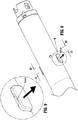
FIG. 10 is an enlarged view of the distal portion of the adapter assembly shown inFIG. 2 , with the retaining mechanism in a cleanse position; -
FIG. 11 is an enlarged view of the indicated area of detail shown inFIG. 10 ; and -
FIG. 12 is a cross-sectional end view taken along section line 12-12 shown inFIG. 10 . - Embodiments of the presently disclosed adapter assembly including a retaining mechanism for securing a removable trocar assembly therein will now be described in detail with reference to the drawings in which like reference numerals designate identical or corresponding elements in each of the several views. As is common in the art, the term "proximal" refers to that part or component closer to the user or operator, i.e. surgeon or clinician, while the term "distal" refers to that part or component further away from the user.
- Referring initially to
FIG. 1 , an adapter assembly according to an embodiment of the present disclosure, shown generally as adapter assembly 100, is a component of asurgical stapling device 10. Thesurgical stapling device 10 further includes a powered handle assembly 20, a loading unit 30, and an anvil assembly 40. Although shown and described with reference tosurgical stapling device 10, the aspects of the present disclosure may be modified for use with manual surgical stapling devices having various configurations, and with powered surgical stapling devices having alternative configurations. For a detailed description of exemplary surgical stapling devices, please refer to commonly ownedU.S. Pat. No. 9,023,014 U.S. Pat. Appl. Publ. No. 2012/0253329 ("the '329 application"), the content of each of which is incorporated by reference herein in their entirety. - With reference to
FIG. 2 , the adapter assembly 100 includes a proximal portion 102 configured for operable connection to the handle assembly 20 (FIG. 1 ) and a distal portion 104 configured for operable connection to the loading unit 30 (FIG. 1 ) and to the anvil assembly 40 (FIG. 1 ). Although shown and described as forming an integral unit, it is envisioned that the proximal and distal portions 102, 104 may be formed as separate units that are releasably securable to one another. - The adapter assembly 100 will only be described to the extent necessary to fully disclose the aspects of the present disclosure. For a detailed description of an exemplary adapter assembly, please refer to commonly owned
U.S. Pat. App. Pub. No. 2016/0106406 ("the '406 Publication"), the content of which is incorporated by reference herein in its entirety. - With additional reference to
FIG. 3 , the adapter assembly 100 includes an outer sleeve 106, and a connector housing 108 secured to a distal end of the outer sleeve 106. The connector housing 108 is configured to releasably secure an end effector, e.g., the end effector 30 (FIG. 1 ), to the adapter assembly 100. - A drive assembly 110 (
FIG. 3 ) extends through the outer sleeve 106 (FIG. 2 ) of the adapter assembly 100, and includes an inner flexible band assembly 112 and an outer flexible band assembly 114. The inner flexible band assembly 112 includes first and second flexible bands 112a, 112b (FIG. 7 ), and an inner pusher member 116 (FIG. 3 ) connected to the distal ends of the first and second flexible bands 112a, 112b (FIG. 7 ). Similarly, the outer flexible band assembly 114 includes first and second flexible bands 114a, 114b (FIG. 7 ), and an outer pusher member 118. For a detailed description of the structure and function of an exemplary drive assembly, please refer to the '406 Publication, the content of which was previously incorporated herein by reference in its entirety. - With additional reference to
FIG. 4 , the adapter assembly 100 further includes a trocar assembly 120, and a retaining mechanism 130 (FIG. 3 ) releasably securing the trocar assembly 120 relative to the outer sleeve 106 (FIG. 4 ) of the adapter assembly 100. The trocar assembly 120 will only be described to the extent necessary to describe the aspects of the present disclosure. For a detail description of the structure and function of an exemplary trocar assembly, please refer to the '406 Publication, the content of which was previously incorporated by reference herein in its entirety. - With particular reference to
FIG. 4 , the trocar assembly 120 of the adapter assembly 100 (FIG. 2 ) includes a trocar housing 122, a trocar member 124 slidably disposed within the trocar housing 122, and a drive screw 126 operably received within the trocar member 124 for axially moving the trocar member 124 relative to the trocar housing 122. The trocar housing 122 defines first and second locking openings 123a, 123b (FIG. 7 ) for receiving respective flange portions 150c, 152c of first and second plunger members 150, 152 (FIG. 7 ) of a retaining mechanism 130 of the adapter assembly 100. - With particular reference now to
FIG. 5 , the retaining mechanism 130 of the adapter assembly 100 includes a housing 132 supported within the outer sleeve 106 (FIG. 4 ) of the adapter assembly 100, first and second button members 140, 142 operably supported within the housing 132 and configured for engagement by a user, and first and second plunger members 150, 152 operably supported within the housing 132 and in engagement with the respect first and second button members 140, 142. As will be described in further detail below, first and second spring members 144, 146 are disposed within the housing 132 and bias the respective plunger members 150, 152 inward. - With continued reference to
FIG. 5 , the housing 132 of the retaining mechanism 130 includes a substantially cylindrical body portion 134 disposed within the outer sleeve 106 of the adapter assembly 100. The body portion 134 of the housing 132 defines a longitudinal cutout 131 for accommodating the first and second flexible bands 112a, 114a, 112b, 114b (FIG. 7 ) of the respective inner and outer flexible band assemblies 112, 114 of the adapter assembly 100, and for receiving the trocar assembly 120. - The body portion 134 of the housing 132 of the retaining mechanism 130 further defines first and second cutouts 133, 135 (
FIG. 6 ) with corresponding first and second slots 133a, 135a, and corresponding first and second sets of reliefs 133b, 135b. The first and second cutouts 133, 135 operably receive respective engagement portions 140a, 142a of the first and second button member 140, 142 of the retaining mechanism 130, while the first and second slots 133a, 135a accommodate attachment portions 140b, 142b of the first and second button members 140, 142, respectively. The body portion 134 of the housing 132 further defines first and second recesses 137, 139 that accommodate the respective first and second plunger members 150, 152. The first and second recesses 137, 139 each include a cylindrical portion 137a, 139b, connected to a rectangular portion 137b, 139b by a respective channel 137c, 139c. - As noted above, the first and second button members 140, 142 of the retaining mechanism 130 each includes the engagement portion 140a, 142a, respectively, and the attachment portions 140b, 142b, respectively, extending longitudinally from the respective engagement portions 140a, 142a. The first and second button members 140, 142 further include tab portions 140c, 142c, respectively, extending laterally outwardly from the respective first and second engagement portions 140a, 142a of the respective first and second button members 140, 142.
- The engagement portions 140a, 142a of the first and second button members 140, 142 of the retaining mechanism 130 are operably received within the respective first and second cutouts 133, 135 of the housing 132 of the retaining mechanism 130 while the attachment portions 140b, 142b are slidingly received through the slots 133a, 135a (
FIG. 6 ), respectively, corresponding to and in communication with the respective first and second cutouts 133, 135 (FIG. 12 ). The tab portions 140c, 142c of the respective first and second button members 140, 142 are received within the respective sets of reliefs 133b, 135b (FIG. 12 ) of the respective first and second cutouts 133, 135, and engage the outer sleeve 106 of the adapter assembly 100 to retain the respective first and second button members 140, 142 within the first and second cutouts 133b, 135b (FIG. 12 ), respectively. - The engagement portions 140a, 142a of the respective first and second button members 140, 142 of the retaining mechanism 130 each define a flush cutout 141 (
FIG. 6 ), 143, respectively. As will be described below, the engagement portions 140a, 142a of the respective first and second button members 140, 142 extend outwardly from the outer sleeve 106 of the adapter assembly 100 when the trocar assembly 120 is removed from the adapter assembly 100 to expose the flush cutouts 141, 143 of the respective first and second button members 140, 142. The flush cutouts 141, 143 enable cleaning and sterilizing of the interior of the adapter assembly 100 without removing the retaining mechanism 130 from within the adapter assembly 100. - As noted above, the engagement portions 140a, 142a of the respective first and second button members 140, 142 of the retaining mechanism 130 are configured for operable engagement by a user. As will be detail below, engagement of the engagement portions 140a, 142a by a user to move the respective first and second button members 140, 142 inward within the first and second cutouts 133, 135, respectively, cause outward movement of the plunger members 150, 152 which permits release of the trocar assembly 120 from within the adapter assembly 100 and/or facilitates receipt of the trocar assembly 120 within adapter assembly 100.
- The attachment portions 140b, 142b of the respective first and second button members 140, 142 of the retaining mechanism 130 each define an opening 145, 147 for receiving free ends 154, 156 of a flange portion 150b, 152b, respectively, of the respective first and second plunger members 150, 152. Receipt of free ends 154, 156 of the flange portions 150b, 152b of the respective first and second plunger members 150, 152 within the respective opening 145, 147 of the respective attachment portions 140b, 142b of the first and second button members 140, 142, respectively, couples the respective first and second plunger members 150, 152 to the first and second button members 140, 142, respectively, such that movement of the respective first and second button members 140, 142 causes corresponding movement of the respective first and second plunger members 150, 152.
- With continued reference to
FIG. 5 , each of the first and second plunger members 150, 152 of the retaining mechanism 130 include a cylindrical portion 150a, 152a, respectively, the flange portion 150b, 152b, respectively, extending outwardly from the respective cylindrical portion 150a, 152a, and a locking portion 150c, 152c extending longitudinally from the cylindrical portion 150a, 152a, respectively. The first and second plunger members 150, 152 each define a recess 151, 153, respectively, for receiving at least a portion of the first and second spring members 144, 146, respectively. - The cylindrical portions 150a, 152a of the respective first and second plunger members 150, 152 of the retaining mechanism 130 are received within the respective cylindrical portions 137a, 139a of the first and second recesses 137, 139, respectively, in the housing 132 of the retaining mechanism 130. The flange portions 150b, 152b of the respective first and second plunger members 150, 152 extend through the respective channel portions 137c, 139c of the first and second recesses 137, 139, respectively, with the free ends 154, 156 of the respective flange portions 150b, 152b of the respective first and second plunger members 150, 152 received within the respective rectangular portions 137b, 139b of the first and second recesses 137, 139, respectively. The flange portion 150b, 152b of the respective first and second plunger members 150, 152 engage the respective attachment portions 140b, 142b of the respective first and second button members 140, 142, within the respective rectangular portions 137b, 139b of the first and second recesses 137, 139, respectively.
- The first and second spring members 144, 146 of the retaining mechanism 130 are received within the respective recesses 151, 153 in the first and second plunger members 150, 152, respectively, and bias the respective first and second plunger members 150, 152 inwardly, as indicated by arrow "A" in
FIG. 6 . - Although the retaining mechanism 130 is shown as including first and second button members 150, 152, and corresponding first and second plunger members 140, 142, it is envisioned that the retaining mechanism 130 may include only one button member and only one corresponding plunger member.
- The first and second button members 150, 152 of the retaining mechanism 130, and the corresponding plunger members 140, 142 of the retaining mechanism 130 are movable between a first or lock position (
FIG. 6 ), a second or release position (FIG. 7 ), and a third or cleanse position (FIG. 11 ). As will be described in further detail below, when in the lock position, the trocar assembly 120 is secured within the adapter assembly 100, while in the release position, the trocar assembly 120 may be inserted into and withdrawn from the adapter assembly 100, and in the cleanse position, the first and second button members 140, 142 extend outwardly of the sleeve 106 of the adapter assembly 100 to expose the flush ports 141, 143 of the respective first and second button members 140, 142. - With reference to
FIG. 6 , the first and second button members 140, 142, and the corresponding plunger members 150, 152 are shown in the lock position. In the lock position the trocar assembly 120 is fully seated within the adapter assembly 100 and is securely engaged by the retaining mechanism 130. More particularly, when in the lock position, the locking portions 150c, 152c of the respective first and second plunger members 150, 152 are received within the respective first and second openings 123a, 123b in the trocar housing 122 of the trocar assembly 120. In addition, the engagement portions 140a, 142a of the respective first and second button members 140, 142 are flush with the outer sleeve 106 of the adapter assembly 100. Maintaining the first and second button members 140, 142 flush with the outer sleeve 106 facilitates insertion of the adapter assembly 100 through an access port, lumen, and/or incision, and/or may reduce the likelihood of contaminates getting within the adapter assembly. - Turning to
FIGS. 7 and8 , the first and second button members 150, 152, and the corresponding plunger members 150, 152 are shown in the release position. In the release position, the retaining mechanism 130 (FIG. 7 ) is disengaged from the trocar assembly 120 so the trocar assembly 120 may be removed from within the adapter assembly 100 (FIG. 8 ). More particularly, the first and second button members 140, 142 of the retaining mechanism 130 are depressed, as indicated by arrows "B" inFIG. 7 , to cause the respective first and second plunger members 150, 152 to move against the bias of the respective first and second spring members 144, 146, e.g., outwardly. As the first and second plunger members 150, 152 move outwardly, the flange portions 150c, 152c of the respective first and second plunger members 150, 152 withdraw from within the respective first and second openings 123a, 123b in the trocar housing 122 of the trocar assembly 120. With the first and second plunger members 150, 152 no longer engaging the trocar assembly 120, the trocar assembly 120 is removable from within the adapter assembly 100 for replacement and/or cleaning and sterilizng. - With reference now to
FIGS. 9-12 , the first and second button members 140, 142, and the corresponding plunger members 150, 152 of the retaining mechanism 130 are shown in the cleanse position. In the cleanse position the trocar assembly 120 is removed from the adapter assembly 100 and the first and second spring members 144, 146 bias the respective first and second plunger members 150, 152 inward. Without the trocar assembly 120 (FIG. 5 ) obstructing the movement of the first and second plunger members 150, 152, the first and second plunger members 150, 152 move closer together than when the first and second plunger members 150, 152 are in the lock position. In the cleanse position, the first and second button members 140, 142 are moved outwardly by the respective first and second plunger members 150, 152 beyond the outer sleeve 106 of the adapter assembly 100 by the respective first and second spring members 144, 146. - When the first and second button members 140, 142 of the retaining mechanism 130 extend beyond the outer sleeve 106 of the adapter assembly 100 the flush cutouts 141, 143 in the respective first and second button members 140, 142 are exposed to facilitate cleansing and sterilizing of the adapter assembly 100. As noted above, the tab portions 140c, 142c of the respective first and second button members 140, 142 engage an inner wall of the outer sleeve 106 of the adapter assembly 100 to maintain the respective first and second button member 140, 142 within the outer sleeve 106 of the adapter assembly 100. In this manner, the outer sleeve 106 acts as a limit stop.
- The adapter assembly 100 may be provided to a clinician with the trocar assembly 120 preloaded. In the event the trocar assembly 120 is provided to the clinician separate from the adapter assembly 100, the trocar assembly 120 is loaded into the adapter assembly 100 in the reverse order of removal. In order to accommodate the trocar assembly 120 through the longitudinal passage 131 of the housing 132 of the retaining mechanism 130 the first and second button members 140, 142 are depressed, as shown in
FIGS. 7 and8 , to move the first and second plunger members 150, 152, respectively, away from each other. As shown inFIG. 8 , when the first and second plunger members 150, 152 are moved away from each other, the longitudinal passage 131 through the housing 132 is unobstructed, thereby allowing for receipt of the trocar assembly 120 therethrough. - Once the trocar assembly 120 is received within the adapter assembly 100, the first and second button members 140, 142 are released thereby allowing the respective first and second plunger members 150, 152 to move towards one another in response to the bias of the first and second spring members 144, 146. If the first and second openings 123a, 123b in the trocar housing 122 of the trocar assembly 120 are aligned with the flange portions 150c, 152c, respectively, of the respective first and second plunger members 150, 152 the flange portions 150c, 152c of the respective first and second plunger members 150, 152 are received within the respective first and second openings 123a, 123b and the engagement portions 140a, 142c of the respective first and second button members 140, 142 become flush with the outer sleeve 106 of the adapter assembly 100. In the event that the locking portions 150c, 152c of the respective first and second plunger members 150, 152 do not align with the respective first and second openings 123a, 123b in the trocar housing 122, the engagement portions 140a, 142a of the respective first and second button members 140, 142 remain extended beyond the outer sleeve 106, thereby indicating to the clinician that the trocar assembly is not properly seated within the adapter assembly 100.
- Once the trocar assembly 120 is properly seated and secured within the adapter assembly 100, the adapter assembly 100 operates in a traditional manner.
- Persons skilled in the art will understand that the devices and methods specifically described herein and illustrated in the accompanying drawings are non-limiting exemplary embodiments. It is envisioned that the elements and features illustrated or described in connection with one exemplary embodiment may be combined with the elements and features of another without departing from the scope of the present disclosure. As well, one skilled in the art will appreciate further features and advantages of the disclosure based on the above-described embodiments. Accordingly, the disclosure is not to be limited by what has been particularly shown and described.
- The invention may be described by reference to the following numbered paragraphs:-
- 1. An adapter assembly for connecting a loading unit to a handle assembly, the adapter assembly comprising:
- an outer sleeve;
- a trocar assembly releasably securable with the outer sleeve, the trocar assembly including a trocar housing defining first and second openings; and
- a retaining mechanism configured to releasably secure the trocar assembly within the outer sleeve, the retaining mechanism including first and second button members configured for operable engagement by a user, the first and second button members are movable between a lock position with the first and second button members being flush with an outer surface of the outer sleeve, a release position in which the first and second buttons are recessed below the outer surface of the outer sleeve, and a cleanse position in which the first and second buttons extend beyond the outer surface of the outer sleeve, the trocar assembly securely coupled within the outer sleeve in the lock position.
- 2. The adapter assembly of paragraph 1, wherein the retaining mechanism further includes first and second plunger members in operable engagement with the respective first and second button members such that movement of the first button member results in corresponding movement of the first plunger member and movement of the second button member results in corresponding movement of the second plunger member.
- 3. The adapter assembly of
paragraph 2, wherein each of the first and second plunger members includes a flange portion configured for selective reception within the respective first and second openings of the trocar housing. - 4. The adapter assembly of
paragraph 2, wherein the retaining mechanism further includes first and second spring members for biasing the respective first and second plunger members towards each other. - 5. The adapter assembly of
paragraph 2, wherein the first and second plunger members are spaced apart when the first and second button members are in the lock position. - 6. The adapter assembly of
paragraph 2, wherein the first and second plunger members engage the trocar housing when the first and second button members are in the release position. - 7. The adapter assembly of
paragraph 2, wherein the first and second plunger members are spaced from the trocar assembly when the first and second button members are in the release position. - 8. The adapter assembly of paragraph 1, wherein each of the first and second button members includes a pair of tab portions, the tab portions being configured to engage the outer sleeve to retain the first and second button members within the adapter assembly.
- 9. The adapter assembly of paragraph 1, further including a connector housing for releasably securing a loading unit to the outer sleeve.
- 10. The adapter assembly of paragraph 1, wherein the trocar assembly includes a trocar member selectively extendable from the trocar housing.
Claims (10)
- An adapter assembly for connecting a loading unit to a handle assembly, the adapter assembly comprising:an outer sleeve;a trocar assembly releasably securable with the outer sleeve, the trocar assembly including a trocar housing defining first and second openings; anda retaining mechanism configured to releasably secure the trocar assembly within the outer sleeve, the retaining mechanism including first and second button members configured for operable engagement by a user, the first and second button members are movable between a lock position with the first and second button members being flush with an outer surface of the outer sleeve, a release position in which the first and second buttons are recessed below the outer surface of the outer sleeve, and a cleanse position in which the first and second buttons extend beyond the outer surface of the outer sleeve, the trocar assembly securely coupled within the outer sleeve in the lock position.
- The adapter assembly of claim 1, wherein the retaining mechanism further includes first and second plunger members in operable engagement with the respective first and second button members such that movement of the first button member results in corresponding movement of the first plunger member and movement of the second button member results in corresponding movement of the second plunger member.
- The adapter assembly of claim 2, wherein each of the first and second plunger members includes a flange portion configured for selective reception within the respective first and second openings of the trocar housing.
- The adapter assembly of claim 2 or claim 3, wherein the retaining mechanism further includes first and second spring members for biasing the respective first and second plunger members towards each other.
- The adapter assembly of any of claims 2 to 4, wherein the first and second plunger members are spaced apart when the first and second button members are in the lock position.
- The adapter assembly of any of claims 2 to 5, wherein the first and second plunger members engage the trocar housing when the first and second button members are in the release position.
- The adapter assembly of any of claims 2 to 6, wherein the first and second plunger members are spaced from the trocar assembly when the first and second button members are in the release position.
- The adapter assembly of any preceding claim, wherein each of the first and second button members includes a pair of tab portions, the tab portions being configured to engage the outer sleeve to retain the first and second button members within the adapter assembly.
- The adapter assembly of any preceding claim further including a connector housing for releasably securing a loading unit to the outer sleeve.
- The adapter assembly of any preceding claim, wherein the trocar assembly includes a trocar member selectively extendable from the trocar housing.
Applications Claiming Priority (1)
| Application Number | Priority Date | Filing Date | Title |
|---|---|---|---|
| US16/149,291 US10973544B2 (en) | 2018-10-02 | 2018-10-02 | Retaining mechanism for trocar assembly |
Publications (2)
| Publication Number | Publication Date |
|---|---|
| EP3632346A1 true EP3632346A1 (en) | 2020-04-08 |
| EP3632346B1 EP3632346B1 (en) | 2021-07-21 |
Family
ID=68109191
Family Applications (1)
| Application Number | Title | Priority Date | Filing Date |
|---|---|---|---|
| EP19200764.9A Active EP3632346B1 (en) | 2018-10-02 | 2019-10-01 | Retaining mechanism for trocar assembly |
Country Status (6)
| Country | Link |
|---|---|
| US (1) | US10973544B2 (en) |
| EP (1) | EP3632346B1 (en) |
| JP (1) | JP7393161B2 (en) |
| AU (1) | AU2019222827A1 (en) |
| CA (1) | CA3053115A1 (en) |
| ES (1) | ES2892024T3 (en) |
Cited By (1)
| Publication number | Priority date | Publication date | Assignee | Title |
|---|---|---|---|---|
| EP3939520A3 (en) * | 2020-07-13 | 2022-03-09 | Covidien LP | Methods and structure for confirming proper assembly of powered surgical stapling systems |
Families Citing this family (5)
| Publication number | Priority date | Publication date | Assignee | Title |
|---|---|---|---|---|
| US11426168B2 (en) * | 2019-07-05 | 2022-08-30 | Covidien Lp | Trocar coupling assemblies for a surgical stapler |
| US11446035B2 (en) * | 2019-06-24 | 2022-09-20 | Covidien Lp | Retaining mechanisms for trocar assemblies |
| US11517317B2 (en) * | 2020-01-06 | 2022-12-06 | Covidien Lp | Trocar release assemblies for a surgical stapler |
| US11426170B2 (en) * | 2020-03-24 | 2022-08-30 | Covidien Lp | Retaining mechanisms for trocar assemblies |
| US11426169B2 (en) * | 2020-03-24 | 2022-08-30 | Covidien Lp | Retaining mechanisms for trocar assemblies |
Citations (6)
| Publication number | Priority date | Publication date | Assignee | Title |
|---|---|---|---|---|
| US20120253329A1 (en) | 2007-09-21 | 2012-10-04 | Michael Zemlok | Hand held surgical handle assembly, surgical adapters for use between surgical handle assembly and surgical end effectors, and methods of use |
| US9023014B2 (en) | 2007-09-21 | 2015-05-05 | Covidien Lp | Quick connect assembly for use between surgical handle assembly and surgical accessories |
| US20160106406A1 (en) | 2014-10-21 | 2016-04-21 | Covidien Lp | Adapter, extension, and connector assemblies for surgical devices |
| EP3146905A1 (en) * | 2015-09-25 | 2017-03-29 | Covidien LP | Adapter assembly including a removable trocar assembly |
| EP3192462A1 (en) * | 2016-01-13 | 2017-07-19 | Covidien LP | Adapter assembly including a removable trocar assembly |
| US20170224345A1 (en) * | 2016-02-10 | 2017-08-10 | Covidien Lp | Adapter, extension, and connector assemblies for surgical devices |
Family Cites Families (346)
| Publication number | Priority date | Publication date | Assignee | Title |
|---|---|---|---|---|
| CA908529A (en) | 1972-08-29 | V. Astafiev Georgy | Surgical instrument for suturing hollow organs in infants | |
| DE1057729B (en) | 1954-03-29 | 1959-05-21 | Lameris Instr N V | Surgical device for connecting two parts of the intestine |
| GB787043A (en) | 1954-09-15 | 1957-11-27 | Sylvania Electric Prod | Method for production of silicon |
| CA736256A (en) | 1962-08-27 | 1966-06-14 | S. Kasoolin Viacheslav | Instrument for suturing esophagus to intestine or stomach |
| FR1461464A (en) | 1965-08-20 | 1966-02-25 | Niiex Khirurgicheskoi Apparatu | Surgical device for suturing organs |
| CH470170A (en) | 1968-02-02 | 1969-03-31 | Vnii Khirurgicheskoi Apparatur | Device for applying round anastomoses |
| US3638652A (en) | 1970-06-01 | 1972-02-01 | James L Kelley | Surgical instrument for intraluminal anastomosis |
| US3771526A (en) | 1972-02-07 | 1973-11-13 | P Rudie | Anastomosis clamp |
| US4304236A (en) | 1977-05-26 | 1981-12-08 | United States Surgical Corporation | Stapling instrument having an anvil-carrying part of particular geometric shape |
| US4603693A (en) | 1977-05-26 | 1986-08-05 | United States Surgical Corporation | Instrument for circular surgical stapling of hollow body organs and disposable cartridge therefor |
| US4573468A (en) | 1977-05-26 | 1986-03-04 | United States Surgical Corporation | Hollow body organ stapling instrument and disposable cartridge employing relief vents |
| NL7711347A (en) | 1977-10-17 | 1979-04-19 | Carl Robert Erik Daantje | Stapling instrument for joining intestine ends - has head coupling rod in two parts screwing together with hand grip |
| US4207898A (en) | 1978-03-27 | 1980-06-17 | Senco Products, Inc. | Intralumenal anastomosis surgical stapling instrument |
| US4198982A (en) | 1978-03-31 | 1980-04-22 | Memorial Hospital For Cancer And Allied Diseases | Surgical stapling instrument and method |
| DE2947107A1 (en) | 1978-12-07 | 1980-06-26 | United States Surgical Corp | ACCURATELY ALIGNED CARTRIDGE AND INSTRUMENT FOR CLAMPING ANASTOMOSES |
| SU1088712A1 (en) | 1979-11-14 | 1984-04-30 | Всесоюзный научно-исследовательский и испытательный институт медицинской техники | Apparatus for circular suture of blood vessels |
| AU534210B2 (en) | 1980-02-05 | 1984-01-12 | United States Surgical Corporation | Surgical staples |
| US4319576A (en) | 1980-02-26 | 1982-03-16 | Senco Products, Inc. | Intralumenal anastomosis surgical stapling instrument |
| US4289133A (en) | 1980-02-28 | 1981-09-15 | Senco Products, Inc. | Cut-through backup washer for the scalpel of an intraluminal surgical stapling instrument |
| US4606343A (en) | 1980-08-18 | 1986-08-19 | United States Surgical Corporation | Self-powered surgical fastening instrument |
| US4351466A (en) | 1980-10-16 | 1982-09-28 | United States Surgical Corporation | Disposable instrument for surgical fastening |
| US4379457A (en) | 1981-02-17 | 1983-04-12 | United States Surgical Corporation | Indicator for surgical stapler |
| US4476863A (en) | 1981-03-09 | 1984-10-16 | Kanshin Nikolai N | Surgical instrument for establishing circular coloanastomoses |
| US4632290A (en) | 1981-08-17 | 1986-12-30 | United States Surgical Corporation | Surgical stapler apparatus |
| US4576167A (en) | 1981-09-03 | 1986-03-18 | United States Surgical Corporation | Surgical stapler apparatus with curved shaft |
| SU1114405A1 (en) | 1982-02-23 | 1984-09-23 | Всесоюзный научно-исследовательский и испытательный институт медицинской техники | Surgical suturing apparatus for placing compression anastomoses on the organs of digestive tract |
| US4485817A (en) | 1982-05-28 | 1984-12-04 | United States Surgical Corporation | Surgical stapler apparatus with flexible shaft |
| US4473077A (en) | 1982-05-28 | 1984-09-25 | United States Surgical Corporation | Surgical stapler apparatus with flexible shaft |
| US4488523A (en) | 1982-09-24 | 1984-12-18 | United States Surgical Corporation | Flexible, hydraulically actuated device for applying surgical fasteners |
| DE3301713A1 (en) | 1983-01-20 | 1984-07-26 | Horst Dr. 3004 Isernhagen Ziegler | Surgical clip suture apparatus for producing circular joins |
| US4592354A (en) | 1983-10-11 | 1986-06-03 | Senmed, Inc. | Tissue retention spool for intraluminal anastomotic surgical stapling instrument and methods |
| US4505414A (en) | 1983-10-12 | 1985-03-19 | Filipi Charles J | Expandable anvil surgical stapler |
| US4550870A (en) | 1983-10-13 | 1985-11-05 | Alchemia Ltd. Partnership | Stapling device |
| IT1173284B (en) | 1984-02-16 | 1987-06-18 | Riccardo Rosati | CIRCULAR MECHANICAL STAPLING MACHINE |
| US4667673A (en) | 1984-03-12 | 1987-05-26 | American Cyanamid Company | Anastomotic device applicator and method |
| US4754909A (en) | 1984-08-09 | 1988-07-05 | Barker John M | Flexible stapler |
| US4671445A (en) | 1984-08-09 | 1987-06-09 | Baxter Travenol Laboratories, Inc. | Flexible surgical stapler assembly |
| US4703887A (en) | 1985-01-28 | 1987-11-03 | Ethicon, Inc. | Collapsible purse string aid for use with intraluminal stapling device |
| AU582625B2 (en) | 1985-01-28 | 1989-04-06 | Ethicon Inc. | Tissue gripper for use with intraluminal stapling device |
| US4665917A (en) | 1985-01-28 | 1987-05-19 | Ethicon, Inc. | Tissue gripper for use with intraluminal stapling device |
| JPS635697Y2 (en) | 1985-04-04 | 1988-02-17 | ||
| JPS62140776A (en) | 1985-12-16 | 1987-06-24 | 海老原 代師行 | Stapler |
| US4903697A (en) | 1986-03-27 | 1990-02-27 | Semion Resnick | Cartridge assembly for a surgical stapling instrument |
| US4700703A (en) | 1986-03-27 | 1987-10-20 | Semion Resnick | Cartridge assembly for a surgical stapling instrument |
| EP0267202B1 (en) | 1986-04-21 | 1993-11-03 | Globe Control Finanz Aktiengesellschaft | Anastomosis device |
| US4917114A (en) | 1986-10-17 | 1990-04-17 | United States Surgical Corporation | Surgical fastener and surgical stapling apparatus |
| US4752024A (en) | 1986-10-17 | 1988-06-21 | Green David T | Surgical fastener and surgical stapling apparatus |
| US4776506A (en) | 1986-11-13 | 1988-10-11 | United States Surgical Corporation | Surgical stapler apparatus |
| US4873977A (en) | 1987-02-11 | 1989-10-17 | Odis L. Avant | Stapling method and apparatus for vesicle-urethral re-anastomosis following retropubic prostatectomy and other tubular anastomosis |
| US5119983A (en) | 1987-05-26 | 1992-06-09 | United States Surgical Corporation | Surgical stapler apparatus |
| US5158222A (en) | 1987-05-26 | 1992-10-27 | United States Surgical Corp. | Surgical stapler apparatus |
| US5285944A (en) | 1987-05-26 | 1994-02-15 | United States Surgical Corporation | Surgical stapler apparatus |
| SU1616624A1 (en) | 1987-07-14 | 1990-12-30 | Предприятие П/Я А-3697 | Surgical suturing apparatus |
| SU1509052A1 (en) | 1988-01-18 | 1989-09-23 | С. А. Попов | Surgical suturing apparatus |
| US4907591A (en) | 1988-03-29 | 1990-03-13 | Pfizer Hospital Products Group, Inc. | Surgical instrument for establishing compression anastomosis |
| US5193731A (en) | 1988-07-01 | 1993-03-16 | United States Surgical Corporation | Anastomosis surgical stapling instrument |
| US5005749A (en) | 1988-07-01 | 1991-04-09 | United States Surgical Corp. | Anastomosis surgical stapling instrument |
| ES2011110A6 (en) | 1988-09-02 | 1989-12-16 | Lopez Hervas Pedro | Hydraulic device with flexible body for surgical anastomosts |
| US5197648A (en) | 1988-11-29 | 1993-03-30 | Gingold Bruce S | Surgical stapling apparatus |
| WO1990006085A1 (en) | 1988-11-29 | 1990-06-14 | Gingold Bruce S | Surgical stapling apparatus |
| US4893662A (en) | 1988-12-06 | 1990-01-16 | Vito Gervasi | Cutting tool |
| CH677728A5 (en) | 1989-10-17 | 1991-06-28 | Bieffe Medital Sa | |
| US5403333A (en) | 1990-08-28 | 1995-04-04 | Robert L. Kaster | Side-to-end vascular anastomotic staple apparatus |
| US5047039A (en) | 1990-09-14 | 1991-09-10 | Odis Lynn Avant | Method and apparatus for effecting dorsal vein ligation and tubular anastomosis and laparoscopic prostatectomy |
| US5253793A (en) | 1990-09-17 | 1993-10-19 | United States Surgical Corporation | Apparatus for applying two-part surgical fasteners |
| US5104025A (en) | 1990-09-28 | 1992-04-14 | Ethicon, Inc. | Intraluminal anastomotic surgical stapler with detached anvil |
| US5042707A (en) | 1990-10-16 | 1991-08-27 | Taheri Syde A | Intravascular stapler, and method of operating same |
| CA2055943C (en) | 1990-12-06 | 2003-09-23 | Daniel P. Rodak | Surgical fastening apparatus with locking mechanism |
| US5122156A (en) | 1990-12-14 | 1992-06-16 | United States Surgical Corporation | Apparatus for securement and attachment of body organs |
| US5222963A (en) | 1991-01-17 | 1993-06-29 | Ethicon, Inc. | Pull-through circular anastomosic intraluminal stapler with absorbable fastener means |
| JPH05508796A (en) | 1991-03-29 | 1993-12-09 | ペルーズ エリック | surgical staple inserter |
| US5221036A (en) | 1991-06-11 | 1993-06-22 | Haruo Takase | Surgical stapler |
| GR920100358A (en) | 1991-08-23 | 1993-06-07 | Ethicon Inc | Surgical anastomosis stapling instrument. |
| US5333773A (en) | 1991-08-23 | 1994-08-02 | Ethicon, Inc. | Sealing means for endoscopic surgical anastomosis stapling instrument |
| US5350104A (en) | 1991-08-23 | 1994-09-27 | Ethicon, Inc. | Sealing means for endoscopic surgical anastomosis stapling instrument |
| US5474223A (en) | 1991-10-18 | 1995-12-12 | United States Surgical Corporation | Surgical fastener applying apparatus |
| US5443198A (en) | 1991-10-18 | 1995-08-22 | United States Surgical Corporation | Surgical fastener applying apparatus |
| US5197649A (en) | 1991-10-29 | 1993-03-30 | The Trustees Of Columbia University In The City Of New York | Gastrointestinal endoscoptic stapler |
| US5433721A (en) | 1992-01-17 | 1995-07-18 | Ethicon, Inc. | Endoscopic instrument having a torsionally stiff drive shaft for applying fasteners to tissue |
| US5188638A (en) | 1992-02-06 | 1993-02-23 | Tzakis Andreas G | Apparatus and method for preforming anastomosis fastener securement of hollow organs |
| US5271543A (en) | 1992-02-07 | 1993-12-21 | Ethicon, Inc. | Surgical anastomosis stapling instrument with flexible support shaft and anvil adjusting mechanism |
| US5348259A (en) | 1992-02-10 | 1994-09-20 | Massachusetts Institute Of Technology | Flexible, articulable column |
| US5425738A (en) | 1992-04-08 | 1995-06-20 | American Cyanamid Company | Endoscopic anastomosis ring insertion device and method of use thereof |
| US5282810A (en) | 1992-04-08 | 1994-02-01 | American Cyanamid Company | Surgical anastomosis device |
| US5355897A (en) | 1992-04-16 | 1994-10-18 | Ethicon, Inc. | Method of performing a pyloroplasty/pylorectomy using a stapler having a shield |
| US5344059A (en) | 1992-05-19 | 1994-09-06 | United States Surgical Corporation | Surgical apparatus and anvil delivery system therefor |
| US5314435A (en) | 1992-05-19 | 1994-05-24 | United States Surgical Corporation | Anvil delivery system |
| US5658300A (en) | 1992-06-04 | 1997-08-19 | Olympus Optical Co., Ltd. | Tissue fixing surgical instrument, tissue-fixing device, and method of fixing tissues |
| JPH0647050A (en) | 1992-06-04 | 1994-02-22 | Olympus Optical Co Ltd | Tissue suture and ligature device |
| US5360154A (en) | 1992-07-17 | 1994-11-01 | United States Surgical Corporation | Apparatus for creating partial anastomoses |
| US5330486A (en) | 1992-07-29 | 1994-07-19 | Wilk Peter J | Laparoscopic or endoscopic anastomosis technique and associated instruments |
| US5261920A (en) | 1992-08-21 | 1993-11-16 | Ethicon, Inc. | Anvil bushing for circular stapler |
| US5368215A (en) | 1992-09-08 | 1994-11-29 | United States Surgical Corporation | Surgical apparatus and detachable anvil rod therefor |
| US5309927A (en) | 1992-10-22 | 1994-05-10 | Ethicon, Inc. | Circular stapler tissue retention spring method |
| US5314436A (en) | 1992-10-30 | 1994-05-24 | Wilk Peter J | Method and apparatus for performing end-to-end anastomoses |
| US5404870A (en) | 1993-05-28 | 1995-04-11 | Ethicon, Inc. | Method of using a transanal inserter |
| US5503320A (en) | 1993-08-19 | 1996-04-02 | United States Surgical Corporation | Surgical apparatus with indicator |
| US5522534A (en) | 1993-10-01 | 1996-06-04 | United States Surgical Corporation | Anvil for surgical stapler |
| US5447514A (en) | 1993-10-01 | 1995-09-05 | United States Surgical Corporation | Circular anastomosis device |
| US5454825A (en) | 1993-10-01 | 1995-10-03 | United States Surgical Corporation | Circular anastomosis device with seal |
| US5437684A (en) | 1993-10-01 | 1995-08-01 | United States Surgical Corporation | Circular anastomosis device |
| CA2132917C (en) | 1993-10-07 | 2004-12-14 | John Charles Robertson | Circular anastomosis device |
| US5503635A (en) | 1993-11-12 | 1996-04-02 | United States Surgical Corporation | Apparatus and method for performing compressional anastomoses |
| DE4407668A1 (en) | 1994-03-09 | 1995-09-14 | Ferdinand Dr Koeckerling | Surgical anastomotic ring setting device |
| US5464415A (en) | 1994-03-15 | 1995-11-07 | Chen; Te-Chuan | Sutureless intestinal anastomosis gun |
| US5860581A (en) | 1994-03-24 | 1999-01-19 | United States Surgical Corporation | Anvil for circular stapler |
| US5715987A (en) | 1994-04-05 | 1998-02-10 | Tracor Incorporated | Constant width, adjustable grip, staple apparatus and method |
| CA2147800C (en) | 1994-05-26 | 2006-07-11 | John Charles Robertson | Circular anastomosis device |
| ES2203641T3 (en) | 1994-06-17 | 2004-04-16 | Heartport, Inc. | SURGICAL STAPLING APPARATUS. |
| US5732872A (en) | 1994-06-17 | 1998-03-31 | Heartport, Inc. | Surgical stapling instrument |
| US5881943A (en) | 1994-06-17 | 1999-03-16 | Heartport, Inc. | Surgical anastomosis apparatus and method thereof |
| CA2146508C (en) | 1994-08-25 | 2006-11-14 | Robert H. Schnut | Anvil for circular stapler |
| US5685474A (en) | 1994-10-04 | 1997-11-11 | United States Surgical Corporation | Tactile indicator for surgical instrument |
| US7235089B1 (en) | 1994-12-07 | 2007-06-26 | Boston Scientific Corporation | Surgical apparatus and method |
| US5868760A (en) | 1994-12-07 | 1999-02-09 | Mcguckin, Jr.; James F. | Method and apparatus for endolumenally resectioning tissue |
| US5720755A (en) | 1995-01-18 | 1998-02-24 | Dakov; Pepi | Tubular suturing device and methods of use |
| US5904697A (en) | 1995-02-24 | 1999-05-18 | Heartport, Inc. | Devices and methods for performing a vascular anastomosis |
| DE19509115C2 (en) | 1995-03-16 | 1997-11-27 | Deutsche Forsch Luft Raumfahrt | Surgical device for preparing an anastomosis using minimally invasive surgical techniques |
| US5769841A (en) | 1995-06-13 | 1998-06-23 | Electroscope, Inc. | Electrosurgical apparatus for laparoscopic and like procedures |
| US5641111A (en) | 1995-06-28 | 1997-06-24 | Ethicon Endo-Surgery, Inc. | Surgical stapling instrument with anvil cutting guide |
| US5749896A (en) | 1995-07-18 | 1998-05-12 | Cook; Melvin S. | Staple overlap |
| US5839639A (en) | 1995-08-17 | 1998-11-24 | Lasersurge, Inc. | Collapsible anvil assembly and applicator instrument |
| US5814055A (en) | 1995-09-19 | 1998-09-29 | Ethicon Endo-Surgery, Inc. | Surgical clamping mechanism |
| JP3207436B2 (en) | 1995-10-31 | 2001-09-10 | オチコン アクツイエセルスカプ | Anastomotic device for use in performing an end-to-side anastomosis |
| US5836503A (en) | 1996-04-22 | 1998-11-17 | United States Surgical Corporation | Insertion device for surgical apparatus |
| US6050472A (en) | 1996-04-26 | 2000-04-18 | Olympus Optical Co., Ltd. | Surgical anastomosis stapler |
| US6119913A (en) | 1996-06-14 | 2000-09-19 | Boston Scientific Corporation | Endoscopic stapler |
| US6024748A (en) | 1996-07-23 | 2000-02-15 | United States Surgical Corporation | Singleshot anastomosis instrument with detachable loading unit and method |
| US20020019642A1 (en) | 1996-07-23 | 2002-02-14 | Keith Milliman | Anastomosis instrument and method for performing same |
| US6440146B2 (en) | 1996-07-23 | 2002-08-27 | United States Surgical Corporation | Anastomosis instrument and method |
| US5833698A (en) | 1996-07-23 | 1998-11-10 | United States Surgical Corporation | Anastomosis instrument and method |
| US5855312A (en) | 1996-07-25 | 1999-01-05 | Toledano; Haviv | Flexible annular stapler for closed surgery of hollow organs |
| US5853395A (en) | 1997-02-18 | 1998-12-29 | Dexterity, Inc. | Extracorporeal pneumoperitoneum enclosure and method of use |
| US6338737B1 (en) | 1997-07-17 | 2002-01-15 | Haviv Toledano | Flexible annular stapler for closed surgery of hollow organs |
| US5865361A (en) | 1997-09-23 | 1999-02-02 | United States Surgical Corporation | Surgical stapling apparatus |
| US6117148A (en) | 1997-10-17 | 2000-09-12 | Ravo; Biagio | Intraluminal anastomotic device |
| US5951576A (en) | 1998-03-02 | 1999-09-14 | Wakabayashi; Akio | End-to-side vascular anastomosing stapling device |
| US6279809B1 (en) | 1998-03-10 | 2001-08-28 | Enrico Nicolo | Circular stapler for side to end, side to side and end to side anastomosis |
| US6517566B1 (en) | 1998-05-11 | 2003-02-11 | Surgical Connections, Inc. | Devices and methods for treating e.g. urinary stress incontinence |
| WO1999058081A2 (en) | 1998-05-11 | 1999-11-18 | Hovland Claire T | Devices and methods for treating e.g. urinary stress incontinence |
| US6585144B2 (en) | 1998-06-19 | 2003-07-01 | Acimed Life Systems, Inc. | Integrated surgical staple retainer for a full thickness resectioning device |
| US6478210B2 (en) | 2000-10-25 | 2002-11-12 | Scimed Life Systems, Inc. | Method and device for full thickness resectioning of an organ |
| US6601749B2 (en) | 1998-06-19 | 2003-08-05 | Scimed Life Systems, Inc. | Multi fire full thickness resectioning device |
| US6629630B2 (en) | 1998-06-19 | 2003-10-07 | Scimed Life Systems, Inc. | Non-circular resection device and endoscope |
| US6126058A (en) | 1998-06-19 | 2000-10-03 | Scimed Life Systems, Inc. | Method and device for full thickness resectioning of an organ |
| DE19837258A1 (en) | 1998-08-17 | 2000-03-02 | Deutsch Zentr Luft & Raumfahrt | Device for operating a surgical instrument for anastomosis of hollow organs |
| DE19836950B4 (en) | 1998-08-17 | 2004-09-02 | Deutsches Zentrum für Luft- und Raumfahrt e.V. | Surgical instrument in the form of a suturing device |
| US6203553B1 (en) | 1999-09-08 | 2001-03-20 | United States Surgical | Stapling apparatus and method for heart valve replacement |
| US6102271A (en) | 1998-11-23 | 2000-08-15 | Ethicon Endo-Surgery, Inc. | Circular stapler for hemorrhoidal surgery |
| US6142933A (en) | 1998-11-23 | 2000-11-07 | Ethicon Endo-Surgery, Inc. | Anoscope for hemorrhoidal surgery |
| US6083241A (en) | 1998-11-23 | 2000-07-04 | Ethicon Endo-Surgery, Inc. | Method of use of a circular stapler for hemorrhoidal procedure |
| US6652542B2 (en) | 1999-04-16 | 2003-11-25 | Integrated Vascular Interventional Technologies, L.C. (Ivit, Lc) | External anastomosis operators and related systems for anastomosis |
| US6626921B2 (en) | 1999-04-16 | 2003-09-30 | Integrated Vascular Interventional Technologies, L.C. | Externally positioned anvil apparatus for cutting anastomosis |
| US6551334B2 (en) | 1999-04-16 | 2003-04-22 | Integrated Vascular Interventional Technologies, Lc | Externally directed anastomosis systems and externally positioned anastomosis fenestra cutting apparatus |
| US6743244B2 (en) | 1999-04-16 | 2004-06-01 | Integrated Vascular Interventional Technologies, L.C. | Soft anvil apparatus for cutting anastomosis fenestra |
| US6402008B1 (en) | 1999-04-19 | 2002-06-11 | Deborah A. Lucas | Surgical stapler assembly with interchangeable heads |
| US6068636A (en) | 1999-04-23 | 2000-05-30 | Chen; Te-Chuan | Intra-intestinal bypass gun |
| US6793652B1 (en) | 1999-06-02 | 2004-09-21 | Power Medical Interventions, Inc. | Electro-mechanical surgical device |
| US6315184B1 (en) | 1999-06-02 | 2001-11-13 | Powermed, Inc. | Stapling device for use with an electromechanical driver device for use with anastomosing, stapling, and resecting instruments |
| US8025199B2 (en) | 2004-02-23 | 2011-09-27 | Tyco Healthcare Group Lp | Surgical cutting and stapling device |
| US6443973B1 (en) | 1999-06-02 | 2002-09-03 | Power Medical Interventions, Inc. | Electromechanical driver device for use with anastomosing, stapling, and resecting instruments |
| US6491201B1 (en) | 2000-02-22 | 2002-12-10 | Power Medical Interventions, Inc. | Fluid delivery mechanism for use with anastomosing, stapling, and resecting instruments |
| US6264087B1 (en) | 1999-07-12 | 2001-07-24 | Powermed, Inc. | Expanding parallel jaw device for use with an electromechanical driver device |
| US6981941B2 (en) | 1999-06-02 | 2006-01-03 | Power Medical Interventions | Electro-mechanical surgical device |
| US6716233B1 (en) | 1999-06-02 | 2004-04-06 | Power Medical Interventions, Inc. | Electromechanical driver and remote surgical instrument attachment having computer assisted control capabilities |
| US7032798B2 (en) | 1999-06-02 | 2006-04-25 | Power Medical Interventions, Inc. | Electro-mechanical surgical device |
| US7540839B2 (en) | 1999-10-14 | 2009-06-02 | Atropos Limited | Wound retractor |
| AU3290201A (en) | 2000-01-18 | 2001-07-31 | Tyco Healthcare | Anastomosis instrument and method for performing same |
| US6193129B1 (en) | 2000-01-24 | 2001-02-27 | Ethicon Endo-Surgery, Inc. | Cutting blade for a surgical anastomosis stapling instrument |
| HU225908B1 (en) | 2000-01-24 | 2007-12-28 | Ethicon Endo Surgery Europe | Surgical circular stapling head |
| US6533157B1 (en) | 2000-02-22 | 2003-03-18 | Power Medical Interventions, Inc. | Tissue stapling attachment for use with an electromechanical driver device |
| US6488197B1 (en) | 2000-02-22 | 2002-12-03 | Power Medical Interventions, Inc. | Fluid delivery device for use with anastomosing resecting and stapling instruments |
| US6273897B1 (en) | 2000-02-29 | 2001-08-14 | Ethicon, Inc. | Surgical bettress and surgical stapling apparatus |
| CA2402313C (en) | 2000-03-06 | 2009-03-03 | Tyco Healthcare Group Lp | Apparatus and method for performing a bypass procedure in a digestive system |
| IL139788A (en) | 2000-11-20 | 2006-10-05 | Minelu Zonnenschein | Stapler for endoscopes |
| US6592596B1 (en) | 2000-05-10 | 2003-07-15 | Scimed Life Systems, Inc. | Devices and related methods for securing a tissue fold |
| US20040267310A1 (en) | 2000-10-20 | 2004-12-30 | Racenet David C | Directionally biased staple and anvil assembly for forming the staple |
| US8286845B2 (en) | 2000-11-27 | 2012-10-16 | Boston Scientific Scimed, Inc. | Full thickness resection device control handle |
| US6821282B2 (en) | 2000-11-27 | 2004-11-23 | Scimed Life Systems, Inc. | Full thickness resection device control handle |
| US6398795B1 (en) | 2000-11-30 | 2002-06-04 | Scimed Life Systems, Inc. | Stapling and cutting in resectioning for full thickness resection devices |
| US6439446B1 (en) | 2000-12-01 | 2002-08-27 | Stephen J. Perry | Safety lockout for actuator shaft |
| US6503259B2 (en) | 2000-12-27 | 2003-01-07 | Ethicon, Inc. | Expandable anastomotic device |
| US6632237B2 (en) | 2001-01-11 | 2003-10-14 | Bio-Seal Tech, Inc. | Device and method for sealing a puncture in a blood vessel |
| JP4130584B2 (en) | 2001-01-24 | 2008-08-06 | タイコ ヘルスケア グループ リミテッド パートナーシップ | Anastomosis instrument and method for performing anastomosis |
| EP1359851B1 (en) | 2001-01-31 | 2010-09-22 | Rex Medical, Inc. | Apparatus for stapling and resectioning gastro-edophageal tissue |
| US6769590B2 (en) | 2001-04-02 | 2004-08-03 | Susan E. Vresh | Luminal anastomotic device and method |
| CA2442680C (en) | 2001-04-03 | 2010-03-23 | Tyco Healthcare Group Lp | Surgical stapling device |
| US6632227B2 (en) | 2001-08-24 | 2003-10-14 | Scimed Life Systems, Inc. | Endoscopic resection devices |
| JP2005502421A (en) | 2001-09-17 | 2005-01-27 | ガルシア・ビセンテ ヒレテ | Craniotomy bone anchor |
| US6578751B2 (en) | 2001-09-26 | 2003-06-17 | Scimed Life Systems, Inc. | Method of sequentially firing staples using springs and a rotary or linear shutter |
| US20070060952A1 (en) | 2005-09-02 | 2007-03-15 | Roby Mark S | Surgical stapling device with coated knife blade |
| US6605098B2 (en) | 2001-09-28 | 2003-08-12 | Ethicon, Inc. | Surgical device for creating an anastomosis between first and second hollow organs |
| WO2003030745A1 (en) | 2001-10-05 | 2003-04-17 | Tyco Healthcare Group Lp | Tilt top anvil for a surgical fastener device |
| US6605078B2 (en) | 2001-11-26 | 2003-08-12 | Scimed Life Systems, Inc. | Full thickness resection device |
| DE10158246C1 (en) | 2001-11-28 | 2003-08-21 | Ethicon Endo Surgery Europe | Surgical stapling instrument |
| US20030111507A1 (en) | 2001-12-14 | 2003-06-19 | George Nunez | Balloon actuator for use in a resectioning device |
| US6981979B2 (en) | 2001-12-14 | 2006-01-03 | Enrico Nicolo | Surgical anastomotic devices |
| US6905504B1 (en) | 2002-02-26 | 2005-06-14 | Cardica, Inc. | Tool for performing end-to-end anastomosis |
| US7128748B2 (en) | 2002-03-26 | 2006-10-31 | Synovis Life Technologies, Inc. | Circular stapler buttress combination |
| US7141055B2 (en) | 2002-04-24 | 2006-11-28 | Surgical Connections, Inc. | Resection and anastomosis devices and methods |
| ES2377483T3 (en) | 2002-04-25 | 2012-03-28 | Tyco Healthcare Group Lp | Surgical instruments that include microelectromechanical systems (MEMS) |
| US6685079B2 (en) | 2002-05-24 | 2004-02-03 | Scimed Life Systems, Inc. | Full thickness resectioning device |
| US7195142B2 (en) | 2003-05-30 | 2007-03-27 | Tyco Healthcare Group Lp | End-to-end anastomosis instrument and method for performing same |
| US6769594B2 (en) | 2002-05-31 | 2004-08-03 | Tyco Healthcare Group, Lp | End-to-end anastomosis instrument and method for performing same |
| ES2366425T3 (en) | 2002-06-17 | 2011-10-20 | Tyco Healthcare Group Lp | ANNULAR SUPPORT STRUCTURES. |
| IL150855A (en) | 2002-07-22 | 2007-06-03 | Leonid Monassevitch | Intratubular anastomosis apparatus |
| AU2003279147B2 (en) | 2002-10-04 | 2008-10-09 | Covidien Lp | Surgical stapling device |
| EP2430985B1 (en) | 2002-10-04 | 2017-06-14 | Covidien LP | Pneumatic powered surgical stapling device |
| US7220237B2 (en) | 2002-10-23 | 2007-05-22 | Satiety, Inc. | Method and device for use in endoscopic organ procedures |
| JP2004147969A (en) | 2002-10-31 | 2004-05-27 | Univ Waseda | Device and implement for anastomosis |
| CA2508246A1 (en) | 2002-12-16 | 2004-07-15 | Edrich Vascular Devices, Inc. | Multiple stapling device for narrow blood vessels |
| WO2004058080A2 (en) | 2002-12-20 | 2004-07-15 | Tyco Healthcare Group, Lp | Vacuum assisted surgical stapler |
| US6852122B2 (en) | 2003-01-23 | 2005-02-08 | Cordis Corporation | Coated endovascular AAA device |
| KR100547166B1 (en) | 2003-04-11 | 2006-01-26 | 허윤석 | Improved circular stapler |
| CA2529446C (en) | 2003-06-20 | 2012-12-18 | Tyco Healthcare Group, Lp | Surgical stapling device |
| EP2620104A3 (en) | 2003-07-16 | 2014-05-14 | Covidien LP | Surgical stapling device with tissue tensioner |
| US7686201B2 (en) | 2003-09-01 | 2010-03-30 | Tyco Healthcare Group Lp | Circular stapler for hemorrhoid operations |
| US7547312B2 (en) | 2003-09-17 | 2009-06-16 | Gore Enterprise Holdings, Inc. | Circular stapler buttress |
| US7309341B2 (en) | 2003-09-30 | 2007-12-18 | Ethicon Endo-Surgery, Inc. | Single lumen anastomosis applier for self-deploying fastener |
| WO2005037084A2 (en) | 2003-10-17 | 2005-04-28 | Tyco Healthcare Group, Lp | Surgical stapling device |
| US8590764B2 (en) | 2003-12-24 | 2013-11-26 | Boston Scientific Scimed, Inc. | Circumferential full thickness resectioning device |
| US7585306B2 (en) | 2003-12-24 | 2009-09-08 | Maquet Cardiovascular Llc | Anastomosis device, tools and methods of using |
| US6953138B1 (en) | 2004-02-18 | 2005-10-11 | Frank W. Dworak | Surgical stapler anvil with nested staple forming pockets |
| US7086267B2 (en) | 2004-02-18 | 2006-08-08 | Frank W. Dworak | Metal-forming die and method for manufacturing same |
| US7118528B1 (en) | 2004-03-16 | 2006-10-10 | Gregory Piskun | Hemorrhoids treatment method and associated instrument assembly including anoscope and cofunctioning tissue occlusion device |
| US8181840B2 (en) | 2004-03-19 | 2012-05-22 | Tyco Healthcare Group Lp | Tissue tensioner assembly and approximation mechanism for surgical stapling device |
| ES2400050T3 (en) | 2004-03-19 | 2013-04-05 | Covidien Lp | Anvil set with improved cutting ring |
| US20060000869A1 (en) | 2004-05-17 | 2006-01-05 | Datascope Investment Corp. | Surgical stapling system |
| JP4257270B2 (en) | 2004-07-14 | 2009-04-22 | オリンパス株式会社 | Biological tissue suturing method and biological tissue suturing device |
| US8317074B2 (en) | 2004-07-28 | 2012-11-27 | Ethicon Endo-Surgery, Inc. | Electroactive polymer-based articulation mechanism for circular stapler |
| US7182239B1 (en) | 2004-08-27 | 2007-02-27 | Myers Stephan R | Segmented introducer device for a circular surgical stapler |
| KR100646762B1 (en) | 2004-09-10 | 2006-11-23 | 인하대학교 산학협력단 | A staple for operation and a stapler for operation provided with the same |
| US8372094B2 (en) | 2004-10-15 | 2013-02-12 | Covidien Lp | Seal element for anastomosis |
| US7845536B2 (en) | 2004-10-18 | 2010-12-07 | Tyco Healthcare Group Lp | Annular adhesive structure |
| EP1802237B1 (en) | 2004-10-18 | 2018-08-08 | Covidien LP | Compression anastomosis device |
| JP4836090B2 (en) | 2004-10-18 | 2011-12-14 | タイコ ヘルスケア グループ リミテッド パートナーシップ | Annular adhesive structure |
| US7455682B2 (en) | 2004-10-18 | 2008-11-25 | Tyco Healthcare Group Lp | Structure containing wound treatment material |
| US7938307B2 (en) | 2004-10-18 | 2011-05-10 | Tyco Healthcare Group Lp | Support structures and methods of using the same |
| WO2006044494A2 (en) | 2004-10-18 | 2006-04-27 | Tyco Healthcare Group, Lp | Adhesive suture structure and methods of using the same |
| US7717313B2 (en) | 2004-10-18 | 2010-05-18 | Tyco Healthcare Group Lp | Surgical apparatus and structure for applying sprayable wound treatment material |
| ES2654250T3 (en) | 2004-10-18 | 2018-02-12 | Covidien Lp | Structure for applying sprayable wound treatment material |
| ITMI20042132A1 (en) | 2004-11-05 | 2005-02-05 | Ethicon Endo Surgery Inc | DEVICE AND METHOD FOR OBESITY THERAPY |
| US7207168B2 (en) | 2004-11-19 | 2007-04-24 | The Schnipke Family Limited Liability Company | Apparatus and method for inserting staple drivers in a cartridge |
| WO2006079260A1 (en) | 2005-01-26 | 2006-08-03 | Suzhou Touchstone International Medical Science Co., Ltd | A rotatable cutter head of a surgical stapler |
| US20060201989A1 (en) | 2005-03-11 | 2006-09-14 | Ojeda Herminio F | Surgical anvil and system for deploying the same |
| US9364229B2 (en) | 2005-03-15 | 2016-06-14 | Covidien Lp | Circular anastomosis structures |
| US7717312B2 (en) | 2005-06-03 | 2010-05-18 | Tyco Healthcare Group Lp | Surgical instruments employing sensors |
| US7959050B2 (en) | 2005-07-26 | 2011-06-14 | Ethicon Endo-Surgery, Inc | Electrically self-powered surgical instrument with manual release |
| US8627995B2 (en) | 2006-05-19 | 2014-01-14 | Ethicon Endo-Sugery, Inc. | Electrically self-powered surgical instrument with cryptographic identification of interchangeable part |
| US8573462B2 (en) | 2006-05-19 | 2013-11-05 | Ethicon Endo-Surgery, Inc. | Electrical surgical instrument with optimized power supply and drive |
| US20070029363A1 (en) | 2005-08-07 | 2007-02-08 | Sergey Popov | Surgical apparatus with remote drive |
| US7398908B2 (en) | 2005-08-15 | 2008-07-15 | Tyco Healthcare Group Lp | Surgical stapling instruments including a cartridge having multiple staple sizes |
| US7401721B2 (en) | 2005-08-15 | 2008-07-22 | Tyco Healthcare Group Lp | Surgical stapling instruments including a cartridge having multiple staple sizes |
| US7407075B2 (en) | 2005-08-15 | 2008-08-05 | Tyco Healthcare Group Lp | Staple cartridge having multiple staple sizes for a surgical stapling instrument |
| US8579178B2 (en) | 2005-08-15 | 2013-11-12 | Covidien Lp | Surgical stapling instruments including a cartridge having multiple staples sizes |
| US7771440B2 (en) | 2005-08-18 | 2010-08-10 | Ethicon Endo-Surgery, Inc. | Method and apparatus for endoscopically performing gastric reduction surgery in a single pass |
| US20070194082A1 (en) | 2005-08-31 | 2007-08-23 | Morgan Jerome R | Surgical stapling device with anvil having staple forming pockets of varying depths |
| CN2868208Y (en) | 2005-12-14 | 2007-02-14 | 苏州天臣国际医疗科技有限公司 | Tubular binding instrument having automatic safety unit |
| US7422138B2 (en) | 2006-02-01 | 2008-09-09 | Ethicon Endo-Surgery, Inc. | Elliptical intraluminal surgical stapler for anastomosis |
| US7793813B2 (en) | 2006-02-28 | 2010-09-14 | Tyco Healthcare Group Lp | Hub for positioning annular structure on a surgical device |
| WO2007112059A2 (en) | 2006-03-23 | 2007-10-04 | Edrich Health Technologies , Inc. | Vascular anastomotic staplers |
| US8357085B2 (en) | 2009-03-31 | 2013-01-22 | Ethicon Endo-Surgery, Inc. | Devices and methods for providing access into a body cavity |
| US8206294B2 (en) | 2008-09-30 | 2012-06-26 | Ethicon Endo-Surgery, Inc. | Surgical access device with flexible seal channel |
| EP1875870B1 (en) | 2006-07-07 | 2009-12-02 | Ethicon Endo-Surgery, Inc. | A surgical stapling instrument. |
| US7527185B2 (en) | 2006-07-12 | 2009-05-05 | Niti Surgical Solutions Ltd. | Compression anastomosis ring assembly and applicator for use therewith |
| US8720766B2 (en) | 2006-09-29 | 2014-05-13 | Ethicon Endo-Surgery, Inc. | Surgical stapling instruments and staples |
| ES2359354T3 (en) | 2007-03-07 | 2011-05-20 | Covidien Ag | STAPLER FOR MUCOSECTOMY. |
| US7673782B2 (en) | 2007-03-15 | 2010-03-09 | Ethicon Endo-Surgery, Inc. | Surgical stapling instrument having a releasable buttress material |
| US7978403B2 (en) | 2007-05-10 | 2011-07-12 | Stc.Unm | Imaging interferometric microscopy |
| US8038045B2 (en) | 2007-05-25 | 2011-10-18 | Tyco Healthcare Group Lp | Staple buttress retention system |
| US7600663B2 (en) | 2007-07-05 | 2009-10-13 | Green David T | Apparatus for stapling and incising tissue |
| US7967181B2 (en) | 2007-08-29 | 2011-06-28 | Tyco Healthcare Group Lp | Rotary knife cutting systems |
| US20090082785A1 (en) | 2007-09-24 | 2009-03-26 | Milliman Keith L | Anvil Delivery Device Accessory |
| US8011554B2 (en) | 2008-01-09 | 2011-09-06 | Tyco Healthcare Group, Lp | Raised boss for staple guide |
| US8733611B2 (en) | 2008-03-12 | 2014-05-27 | Covidien Lp | Ratcheting mechanism for surgical stapling device |
| US8020741B2 (en) | 2008-03-18 | 2011-09-20 | Barosense, Inc. | Endoscopic stapling devices and methods |
| US8231041B2 (en) | 2008-04-14 | 2012-07-31 | Tyco Healthcare Group Lp | Variable compression surgical fastener cartridge |
| WO2009133875A1 (en) | 2008-04-30 | 2009-11-05 | 学校法人自治医科大学 | Surgical system and surgical method for natural orifice transluminal endoscopic surgery (notes) |
| US8403889B2 (en) | 2008-06-25 | 2013-03-26 | Covidien Lp | Access assembly |
| US8011551B2 (en) | 2008-07-01 | 2011-09-06 | Tyco Healthcare Group Lp | Retraction mechanism with clutch-less drive for use with a surgical apparatus |
| US8678264B2 (en) | 2008-07-07 | 2014-03-25 | Covidien Lp | Surgical instrument with elongated channel |
| US8109426B2 (en) | 2008-08-12 | 2012-02-07 | Tyco Healthcare Group Lp | Surgical tilt anvil assembly |
| US8672931B2 (en) | 2008-08-18 | 2014-03-18 | 3JT Enterprises, LLC | Cryosurgical device with metered dose |
| US8113405B2 (en) | 2008-09-03 | 2012-02-14 | Tyco Healthcare Group, Lp | Surgical instrument with indicator |
| US20100051668A1 (en) | 2008-09-03 | 2010-03-04 | Milliman Keith L | Surgical instrument with indicator |
| US8181838B2 (en) | 2008-09-10 | 2012-05-22 | Tyco Healthcare Group Lp | Surgical stapling device |
| US7837080B2 (en) | 2008-09-18 | 2010-11-23 | Ethicon Endo-Surgery, Inc. | Surgical stapling instrument with device for indicating when the instrument has cut through tissue |
| US20100084453A1 (en) | 2008-10-03 | 2010-04-08 | Changzhou Waston Medical Appliance Co., Ltd | Circular stapler |
| US7918377B2 (en) | 2008-10-16 | 2011-04-05 | Ethicon Endo-Surgery, Inc. | Surgical stapling instrument with apparatus for providing anvil position feedback |
| US8231042B2 (en) | 2008-11-06 | 2012-07-31 | Tyco Healthcare Group Lp | Surgical stapler |
| US7886951B2 (en) | 2008-11-24 | 2011-02-15 | Tyco Healthcare Group Lp | Pouch used to deliver medication when ruptured |
| US8770460B2 (en) | 2008-12-23 | 2014-07-08 | George E. Belzer | Shield for surgical stapler and method of use |
| US8408441B2 (en) | 2009-01-06 | 2013-04-02 | Covidien Lp | Surgical stapler |
| US8066167B2 (en) | 2009-03-23 | 2011-11-29 | Ethicon Endo-Surgery, Inc. | Circular surgical stapling instrument with anvil locking system |
| US8418909B2 (en) | 2009-06-02 | 2013-04-16 | Covidien Lp | Surgical instrument and method for performing a resection |
| US8146790B2 (en) | 2009-07-11 | 2012-04-03 | Tyco Healthcare Group Lp | Surgical instrument with safety mechanism |
| US8276802B2 (en) | 2009-07-11 | 2012-10-02 | Tyco Healthcare Group Lp | Surgical instrument with double cartridge and anvil assemblies |
| US20110011916A1 (en) | 2009-07-16 | 2011-01-20 | New York University | Anastomosis device |
| US8328062B2 (en) | 2009-07-21 | 2012-12-11 | Covidien Lp | Surgical instrument with curvilinear tissue-contacting surfaces |
| US8267301B2 (en) | 2009-08-19 | 2012-09-18 | Tyco Healthcare Group Lp | Surgical stapler |
| HU229773B1 (en) | 2009-09-02 | 2014-06-30 | A tool for surgical intervention | |
| WO2011050705A1 (en) | 2009-10-26 | 2011-05-05 | 北京中法派尔特医疗设备有限公司 | Anorectal surgical instrument and anal dilator |
| US8413872B2 (en) | 2009-10-28 | 2013-04-09 | Covidien Lp | Surgical fastening apparatus |
| US8430292B2 (en) | 2009-10-28 | 2013-04-30 | Covidien Lp | Surgical fastening apparatus |
| US8322590B2 (en) | 2009-10-28 | 2012-12-04 | Covidien Lp | Surgical stapling instrument |
| US20110114697A1 (en) | 2009-11-19 | 2011-05-19 | Ethicon Endo-Surgery, Inc. | Circular stapler introducer with multi-lumen sheath |
| US8136712B2 (en) | 2009-12-10 | 2012-03-20 | Ethicon Endo-Surgery, Inc. | Surgical stapler with discrete staple height adjustment and tactile feedback |
| CN102188271B (en) | 2010-03-08 | 2012-10-10 | 北京中法派尔特医疗设备有限公司 | Nail pushing seat assembly capable of inclining laterally and resetting and anastomat adopting same |
| US8662370B2 (en) | 2010-04-08 | 2014-03-04 | Hidehisa Thomas Takei | Introducer system and assembly for surgical staplers |
| US8360296B2 (en) | 2010-09-09 | 2013-01-29 | Ethicon Endo-Surgery, Inc. | Surgical stapling head assembly with firing lockout for a surgical stapler |
| US8998061B2 (en) | 2010-10-01 | 2015-04-07 | Covidien Lp | Surgical fastener applying apparatus |
| US20120145755A1 (en) | 2010-12-14 | 2012-06-14 | Pk Products, Llc | Tool securing device and methods related thereto |
| US8496157B2 (en) | 2011-02-18 | 2013-07-30 | Covidien Lp | Tilting anvil for annular surgical stapler |
| US8479968B2 (en) | 2011-03-10 | 2013-07-09 | Covidien Lp | Surgical instrument buttress attachment |
| US9649113B2 (en) | 2011-04-27 | 2017-05-16 | Covidien Lp | Device for monitoring physiological parameters in vivo |
| US8490850B2 (en) | 2011-04-29 | 2013-07-23 | Covidien Lp | Circular stapler with controlled tissue compression |
| US8746532B2 (en) | 2011-05-19 | 2014-06-10 | Ethicon Endo-Surgery, Inc. | Anvil and cartridge alignment configuration for a circular stapler |
| US20130060258A1 (en) | 2011-08-26 | 2013-03-07 | Carman Giacomantonio | Endoluminal Surgical Instrument for Stapling, Cutting and Dividing |
| US9016547B2 (en) | 2011-10-26 | 2015-04-28 | Covidien Lp | EEA tilt top anvil with ratchet/locking mechanism |
| US8967448B2 (en) | 2011-12-14 | 2015-03-03 | Covidien Lp | Surgical stapling apparatus including buttress attachment via tabs |
| US9351731B2 (en) | 2011-12-14 | 2016-05-31 | Covidien Lp | Surgical stapling apparatus including releasable surgical buttress |
| US9113885B2 (en) | 2011-12-14 | 2015-08-25 | Covidien Lp | Buttress assembly for use with surgical stapling device |
| US9010608B2 (en) | 2011-12-14 | 2015-04-21 | Covidien Lp | Releasable buttress retention on a surgical stapler |
| US9220505B2 (en) | 2011-12-16 | 2015-12-29 | Ethicon Endo-Surgery, Inc. | Surgical stapling instrument with locking feature to lock anvil actuator |
| US9603599B2 (en) | 2011-12-16 | 2017-03-28 | Ethicon Endo-Surgery, Llc | Feature to reengage safety switch of tissue stapler |
| US20130172681A1 (en) | 2011-12-29 | 2013-07-04 | Covidien Lp | Wound protector with reinforced ring |
| US9186148B2 (en) | 2012-01-05 | 2015-11-17 | Ethicon Endo-Surgery, Inc. | Tissue stapler anvil feature to prevent premature jaw opening |
| US9095340B2 (en) | 2012-01-05 | 2015-08-04 | Ethicon Endo-Surgery, Inc. | Tissue stapler safety switch feature to prevent premature jaw opening |
| US9549738B2 (en) | 2012-01-05 | 2017-01-24 | Ethicon Endo-Surgery, Llc | Ratcheting feature on tissue staple trigger to prevent premature jaw opening |
| US20130175315A1 (en) | 2012-01-11 | 2013-07-11 | Covidien Lp | Method and device for performing a surgical anastomosis |
| US9168042B2 (en) | 2012-01-12 | 2015-10-27 | Covidien Lp | Circular stapling instruments |
| US9010605B2 (en) | 2012-01-12 | 2015-04-21 | Covidien Lp | Sliding sleeve for circular stapling instrument reloads |
| US9010609B2 (en) | 2012-01-26 | 2015-04-21 | Covidien Lp | Circular stapler including buttress |
| US9010612B2 (en) | 2012-01-26 | 2015-04-21 | Covidien Lp | Buttress support design for EEA anvil |
| US9326773B2 (en) | 2012-01-26 | 2016-05-03 | Covidien Lp | Surgical device including buttress material |
| US9038882B2 (en) | 2012-02-03 | 2015-05-26 | Covidien Lp | Circular stapling instrument |
| US9022274B2 (en) | 2012-02-15 | 2015-05-05 | Covidien Lp | Circular stapler with increased lumen diameter |
| US20130225932A1 (en) | 2012-02-23 | 2013-08-29 | Covidien Lp | Multi-portion wound protector |
| US20130284792A1 (en) | 2012-04-26 | 2013-10-31 | Covidien Lp | Surgical Stapling Device Including A Camera |
| US10213205B2 (en) | 2012-07-06 | 2019-02-26 | Covidien Lp | T-slot tilt anvil for circular stapling instrument |
| US9502192B2 (en) * | 2014-02-14 | 2016-11-22 | Covidien Lp | Surgical instruments with non-contact switch assemblies |
| US10898196B2 (en) | 2014-11-21 | 2021-01-26 | Covidien Lp | Cleaning apparatus for surgical instruments |
| US10085744B2 (en) | 2014-12-08 | 2018-10-02 | Covidien Lp | Loading unit attachment band for surgical stapling instrument |
| US10327779B2 (en) * | 2015-04-10 | 2019-06-25 | Covidien Lp | Adapter, extension, and connector assemblies for surgical devices |
| US9706999B2 (en) | 2015-04-20 | 2017-07-18 | Olympus Corporation | Method for tissue resection |
| US10702302B2 (en) * | 2016-05-17 | 2020-07-07 | Covidien Lp | Adapter assembly including a removable trocar assembly |
-
2018
- 2018-10-02 US US16/149,291 patent/US10973544B2/en active Active
-
2019
- 2019-08-27 AU AU2019222827A patent/AU2019222827A1/en not_active Abandoned
- 2019-08-27 CA CA3053115A patent/CA3053115A1/en active Pending
- 2019-09-09 JP JP2019163811A patent/JP7393161B2/en active Active
- 2019-10-01 ES ES19200764T patent/ES2892024T3/en active Active
- 2019-10-01 EP EP19200764.9A patent/EP3632346B1/en active Active
Patent Citations (6)
| Publication number | Priority date | Publication date | Assignee | Title |
|---|---|---|---|---|
| US20120253329A1 (en) | 2007-09-21 | 2012-10-04 | Michael Zemlok | Hand held surgical handle assembly, surgical adapters for use between surgical handle assembly and surgical end effectors, and methods of use |
| US9023014B2 (en) | 2007-09-21 | 2015-05-05 | Covidien Lp | Quick connect assembly for use between surgical handle assembly and surgical accessories |
| US20160106406A1 (en) | 2014-10-21 | 2016-04-21 | Covidien Lp | Adapter, extension, and connector assemblies for surgical devices |
| EP3146905A1 (en) * | 2015-09-25 | 2017-03-29 | Covidien LP | Adapter assembly including a removable trocar assembly |
| EP3192462A1 (en) * | 2016-01-13 | 2017-07-19 | Covidien LP | Adapter assembly including a removable trocar assembly |
| US20170224345A1 (en) * | 2016-02-10 | 2017-08-10 | Covidien Lp | Adapter, extension, and connector assemblies for surgical devices |
Cited By (2)
| Publication number | Priority date | Publication date | Assignee | Title |
|---|---|---|---|---|
| EP3939520A3 (en) * | 2020-07-13 | 2022-03-09 | Covidien LP | Methods and structure for confirming proper assembly of powered surgical stapling systems |
| US11622768B2 (en) | 2020-07-13 | 2023-04-11 | Covidien Lp | Methods and structure for confirming proper assembly of powered surgical stapling systems |
Also Published As
| Publication number | Publication date |
|---|---|
| CA3053115A1 (en) | 2020-04-02 |
| AU2019222827A1 (en) | 2020-04-16 |
| JP7393161B2 (en) | 2023-12-06 |
| EP3632346B1 (en) | 2021-07-21 |
| US10973544B2 (en) | 2021-04-13 |
| JP2020054804A (en) | 2020-04-09 |
| US20200100808A1 (en) | 2020-04-02 |
| ES2892024T3 (en) | 2022-02-01 |
Similar Documents
| Publication | Publication Date | Title |
|---|---|---|
| EP3632346B1 (en) | Retaining mechanism for trocar assembly | |
| US10702302B2 (en) | Adapter assembly including a removable trocar assembly | |
| US11129620B2 (en) | Adapter assembly including a removable trocar assembly | |
| US10709445B2 (en) | Loading unit including shipping assembly | |
| EP3146905B1 (en) | Adapter assembly including a removable trocar assembly | |
| EP2886071A1 (en) | Loading unit including shipping member | |
| EP3085316B1 (en) | Interlock assembly for replaceable loading units | |
| EP3666198A2 (en) | Lockout mechanisms for surgical instruments | |
| US11446035B2 (en) | Retaining mechanisms for trocar assemblies | |
| CN111631772A (en) | Apparatus and method for assembling an adapter assembly |
Legal Events
| Date | Code | Title | Description |
|---|---|---|---|
| PUAI | Public reference made under article 153(3) epc to a published international application that has entered the european phase |
Free format text: ORIGINAL CODE: 0009012 |
|
| STAA | Information on the status of an ep patent application or granted ep patent |
Free format text: STATUS: THE APPLICATION HAS BEEN PUBLISHED |
|
| AK | Designated contracting states |
Kind code of ref document: A1 Designated state(s): AL AT BE BG CH CY CZ DE DK EE ES FI FR GB GR HR HU IE IS IT LI LT LU LV MC MK MT NL NO PL PT RO RS SE SI SK SM TR |
|
| AX | Request for extension of the european patent |
Extension state: BA ME |
|
| STAA | Information on the status of an ep patent application or granted ep patent |
Free format text: STATUS: REQUEST FOR EXAMINATION WAS MADE |
|
| 17P | Request for examination filed |
Effective date: 20200921 |
|
| RBV | Designated contracting states (corrected) |
Designated state(s): AL AT BE BG CH CY CZ DE DK EE ES FI FR GB GR HR HU IE IS IT LI LT LU LV MC MK MT NL NO PL PT RO RS SE SI SK SM TR |
|
| GRAP | Despatch of communication of intention to grant a patent |
Free format text: ORIGINAL CODE: EPIDOSNIGR1 |
|
| STAA | Information on the status of an ep patent application or granted ep patent |
Free format text: STATUS: GRANT OF PATENT IS INTENDED |
|
| INTG | Intention to grant announced |
Effective date: 20210224 |
|
| GRAS | Grant fee paid |
Free format text: ORIGINAL CODE: EPIDOSNIGR3 |
|
| GRAA | (expected) grant |
Free format text: ORIGINAL CODE: 0009210 |
|
| STAA | Information on the status of an ep patent application or granted ep patent |
Free format text: STATUS: THE PATENT HAS BEEN GRANTED |
|
| AK | Designated contracting states |
Kind code of ref document: B1 Designated state(s): AL AT BE BG CH CY CZ DE DK EE ES FI FR GB GR HR HU IE IS IT LI LT LU LV MC MK MT NL NO PL PT RO RS SE SI SK SM TR |
|
| REG | Reference to a national code |
Ref country code: GB Ref legal event code: FG4D |
|
| REG | Reference to a national code |
Ref country code: CH Ref legal event code: EP |
|
| REG | Reference to a national code |
Ref country code: DE Ref legal event code: R096 Ref document number: 602019006243 Country of ref document: DE |
|
| REG | Reference to a national code |
Ref country code: AT Ref legal event code: REF Ref document number: 1411870 Country of ref document: AT Kind code of ref document: T Effective date: 20210815 |
|
| REG | Reference to a national code |
Ref country code: IE Ref legal event code: FG4D |
|
| REG | Reference to a national code |
Ref country code: LT Ref legal event code: MG9D |
|
| REG | Reference to a national code |
Ref country code: NL Ref legal event code: MP Effective date: 20210721 |
|
| REG | Reference to a national code |
Ref country code: AT Ref legal event code: MK05 Ref document number: 1411870 Country of ref document: AT Kind code of ref document: T Effective date: 20210721 |
|
| PG25 | Lapsed in a contracting state [announced via postgrant information from national office to epo] |
Ref country code: SE Free format text: LAPSE BECAUSE OF FAILURE TO SUBMIT A TRANSLATION OF THE DESCRIPTION OR TO PAY THE FEE WITHIN THE PRESCRIBED TIME-LIMIT Effective date: 20210721 Ref country code: RS Free format text: LAPSE BECAUSE OF FAILURE TO SUBMIT A TRANSLATION OF THE DESCRIPTION OR TO PAY THE FEE WITHIN THE PRESCRIBED TIME-LIMIT Effective date: 20210721 Ref country code: FI Free format text: LAPSE BECAUSE OF FAILURE TO SUBMIT A TRANSLATION OF THE DESCRIPTION OR TO PAY THE FEE WITHIN THE PRESCRIBED TIME-LIMIT Effective date: 20210721 Ref country code: LT Free format text: LAPSE BECAUSE OF FAILURE TO SUBMIT A TRANSLATION OF THE DESCRIPTION OR TO PAY THE FEE WITHIN THE PRESCRIBED TIME-LIMIT Effective date: 20210721 Ref country code: AT Free format text: LAPSE BECAUSE OF FAILURE TO SUBMIT A TRANSLATION OF THE DESCRIPTION OR TO PAY THE FEE WITHIN THE PRESCRIBED TIME-LIMIT Effective date: 20210721 Ref country code: BG Free format text: LAPSE BECAUSE OF FAILURE TO SUBMIT A TRANSLATION OF THE DESCRIPTION OR TO PAY THE FEE WITHIN THE PRESCRIBED TIME-LIMIT Effective date: 20211021 Ref country code: HR Free format text: LAPSE BECAUSE OF FAILURE TO SUBMIT A TRANSLATION OF THE DESCRIPTION OR TO PAY THE FEE WITHIN THE PRESCRIBED TIME-LIMIT Effective date: 20210721 Ref country code: NO Free format text: LAPSE BECAUSE OF FAILURE TO SUBMIT A TRANSLATION OF THE DESCRIPTION OR TO PAY THE FEE WITHIN THE PRESCRIBED TIME-LIMIT Effective date: 20211021 Ref country code: NL Free format text: LAPSE BECAUSE OF FAILURE TO SUBMIT A TRANSLATION OF THE DESCRIPTION OR TO PAY THE FEE WITHIN THE PRESCRIBED TIME-LIMIT Effective date: 20210721 Ref country code: PT Free format text: LAPSE BECAUSE OF FAILURE TO SUBMIT A TRANSLATION OF THE DESCRIPTION OR TO PAY THE FEE WITHIN THE PRESCRIBED TIME-LIMIT Effective date: 20211122 |
|
| REG | Reference to a national code |
Ref country code: ES Ref legal event code: FG2A Ref document number: 2892024 Country of ref document: ES Kind code of ref document: T3 Effective date: 20220201 |
|
| PG25 | Lapsed in a contracting state [announced via postgrant information from national office to epo] |
Ref country code: PL Free format text: LAPSE BECAUSE OF FAILURE TO SUBMIT A TRANSLATION OF THE DESCRIPTION OR TO PAY THE FEE WITHIN THE PRESCRIBED TIME-LIMIT Effective date: 20210721 Ref country code: LV Free format text: LAPSE BECAUSE OF FAILURE TO SUBMIT A TRANSLATION OF THE DESCRIPTION OR TO PAY THE FEE WITHIN THE PRESCRIBED TIME-LIMIT Effective date: 20210721 Ref country code: GR Free format text: LAPSE BECAUSE OF FAILURE TO SUBMIT A TRANSLATION OF THE DESCRIPTION OR TO PAY THE FEE WITHIN THE PRESCRIBED TIME-LIMIT Effective date: 20211022 |
|
| REG | Reference to a national code |
Ref country code: DE Ref legal event code: R097 Ref document number: 602019006243 Country of ref document: DE |
|
| PG25 | Lapsed in a contracting state [announced via postgrant information from national office to epo] |
Ref country code: DK Free format text: LAPSE BECAUSE OF FAILURE TO SUBMIT A TRANSLATION OF THE DESCRIPTION OR TO PAY THE FEE WITHIN THE PRESCRIBED TIME-LIMIT Effective date: 20210721 |
|
| PLBE | No opposition filed within time limit |
Free format text: ORIGINAL CODE: 0009261 |
|
| STAA | Information on the status of an ep patent application or granted ep patent |
Free format text: STATUS: NO OPPOSITION FILED WITHIN TIME LIMIT |
|
| PG25 | Lapsed in a contracting state [announced via postgrant information from national office to epo] |
Ref country code: SM Free format text: LAPSE BECAUSE OF FAILURE TO SUBMIT A TRANSLATION OF THE DESCRIPTION OR TO PAY THE FEE WITHIN THE PRESCRIBED TIME-LIMIT Effective date: 20210721 Ref country code: SK Free format text: LAPSE BECAUSE OF FAILURE TO SUBMIT A TRANSLATION OF THE DESCRIPTION OR TO PAY THE FEE WITHIN THE PRESCRIBED TIME-LIMIT Effective date: 20210721 Ref country code: RO Free format text: LAPSE BECAUSE OF FAILURE TO SUBMIT A TRANSLATION OF THE DESCRIPTION OR TO PAY THE FEE WITHIN THE PRESCRIBED TIME-LIMIT Effective date: 20210721 Ref country code: EE Free format text: LAPSE BECAUSE OF FAILURE TO SUBMIT A TRANSLATION OF THE DESCRIPTION OR TO PAY THE FEE WITHIN THE PRESCRIBED TIME-LIMIT Effective date: 20210721 Ref country code: CZ Free format text: LAPSE BECAUSE OF FAILURE TO SUBMIT A TRANSLATION OF THE DESCRIPTION OR TO PAY THE FEE WITHIN THE PRESCRIBED TIME-LIMIT Effective date: 20210721 Ref country code: AL Free format text: LAPSE BECAUSE OF FAILURE TO SUBMIT A TRANSLATION OF THE DESCRIPTION OR TO PAY THE FEE WITHIN THE PRESCRIBED TIME-LIMIT Effective date: 20210721 |
|
| REG | Reference to a national code |
Ref country code: BE Ref legal event code: MM Effective date: 20211031 |
|
| 26N | No opposition filed |
Effective date: 20220422 |
|
| PG25 | Lapsed in a contracting state [announced via postgrant information from national office to epo] |
Ref country code: MC Free format text: LAPSE BECAUSE OF FAILURE TO SUBMIT A TRANSLATION OF THE DESCRIPTION OR TO PAY THE FEE WITHIN THE PRESCRIBED TIME-LIMIT Effective date: 20210721 |
|
| PG25 | Lapsed in a contracting state [announced via postgrant information from national office to epo] |
Ref country code: LU Free format text: LAPSE BECAUSE OF NON-PAYMENT OF DUE FEES Effective date: 20211001 Ref country code: BE Free format text: LAPSE BECAUSE OF NON-PAYMENT OF DUE FEES Effective date: 20211031 |
|
| PG25 | Lapsed in a contracting state [announced via postgrant information from national office to epo] |
Ref country code: IE Free format text: LAPSE BECAUSE OF NON-PAYMENT OF DUE FEES Effective date: 20211001 |
|
| REG | Reference to a national code |
Ref country code: CH Ref legal event code: PL |
|
| PG25 | Lapsed in a contracting state [announced via postgrant information from national office to epo] |
Ref country code: CY Free format text: LAPSE BECAUSE OF FAILURE TO SUBMIT A TRANSLATION OF THE DESCRIPTION OR TO PAY THE FEE WITHIN THE PRESCRIBED TIME-LIMIT Effective date: 20210721 |
|
| PG25 | Lapsed in a contracting state [announced via postgrant information from national office to epo] |
Ref country code: LI Free format text: LAPSE BECAUSE OF NON-PAYMENT OF DUE FEES Effective date: 20221031 Ref country code: HU Free format text: LAPSE BECAUSE OF FAILURE TO SUBMIT A TRANSLATION OF THE DESCRIPTION OR TO PAY THE FEE WITHIN THE PRESCRIBED TIME-LIMIT; INVALID AB INITIO Effective date: 20191001 Ref country code: CH Free format text: LAPSE BECAUSE OF NON-PAYMENT OF DUE FEES Effective date: 20221031 |
|
| PGFP | Annual fee paid to national office [announced via postgrant information from national office to epo] |
Ref country code: IT Payment date: 20230920 Year of fee payment: 5 Ref country code: GB Payment date: 20230920 Year of fee payment: 5 |
|
| PGFP | Annual fee paid to national office [announced via postgrant information from national office to epo] |
Ref country code: FR Payment date: 20230920 Year of fee payment: 5 |
|
| PGFP | Annual fee paid to national office [announced via postgrant information from national office to epo] |
Ref country code: ES Payment date: 20231102 Year of fee payment: 5 |
|
| PGFP | Annual fee paid to national office [announced via postgrant information from national office to epo] |
Ref country code: DE Payment date: 20230920 Year of fee payment: 5 |
|
| PG25 | Lapsed in a contracting state [announced via postgrant information from national office to epo] |
Ref country code: MK Free format text: LAPSE BECAUSE OF FAILURE TO SUBMIT A TRANSLATION OF THE DESCRIPTION OR TO PAY THE FEE WITHIN THE PRESCRIBED TIME-LIMIT Effective date: 20210721 |